hydro-line cylinders - royal hydraulics - home · hydro-line cylinders ihm series cylinders iso...
TRANSCRIPT

Hydro-Line Cylinders IHM Series Cylinders ISO 6020-2 Interchangeable

2
Product Features
Captive Screws:Inadvertent removal of cushion screwsand optional air bleed screws isprevented, while still allowing a fullrange of adjustment.
ISO Standard Seal Grooves:Rod and piston sealing systems bothconform to ISO standard groovespecifications.
Rod Cartridge Assembly:Quick Change design requires no othercylinder disassembly for rod sealmaintenance.
SureSeal� Sealing System:Carefully selected wiper and sealcombinations are mated with a hardchrome plated piston rod to deliverexceptional all-around performance anddurability.
Special Wearbands:Metal-to-metal contact is eliminated,providing superior wearability, increasedload carrying capability, and prolongedcylinder life.
Piston Sealing System:This system offers not only a selectionof highly efficient seal materials, butalso an extra wide wearband that ridessmoothly within the precision-honedcylinder body to provide extendedpiston seal life.
Full Range of Ports:Including SAE, ISO 228-1 BSPP, andmetric to ISO 6149 and DIN standard3852 to provide the broadest pipingflexibility.
Square Head Tie-Rod Design:Suitable for nominal pressure to 160 barand working pressure up to 210 bar.
Global Design:Engineered for ISO 6020-2/DIN 24554interchangeability with the durabilityrequired for heavy-duty applications.
Fully AdjustableCushioning System:This design has been engineered toprovide the ability to tune the cushionperformance for an optimizeddeceleration profile. Our patentedfloating ring cushion seal or an alternateball check design allows maximumacceleration. This excellent accelerationprofile translates into faster cycle timesand increased production.
Piston Rod:Case hardened, hard chrome platedpiston rod in a variety of diametersbetween 12 and 140 millimetersprovides maximum durability andextends seal life. Several different rodend types are available.
Bore Size Range:Cylinder bores available between 25and 200 millimeters.
Attention to Details:One example is the careful design of thebody-to-head joint. The design assuresease of assembly while maintaining tighttolerances for exceptional concentricitybetween cylinder parts.

3
Contents
Product Features 2. . . . . . . . . . . . . . . . . . . . . . . . . . . . . . . . . . . . . . . . . . . . . . . . . . . . . . . . . . . . . . . . .. . . . . . . . . . . . . . . . . . . . . . . . . . . . . . . .
Specifications. . . . . . . . . . . . . . 4. . . . . . . . . . . . . . . . . . . . . . . . . . . . . . . . . . . . . . . . . . . . . . . . . . . . . . . . . . . . . . . . . . . . . . . . . . . . . . . . . . .
How to Order. . . . . . . . . . . . . . 5. . . . . . . . . . . . . . . . . . . . . . . . . . . . . . . . . . . . . . . . . . . . . . . . . . . . . . . . . . . . . . . . . . . . . . . . . . . . . . . . . . .
Mounting Styles 7. . . . . . . . . . . . . . . . . . . . . . . . . . . . . . . . . . . . . . . . . . . . . . . . . . . . . . . . . . . . . . . . . . . . . . . . . . . . . . . . . . . . . . . . . . . . . . . . .
Mounting Style & Installation Dimensions 9. . . . . . . . . . . . . . . . . . . . . . . . . . . . . . . . . . . . . . . . . . . . . . . . . . . . . . . . . . . . . . . . . . . . . . . . . .
IHMA Side Lug Mounts 9. . . . . . . . . . . . . . . . . . . . . . . . . . . . . . . . . . . . . . . . . . . . . . . . . . . . . . . . . . . . . . . . . . . . . . . . . . . . . . . .
IHMAK Keyed Side Lug Mounts 10. . . . . . . . . . . . . . . . . . . . . . . . . . . . . . . . . . . . . . . . . . . . . . . . . . . . . . . . . . . . . . . . . . . . . . . . .
DHMG Head Rectangular Mounts (DIN) 11. . . . . . . . . . . . . . . . . . . . . . . . . . . . . . . . . . . . . . . . . . . . . . . . . . . . . . . . . . . . . . . . . .
IHMG Head Rectangular Mounts (ISO) 12. . . . . . . . . . . . . . . . . . . . . . . . . . . . . . . . . . . . . . . . . . . . . . . . . . . . . . . . . . . . . . . . . .
IHMC Clevis Mount 13. . . . . . . . . . . . . . . . . . . . . . . . . . . . . . . . . . . . . . . . . . . . . . . . . . . . . . . . . . . . . . . . . . . . . . . . . . . . . . . . . . .
IHMCS Spherical Bearing Mount 14. . . . . . . . . . . . . . . . . . . . . . . . . . . . . . . . . . . . . . . . . . . . . . . . . . . . . . . . . . . . . . . . . . . . . . . . .
IHMP Cap Rectangular Mount . . . . . . . . . . . . . . . . . . . . . . . . . . . . . . . . . . . . . . . . . . . . . . . . . . . . . . . . . . . . . . . . . . . . . . . . . .
IHMTT Intermediate Trunnion Mount 16. . . . . . . . . . . . . . . . . . . . . . . . . . . . . . . . . . . . . . . . . . . . . . . . . . . . . . . . . . . . . . . . . . . . .
IHMW Cap Trunnion Mount 17. . . . . . . . . . . . . . . . . . . . . . . . . . . . . . . . . . . . . . . . . . . . . . . . . . . . . . . . . . . . . . . . . . . . . . . . . . . . .
IHMU Head Trunnion Mount. 18. . . . . . . . . . . . . . . . . . . . . . . . . . . . . . . . . . . . . . . . . . . . . . . . . . . . . . . . . . . . . . . . . . . . . . . . . . .
IHMN Cap Extended Tie Rod Mount . . . . . . . . . . . . . . . . . . . . . . . . . . . . . . . . . . . . . . . . . . . . . . . . . . . . . . . . . . . . . . . . . . . .
IHMM Head Extended Tie Rod Mount 20. . . . . . . . . . . . . . . . . . . . . . . . . . . . . . . . . . . . . . . . . . . . . . . . . . . . . . . . . . . . . . . . . . .
IHML Both Ends Extended Tie Rod Mount 21. . . . . . . . . . . . . . . . . . . . . . . . . . . . . . . . . . . . . . . . . . . . . . . . . . . . . . . . . . . . . . .
IHMAD Double Rod End, Side Lug Mount 22. . . . . . . . . . . . . . . . . . . . . . . . . . . . . . . . . . . . . . . . . . . . . . . . . . . . . . . . . . . . . . . . .
IHMCE Cap Fixed Eye Mount 23. . . . . . . . . . . . . . . . . . . . . . . . . . . . . . . . . . . . . . . . . . . . . . . . . . . . . . . . . . . . . . . . . . . . . . . . . . .
Accessories. 24. . . . . . . . . . . . . . . . . . . . . . . . . . . . . . . . . . . . . . . . . . . . . . . . . . . . . . . . . . . . . . . . . . . . . . . . . . . . . . . . . . . . . . . . . . . . . . . . .
Common Options Section . 32. . . . . . . . . . . . . . . . . . . . . . . . . . . . . . . . . . . . . . . . . . . . . . . . . . . . . . . . . . . . . . . . . . . . . . . . . . . . . . . . . . . . .
Application / Engineering Data . 37. . . . . . . . . . . . . . . . . . . . . . . . . . . . . . . . . . . . . . . . . . . . . . . . . . . . . . . . . . . . . . . . . . . . . . . . . . . . . . . . .
Cushion Data / Energy Absorbing Potential Charts 41. . . . . . . . . . . . . . . . . . . . . . . . . . . . . . . . . . . . . . . . . . . . . . . . . . . . . . . . . . . . . . . . .
Weights 47. . . . . . . . . . . . . . . . . . . . . . . . . . . . . . . . . . . . . . . . . . . . . . . . . . . . . . . . . . . . . . . . . . . . . . . . . . . . . . . . . . . . . . . . . . . . . . . . . . . . .
Design Options / Custom Products 48. . . . . . . . . . .. . . . . . . . . . . . . . . . . . . . . . . . . . . . . . . . . . . . . . . . . . . . . . . . . . . . . . . . . . . . . . . . . . . .
Application Data Sheet 51 . . . . . . . . . . . . . . . . . . . . . . . . . . . . . . . . . . . . . . . . . . . . . . . . . . . . . . . . . . . . . . . . . . . . . . . . . . . . . . . . . . . . . . . . .
15
19
• Captured cushion screws• Oversized rods• Standard BSPP, ISO,
and SAE ports• Wide rod end selection • Piston with wear ring• Double lip rod wiper• Nonmetallic rod wearband• Hardened rods
• ISO mounting styles• Double rod end• Air bleeders• Gland drains• Low friction seals• High temperature seals• Rod end couplers• Proximity switches• Adjustable cushions
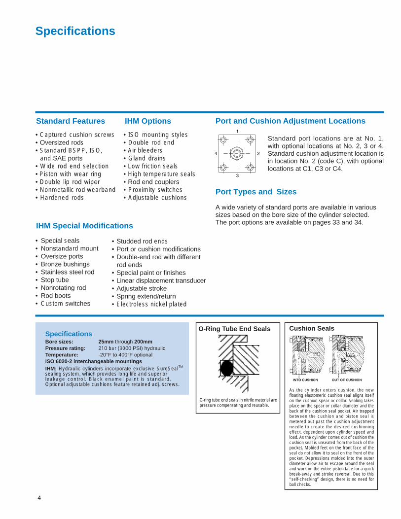
Port and Cushion Adjustment Locations
Standard port locations are at No. 1,with optional locations at No. 2, 3 or 4.Standard cushion adjustment location isin location No. 2 (code C), with optionallocations at C1, C3 or C4.
Port Types and Sizes A wide variety of standard ports are available in various sizes based on the bore size of the cylinder selected.The port options are available on pages 33 and 34.
Specifications
SpecificationsBore sizes: 25mm through 200mmPressure rating: 210 bar (3000 PSI) hydraulicTemperature: -20°F to 400°F optionalISO 6020-2 interchangeable mountingsIHM: Hydraulic cylinders incorporate exclusive SureSealTM
sealing system, which provides long life and superior leakage control. Black enamel paint is standard.Optional adjustable cushions feature retained adj. screws.
O-Ring Tube End Seals
As the cylinder enters cushion, the newfloating elastomeric cushion seal aligns itselfon the cushion spear or collar. Sealing takesplace on the spear or collar diameter and theback of the cushion seal pocket. Air trappedbetween the cushion and piston seal ismetered out past the cushion adjustmentneedle to create the desired cushioningeffect, dependent upon cylinder speed andload. As the cylinder comes out of cushion thecushion seal is unseated from the back of thepocket. Molded feet on the front face of theseal do not allow it to seal on the front of thepocket. Depressions molded into the outerdiameter allow air to escape around the sealand work on the entire piston face for a quickbreak-away and stroke reversal. Due to this“self-checking” design, there is no need forball checks.
Cushion Seals
INTO CUSHION OUT OF CUSHION
O-ring tube end seals in nitrile material arepressure compensating and reusable.
4
• Special seals• Nonstandard mount• Oversize ports• Bronze bushings• Stainless steel rod• Stop tube• Nonrotating rod• Rod boots• Custom switches
IHM Special Modifications
• Studded rod ends• Port or cushion modifications• Double-end rod with different
rod ends• Special paint or finishes• Linear displacement transducer• Adjustable stroke• Spring extend/return• Electroless nickel plated
Standard Features IHM Options

5
How To OrderStandard Cylinders
Eaton has created an easy system forordering Series IHM Cylinders. Thissystem has been developed to improveour service to you. The model codeconsists of sixteen alpha-numeric digitswhich fully describe the most commonstandard options offered on Series IHMcylinders.
To specify your Series IHM cylinder,review the following pages for a fulldescription of each option available andselect the desired code.
This model code system will:
� Simplify the re-order process.Each Hydro-Line Series IHM cylinder isassigned a specific model code.That code is unique to a particularcylinder description. That way, whenyou re-order your Series IHM cylinder,you’re assured of exactly the same topquality cylinder design.
� Improve identification.Every Series IHM cylinder has itscomplete model code clearlymarked on the product, impressionstamped in a metal tag on head/cap.Each modle code completelydescribes a specific cylinder. Thisallows seals and replacementcomponents to be easily identified inthe field.
� Facilitate communications.This fully descriptive model codesystem allows you to work directly withyour local Hydro-Line sales engineer toidentify and service your Hydro-Linecylinder.
NOTESee pages 6 and 7 for a summaryof ISO 6020-2 model code options.
Custom Cylinders
New Cylinders
Although the model code has beenarranged to cover the vast majority ofavailable options, there will beoccasions when you require an optionwhich cannot be coded. Whenspecifying such an option, enter an “X”for the appropriate item in the model code, then describe your requirements. For example, if you have an applicationwhich requires a custom thread on theend of the piston rod, enter an “X” forthe rod end type. Then add a fulldescription at the end of the modelcode, such as “With 80mm total rodprojection and M22 x 1,5 thread 35mmlong.” The cylinder will then be given aunique design number on receipt oforder (as explained below).
If more than one of custom option isrequired, enter an "X" in all the appropriate fields and describe in a suffix. The cylinder will then be given a unique design number onreceipt of your order (as explainedbelow).
Replacement Cylinders
Every Hydro-Line custom cylinder isassigned a unique design number. Thisnumber is contained in the final suffixof the digit model code. When orderinga replacement cylinder, simply give thecomplete model code or the design suffix to your local Hydro-Line SalesRepresentative. Replacement Parts Each design number is stored in a quick retrieval computerized storage system. This gives our field sales
representatives rapid access to assist
you in identifying and specifying genuineHydro-Line replacement parts.

Rod EndStyle
How to Order an IHM CylinderHydro-Line standard cylinders can be completely and accurately identified with a model number that encodes con-struction specifications. To develop the model number for ordering a cylinder, see the following example:
HOW TO ORDER1. Quantity2. Model number3. Special modifications if
required4. Completed Application Data
Sheet(s) (page 9) if required.5. Required ship date
Feature
Specify in millimetresNon-cushionedCushioned both ends (insert locations 1-4)Cushioned head end (insert locations 1-4)Cushioned cap end (insert locations 1-5)Specify in millimetresSpecify in millimetresInclude ONLY for double-rod cylinderSide lugs, MS2Cap fixed clevis, MP1Cap fixed eye, MP3Cap spherical bearing, MP5Head rectangular, ME5No mountAll tie rods extended, MX1Head end tie rods extended, MX3Cap end tie rods extended, MX2Cap rectangular, ME6Intermediate fixed trunnion, MT4Head trunnion, MT1Cap trunnion, MT2ISO 6020/2 interchangeableStyle #2Style #2M (male modified)*Style #4Style #4M (female modified)*Style #7Special*BSP/G (ISO 228/1) - (standard)Metric (DIN 3852 form X)Special Urethane U-cup (standard)VitonSpecialRadial seal with energizer (standard) Low breakaway Teflon radial seal with
wearband (standard)SpecialPosition #1Position #2Position #3Position #4SpecialPosition #1Position #2Position #3Position #4Position #5SpecialInclude ONLY if special modifications arerequired.Air bleeders Rod bootsDrainbacks Indicator switchesSpecial seals Four rod end flatsNon-std. mount Port or cushionOversize ports modificationsBronze bushings Double-end rod withKey plate different rod endsSS rod Special paint/platingStop tube Linear displacement
transducer
–NB_H_C_––DAC
CECSGKLMNPTTUW
IHM2
2M4
4M7MGDXHFXB
TX1234X12345XX
Customer Number (if desired)Hydro-Line Serial Number
Eaton | Hydro-Line
IIHHMMAADD--8800XX110000--NN--3366--22--GG--HH--BB--11--11--XX119944001111223344--11AA1111557799--337755
24
3
1
PortLocation–Head
Mounting Style
Model/Series
Ports
Rod Seals
Piston Seals
PortLocation–Cap
SpecialModifications
Rod Diameter
Cushions
StrokeBore
Double Rod
6
IHMAD-80X100-N-36-2-G-H-B-1-1-X
*Include drawing or description
Port LocationsPort location #5 is on the center of the back face of the cap.
Description Symbol

End MountingsEnd mounted cylinders absorb force on the centerline of the cylinder and are suitable for straight line force trans-fer applications. These mounts allow the thrust or tension forces of the piston rod to be uniformly distributed aboutthe cylinder centerline. If end mounted cylinders are required specify mounts L, N, M, G, or P. See pages 11 thru22 for mounting dimensions. IHM series cylinders also satisfy all of the requirements of DIN 24 554 specifications.
Hydro-Line ISODescription Mount Designation
Tie Rods Extended L, N, M MX1, MX2, MX3Head Rectangular G ME5 (does not meet DIN)Cap Rectangular P ME6
Side MountingSide lugs mounted cylinders do not absorb force along their centerlines. The thrust of the cylinder is aligned par-allel to, but not on, the centerline of the cylinder. For this reason side mounted cylinders produce a turning momentas the cylinder moves the load, this tends to rotate the cylinder about its mounting bolts. For this reason it is impor-tant that the cylinder is firmly secured to the mounting surface and the load is firmly guided to reduce side loadingon the rod gland and piston. An extended key plate may be specified to provide positive cylinder location. ConsultEaton for details. If a side lugs mounted cylinder is required specify mounting style A. See page 9 for mountingdimensions.
Hydro-Line ISODescription Mount Designation
Side Lugs A MS2
End and Intermediate Pivot MountingsTrunnion and clevis mounted cylinders allow the centerline of the cylinder to swing. These cylinders should be usedwhen the actuated load travels through an arc. Trunnion and pivot pins are designed to carry shear loads only.Trunnion and pivot bearings must fit closely for the entire length of the pivot pin. Trunnion bearings should be heldrigidly and be accurately aligned. If pivot mounted cylinders are required specify mounts C, CE, CS, U, W, or TT.See the appropriate pages for mounting dimensions.
Hydro-Line ISODescription Mount Designation
Cap Fixed Clevis C MP1Cap Fixed Eye CE MP3
Cap Spherical Bearing CS MP5Head Trunnion U MT1Cap Trunnion W MT2
Intermediate Fixed Trunnion TT MT4
IHM Series Mounting Application Data
Double Rod CylindersDouble rod cylinders are available in all mountings except C, CE, CS, and W. Use the basic dimensional informa-tion on page 22 combined with dimensions in the other appropriate mounting drawings.
Mounting AccessoriesSee pages 24-31 for mounting accessories.
7
IHM
8
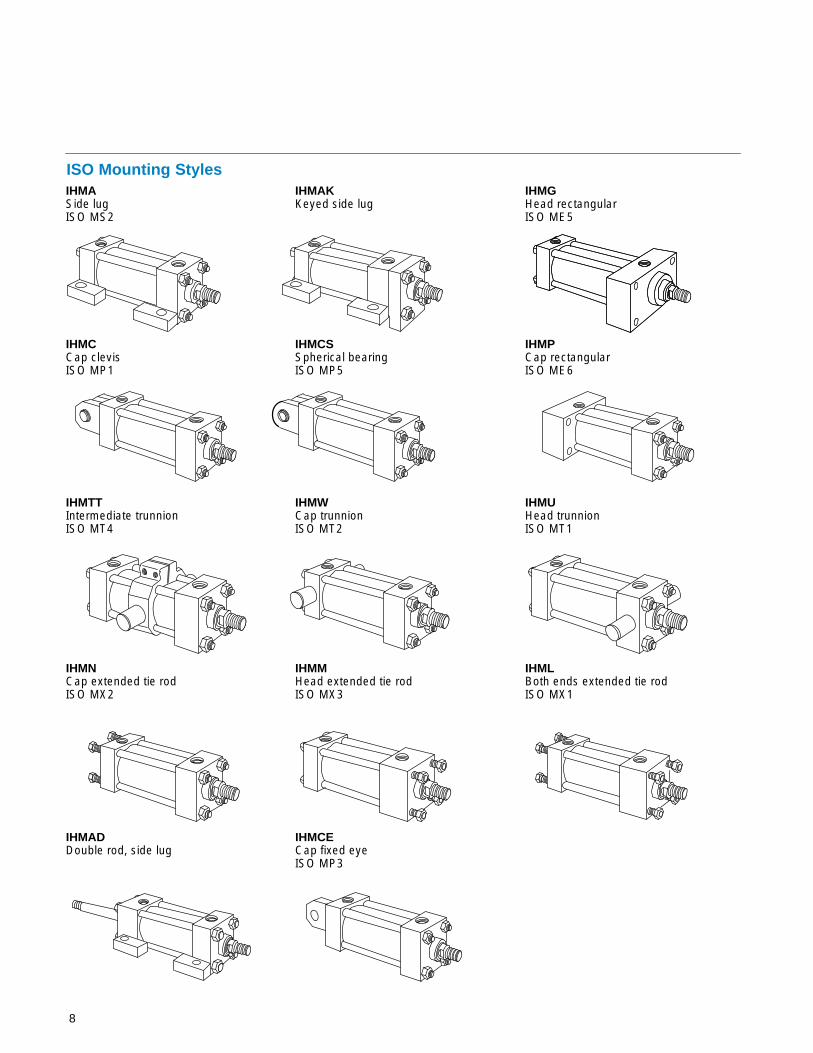
ISO Mounting StylesIHMASide lugISO MS2
IHMAKKeyed side lug
IHMGHead rectangularISO ME5
IHMCCap clevisISO MP1
IHMCSSpherical bearingISO MP5
IHMPCap rectangularISO ME6
IHMTTIntermediate trunnionISO MT4
IHMWCap trunnionISO MT2
IHMUHead trunnionISO MT1
IHMNCap extended tie rodISO MX2
IHMMHead extended tie rodISO MX3
IHMLBoth ends extended tie rodISO MX1
IHMADDouble rod, side lug
IHMCECap fixed eyeISO MP3
9
IHM Series Mounting Styles & Installation Dimensions
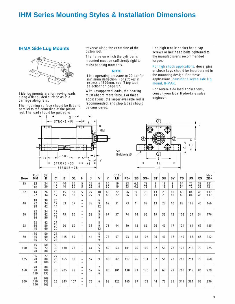
IHMA Side Lug Mounts
Side lug mounts are for moving loadsalong a flat guided surface as in acarriage along rails.
The mounting surface should be flat andparallel to the centerline of the pistonrod. The load should be guided to
traverse along the centerline of thepiston rod.
The frame on which the cylinder ismounted must be sufficiently rigid toresist bending moments.
NOTELimit operating pressure to 70 bar forminimum deflection. For strokes inexcess of 600mm, see “Stop tubeselection” on page 37.
With unsupported loads, the bearingmust absorb more force. For theseapplications, the larger available rod isrecommended, and stop tubes shouldbe considered.
Use high tensile socket head capscrews or hex head bolts tightened tothe manufacturer’s recommendedtorque.
For high shock applications, dowel pinsor shear keys should be incorporated inthe mounting design. For theseapplications, consider a keyed side lugmount, IHMAK.
For severe side load applications,consult your local Hydro-Line salesengineer.
STROKE + PJ
STROKE + SSSTROKE + ZB
XSV
C
MM
BY
3
1
24
SBBolt hole ∅
TS
E
US
STLH
E
H
SUSY SY
J G1
BoreRodMM
(f9)B C E G1 H J V Y
(h10)LH PJ+ SB SS+ ST SU SY TS US XS
MaxZB+
25 1218
2430
1010
4040
5050
55
2525
66
5050
1919
5353
6,66,6
7373
99
1919
88
5454
7272
3333
121121
32 1422
2634
1517
4545
5050
55
2727
109
6060
2222
5656
99
7373
1313
2323
1010
6363
8484
4545
137137
40182228
303442
201714
63 57–––
386912
62 31 73 11 98 13 23 10 83 103 45 166
50222836
344250
172017
75 60–––
38959
67 37 74 14 92 19 33 12 102 127 54 176
63283645
425060
272420
90 60–––
385912
71 44 80 18 86 26 40 17 124 161 65 185
80364556
506072
262323
115 69–––
44599
77 57 93 18 105 26 40 17 149 186 68 212
100455670
607288
303026
130 73–––
44559
82 63 101 26 102 32 51 22 172 216 79 225
125567090
7288108
272626
165 80–––
57 9 86 82 117 26 131 32 51 22 210 254 79 260
1607090110
88108133
26 205 88–––
57766
86 101 130 33 130 38 63 29 260 318 86 279
20090110140
108133163
26 245 107–––
76 6 98 122 165 39 172 44 73 35 311 381 92 336

10
IHMAK Keyed Side LugMounts
Keyed side lug mounts are for movingloads along a flat guided surface as in acarriage along rails.
The mounting surface should be flat andparallel to the centerline of the pistonrod. The load should be guided totraverse along the centerline of thepiston rod.
The frame on which the cylinder ismounted must be sufficiently rigid toresist bending moments.
NOTELimit operating pressure to 100 bar forminimum deflection. For strokes inexcess of 600mm, see “Stop tubeselection” on page 37.
With unsupported loads, the bearingmust absorb more force. For theseapplications, the larger available rod isrecommended, and stop tubes shouldbe considered.
Use high tensile socket head capscrews or hex head bolts tightened tothe manufacturer’s recommendedtorque.
For severe side load applications,consult your local Hydro-Line salesengineer.
STROKE + PJ
STROKE + SSSTROKE + ZB
XSV
C
MMB
Y
3
1
24
SBBolt hole ∅
TSE
US
LH
K
KH
H
E/2
S
ST
G1J
SY SU SY
BoreRodMM
(f9)B C E G1 H J K S V Y
MaxKH
(h10)LH PJ+ SB SS+ ST SU SY TS US XS
MaxZB+
25 1218
2430
1010
4040
5050
55
2525
88
1010
66
5050
2424
1919
5353
6,66,6
7373
99
1919
88
5454
7272
3333
121121
32 1422
2634
1517
4545
5050
55
2727
88
1212
109
6060
2727
2222
5656
99
7373
1313
2323
1010
6363
8484
4545
137137
40182228
303442
201714
63 57–––
38 8 126912
62 36 31 73 11 98 13 23 10 83 103 45 166
50222836
344250
172017
75 60–––
38 14 15959
67 45 37 74 14 92 19 33 12 102 127 54 176
63283645
425060
272420
90 60–––
38 14 195912
71 52 44 80 18 86 26 40 17 124 161 65 185
80364556
506072
262323
115 69–––
44 18 19599
77 67 57 93 18 103 26 40 17 149 186 68 212
100455670
607288
303026
130 73–––
44 22 22559
82 74 63 101 26 102 32 51 22 172 216 79 225
125567090
7288108
272626
165 80–––
57 22 22 9 86 93 82 117 26 131 32 51 22 210 254 79 260
1607090110
88108133
26 205 88–––
57 25 29766
86 114 101 130 33 130 38 63 29 260 318 86 279
20090110140
108133163
26 245 107–––
76 25 35 6 98 135 122 165 39 172 44 73 35 311 381 92 336

11
DHMG Head RectangularMounts (DIN ME5)
These mounts are ideal for straight lineforce transfer applications in which thecylinder is used in tension (pulling).
The mounting surface should be flat,and the rod end cartridge should bepiloted into it.
The frame on which the cylinder ismounted must be sufficiently rigid toresist bending moments.
NOTEFor strokes in excess of 600mm, see“Stop tube selection” on page 37.
The force of the load should beperpendicular to the mounting surface
and parallel to the centerline of thepiston rod. For eccentric loads, thelarger of the two available rods in eachbore size is recommended. Stop tubesshould also be considered.
The head rectangular mounts (DHMGand IHMG) are recommended for heavyduty applications.
Use high tensile socket head capscrews or hex head bolts tightened tothe manufacturer’s recommendedtorque.
STROKE + PJ
STROKE + ZB
VC
MM
B
Y
3
1
24
FBBolt hole ∅F
WF
E
R
TOUO
RD
GF
H
E
J
G1
BoreRodMM
(f9)B C E
MaxF G1 GF H J R V Y FB PJ+
(f8)RD TO
MaxUO WF
MaxZB+
25 1218
2430
1010
4040
1010
5050
2525
55
2525
2727
66
5050
5,55,5
5353
3838
5151
6565
2525
121121
32 1422
2634
1517
4545
1010
5050
2525
55
2727
3333
109
6060
6,66,6
5656
4242
5858
7070
3535
137137
40182228
303442
201714
63 10 57 38–––
38 416912
62 11 73 62 87 110 35 166
50222836
344250
172017
75 16 60 38–––
38 52959
67 14 74 74 105 130 41 176
63283645
425060
272420
90 16 60 38–––
38 655912
71 14 80758288
117 145 48 185
80364556
506072
262323
115 20 69 45–––
44 83599
77 18 938292105
149 180 51 212
100455670
607288
303026
130 22 73 45–––
44 97559
82 18 10192105125
162 200 57 225
125567090
7288108
272626
165 22 80 58–––
57 126 9 86 22 117105125150
208 250 57 260
1607090110
88108133
26 205 25 88 58–––
57 155766
86 26 130125150170
253 300 57 279
20090110140
108133163
26 245 25 107 76–––
76 190 6 98 33 165150170210
300 360 57 336

12
IHMG Head RectangularMounts (ISO ME5)
These mounts are ideal for straight lineforce transfer applications in which thecylinder is used in tension (pulling).
The mounting surface should be flat,and the rod end cartridge should bepiloted into it.
The frame on which the cylinder ismounted must be sufficiently rigid toresist bending moments.
NOTEFor strokes in excess of 600mm, see“Stop tube selection” on page 37.
The force of the load should beperpendicular to the mounting surface
and parallel to the centerline of thepiston rod. For eccentric loads, thelarger of the two available rods in eachbore size is recommended. Stop tubesshould also be considered.
The head rectangular mounts (DHMGand IHMG) are recommended for heavyduty applications.
Use high tensile socket head capscrews or hex head bolts tightened tothe manufacturer’s recommendedtorque.
STROKE + PJ
STROKE + ZB
VC
MM
B
Y
3
1
24
FBBolt hole ∅
E
F
WF
R
RD
G
H
ETOUO
G1
J
BoreRodMM
(f9)B C E
MaxF G G1 H J R V Y FB PJ+
(f8)RD TO
MaxUO WF
MaxZB+
25 1218
2430
1010
4040
1010
4040
5050
55
2525
2727
66
5050
5,55,5
5353
3838
5151
6565
2525
121121
32 1422
2634
1517
4545
1010
4040
5050
55
2727
3333
109
6060
6,66,6
5656
4242
5858
7070
3535
137137
40182228
303442
201714
63 10 47 57–––
38 416912
62 11 73 62 87 110 35 166
50222836
344250
172017
75 16 44 60–––
38 52959
67 14 74 74 105 130 41 176
63283645
425060
272420
90 16 44 60–––
38 655912
71 14 80758288
117 145 48 185
80364556
506072
262323
115 20 49 69–––
44 83599
77 18 938292105
149 180 51 212
100455670
607288
303026
130 22 51 73–––
44 97559
82 18 10192105125
162 200 57 225
125567090
7288108
272626
165 22 58 80–––
57 126 9 86 22 117105125150
208 250 57 260
1607090110
88108133
26 205 25 58 88–––
57 155766
86 26 130125150170
253 300 57 279
20090110140
108133163
26 245 25 76 107–––
76 190 6 98 33 165150170210
300 360 57 336

13
IHMC Clevis Mount (ISO MP1)
These mounts are for applications inwhich the machine member travels in acurved path within one plane.
These mounts can be used both incompression (push) and tension (pull).Care must be exercised to prevent rod buckling in compression applicationswith long strokes. See page 39 forstroke limitations.
NOTEFor strokes in excess of 500mm, see“Stop tube selection” on page 37.
The centerline of the machine memberthat attaches to the swivel pin must beperpendicular to the centerline of thepiston rod and the curved path must bein one plane only. Any misalignment willcause excess side loading on thebearing and piston. This will lead topremature failure. For applications withsmall amounts of misalignment,consider the spherical bearing mount,IHMCS.
H
STROKE + PJ
STROKE + XC
V
C
MM
B
Y
3
1
2 4
E
E CD ∅
L
CBCW CW
LR
MR
Swivel pin included
JG1
BoreRodMM
(f9)B C E G1 H J
MinL V Y
(A16)CB
(f8)CD
MaxCW
MinLR
MaxMR PJ+ XC+
25 1218
2430
1010
4040
5050
55
2525
1313
66
5050
1212
1010
8,58,5
1212
1212
5353
127127
32 1422
2634
1517
4545
5050
55
2727
1919
109
6060
1616
1212
10,510,5
1717
1717
5656
147147
40182228
303442
201714
63 57–––
38 1969
1262 20 14 12,5 17 17 73 172
50222836
344250
172017
75 60–––
38 32959
67 30 20 18 29 29 74 191
63283645
425060
272420
90 60–––
38 3259
1271 30 20 18 29 29 80 200
80364556
506072
262323
115 69–––
44 39599
77 40 28 23,5 34 34 93 229
100455670
607288
303026
130 73–––
44 54559
82 50 36 28,5 50 50 101 257
125567090
7288108
272626
165 80–––
57 57 9 86 60 45 34,5 53 53 117 289
1607090110
88108133
26 205 88–––
57 63766
86 70 56 39,5 59 59 130 308
20090110140
108133163
26 245 107–––
76 82 6 98 80 70 44,5 78 78 165 381
14
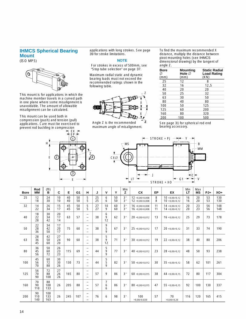
IHMCS Spherical BearingMount (ISO MP5)
This mount is for applications in which themachine member travels in a curved pathin one plane where some misalignment isunavoidable. The amount of allowablemisalignment can be calculated.
This mount can be used both incompression (push) and tension (pull)applications. Care must be exercised toprevent rod buckling in compression
applications with long strokes. See page39 for stroke limitations.
NOTEFor strokes in excess of 500mm, see“Stop tube selection” on page 37.
Maximum radial static and dynamicbearing loads must not exceed therecommended ratings shown in thefollowing table.
Z
Z
X
X
Angle Z is the recommendedmaximum angle of misalignment.
To find the maximum recommended Xdistance, multiply the distance betweenpivot mounting holes (see IHMCSdimensional drawing) by the tangent ofangle Z.Bore Mounting Static Radial∅ Hole ∅ Load Rating(mm) (mm) (KN)
25 12 832 16 12,540 20 2050 25 3263 30 5080 40 80
100 50 125125 60 200160 80 320200 100 500
See page 31 for spherical rod endbearing accessory.
STROKE + PJ
STROKE + XOV
C
MM
B
Y
3
1
2 4
E
E CX∅
MS
LT
EP
Z
H
EX
JG1
BoreRodMM
(f9)B C E G1 H J V Y
MinZ CX EP EX
MinLT
MaxMS PJ+ XO+
25 1218
2430
1010
4040
5050
55
2525
66
5050
3 �3 �
12 +0,00/-0,00812 +0,00/-0,008
88
10 +0,00/-0,1210 +0,00/-0,12
1616
2020
5353
130130
32 1422
2634
1517
4545
5050
55
2727
109
6060
3 �3 �
16 +0,00/-0,00816 +0,00/-0,008
1111
14 +0,00/-0,1214 +0,00/-0,12
2020
2323
5656
148148
40182228
303442
201714
63 57–––
386912
62 3 � 20 +0,00/-0,012 13 16 +0,00/-0,12 25 29 73 178
50222836
344250
172017
75 60–––
38959
67 3 � 25 +0,00/-0,012 17 20 +0,00/-0,12 31 33 74 190
63283645
425060
272420
90 60–––
385912
71 3 � 30 +0,00/-0,012 19 22 +0,00/-0,12 38 40 80 206
80364556
506072
262323
115 69–––
44599
77 3� 40 +0,00/-0,012 23 28 +0,00/-0,12 48 50 93 238
100455670
607288
303026
130 73–––
44559
82 3� 50 +0,00/-0,012 30 35 +0,00/-0,12 58 62 101 261
125567090
7288108
272626
165 80–––
57 9 86 3� 60 +0,00/-0,015 38 44 +0,00/-0,15 72 80 117 304
1607090110
88108133
26 205 88–––
57766
86 3� 80 +0,00/-0,015 47 55 +0,00/-0,15 92 100 130 337
20090110140
108133163
26 245 107–––
76 6 98 3� 100+0,00/-0,020
57 70+0,00/-0,20
116 120 165 415
15
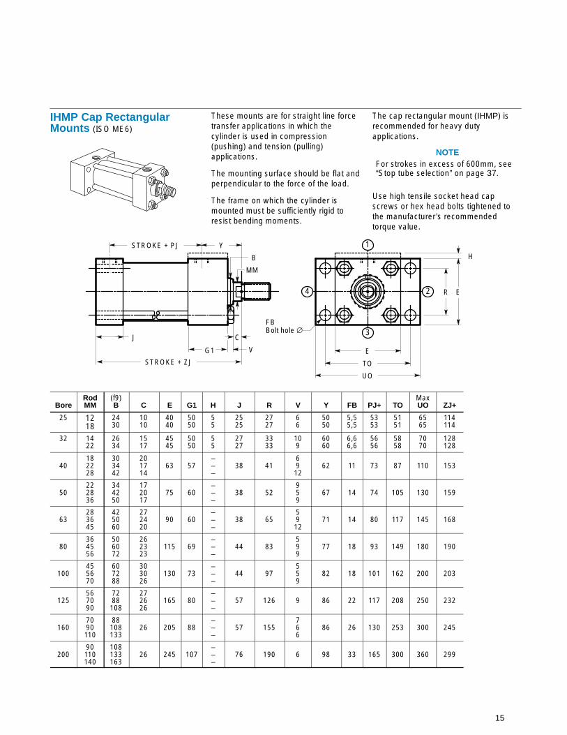
IHMP Cap RectangularMounts (ISO ME6)
These mounts are for straight line forcetransfer applications in which thecylinder is used in compression(pushing) and tension (pulling)applications.
The mounting surface should be flat andperpendicular to the force of the load.
The frame on which the cylinder ismounted must be sufficiently rigid toresist bending moments.
The cap rectangular mount (IHMP) isrecommended for heavy dutyapplications.
NOTEFor strokes in excess of 600mm, see“Stop tube selection” on page 37.
Use high tensile socket head capscrews or hex head bolts tightened tothe manufacturer’s recommendedtorque value.
STROKE + PJ
STROKE + ZJ
V
C
MM
B
Y
3
1
24
FBBolt hole ∅
E
E
R
TO
UO
J
H
G1
BoreRodMM
(f9)B C E G1 H J R V Y FB PJ+ TO
MaxUO ZJ+
25 1218
2430
1010
4040
5050
55
2525
2727
66
5050
5,55,5
5353
5151
6565
114114
32 1422
2634
1517
4545
5050
55
2727
3333
109
6060
6,66,6
5656
5858
7070
128128
40182228
303442
201714
63 57–––
38 416912
62 11 73 87 110 153
50222836
344250
172017
75 60–––
38 52959
67 14 74 105 130 159
63283645
425060
272420
90 60–––
38 655912
71 14 80 117 145 168
80364556
506072
262323
115 69–––
44 83599
77 18 93 149 180 190
100455670
607288
303026
130 73–––
44 97559
82 18 101 162 200 203
125567090
7288108
272626
165 80–––
57 126 9 86 22 117 208 250 232
1607090110
88108133
26 205 88–––
57 155766
86 26 130 253 300 245
20090110140
108133163
26 245 107–––
76 190 6 98 33 165 300 360 299

16
IHMTT Intermediate TrunnionMount (ISO MT4)
The Intermediate Trunnion Mount is forlonger stroke applications in which themachine member travels in a curvedpath in one plane.
On special orders, the trunnion can belocated anywhere along the body.
This mount can be used both incompression (push) and tension (pull)applications.
NOTEFor strokes in excess of 500mm, see“Stop tube selection” on page 37.
It is recommended that rigidly mountedpillow blocks with bearings at least aslong as the trunnion pins be used. Thepillow blocks should be installed asclose to the shoulder of the trunnion aspossible.
STROKE + PJ
V
C
MM
B
Y
3
1
24 E
E
TMSTROKE + ZB
TA
TD
UW
UM
TL TL
R
H
XV
G1J
BoreRodMM
(f9)B C E G1 H J R V Y PJ+ TA TD TL TM UM
MaxUW Min
XV*Std* Max+
MaxZB+
25 1218
2430
1010
4040
5050
55
2525
1,51,5
66
5050
5353
17,517,5
12 –0,016/-0,04312 –0,016/-0,043
1010
4848
6868
6363
8282
7777
7272
121121
32 1422
2634
1517
4545
5050
55
2727
1,51,5
109
6060
5656
20,020,0
16 –0,016/-0,04316 –0,016/-0,043
1212
5555
7979
7575
9696
8989
8282
137137
40182228
303442
201714
63 57–––
38 2,06912
62 73 29,0 20 –0,020/-0,053 16 76 108 92 107 98 88 166
50222836
344250
172017
75 60–––
38 2,0959
67 74 38,5 25 –0,020/-0,053 20 89 129 112 117 104 90 176
63283645
425060
272420
90 60–––
38 2,05912
71 80 42,5 32 –0,025/-0,064 25 100 150 126 132 112 91 185
80364556
506072
262323
115 69–––
44 2,0599
77 93 51,0 40 –0,025/-0,064 32 127 191 160 147 123 99 212
100455670
607288
303026
130 73–––
44 2,0559
82 101 66,0 50 –0,025/-0,064 40 140 220 180 158 133 107 225
125567090
7288
108
272626
165 80–––
57 2,0 9 86 117 84,0 63 –0,030/-0,076 50 178 278 215 180 145 109 260
1607090110
88108133
26 205 88–––
57 2,0766
86 130 106 80 –0,030/-0,076 63 215 341 260 198 154 104 279
20090110140
108133163
26 245 107–––
76 2,0 6 98 165 133 100–0,036/-0,090
80 279 439 355 226 181 130 336
* The standard XV dimension is Stroke/2 + XV (std.) unless otherwise specified.+ Plus stroke
17
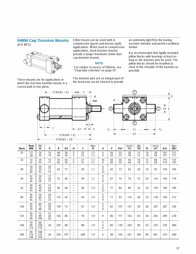
IHMW Cap Trunnion Mounts(ISO MT2)
These mounts are for applications inwhich the machine member travels in acurved path in one plane.
Either mount can be used both incompression (push) and tension (pull)applications. When used in compressionapplications, head trunnion mountsprovide a longer maximum stroke thancap trunnion mounts.
NOTEFor strokes in excess of 500mm, see“Stop tube selection” on page 37.
The trunnion pins are an integral part ofthe head and can be sleeved to provide
an extremely tight fit to the matingmachine member and permit curvilinearmotion.
It is recommended that rigidly mountedpillow blocks with bearings at least aslong as the trunnion pins be used. Thepillow blocks should be installed asclose to the shoulder of the trunnion aspossible.
STROKE + PJ
V
C
MM
B
Y
3
1
24 E
TC
UT
STROKE + ZB
TD
TL TL
R
STROKE + XJ
H
J G1
BoreRodMM
(f9)B C E G1 H J
MaxR V Y PJ+
(h14)TC
(f8)TD TL
(h15)UT XJ+
MaxZB+
25 1218
2430
1010
4040
5050
55
2525
1,11,1
66
5050
5353
3838
1212
1010
5858
101101
121121
32 1422
2634
1517
4545
5050
55
2727
1,11,1
109
6060
5656
4444
1616
1212
6868
115115
137137
40182228
303442
201714
63 57–––
38 1,16912
62 73 63 20 16 95 134 166
50222836
344250
172017
75 60–––
38 1,1959
67 74 76 25 20 116 140 176
63283645
425060
272420
90 60–––
38 1,95912
71 80 89 32 25 139 149 185
80364556
506072
262323
115 69–––
44 1,9599
77 93 114 40 32 178 168 212
100455670
607288
303026
130 73–––
57 1,9559
82 101 127 50 40 207 187 235
125567090
7288108
272626
165 80–––
70 1,9 9 86 117 165 63 50 265 209 270
1607090110
88108133
26 205 88–––
89 1,9766
86 130 203 80 63 329 230 305
20090110140
108133163
26 245 107–––
108 1,9 6 98 165 241 100 80 401 276 360
18
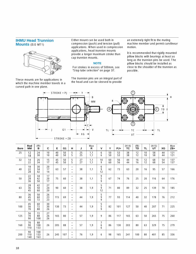
IHMU Head TrunnionMounts (ISO MT1)
These mounts are for applications inwhich the machine member travels in acurved path in one plane.
Either mount can be used both incompression (push) and tension (pull)applications. When used in compressionapplications, head trunnion mountsprovide a longer maximum stroke thancap trunnion mounts.
NOTEFor strokes in excess of 500mm, see“Stop tube selection” on page 37.
The trunnion pins are an integral part ofthe head and can be sleeved to provide
an extremely tight fit to the matingmachine member and permit curvilinearmotion.
It is recommended that rigidly mountedpillow blocks with bearings at least aslong as the trunnion pins be used. Thepillow blocks should be installed asclose to the shoulder of the trunnion aspossible.
STROKE + PJ
V
C
MM
B
Y
3
1
24 E
TC
UT
STROKE + ZB
TD
TL TL
R
XG
H
J G1
BoreRodMM
(f9)B C E G1 H J
MaxR V Y PJ+
(h14)TC
(f8)TD TL
(h15)UT XG
MaxZB+
25 1218
2430
1010
4040
5050
55
2525
1,11,1
66
5050
5353
3838
1212
1010
5858
4444
121121
32 1422
2634
1517
4545
5050
55
2727
1,11,1
109
6060
5656
4444
1616
1212
6868
5454
137137
40182228
303442
201714
63 57–––
38 1,16912
62 73 63 20 16 95 57 166
50222836
344250
172017
75 60–––
38 1,1959
67 74 76 25 20 116 64 176
63283645
425060
272420
90 60–––
38 1,95912
71 80 89 32 25 139 70 185
80364556
506072
262323
115 69–––
44 1,9599
77 93 114 40 32 178 76 212
100455670
607288
303026
130 73–––
44 1,9559
82 101 127 50 40 207 71 225
125567090
7288108
272626
165 80–––
57 1,9 9 86 117 165 63 50 265 75 260
1607090110
88108133
26 205 88–––
57 1,9766
86 130 203 80 63 329 75 279
20090110140
108133163
26 245 107–––
76 1,9 6 98 165 241 100 80 401 85 336
19
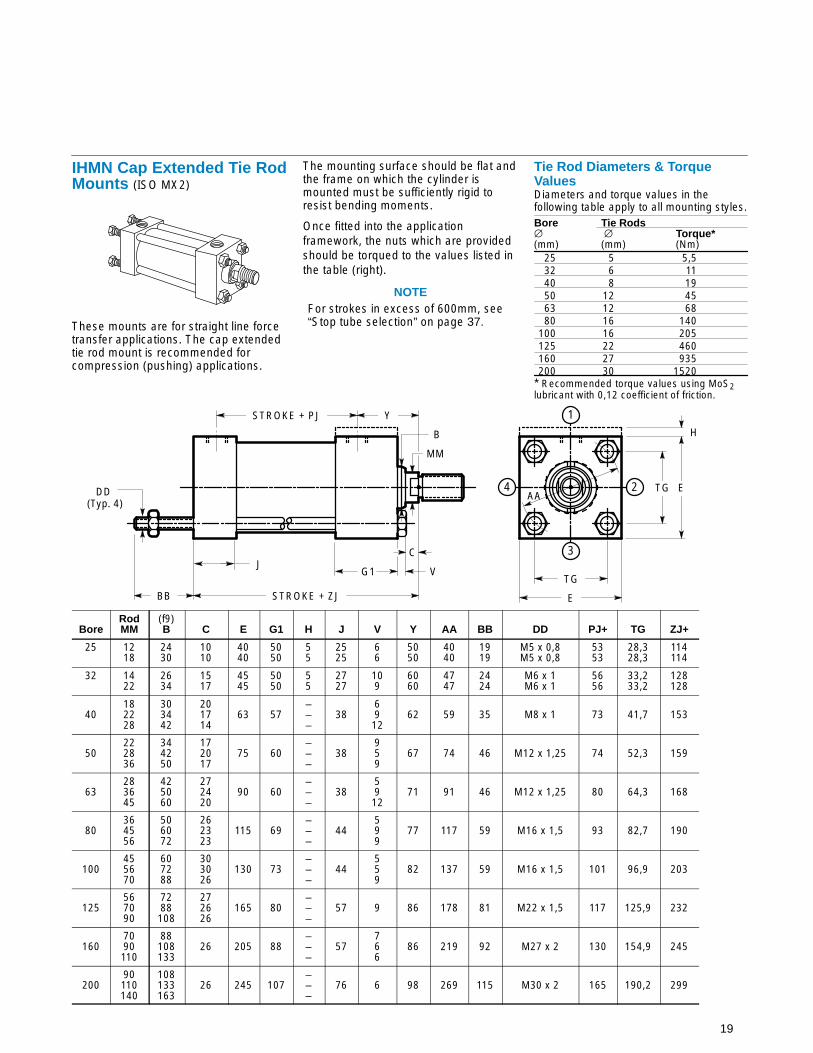
IHMN Cap Extended Tie RodMounts (ISO MX2)
These mounts are for straight line forcetransfer applications. The cap extendedtie rod mount is recommended forcompression (pushing) applications.
The mounting surface should be flat andthe frame on which the cylinder ismounted must be sufficiently rigid toresist bending moments.
Once fitted into the applicationframework, the nuts which are providedshould be torqued to the values listed inthe table (right).
NOTEFor strokes in excess of 600mm, see“Stop tube selection” on page 37.
Tie Rod Diameters & TorqueValuesDiameters and torque values in thefollowing table apply to all mounting styles.Bore Tie Rods∅ ∅ Torque*(mm) (mm) (Nm)
25 5 5,532 6 1140 8 1950 12 4563 12 6880 16 140
100 16 205125 22 460160 27 935200 30 1520
* Recommended torque values using MoS2lubricant with 0,12 coefficient of friction.
STROKE + PJ
V
C
MM
B
Y
3
1
24 E
TG
STROKE + ZJBB E
TGAA
H
DD (Typ. 4)
JG1
BoreRodMM
(f9)B C E G1 H J V Y AA BB DD PJ+ TG ZJ+
25 1218
2430
1010
4040
5050
55
2525
66
5050
4040
1919
M5 x 0,8M5 x 0,8
5353
28,328,3
114114
32 1422
2634
1517
4545
5050
55
2727
109
6060
4747
2424
M6 x 1M6 x 1
5656
33,233,2
128128
40182228
303442
201714
63 57–––
386912
62 59 35 M8 x 1 73 41,7 153
50222836
344250
172017
75 60–––
38959
67 74 46 M12 x 1,25 74 52,3 159
63283645
425060
272420
90 60–––
385912
71 91 46 M12 x 1,25 80 64,3 168
80364556
506072
262323
115 69–––
44599
77 117 59 M16 x 1,5 93 82,7 190
100455670
607288
303026
130 73–––
44559
82 137 59 M16 x 1,5 101 96,9 203
125567090
7288108
272626
165 80–––
57 9 86 178 81 M22 x 1,5 117 125,9 232
1607090110
88108133
26 205 88–––
57766
86 219 92 M27 x 2 130 154,9 245
20090110140
108133163
26 245 107–––
76 6 98 269 115 M30 x 2 165 190,2 299
20
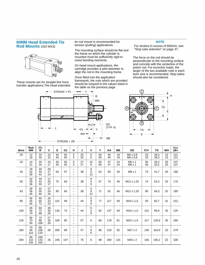
IHMM Head Extended TieRod Mounts (ISO MX3)
These mounts are for straight line forcetransfer applications.The head extended
tie rod mount is recommended fortension (pulling) applications.
The mounting surface should be flat andthe frame on which the cylinder ismounted must be sufficiently rigid toresist bending moments.
On head mount applications, thecartridge provides a pilot diameter toalign the rod in the mounting frame.
Once fitted into the applicationframework, the nuts which are providedshould be torqued to the values listed inthe table on the previous page.
NOTEFor strokes in excess of 600mm, see“Stop tube selection” on page 37.
The force on the rod should beperpendicular to the mounting surfaceand coincide with the centerline of thepiston rod. For eccentric loads, thelarger of the two available rods in eachbore size is recommended. Stop tubesshould also be considered.
H
STROKE + PJ
V
C
MM
B
Y
3
1
24E
TG
STROKE + ZB
E
TGAA
BB
DD(TYP. 4)
WH
J G1
BoreRodMM
(f9)B C E G1 H J V Y AA BB DD PJ+ TG WH
MaxZB+
25 1218
2430
1010
4040
5050
55
2525
66
5050
4040
1919
M5 x 0,8M5 x 0,8
5353
28,328,3
1515
121121
32 1422
2634
1517
4545
5050
55
2727
109
6060
4747
2424
M6 x 1M6 x 1
5656
33,233,2
2525
137137
40182228
303442
201714
63 57–––
386912
62 59 35 M8 x 1 73 41,7 25 166
50222836
344250
172017
75 60–––
38959
67 74 46 M12 x 1,25 74 52,3 25 176
63283645
425060
272420
90 60–––
385912
71 91 46 M12 x 1,25 80 64,3 32 185
80364556
506072
262323
115 69–––
44599
77 117 59 M16 x 1,5 93 82,7 31 212
100455670
607288
303026
130 73–––
44559
82 137 59 M16 x 1,5 101 96,9 35 225
125567090
7288108
272626
165 80–––
57 9 86 178 81 M22 x 1,5 117 125,9 35 260
1607090110
88108133
26 205 88–––
57766
86 219 92 M27 x 2 130 154,9 32 279
20090110140
108133163
26 245 107–––
76 6 98 269 115 M30 x 2 165 190,2 32 336

21
IHML Both Ends ExtendedTie Rod Mounts (ISO MX1)
These mounts are for straight line forcetransfer applications. Both ends
extended tie rod mounts are suited fortension and compression applications orapplications where additional hardwareis to be attached to cylinders.
The mounting surface should be flat andthe frame on which the cylinder ismounted must be sufficiently rigid toresist bending moments.
Once fitted into the applicationframework, the nuts which are providedshould be torqued to the values listed inthe table on page 19.
NOTEFor strokes in excess of 600mm, see“Stop tube selection” on page 37.
The force on the rod should beperpendicular to the mounting surfaceand coincide with the centerline of thepiston rod. For eccentric loads, thelarger of the two available rods in eachbore size is recommended. Stop tubesshould also be considered.
H
STROKE + PJ
V
C
MM
B
Y
3
1
24E
TG
STROKE + ZJ
E
TG
AA
BB
DD(TYP. 8)
BBWH
JG1
BoreRodMM
(f9)B C E G1 H J V Y AA BB DD PJ+ TG WH ZJ+
25 1218
2430
1010
4040
5050
55
2525
66
5050
4040
1919
M5 x 0,8M5 x 0,8
5353
28,328,3
1515
114114
32 1422
2634
1517
4545
5050
55
2727
109
6060
4747
2424
M6 x 1M6 x 1
5656
33,233,2
2525
128128
40182228
303442
201714
63 57–––
386912
62 59 35 M8 x 1 73 41,7 25 153
50222836
344250
172017
75 60–––
38959
67 74 46 M12 x 1,25 74 52,3 25 159
63283645
425060
272420
90 60–––
385912
71 91 46 M12 x 1,25 80 64,3 32 168
80364556
506072
262323
115 69–––
44599
77 117 59 M16 x 1,5 93 82,7 31 190
100455670
607288
303026
130 73–––
44559
82 137 59 M16 x 1,5 101 96,9 35 203
125567090
7288108
272626
165 80–––
57 9 86 178 81 M22 x 1,5 117 125,9 35 232
1607090110
88108133
26 205 88–––
57766
86 219 92 M27 x 2 130 154,9 32 245
20090110140
108133163
26 245 107–––
76 6 98 269 115 M30 x 2 165 190,2 32 299

22
IHMAD Double Rod End, SideLug Mounts (ISO MX1)
Double rod cylinders are specified whenequal displacement is desired on bothsides of the piston, or when theapplication is such that another functioncan be performed simultaneously with asecond rod.
The single rod mount application data isalso applicable to double rod cylinders.
NOTELimit operating pressure to 100 bar forminimum deflection.
STROKE + PJ1
STROKE + SS1
TWICE STROKE + ZM
XS
V
C
MM
B
Y
3
1
24
TS
E
US
STLH
E
PISTON
H
SB BOLTHOLE ∅
STROKE + XS
G1 G1
SUSY SY
BoreRodMM
(f9)B C E G1 H V Y
(h10)LH PJ1+ SB SS1+ ST SU SY TS US XS ZM++
25 1218
2430
1010
4040
5050
55
66
5050
1919
5151
6,66,6
8585
99
1919
88
5454
7272
3333
151151
32 1422
2634
1517
4545
5050
55
109
6060
2222
5656
99
8686
1313
2323
1010
6363
8484
4545
176176
40182228
303442
201714
63 57–––
6912
62 31 69 11 103 13 23 10 83 103 45 193
50222836
344250
172017
75 60–––
959
67 37 72 14 98 19 33 12 102 127 54 206
63283645
425060
272420
90 60–––
5912
71 44 81 18 93 26 40 17 124 161 65 223
80364556
506072
262323
115 69–––
599
77 57 92 18 110 26 40 17 149 186 68 246
100455670
607288
303026
130 73–––
559
82 63 103 26 109 32 51 22 172 216 79 268
125567090
7288108
272626
165 80–––
9 86 82 114 26 128 32 51 22 210 254 79 286
1607090110
88108133
26 205 88–––
766
86 101 137 33 137 38 63 29 260 318 86 309
20090110140
108133163
26 245 107–––
6 98 122 160 39 172 44 73 35 311 381 92 356
+ Plus Stroke++ Plus 2x Stroke
23
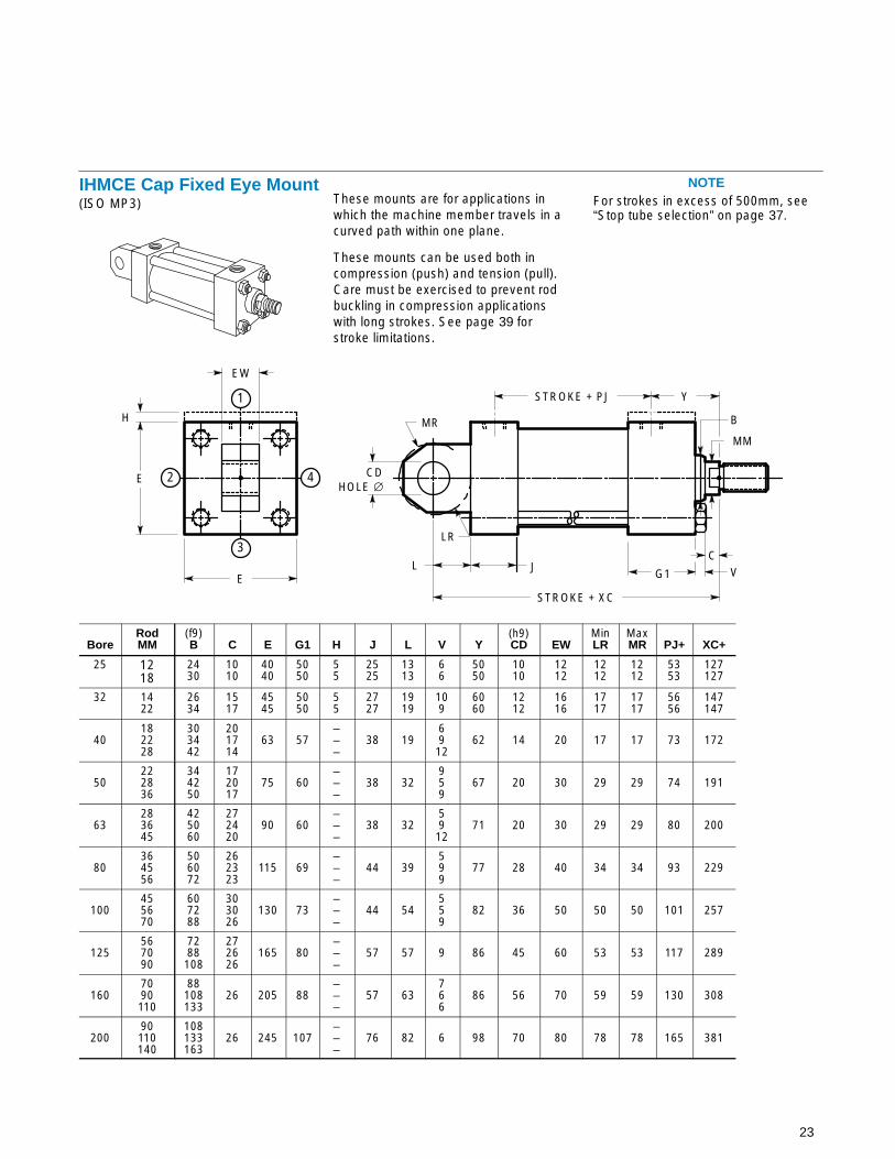
IHMCE Cap Fixed Eye Mount(ISO MP3)
These mounts are for applications inwhich the machine member travels in acurved path within one plane.
These mounts can be used both incompression (push) and tension (pull).Care must be exercised to prevent rod buckling in compression applicationswith long strokes. See page 39 forstroke limitations.
NOTEFor strokes in excess of 500mm, see“Stop tube selection” on page 37.
CDHOLE ∅
LR
MRH
STROKE + PJ
STROKE + XC
VC
MM
B
Y
3
1
2 4
E
E
L
EW
JG1
BoreRodMM
(f9)B C E G1 H J L V Y
(h9)CD EW
MinLR
MaxMR PJ+ XC+
25 1218
2430
1010
4040
5050
55
2525
1313
66
5050
1010
1212
1212
1212
5353
127127
32 1422
2634
1517
4545
5050
55
2727
1919
109
6060
1212
1616
1717
1717
5656
147147
40182228
303442
201714
63 57–––
38 1969
1262 14 20 17 17 73 172
50222836
344250
172017
75 60–––
38 32959
67 20 30 29 29 74 191
63283645
425060
272420
90 60–––
38 3259
1271 20 30 29 29 80 200
80364556
506072
262323
115 69–––
44 39599
77 28 40 34 34 93 229
100455670
607288
303026
130 73–––
44 54559
82 36 50 50 50 101 257
125567090
7288108
272626
165 80–––
57 57 9 86 45 60 53 53 117 289
1607090110
88108133
26 205 88–––
57 63766
86 56 70 59 59 130 308
20090110140
108133163
26 245 107–––
76 82 6 98 70 80 78 78 165 381

24
Accessories
All rod accessories must be torquedagainst the rod shoulder.
Mounting brackets, rod clevises, and rodeyes for all IHM cylinders are availablefrom Eaton. These accessories aredetailed below showing part numbersand all pertinent dimensional data.When ordering, please specify the partname and part number.
Plain Swivel Pin (Includes two retaining rings)
ET
EK∅
EL
Part Min. Max. Maximum Load WeightNumber EK EL ET (kN) (lbs) (kg)
CH-9025-3 10 –0,013/–0,035 29 37,6 8 1800 0,023CH-9032-3 12 –0,016/–0,043 37 45,6 12,5 2800 0,040CH-9040-3 14 –0,016/–0,043 45 53,4 20 4500 0,061CH-9050-3 20 –0,020/–0,053 66 75,2 50 11250 0,182CH-9080-3 28 –0,020/–0,053 87 96,9 80 18000 0,407CH-90100-3 36 –0,025/–0,064 107 120,5 125 28100 0,930CH-90125-3 45 –0,025/–0,064 129 144,0 200 45000 1,635CH-90160-3 56 –0,030/–0,076 149 164,6 320 72000 3,100CH-90200-3 70 –0,030/–0,076 169 187,4 500 112400 5,390
25
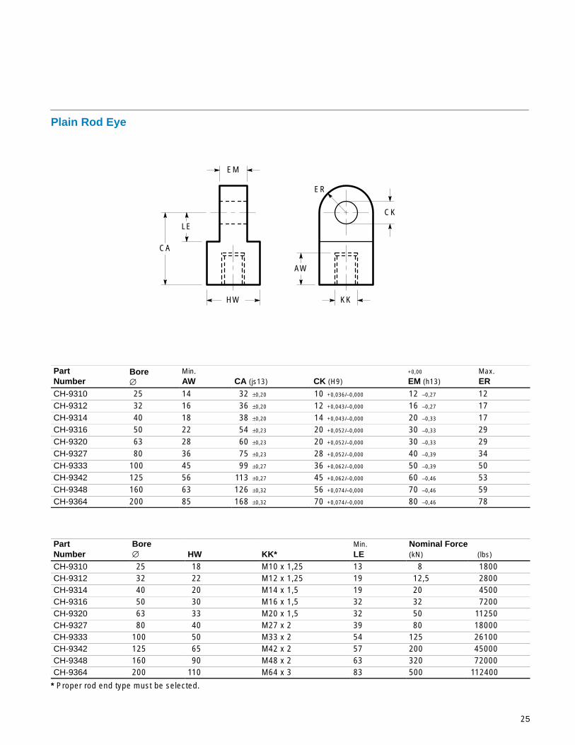
Plain Rod Eye
ER
LE
CA
EM
HW
AW
KK
CK
PartNumber
Bore∅
Min.AW CA (js13) CK (H9)
+0,00
EM (h13)Max.ER
CH-9310 25 14 32 ±0,20 10 +0,036/–0,000 12 –0,27 12CH-9312 32 16 36 ±0,20 12 +0,043/–0,000 16 –0,27 17CH-9314 40 18 38 ±0,20 14 +0,043/–0,000 20 –0,33 17CH-9316 50 22 54 ±0,23 20 +0,052/–0,000 30 –0,33 29CH-9320 63 28 60 ±0,23 20 +0,052/–0,000 30 –0,33 29CH-9327 80 36 75 ±0,23 28 +0,052/–0,000 40 –0,39 34CH-9333 100 45 99 ±0,27 36 +0,062/–0,000 50 –0,39 50CH-9342 125 56 113 ±0,27 45 +0,062/–0,000 60 –0,46 53CH-9348 160 63 126 ±0,32 56 +0,074/–0,000 70 –0,46 59CH-9364 200 85 168 ±0,32 70 +0,074/–0,000 80 –0,46 78
PartNumber
Bore∅ HW KK*
Min.LE
Nominal Force(kN) (lbs)
CH-9310 25 18 M10 x 1,25 13 8 1800CH-9312 32 22 M12 x 1,25 19 12,5 2800CH-9314 40 20 M14 x 1,5 19 20 4500CH-9316 50 30 M16 x 1,5 32 32 7200CH-9320 63 33 M20 x 1,5 32 50 11250CH-9327 80 40 M27 x 2 39 80 18000CH-9333 100 50 M33 x 2 54 125 26100CH-9342 125 65 M42 x 2 57 200 45000CH-9348 160 90 M48 x 2 63 320 72000CH-9364 200 110 M64 x 3 83 500 112400
* Proper rod end type must be selected.

26
Accessories
CP
CS
TA
GL
UK
UJ RE
JPJO
LO
FO
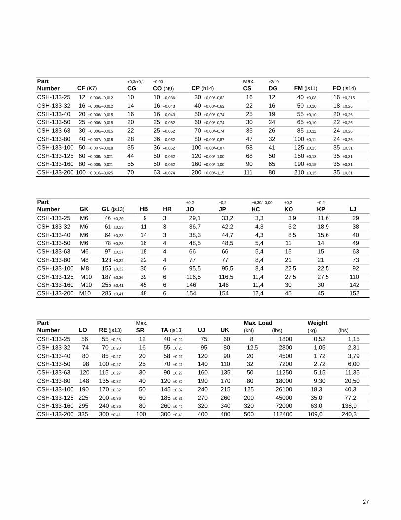
Spherical Bearing Clevis Bracket (per DIN 24556 / ISO 8133)
SR
FM
KC KO KP
CO
GK
HR
DG
HB∅
CF∅
LJ
CG
27
PartNumber CF (K7)
+0,3/+0,1
CG+0,00
CO (N9) CP (h14)Max.CS
+2/–0
DG FM (js11) FO (js14)
CSH-133-25 12 +0,006/–0,012 10 10 –0,036 30 +0,00/–0,62 16 12 40 ±0,08 16 ±0,215
CSH-133-32 16 +0,006/–0,012 14 16 –0,043 40 +0,00/–0,62 22 16 50 ±0,10 18 ±0,26
CSH-133-40 20 +0,006/–0,015 16 16 –0,043 50 +0,00/–0,74 25 19 55 ±0,10 20 ±0,26
CSH-133-50 25 +0,006/–0,015 20 25 –0,052 60 +0,00/–0,74 30 24 65 ±0,10 22 ±0,26
CSH-133-63 30 +0,006/–0,015 22 25 –0,052 70 +0,00/–0,74 35 26 85 ±0,11 24 ±0,26
CSH-133-80 40 +0,007/–0,018 28 36 –0,062 80 +0,00/–0,87 47 32 100 ±0,11 24 ±0,26
CSH-133-100 50 +0,007/–0,018 35 36 –0,062 100 +0,00/–0,87 58 41 125 ±0,13 35 ±0,31
CSH-133-125 60 +0,009/–0,021 44 50 –0,062 120 +0,00/–1,00 68 50 150 ±0,13 35 ±0,31
CSH-133-160 80 +0,009/–0,021 55 50 –0,062 160 +0,00/–1,00 90 65 190 ±0,15 35 ±0,31
CSH-133-200 100 +0,010/–0,025 70 63 –0,074 200 +0,00/–1,15 111 80 210 ±0,15 35 ±0,31
PartNumber GK GL (js13) HB HR
±0,2
JO±0,2
JP+0,30/–0,00
KC±0,2
KO±0,2
KP LJ
CSH-133-25 M6 46 ±0,20 9 3 29,1 33,2 3,3 3,9 11,6 29CSH-133-32 M6 61 ±0,23 11 3 36,7 42,2 4,3 5,2 18,9 38CSH-133-40 M6 64 ±0,23 14 3 38,3 44,7 4,3 8,5 15,6 40CSH-133-50 M6 78 ±0,23 16 4 48,5 48,5 5,4 11 14 49CSH-133-63 M6 97 ±0,27 18 4 66 66 5,4 15 15 63CSH-133-80 M8 123 ±0,32 22 4 77 77 8,4 21 21 73CSH-133-100 M8 155 ±0,32 30 6 95,5 95,5 8,4 22,5 22,5 92CSH-133-125 M10 187 ±0,36 39 6 116,5 116,5 11,4 27,5 27,5 110CSH-133-160 M10 255 ±0,41 45 6 146 146 11,4 30 30 142CSH-133-200 M10 285 ±0,41 48 6 154 154 12,4 45 45 152
PartNumber LO RE (js13)
Max.SR TA (js13) UJ UK
Max. Load(kN) (lbs)
Weight(kg) (lbs)
CSH-133-25 56 55 ±0,23 12 40 ±0,20 75 60 8 1800 0,52 1,15CSH-133-32 74 70 ±0,23 16 55 ±0,23 95 80 12,5 2800 1,05 2,31CSH-133-40 80 85 ±0,27 20 58 ±0,23 120 90 20 4500 1,72 3,79CSH-133-50 98 100 ±0,27 25 70 ±0,23 140 110 32 7200 2,72 6,00CSH-133-63 120 115 ±0,27 30 90 ±0,27 160 135 50 11250 5,15 11,35CSH-133-80 148 135 ±0,32 40 120 ±0,32 190 170 80 18000 9,30 20,50CSH-133-100 190 170 ±0,32 50 145 ±0,32 240 215 125 26100 18,3 40,3CSH-133-125 225 200 ±0,36 60 185 ±0,36 270 260 200 45000 35,0 77,2CSH-133-160 295 240 ±0,36 80 260 ±0,41 320 340 320 72000 63,0 138,9CSH-133-200 335 300 ±0,41 100 300 ±0,41 400 400 500 112400 109,0 240,3

28
Accessories
Swivel Pin for Spherical Bearingwith Retaining Rings
ET
JK∅
ES
PartNumber JK
Max.ET
Min.ES
Max. Load(kN) (lbs)
Weight(kg)
CSH-90-25 12 +0,000/–0,011 39,6 31 8 1800 0,035CSH-90-32 16 +0,000/–0,011 49,6 41 12,5 2800 0,075CSH-90-40 20 +0,000/–0,013 60,2 51 20 4500 0,145CSH-90-50 25 +0,000/–0,013 70,2 61 32 7200 0,260CSH-90-63 30 +0,000/–0,013 80,8 71 50 11250 0,380CSH-90-80 40 +0,000/–0,016 94,5 81 80 18000 0,895CSH-90-100 50 +0,000/–0,016 116,5 101 125 26100 1,630CSH-90-125 60 +0,000/–0,019 136,6 121 200 45000 2,950CSH-90-160 80 +0,000/–0,019 179,2 161 320 72000 6,730CSH-90-200 100 +0,000/–0,022 220,4 201 500 112400 13,500
Swivel Pin for SphericalBearing with Locking Plate KL
DK∅
ZV
SL
2 x JL
HL
DC
2 x ZX
2 x 45°
PartNumber
+0,00
DK (h6) DC+0,2/–0,0
HL JL KL SL ZV ZXMax. Load(kN) (lbs)
Weight(kg)
CSHB-90-25 12 –0,011 4 3,3 4,5 8 40 10 1 8 1800 0,035
CSHB-90-32 16 –0,011 4 3,3 5,5 8 50 13 1 12,5 2800 0,075
CSHB-90-40 20 –0,013 5 4,5 5,5 10 62 17 1,5 20 4500 0,150
CSHB-90-50 25 –0,013 5 4,5 5,5 10 72 22 1,5 32 7200 0,270
CSHB-90-63 30 –0,013 6 5,5 7,5 13 85 24 2 50 11250 0,410
CSHB-90-80 40 –0,016 7 6,5 9,5 16 100 32 2 80 18000 0,950
CSHB-90-100 50 –0,019 8 9,0 10,0 19 122 41 2 125 26100 1,710
CSHB-90-125 60 –0,019 9 9,0 11,0 20 145 50 2 200 45000 3,130
CSHB-90-160 80 –0,019 11 11,0 15,0 26 190 70 3 320 72000 7,140
CSHB-90-200 100 –0,021 14 13,0 15,0 30 235 90 3 500 112400 14,400

29
ÉÉ
ÉÉ
Locking Plate for Swivel Pin
SK
YL
DBBU
XT
XT/2 XT/2
CU
DK (Swivel pin ∅)
PartNumber DK BU DB SK YL
±0,2
XTRef.CU
(2 included)Screw
Weight(kg)
7959–012 12 15 6,4 3 27 16 9,5 M6 x 12 0,015
7959–016 16 15 6,4 3 40 25 11,5 M6 x 12 0,020
7959–020 20 18 6,4 4 40 25 14,5 M6 x 15 0,032
7959–025 25 18 6,4 4 40 25 16,5 M6 x 15 0,032
7959–030 30 20 6,4 5 45 30 19,0 M6 x 15 0,050
7959–040 40 20 8,4 6 62 42 23,0 M8 x 20 0,078
7959–050 50 25 8,4 8 65 45 29,5 M8 x 20 0,090
7959–060 60 25 10,5 8 80 55 33,5 M10 x 25 0,170
7959–080 80 30 10,5 10 90 60 44,0 M10 x 25 0,250
7959–100 100 40 10,5 12 120 90 56,0 M10 x 25 0,490

Bore Diameter (mm)253240506380100125160200
Part No.CH-134-10CH-134-12CH-134-14CH-134-16CH-134-20CH-134-27CH-134-33CH-134-42CH-134-48CH-134-64
A min
14161822283645566385
CD10121420202836455670
CB max
12162030304050607080
CE32363854607599113126168
CW79111616
21,526,531,536,541,5
ERmax
12171729293450535978
KKM10 x 1,25M12 x 1,25M14 x 1,5M16 x 1,5M20 x 1,5M27 x 2M33 x 2M42 x 2M48 x 2M64 x 3
L min
13191932323954576383
30
IHMAccessories
All dimensions in millimetres unless otherwise stated.Plain Rod Clevis
Eye Bracket
MRmax
12171729293450535978
Fmax
10101016162025304050
FL2329294848597987103132
CD10121420202836455670
CB12162030304050607080
BD5,56,69
13,513,517,517,5243033
BA28,333,241,752,364,382,796,9125,9154,9190,2
AA4047597491117137178219269
All dimensions in millimetres unless otherwise stated.
Part No.CH-8925CH-8932CH-8940CH-8950CH-8963CH-8980CH-89100CH-89125CH-89160CH-89200
Part No.CH-9025-3CH-9032-3CH-9040-3CH-9050-3CH-9080-3CH-90100-3CH-90125-3CH-90160-3CH-90200-3
CD 101214202836455670
CLmin
2937456687107129149169
Plain Pivot Pin All dimensions in millimetres unless otherwise stated.
Selecting AccessoriesRod end accessories are selected by the corresponding rod end threads. Cap end accessories are selected bycylinder bore size. Reference the following tables.
Thread KKM10 x 1,25M12 x 1,25M14 x 1,5M16 x 1,5M20 x 1,5M27 x 2M33 x 2M42 x 2M48 x 2M64 x 3
Plain Rod ClevisCH-134-10CH-134-12CH-134-14CH-134-16CH-134-20CH-134-27CH-134-33CH-134-42CH-134-48CH-134-64
Eye BracketCH-8925CH-8932CH-8940CH-8950CH-8963CH-8980CH-89100CH-89125CH-89160CH-89200
Plain Pivot PinCH-9025-3CH-9032-3CH-9040-3CH-9050-3CH-9050-3CH-9080-3CH-90100-3CH-90125-3CH-90160-3CH-90200-3
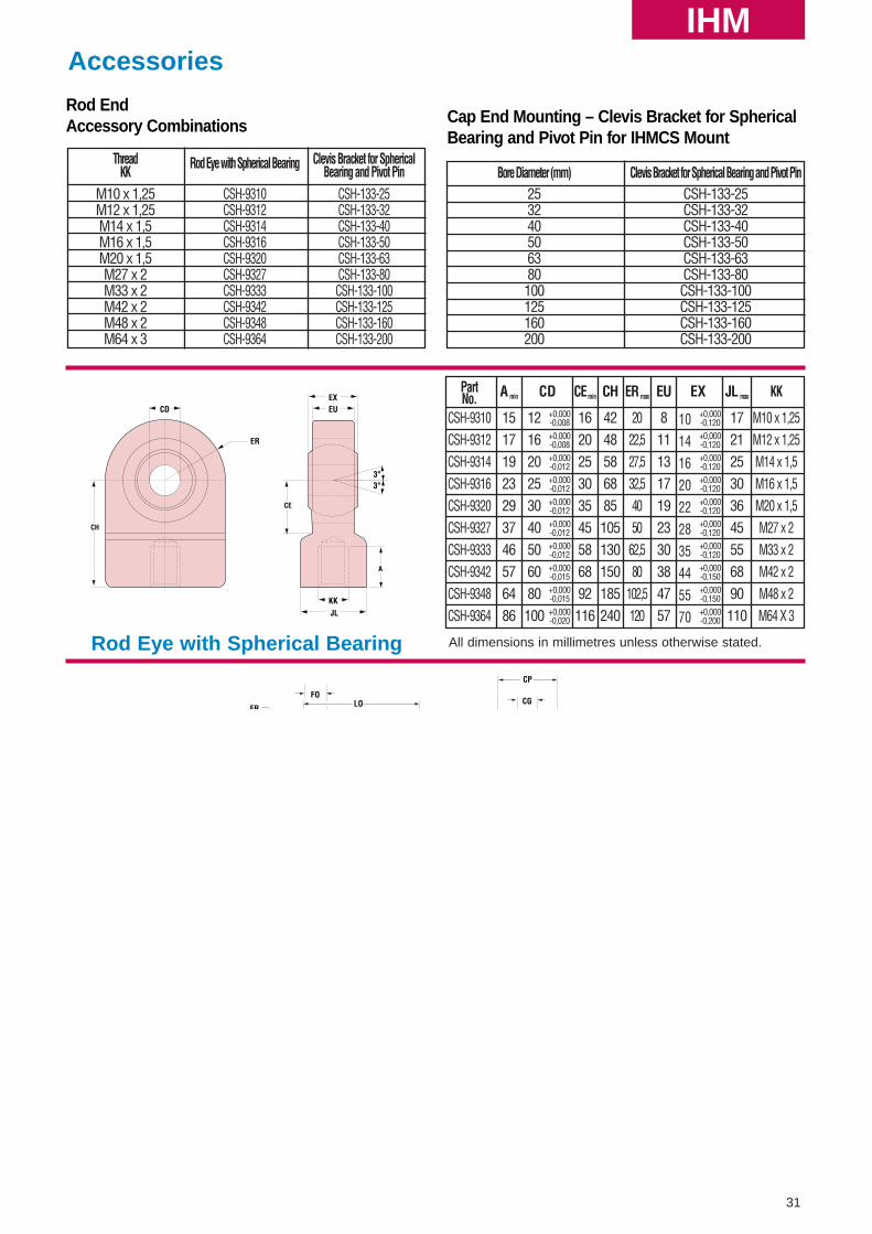
Rod End Accessory Combinations
Cap End Mounting – Eye Bracket for IHMC Mount
Eye BracketCH-8925CH-8932CH-8940CH-8950CH-8963CH-8980CH-89100CH-89125CH-89160CH-89200
CW
CB
A
L
CE
CD
ER
KK
CW
CB
BA
FL
BD
MR
CDAAAA
F
CD
CL
ThreadKK
M10 x 1,25M12 x 1,25M14 x 1,5M16 x 1,5M20 x 1,5M27 x 2M33 x 2M42 x 2M48 x 2M64 x 3
PartNo.
CSH-133-25CSH-133-32CSH-133-40CSH-133-50CSH-133-63CSH-133-80CSH-133-100CSH-133-125CSH-133-160CSH-133-200
31
IHMAccessories
Rod Eye with Spherical Bearing
PartNo.
CSH-9310CSH-9312CSH-9314CSH-9316CSH-9320CSH-9327CSH-9333CSH-9342CSH-9348CSH-9364
A min
15171923293746576486
C
121620253040506080100
D+0,000-0,008+0,000-0,008+0,000-0,012+0,000-0,012+0,000-0,012+0,000-0,012+0,000-0,012+0,000-0,015+0,000-0,015+0,000-0,020
CEmin
162025303545586892116
CH
4248586885105130150185240
ER max
2022,527,532,54050
62,580
102,5120
EU
8111317192330384757
E
10141620222835445570
X+0,000-0,120+0,000-0,120+0,000-0,120+0,000-0,120+0,000-0,120+0,000-0,120+0,000-0,120+0,000-0,150+0,000-0,150+0,000-0,200
JL max
172125303645556890110
KK
M10 x 1,25M12 x 1,25M14 x 1,5M16 x 1,5M20 x 1,5M27 x 2M33 x 2M42 x 2M48 x 2M64 X 3
All dimensions in millimetres unless otherwise stated.
Clevis Bracket for Spherical Bearing and Pivot Pin
All dimensions in millimetres unless otherwise stated.
C
10161625253636505063
O+0,000-0,058+0,000-0,070+0,000-0,070+0,000-0,084+0,000-0,084+0,000-0,100+0,000-0,100+0,000-0,100+0,000-0,100+0,000-0,120
CP
304050607080100120160200
10141620222835445570
121620253040506080100
+0,019+0,001+0,019+0,001+0,023+0,002+0,023+0,002+0,023+0,002+0,027+0,002+0,027+0,002+0,032+0,002+0,032+0,002+0,038+0,003
FM
4050556585100125150190210
FO
16182022242435353535
GL
4661647897123155187255285
HB
9111416182230394548
LG
28373948627290108140150
LJ
29384049637392110142152
LO
56748098120148190225295335
KC+0,3-0,0
3,34,34,35,45,48,48,411,411,412,4
ERmax
121620253040506080100
RE
557085100115135170200240300
TA
4055587090120145185260300
UJ
7595120140160190240270320400
UK
608090110135170215260340400
Clevis Bracket for SphericalBearing and Pivot Pin
CSH-133-25CSH-133-32CSH-133-40CSH-133-50CSH-133-63CSH-133-80CSH-133-100CSH-133-125CSH-133-160CSH-133-200
Rod End Accessory Combinations Cap End Mounting – Clevis Bracket for Spherical
Bearing and Pivot Pin for IHMCS Mount
Bore Diameter (mm)253240506380100125160200
Clevis Bracket for Spherical Bearing and Pivot PinCSH-133-25CSH-133-32CSH-133-40CSH-133-50CSH-133-63CSH-133-80CSH-133-100CSH-133-125CSH-133-160CSH-133-200
Rod Eye with Spherical Bearing
CSH-9310CSH-9312CSH-9314CSH-9316CSH-9320CSH-9327CSH-9333CSH-9342CSH-9348CSH-9364
ER
CH
CDEXEU
JLKK
CE
A
3°3°
LOER
GL
KC
FMLG
TA
HBDia.
RE
CP
FO CG
UK
UJ
CO
LJ
CD
CG+0,3-0,1
CDPin Dia.
32
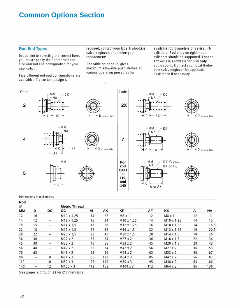
Common Options Section
Rod End Types
In addition to selecting the correct bore,you must specify the appropriate rodsize and rod end configuration for yourapplication.
Five different rod end configurations areavailable. If a custom design is
required, contact your local Hydro-Linesales engineer, and define yourrequirements.
The table on page 39 givesmaximum allowable push strokes atvarious operating pressures for
available rod diameters of Series IHMcylinders. Rod ends on rigid mountcylinders should be supported. Longerstrokes are allowable for pull onlyapplications. Contact your local Hydro-Line sales engineer for applicationassistance if necessary.
Rod∅ Metric ThreadMM D DC CC AI AX KF AF KK A NA12 10 – M10 x 1,25 14 22 M8 x 1 12 M8 x 1 12 1114 12 – M12 x 1,25 16 24 M10 x 1,25 14 M10 x 1,25 14 1318 15 – M14 x 1,5 18 28 M12 x 1,25 16 M10 x 1,25 14 16,522 18 – M16 x 1,5 22 32 M16 x 1,5 22 M12 x 1,25 16 20,528 22 – M20 x 1,5 28 40 M20 x 1,5 28 M14 x 1,5 18 2636 30 – M27 x 2 36 54 M27 x 2 36 M16 x 1,5 22 3445 38 – M33 x 2 45 66 M33 x 2 45 M20 x 1,5 28 4356 48 – M42 x 2 56 84 M42 x 2 56 M27 x 2 36 5370 62 – M48 x 2 63 96 M48 x 2 63 M33 x 2 45 6790 – 8 M64 x 3 85 128 M64 x 3 85 M42 x 2 56 87110 – 10 M80 x 3 95 140 M80 x 3 95 M48 x 2 63 106140 – 12 M100 x 3 112 168 M100 x 3 112 M64 x 3 85 136
Code
7
D across flatsAC
KKNA
MM
D across flatsC
CCNA
MM
2 2X
D across flatsC
CCNA
MM
4
D across flats
AFC
NAMM
KF
AX
Code
Dimensions in millimetres
C
MM
5
C
NAMMFor
rodsizes90,110,and140
DC ∅ 4 holes
KK or CC
A or AX
AI
See pages 9 through 23 for C dimensions.
.
33
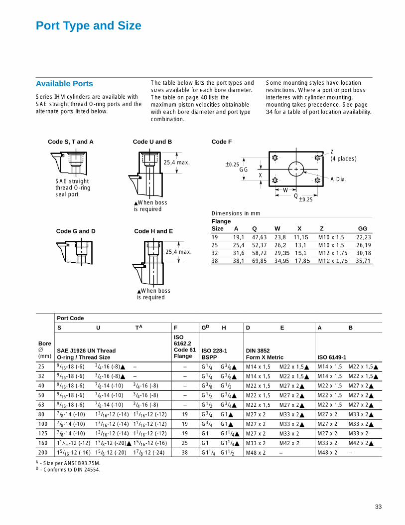
Port Type and Size
Available Ports
Series IHM cylinders are available withSAE straight thread O-ring ports and thealternate ports listed below.
The table below lists the port types andsizes available for each bore diameter.The table on page 40 lists themaximum piston velocities obtainablewith each bore diameter and port typecombination.
Some mounting styles have locationrestrictions. Where a port or port bossinterferes with cylinder mounting,mounting takes precedence. See page34 for a table of port location availability.
25,4 max.
25,4 max.
Code G and D Code H and E
Code S, T and A Code U and B
SAE straightthread O-ringseal port
�When bossis required
�When bossis required
FlangeSize A Q W X Z GG19 19,1 47,63 23,8 11,15 M10 x 1,5 22,2325 25,4 52,37 26,2 13,1 M10 x 1,5 26,1932 31,6 58,72 29,35 15,1 M12 x 1,75 30,1838 38,1 69,85 34,95 17,85 M12 x 1,75 35,71
Code F
XGG
A Dia.
Z(4 places)
QW
±0.25
±0.25
Dimensions in mm
Port Code
S U TA F GD H D E A B
Bore∅(mm)
SAE J1926 UN ThreadO-ring / Thread Size
ISO6162.2Code 61Flange
ISO 228-1BSPP
DIN 3852Form X Metric ISO 6149-1
25 9/16-18 (-6) 3/4-16 (-8)� – – G1/4 G3/8� M14 x 1,5 M22 x 1,5� M14 x 1,5 M22 x 1,5�
32 9/16-18 (-6) 3/4-16 (-8)� – – G1/4 G3/8� M14 x 1,5 M22 x 1,5� M14 x 1,5 M22 x 1,5�
40 9/16-18 (-6) 7/8-14 (-10) 3/4-16 (-8) – G3/8 G1/2 M22 x 1,5 M27 x 2� M22 x 1,5 M27 x 2�
50 9/16-18 (-6) 7/8-14 (-10) 3/4-16 (-8) – G1/2 G3/4� M22 x 1,5 M27 x 2� M22 x 1,5 M27 x 2�
63 9/16-18 (-6) 7/8-14 (-10) 3/4-16 (-8) – G1/2 G3/4� M22 x 1,5 M27 x 2� M22 x 1,5 M27 x 2�
80 7/8-14 (-10) 13/16-12 (-14) 11/16-12 (-12) 19 G3/4 G1� M27 x 2 M33 x 2� M27 x 2 M33 x 2�
100 7/8-14 (-10) 13/16-12 (-14) 11/16-12 (-12) 19 G3/4 G1� M27 x 2 M33 x 2� M27 x 2 M33 x 2�
125 7/8-14 (-10) 13/16-12 (-14) 11/16-12 (-12) 19 G1 G11/4� M27 x 2 M33 x 2 M27 x 2 M33 x 2
160 11/16-12 (-12) 15/8-12 (-20)� 15/16-12 (-16) 25 G1 G11/4� M33 x 2 M42 x 2 M33 x 2 M42 x 2�
200 15/16-12 (-16) 15/8-12 (-20) 17/8-12 (-24) 38 G11/4 G11/2 M48 x 2 – M48 x 2 –
A - Size per ANSI B93.75M.D - Conforms to DIN 24554.
34
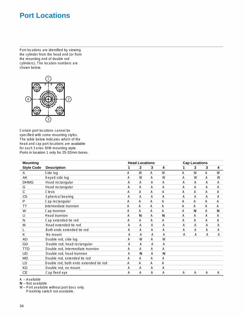
Port Locations
Port locations are identified by viewingthe cylinder from the head end (or fromthe mounting end of double rodcylinders). The location numbers areshown below.
3
1
24
Certain port locations cannot bespecified with some mounting styles.The table below indicates which of thehead and cap port locations are availablefor each Series IHM mounting style. Ports in location 1 only for 25-32mm bores.
Mounting Head Locations Cap LocationsStyle Code Description 1 2 3 4 1 2 3 4A Side lug A W A W A W A WAK Keyed side lug A W A W A W A WDHMG Head rectangular A A A A A A A AG Head rectangular A A A A A A A AC Clevis A A A A A A A ACS Spherical bearing A A A A A A A AP Cap rectangular A A A A A A A ATT Intermediate trunnion A A A A A A A AW Cap trunnion A A A A A N A NU Head trunnion A N A N A A A AN Cap extended tie rod A A A A A A A AM Head extended tie rod A A A A A A A AL Both ends extended tie rod A A A A A A A AK No mount A A A A A A A AAD Double rod, side lug A W A WGD Double rod, head rectangular A A A ATTD Double rod, intermediate trunnion A A A AUD Double rod, head trunnion A N A NMD Double rod, extended tie rod A A A ALD Double rod, both ends extended tie rod A A A AKD Double rod, no mount A A A ACE Cap fixed eye A A A A A A A A
A – AvailableN – Not availableW– Port available without port boss only.
Proximity switch not available.
35
Sealing Systems
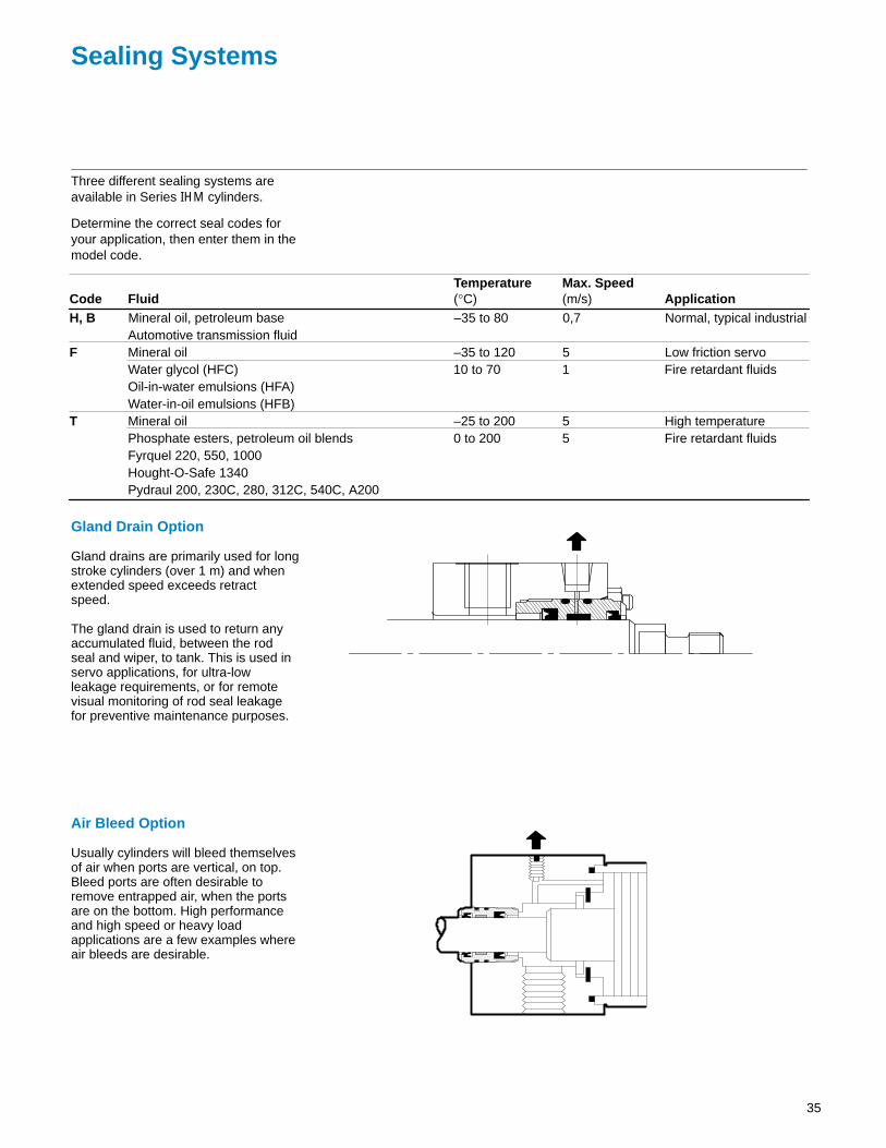
Three different sealing systems areavailable in Series IHM cylinders.
Determine the correct seal codes for your application, then enter them in themodel code.
Temperature Max. SpeedCode Fluid (°C) (m/s) ApplicationH, B Mineral oil, petroleum base –35 to 80 0,7 Normal, typical industrial
Automotive transmission fluidF Mineral oil –35 to 120 5 Low friction servo
Water glycol (HFC) 10 to 70 1 Fire retardant fluidsOil-in-water emulsions (HFA)Water-in-oil emulsions (HFB)
T Mineral oil –25 to 200 5 High temperaturePhosphate esters, petroleum oil blends 0 to 200 5 Fire retardant fluidsFyrquel 220, 550, 1000Hought-O-Safe 1340Pydraul 200, 230C, 280, 312C, 540C, A200
Gland Drain Option
Gland drains are primarily used for longstroke cylinders (over 1 m) and whenextended speed exceeds retractspeed.
The gland drain is used to return anyaccumulated fluid, between the rodseal and wiper, to tank. This is used inservo applications, for ultra-lowleakage requirements, or for remotevisual monitoring of rod seal leakagefor preventive maintenance purposes.
Air Bleed Option
Usually cylinders will bleed themselvesof air when ports are vertical, on top.Bleed ports are often desirable toremove entrapped air, when the portsare on the bottom. High performanceand high speed or heavy loadapplications are a few examples whereair bleeds are desirable.
36
Proximity Switches
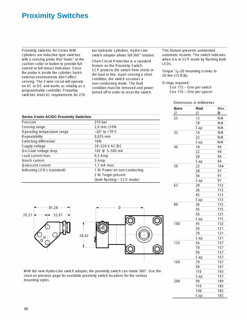
Proximity switches for Series IHMcylinders are inductive type switcheswith a sensing probe that “looks” at thecushion collar or button to provide fullextend or full retract indication. Sincethe probe is inside the cylinder, harshexternal environments don’t affectsensing. The 2-wire circuit will operateon AC or DC and works as reliably as aprogrammable controller. Proximityswitches meet UL requirements for 210
bar hydraulic cylinders. Hydro-Line switch adaptor allows full 360° rotation.
Short Circuit Protection is a standardfeature on the Proximity Switch.SCP protects the switch from shorts inthe load or line. Upon sensing a shortcondition, the switch assumes anon-conducting mode. The faultcondition must be removed and powerturned off in order to reset the switch.
This feature prevents unintendedautomatic restarts. The switch indicateswhen it is in SCP mode by flashing bothLEDs.
Torque 1/4–20 mounting screws to 20 Nm (15 ft-lb).
O-rings required:Size 115 – One per switchSize 116 – One per spacer
Series 2-wire AC/DC Proximity SwitchesPressure 210 barSensing range 2,0 mm ±10%Operating temperature range –20° to +70°CRepeatability 0,025 mmSwitching differential 10%Supply voltage 20–220 V AC/DCOn-State voltage drop 10V @ 5–500 mALoad current man. 0,5 AmpInrush current 3 AmpQuiescent current 1,7 mA max.Indicating LED’s (standard) 1 lit: Power on non-conducting
2 lit: Target present(both flashing = SCP mode)
Bore Rod Max.∅ ∅ D25 12 N/A
18 N/ACap N/A
32 14 N/A22 N/ACap N/A
40 18 9422 9428 94Cap 94
50 22 10428 9736 97Cap 97
63 28 11336 11345 113Cap 113
80 36 11545 11556 121Cap 115
100 45 13256 12170 121Cap 121
125 56 15770 15790 157Cap 157
160 70 15790 167110 165Cap 157
200 90 189110 182140 182Cap 182
58,42
D
52,0729,21
81,28
With the new Hydro-Line switch adaptor, the proximity switch can rotate 360°. Use thechart on previous page for available proximity switch locations for the variousmounting styles.
Dimensions in millimetres

37
Application / Engineering Data
Stop Tube Selection
The following table lists the maximumstroke permissible without the use of astop tube. Strokes are listed for rigidmounting styles as well as clevis andtrunnion pivot mounts.
As the stroke length of a cylinderincreases, the resultant bearing loadson the piston rod become greater. Tokeep these bearing loads fromexceeding design limitations, and toobtain optimum life from a cylinder, stoptubes should be specified according tothe following procedure:
To order a stop tube, enter an X suffixin the model code. Then specify thecylinder’s working stroke and therequired stop tube length. Specify 25mm of stop tube for each 250 mm (orfraction thereof) of stroke in excessof the maximums listed in the table.
Bore Maximum Stroke (mm)∅ Pivot Rigid mounts(mm) Mounts Unsupported Rod Supported Rod
25 500 600 100032 500 600 100040 600 750 120050 600 750 120063 750 965 120080 750 965 1200
100 750 965 1200125 900 1000 1200160 900 1000 1200200 900 1000 1200
Stop Tube Designs
Three typical stop tube designs areillustrated below.
Design A
Used for cylinders not cushioned on therod end.
É
Design B
Used for cushioned hydraulic cylinders.
ÉÉ
Design C
The best choice for a cylinder with anexceptionally long stop tuberequirement. Note that the piston’seffective bearing area is doubled, inaddition to gaining the normal increased
minimum distance between bearingpoints.
ÉÉÉÉ
ÉÉ
Tie Rod Spacers andCenter Supports
A tie rod spacer or center supportshould be applied when the strokelength exceeds 20 times the borediameter.
Tie rod spacer
Tie rod spacers and center supports areused to improve the structural rigidity oflong stroke tie rod cylinders.
The spacers have through holes for thetie rods and are held in place on thecylinder barrel with a small tack weld orset screw.
The spacer keeps the tie rod in theproper position around the centerline ofthe cylinder and acts much like a trussin preventing excessive deflection in along stroke cylinder that is not rigidlymounted (clevis mount, etc.).
Through tie rods
Tie rod center support
The center support has side mountinglugs similar to side lug mount heads andserves as an additional mountinglocation. The tie rods are threaded intothe center support and it becomes aload-carrying component of the cylinderassembly.
The exact location of the tie rod centersupport is generally optional, whichgreatly increases the flexibility inmounting a long stroke cylinder.
Mounting lug similarto Style IHMA
Tapped tie rods
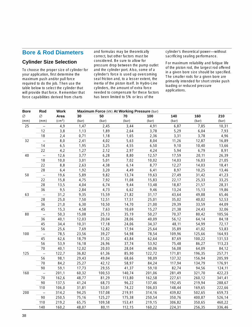
38
Bore & Rod Diameters
Cylinder Size Selection
To choose the proper size of cylinder foryour application, first determine themaximum push and/or pull forcerequired to do the job. Then use thetable below to select the cylinder thatwill provide that force. Remember thatforce capabilities derived from charts
and formulas may be theoreticallycorrect, but other factors must beconsidered. Be sure to allow forpressure drop between the pump outletand the cylinder port. Also, some of acylinder’s force is used up overcomingseal friction and, to a lesser extent, theinertia of the piston itself. In Hydro-Linecylinders, the amount of extra forceneeded to compensate for these factorshas been limited to 5% or less of the
cylinder’s theoretical power––withoutsacrificing sealing performance.
For maximum reliability and fatigue lifeof the piston rod, the largest rod offeredin a given bore size should be specified.The smaller rods for a given bore areprimarily intended for short stroke pushloading or reduced pressureapplications.
Bore Rod Work Maximum Force (kN) At Working Pressure (bar)
∅ ∅ Area 30 50 70 100 140 160 210(mm) (mm) (cm2) (bar) (bar) (bar) (bar) (bar) (bar) (bar)
25 – 4,9 1,47 2,45 3,44 4,91 6,87 7,85 10,3112 3,8 1,13 1,89 2,64 3,78 5,29 6,04 7,9318 2,4 0,71 1,18 1,65 2,36 3,31 3,78 4,96
32 – 8,0 2,41 4,02 5,63 8,04 11,26 12,87 16,8914 6,5 1,95 3,25 4,55 6,50 9,10 10,40 13,6622 4,2 1,27 2,12 2,97 4,24 5,94 6,79 8,91
40 – 12,6 3,77 6,28 8,80 12,57 17,59 20,11 26,3918 10,0 3,01 5,01 7,02 10,02 14,03 16,03 21,0522 8,8 2,63 4,38 6,14 8,77 12,27 14,03 18,4128 6,4 1,92 3,20 4,49 6,41 8,97 10,25 13,46
50 – 19,6 5,89 9,82 13,74 19,63 27,49 31,42 41,2322 15,8 4,75 7,92 11,08 15,83 22,17 25,33 33,2528 13,5 4,04 6,74 9,44 13,48 18,87 21,57 28,3136 9,5 2,84 4,73 6,62 9,46 13,24 15,13 19,86
63 – 31,2 9,35 15,59 21,82 31,17 43,64 49,88 65,4628 25,0 7,50 12,51 17,51 25,01 35,02 40,02 52,5336 21,0 6,30 10,50 14,70 21,00 29,39 33,59 44,0945 15,3 4,58 7,63 10,69 15,27 21,38 24,43 32,06
80 – 50,3 15,08 25,13 35,19 50,27 70,37 80,42 105,5636 40,1 12,03 20,04 28,06 40,09 56,12 64,14 84,1845 34,4 10,31 17,18 24,06 34,37 48,11 54,99 72,1756 25,6 7,69 12,82 17,94 25,64 35,89 41,02 53,83
100 – 78,5 23,56 39,27 54,98 78,54 109,96 125,66 164,9345 62,6 18,79 31,32 43,84 62,64 87,69 100,22 131,5356 53,9 16,18 26,96 37,74 53,92 75,48 86,27 113,2370 40,1 12,02 20,03 28,04 40,06 56,08 64,09 84,12
125 – 122,7 36,82 61,36 85,90 122,72 171,81 196,35 257,7156 98,1 29,43 49,04 68,66 98,09 137,32 156,94 205,9970 84,2 25,27 42,12 58,97 84,24 117,94 134,79 176,9190 59,1 17,73 29,55 41,37 59,10 82,74 94,56 124,11
160 – 201,1 60,32 100,53 140,74 201,06 281,49 321,70 422,2370 162,6 48,77 81,29 113,80 162,58 227,61 260,12 341,4190 137,5 41,24 68,73 96,22 137,46 192,45 219,94 288,67
110 106,0 31,81 53,01 74,22 106,03 148,44 169,65 222,66200 – 314,2 94,25 157,08 219,91 314,16 439,82 502,65 659,73
90 250,5 75,16 125,27 175,38 250,54 350,76 400,87 526,14110 219,2 65,75 109,58 153,41 219,15 306,82 350,65 460,22140 160,2 48,07 80,11 112,15 160,22 224,31 256,35 336,46

39
Maximum AllowablePush Strokes
In push applications, a cylinder acts as aloaded column. There are two basicways to measure the column length.
Pivot mounts: The length is measured from the pivotpoint to the end of the rod in the fullyextended position.
Flange and other rigid mounts: The exposed piston rod is considered tobe the column length with a fixed end atthe cylinder which allows longer strokes.
To use the table below, first go to thesection for your mounting style. Thenlocate the column which is closest to,but not below, your application’soperating pressure. The intersection of
operating pressure and bore/rod sizerepresents the maximum allowable pushstroke. This maximum stroke is basedon column loading analysis only anddoes not consider side loading, stoptube requirements or other cylinderstroke limiters.
For pressures above 210 bar, consultyour local Hydro-Line representative.
Maximum Stroke (mm) at Working Pressure (bar)
Rigid Mounts (A, AK, CE, G, Cap Swivel Mounts Trunnion MountsBORE ROD L, M, N, P, AD, GD, LD, and MD) (C, CS, and W) (TT, TTD, U, and UD)
∅ ∅ 30 50 70 100 160 210 30 50 70 100 160 210 30 50 70 100 160 210(mm) (mm) (bar) (bar) (bar) (bar) (bar) (bar) (bar) (bar) (bar) (bar) (bar) (bar) (bar) (bar) (bar) (bar) (bar) (bar)
25 12 758 566 460 361 243 175 337 252 205 161 108 78 404 302 246 193 130 9418 1754 1339 1114 910 684 569 780 595 495 405 304 253 936 714 595 486 365 304
32 14 797 591 475 366 230 145 355 263 211 163 102 64 425 315 254 195 123 7722 2042 1556 1293 1054 787 651 908 692 575 469 350 289 1090 831 690 562 420 347
40 18 1058 786 635 491 317 211 471 350 282 219 141 94 565 419 339 262 169 11222 1612 1216 999 799 569 446 717 541 444 355 253 198 860 649 533 426 304 23828 2649 2020 1680 1370 1025 850 1178 898 747 609 456 378 1414 1078 896 731 547 454
50 22 1261 935 753 580 367 234 561 416 335 258 163 104 673 499 402 309 196 12528 2091 1579 1299 1041 745 588 930 702 578 463 331 261 1116 843 693 556 398 31436 3508 2677 2228 1820 1367 1138 1560 1191 991 810 608 506 1872 1429 1189 971 730 607
63 28 1623 1204 971 750 479 311 722 536 432 333 213 138 866 643 518 400 255 16636 2748 2077 1711 1374 989 785 1222 924 761 611 440 349 1466 1109 913 733 528 41945 4348 3318 2761 2254 1691 1407 1934 1475 1228 1003 752 626 2321 1771 1473 1203 903 751
80 36 2116 1572 1269 983 634 422 941 699 564 437 282 187 1129 839 677 525 338 22545 3377 2551 2099 1683 1206 953 1502 1134 934 748 536 424 1802 1361 1120 898 644 50856 5298 4040 3359 2740 2050 1701 2356 1797 1494 1219 912 756 2827 2156 1793 1462 1094 908
100 45 2645 1965 1587 1229 792 527 1176 874 706 546 352 234 1412 1049 847 656 423 28156 4183 3158 2599 2082 1490 1175 1860 1405 1156 926 663 523 2232 1686 1387 1111 795 62770 6623 5050 4199 3425 2563 2126 2945 2246 1867 1523 1140 945 3534 2695 2241 1828 1368 1134
125 56 3275 2432 1963 1518 976 644 1457 1082 873 675 434 286 1748 1298 1047 810 521 34470 5228 3948 3248 2603 1863 1469 2325 1756 1445 1158 828 653 2790 2107 1733 1389 994 78490 8769 6693 5571 4551 3418 2846 3900 2976 2477 2024 1520 1266 4680 3572 2973 2429 1824 1519
160 70 3986 2953 2376 1828 1151 724 1773 1313 1057 813 512 322 2127 1576 1268 975 614 38690 6754 5102 4199 3366 2412 1905 3004 2269 1867 1497 1073 847 3605 2723 2241 1796 1287 1017
110 10212 7782 6467 5269 3933 3254 4542 3461 2876 2343 1749 1447 5450 4153 3451 2812 2099 1736200 90 5290 3930 3173 2457 1584 1054 2353 1748 1411 1093 705 469 2823 2097 1693 1311 846 562
110 8058 6079 4995 3995 2844 2228 3584 2703 2222 1777 1265 991 4300 3244 2666 2132 1518 1189140 13245 10100 8398 6850 5126 4252 5890 4491 3735 3046 2279 1891 7068 5390 4482 3656 2735 2269

40
Port Selection
Use this table to determine which borediameter, rod diameter, and portcombination will provide the pistonvelocity required for your application.
Fluid Port Codes Port CodesReq. per Port Code S B, E and U A, D, F, and T Port Code G Port Code H
Bore Rod 10 mm of Piston Piston Piston Piston Piston∅ ∅ of Stroke Flow Velocity Flow Velocity Flow Velocity Flow Velocity Flow Velocity(mm) (mm) (l) (l/min) (m/s) (l/min) (m/s) (l/min) (m/s) (l/min) (m/s) (l/min) (m/s)
25 Cap 0,0049 13,4 0,46 23,2 0,79 13,4 0,46 4,5 0,15 13,4 0,4612 0,0038 13,4 0,59 23,2 1,02 13,4 0,59 4,5 0,20 13,4 0,5918 0,0024 13,4 0,94 23,2 1,64 13,4 0,94 4,5 0,32 13,4 0,94
32 Cap 0,0080 13,4 0,28 23,2 0,48 13,4 0,28 4,5 0,09 13,4 0,2814 0,0065 13,4 0,34 23,2 0,60 13,4 0,34 4,5 0,12 13,4 0,3422 0,0042 13,4 0,53 23,2 0,91 13,4 0,53 4,5 0,18 13,4 0,53
40 Cap 0,0126 13,4 0,18 35,6 0,47 23,2 0,31 13,4 0,18 23,2 0,3118 0,0100 13,4 0,22 35,6 0,59 23,2 0,39 13,4 0,22 23,2 0,3922 0,0088 13,4 0,25 35,6 0,68 23,2 0,44 13,4 0,25 23,2 0,4428 0,0064 13,4 0,35 35,6 0,93 23,2 0,60 13,4 0,35 23,2 0,60
50 Cap 0,0196 13,4 0,11 35,6 0,30 23,2 0,20 23,2 0,20 56,4 0,4822 0,0158 13,4 0,14 35,6 0,38 23,2 0,24 23,2 0,24 56,4 0,5928 0,0135 13,4 0,17 35,6 0,44 23,2 0,29 23,2 0,29 56,4 0,7036 0,0095 13,4 0,24 35,6 0,63 23,2 0,41 23,2 0,41 56,4 0,99
63 Cap 0,0312 13,4 0,07 35,6 0,19 23,2 0,12 23,2 0,12 56,4 0,3028 0,0250 13,4 0,09 35,6 0,24 23,2 0,16 23,2 0,16 56,4 0,3836 0,0210 13,4 0,11 35,6 0,28 23,2 0,18 23,2 0,18 56,4 0,4545 0,0153 13,4 0,15 35,6 0,39 23,2 0,25 23,2 0,25 56,4 0,62
80 Cap 0,0503 35,6 0,12 78,6 0,26 56,4 0,19 56,4 0,19 108,3 0,3636 0,0401 35,6 0,15 78,6 0,33 56,4 0,23 56,4 0,23 108,3 0,4545 0,0344 35,6 0,17 78,6 0,38 56,4 0,27 56,4 0,27 108,3 0,5356 0,0256 35,6 0,23 78,6 0,51 56,4 0,37 56,4 0,37 108,3 0,70
100 Cap 0,0785 35,6 0,08 78,6 0,17 56,4 0,12 108,3 0,12 108,3 0,2345 0,0626 35,6 0,10 78,6 0,21 56,4 0,15 108,3 0,29 108,3 0,2956 0,0539 35,6 0,11 78,6 0,24 56,4 0,17 108,3 0,33 108,3 0,3370 0,0401 35,6 0,15 78,6 0,33 56,4 0,24 108,3 0,45 108,3 0,45
125 Cap 0,1227 35,6 0,05 78,6 0,11 108,3 0,15 108,3 0,15 176,6 0,2456 0,0981 35,6 0,06 78,6 0,13 108,3 0,18 108,3 0,18 176,6 0,3070 0,0842 35,6 0,07 78,6 0,16 108,3 0,21 108,3 0,21 176,6 0,3590 0,0591 35,6 0,10 78,6 0,22 108,3 0,30 108,3 0,30 176,6 0,50
160 Cap 0,2011 56,4 0,05 176,6 0,15 108,3 0,09 108,3 0,09 176,6 0,1570 0,1626 56,4 0,06 176,6 0,18 108,3 0,11 108,3 0,11 176,6 0,1890 0,1375 56,4 0,07 176,6 0,21 108,3 0,13 108,3 0,13 176,6 0,21
110 0,1060 56,4 0,09 176,6 0,28 108,3 0,17 108,3 0,17 176,6 0,28200 Cap 0,3142 108,3 0,06 176,6 0,09 261,7 0,14 176,6 0,09 261,7 0,14
90 0,2505 108,3 0,07 176,6 0,12 261,7 0,17 176,6 0,12 261,7 0,17110 0,2192 108,3 0,08 176,6 0,13 261,7 0,20 176,6 0,13 261,7 0,27140 0,1602 108,3 0,11 176,6 0,18 261,7 0,27 176,6 0,18 261,7 0,27

41
Cushioning System
Hydro-Line cylinders have standardfeatures that are extra cost options ornot available on other look-alikeISO/DIN cylinders. IHM Series hydrauliccylinders are available with a patentedfloating ring cushion seal or alternatesolid design with check valve thatprovide positive cushion sealing withminimum wear and maximum pistonacceleration on the return stroke.
Advanced CushionsProvide Faster Cycle Times
Cylinder cushions are designed todecelerate the piston velocity near theend of each cylinder stroke to preventexcessive mechanical shock.
To accomplish this, the cushion collarcontacts a floating sleeve or cylinderhead which permits a very close sealcontact without high loading. The sleeveseats against the head and provides avery effective seal to trap the fluid.Consistent performance and long lifeare provided.
Hydro-Line advanced cushions permithigher cylinder speed, shorter cycletime, and more work per hour.
The sleeve design is also free to movein an axial direction and functions as afluid check. When the fluid flow isreversed, the sleeve moves off its seat,and fluid flows around the slots in theouter sleeve’s diameter permitting nearlyfull flow for quick acceleration.
Cushion Features
� Cushion design provides consistentlong wearing seal between cushioncollar and head.
� Floating design self-aligns to minimizewear.
� Check valve action of sleeve providesrapid acceleration out of the cushion.
Typical Straight Cushion
Hydro-Line SolidProfiled Cushion
TheoreticalIdealCushion
Cushion Travel
Cu
shio
n P
ress
ure
Cushions are recommended whenpiston speed exceeds 0,13 m/s. Anyheavy loads attached to the piston rodshould be absorbed by external meanssuch as shock absorbers or springs.
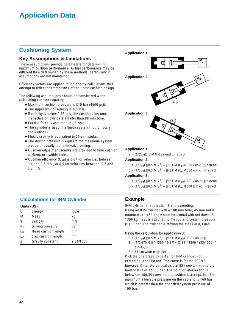
42
Application Data
Units (US)E Energy jouleM Mass kgV Velocity m/sPd Driving pressure barLH Head cushion length mmLC Cap cushion length mmg Gravity constant 9,81/1000
MKey Assumptions & LimitationsThese assumptions provide parameters for determiningmaximum cushion performance. Actual performance may bedifferent than determined by these methods, particularly ifassumptions are not maintained.
Efficiency factors are applied to the energy calculations thatattempt to reflect characteristics of the Eaton cushion design.
The following assumptions should be considered whencalculating cushion capacity:
� Maximum cushion pressure is 310 bar (4500 psi).� The upper limit of velocity is 0.5 m/s.� If velocity is below 0,13 m/s, the cushions become
ineffective on cylinders smaller than 80 mm bore.� Friction force is assumed to be zero.� The cylinder is used in a linear system (not for rotary
applications).� Fluid viscosity is equivalent to 25 centistoke.� The driving pressure is equal to the maximum system
pressure, usually the relief valve setting.� Cushion adjustment screws are provided to tune cushion
performance within limits.� Cushion efficiency (Ceff) is 0.67 for velocities between
0,1 and 0,3 m/s., or 0,5 for velocities between 0,3 and 0,5 m/s.
Calculations for IHM Cylinder
Application 1:
E = (1/Ceff)[0,5 M V2] extend or retract
Application 2:
E = (1/Ceff) �[0.5 M V2] – [9,81 M (Lhc/1000 (sin α) ]� extend
E = (1/Ceff) �[0.5 M V2] + [9,81 M (Lcc/1000 (sin α) ]� retract
Application 3:
E = (1/Ceff) �[0.5 M V2] + [9,81 M (Lhc/1000 (sin α) ]� extend
E = (1/Ceff) �[0.5 M V2] – [9,81 M (Lcc/1000 (sin α) ]� retract
α
M
α
M
Application 1
Application 2
Application 3
ExampleIHM cylinder in application 3 and extending:Using an IHM cylinder with a 100 mm bore, 45 mm rod ismounted at a 45� angle from horizontal with rod down. A1300 kg mass is attached to the rod and system pressureis 100 bar. The cylinder is moving the mass at 0,3 m/s.
Using the calculation for application 3:E = (1/Ceff) �[0.5 M V2] + [9,81 M (Lhc/1000 (sin α) ]�E = (1/0.67)�[0.5 * 1300 * 0,32] + [9,81 * 1300 * (33/1000) * sin(45)]�E = 531 newton-m (joule)
Pick the chart (see page 43) for IHM cylinder, rodextending, and first rod. The curve is for the 100/45bore/rod. Enter the vertical axis at 531 newton-m and thehorizontal axis at 100 bar. The point of intersection isbelow the 100/45 curve so the cushion is acceptable. Themaximum allowable pressure on the cap end is 160 barwhich is greater than the specified system pressure of100 bar.
Cushioning System
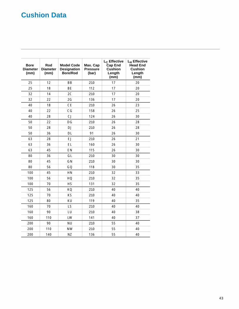
43
Cushion Data
Bore Diameter
(mm)
RodDiameter
(mm)
Model CodeDesignation
Bore/Rod
Max. CapPressure
(bar)
LC EffectiveCap EndCushionLength(mm)
LH EffectiveHead EndCushionLength(mm)
25 12 BB 210 17 20
25 18 BE 112 17 20
32 14 2C 210 17 20
32 22 2G 136 17 20
40 18 CE 210 26 23
40 22 CG 158 26 25
40 28 CJ 124 26 30
50 22 DG 210 26 28
50 28 DJ 210 26 28
50 36 DL 91 26 30
63 28 EJ 210 26 21
63 36 EL 160 26 30
63 45 EN 115 26 30
80 36 GL 210 30 30
80 45 GN 210 30 30
80 56 GQ 118 30 35
100 45 HN 210 32 33
100 56 HQ 210 32 35
100 70 HS 131 32 35
125 56 KQ 210 40 40
125 70 KS 210 40 40
125 80 KU 119 40 35
160 70 LS 210 40 40
160 90 LU 210 40 38
160 110 LW 141 40 37
200 90 NU 210 55 40
200 110 NW 210 55 40
200 140 NZ 136 55 40

44
Energy Absorbing Potential Charts
IHM Cap Cushion - Rod RetractingFirst Rod
Ene
rgy
Abs
orbi
ng P
oten
tial –
Jou
le
IHM Rod Cushion - Rod ExtendingFirst Rod
0 40 80 120 160 20010
100
1000
10000
100000
Driving Pressure – bar
25/12
Bore/Rod
32/14
40/1850/22
63/28
80/36
100/45
125/56
160/70
200/90
0 40 80 120 160 20010
100
1000
10000
100000
Driving Pressure – bar
25/12
Bore/Rod
32/14
40/18
50/22
63/28 80/36
100/45
125/56
160/70200/90
Ene
rgy
Abs
orbi
ng P
oten
tial –
Jou
le

45
IHM Cap Cushion - Rod RetractingSecond Rod
IHM Rod Cushion - Rod ExtendingSecond Rod
0 40 80 120 160 20010
100
1000
10000
100000
Driving Pressure – bar
25/18
Bore/Rod
32/22
40/2250/28
63/36
80/45
100/56
125/70
160/90
200/110
Ene
rgy
Abs
orbi
ng P
oten
tial –
Jou
le
Ene
rgy
Abs
orbi
ng P
oten
tial –
Jou
le
0 40 80 120 160 20010
100
1000
10000
100000
Driving Pressure – bar
25/18
40/22
63/36
100/56
200/110
160/90
125/70
80/45
50/28
32/22

46
IHM Cap Cushion - Rod RetractingThird Rod
IHM Rod Cushion - Rod ExtendingThird Rod
0 40 80 120 160 20010
100
1000
10000
100000
Driving Pressure – bar
Bore/Rod
40/28
50/36
63/45
80/56
100/70
125/90
160/110
200/140
Ene
rgy
Abs
orbi
ng P
oten
tial –
Jou
le
0 40 80 120 160 20010
100
1000
10000
100000
Driving Pressure – bar
40/28
80/56
100/70
Ene
rgy
Abs
orbi
ng P
oten
tial –
Jou
le
50/36
160/110
200/140
63/45
125/90

47
Weights
The following table lists approximate netweights of Series IHM cylinders.
Weights shown are based on cylinderswith standard rod diameter and singlerod end. All weights are expressed inkilograms.
Double rod cylinder weight is equal to1,15 times chart weight plus weight dueto stroke.
Zero Length Weight (kg) Single Rod Double RodIHMA Weight Weight
Bore Rod IHMCS IHMAK IHMG IHMW per mm of per mm of∅ ∅ IHMN IHMC IHMP IHMU Stroke Stroke(mm) (mm) IHMM IHMCE IHMTT IHML (kg) (kg)
25 12 1,2 1,2 1,7 1,2 0,004 0,005 32 14 1,6 1,6 2,2 1,6 0,006 0,007 40 18 3,5 3,7 4,9 3,6 0,009 0,011 50 22 5,3 5,5 7,3 5,5 0,013 0,016 63 28 7,4 7,8 10,4 7,7 0,019 0,024 80 36 14,2 14,9 19,9 14,7 0,031 0,039100 45 19,2 20,2 26,9 20,0 0,046 0,058125 56 37,6 39,5 47,4 39,1 0,074 0,093160 70 61,6 64,7 77,6 64,0 0,113 0,143200 90 113,0 118,6 142,4 117,5 0,158 0,208
Approximate Cylinder Weights

Double Lip Rod WipersA double lip Rod Wiper pro-vides increased rod seal lifeby removing abrasive conta-mination from the rod insevere applications.
Rod BootA boot surrounds the pistonrod with an external, expand-able cover to protect the rodsurface from external contam-ination. Requires additionalrod length which is deter-mined by the cylinderstroke.
IHM Series Standard Design Options
48
IHM
Special Rod EndsModifications of standard rod ends or completely specialrod end styles are available to meet unique rod end con-nection requirements.
Special PortsMetric, NPTF, SAE, Manifold, Flange and other portingoptions are available to meet specific requirements.
Electronic FeedbackA complete line of precision cylinder position sensing andfeedback devices are available. These packaged cylindersystems can handle virtually any application requiringfeedback throughout the cylinder stroke — pneumatic orhydraulic, large or small bore, long or short strokes, withor without velocity monitoring — with resolutions of±0.00004mm or better. (See the Hydro-Line SystemsCylinder Catalog).
Stainless Steel Piston RodsChrome plated piston rods in 17-4 PH stainless steelare available for those applications requiring increasedcorrosion resistance.
Special Coating and PaintingCylinders can be prepared with a primer coat or epoxy,lacquer, or enamel paint finish coatings to customer spec-ifications. Synergistic, Nitrocarburizing and other materialtreatments are also available for special applications.
PlatingElectroless Nickel, Cadmium and other plating finishes areavailable for corrosive, washdown, pharmaceutical, andother applications.
Special MaterialsBronze, brass, aluminum, stainless steel, or other specialmaterials are available to meet most unique materialrequirements.
Rod WearbandsRod wearbands fitted to therod cartridge eliminate metal-to-metal contact on the car-tridge/rod O.D. Bronze-filledTeflon wearband materialreduces friction and wear in applications where side-load is present.
Air BleedersBleeders are located in thehead and cap when specified,.bleed screws are captive and may be located in positions 1, 2, 3, or 4.

IHM Series Cylinder Types
Back-to-Back CylindersBack-to-back cylinders are two single rod cylinders mount-ed together at the caps. Combinations of positions (3 posi-tions) are possible through various combinations of pistonactuation.
Spring Return/Extend CylindersSpring Return/Extend Cylinders provide thrust in one directiononly (can be either direction). One port is used for pressureto act against the load while the inactive port is vented. Aninternal spring is used to return the cylinder to its normalposition.
Pumping UnitsPumping units consist of a standard hydraulic cylindercoupled with a volume displacing lance cylinder via tie-bars.Special seals and lance surface treatments are availableto provide compatibility with resins and chemicals used inthe pumping process. Single and double ended designsare available.
Systems CylindersSystems cylinders integrate electronics with hydraulicsand pneumatics to provide precision cylinder sensing andfeedback. Internal magnetostrictive or linear potentiometertransducers are added to the cylinder. Valve manifoldblocks can also be added to provide a compact feedbackcylinder package. (See Hydro-Line Systems Catalogue.)
Multiple Position CylindersMultiple position cylinders are similar to tandem cylinders(except that the piston and rod assemblies are not con-nected) in that the output force is increased. Additionally,they may act as a precision multiple positioning device byactuating each cylinder successively or independently.
Single/Double Acting Cylinde r Standard HM Series cylinders are double acting, with fluidpower driving the piston in both directions. Single actingcylinders have fluid power driving the piston in one direc-tion, relying on either the load or an external force to returnthe piston after the pressure is released.
Double End Cylinders Back-to-BackDouble end cylinders mounted back-to-back have commonpiston rod and tie rods and the same stroke length.
Tandem CylindersTandem Cylinders consist of two cylinders interconnected(piston and rod assemblies are connected). Pressure canact on two effective piston areas allowing the cylinder tobe used as a force multiplier. This type of cylinder can alsobe used in air/oil systems to provide smooth, metered flowbecause of equal volumes in one chamber of both cylin-ders.
49
IHM

Eaton’s full line of cylinder products and options fit most customers’ application requirements, however, a specialcylinder is often required to meet custom specifications. These custom cylinders are often needed to solve dif-ficult application problems, upgrade existing equipment or are designed into new machinery.
Eaton’s Sales, Engineering and Manufacturing groups are cylinder specialists and have many years of expe-rience in the interpretation of requirements, design and manufacture of custom cylinder products.
Our capabilities include:• Bore diameters to 760mm
• Stroke lengths to 7600mm
• Operating pressures to700 bar or higher
• Operating mediums rangingfrom shop air to nitrogen,or from standard hydraulicfluid to special syntheticfluids
• Tie rod, welded, threaded,and bolted cylinder con-struction
• Finite element analysis
• Application simulation inour testing laboratories
Adjustable Stroke CylindersAdjustable stroke cylinders are furnished with a strokeadjusting screw in the cap end of the cylinder. Adjustingthis screw in or out limits the retract stroke to the preciselength desired.
Non-Rotating CylindersNon-rotating cylinders are furnished with internal guiderods which prevent piston rod rotation throughout thestroke. Rotational torque and stroke length determine theamount and diameter of the guide rods.
Custom CylindersFor Special Applications
Eaton would appreciate an opportunity to submit a proposal to solve your application problem or fulfill yourcurrent cylinder requirements. Simply copy and complete the Application Data Sheet on the following page and faxto Eaton or an authorized Hydro-Line distributor.
= Solutions
50
IHM

51
Hydro-Line Cylinders Application Data Sheet
FRM-24-011, 8/01
PREPARED BY: DATE: REVIEWED BY: DATE:
CUSTOMER DRAWING NUMBER: REVISION DATES: HYDRO-LINE QUOTE NUMBER:
APPLICATION SKETCH: DESCRIPTION OF APPLICATIONOR SPECIAL REQUIREMENT:
WHAT INDUSTRY IS THE CYLINDER WHAT TYPE OF MACHINE IS THE WHAT IS THE CYLINDER NAMEUSED IN? CYLINDER USED ON? THE APPLICATION?
WHAT IS THE PRESENT PROBLEM?
WHAT IS THE PRESENT CYLINDER TYPE AND MODEL NUMBER?
WHAT ENVIRONMENTAL CONDITIONS IS THE CYLINDER SUBJECTED TO?
Standard Factory Corrosive Washdown Chemical? Outdoors Other
WHAT IS THE MOUNTING?Attitude Rod End Connection Known Side LoadVertical Angle Horizontal Firmly Guided
Degrees From Vertical Supported lbs.Rod Up Rod Up Unsupported Rod Down Rod Down
WHAT IS THE OPERATING ENVIRONMENT?Fluid Media Operating Pressure Temperature at CylinderAir Minimum psi Minimum °FOil Typical psi Typical °FOther Maximum psi Maximum °FFluid Type
WHAT IS THE WORK BEING PERFORMED?Load Rod Speed Cycles per MinutePush lbs. Extend in./sec.Pull lbs. Retract in./sec. (in and out)
Company Name:
Contact:
Phone Number: Fax Number:
Distributor Name:
Contact:
Phone Number: Fax Number: ______________
Model Numbering System
Stop Tube Length Trunnion XI Dimension Stainless Steel Rod TypeHEAD CAP HEAD CAP HEAD CAP
DOUBLE END ADDITIONAL NEEDLE BRONZE DRAIN- IND. MODELROD STYLE ROD LENGTH LOCATION KEYPLATE 4-FLAT BLEEDERS BUSHING BACK SWITCH PREFIX
MODEL/SERIES MOUNT BORE STROKE CUSHION ROD DIA ROD STY PORTS ROD PSTN H C MODEL
• • •
QUANTITY
C C
Please fill in all available information above. Refer to the Hydro-Line Model Numbering System on Pages 2.
SEALS PORT LOC
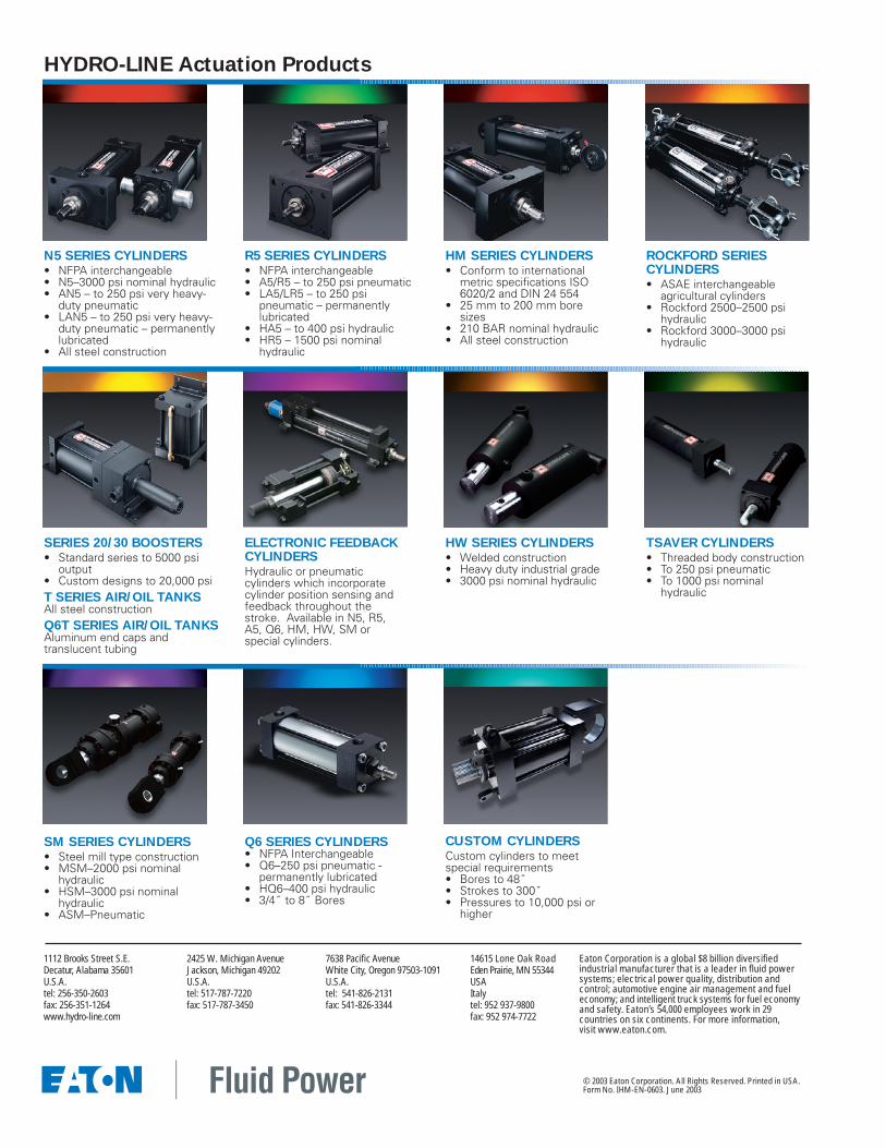
HYDRO-LINE Actuation Products
HM SERIES CYLINDERS• Conform to international
metric specifications ISO6020/2 and DIN 24 554
• 25 mm to 200 mm boresizes
• 210 BAR nominal hydraulic• All steel construction
ROCKFORD SERIES CYLINDERS• ASAE interchangeable
agricultural cylinders• Rockford 2500–2500 psi
hydraulic• Rockford 3000–3000 psi
hydraulic
ELECTRONIC FEEDBACKCYLINDERSHydraulic or pneumatic cylinders which incorporatecylinder position sensing andfeedback throughout thestroke. Available in N5, R5,A5, Q6, HM, HW, SM or special cylinders.
SERIES 20/30 BOOSTERS• Standard series to 5000 psi
output• Custom designs to 20,000 psi T SERIES AIR/OIL TANKSAll steel constructionQ6T SERIES AIR/OIL TANKSAluminum end caps and translucent tubing
N5 SERIES CYLINDERS• NFPA interchangeable• N5–3000 psi nominal hydraulic• AN5 – to 250 psi very heavy-
duty pneumatic• LAN5 – to 250 psi very heavy-
duty pneumatic – permanentlylubricated
• All steel construction
R5 SERIES CYLINDERS• NFPA interchangeable • A5/R5 – to 250 psi pneumatic• LA5/LR5 – to 250 psi
pneumatic – permanentlylubricated
• HA5 – to 400 psi hydraulic• HR5 – 1500 psi nominal
hydraulic
CUSTOM CYLINDERSCustom cylinders to meet special requirements• Bores to 48˝• Strokes to 300˝• Pressures to 10,000 psi or
higher
HW SERIES CYLINDERS• Welded construction• Heavy duty industrial grade• 3000 psi nominal hydraulic
TSAVER CYLINDERS• Threaded body construction• To 250 psi pneumatic• To 1000 psi nominal
hydraulic
SM SERIES CYLINDERS• Steel mill type construction• MSM–2000 psi nominal
hydraulic• HSM–3000 psi nominal
hydraulic• ASM–Pneumatic
Q6 SERIES CYLINDERS• NFPA Interchangeable• Q6–250 psi pneumatic -
permanently lubricated• HQ6–400 psi hydraulic• 3/4˝ to 8˝ Bores
1112 Brooks Street S.E.Decatur, Alabama 35601U.S.A.tel: 256-350-2603fax: 256-351-1264www.hydro-line.com
14615 Lone Oak RoadEden Prairie, MN 55344USAItalytel: 952 937-9800fax: 952 974-7722
2425 W. Michigan AvenueJackson, Michigan 49202U.S.A.tel: 517-787-7220fax: 517-787-3450
7638 Pacific AvenueWhite City, Oregon 97503-1091U.S.A.tel: 541-826-2131fax: 541-826-3344
© 2003 Eaton Corporation. All Rights Reserved. Printed in USA.Form No. IHM-EN-0603. June 2003
Eaton Corporation is a global $8 billion diversifiedindustrial manufacturer that is a leader in fluid powersystems; electrical power quality, distribution andcontrol; automotive engine air management and fueleconomy; and intelligent truck systems for fuel economyand safety. Eaton’s 54,000 employees work in 29 countries on six continents. For more information, visit www.eaton.com.