hydrocarbon refrigerant leaks into car passenger compartments
TRANSCRIPT
Hydrocarbon Refrigerant Leaks
into
Car Passenger Compartments
Ian Maclaine-crossSchool of Mechanical and Manufacturing Engineering
The University of New South WalesSydney Australia 2052
Tel: (02) 9385 4112 FAX: (02) 9663 1222Internet: [email protected]
7th November 1996
Abstract
Hydrocarbon refrigerants are popular for car air-conditioning. Acommon claim is that the passenger compartment could exceed thelower explosive limit from a sudden leak and then a spark ignite aflame causing overpressure. The Code of Practice for the Use of Hy-drocarbon Refrigerants in Motor Vehicle Air Conditioning containsclauses limiting refrigerant charge and leak rate so the passenger com-partment cannot exceed the lower explosive limit. These clauses havean engineering explanation. The only significant ignition sources inpassenger compartments are however matches and butane lighters.

CONTENTS 2
Contents
1 Introduction 21.1 Hydrocarbon refrigerant flammability . . . . . . . . . . . . . 31.2 Flammability risk assessments . . . . . . . . . . . . . . . . . . 41.3 Objectives of IAHRA (1996) . . . . . . . . . . . . . . . . . . . 5
2 Infiltration, Ventilation and Charge 6
3 Refrigerant Leaks and Safety Valves 9
4 Failures, Fractures and Leaks 134.1 Instantaneous fracture in collision . . . . . . . . . . . . . . . . 134.2 Sudden fracture from faults . . . . . . . . . . . . . . . . . . . 144.3 Sudden fracture from pressure . . . . . . . . . . . . . . . . . . 154.4 Pitting corrosion . . . . . . . . . . . . . . . . . . . . . . . . . 154.5 Fatigue fractures . . . . . . . . . . . . . . . . . . . . . . . . . 164.6 O-ring failure . . . . . . . . . . . . . . . . . . . . . . . . . . . 17
5 Passenger Compartment Ignition Sources 175.1 Hot surfaces . . . . . . . . . . . . . . . . . . . . . . . . . . . . 185.2 Electric arcs . . . . . . . . . . . . . . . . . . . . . . . . . . . . 195.3 Door switches . . . . . . . . . . . . . . . . . . . . . . . . . . . 20
6 Conclusion 20
7 References 21
A Predicting Compartment Concentrations 23
1 Introduction
The Independent Australian Hydrocarbon Refrigeration Association haspublished a Code of Practice for the Use of Hydrocarbon Refrigerants inMotor Vehicle Air Conditioning for its members and the hydrocarbon re-frigerant industry to comply with (IAHRA 1996). It describes maintenanceand repair requirements for MVACs using HC refrigerants and how existingsmall MVACs should be converted from R12 or R134a to HC refrigerant.These requirements have many environmental and safety objectives but onlypreventing overpressure in the passenger compartment is considered here.
1 INTRODUCTION 3
IAHRA (1996, Section 6) includes a specification for HC agreed to bythe three suppliers for their MVAC refrigerants. The original Greenfreezecomposition developed in Germany with support from Greenpeace was 50%propane and 50% isobutane by mass. All the commercial HC refrigerantsfor MVAC1 are very close to this mixture in their properties. Other HCrefrigerants exist (Maclaine-cross 1996, Maclaine-cross and Leonardi 1996)but they are not ‘drop-in’ replacements for R12 in MVACs.
1.1 Hydrocarbon refrigerant flammability
The Greenfreeze composition is flammable in air at atmospheric tempera-ture and pressure between 2% and 10% by volume (Maclaine-cross 1996).The lower value is referred to as the lower explosive limit (LEL) and the up-per value as the upper explosive limit in safety literature. Explosion refershere to the increase in gas volume which occurs as the flame passes. Themaximum flame velocity is 0.38 m/s at the stoichiometric composition, 3.6%by volume.
Do not confuse HC refrigerant/air mixtures with explosives which havedetonation velocities well over 1000 m/s. HC refrigerant alone does notdetonate. Inside a refrigerant circuit, it is neither explosive nor flammableunless you add compressed air by mistake but with compressed air R134acan also be explosive and flammable.
Hydrocarbon refrigerants were first used in Australian MVACs in 1975(Spencer 1996a). In June 1995, three suppliers commenced marketing themand over 50,000 Australian MVACs now use them. The US market startedin 1992 and there are over 200,000 now in the US (Small 1995).
Do not expect an ‘explosion’ at the LEL in a car passenger compartment.For a typical compartment the LEL is about 160 g of HC refrigerant. At a110% of the LEL, a lit match in the compartment appears to burn normally.Actually it ignites a slow colorless flame, which by natural convection goesto the compartment roof. The temperature is not high enough to ignitecar furnishings but may ignite other materials like hair spray. The volumeof the gas in the compartment certainly increases so technically there is anexplosion. Even if the car is completely closed up, the flow through thedoor seals limits the pressure rise to well below that necessary to damagewindows. An occupant who touched the compartment roof would notice thatit was hot and would also feel the hot gas near the roof. These events maydistract a driver so it is desirable that HC concentration in the passenger
1In Australia at present, the trade names are Care 30, ER12 and HC12a.

1 INTRODUCTION 4
compartment not exceed the LEL.In Florida and California in 1993, 500 g of HC refrigerant was carefully
added to the passenger compartment of a car and ignited blowing the win-dows off. It was claimed that an accidental leak in a car air-conditionerusing HC refrigerant could do this (Keebler 1993). Such an accident withoverpressure in the passenger compartment has not yet been reported de-spite over 400,000 operating years (Small 1995) of HC MVACs in the USalone.
1.2 Flammability risk assessments
Arthur D. Little (1995) made a very detailed risk assessment for HC inMVACs. They noted that serious injury to the occupants was physicallypossible only if the car crashed subsequent to the overpressure. They esti-mated the frequency of such accidents as 4.16 × 10⁻¹⁰ per car year. Thismeans that if all Australia’s 5 million MVACs were converted to HC suchan accident might occur once in 500 years. They implicitly assumed thatthe frequency of suitable fractures was 1.68× 10⁻⁶ per car year.
Maclaine-cross et al. (1995) made a video of tests measuring the passen-ger compartment concentrations of HC refrigerant from a large evaporatorleak simulated by a solenoid valve in the vapour line. Two electronic HCmeters measured the peak concentration as 62% of LEL about two minutesafter the valve opened. A naked flame was held in the 1987 Falcon through-out the experiment to see if ignition was possible. The car had its fresh airvent blocked and the passenger compartment fan was at its maximum flow.The expansion valve was in the engine bay and only low pressure vapour linesentered the passenger compartment. The air conditioner had a liquid linereceiver and was initially charged with 300 g. The flow rates of refrigerantand fresh air into the passenger compartment were not measured. Howeverthe 62% of LEL after two minutes is consistent with fresh air (Maclaine-cross 1996) on a similar 1987 Falcon and flow rate of refrigerant leaks in thelaboratory (Cai 1996, Tosovic 1996).
Maclaine-cross (1996) reported measurements of passenger compartmentvolumes and fresh air flows on ten Australian cars with ACs (Razmovski1994, Rajasekariah 1995). No ignition sources were found on these ten carswhich could ignite a flammable mixture in the passenger compartment orengine bay. Even dashboard cigarette lighters were unable to ignite HCrefrigerant. Maclaine-cross calculated the risk for each car individually andfound for most popular Australian cars the overpressure accident scenariowas impossible and for the rest the frequency was less than 8×10⁻¹⁰ per car

1 INTRODUCTION 5
year. He explicitly assumed the frequency of suitable fractures was 1×10⁻⁶
per car year and that more than half the assumed refrigerant charge leakedin less than 1s. The ignition source assumed was an occupant lighting acigarette with a match or butane lighter seconds after the release in totaldisregard of the danger.
The assumptions about fractures and leak rates (Arthur D. Little 1995,Maclaine-cross 1996) were made without considering the design of MVACs.This omission will be remedied below.
1.3 Objectives of IAHRA (1996)
BS 4434–1995 contains many excellent recommendations for HC and otherrefrigerants safety. Most Australian MVACs already comply with BS 4434-1995 but some only comply with the less stringent SAE (1995). Regardlessof which specification the MVAC was designed to, compliance with IAHRA(1996) is intended to make all MVACs converted to HC equally safe.
The Federal Office of Road Safety (FORS) convened a meeting of govern-ment, industry and technical specialists to discuss the draft code on the 26thMarch, 1996. The operation, design and failure of MVACs and mechanics offractures, leaks and passenger compartment ventilation were discussed. Itwas agreed to draft IAHRA (1996) so leaks could not cause the lower explo-sive limit of the refrigerant to be exceeded in the passenger compartment.This report assesses the effectiveness of these clauses and possible ignitionby door switches or sources in the passenger compartment.
An instantaneous complete fracture in a passenger compartment liquidline forms a cloud (about 50 L) which may distract or obscure the vision ofa driver. All refrigerants used in MVACs are asphyxiants. A 10 g/s leakwould not be noticed in a car travelling at high speed but at concentrationsabout the LEL for HCs all refrigerants increase drowsiness and driver fa-tigue. These hazards are thousands of times more frequent than ignition(Section 5). HCs used in accordance with IAHRA (1996) are significantlysafer than other refrigerants with less comprehensive codes.
Safe use of flammable vapours requires preventing the occurrence of any:
• leaks;
• formation of flammable mixtures from leaks;
• ignition of any flammable mixtures.
The effectiveness of such measures depends on the air conditioner chargeand design and fresh air flow rates (Section 2). IAHRA (1996) has many

2 INFILTRATION, VENTILATION AND CHARGE 6
clauses preventing leaks and formation of flammable mixtures (Sections 3and 4). The design and maintenance of modern cars is deliberately suchthat ignition of hydrocarbons does not occur in the passenger compartment(Section 5) so any ignition clauses would be redundant.
2 Infiltration, Ventilation and Refrigerant Charge
A new, correctly installed, high quality MVAC may leak as little as 0.2 Lof refrigerant liquid a year but leakage may be as high as 1 L/year. Areservoir of refrigerant liquid in the engine bay is provided either in the suc-tion line (suction line accumulator) or the liquid line (liquid line receiver,Figure 1). When the system is fully charged, this contains up to 0.5 L ofliquid refrigerant in excess of that required for normal operation. Many sys-tems will operate effectively with 1 L of liquid in excess of normal operationrequirements.
' $
Engine
Radiator
Enginebay
Passenger compartmentssssssssssssssssssssssssssssssssssssssssssssssssssssssssssssssssssssssssssssssssssssssssssssssssssssssssssssssssssssssss
����
Fan Heater &Controls
qqqqqqqqqqqqqqqqqqqqqqqqqqqqqqqqqqqqqqqqqqqqqqqq
qqqqqqqqqqqqqqqqqqqqqqqqqqqqqqqqqqqqqqqqqqqqqqqq
r6
?
��+Firewall
����)Expansion valve
s���
Evaporator
sAAAAA
Receiver
s@@@Condenser
sHH Compressor
Figure 1: Schematic of car air conditioner with liquid line receiver andexpansion valve in engine bay.
Liquid refrigerant passes through an expansion valve which should beclose to the evaporator in the passenger compartment. The expansion valve

2 INFILTRATION, VENTILATION AND CHARGE 7
on many systems is in the engine bay so only vapour lines enter the passengercompartment (Figure 1). If it is in the passenger compartment a liquidline at high pressure and a vapour line at low pressure enter the passengercompartment.
The flow rates of fresh air into all moving motor vehicles are more than5 L/s. A speed of only 20 km/hour is 5.6 m/s with a velocity pressureover 18 Pa. Cars with fresh air vents open or fans operating or both hadventilation rates up to 173 L/s when stationary in a shaded and shelteredposition (Table 1, Maclaine-cross 1996).
Table 1: Passenger compartment volume and fresh air flow, maximum chargeof hydrocarbon refrigerant, flow rate and expansion valve position and ratioof charge to volume for ten Australian cars. P=in passenger compartment,E=in engine bay.
Model Year Volume Fresh Charge Flow TX Chargem3 L/s g g/s valve %LEL
Kingswood 1970 5.81 2.52 280 10 P 121Volvo 1978 6.48 22.0 367 15 P 142Commodore 1979 3.81 85.0 420 20 E 276Pulsar 1984 4.16 77.4 333 10 E 200Corolla 1985 5.68 149.7 233 10 P 103Falcon 1987 4.44 134.5 433 20 E 244Laser 1988 3.48 85.1 233 10 P 167Berlina 1989 4.36 173.0 367 20 E 210Magna 1989 6.12 100.7 233 15 P 95Astron 1989 5.50 136.0 283 10 P 129
Popular Australian cars manufactured after 1986 have had high flowrates of fresh air through the passenger compartment whether the controllever for the fresh air vent was open, closed or did not exist (Maclaine-cross1986). Their fresh air flows when the car is stationary are just above theminimum permitted in building design. This 100% fresh air design also givesimproved AC performance in temperate and humid climates and requires lesspassenger compartment space. Demister performance standards may havebeen the major motivation for this improvement (FORS 1995).
Passenger compartments with doors, vents and windows closed and fanoff have the lowest fresh air rates. It normally depends on wind and thedensity difference between compartment and ambient due to temperature.

2 INFILTRATION, VENTILATION AND CHARGE 8
Addition of HC or other heavier gas to the passenger compartment howeverincreases the density. The 2% HC by volume LEL mixture has a density1.5% higher than air at the same temperature. A temperature increase of4.4 K in the passenger compartment would cancel the density increase from2% HC. Lowest infiltration rates with HC mixtures occur when wind isnegligible and solar radiation heats the passenger compartment sufficientlyto make the density inside equal to the density outside.
With the passenger compartment in a shaded and sheltered position,closed and with fan off, the largest flow rate of fresh air reported by Maclaine-cross (1996) was 50.0 L/s for a 1989 Astron. The lowest flow rate of freshair reported was 0.61 L/s for a 1984 Pulsar with a passenger compartmentvolume of 4.16 m3. This fresh air rate is only 0.5 air changes per hour.Razmovski (1994) measured the corresponding wind as only 0.1 m/s whichwas much lower than for other measurements. This air flow rate is regardedas the lowest that will ever occur even inside a closed garage.2
The HC charge recommended is 333 g (Table 1, Spencer 1996b). TheVictorian Automobile Chamber of Commerce recommends a R12 charge of800–1000 g for this car. IAHRA (1996, Clause M 5) requires less than 40%of this or 320–400 g HC. With a HC charge of 400 g, by conservation ofmass any uniform leak rate below 28 mg/s would be too small to allow thelower explosion limit of 2% by volume to be reached with 0.61 L/s freshair (Appendix A, first equation). A uniform leak rate of 28 mg/s causesthe entire charge to leak out in four hours. Any leakage which peaks below28 mg/s will not cause the HC concentration to exceed the LEL in anypassenger compartment.
The ratio of refrigerant charge to passenger compartment volume in Ta-ble 1 is greater than the LEL for nine of the ten cars. It is possible forall of this to leak into the passenger compartment but it also simultane-ously leaks out of the passenger compartment to atmosphere. To determinewhether passenger compartment concentration will exceed the LEL we mustconsider refrigerant leak rates simultaneously with fresh air rates (Section 3,Appendix A).
2Ducting tape and silicone sealant in a laboratory might produce less fresh air but thecar would not then be operable. Five non-smoking occupants require a minimum fresh airflow of 25 L/s but 0.61 L/s is unhealthy even for a single child.

3 REFRIGERANT LEAKS AND SAFETY VALVES 9
3 Refrigerant Leaks and Safety Valves
IAHRA (1996, Clause J 2) requires a design, device or modification whichwill prevent the LEL from being exceeded (on average) in the passengercompartment. The requirement is that this should work even if faulty main-tenance or manufacture causes an instantaneous complete fracture of a lineor fitting anywhere in the passenger compartment. Such fractures have onlybeen recorded for flexible hoses and the MVACs installed by major manufac-turers are all metal in the passenger compartment. One way to achieve theobjective of Clause J 2 is a safety valve in the engine bay between receiverand expansion valve.
Such a safety valve works by delaying the release of refrigerant to thepassenger compartment so that the ventilation system removes it before theconcentration increases. The valve performance depends on the design of thevalve, vehicle, air conditioner and the accident scenario. Table 1 gives dataon car passenger compartments and air conditioners from Maclaine-cross(1996) and Spencer (1996b) for liquid line receiver systems. For suctionline accumulators, safety valves are simpler and perform better so this rarersystem will not be discussed. The fresh air volume flow rate is with ventopen and fan running for a stationary car in a sheltered outdoor position.The HC refrigerant maximum charge is calculated by dividing the maximumR12 charge mass by three (Spencer 1996b).
An instantaneous release of all the refrigerant charge to the passengercompartment (Arthur D. Little 1995, Maclaine-cross 1996) would exceed theLEL in most cars (Table 1, last column). The majority of the refrigerant isin the engine bay for all operating conditions. It must leak from the enginebay to the passenger compartment through small valves and pipes. The timefor this process is always longer than a minute but depends on design andoperating conditions as discussed in the following paragraphs. The over-pressure from a complete instantaneous release without combustion is 2 kPaat the LEL and ambient temperature. From a video of a car explosion, Yan(1996) found that an overpressure just over 2 kPa removed the windscreenand rear window. With a window removed dilution to below the LEL oc-curs in about one second (Maclaine-cross 1996). An instantaneous releaseand also its subsequent ignition are both physically impossible for the abovereasons and will not be considered further.
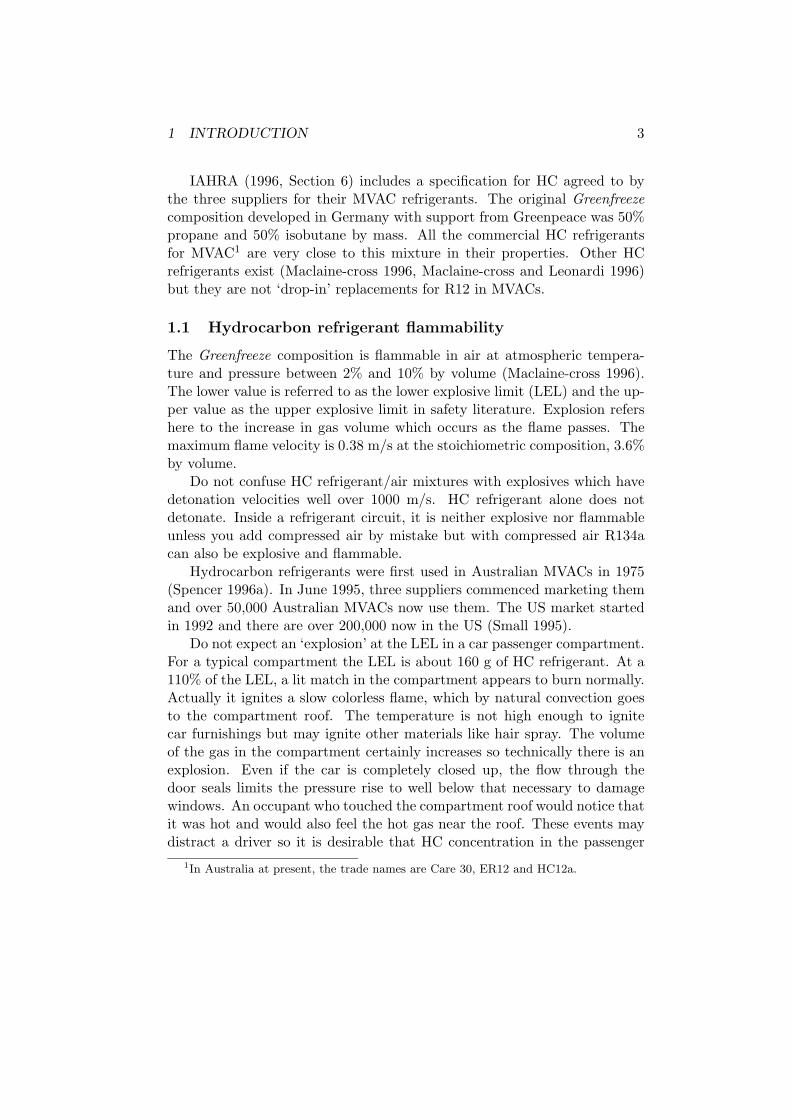
Table 2 gives predicted peak concentrations in the passenger compart-ment for eight release scenarios with ten Australian cars using the data ofTable 1. The concentrations are expressed as a percentage of the lower ex-plosive limit (%LEL). The eight release scenarios are for no safety valve, a

3 REFRIGERANT LEAKS AND SAFETY VALVES 10
simple safety valve and a complex safety valve. The leak types are a sud-den major release, an instantaneous complete fracture and a large leak inthe evaporator. The position of the instantaneous complete fracture in thepassenger compartment is wherever gives the largest concentrations for thesafety valve used. For all scenarios, all the refrigerant charge is assumedto leak through the passenger compartment to atmosphere eventually. Thepeak concentrations differ between scenarios for a given car because the massflow rates of the leaks differ.
When the AC is on there is much liquid in the receiver and some inthe evaporator, condenser and compressor sump as well as the liquid andsuction lines. The AC is expected to be on whenever the outside air exceeds20◦C and the engine is operating. The high side pressure used for flowcalculations was 1200 kPa and the low side pressure 400 kPa with AC on.If the outside air temperature is below 20◦C the condenser being in front ofthe radiator is the coldest point in the system. The bottom of the condenseris also the lowest point so liquid refrigerant gathers there by evaporationand condensation in under an hour after last AC operation. Only refrigerantdissolved in compressor oil remains elsewhere but with a leak this evaporatesso slowly it contributes negligibly to passenger compartment concentrations.The pressure used was 600 kPa with AC off. These are the two most frequentdistributions of refrigerant in MVACs.
BS 4434-1995, Clause 1.3.70, defines a sudden major release as the ma-jority of the refrigerant charge being released in under five minutes. Arefrigerant leak rate which declines linearly with time with half occurring inthe first five minutes satisfies this definition. Leaks through a 1 mm orificein an MVAC suction line approximate this behaviour (Cai 1996). Column3 in Table 2 gives the peak concentrations resulting from this leak pattern.None exceed the LEL. For some applications other than MVAC, BS 4434requires this peak concentration to be less than 20% of the LEL which istrue for all cars after 1980 in Table 2. Safety valves affecting refrigerant floware irrelevant because the refrigerant leakage is defined in BS 4434.
If the expansion valve is in the passenger compartment and there isno safety valve, instantaneous complete fracture in the liquid line can givefrictional, isenthalpic, flashing flow from the receiver to the passenger com-partment (Boucher and Alves 1973, Gallagher et al. 1996). For a liquid linewith 8 mm internal diameter and a total pressure loss coefficient of 4 theinitial flow rate calculated is 250 g/s. If the AC is off, the flow is fromcondenser to passenger compartment and the total loss coefficient used is8. Combined with the lower pressure this reduces the initial flow rate to125 g/s. If the AC is operating, a fracture downstream of the expansion
3 REFRIGERANT LEAKS AND SAFETY VALVES 11
Table 2: Peak average concentration in the passenger compartments of tenAustralian cars as a percentage of the lower explosion limit (LEL) for eightrelease scenarios.
Safety valve None Simple ComplexLeak type Sudden Instantaneous complete fracture LargeInitially AC is BS4434 on off on off on off onModel Year Peak concentration %LELKingswood 1970 92 114 114 114 113 70 69 77Volvo 1978 46 103 103 102 99 28 17 63Commodore 1979 21 121 80 121 80 52 25 80Pulsar 1984 18 85 50 85 50 37 17 50Corolla 1985 7 51 50 44 26 19 9 26Falcon 1987 14 103 59 103 59 46 21 59Laser 1988 12 83 82 72 44 32 15 44Berlina 1989 9 87 48 87 48 39 18 48Magna 1989 9 47 47 44 36 19 9 35Astron 1989 9 64 63 54 30 24 11 30
valve produces the normal refrigerant flow rate since the expansion valve ischoked. If the AC is off and the fracture is downstream of the expansionvalve, only vapour flows at about 20% of the normal refrigerant flow rate.
About half the mass will flash from the preceding initial flows reduc-ing the vapour pressure of the remaining liquid to close to ambient. Themass flow rate is then limited by heat transfer to the liquid to about 10%of the normal operating refrigerant flow rate (Cai 1996, Tosovic 1996). Ta-ble 2 shows the maximum concentrations calculated using the equations inAppendix A for these flows. Figure 2 shows the flow rate and resultingconcentration graphically for the 1984 Pulsar with AC off.
Simple safety valves which close on high flow rate and remain closedwhile the pressure difference is substantial are widely used in LPG systems(AS 1596–1989). An instantaneous complete fracture upstream of the expan-sion valve would cause the safety valve to shut in milliseconds so completefractures are now worse downstream of the expansion valve. Table 2 showsthat simple safety valves have the same effect on maximum concentrationsas moving the expansion valve to the engine bay.
The complex safety valve assessed operates to close:

3 REFRIGERANT LEAKS AND SAFETY VALVES 12
6
-
Leak(g/s)
0
1
2
Concentration(%LEL)
10
20
30
40
50
Time (s)
-100 0 100 200 300 400
qqqqqqqqqqqqqqqqqqqqqqqqqqqqqqqqqqqqqqqqqqqqqqqqqqqqqqqqqqqqqqqqqqqqqqqqqqqqqqqqqqqqqqqqqqqqqqqqqqqqqqqqqqqqqqqqqqqqqqqqqqqqqqqqqqqqqqqqqqqqqqq qqqqqqqqqqqqqqqqqqqqqqqqqqqqqqqqqqqqqqqq qqqqqqqqqqqqqqqqqqqqqqqqqqqqqqqqqqqqqqqqqqqqqq qqqqqqqqqqqqqqqqqqqqqqqqqqqqqqqqqqqq qqqqqqqqqqqqqqqqqqqqqqqqqqqqqqqqqqqqqq qqqqqqqqqqqqqqqqqqqqqqqqqqqqq qqqqqqqqqqqqqqqqqqqqqqqqqqqqqqqqqqqqqqqqqqqqqqqqqqqqqqqqqqqqqqqqqqqqqqqqqqqqqqqqqqqqqqqqqqqqqqqqqqqqqqqq qqqqqqqqqqqqqqqqqqqqqqqqqqqqqqqqqqqqqqqqqq qqqqqqqqqqqqqqqqqqqqqqqqqqqq
Leakqqqqqqqqqqqqqqqqqqqqqqqqqqqqq qqqqqqqqqqqqqqqqqqqqqqqqqqqqq Concentration
Figure 2: Hydrocarbon refrigerant flow rate and concentration as a functionof time for a hypothetical worst leak into the passenger compartment of a1984 Pulsar with air conditioner off.
• 10 s before the compressor clutch disengages to remove liquid fromcomponents with a path to the passenger compartment;
• on a fall in supply electric potential or evaporator pressure;
• or if a very large leak is sensed in the liquid line.
If the AC is on, the worst position for an instantaneous complete fractureis between the expansion valve and the evaporator. The loss in evaporatorpressure is expected to close the valve after only 20% of the charge has leakedto the passenger compartment at the normal flow rate. When the valve isclosed reverse leakage through the compressor valves is at 1% of operatingflow. The worst leak is in the evaporator at 20% of operating flow whichwill not drop the evaporator pressure sufficiently to close the complex valveuntil 50% of the charge has leaked.
If the AC is off with a complex valve, the evaporator has been pumpeddown so only 10% of the charge is available to leak at 20% of operatingflow and the rest at 1% of operating flow through the compressor valves inreverse.

4 FAILURES, FRACTURES AND LEAKS 13
The complex safety valve reduces the maximum concentration of hydro-carbon from a worst hypothetical leak for all cars. Its performance couldbe improved by increasing the fresh air flow rate or by using an HC sensorin the passenger compartment. Proprietary valve systems with significantlybetter performance than the complex valve in Table 2 are under develop-ment. Many of these devices already satisfy the IAHRA (1996), Clause J 2arequirements. Most Australian cars satisfy the Clause J 2 criterion withoutany safety valve. Vehicles with low fresh air like the 1970 Kingswood onlyjust satisfy it with the complex valve.
4 Failures, Fractures and Leaks
Fractures do not just appear. They grow from some initial weakness in ahighly stressed area. Any fracture which penetrates a wall causes a leakor failure of refrigerant containment. If the maximum stresses are small afracture will grow only if the stresses fluctuate and only a fixed microscopicamount per fluctuation. This is called fatigue and is a common failure typein motor vehicles. Typically fatigue fractures take years to grow. Large max-imum stresses causing complete fractures to grow in seconds are extremelyrare except for emergency situations e.g., a collision or a petrol fire.
Six failures claimed to result in exceeding the LEL in the passengercompartment are:
• instantaneous fracture in collision;
• sudden fracture from faults;
• sudden fracture from excessive pressure;
• pitting corrosion of the evaporator;
• fatigue fracture from cyclic stresses;
• failure of O-ring joints.
The IAHRA (1996) clauses preventing these failures causing the LEL tobe exceeded are discussed in the following.
4.1 Instantaneous fracture in collision
The condenser of a car air conditioner system is in front of the radiator.Collisions resulting in fracture of the condenser are common (Arthur D.

4 FAILURES, FRACTURES AND LEAKS 14
Little 1995, Maclaine-cross 1996) and a complete instantaneous escape ofalmost all refrigerant charge to the atmosphere frequently occurs. Withfavourable winds a small fraction of the released refrigerant might enter adamaged passenger compartment but fresh air also entering by the samepath immediately dilutes it preventing a flammable concentration.
Dieckmann et al. (1991) thoroughly investigated wrecks from side im-pacts and found:
A total of 9 right3 A-pillar impacts were tested. CDC4 mag-nitudes of 3 to 5 were estimated for all of these and significantevaporator displacement was observed for several. While signif-icant evaporator displacement occurred, no damage or deforma-tion of the evaporators was observed. No AC system leaks werefound in this population. In addition, window breakage was ob-served in all cases, a point of interest in establishing the potentialfor flammable mixtures and explosive overpressures.
Also the vehicle will be at rest and any sparks from the collision itselfextinguished long before a flammable mass has leaked. The flammable masswill leak out of the passenger compartment in less than a minute if windowsand doors are intact and in seconds when only one window is shattered. For arescuer on an intact scene in less than a minute, opening an undamaged doorautomatically allows any flammable mass to escape in seconds (Razmovski1994, Maclaine-cross 1996) and prevents any explosion. After an impactsevere enough to fracture an evaporator or refrigerant line, the occupantswill certainly be unable to light a match or flint lighter the only knownignition sources (Section 5, Maclaine-cross 1996).
Safety valves (Section 3, Clause J 2) are expected to be particular ef-fective in reducing refrigerant concentrations in the passenger compartmentfor such scenarios.
4.2 Sudden fracture from faults
The design of air conditioners factory installed by US car manufacturersis completely free of features which could cause sudden or instantaneouscomplete fractures in the passenger compartment. This may not be true ofafter-market kits. Over-tightening screw refrigerant fittings and omission of
3US cars are left-hand drive.4Collision Deformation Classification

4 FAILURES, FRACTURES AND LEAKS 15
mounting brackets in the passenger compartment is physically possible withsome kits and may have occurred in the field.
Clauses B, C, D, E, H and I (IAHRA 1996) are intended to prevent faultscausing sudden fracture. Clause J 2 ensures that a flammable mixture inthe passenger compartment does not occur if these fail.
4.3 Sudden fracture from pressure
ASHRAE (1995) states ‘Components for the low-pressure side frequentlyhave burst strengths in excess of 2.1 MPa.’ BS 4434-1995 requires burststrengths up to 5 MPa depending on the pressure relief device. If the ACis off but the engine is operating, liquid refrigerant will gather in the con-denser and its temperature will be the ambient temperature. The maximumambient temperature in Australia is 50◦C and so the maximum pressurethroughout the air conditioner will be 1200 kPa gauge with HC refriger-ant. If the AC is on, condenser and liquid line pressures may be as highas 1600 kPa gauge with HC but the evaporator pressure will then be about300 kPa gauge.
The pressure/temperature relief device mentioned in Clause J 1 is re-quired by refrigeration safety codes (BS 4434-1995). The high pressureswitch in Clause J 1 protects the liquid line which enters the passengercompartment on some systems.
Clause J 2 ensures that a flammable mixture in the passenger compart-ment does not occur if the devices mentioned by Clause J 1 fail.
4.4 Pitting corrosion
Many Australian vehicles are exposed to sea coast atmospheres laden withsalt particles from sea spray. Such particles cause pitting corrosion of thealuminium evaporator with after several years formation of a small pinhole.A 100 µm diameter hole will leak HC vapour at about 10 mg/s causingthe entire charge to leak out in about 10 hours. Such a leak is too smallto cause the LEL to be exceeded (Section 2). Such a leak is failsafe sincethe MVAC will not operate or leak further after the charge has leaked out.IAHRA (1996, Clauses O) requires a vacuum pump leak test with a rise of2 kPa from 10 kPa in 15 minutes ‘indicates a leak is present in the systemand must be rectified prior to final system charging.’ A 100 µm diameterleak would cause a rise of 30 kPa which is certain to be noticed. A newevaporator would be fitted to fix the leak.
4 FAILURES, FRACTURES AND LEAKS 16
4.5 Fatigue fractures
Fatigue fractures can occur because many materials including aluminiumand elastomers have no fatigue limit.
The evaporator components are typically subjected to ten stress cyclesper hour. If a vehicle has an operating life of 20,000 hours this is 200,000cycles of stress. The liquid line is of greatest concern because the same sizecrack leaks liquid at about 15 times the mass flow rate for vapour. TheBS 4434–1995 allowable pressure is 1.7 MPa causing a 9 MPa hoop stress ina 10 mm liquid line. The 500 million cycle fatigue strength for the softesttemper of 5152 aluminium tubing alloy is 90 MPa (ADC 1973). The factorof safety for common fatigue is more than 10 so no such failures are possiblein even soft metal.
With a high stress concentration such as at a scratch, other damage orpoor design feature, crack growth and then refrigerant leakage may occur atlower stresses. Any crack will initially be so small that the leakage could notbe detected under Clause O but the air conditioner will fail to operate aftersome months. As the crack grows the leakage rate increases and Section 2shows that a leakage rate too small to cause the LEL to be exceeded causesall the charge to leak out in hours and would be readily detected underClause O. For any given crack length, theory of elasticity and fluid mechanicscan be used to predict the leakage rate and fracture mechanics whethersudden complete fracture occurs. If a crack length exists which gives aleakage rate below the LEL leakage rate but for which sudden completefailure is impossible, Clause O prevents the LEL being exceeded.
Consider an all aluminium system in the passenger compartment and acrack normal to the principal stress in the liquid line or other liquid contain-ing component 2 mm long. At the 1.7 MPa allowable pressure the crack willopen to 0.5 µm (Timoshenko and Goodier 1951) and leak about 17 mg/s ofliquid. This is smaller than the 28 mg/s required to exceed the LEL withthe lowest closed fresh air flow rate (Section 2). At 17 mg/s the refriger-ant will leak out completely in about 6 hours. Because the crack will closeunder vacuum it may not be detected by the vacuum leak test (IAHRA1996, Clause O) but the pressure test (IAHRA 1996, Clause O) will detectit. A 2 mm crack in aluminium will grow catastrophically if the stress ex-ceeds 1100 MPa (Polakowski and Ripling 1966). This is about 120 timesthe 9 MPa stress occurring at maximum allowable pressure. All aluminiumconstruction is completely safe against exceeding the LEL.
Older MVAC designs still popular on farm and construction equipmenthave refrigerant hoses in the passenger or operator compartment. Refrig-

5 PASSENGER COMPARTMENT IGNITION SOURCES 17
erant hoses have a composite construction. Fatigue fracture of the layerstaking the stress may occur with no loss of refrigerant. A blister developsin the sealing layer which may burst suddenly. Because the stiffness of thislayer is over a hundred times less than aluminium the tear or fracture canopen to over a hundred times the size. This is known to have occurred inan R12 liquid hose with complete sudden loss of refrigerant to the passengercompartment. BS 4434–1995 does not permit refrigerant hoses inside thepassenger compartment. IAHRA (1996, Clause H) requires any hoses whichhave either sustained damage or deteriorated be replaced.
Clause J 2 requires that the consequences of such a failure not be aflammable mixture on average in the passenger compartment. The best wayof ensuring this is to use aluminium refrigerant lines in the passenger com-partment, put the expansion valve in the engine bay, have fresh air greaterthan 100 L/s and avoid excessive refrigerant charges (Table 2). Where suchdesign changes are expensive, various safety valves are available.
4.6 O-ring failure
Most MVACs do not have O-ring joints inside the passenger compartmentand BS 4434–1995 forbids this. The leakage from a missing O-ring or anincorrectly fastened joint will be detected by both the vacuum and pressureleak test at rates much lower than the lowest capable of exceeding the LEL,28 mg/s. O-rings can fail in service due to fatigue but these failures cannotdevelop into a complete fracture like a crack. An O-ring fatigue fracturewould initially cause complete loss of refrigerant in days and it would bereadily detected and replaced on servicing (IAHRA 1996, Clause O). Theseinitial low leakage rates could not cause the LEL to be exceeded.
5 Passenger Compartment Ignition Sources
Ignition sources known to ignite HC refrigerant mixtures at atmosphericconditions and physically possible on a motor vehicle include:
1. Strongly exothermic chemical reactions including ignited matches andbutane cigarette lighters;
2. Heating a flammable mixture of HC above its auto-ignition tempera-ture which has a 490◦C minimum (Maclaine-cross 1996);
3. Hot wires or surfaces above 800◦C (Dieckmann et al. 1991);

5 PASSENGER COMPARTMENT IGNITION SOURCES 18
4. Electric arcs of sufficient energy including spark plugs.
Neither Razmovski (1994) nor Rajasekariah (1995) found ignition sources2, 3 or 4 on the ten cars they tested with an extinguished HC torch eitherinside or outside the passenger compartment (Maclaine-cross 1996). All thecars tested had been well maintained.
If IAHRA (1996) is complied with the LEL will not be exceeded andwhether ignition sources are present is irrelevant. Non-compliance withIAHRA (1996) might well be coincident with poor design, manufacture ormaintenance generally and hence a greater risk of ignition sources. Sourcesin the passenger compartment may cause an overpressure accident (Sec-tion 1.1).
5.1 Hot surfaces
Motor vehicles are wired with negative earth. Positive leads to the passengercompartment have primary fuses in the engine bay to protect the plasticinsulation from damage by conductor heat. Smaller conductors are protectedby secondary fuses inside the passenger compartment. These secondary fusesare designed not to ignite HC/air mixtures on failure.
If a bare positive lead is touched briefly to corroded metal on the carbody, rapid resistive heating takes place at the metal surface with a noisyspatter of hot oxide and metal. This spatter is often called a spark. Underfavorable conditions this spatter could be over the 800◦C required to igniteHC. This effect is believed to have caused fires in engine bays after impacts(Arthur D. Little 1995).
In the passenger compartment, there is little corroded bare metal andleads could only be stripped of their insulation by rare manufacturing faultsor service damage. A short circuit may blow a fuse, discharge the batteryor otherwise attract repair. If not it causes insufficient heating for ignitionor erodes the metal until a short is no longer possible in days. I have neverencountered a short circuit in the passenger compartment capable of ignitionin thirty years of driving. They certainly occur less than once per vehicleyear on average.
Smokers using matches or butane lighters create five ignition events perday for every driver (Maclaine-cross 1996) or over a thousand times the ratefor hot surfaces created by short circuits.

5 PASSENGER COMPARTMENT IGNITION SOURCES 19
5.2 Electric arcs
An electric arc is a volume of ionised gas heated by an electric current. Smallelectric arcs are also called sparks but are a different electrical phenomenato spatter (Section 5.1). They occur on opening a normal circuit not onclosing an abnormal short circuit. If they can occur, they will occur everytime the circuit is opened.
The minimum energy for reliable spark ignition of propane is about250 µJ (Lichty 1967) if the arc length is about 1 mm and the peak elec-tric potential about 20,000 V. SIMTARS (1995) found that the ignitioncharacteristic of HC refrigerants were similar to propane their major con-stituent. Deviation from optimum conditions by using a smaller or largerarc gap produces an increase in the required energy. A smaller gap allowscooling by the electrodes to quench any flame produced.
On spark ignition systems, the energy required is stored in the mag-netic field of the ignition coil. When the primary circuit is interrupted, thismagnetic energy is released as the field collapses. The inductance of thecoil produces the high voltage to arc across the gap. The energy releaseddepends on the size of the coil.
When a non-inductive circuit in the passenger compartment is inter-rupted, the maximum potential available to form an arc is less than 15 V.The first ionization potential of nitrogen is 15.5 electron-volts/molecule andthe breakdown potential for a 25 µm gap in air is about 300 V (Dakin 1968).No arc is possible with non-inductive circuits in the passenger compartment.
The starter motor has a significant magnetic field which collapses whenthe ignition key is released. The starter-motor relay contacts often producevisible arcs. The ignition key however operates the relay coil whose magneticfield has a volume about ten times smaller than the ignition coil. Ten timesless energy is available with an unfavorable gap so the ignition switch archas insufficient energy to ignite an HC/air mixture. The ignition switchis always totally enclosed and armored for security reasons. If the arc didignite HC/air inside the switch the flame would not proceed to the passengercompartment.
Switches inside the passenger compartment operate many small motorswith permanent magnets. Interrupting the rotor current does not changethe magnetic field of rotor or stator much so much less energy is releasedthan from the starter relay coil. The largest such motor is on the blowerbut this is operated through resistors which further reduce the potentialsinduced on switching.
Ignition of HC/air mixtures is impossible by any arcs known to occur in

6 CONCLUSION 20
the passenger compartment under operating or fault conditions.
5.3 Door switches
The courtesy light in passenger compartments is usually 5 W and can be setwith a master switch to operate off up to 4 door switches. The door switchesare in parallel and complete the light circuit by shorting the negative lead tothe car body. Some mount in the car frame but are not otherwise enclosed.
The switch button is usually outside the passenger compartment sealsand the car frame is vented to the atmosphere not the passenger compart-ment. Any ignition source on the switch will not come into contact withHC/air mixture in the passenger compartment, when the switch operatesand hence cannot ignite it.
When the door opens and the switch closes, the lamp series resistancelimits the maximum possible heating of the contacts to 1.3 W. Even if dirtfalls on the contacts or the wire separates from the switch this cannot beincreased. The temperature will be less than 100◦C at any door switch.This is insufficient to ignite HC/air.
For the 1994 Pulsar considered earlier, Razmovski (1994) measured afall of 29.8% in tracer concentration when she opened the driver’s door for3.27 s. Above the 2% LEL, the much larger density difference would makethis loss in passenger compartment concentration even larger.
The maximum current through any door switch is less than 0.5 A becauseof the series resistance of the lamp. The circuit is non-inductive so no arcis possible when the door is closed and the circuit broken.
Door switches are not an ignition source and do not contact any flammablemixture in the passenger compartment when they normally operate.
6 Conclusion
IAHRA (1996) contains many safety and environmental clauses and thoserelevant to exceeding the lower explosion limit of hydrocarbon refrigerantin the passenger compartment are discussed above. These clauses limit thetotal quantity of refrigerant used, then ensure that physically possible leakrates are small and ventilation rates are high. This document summarizesthe engineering reasons why these clauses are effective.
Competent and conscientious compliance with IAHRA (1996) makesoverpressure in the passenger compartment physically impossible from hy-drocarbon MVACs. In the case of noncompliance, the only significant igni-tion sources in the passenger compartment are matches and butane lighters.

7 REFERENCES 21
These clauses in IAHRA (1996) also prevent driver distraction by a cloudof leaking refrigerant or drowsiness due to asphyxiation which are possiblecauses of serious accidents with all refrigerants.
7 References
ADC, 1973, Standards for Australian Aluminium Mill Products, Metric Edi-tion, The Aluminium Development Council of Australia Ltd, Sydney.
AS 1596–1989, LP Gas—Storage and handling, Standards Association ofAustralia, Sydney.
ASHRAE 1995, 1995 ASHRAE Handbook HVAC Applications, Chapter 8,American Society of Heating, Refrigerating and Air Conditioning Engi-neers, Inc., Atlanta.
Arthur D. Little, 1995, Risk Assessment of Flammable Refrigerants, Part 3:Car Air Conditioning, Final Report to Calor Gas Limited by Arthur D.Little Limited, Cambridge, UK, October, 25 p.
Boucher, D. F. and Alves, G. E., 1973, Fluid and Particle Mechanics, Section5 of Chemical Engineers’ Handbook 5th ed., R.H. Perry and C.H. Chiltoneditors, pp. 5-43, 5-44.
BS 4434–1995, Safety and environmental aspects in the design, constructionand installation of refrigerating appliances and systems, British Stan-dards Institution, London, 64 p.
Cai, D., 1996, Escape of Hydrocarbon Refrigerants in Car Air Conditioning,M.Eng.Sc. thesis, School of Mechanical and Manufacturing Engineering,The University of New South Wales, Sydney, 121 p.
Dakin, T. W., 1968, Insulating Gases, Sections 4-306 to 4-315 of StandardHandbook for Electrical Engineers, 10th ed., D. J. Fink and J. M. Carrolleditors, McGraw-Hill, New York.
Dieckmann, J., Bentley, J. and Varone, A., 1991, Non-Inert RefrigerantStudy for Automotive Applications Final Report, Arthur D. Little, Con-tract DTRS-57-89-D00007 US Department of Energy, November, 76 p.
FORS, 1995, Australian Design Rule 15/01, Demisting of Windscreen, Aus-tralian Design Rules for Motor Vehicles and Trailers 3rd ed., FederalOffice of Road Safety, Department of Transport & Communications,Canberra.
Gallagher, J., Huber, M., Morrison, G., and McLinden, M., 1996, NISTThermodynamic Properties of Refrigerants and Refrigerant Mixtures

7 REFERENCES 22
Database (REFPROP), Version 5.0 Users’ Guide, NIST Standard Ref-erence Database 23, U.S. Department of Commerce, National Instituteof Standards and Technology, Gaithersburg MD.
IAHRA, 1996, Code of Practice for the Use of Hydrocarbon Refrigerantsin Motor Vehicle Air Conditioning, Final Draft, The Independent Aus-tralian Hydrocarbon Refrigeration Association, Brisbane, October.
Keebler, J., 1993, Cold fact: A/C gas danger, Automotive News, November,p. 1, 45.
Lichty, L. C., 1967, Combustion Engine Processes, McGraw-Hill, New York,654 p.
Maclaine-cross, I. L., Mills, J., Ramsey, M. et al., 1995, Hydrocarbon Re-frigerants — Supervised Safety Tests at Macs Muffler Mart, 14.5 minutevideo sponsored by Independent Australian Hydrocarbon RefrigerationAssociation and supervised by National Safety Council of Australia Ltd,Brown’s Plains Queensland, 25th November.
Maclaine-cross, I. L., 1996, Insurance Risk for Hydrocarbon Refrigerantsin Car Air-Conditioners, Refrigeration Science and Technology Proceed-ings, International Institute of Refrigeration, Proceedings of meeting ofScientific Commissions E2, E1, B1, B2, Melbourne (Australia), February11–14th, pp. 262–271.
Maclaine-cross, I. L., and Leonardi, E., 1996, Comparative Performance ofHydrocarbon Refrigerants, Refrigeration Science and Technology Pro-ceedings, International Institute of Refrigeration, Proceedings of meet-ing of Scientific Commissions E2, E1, B1, B2, Melbourne (Australia),February 11–14th, pp. 238–245.
Polakowski, N. H. and Ripling, E. J., 1966, Strength and Structure of En-gineering Materials, Prentice-Hall, Englewood Cliffs.
Rajasekariah, C., 1995, Hydrocarbon Refrigerant Safety in Automobiles,B.E. thesis, School of Mechanical and Manufacturing Engineering, TheUniversity of New South Wales, Sydney, 140 p.
Razmovski, V., 1994, Safety of Hydrocarbon Refrigerants for Car Air Con-ditioning Systems, B.E. thesis, School of Mechanical and ManufacturingEngineering, The University of New South Wales, Sydney, 97 p.
SAE 1995, Safety and Containment of Refrigerant for Mechanical VaporCompression Systems used for Mobile Air-Conditioning Systems –SAEJ639 APR94, SAE Recommended Practice, SAE Handbook Volume 3,Society of Automotive Engineers, Inc., Warrendale PA, pp. 34.40–34.42.

A PREDICTING COMPARTMENT CONCENTRATIONS 23
SIMTARS, 1995, Comparison of Ignition Energy and Auto-Ignition Temper-atures between Propane and Two Refrigerants, Report No: E95/0581,Safety in Mines Testing and Research Station, Redbank QLD, 4 p.
Small, R., 1995, Letter to Ian Maclaine-cross, OZ Technology Inc., Idaho,17th November, 1 p.
Spencer, C., 1996a, oral communication to author, Esanty Pty Ltd, Victoria,15th February.
Spencer, C., 1996b, oral communication to author, Esanty Pty Ltd, Victoria,11th October.
Timoshenko, S. and Goodier, J. N., 1951, Theory of Elasticity, 2nd edition,McGraw-Hill, New York.
Tosovic, D. R., 1996, Hydrocarbon Refrigerant Safety in Automobiles, M.Eng.Sc. thesis, School of Mechanical and Manufacturing Engineering,The University of New South Wales, Sydney, 200 p.
Yan, W., Overpressure in Car Passenger Compartments, M.Eng.Sc. thesis,School of Mechanical and Manufacturing Engineering, The University ofNew South Wales, Sydney, 98 p.
A Predicting Concentrations ina Passenger Compartment
Leaks into a passenger compartment can frequently be divided into twoconstant flow rate regimes as shown in Figure 2 (page 12). The followingformulae give the spatial average concentration in the passenger compart-ment. Forced and natural convection ensure that except very close to theleak, the local concentration is equal to this average especially a minute afterthe leak commenced.
If mi is the mass leaking at rate mi during period ti, then ti = mi/mi. Ifvl is the specific volume of the leaking gas at the temperature and pressureof the compartment, the volume flow rate of the leak Vi = vlmi. For hydro-carbon refrigerants replacing R12 vl = 0.5 L/g. The passenger compartmenthas a volume V and its fresh air volume flow rate is Vf .
The volume concentration c1 at time t1 after the leak commenced is
c1 =V1
Vf + V1
(1− e−
Vf+V1V
t1
)

A PREDICTING COMPARTMENT CONCENTRATIONS 24
At time t1 + t2 after all gas has leaked the volume concentration c2 is
c2 =V2
Vf + V2
+
(c1 −
V2
Vf + V2
)e−
Vf+V2V
t2
After time t1 + t2 and at a time t after the initial leak, the volumeconcentration c decays following
c = c2e−VfV
(t−t1−t2)
The maximum volume concentration of gas is the greater of c1 or c2.