hydrodynamic fin function of brief squid, lolliguncula...
TRANSCRIPT

2009
INTRODUCTIONSquid employ a complex locomotive approach involving twoseparate systems, the pulsed jet and movement of the lateral fins(Bartol et al., 2001b). However, many studies involving squidswimming performance have focused primarily on the jet whilelargely ignoring fin contributions to propulsion (Johnson et al., 1972;Anderson and DeMont, 2000; Anderson and Grosenbaugh, 2005;O’Dor, 1988), with other studies assuming the fins function onlyin stability and steering (O’Dor and Webber, 1991; Webber andO’Dor, 1986). As suggested by O’Dor (O’Dor, 1988), Hoar et al.(Hoar et al., 1994), Bartol et al. (Bartol et al., 2001b; Bartol et al.,2008) and Anderson and DeMont (Anderson and DeMont, 2005),the fins of squid may play important roles in lift and thrustproduction at various speeds. In fact, based on force balancepredictions by Bartol et al. (Bartol et al., 2001b), the fins of shallow-water squids may produce more lift and thrust forces than the jetat certain speeds.
Both the morphometric form and function of fins vary acrosssquid species (Hoar et al., 1994). Pelagic, fast movingommastrephid squid have stout, triangular fins that flap during lowspeed cruising and extend outward at higher speeds, presumablyto act as rudders (O’Dor and Webber, 1991; Webber and O’Dor,1986). The small shape of the fins is important for drag reductionat higher swimming speeds but does not lend itself well to low-speed undulatory swimming. By contrast, the larger fins of coastalsquid are used not only for maneuvering and stability, but also thrust
production at low to moderate speeds (Anderson and Demont, 2005;Bartol et al., 2001b). Partly because of the increased drag actingon these larger fins, inshore myopsid squid often wrap the finstightly around the mantle at high speeds (O’Dor, 1982; O’Dor,1988). The absence of fin motion at these higher speeds is probablya product of support limitations of the fin’s muscular hydrostat(Kier, 1989). Deep sea squids living at meso- and bathypelagicdepths rely even more heavily on fin locomotion than shallow waterspecies. Many deep-sea squid species have large fins that slowlyundulate or flap to achieve relatively low swimming velocities, evenduring escape responses. These large fins presumably areresponsible for the majority of locomotive forces, with the jetplaying a reduced role (Vecchione et al., 2001; Vecchione et al.,2002).
Despite intriguing differences in fin form and function, very littleis known about the locomotive role of fins in any squid. O’Dor(O’Dor, 1988), Hoar et al. (Hoar et al., 1994), Bartol et al. (Bartolet al., 2001b) and Anderson and DeMont (Anderson and DeMont,2005) have all collected kinematic data that provide a valuable recordof fin movements in various squid species (e.g. fin wave speed, finamplitude, fin wave shape), and Bartol et al. (Bartol et al., 2001b),O’Dor (O’Dor, 1988) and Anderson and DeMont (Anderson andDeMont, 2005) made fin force predictions based largely onkinematic data. However, little qualitative or quantitative data offlows around the fins that can be used to understand force productionhave been collected to date.
The Journal of Experimental Biology 213, 2009-2024© 2010. Published by The Company of Biologists Ltddoi:10.1242/jeb.039057
Hydrodynamic fin function of brief squid, Lolliguncula brevis
William J. Stewart1,*, Ian K. Bartol2 and Paul S. Krueger3
1University of California-Irvine, Irvine, CA 92697, USA, 2Old Dominion University, Norfolk, VA 23529, USA and 3Southern MethodistUniversity, Dallas, TX 75275, USA
*Author for correspondence ([email protected])
Accepted 4 March 2010
SUMMARYAlthough the pulsed jet is often considered the foundation of a squid’s locomotive system, the lateral fins also probably play animportant role in swimming, potentially providing thrust, lift and dynamic stability as needed. Fin morphology and movement varygreatly among squid species, but the locomotive role of the fins is not well understood. To begin to elucidate the locomotive roleof the fins in squids, fin hydrodynamics were studied in the brief squid Lolliguncula brevis, a species that exhibits a wide rangeof fin movements depending on swimming speed. Individual squid were trained to swim in both the arms-first and tail-firstorientations against currents in a water tunnel seeded with light-reflective particles. Particle-laden water around the fins wasilluminated with lasers and videotaped so that flow dynamics around the fins could be analyzed using digital particle imagevelocimetry (DPIV). Time-averaged forces generated by the fin were quantified from vorticity fields of the fin wake. During the lowswimming speeds considered in this study [<2.5 dorsal mantle lengths (DML) per second], L. brevis exhibited four unique fin wakepatterns, each with distinctive vortical structures: (1) fin mode I, in which one vortex is shed with each downstroke, generallyoccurring at low speeds; (2) fin mode II, an undulatory mode in which a continuous linked chain of vortices is produced; (3) finmode III, in which one vortex is shed with each downstroke and upstroke, and; (4) fin mode IV, in which a discontinuous chain oflinked double vortex structures is produced. All modes were detected during tail-first swimming but only fin modes II and III wereobserved during arms-first swimming. The fins produced horizontal and vertical forces of varying degrees depending on strokephase, swimming speed, and swimming orientation. During tail-first swimming, the fins functioned primarily as stabilizers at lowspeeds before shifting to propulsors as speed increased, all while generating net lift. During arms-first swimming, the finsprimarily provided lift with thrust production playing a reduced role. These results demonstrate the lateral fins are an integralcomponent of the complex locomotive system of L. brevis, producing lift and thrust forces through different locomotive modes.
Key words: digital particle image velocimetry, fin, lift, locomotion, squid, thrust.
THE JOURNAL OF EXPERIMENTAL BIOLOGY

2010
A swimming or flying organism generates locomotive forces bytransferring momentum into the fluid wake, which is oftencharacterized by discrete vortices. The momentum associated withthese vortices thus can be used to estimate locomotive forces (Penget al., 2007). The technique of digital particle image velocimetry(DPIV) (Willert and Gharib, 1991) allows for the flow quantificationand visualization of vortices around a swimming organism, and hasbeen used in several studies to estimate the pectoral fin forcecontributions of fish (Drucker and Lauder, 1999; Drucker and Lauder,2001; Drucker and Lauder, 2003). For this study, DPIV was used tomeasure flows and estimate force production associated with the finsof Lolliguncula brevis, to better understand locomotive fin function.
Brief squid, Lolliguncula brevis, are shallow water, coastalorganisms with relatively large, rounded lateral fins. Theseeuryhaline squid are highly maneuverable (Bartol et al., 2002) andpresumably rely heavily on fins for locomotion (Hoar et al., 1994).Bartol et al. (Bartol et al., 2001b) extensively studied L. breviskinematics and predicted that the fins actively produce lift and thrust,especially at low swimming speeds. Furthermore, L. brevis exhibitsa range of fin movements, from undulations at low speeds totransitional undulatory flapping at intermediate speeds to moredefined flapping at higher speeds (Bartol et al., 2001b). This heavyreliance on fin motion coupled with the versatility of fin movementsafforded by the muscular hydrostatic system make L. brevis anexcellent subject to study squid fin locomotion.
This study had three specific objectives: (1) to determine if thefins generate significant locomotive forces, (2) to describe any wakepatterns produced by the fins, and (3) to document how lift andthrust production by the fins change with speed. Although squidemploy a complex dual mode locomotive system involving bothfins and a pulsed jet and this study focuses on only one componentof this system, it provides the first quantitative data on fin flowsaround squids, which will help us better understand the completelocomotive strategy of squid. Fin function was investigated duringboth arms-first and tail-first swimming because squid swim in twodifferent orientations. Although Lolliguncula does not have apronounced anatomical tail like other squids, we use ‘tail-firstswimming’ for convenience to describe a mode of swimming wherethe posterior portion of the mantle is at the leading edge.
MATERIALS AND METHODSAnimal maintenance
Adult specimens of Lolliguncula brevis Blainville (3.5–9cm dorsalmantle length; DML) were captured by otter trawl within
embayments near Wachapreague on the Eastern Shore of Virginia,USA. Trawls were conducted during August, September andOctober because L. brevis catch probabilities are highest within theChesapeake Bay during this time (Bartol et al., 2002). Captured L.brevis were quickly and carefully transferred first to a bucket forink release before being placed in a 114liter, circular holding tank(Angler livewells, Aquatic Eco-Systems, Inc., Apopka, FL, USA)fitted with two portable battery-powered aerators (Model B-3,Marine Metal Products Co., Inc., Clearwater, FL, USA) for transportto the lab. A maximum of 12 individuals were kept in a singlelivewell to avoid stress from overcrowding.
In the lab, all individuals were housed in a 3-tank, 600literartificial seawater system filled with water maintained attemperatures and salinities equal to those of the capture sites(19–22°C; 30–35‰, respectively). The tanks were circular withmoderate current flow to reduce wall abrasions and promote activeswimming, as suggested by Hanlon et al. (Hanlon et al., 1983). Squidwere fed a plentiful diet of live Palaemonetes pugio and Fundulusspp. and allowed to acclimatize for at least 24h beforeexperimentation. Given that the seawater system consists of threeseparate tanks, smaller individuals were kept separate from largerindividuals to minimize intraspecific aggression. In total, 14 squidranging from 3.5 to 6.2cm DML were selected for this study.
HydrodynamicsA 250liter flume (Model 502{S}, Engineering Laboratory Design,Inc., Lake City, MN, USA) with a 15cm�15cm�43cm workingsection was used for experimentation (Fig.1). The flume was filledwith aerated, artificial seawater of similar salinity and temperatureto that present in the holding tanks. Only one squid was placed inthe flume at a time for experimentation. Squid initially acclimatedto the flume at speeds of 2–4cms–1 with low ambient light tominimize stress. After approximately 15–30min of acclimation,when steady swimming was observed at the initial flume speed,hydrodynamic data were collected for several minutes dependingon the squid’s behavior. The flow velocity of the flume was thenslowly increased using 1cms–1 intervals, followed by anotheriteration of data collection once 5min of steady swimming wasobserved. This procedure of flume speed elevation, acclimation anddata collection was repeated until the squid could no longer keeppace with the flow. After experimentation, squid were over-anesthetized using a 10% solution of MgCl2 (Messenger et al., 1985).Before preservation in formalin, the DML and mass of each squidwere recorded. Fin area was calculated from digital images of
W. J. Stewart, I. K. Bartol and P. S. Krueger
Flow
Laser head
Flume
4 axis traverse
Laser sheet Lateralcamera
Ventralcamera
Laser arm
DPIVcamera
x y
Fig.1. Schematic representation of the experimental setup,illustrating the flume, laser, cameras, and 4-axis traverse.
THE JOURNAL OF EXPERIMENTAL BIOLOGY

2011Hydrodynamic fin function of brief squid
preserved specimens using ImageJ image processing and analysissoftware (freeware: http://rsb.info.nih.gov/ij/).
A DPIV system was used to collect hydrodynamic data aroundone of the squid’s lateral fins [i.e. the fin closest to the DPIVcamera (see Fig.1)] as it swam at the various flume speeds.Neutrally buoyant, silver-coated, hollow glass spheres (meandiameter14m; Potters Industries, Inc., Malvern, PA, USA) wereadded to the flume for use as light-reflective particles. Two pulsedNd:YAG lasers (wavelength532nm, power rating 350mJ perpulse; LaBest Optronics Co. Ltd, Beijing, China), with an attachedoptical arm produced particle-illuminating light sheets,approximately 1mm thick, from underneath the working sectionin the parasagittal (x–y) plane. The duration of each laser pulsewas 7ns and the time interval (t) between laser A and laser Bfiring was 1–4ms. Each laser operated at 15Hz, creating 15 laserpulse pairs per second. A CCD ‘double shot’ video camera (UP-1830CL, UNIQ Vision, Santa Clara, CA, USA) with a frame sizeof 1024�1024pixels and a frame rate of 30Hz was positionedto the side of the flume, perpendicular to the laser sheet, and wassynchronized with the laser pulses to capture images of theilluminated particles. A CMOS video camera (Model 1M150-SA,DALSA, Waterloo, Ontario, Canada) was positioned underneaththe working section to capture images from the ventralperspective. This camera was synchronized with the CCD cameraand provided high resolution images (1024�1024pixels) of thelaser sheet position on the squid’s body. A second, identicalCMOS video camera (also synchronized with the CCD camera)was positioned directly beside the CCD video camera to providean expanded lateral field of view of the mantle and fins (Fig.1).
Synchronization of the cameras and laser pulses was achievedusing an in-house timing program and PCI-6602 counter/timing card(National Instruments, Inc., Austin, TX, USA), which delivered a5.0V TTL triggering signal to the three video cameras and a pulsegenerator (Model 565, Berkeley Nucleonics Corp., San Rafael, CA,USA). The pulse generator locked onto the TTL signal andcontrolled the firing of the two lasers. Each video camera sent imagesto a separate CL-160 capture card (IO industries, Inc., London,Ontario, Canada), each of which provided direct data transfer tohard disk.
All cameras and the optical laser arm were mounted on a four-axis traverse system (Techno-Isel, New Hyde Park, NY, USA;Fig.1). Using a joystick, a PCI-7344 motion controller board(National Instruments Inc., Austin, TX, USA), and a LabVIEW VIcustom program (National Instruments, Inc., Austin, TX, USA), thethree cameras and laser arm were moved simultaneously along thetraverse to follow the target squid to different areas of the watertunnel. To avoid inaccurate flow measurements, data were onlycollected when the cameras and laser arm were not in motion. Thetraverse system was important because it allowed the laser sheet tobe moved to desirable fin locations on the actively swimming squid.
DPIV data sequences ranging in length from approximately 10to 200 image pairs were collected for all squid at various speeds.Only sequences in which the squid exhibited steady swimming whilemaintaining a relatively constant vertical position in the workingsection were considered for analysis. For those sequences wherethe squid did not perfectly match the free stream flow (tunnel speed),swimming velocity was calculated according to net horizontaldisplacement during each jet pulse. The laser sheets were positionedclose to the terminal end of the squid’s lateral fin as it translatedthrough a stroke (Fig.2). In total, 24 speeds of tail-first swimmingand 14 speeds of arms-first swimming were used in thehydrodynamic analysis (each speed consisted of one to four image
sequences; each image sequence consisted of two to five sequentialfin stroke cycles).
For analysis of the DPIV data, each image was divided into a matrixof 32�32pixel interrogation windows with a 16 pixel offset (50%overlap) for cross-correlation analysis which yielded a 66�66 matrixof vectors. The remaining procedure for DPIV image analysis usedin the present study was identical to that described in other studies(see Bartol et al., 2008; Bartol et al., 2009a; Bartol et al., 2009b), andthus we refer the reader to these studies for detailed descriptions ofthe protocols. As in previous locomotive studies involving fish (e.g.Drucker and Lauder, 1999; Müller et al., 1997; Müller et al., 2000;Tytell, 2004), time-averaged forces produced by the fin were estimatedusing DPIV data. Matlab utilities developed in-house were used tocalculate hydrodynamic impulse and kinetic energy of vortices shedinto the fin wake. Axisymmetry about the midline of shed vortexpairs was assumed in all calculations (i.e. vortex pairs were assumedto be circular vortex rings).
When vortices shed from sequential fin strokes were sufficientlyspaced to consider the vortices ‘isolated’ (vortex spacing>two vortexdiameters), hydrodynamic quantities were determined for each wakevortex (i.e. vortex ring) as follows. First, the location of the angledcenterline of the vortex ring was determined based on the best fitof the velocity and vorticity data for the central jet of the vortexring. The angle of the centerline (orientation of the central jet), wasused to determine the vortex ring angle (Fig.3A). Vortex ring angleswere assigned values from 0 to ±180deg depending on orientationrelative to free-stream flow, with negative and positive values beingassigned to angles above and below the free-stream axis,respectively. Second, using the angled centerline as the r0 axis,jet impulse (magnitude) and kinetic energy were computed usingthe equations:
where I is magnitude of the hydrodynamic impulse, wq is theazimuthal component of vorticity, r is the radial coordinate relativeto the jet centerline, E is kinetic energy, y is the Stokes streamfunction, and r is fluid density. The area integrals were computedusing a two-dimensional (2-D) version of the trapezoidal rule.
Time-averaged force contributions were determined separatelyfor fin upstrokes and downstrokes at a particular swimming speed
I / ρ = π ωθ r2 drdxvortex∫ (1)
E / ρ = π ωθ ψ drdxvortex∫ (2),
y
Flow
x
Fig.2. Schematic diagram illustrating the laser sheet (wavelength532nm,thickness1–2mm), oriented vertically in the x–y plane, projecting througha squid’s lateral fin while swimming in the tail-first orientation.
THE JOURNAL OF EXPERIMENTAL BIOLOGY
2012
using the results of Eqn1. First, the impulse of a single downstrokewas measured by calculating the average impulse of a shed vortexover two to four sequential frames. The impulse values of two tofive sequential downstrokes were then averaged to determine theentire sequence’s mean downstroke impulse. To calculate the time-averaged downstroke force, FD, for a particular swimming sequence,the mean downstroke impulse of the sequence was divided by theaverage downstroke period. This time-averaged force, FD, was thengeometrically separated into horizontal thrust, FT,D, and vertical lift,FL,D, based on the mean vortex ring angle (Fig.3A). For simplicity,the use of the term ‘lift’ in this study refers to vertically orientedforces in the x–y plane, which should be a good approximation tothe actual lift force as the free-stream flow in the water tunnel washorizontal and only sequences where the squid held vertical andhorizontal station well were included in the study. This forcecalculation procedure was repeated for all upstrokes for eachsequence. To account for any intraspecific variations in forceproduction among squid of different body sizes, time-averagedforces were normalized according to fin area and expressed asmNcm–2. All swimming speeds were normalized according tomantle length and expressed as DMLs–1.
The time-averaged thrust, FT, and lift, FL, of a complete fin cycle(upstroke and downstroke) were calculated with the followingequations:
where IxU is the horizontal component of the mean impulse producedby the upstroke, IxD is the horizontal component of the mean impulseproduced by the downstroke, tU is the upstroke period, tD is thedownstroke period, and IyU and IyD are the vertical components ofthe mean impulse produced by the upstroke and downstroke,respectively. The magnitude and angular orientation of the time-averaged force produced by the complete fin cycle, F, wasgeometrically calculated from thrust, FT, and lift, FL.
FT =IxU + IxD
tU + tD
(3)
FL =IyU + IyD
tU + tD
(4),
In many cases, vortices shed from sequential strokes were closelyspaced or joined/merged. This prevented separate force estimatesfor upstrokes and downstrokes because of the potential interactionsamong neighboring vortices. For cases where groups of vorticeswere close together (within 1 ring diameter from one another) butwidely separated from other vortices and boundaries (mode IV,Fig.6F,G), the vortices were treated as a group with relevanthydrodynamic quantities computed as follows. Beginning with thegeneral equation for hydrodynamic impulse, the impulse associatedwith a region of vorticity can be computed from:
where w is the vorticity vector, x is the position vector, and I is theimpulse vector (Saffman, 1992). For the case where the vortices areaxisymmetric vortex rings that do not intersect, Eqn5 reduces to:
where the sum is over all vortices, i, in the group, âi is a unit vectoraligned with the axis of vortex i, and ri is the radial distance fromthe axis of vortex i. That is, Eqn1 can still be used to compute thecontribution of individual vortices to the total impulse of the groupof vortices as long as their orientation is properly accounted for andthe results are combined vectorially to obtain the total hydrodynamicimpulse I. Using this observation, the axis of each vortex in thegroup was identified as the line midway between the vorticity peaksassociated with each vortex ring in the group and orthogonal to theline connecting the peaks. Then the impulse associated with eachvortex ring was computed using Eqn1 and combined vectorially(assuming the vortex centers are in the same plane) to obtain thetotal hydrodynamic impulse (total for the combined upstroke anddownstroke) as in Eqn6. Using this result, the impulse magnitude,I|I|, and horizontal and vertical components, Ix and Iy, weredetermined geometrically. Impulse values were converted to time-averaged forces by averaging the Ix and Iy values over two to sixsequential fin cycles and dividing by the average fin beat periodduring these cycles.
I
ρ=
1
2x × dV∫ (5),�
I
ρ= π ai ωθ ri
2 drdxi∫
i
∑ (6),
W. J. Stewart, I. K. Bartol and P. S. Krueger
0 deg–β
+90 deg
–90 deg
±180deg
Vortexring pair
Centraljet
10
B
Velocity (cm s–1) Vorticity (cm s–1)
50
1 cm
C
z
A
rr
z
β
Vortexring pair
Centraljet
0 +40–40
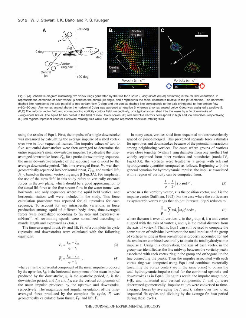
Fig.3. (A)Schematic diagram illustrating two vortex rings generated by the fins for a squid (Lolliguncula brevis) swimming in the tail-first orientation. zrepresents the centerline of each vortex, denotes the central jet angle, and r represents the radial coordinate relative to the jet centerline. The horizontaldashed line represents the axis parallel to free-stream flow (0deg) and the vertical dashed line corresponds to the axis orthogonal to free-stream flow(–90/+90deg). Any vortex angled above the horizontal 0deg was assigned a negative whereas a vortex angled below 0deg was assigned a positive .(B,C)The velocity vector field and corresponding vorticity contour field, respectively, of a typical vortex shed into the wake by a fin downstroke ofLolliguncula brevis. The squid fin lies dorsal to the field of view. Color scales: (B) red and blue vectors correspond to high and low velocities, respectively;(C) red regions represent counter-clockwise rotating fluid while blue regions represent clockwise rotating fluid.
THE JOURNAL OF EXPERIMENTAL BIOLOGY

2013Hydrodynamic fin function of brief squid
For cases where vortices were shed in a nearly continuous,closely-packed train (mode II, Fig.6C; Fig. 7A,B), the vorticeswere too close together to be considered ‘isolated’ and could notbe segregated into groups. In this case, the interaction of thevortices was handled explicitly. To approximate the vortexinteraction effect, the impulse associated with the lead vortex ringin the train was computed as:
where â is a unit vector aligned with the axis of the lead vortex,ue,i is the velocity field induced on the lead vortex by trailing vortexi, ti is the formation time of trailing vortex i (tU or tD asappropriate), and both spatial integrals are taken over the extent ofthe lead vortex (Saffman, 1992). For purposes of approximating theinteraction integral (last term in Eqn7), ue,i was computed from theBiot-Savart induction law assuming the vorticity field of vortex iwas axisymmetric about its own axis.
To use Eqn7, the axis of each vortex involved in the calculationwas determined in the same manner as the calculation involvingEqn6. Then the interaction velocity ue,i was determined for aspecified number of vortices following the lead vortex in the trainand the interaction integral is computed by integrating ue,i�w overthe lead vortex under the assumption that the lead vortex vorticityfield was axisymmetric about its own axis. Unless otherwisespecified, only one vortex following the lead vortex was used inthe computation as the influence of more remote vortices on thelead vortex was minimal. Then, the terms in Eqn7 were combinedvectorially to find I, where the impulse magnitude, I|I|, andhorizontal and vertical components, Ix and Iy, were determinedgeometrically. Finally, to convert impulse values to time-averagedforces, the impulse I for leading vortices from two to six sequentialfin cycles was computed from Eqn7 and then the average Ix and Iy
values were divided by the average fin beat period during thesecycles.
Regardless of whether Eqns6 or 7 was used to determine I andtime-averaged forces for closely spaced vortices, the kinetic energyassociated with the vortices in these situations was determined using:
where y is the Stokes stream function. Eqn8 assumes axisymmetryabout the axis of the vortex ring. The stream function y wasdetermined from the DPIV velocity field assuming axisymmetryabout the axis of the vortex of interest. This assumption may notbe valid – even if the vorticity field is axisymmetric – because ofthe influence of neighboring vortices. To reduce error in thecalculation of y due to the effect of asymmetry in the velocity field,the integral in Eqn8 was computed for both vortex cores (bothpositive and negative wq) in each vortex ring and the results averagedtogether to determine the kinetic energy associated with a givenvortex ring. The kinetic energy for an entire fin cycle is then obtainedby summing the kinetic energy for the upstroke and downstrokevortices.
It should be noted that the current approach probably estimatesthe lower limits of fin force production. Because force was estimatedfrom 2-D x–y cross sections of 3-D vorticity in the fin wake, lateralforce components in the x–z plane were not included. Additionally,
I
ρ= π a ωθ r2 drdx∫ − ue , i × dVdt∫
ti
∫i
∑
≈ π a ωθ r2 drdx∫ − Δti ue , i × dV∫i
∑ , (7)
�
�
E
ρ= π ωθψ drdx
vortex∫ , (8)
out-of-plane stretching or contraction of the vortices could not becaptured.
Using the results for time-averaged thrust (determined fromimpulse using Eqns1, 6 or 7 as appropriate) and vortex kinetic energy(from Eqn2 or 8 as appropriate), fin propulsive efficiency wascalculated for the various swimming speeds using the equation:
where hP(fins) is the propulsive efficiency of the fins, FT is the time-averaged fin thrust, U is the mean swimming speed, and E
–f is the
time-averaged rate at which excess kinetic energy is shed by thefins, i.e. the peak excess kinetic energy measurement divided bythe fin cycle period. Fin efficiencies were subsequently comparedamong fin modes. For swimming speeds where the fins producednet drag (negative thrust) over the fin cycle, an efficiency value of0 was assigned.
RESULTSFin wake patterns
Hydrodynamic fin data from ten Lolliguncula brevis(3.7–6.2cmDML) swimming tail-first at speeds from 0.19 to1.89DMLs–1 and eight L. brevis (3.5–5.3cmDML) swimmingarms-first at speeds from 0.61 to 2.33DMLs–1 were analyzed.Vortices were present in some portion of the fin wake during allspeeds for both orientations (Fig.3B,C). As the fin began translatingthrough a stroke, two regions of counter-rotating fluid developednear the leading and trailing edges of the fin, representing theupstream and downstream components of a single vortex,respectively. These regions of vorticity grew in strength through fintranslation until stroke reversal, at which time the vortex was shedinto the wake. Although ‘leading-edge’ and ‘trailing-edge’ arecommonly used modifiers to describe the separate regions ofvorticity shed from a fin, in the present study the orientation of thesquid with respect to the flow may change (arms-first vs. tail-firstswimming), so we choose to use the more general terms ‘upstreamvortex’ and ‘downstream vortex’ to refer to leading-edge andtrailing-edge vortices, respectively (Fig.4). Typically the formationof the upstream and downstream vortices was synchronized, butduring a few fin strokes the precise timing of vortex formation andsubsequent shedding was not completely in phase.
Although vortices shed from a fin were consistently detected, finwake signatures changed dramatically with swimming speed interms of circulation strength, vortex size, vortex ring angle andinteraction between separate vortex pairs. Each stroke(upstroke/downstroke) of a full fin beat cycle also exhibited differentwake dynamics. All downstrokes produced vortices across the entireswimming speed range for both orientations, but some fin upstrokeswere passive, i.e. no detectable vortices were shed, although mostupstrokes did have associated vortices.
Four qualitatively distinct hydrodynamic fin wake patterns,referred to as swimming fin modes, were observed. Fin wakefeatures such as vortex spacing, the presence/absence of vorticesgenerated by fin strokes (upstrokes versus downstrokes), and thetemporal pattern of vortex generation were used to qualitativelydistinguish the different fin swimming modes. A schematic diagramof these modes is depicted in Fig.5. In fin mode I (Fig.6A,B), asingle vortex was shed from the fin downstroke but the upstrokedid not shed detectable vorticity into the wake. In fin mode II,denoted IIT for tail-first swimming (Fig.6C) and IIA for arms-firstswimming (Fig.7A,B), a chain of seemingly linked vortices wasproduced by an undulating fin. In fin mode III, denoted IIIT for tail-
ηP (fins) =FTU
FTU + �E f
, (9)
THE JOURNAL OF EXPERIMENTAL BIOLOGY
2014
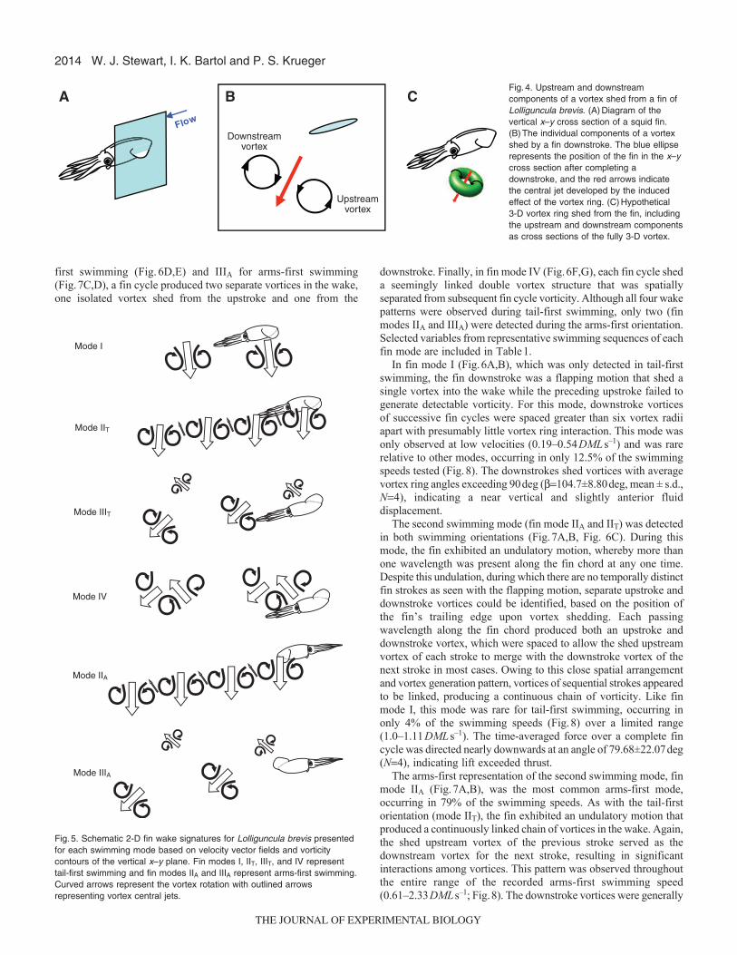
first swimming (Fig.6D,E) and IIIA for arms-first swimming(Fig.7C,D), a fin cycle produced two separate vortices in the wake,one isolated vortex shed from the upstroke and one from the
downstroke. Finally, in fin mode IV (Fig.6F,G), each fin cycle sheda seemingly linked double vortex structure that was spatiallyseparated from subsequent fin cycle vorticity. Although all four wakepatterns were observed during tail-first swimming, only two (finmodes IIA and IIIA) were detected during the arms-first orientation.Selected variables from representative swimming sequences of eachfin mode are included in Table1.
In fin mode I (Fig.6A,B), which was only detected in tail-firstswimming, the fin downstroke was a flapping motion that shed asingle vortex into the wake while the preceding upstroke failed togenerate detectable vorticity. For this mode, downstroke vorticesof successive fin cycles were spaced greater than six vortex radiiapart with presumably little vortex ring interaction. This mode wasonly observed at low velocities (0.19–0.54DMLs–1) and was rarerelative to other modes, occurring in only 12.5% of the swimmingspeeds tested (Fig.8). The downstrokes shed vortices with averagevortex ring angles exceeding 90deg (104.7±8.80deg, mean ± s.d.,N4), indicating a near vertical and slightly anterior fluiddisplacement.
The second swimming mode (fin mode IIA and IIT) was detectedin both swimming orientations (Fig.7A,B, Fig. 6C). During thismode, the fin exhibited an undulatory motion, whereby more thanone wavelength was present along the fin chord at any one time.Despite this undulation, during which there are no temporally distinctfin strokes as seen with the flapping motion, separate upstroke anddownstroke vortices could be identified, based on the position ofthe fin’s trailing edge upon vortex shedding. Each passingwavelength along the fin chord produced both an upstroke anddownstroke vortex, which were spaced to allow the shed upstreamvortex of each stroke to merge with the downstroke vortex of thenext stroke in most cases. Owing to this close spatial arrangementand vortex generation pattern, vortices of sequential strokes appearedto be linked, producing a continuous chain of vorticity. Like finmode I, this mode was rare for tail-first swimming, occurring inonly 4% of the swimming speeds (Fig.8) over a limited range(1.0–1.11DMLs–1). The time-averaged force over a complete fincycle was directed nearly downwards at an angle of 79.68±22.07deg(N4), indicating lift exceeded thrust.
The arms-first representation of the second swimming mode, finmode IIA (Fig.7A,B), was the most common arms-first mode,occurring in 79% of the swimming speeds. As with the tail-firstorientation (mode IIT), the fin exhibited an undulatory motion thatproduced a continuously linked chain of vortices in the wake. Again,the shed upstream vortex of the previous stroke served as thedownstream vortex for the next stroke, resulting in significantinteractions among vortices. This pattern was observed throughoutthe entire range of the recorded arms-first swimming speed(0.61–2.33DMLs–1; Fig.8). The downstroke vortices were generally
W. J. Stewart, I. K. Bartol and P. S. Krueger
Downstreamvortex
Upstreamvortex
A
B C Fig.4. Upstream and downstreamcomponents of a vortex shed from a fin ofLolliguncula brevis. (A)Diagram of thevertical x–y cross section of a squid fin.(B)The individual components of a vortexshed by a fin downstroke. The blue ellipserepresents the position of the fin in the x–ycross section after completing adownstroke, and the red arrows indicatethe central jet developed by the inducedeffect of the vortex ring. (C)Hypothetical 3-D vortex ring shed from the fin, includingthe upstream and downstream componentsas cross sections of the fully 3-D vortex.
Mode I
Mode IIT
Mode IIIT
Mode IV
Mode IIA
Mode IIIA
Fig.5. Schematic 2-D fin wake signatures for Lolliguncula brevis presentedfor each swimming mode based on velocity vector fields and vorticitycontours of the vertical x–y plane. Fin modes I, IIT, IIIT, and IV representtail-first swimming and fin modes IIA and IIIA represent arms-first swimming.Curved arrows represent the vortex rotation with outlined arrowsrepresenting vortex central jets.
THE JOURNAL OF EXPERIMENTAL BIOLOGY

2015Hydrodynamic fin function of brief squid
stronger (in terms of circulation) than the upstroke vortices. In fact,upstrokes, at times, shed very weak vorticity that immediatelymerged with the successive downstroke. As during tail-firstswimming, the time-averaged force produced by a complete fin cyclewas directed nearly downwards (83.10±17.36deg; N9) duringarms-first swimming. In addition, there was no significant linearrelationship between the angle in which the force was directed andthe swimming speed (regression, r20.012, P0.775).
The third swimming mode (fin mode IIIA and IIIT) was alsodetected in both orientations (Fig.7C,D, Fig. 6D,E). This mode was
produced by a fin flap, whereby the fin wave was long relative tothe fin chord and less than one full wavelength was present alongthe fin at all times. During tail-first swimming, fin mode IIIT wasmore common than the two previously described tail-first modes(occurring in 25% of the swimming speeds) with a range of0.37–1.66DMLs–1 (Fig.8). Like fin mode IIT, fin mode IIIT consistedof two shed vortices per fin cycle, an upstroke vortex followed bya downstroke vortex. However, the two vortices were more spatiallyand temporally separated from one another than in mode IIT, creatinga chain of independent shed vortices with presumably little (or no)
Table 1. Kinematic and force data from the fins of Lolliguncula brevis during six representative swimming sequences
Mantle Body Swimming Swimming Fin Mean fin Mean fin stroke Time-averaged thrust – Time-averaged lift –length (cm) mass (g) speed (cm s–1) orientation mode stroke period (s) amplitude (cm) two fins (mN) two fins (mN)
4.6 5.8 4.2 Tail-first I 0.36 (N5) 1.1 (N5) –0.29 2.04.6 5.8 5.1 Tail-first IIT 0.48 (N4) 1.2 (N4) 0.29 1.63.7 4.6 4.2 Tail-first IIIT 0.40 (N2) 0.74 (N2) 0.37 0.785.3 10.8 6.0 Tail-first IV 0.35 (N5) 1.0 (N5) 1.4 0.825.3 10.8 2.4 Arms-first IIA 0.33 (N3) 0.83 (N3) 3.8 1.04.6 9.1 6.0 Arms-first IIIA 0.29 (N3) 1.7 (N3) 2.1 2.3
Fig.6. Tail-first swimming fin wakesignatures. (A–G) Vorticity contoursillustrating the four unique fin swimmingmodes of Lolliguncula brevis in the tail-first orientation. Red regions representcounter-clockwise rotating flow and blueregions represent clockwise rotatingflow. Uds, upstroke downstream vortex,Uus, upstroke upstream vortex, Dds,downstroke downstream vortex, andDus, downstroke upstream vortex. Redarrows represent the central vortex jetsand indicate their direction. (A,B)Finmode I, (C) fin mode IIT, (D,E) IIIT, and(F,G) fin mode IV. Aside from fin modeIIT, which was only detected at a narrowswimming speed range, each rowcontains two sets of image pairs, onepair collected during slower swimmingand a second collected during fasterswimming. The left image of a pairillustrates vorticity shed after the firststroke of a fin cycle and the right imageillustrates vorticity shed after the secondstroke. U, upstroke; D, downstroke.
THE JOURNAL OF EXPERIMENTAL BIOLOGY

2016
interaction. Although both vortices of the fin cycle were prominent,the downstroke vortex was generally stronger in terms of circulationthan the previous upstroke vortex. The average upstroke vortex ringangles varied across the speed range, from –28.3 to –78.8deg, witha mean of –52.74±17.87deg (N6). Therefore, upstroke vortex ringswere directed both upwards and counter to the direction of forwardmotion. The average downstroke vortex ring angles ranged from39.9 to 79.6deg, with a mean of 56.91±17.67deg (N6). Unlike theupstroke vortex ring angles, which showed no significantrelationship with speed (regression, r20.0075, P0.8706),downstroke vortex ring angles decreased as swimming speedincreased (regression, r20.6956, P0.039).
The arms-first representation of the third swimming mode, finmode IIIA (Fig.7C,D), was observed in 31% of the arms-first
swimming speeds. Like mode IIIT, the fin exhibited a flappingmotion that shed two isolated vortices per cycle, an upstroke vortexfollowed by a separate downstroke vortex. Again, these vorticeswere adequately spaced to presumably prevent linkage, producinga wake of isolated vortices alternating in upward and downwardorientations. This mode was detected during higher swimmingspeeds (1.7–2.3DMLs–1; Fig.8). The upstroke and downstroke jetangles were both highly variable, with means of –29.1±18.2deg(N3) and 68.2±27.0deg (N3), respectively. The absolute valuesof the upstroke vortex ring angles were significantly less than thedownstroke vortex ring angles (one-tailed paired t-test, d.f.2,P0.025), i.e. the fin upstrokes directed water more horizontallythan the downstrokes. There were no significant linear relationshipsbetween the fin stroke vortex angles and the swimming speed
W. J. Stewart, I. K. Bartol and P. S. Krueger
Fig.7. Arms-first swimming fin wake signatures. (A–D) Vorticitycontours illustrating the two unique fin swimming modes ofLolliguncula brevis in the arms-first orientation. Red regionsrepresent counter-clockwise rotating fluid and blue regionsrepresent clockwise rotating fluid. Uds, upstroke downstream vortex;Uus, upstroke upstream vortex; Dds, downstroke downstream vortex;and Dus, downstroke upstream vortex. Red arrows represent thecentral vortex jets and indicate their direction. (A,B)Image pairsillustrating fin mode IIA at slower and faster swimming speeds,respectively. (C,D)Image pairs illustrating fin mode IIIA at slowerand faster swimming speeds, respectively. The first image of a pairillustrates vorticity shed by the first stroke of a fin cycle and thesecond image illustrates the second stroke’s shed vorticity. U,upstroke; D, downstroke.
THE JOURNAL OF EXPERIMENTAL BIOLOGY

2017Hydrodynamic fin function of brief squid
(upstroke regression, r20.157, P0.741; downstroke regression,r20.049, P0.858).
The fourth swimming mode (fin mode IV; Fig.6F,G) was onlydetected in tail-first swimming and was more frequently employedthan all other tail-first modes combined, occurring in 54% of theswimming speeds. Like fin mode IIIT, the fin moved in a flappingmotion with both upstrokes and downstrokes producing vortex rings.However, two isolated vortices were not produced for mode IV.Instead, the fin beat cycle began with a downstroke, which producedupstream and downstream vortices. After fin translation anddownstroke vortex shedding, the fin immediately began thesubsequent upstroke. The shed upstream vortex from the previousdownstroke served as the downstream vortex for the upstroke,producing a seemingly linked double vortex system for eachcomplete fin cycle. Unlike mode IIT, however, each fin cycle’s pairedvortex structure was adequately separated from vorticity shed fromsubsequent cycles, producing a more discontinuous vortex chain.Fin mode IV only occurred at moderate to high speeds(0.92–1.89DMLs–1; Fig.8). The time-averaged force produced by
complete fin cycles was directed posterioventrally at a mean angleof 48.5±21.9deg (N13). In addition, there was no a significant linearrelationship between the angle in which the force was directed andthe swimming speed (regression, r20.0979, P0.2979).
The propulsive efficiency of the fins ranged from 0 to 99.0%with a mean of 79.9±37.0% (N24) during tail-first swimming.When fin propulsive efficiencies were compared among finswimming modes, fin mode I was significantly less efficient thanfin modes IIT, IIIT, and IV (1-factor ANOVA, d.f.23, P<0.005),whereas the mean propulsive efficiencies of fin modes IIT, IIIT andIV were statistically similar. During the arms-first orientation, thepropulsive efficiency of the fins ranged from 0 to 98.9% with amean of 57.2±48.8% (N13). There was no significant differencein fin propulsive efficiency between fin modes IIA and IIIA duringthe arms-first orientation (2 sample, 2 tailed t-test, d.f.11, P0.433).
Force estimates – tail-first swimmingTail-first swimming modes were pooled to examine how fin force,fin force direction (force angle), fin thrust, and fin lift change withspeed. Because upstroke and downstroke force estimates could notbe hydrodynamically distinguished in fin modes IIT and IVT due tovortex interactions, the time-averaged forces produced over theentire fin cycle (upstroke and downstroke) were analyzed for allswimming modes. Across the speed range, the time-averaged forceproduced by a single fin over the fin cycle ranged from 0.170 to0.880mNcm–2 and increased with swimming speed during the tail-first orientation (Fig.9A; regression, r20.585, P<0.0001). This time-averaged force was directed at angles (force angle) ranging from–6.26 to 113deg. When analyzed over the speed range, force angledecreased with increasing swimming speed (Fig.9B; regression,r20.314, P0.0037), i.e. the fins produced more horizontallyoriented forces with increased speed. Fin thrust produced over thefin cycle ranged from –0.081 to 0.580mNcm–2 (negative values
0 0.2 0.4 0.6 0.8 1.0 1.2 1.4 1.6 1.8 2.0 2.2 2.4
Swimming speed (DML s–1)
Mode IIIA Mode IIAMode IV Mode IIIT Mode IITMode I
Fig.8. Speed ranges of fin swimming modes for Lolliguncula brevis.Horizontal bars represent the swimming speed range in DMLs–1 colorcoded for the respective swimming mode listed to the left. Modes I, IIT, IIIT,and IV represent the tail-first swimming orientation and modes IIA and IIIArepresent the arms-first orientation.
0 1 2
020406080
100120
0
0.2
0.4
0.6
0.8
1
0 1 2
0
0.2
0.4
0.8
0.6
1
0 1 2
0
0.2
–20
–0.2 –0.2
0.4
0.8
0.6
1
0 1 2
For
ce (
mN
cm
–2)
Ang
le (
deg)
Thr
ust (
mN
cm
–2)
Lift
(mN
cm
–2)
A
DC
B
Speed (mantle lengths s–1)y=0.316x+0.018; R2=0.585
F=30.99, P<0.0001
Speed (mantle lengths s–1)y=–35.71x+97.36; R2=0.314
F=10.56, P=0.0037
Speed (mantle lengths s–1)y=0.308x–0.1626; R2=0.639
F=38.97, P<0.0001
Speed (mantle lengths s–1)y=0.119x+0.036; R2=0.303
F=9.55, P=0.0053
140Fig.9. Tail-first swimming force data. Force angles andmagnitudes produced by a fin of Lolliguncula brevisduring tail-first swimming. (A)The time-averaged forceproduced by a fin cycle as a function of swimming speed;(B) the angle in which the force was oriented. The totalforces were geometrically decomposed into lift and thrustcomponents: (C) the thrust produced by the fin cycle asa function of speed and (D) the corresponding lift. Anysignificant linear relationships include a best fit line andthe regression equation, r2 value, and P value aredisplayed below. All swimming velocities are reported asDMLs–1 with forces normalized by fin area and reportedas mNcm–2. Error bars denote standard deviations offorces and force angles at each swimming speed.
THE JOURNAL OF EXPERIMENTAL BIOLOGY
2018
reflect drag whereas positive values reflect thrust). In addition, finthrust increased with increasing swimming speed (Fig.9C;regression, r20.639, P<0.0001). The fins produced lift valuesranging from –0.037 to 0.662mNcm–2 (negative values reflect forcespushing the animal downwards whereas positive values reflect forcespushing the animal upwards). Fin lift also increased with increasingswimming speed (Fig.9D; regression, r20.303, P0.0053).
For fin mode IIIT a comparison between upstrokes anddownstrokes was possible since sequentially shed vortices wereadequately spaced. The time-averaged force produced during thefin upstrokes during fin mode IIIT ranged from 0.0310 to0.353mNcm–2 with a mean of 0.181±0.124mNcm–2, which wassignificantly less than the time-averaged force produced duringthe downstrokes (downstroke range0.300–1.16mNcm–2,mean0.539±0.324mNcm–2; paired-samples t-test, t–3.61,d.f.5, P0.0154). The fin upstrokes produced thrust valuesranging from 0.006 to 0.274mNcm–2 with a mean of0.120±0.098mNcm–2. The fin downstrokes produced thrust valuesranging from 0.056 to 0.821mNcm–2 with a mean of0.323±0.282mNcm–2 , which were not significantly different fromthose thrust values produced by the upstrokes (paired-samples t-test, t–2.11, d.f.5, P0.0892). With regards to lift, the finupstrokes produced negative lift ranging from –0.253 to–0.030mNcm–2 with a mean of –0.129±0.0885 whereas the findownstrokes produced positive lift ranging from 0.263 to0.826mNcm–2 with a mean of 0.413±0.212mNcm–2. When theabsolute values of the lift contributions were compared, thedownstrokes produced significantly greater lift forces than theupstrokes (paired-sample t-test, t–4.41, d.f.5, P0.0069).
There were no significant differences in time-averaged force orlift production among fin modes I, IIT, IIIT, and IV during tail-firstswimming [1-factor ANOVA (force), d.f.23, P0.162; one-factorANOVA (lift), d.f.23, P0.225)]. However, a significant differencein thrust production was detected among fin modes (1-factor ANOVA,d.f.23, P0.0036), with fin modes IIIT and IV producing significantlymore thrust than fin mode I, while fin modes IIIT and IV werestatistically similar.
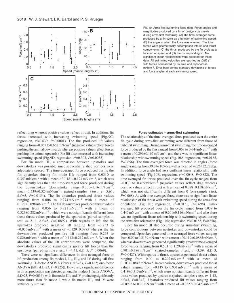
Force estimates – arms-first swimmingThe relationships of the time-averaged force produced over the entirefin cycle during arms-first swimming were different from those oftail-first swimming. During arms-first swimming, the time-averagedforce produced by the fins ranged from 0.068 to 0.644mNcm–2 witha mean of 0.299±0.167mNcm–2, and there was no significant linearrelationship with swimming speed (Fig.10A; regression, r20.0185,P0.656). The time-averaged force was directed in angles (forceangle) ranging from 39.8 to 105deg with a mean of 76.26±22.28deg.In addition, force angle had no significant linear relationship withswimming speed (Fig.10B; regression, r20.0048, P0.822). Thetime-averaged fin thrust produced over the fin cycle ranged from–0.030 to 0.465mNcm–2 (negative values reflect drag whereaspositive values reflect thrust) with a mean of 0.088±0.158mNcm–2,which was not significantly different from 0 (one-sample t-test,P0.068). As with time-averaged force, there was no significant linearrelationship of fin thrust with swimming speed during the arms-firstorientation (Fig.10C; regression, r20.0151, P0.698). Time-averaged lift produced over the fin cycle ranged from 0.039 to0.445mNcm–2 with a mean of 0.201±0.116mNcm–2 and also therewas no significant linear relationship with swimming speed duringthe arms-first orientation (Fig.10D; regression, r20.0185, P0.658).
Since fin mode III also occurred during arms-first swimming,force contributions between upstrokes and downstrokes could becompared. Upstrokes generated time-averaged force values rangingfrom 0.00 to 0.2139mNcm–2 with a mean of 0.119±0.0885mNcm–2,whereas downstrokes generated significantly greater time-averagedforce values ranging from 0.501 to 1.29mNcm–2 with a mean of0.901±0.386mNcm–2 (paired-samples t-test; t–3.39, d.f.3,P0.0427). With regards to thrust, upstrokes generated thrust valuesranging from 0.00 to 0.202mNcm–2 with a mean of0.103±0.0845mNcm–2. In comparison, downstrokes produced thrustvalues ranging from –0.119 to 0.931mNcm–2 with a mean of0.419±0.513mNcm–2, which were not significantly different fromthose values produced by upstrokes (paired-samples t-test, t–1.13,d.f.3, P0.342). Upstrokes produced lift values ranging from–0.0995 to 0.00mNcm–2 with a mean of –0.0527±0.0423mNcm–2
W. J. Stewart, I. K. Bartol and P. S. Krueger
0
0.2
0.4
0.6
0.8
1
0.5 1.5 2.51 20
0.2
0.4
0.6
0.8
1
0
0.2
0.4
0.6
0.8
1
0.5 1.5 2.51 2
A
DC
B
For
ce (
mN
cm
–2)
Thr
ust (
mN
cm
–2)
Lift
(mN
cm
–2)
Speed (mantle lengths s–1)
0
40
80
120
160
Ang
le (
deg)
0.5 1.5 2.51 2 0.5 1.5 2.51 2Speed (mantle lengths s–1)
Fig.10. Arms-first swimming force data. Force angles andmagnitudes produced by a fin of Lolliguncula brevisduring arms-first swimming. (A)The time-averaged forceproduced by a fin cycle as a function of swimming speed:(B) the angle in which the force was oriented. The totalforces were geometrically decomposed into lift and thrustcomponents: (C) the thrust produced by the fin cycle as afunction of speed and (D) the corresponding lift. Nosignificant linear relationships were detected for thesedata. All swimming velocities are reported as DMLs–1
with forces normalized by fin area and reported asmNcm–2. Error bars denote standard deviations of forcesand force angles at each swimming speed.
THE JOURNAL OF EXPERIMENTAL BIOLOGY

2019Hydrodynamic fin function of brief squid
while downstrokes produced lift values ranging from 0.328 to0.890mNcm–2 with a mean of 0.646±0.281mNcm–2. When theabsolute values of the lift contributions were compared, thedownstrokes produced significantly greater lift forces than theupstrokes (paired-samples t-test, t–5.78, d.f.3, P0.0103).
When fin force production was compared among fin swimmingmodes during the arms-first orientation, fin mode IIIA producedsignificantly more time-averaged force and thrust than mode IIA
[two sample one-tailed t-test (force), d.f.11, P0.0015;two sampleone-tailed t-test (thrust), d.f.11, P0.0113], while lift productionwas similar among fin modes (two sample two-tailed t-test, d.f.11,P0.0952).
Arms-first versus tail-first force valuesArms-first and tail-first fin force contributions were also comparedbased on eight similar swimming speeds (±0.07DMLs–1), rangingfrom 0.54 to 1.79DMLs–1. For the speeds considered, the finsproduced significantly more time-averaged force over the fin cycleduring tail-first swimming than during arms-first swimming (one-tailed paired sample t-test, d.f.7, P0.031). When this force wasgeometrically decomposed into thrust and lift, the fins producedsignificantly more thrust during tail-first swimming (one-tailedpaired sample t-test, d.f.7, P0.018) whereas there was nosignificant difference in lift production between orientations (two-tailed paired sample t-test, d.f.7, P0.19).
DISCUSSIONAlthough both the jet and fins are generally active during swimming,some previous locomotive studies on squid have largely ignored thefins as propulsors and focused primarily on the jet (Anderson andDeMont, 2000; Anderson and Grosenbaugh, 2005; Johnson et al.,1972; O’Dor, 1988). In the present study, vortex formation aroundfins was quantified using DPIV and fin force production wasestimated from vorticity fields for the first time in any cephalopod.
The results indicate that the fins of Lolliguncula brevis producehydrodynamically relevant forces when compared to the pulsatile jet(Fig.11), generating lift, thrust, and/or drag, in varying degrees,depending on swimming speed, and swimming orientation. Duringtail-first swimming, force data suggest the fins play an important rolein stability at low swimming speeds, often producing drag, whileshifting to greater thrust production as speed increases. Fin lift alsoincreases with swimming speed during tail-first swimming. Bycontrast, arms-first force data suggest neither fin thrust nor lift islinearly dependent on swimming speed and lift is the fins’ mainresponsibility. Moreover, L. brevis exhibited four qualitative fin wakepatterns, or swimming modes, each with distinctive vortex ringstructures, and overall demonstrated great versatility in locomotivefin function. Because the jet also produces locomotive forces, withthe arms providing some additional lift, the fins generate only a portionof a squid’s total thrust and lift. The variability in fin force productionand diversity in wake patterns observed in this study together withresults from Bartol et al. (Bartol et al., 2008) reflect the complexinterplay among the different systems.
Although the current study provides the first global quantitativedata from around squid fins, it is not the first study suggesting squidfins aid in locomotion. Zuev (Zuev, 1966) demonstrated thatSthenoteuthis oualaniensis and Illex illecebrosus achieve similarswimming velocities but have difficulty maintaining altitude andconsistent trajectories when their fins are amputated, suggesting thefins provide not only stability, but lift as well. By contrast, Webberand O’Dor (Webber and O’Dor, 1986) and O’Dor and Webber (O’Dorand Webber, 1991) later reported that the fins of Illex illecebrosusprovide negligible lift or thrust and function only in steering duringthe majority of swimming speeds, whereas the undulatory finmovements of Doryteuthis opalescens [formerly Loligo opalescens(see Vecchione et al., 2005)] augment locomotive forces only at verylow speeds, when the fin waves travel faster than the animal’s velocity.O’Dor (O’Dor, 1988) further investigated fin function and, at thelowest swimming speeds, estimated the fins provide up to 38% ofthe total thrust for Doryteuthis opalescens and 25% of the total thrustfor Illex illecebrosus, but do not aid in propulsion during moderateto high speeds. Hoar et al. (Hoar et al., 1994) later explored squid findiversity and predicted that, based on a heavy reliance on fin motionover a variety of swimming speeds, the fins of coastal squid areimportant propulsive contributors, providing supplemental thrust tothe jet. Anderson and DeMont (Anderson and DeMont, 2005) studiedkinematics of the squid Doryteuthis pealeii [formerly Loligo pealeii(see Vecchione et al., 2005)] and predicted the fins contribute a largeportion of total thrust needed for movement. Bartol et al. (Bartol etal., 2001b) further emphasized the importance of fins and estimatedhigh propulsive contributions based on force balance equations. Forexample, the fins of Lolliguncula brevis could potentially generateup to 83.8% of the total lift and 55.1% of the total thrust at low speeds.While these previous studies predicted fin force contributions basedon kinematics and force balance equations, the current study providesmore direct and quantitative measurements of force production usingDPIV data of the fin wake.
When considering a squid’s dual locomotive system, it is usefulto consider propulsive efficiency. A squid’s pulsatile jet is thoughtto be inherently less efficient than an undulating/oscillatory fin becauseof the volume limitations of the jet, although recent studies haveindicated that pulsed jets can also be efficient at high speeds and/orwhen pulses are short (Anderson and Grosenbuagh, 2005; Bartol etal., 2008; Bartol et al., 2009a; Bartol et al., 2009b). Whereas a fin isless volumetrically restrained and can displace a large volume of waterat low velocity, a jet often displaces a relatively small volume of water
For
ce (
mN
)
2.0
1.8
1.6
1.4
1.2
1.0
0.8
0.6
0.4
0.2
0
Size class
1 2 3
3.0
2.8
2.6
2.4
2.2
Fin thrust
Fin lift
Jet thrust
Jet lift
Fig.11. Forces produced by both lateral fins and the jet of Lolligunculabrevis swimming between 1 and 2DMLs–1. Black squares and circlesrepresent jet thrust and lift, respectively, and white squares and circlesrepresent fin thrust and lift, respectively. Jet force data courtesy of Bartol etal. (Bartol et al., 2009b). Size class 1: 4–4.9cm DML, size class 2:5–5.9cm DML, size class 3: 6–6.9cm DML. Error bars indicate ±1 s.e.m.
THE JOURNAL OF EXPERIMENTAL BIOLOGY
2020
housed in a volumetrically limited mantle at a higher speed to achievethe same thrust, which may be energetically costly (Vogel, 1994).This inverse relationship between jet velocity and propulsiveefficiency is reflected in the Froude efficiency equation:
where U is the swimming velocity and Uj is the jet velocity relativeto the swimmer (Vogel, 2003). Given that fin recruitmentpresumably provides propulsive efficiency gains, it is not surprisingthat fin thrust was detected in the current study.
The propulsive benefits of fin activity for L. brevis are mostsignificant for the speed range considered in this study. Bartol etal. (Bartol et al., 2008) reported the fins can increase overalllocomotive efficiency by as much as 10.2% when active. AlthoughL. brevis can swim at higher speeds than those examined in thecurrent study, fin activity drops precipitously and ceases altogetherat higher speeds (Bartol et al., 2001b). Given the presumedadvantages of fin motion, why does fin activity decrease andultimately cease as speed increases above the range explored here?Squid fins are tightly packed, three-dimensional muscular arraysknown as ‘muscular hydrostats’ (Kier, 1988; Kier, 1989; Kier andSmith, 1985). Unlike the fins of fishes or the wings of birds,muscular hydrostats contain no hard supporting structures such asfin rays or bones, respectively. Instead, the tightly packed musclesprovide both the force and support for movement (Kier, 1985).Although this arrangement allows for complex motions, the lack ofskeletal support limits force production and prevents the attainmentof high swimming speeds using fin propulsion alone (Kier, 1988;Kier, 1989; O’Dor and Webber, 1991). Consequently, the jetproduces a greater proportion of the overall thrust as speed increasesand fin force production declines (Bartol et al., 2001a; Bartol et al.,2001b; Bartol et al., 2008; O’Dor, 1988). When thrust productionno longer exceeds drag because of structural limitations of themuscular hydrostatic system, L. brevis and other squids often wraptheir fins around the mantle (Hoar et al., 1994; Bartol et al., 2001b)which provides a drag reduction benefit.
Fin wake patternsIn this study, four qualitatively distinct hydrodynamic fin wakesignatures, or fin modes, were observed, two of which occurred duringarms-first swimming and all four of which occurred during tail-firstswimming. The reduced number of hydrodynamic wake signaturesobserved in arms-first swimming (fin modes IIA and IIIA) relative totail-first swimming (fin modes I, IIT, IIIT, and IV) may relate todifferences in how the swimming orientations are employedecologically. The arms-first orientation is used most extensively atlow speeds when L. brevis is maneuvering in complex environmentsand investigating potential prey, whereas the tail-first orientation isused predominantly for sustained swimming (I.K.B., unpublishedobservation). Consequently, the constant flow characteristics of thewater tunnel environment favor tail-first swimming, which was indeedthe dominant orientation preference, and this fact alone may havecontributed to the observance of more tail-first wake signatures. Themore upstream location of the fins during tail-first swimmingcompared with arms-first swimming also leads to greater interactionof fin flows with the body, which could ultimately necessitate greaterneed for locomotive flexibility to enhance swimming efficiency(Weihs, 2002).
There are numerous references to animals with variablehydrodynamic signatures in the locomotive literature. In many
ηP =2U
U j + U, (10)
animals, unique wake signatures are attributed to differentlocomotive ‘gaits’. For example, a bluegill sunfish’s pectoral finsheds a single vortex during slow labriform swimming but producestwo linked vortices at higher speeds (Drucker and Lauder, 1999).In addition, many birds exhibit a slow closed vortex gait during lowspeeds or hovering and a continuous vortex gait at high speeds (fordetails, see Alexander , 2002), with other intermediate wake patternsoccurring as well (Spedding et al., 2003).
The concept of gaits has been applied successfully to terrestrial,aerial and aquatic locomotion. As speed increases, humans switchfrom walking to running, many birds switch from a closed tocontinuous vortex wake, and certain fish, such as Lepomis, switchfrom pectoral fin movements to body and caudal fin undulations(Alexander, 1989). No single locomotive style allows an animal toefficiently travel over a wide speed range. By employing differentgaits, an animal varies its locomotion patterns to better match musclepower with locomotor power requirements (Alexander, 1989; Webb,1993). The high density of water in relation to air, means that thethrust needed for aquatic propulsion increases much more rapidlywith speed than the thrust needed for aerodynamic propulsion.Consequently, aquatic swimmers, in particular, must employdifferent gaits over their speed range (Webb, 2006). The fourqualitatively unique fin wake patterns described in the present studycould represent different locomotive gaits. Squids employing variousfin gaits, even over the limited speed range investigated in the presentstudy, can better meet swimming power requirements to increaseefficiency (Webb, 1993). However, further study involving energeticmeasurements, electromyography, and/or more quantitativehydrodynamic metrics is necessary to determine if the fin wakepatterns observed in the present study are indeed fundamentallydistinct locomotive gaits.
The high number of fin wake patterns, or swimming modes,observed in the current study is probably attributable to the muscularhydrostatic system of the fins, whereby muscles are arranged incomplex architectures, allowing for vast ranges of movementwithout support from bones or fluid cavities. Fin consist of threemutually perpendicular orientations of musculature: transverse,dorsoventral, and longitudinal fibers (Kier, 1989). Transverse fibersrun horizontally from the base of the fin to the fin margin,dorsoventral fibers extend vertically from the fin’s ventral and dorsalsurfaces, and longitudinal fibers lie horizontally, parallel to the finchord. In addition, the transverse and dorsoventral muscle massescontain connective tissue fibers that potentially aid in support andprovide elastic energy storage. To induce a fin movement, all threemuscle fiber types simultaneously contract in different degrees toprovide both the force and support for movement. Because of thesquid’s sophisticated coordination of fin muscle contractions, themuscular hydrostatic system can generate a wide range of motionsthat ultimately produce complex wake patterns. In addition, thetransverse muscles contain two types of fibers with contrastingaerobic capacities (Kier, 1989). The aerobic, mitochondria rich fibersmost likely produce gentle undulations for low-speed swimmingwhereas the anaerobic glycolic fibers probably produce fin flappingat higher speeds (Kier, 1989; Kier et al., 1989). In addition, Johnsenand Kier (Johnsen and Kier, 1993) suggest that connective tissuefibers (as opposed to muscle fibers) provide passive muscularsupport during low amplitude/low frequency fin movements,potentially increasing fin efficiency at low speeds. According tothese predictions, the undulatory fin movements responsible for finmode II are likely to be driven primarily by aerobic muscle activity.However, future EMG studies that examine muscle activity in thetwo transverse fiber types are needed to corroborate this prediction.
W. J. Stewart, I. K. Bartol and P. S. Krueger
THE JOURNAL OF EXPERIMENTAL BIOLOGY

2021Hydrodynamic fin function of brief squid
Each of the four swimming modes has potential advantages forvarious swimming speeds and/or orientations. During slowswimming or hovering, a squid needs low thrust for forwardmovement but still requires significant lift to counteract negativebuoyancy and maintain altitude. Fin mode I, which was detectedat relatively low speeds (0.19–0.54DMLs–1), involvedhydrodynamically inactive fin upstrokes, which is beneficial sincehydrodynamically active upstrokes often produce negative lift. Thefin downstrokes of fin mode I generated forces directed bothventrally and slightly opposite to the direction of motion, thusproducing significant lift and slight drag. Although this liftgeneration is important for depth maintenance at low speeds whenoverall dynamic lift is low (Bartol et al., 2001a), the drag producedcould possibly create an antagonistic force relationship with thethrust producing jet, thus increasing stability (Hoar et al., 1994).Negatively buoyant fish tilt their body at a slight angle of attack atlow swimming speeds, when trimming forces used for stabilitycontrol diminish. This behavior, known as ‘tilting,’ increases bodydrag, requiring propulsors to generate larger forces that better matchresistance and facilitate stability control (Webb, 1993). In squid,drag produced by the fins necessitates elevated thrust generationfrom the jet which can be used more effectively to correct self-imposed and external perturbations.
Fin mode IIT and IIA involved a seemingly linked vortex chaindominated by strong downstrokes producing ventrally directed forces,resulting in significant lift but minimal thrust production over fincycles. This suggests the fins primarily generated lift while the jetpresumably contributed the majority of thrust necessary for movementat speeds where this mode was employed. Because undulatory finmotion is required to produce the seemingly linked vortex chain infin mode II, its higher occurrence in arms-first swimming in the presentstudy is consistent with the findings of Bartol et al. (Bartol et al.,2001b), that there was greater undulatory fin motions in the arms-first mode than the tail-first mode. Moreover, the exclusive use ofmode IIA for low speed arms-first swimming is consistent withprevious studies that report highest reliance on undulatory fin motionsat low speeds in L. brevis (see Bartol et al., 2001b; Hoar, 1995).
Fin modes III and IV produced time-averaged forces that weremore horizontally directed than in fin modes I and II, resulting ingreater overall thrust production. In addition, both of these modesexhibited active upstrokes that also produced thrust at the cost ofinherent negative lift. Since both drag and lift forces increasequadratically with speed (FL � V2; FD � V2), modes that maximizethrust with each stroke rather than lift should be favored atintermediate and high speeds, which was generally the case withfin modes III and IV in the present study, i.e. modes IIIT and IVT
were employed more frequently at higher speeds during tail-firstswimming and mode IIIA was employed more frequently at higherspeeds during arms-first swimming. Although both modes wereemployed at some overlapping speeds during tail-first swimming,mode IV was generally used at higher speeds during tail-firstswimming, which may relate to its linked vortex structure. In modeIV, the shed upstream vortex of the downstroke served as thesubsequent downstream vortex of the upstroke, which couldpotentially accelerate upstroke vortex development and augmentcirculation, as is the case for insect wings (Birch and Dickinson,2003). This circulation augmentation would lead to enhancedupstroke thrust production, which is advantageous for higher speeds.
Fin propulsive efficiency also helps explain the use of modes IIIand IV during higher speed swimming. In the tail-first orientation,swimming modes IIIT and IV had significantly higher fin propulsiveefficiencies than mode I. Since fin propulsive efficiency is based
on thrust, this result is not surprising. In mode I, the fins oftengenerated net drag while the animal swam at a certain speed, inwhich case fin propulsive efficiency was set to 0. In modes IIIT andIV, the fin generated net thrust at all speeds, causing fin propulsionefficiencies to be much higher than in modes I and IIT. It should benoted, however, that these efficiency calculations do not incorporatethe thrust contributions of the pulsatile jet and assume squid achievevarious swimming speeds from fin movements alone. Consequently,the fin propulsive efficiencies reported in the present study probablyoverestimate the efficiency that would be achieved by fin locomotionalone, but they are nonetheless useful for relative comparisons ofthe different modes.
During tail-first swimming, the fin propulsive efficiencies ofswimming mode IIIT were not significantly different from those ofmode IV. Therefore, in spite of the two qualitatively unique wakepatterns, both swimming modes served statistically similar roles inforward propulsion. This could be because (1) there are only slightdiscrepancies in the fin thrust contributions and subsequentefficiencies of the two modes, and a larger sample size would beneeded to separate any statistically significant variation, or (2) theunique wake patterns function similarly in thrust production, as theefficiency calculations suggest, but function differently in some otherfacet of locomotion, i.e. lift, stability, maneuverability, energeticsor muscle mechanics. For example, modes IIIT and IV could producedifferent magnitudes of stability-producing lateral forces, whichwere not considered in the current study, while maintaining similarthrust contributions. As stated above, the apparent vortex linkageof mode IV could enhance circulation development and subsequentthrust production (Birch and Dickinson, 2003), allowing a fin togenerate a given thrust at a lower energetic cost in comparison toa non-linked wake. Clearly, further investigation is needed todetermine why squid employ two qualitatively distinct swimmingmodes with seemingly similar propulsive efficiencies.
Fin force productionTail-first swimming
Squid use the tail-first swimming orientation over a wider range ofswimming speeds than arms-first swimming, from low speedcruising to escape jetting (Bartol et al., 2001b; O’Dor, 1988). Tail-first swimming is likely to be preferred for steady swimming because(1) there is minimal bending of the funnel, which avoids the volumeflux limitations encountered during arms-first swimming when thefunnel is significantly curved (Bartol et al., 2001b) and (2) the finsare at the leading edge of the body, which is more beneficial forstability than if they were located more posteriorly (Weihs, 2002).According to previous studies, the fins of L. brevis remain activeat low to moderate tail-first swimming speeds, but this activity tendsto decrease with higher speed before the fins eventually wrap aroundthe mantle to reduce drag at the highest speeds (Bartol et al., 2001b;Hoar et al., 1994). To achieve high swimming speeds, Bartol et al.(Bartol et al., 2001b) predicted that mantle contraction amplitudeand/or frequency increase to augment thrust since the propulsiverole of the fins declines. In addition, Bartol et al. (Bartol et al., 2001b)reported that these negatively buoyant swimmers maintain altitudein both arms-first and tail-first modes by directing the pulsatile jetdownwards, positioning the mantle and arms at high angles of attack,and employing fin activity.
During 88% of the tail-first swimming speeds, both the upstrokeand downstroke of a fin cycle were hydrodynamically active, i.e. non-zero swimming forces were detected. When considering a squid’snegative buoyancy and concomitant lift requirements, an activeupstroke may seem surprising because of its inherent negative lift
THE JOURNAL OF EXPERIMENTAL BIOLOGY

2022
production. However, an active upstroke allows for constant thrustproduction throughout the fin cycle, which is beneficial especially athigh speeds when large thrust forces are required. In addition, theentire fin cycle produced a net lift during 96% of the tail-firstswimming speeds, meaning the fin downstrokes generated sufficientlift to cancel out the negative lift produced by the respective upstrokes(see Fig.9D). During fast forward flight, many birds exhibit a closedvortex gait, whereby a wake of linked vorticity is shed during bothwing upstrokes and downstrokes. In contrast to the squid’s upstroke,a bird’s upstroke produces continuous lift during the closed vortexgait as a result of circulation that remains bound to the wing (Rayner,1993). This disparity may relate to key differences in wing/finmorphology and lift requirements between birds and squids, whichgenerate lift differently (wing flapping versus fin, jet, and armcoordination) and locomote in dissimilar media (air versus water).
In the squid Doryteuthis pealeii, Anderson and DeMont(Anderson and DeMont, 2005) predicted that both fin upstrokes anddownstrokes produce thrust, with downstrokes generally producingthe majority of thrust over the fin cycle, especially at higher speeds.By contrast, when fin thrust contributions were compared for modeIIIT in the present study, downstrokes produced thrust values thatwere not significantly different from those produced by upstrokes.However, these data only reflect a single fin mode over a limitedportion of the speed range of L. brevis, and further comprehensivethrust comparisons between fin strokes across a wider speed rangeare necessary for L. brevis. Thrust comparisons between upstrokesand downstrokes during modes I, IIT, IIA, and IV were not possiblein the present study because of closely spaced, interacting vorticityshed from sequential strokes.
In the current study, the entire fin cycle produced thrust valuesthat increased with swimming speed in the tail-first orientation.Bartol et al. (Bartol et al., 2001b) also predicted the fins of L. breviscontribute more thrust as swimming speed increases, over a similarrange of speeds, although the jet produces disproportionately morethrust than the fins as speeds increase beyond the range investigatedhere (Bartol et al., 2001b; Bartol et al., 2008). As mentioned earlier,this complement to the jet, i.e. fin activity, increases overallpropulsive efficiency within this intermediate range where the finsare active (Bartol et al., 2008).
Fin cycles also produced lift values that increased with swimmingspeed during the tail-first orientation. Although lift generation isimportant for negatively buoyant swimmers such as L. brevis, thispositive correlation between lift and swimming speed is surprising.Since lift scales quadratically with velocity (FL � V2), active orpowered lift expenditure should decrease with increased speed. Oneexplanation may involve activity of the squid’s pulsatile jet. Bartolet al. (Bartol et al., 2001b; Bartol et al., 2009b) found that, at lowswimming speeds, the pulsatile jet provides significant lift bydisplacing fluid downwards, whereas, at higher speeds, L. brevisorients the jet more horizontally to maximize thrust production andpropulsive efficiency while providing minimal lift. To compensate,the fins are potentially recruited to generate a larger proportion ofthe animal’s required lift at high swimming speeds. While thisexplanation seems likely for a swimmer employing a duallocomotive system, further investigation of the relative contributionsof the fins and the jet is needed for confirmation.
Fin drag production during low speed tail-first swimming may wellbe a mechanism to enhance stability. At low speeds, trimming forcesin aquatic animals become poorly matched to those needed to correctdisturbances (Webb, 1993; Webb, 2006). To compensate for reducedeffectiveness of trimming forces at low speeds, some fishes flex theirfins to increase effector area and drag (Bone et al., 1995), whereas
others pitch to increase angle of attack of trim devices and hence lift(Ferry and Lauder, 1996; He and Wardle, 1986; Webb, 1993; Wilgaand Lauder, 2000). The elevated drag of the fin downstroke coupledwith high mantle and arm angles at low speeds (Bartol et al., 2001b)may serve a similar function. Several fish locomotion studies havereported pectoral fins functioning in non-thrust roles while swimming,providing stability benefits (Drucker and Lauder, 1999; Drucker andLauder, 2000; Drucker and Lauder, 2002; Drucker and Lauder, 2003)(for a review, see Drucker et al., 2006). Therefore, tail-first findownstrokes seemingly undergo a locomotive shift with increasingspeed, from stabilizers at low speed cruising to propulsors at higherspeeds, all while generating net lift.
Arm-first swimmingIn comparison to tail-first swimming, squid use arms-first swimmingover a more limited speed range, from hovering to only moderateswimming velocities, and prefer this orientation during complexmaneuvering, antagonistic encounters, and prey investigation (Bartol,1999). When in the arms-first orientation, squid have an expandedfield of view unobstructed by the large mantle (Bartol, 1999), andcan readily employ rapid prey strikes (Hanlon and Messenger, 1996).However, the funnel must undergo a 90deg or more bend to ejectwater posteriorly in the arms-first orientation, which constricts thefunnel and drastically limits the water volume flux of the jet andconcomitant force production (Bartol et al., 2001b). Because of thisreduced volume flux, Bartol et al. (Bartol et al., 2001b) predicted thatthe fins contribute more to thrust in the arms-first orientation thanthe tail-first orientation, although lift production is fairly similar inthese two modes. Data from the present study do not completelysupport this prediction. Lift production was not statistically differentfor the two swimming orientations, but the fins actually producedsignificantly more thrust during tail-first swimming than arms-firstswimming when similar swimming speeds were compared. Thisunexpected finding may relate to jet refilling. In the arms-firstorientation water can enter the mantle cavity during refilling easierthan in the tail-first orientation because it does not have to changedirection. This could allow for more frequent jets and greaterconcomitant jet thrust, resulting in reduced fin thrust requirementsduring arms-first swimming. Although it was not possible toinvestigate relative fin and jet thrust contributions with our planarDPIV setup, future studies with a 3-D volumetric flow quantificationsystem capable of simultaneously quantifying fin and jet flows couldprovide the data needed to address this hypothesis.
Fin cycles produced positive mean thrust and lift forces for thearms-first swimming speed range. Unlike tail-first swimming,however, the relationships of with swimming speed with the totalforce, lift and thrust produced by fin cycles in the arms-firstorientation were not linear. This could relate to two factors: (1) thereis a high level of variability in the data because of flexibility of thesquid’s dual locomotive system or (2) the fins occupy a specificlocomotive role that stays fairly constant for the speed rangeconsidered in this study. During arms-first swimming, the arm andjet positioning are more variable than during tail-first swimming(I.K.B., unpublished data), and this could lead to accompanyingvariability in fin force production, making it difficult to detectconsistent differences with speed. The detection of only two finmodes and high lift but low thrust production during arms-firstswimming lend support for the second factor.
Several fin characteristics of arms-first swimming suggest thatproducing lift, rather than thrust, is the main locomotiveresponsibility of the fins in this orientation. First, the fin cyclesproduced positive net lift during all speeds of arms-first swimming
W. J. Stewart, I. K. Bartol and P. S. Krueger
THE JOURNAL OF EXPERIMENTAL BIOLOGY

2023Hydrodynamic fin function of brief squid
(see Fig.10D). In spite of hydrodynamically active fin upstrokesinherently producing negative lift during many speeds, a net liftwas still achieved by strong downstrokes displacing fluid downwardsat high angles. Second, the fins produced negative thrust (drag) morefrequently in the arms-first orientation than in the tail-first orientation(the fins produced drag during 38% and 17% of the swimmingspeeds while in the arms-first and tail-first orientations, respectively).In fact, the fins produced no significant thrust when averaged overthe speed range during arms-first swimming. Third, unlike tail-firstswimming, fin thrust production did not increase with swimmingspeed in the arms-first orientation, suggesting the fins are notrecruited for thrust production to achieve higher speeds.
Upwardly directed fin forces (lift) may be particularly importantfor stability in the arms-first orientation. During arms-firstswimming, the pulsed jet is directed along an axis that is fartherfrom the center of mass than during tail-first swimming, resultingin greater pitching moments (Fig.12). For example, upwardlydirected fin forces may produce moments posterior to the squid’scenter of mass (Fig.12B). These moments can counter positivepitching moments created by the pulsed jet, which directs flowdownward, rearward and anterior to the center of mass. Althoughthe exact magnitudes of these pitching moments remain unknown,this pitch correcting system would be particularly advantageous overthe low speed range investigated in the present study where stabilitycontrol is most difficult (Webb, 2006).
Future directionsThe two-dimensional flow quantification analysis presented in thisstudy has several limitations. Two-dimensional force data relied onthe axisymmetric assumption, treating each vortex pair as a symmetricring. Although 2-D DPIV provides important information on wakedynamics, true 3-D flow analysis is necessary to more confidentlydistinguish between different swimming modes and to accuratelyreconstruct wake signatures. In the current study, 2-D DPIV datasuggest that vortex merging occurs in modes II and IV, but only withtrue volumetric global flow visualization and quantification data willthis be known for certain. New emerging technologies such asdefocusing digital particle image velocimetry (DDPIV) that allow fortrue volumetric flow visualization and quantification are on the horizonand hold great promise for addressing such areas (Gharib et al., 2002;Pereira and Gharib, 2002; Pereira and Gharib, 2004; Kajitani andDabiri, 2005; Pereira et al., 2006).
ConclusionsThis study provides the first quantitative global data set on fin flowsin actively swimming squids. Based on 2-D DPIV data, the finsgenerated both vertically and horizontally oriented forces of varyingdegrees depending on swimming speed and orientation. During tail-first swimming, the fins functioned as stabilizers at low speeds before
shifting to thrust generators as speed increased, all while generatingnet lift. During arms-first swimming, the fins primarily providedlift, with thrust production being secondary. Four principal fin wakepatterns were detected, each with a different vortex structure. Thiswake diversity indicates that the fins are versatile locomotivestructures, capable of matching locomotive force production withswimming requirements. Many studies involving squid swimmingdynamics have largely ignored the fins and focused primarily onthe jet, but the current data suggest the fins actively contribute tolocomotive force production and should be considered whenestimating overall squid swimming performance and energetics,especially for long-distance migrators. With the advent of newvolumetric flow quantification tools such as DDPIV, it may soonbe possible to study coordination between the jet and fins of squids,which is necessary for an integrated, comprehensive understandingof squid swimming.
LIST OF SYMBOLS AND ABBREVIATIONSâi unit vector aligned with the axis of vortex i vortex ring angleDDPIV defocusing digital particle image velocimetryDML dorsal mantle lengthDPIV digital particle image velocimetryE excess kinetic energyE–
f time-averaged rate at which excess kinetic energy is shedF time-averaged forceFD drag forceFL lift forceFL time-averaged liftFT time-averaged thrustI hydrodynamic impulse magnitudeI total hydrodynamic impulse vectorIx horizontal component of impulseIy vertical component of impulser radial coordinatet fin stroke periodu velocity vector fieldU swimming speedU mean swimming speedUj jet velocity relative to the swimmerV speedx position vectorti formation time of trailing vortex ihP propulsive efficiencyhP(fins) fin propulsive efficiencyr fluid densityy Stokes stream functionw vorticity vectorwq azimuthal component of vorticity
ACKNOWLEDGEMENTSWe gratefully acknowledge field assistance from Nathan Bowman, ChristopherSkaggs, and the Virginia Institute of Marine Science’s Eastern Shore Laboratory.
Flow A B Center of mass
AnteriorPosterior
Fig.12. Schematics illustrating the axis of the pulsatile jet in relation to a Lolliguncula brevis’ center of mass during tail-first (A) and arms-first (B) swimming.Straight blue arrows indicate the resultant forces produced by the pulsatile jet and the fin whereas curved red arrows indicate resultant pitching moments. InA, notice the axis of the jet force passes close to the squid’s center of mass. In B, the axis of the jet force is anterior to the center of mass, creating apositive pitching moment upstream of the head. Notice the near vertically oriented force generated by the fin produces a negative pitching moment thatpotentially balances the positive pitching moment of the jet.
THE JOURNAL OF EXPERIMENTAL BIOLOGY

2024
We would also like to thank M. Vecchione and two anonymous reviewers for theirhelpful comments. This research was funded by the National Science Foundation(IOS 0446229 to I.K.B., P.S.K. and J.T.T.) and the Thomas F. Jeffress and KateMiller Jeffress Memorial Trust (J-852 to I.K.B.).
REFERENCESAlexander, D. E. (2002). Nature’s Flyers. Baltimore: The Johns Hopkins University
Press.Alexander, R. M. (1989). Optimization and gaits in locomotion of vertebrates. Phys.
Rev. 69, 1199-1227.Anderson, E. J. and DeMont, M. E. (2000). The mechanics of locomotion in the squid
Loligo pealei: locomotory function and unsteady hydrodynamics of the jet andintramantle pressure. J. Exp. Biol. 203, 2851-2863.
Anderson, E. J. and DeMont, M. E. (2005). The locomotory function of the fins in thesquid Loligo pealei. Mar. Fresh. Behav. Phys. 38, 169-189.
Anderson, E. J. and Grosenbaugh, M. A. (2005). Jet flow in steadily swimming adultsquid. J. Exp. Biol. 208, 1125-1146.
Bartol, I. K. (1999). Distribution, Swimming Physiology, and Swimming Mechanics ofBrief Squid, Lolliguncula brevis. PhD. dissertation. The College of William and Mary,VA, USA, 214 pp.
Bartol, I. K., Mann, R. and Patterson, M. R. (2001a). Aerobic respiratory cost ofswimming in the negatively buoyant brief squid Lolliguncula brevis. J. Exp. Biol. 204,3639-3653.
Bartol, I. K., Patterson, M. R. and Mann, R. (2001b). Swimming mechanics andbehavior of the shallow-water brief squid Lolliguncula brevis. J. Exp. Biol. 204, 3655-3682.
Bartol, I. K., Mann, R. and Vecchione, M. (2002). Distribution of the euryhaline squidLolliguncula brevis in Chesapeake Bay: effects of selected abiotic factors. Mar. Ecol.Prog. Ser. 226, 235-247.
Bartol, I. K., Krueger, P. S., Thompson, J. T. and Stewart, W. J. (2008). Swimmingdynamics and propulsive efficiency of squids throughout ontogeny. Integ. Comp.Biol. 48, 720-733.
Bartol, I. K., Krueger, P. S., Stewart, W. J. and Thompson, J. T. (2009a). Pulsed jetdynamics of squid hatchlings at intermediate Reynolds numbers. J. Exp. Biol. 212,1506-1518.
Bartol, I. K., Krueger, P. S., Stewart, W. J. and Thompson, J. T. (2009b).Hydrodynamics of pulsed jetting in juvenile and adult brief squid Lolliguncula brevis:evidence of multiple jet ‘modes’ and their implications for propulsive efficiency. J.Exp. Biol. 212, 1889-1903.
Birch, J. M. and Dickinson, M. H. (2003). The influence of wingwake interactions onthe production of aerodynamic forces in flapping flight. J. Exp. Biol. 206, 2257-2272.
Bone, Q., Marshall, N. B. and Blaxter, J. H. S. (1995). Biology of Fishes. New York:Chapman and Hall.
Drucker, E. G. and Lauder, G. V. (1999). Locomotor forces on a swimming fish:three-dimensional vortex wake dynamics quantified using digital particle imagevelocimetry. J. Exp. Biol. 202, 2393-2412.
Drucker, E. G. and Lauder, G. V. (2000). A hydrodynamic analysis of fish swimmingspeed: wake structure and locomotor force in slow and fast labriform swimmers. J.Exp. Biol. 203, 2379-2393.
Drucker, E. G. and Lauder, G. V. (2001). Wake dynamics and fluid forces of turningmaneuvers in sunfish. J. Exp. Biol. 204, 431-442.
Drucker, E. G. and Lauder, G. V. (2002). Experimental hydrodynamics of fishlocomotion: functional insights from wake visualization. Integ. Comp. Biol. 42, 243-257.
Drucker, E. G. and Lauder, G. V. (2003). Function of pectoral fins in rainbow trout:behavioral repertoire and hydrodynamic forces. J. Exp. Biol. 206, 813-826.
Drucker, E. G., Walker, J. A. and Westneat, M. W. (2006). Mechanics of pectoral finswimming in fishes. In Fish Biomechanics (ed. R. E. Shadwick and G. V. Lauder),pp. 369-417. San Diego: Elsevier Academic Press.
Ferry, L. A. and Lauder, G. V. (1996). Heterocercal tail function in leopard sharks: athree dimensional kinematic analysis of two models. J. Exp. Biol. 199, 2253-2268.
Gharib, M., Pereira, F., Dabiri, J., Hove, J. and Modarress, D. (2002). Quantitativeflow visualization toward a comprehensive flow diagnostic tool. Integ. Comp. Biol. 42,964-970.
Hanlon, R. T. and Messenger, J. B. (1996). Cephalopod Behaviour. Cambridge:Cambridge University Press.
Hanlon, R. T., Hixon, R. F. and Hulet, W. H. (1983). Survival, growth, and behavior ofthe loliginid squid Loligo plei, Loligo pealei, and Lolliguncula brevis (Mollusca:Cephalopoda) in closed seawater systems. Biol. Bull. 165, 637-685.
He, P. and Wardle, C. S. (1986). Tilting behavior of the Atlantic mackerel, Scomberscombrus, at low swimming speeds. J. Fish Biol. 29, 223-232.
Hoar, J. A. (1995). The Changing Role of Fins in Growing Loliginid Squid (Mollusca;Cepholopoda). PhD dissertation, Dalhousie University, Halifax, Nova Scotia, 98 pp.
Hoar, J. A., Sim, E., Webber, D. M. and O’Dor, R. K. (1994). The role of fins in thecompetition between squid and fish. In Mechanics and Physiology of AnimalSwimming (ed. L. Maddock, Q. Bone and J. M. V. Rayner), pp. 27-43. Cambridge:Cambridge University Press.
Johnsen, S. and Kier, W. M. (1993). Intramuscular crossed connective tissue fibres:skeletal support in the lateral fins of squid and cuttlefish (Mullusca: Cephalopoda). J.Zool. Lond. 231, 311-338.
Johnson, W., Soden, P. D. and Trueman, E. R. (1972). A study in jet propulsion: ananalysis of the motion of the squid, Loligo vulgaris. J. Exp. Biol. 56, 155-165.
Kajitani, L. and Dabiri, D. (2005). A full three-dimensional characterization ofdefocusing digital particle image velocimetry. Meas. Sci. Tech. 16, 790-804.
Kier, W. M. (1985) The musculature of squid arms and tentacles: ultrastructureevidence for functional differences. J. Morph. 185, 223-239.
Kier, W. M. (1988). The arrangement and function of molluscan muscle. In TheMollusca, Form and Function (ed. E. R. Trueman, M. R. Clarke and K. M. Wilbur),pp. 211-252. New York: Academic Press.
Kier, W. M. (1989). The fin musculature in cuttlefish and squid (Mollusca,Cephalopoda): morphology and mechanics. J. Zool. Lond. 217, 23-38.
Kier, W. M. and Smith, K. K. (1985). Tongues, tentacles and trunks: thebiomechanics of movement in muscular hydrostats. Zool. J. Linnean Soc. 83, 307-324.
Kier, W. M., Smith, K. K. and Miyan, J. A. (1989). Electromyography of the finmusculature of the cuttlefish Sepia officinalis. J. Exp. Biol. 143, 17-41.
Messenger, J. B., Nixon, M. and Ryan, K. P. (1985). Magnesium chloride as ananaesthetic for cephalopods. Comp. Biochem. Physiol. C Pharmacol. Toxicol.Endocrinol. 82, 203-205.
Müller, U. K., Van den Heuvel, B., Stamhuis, E. J. and Videler, J. J. (1997). Fishfoot prints: morphology and energetics of the wake behind a continuously swimmingmullet (Chelon labrosus Risso). J. Exp. Biol. 200, 2893-2906.
Müller, U. K., Stamhuis, E. J. and Videler, J. J. (2000). Hydrodynamics of unsteadyfish swimming and the effects of body size: comparing flow fields of fish larvae andadults. J. Exp. Biol. 203, 193-206.
O’Dor, R. K. (1982). The respiratory metabolism and swimming performance of thesquid, Loligo opalescens. Can. J. Fish. Aquat. Sci. 39, 580-587.
O’Dor, R. K. (1988). The forces acting on swimming squid. J. Exp. Biol. 137, 421-442.
O’Dor, R. K. and Webber, D. M. (1991). Invertebrate athletes: trade-offs betweentransport efficiency and power density in cephalopod evolution. J. Exp. Biol. 60, 93-112.
Peng, J., Dabiri, J. O., Madden, P. G. and Lauder, G. V. (2007). Non-invasivemeasurement of instantaneous forces during aquatic locomotion: a case study of thebluegill sunfish pectoral fin. J. Exp. Biol. 210, 685-698.
Pereira, F. and Gharib, M. (2002). Defocusing digital particle image velocimetry andthe three-dimensional characterization of two-phase flows. Meas. Sci. Technol. 13,683-694.
Pereira, F. and Gharib, M. (2004). A method for three-dimensional particle sizing intwo-phase flows. Meas. Sci. Technol. 15, 2029-2038.
Pereira, F., Stüer, H., Graff, E. C. and Gharib, M. (2006). Two-frame 3d particletracking. Meas. Sci. Technol. 17, 1680-1692.
Rayner, J. M. V. (1993). On aerodynamics and the energetics of vertebrate flappingflight. Cont. Math. 141, 351-400.
Saffman, P. G. (1992). Vortex Dynamics. Cambridge, UK: Cambridge UniversityPress.
Spedding, G. R., Rosén, M. and Hedenström, A. (2003). A family of vortex wakesgenerated by a thrush nightingale in free flight in a wind tunnel over its entire naturalrange of flight speed. J. Exp. Biol. 206, 2313-2344.
Tytell, E. D. (2004). The hydrodynamics of eel swimming. I. Wake structure. J. Exp.Biol. 207, 1825-1841.
Vecchione, M., Young, R. E., Guerra, A., Lindsay, D. J., Clague, D. A., Bernhard,J. M., Sager, W. W., Gonzalez, A. F., Rocha, F. J. and Segonzac, M. (2001).Worldwide observations of remarkable deep-sea squids. Science 294, 2505-2506.
Vecchione, M., Roper, C. E., Widder, E. A. and Frank, T. M. (2002). In situobservations on three species of large-finned deep-sea squids. Bull. Mar. Sci. 71,893-901.
Vecchione, M., Shea, E., Bussarawit, S., Anderson, F., Alexeyev, D., Lu, C. C.,Okutani, T., Roeleveld, M., Chotiyaputta, C., Roper, C. et al. (2005). Systematicof Indo-West Pacific loliginids. Phuket Mar. Biol. Cent. Res. Bull. 66, 23-26.
Vogel, S. (1994). Life in Moving Fluids, 2nd edn. Princeton, NJ: Princeton UniversityPress.
Vogel, S. (2003). Comparative Biomechanics. Princeton, NJ: Princeton UniversityPress.
Webb, P. W. (1993). Is tilting behaviour at low swimming speeds unique to negativelybuoyant fish? Observations on steelhead trout, Oncorhynchus mykiss, and bluegill,Lepomis macrochirus. J. Fish Biol. 43, 687-694.
Webb, P. W. (2006). Stability and maneuverability. In Fish Biomechanics (ed. R. E.Shadwick and G. V. Lauder), pp. 369-417. San Diego: Elsevier Academic Press.
Webber, D. M. and O’Dor, R. K. (1986). Monitoring the metabolic rate and activity offree-swimming squid with telemetered jet pressure. J. Exp. Biol. 126, 205-224.
Weihs, D. (2002). Stability versus maneuverability in aquatic locomotion. Int. Comp.Biol. 42, 127-134.
Wilga, C. D. and Lauder, G. V. (2000). Three-dimensional kinematics and wakestructure of the pectoral fins during locomotion in leopard sharks, Triakissemifasciata. J. Exp. Biol. 203, 2261-2278.
Willert, C. E. and Gharib, M. (1991). Digital particle image velocimetry. Exp. Fluids.10, 181-193.
Zuev, G. V. (1966). Characteristic features of the structure of cephalopod molluscsassociated with controlled movements. Ekologo-Morfologicheskie IssledovaniyaNektonnykh Zhivotnykh. Kiev, Special Publication. (Canadian Fisheries and MarineServices Translation Series 1011, 1968).
W. J. Stewart, I. K. Bartol and P. S. Krueger
THE JOURNAL OF EXPERIMENTAL BIOLOGY