hydrogen sulfide analyzer model 330s & 331s model …€¦ · envent engineering ltd. hydrogen...
TRANSCRIPT

Envent Engineering Ltd.
Hydrogen Sulfide Analyzer
Model 330S & 331S
Model 330SDS & 331SDS
User's Manual
Revision 2.1
Dec 2017


Table of Content INTRODUCTION ...................................................................................................................................... 1
Contacting Envent Engineering Ltd............................................................................................................ 1
Canada Office: (Main) ............................................................................................................................ 1
USA Office: ............................................................................................................................................ 1
China Office: ........................................................................................................................................... 1
Warranty & Liability Statements ................................................................................................................ 2
Limitation of Warranty ........................................................................................................................... 2
Disclaimer ................................................................................................................................................... 2
Warnings & Cautions .................................................................................................................................. 3
Warning & Cautions for 330S & 331S H2S Analyzers .......................................................................... 3
Warning & Cautions for 330S Analyzer Only ........................................................................................ 4
Warning & Cautions for 331S H2S Analyzer Only ................................................................................ 5
Analyzer Certifications: Area Classification .............................................................................................. 5
Certification under CSA Standards Mark# MC 235646 ......................................................................... 5
Products........................................................................................................................................... 5
Applicable Requirements ................................................................................................................ 6
Certification under CSA Standards ETL Mark# 4002458 ...................................................................... 7
Products........................................................................................................................................... 7
Applicable Requirements ................................................................................................................ 8
Analyzer Specifications .............................................................................................................................. 8
Key Symbols ............................................................................................................................................. 10
PRINCIPLE OF OPERATION................................................................................................................. 11
Physical Reaction ...................................................................................................................................... 11
Analysis Cycles ......................................................................................................................................... 12
Dual Sensor Analysis cycle (SDS): ...................................................................................................... 14
ANALYZER COMPONENTS ................................................................................................................. 15
Controller Board ....................................................................................................................................... 15
Power Connection ................................................................................................................................. 15
Solenoid Output Drivers & Furnace Output ......................................................................................... 16
Dry Contact Relays ............................................................................................................................... 16
Analog Outputs ..................................................................................................................................... 16
Digital Inputs ........................................................................................................................................ 17
Serial Ports & I2C ................................................................................................................................. 18
LCD Display Board .................................................................................................................................. 18
Sample Chamber ....................................................................................................................................... 19
Sensor Block ......................................................................................................................................... 19
Window & Gasket................................................................................................................................. 20
Aperture Strip........................................................................................................................................ 20
Trigger Slide ......................................................................................................................................... 21
Sample flow Components ......................................................................................................................... 21
Flowmeter ............................................................................................................................................. 21
Humidifier Unit ..................................................................................................................................... 22
Eductor Block ....................................................................................................................................... 23
Sample Conditioning System .................................................................................................................... 24
Filter Housing, Pressure Regulator, & Pressure Gauge (Conventional) ............................................... 26
Filter Housing ............................................................................................................................... 26
Pressure Regulator ........................................................................................................................ 26
Pressure Gauge.............................................................................................................................. 26
Three-way valve............................................................................................................................ 26
Sweep Needle Valve ..................................................................................................................... 26
Envent IFR Filter Housing, Regulator, & Pressure Gauge (Alternative) ............................................. 27
Pressure Regulator and Filter Housing ......................................................................................... 27
Pressure Gauge.............................................................................................................................. 28
Three-way valve............................................................................................................................ 28
Sweep Needle Valve ..................................................................................................................... 28
Optional Components ............................................................................................................................... 29
Low H2S sensing Tape Sensor .............................................................................................................. 29
Low Pressure Switch............................................................................................................................. 29
Power AO Boards ................................................................................................................................. 30
Ethernet Communication Card ............................................................................................................. 30
INSTALLATION ..................................................................................................................................... 31
Installation Requirements ......................................................................................................................... 31
Electrical Requirements ........................................................................................................................ 31
Location for the System ........................................................................................................................ 31
Space Requirements .............................................................................................................................. 32
Sample Point Selection ......................................................................................................................... 33
Sample inlet & sample sweep ............................................................................................................... 33

Vent line ................................................................................................................................................ 33
Sample Volume & Flow Rate ............................................................................................................... 34
Receiving the Analyzer ............................................................................................................................. 35
Unpacking the Analyzer ....................................................................................................................... 35
Standard spare parts for 330S H2S analyzers:....................................................................................... 35
Standard spare parts for 331S H2S analyzers:....................................................................................... 36
Installation procedure & Start-up.............................................................................................................. 36
OPERATION & CONFIGURATION ...................................................................................................... 38
Analyzer Display Interface ....................................................................................................................... 38
Analyzer ICE Software Interface .............................................................................................................. 39
Introduction to the 330S/331S ICE Software ....................................................................................... 39
Safety Guidelines .................................................................................................................................. 40
Using the ICE Software ........................................................................................................................ 40
Connecting the Analyzer to a Computer Using the ICE Software ............................................... 40
Modify analyzer's Configuration .................................................................................................. 41
Discrete Input Configuration ........................................................................................................ 41
Analog & Discrete Output Configuration ..................................................................................... 42
Alarm Configuration ..................................................................................................................... 45
Archive Setup Configuration ........................................................................................................ 48
Retrieve Archives from the Analyzer ........................................................................................... 49
Display Configuration ................................................................................................................... 51
CALIBRATION PROCEDURES ............................................................................................................ 54
H2S Gas Calibration .................................................................................................................................. 54
Re-zero Sensor Procedure ......................................................................................................................... 55
MAINTENANCE ..................................................................................................................................... 57
H2S Sensing Tape Change Procedure ....................................................................................................... 57
Sample Conditioning System Cleaning Procedure ................................................................................... 58
Material List .......................................................................................................................................... 58
Procedure .............................................................................................................................................. 58
TROUBLESHOOTING ............................................................................................................................ 60
APPENDICES .......................................................................................................................................... 70
Modbus Registry ....................................................................................................................................... 70
Recommended Spare Parts List ................................................................................................................ 71
Chico A Sealing Compound: For sealing fittings in Hazardous Locations .............................................. 71
Safety Data Sheet for H2S Sensing Tape .................................................................................................. 72
Risk Assessment - Safety Information ...................................................................................................... 77
List of Figures
Figure 1. H2S Analyzer Principle of Operation Diagram ......................................................................... 12
Figure 2. H2S Analysis Cycle ................................................................................................................... 13
Figure 3. H2S Controller Board Front View (Customer Connections) ..................................................... 15
Figure 4. Relay & Solenoid Outputs ......................................................................................................... 16
Figure 5. AO 4-20 mA Output Wiring Options ........................................................................................ 17
Figure 6. RS-232 Serial Port wired to a Mini USB Female Connector .................................................... 18
Figure 7. 330S & 331S H2S Analyzer Graphic Display ........................................................................... 19
Figure 8. Sample Chamber (Exploded View) ........................................................................................... 19
Figure 9. Trigger Slide Installed on a 330S H2S Analyzer (Applicable for 331S Analyzers) ................. 21
Figure 10. Envent's Humidifier Unit for 330S & 331S ............................................................................ 22
Figure 11. Humidifier Unit Installed in a 331S H2S Analyzer ................................................................. 23
Figure 12. Eductor Block (Venturi Effect) ............................................................................................... 24
Figure 13. PI&D Diagram of Standard Sample System for 330S & 331S H2S Analyzers ...................... 25
Figure 14. Conventional Standard Sample System................................................................................... 27
Figure 15. Alternative Standard Sample System ...................................................................................... 28
Figure 16. Low H2S Sensing Tape Sensor ................................................................................................ 29
Figure 17. Internal & External Pressure Switches .................................................................................... 29
Figure 18. Analog Output Board .............................................................................................................. 30
Figure 19. Ethernet Communication Card ................................................................................................ 30
Figure 20. Space Requirements for the 330S & 331S H2S Analyzers ...................................................... 32
Figure 21. 331S Recommended Venting for 331S (Same as the 330S H2S Analyzer) ............................ 34
Figure 22. 330S Display (left) & 331S Display (right) ............................................................................ 38
Figure 23. ICE Software: Enable Communication ................................................................................... 41
Figure 24. ICE Software: Configuration: System IO Tab: Inputs Tab ..................................................... 42
Figure 25. ICE Software: Configuration: System IO Tab: Outputs Tab .................................................. 43
Figure 26. ICE Software: Configuration: Alarms Tab .............................................................................. 45
Figure 27. ICE Software: Adding Variable as an Alarm .......................................................................... 46
Figure 28. ICE Software: New Alarm Set-up ........................................................................................... 47
Figure 29. ICE Software: Configuration: Archive Setup Tab .................................................................. 48
Figure 30. ICE Software: Reports: Archives Tab ..................................................................................... 50
Figure 31. ICE Software: Configuration: Display Tab ............................................................................. 51
Figure 32. 331S & 331SDS H2S Sensing Tape Change Procedure (Applicable for 330S & 330SDS
Analyzers) ................................................................................................................................................. 57
List of Tables
Table 1. 330S/331S H2S Analyzer Specifications ..................................................................................... 9
Table 2. Aperture Strips & Ranges ........................................................................................................... 20
Table 3. Sample Volume and & Flow Rate .............................................................................................. 34
Table 4. Display Button Description/Function ......................................................................................... 38
Table 5. Display LED Description/Function ............................................................................................ 39
Table 6. Hydrogen Sulfide Properties ....................................................................................................... 77
Table 7. Hydrogen Sulfide Quantities & Health Effects .......................................................................... 77

Envent Engineering Ltd. Page 1 Revision 2.1
INTRODUCTION
This manual provides all the necessary information to install, operate and
maintain the 330S, 330SDS, 331S and 331SDS model H2S Analyzer units. This
manual is intended for all technical level users.
Throughout this document will be referring to the models 330S and 331S.
However, the information applies equally to the 330SDS and 3301SDS (Dual
sensor), unless otherwise stated. To clarify, the difference between an "S" model
and a "SDS" model analyzer is the second sensor the "SDS" has to measure H2S
giving it the capability to measure H2S from two different samples at the same
time; the DS stands for Dual Sensor.
The Envent 330S/331S H2S Analyzer is a uniquely rugged and simple design that
utilizes lead acetate based detection which provides a linear and interference-free
output of H2S concentration. This analyzer can measure a wide range of hydrogen
sulfide concentrations from parts per billion (ppb) concentrations to parts per
million (ppm) concentrations. With the addition of a dilution sample system, it
can read high concentrations in percentage up to 100%. There are other options
available such as the sample system for H2S analysis in liquids or the addition of a
hydrogen reaction furnace for total sulfur measurements.
Contacting Envent Engineering Ltd
This manual covers most of the important information the user is going to need to
install, operate and maintain the 330S/331S H2S Analyzers. If more information is
required, you can contact us at:
Canada Office: (Main)
Toll Free: 1 (877) 936 - 8368
Tel: (403) 253 - 4012
Fax: (403) 253 - 4016
Email: [email protected]
Hours of operation: Monday to Friday – From 8:00 am to 4:30 pm (Mountain
Time Zone). Offices closed on statutory holidays.
USA Office:
Tel: 1 (713) 567 - 4421
China Office:
Tel: (86) 138 - 0119 - 1148
For further information on our products and most updated manuals/product
catalog please visit: www.envent-eng.com

Envent Engineering Ltd. Page 2 Revision 2.1
Warranty & Liability Statements
Products manufactured and supplied by Envent Engineering Ltd unless otherwise
stated are warranted against defects in materials and workmanship for up to 18
months from the date of shipment or 12 months from date of start-up, whichever
occurs first. During the warranty period the manufacturer will, as its option, either
repair or replace products, which prove to be defective.
The manufacturer or its representative can provide warranty service at the buyer's
facility only upon prior agreement. In all cases the buyer has the option of
returning the product for warranty service to a facility designated by the
manufacturer or its representatives. The buyer shall prepay shipping charges for
products returned to a service facility, and the manufacturer or its representatives
shall pay for return of the products to the buyer. The buyer may also be required
to pay round-trip travel expenses and labour charges at prevailing labour rates if
warranty is disqualified for reasons listed below.
Limitation of Warranty
The foregoing warranty shall not apply to defects arising from:
• Improper or inadequate maintenance by the user;
• Improper or inadequate unpacking or site preparation/installation;
• Unauthorized modification or misuse;
• Operation of the product in unfavorable environments, especially high
temperature and/or high humidity;
• Corrosive or other damaging atmospheres or otherwise outside published
specifications of analyzer.
Envent Engineering Ltd carries no responsibility for damage cause by
transportation or unpacking, unless otherwise specified in the incoterms.
Extended warranty may be available with certified start-up. Contact Envent
Engineering Ltd for details.
Envent Engineering Ltd reserves the right to change the product design and
specifications at any time without prior notice.
Disclaimer
No other warranty is expressed or implied. The manufacturer specially disclaims
the implied warranties of merchantability and fitness for a particular purpose.
The sole remedy of the buyer shall in no case exceed the purchase price of the
analyzer.

Envent Engineering Ltd. Page 3 Revision 2.1
The manufacturer shall not be liable for personal injury or property damage
suffered in servicing the product. The product should not be modified or repaired
in a manner at variance with procedures established by the manufacturer.
Warnings & Cautions
This section covers all warnings and cautions for the 330S and 331S H2S
analyzers. They are divided into warnings and cautions applicable to both the
330S and 331S, only 330S, and only 331S H2S analyzers. Please read and
understand all statements as they are for your own safety when installing,
operating and maintaining the analyzer(s). Some of these statements are also
noted throughout the manual when relevant.
Warning & Cautions for 330S & 331S H2S Analyzers
Do not disconnect equipment unless power has been switched off or area is
known to be non-hazardous.
Turn off power before servicing. Ensure breakers are off before connecting or
disconnecting power supply.
Electrostatic Hazard – Backpan and Certification nameplate must be cleaned only
with a damp cloth to prevent static charging hazard.
Hydrogen Sulfide and/or other hazardous gases may be present under normal
operation – proper precaution and protective equipment is advised. Please refer to
"Risk Assessment - Safety Information" on page 77 for more information.
The analyzers input voltage range shown in Certification Nameplate (e.g., 120 –
240VAC) is limited when installing external devices (e.g., Solenoids).
Incorrect configuration of the analyzer may cause incorrect operation. Injury
and/or damage to facilities may occur. Check analyzer's functionality after
configuration changes have been made.
Total Sulfur Furnace reaches a temperature of up to 900 °C internally after
1 hour on. Do not touch external surface as it can reach up to 150 °C. Allow
enclosure 1 hour after powering down the analyzer to cool down before servicing.
The analyzer should be mounted in an area in which it is not exposed to vibration,
excessive pressure, temperature and/or environmental variations.
Disassembly of the pressure regulator and solenoids in the field is not advised.
Consult Envent Engineering Ltd if the regulator or solenoid appears
contaminated.

Envent Engineering Ltd. Page 4 Revision 2.1
Before resuming line pressure, be sure that all port connections, sample sweep
and sample conditioning system are securely installed.
All connections must be leaktight to ensure the effectiveness of the analyzer as
well as safety. The user is solely responsible for the product selection, safety and
warning requirements for the application. If the equipment is used in a manner not
specified by Envent Engineering Ltd, the protection provided by the equipment
may be impaired.
Do not use solvents, brake cleaners, soaps, detergents or rubbing alcohol to clean
up analyzer or sample system.
This unit requires a disconnect device rated 24 VDC and 5A max. It must be
protected by a circuit breaker rated 24 VDC and 5A max, and it is to be installed
in accordance with local electrical codes.
This unit requires a disconnect device rated 240 VDC and 5A max. It must be
protected by a circuit breaker rated 240 VDC and 5A max, and it is to be installed
in accordance with local electrical codes.
Envent Engineering H2S Sensing Tapes are suitalbe for use, if stored in the
original sealed package, for 10 years fron date of manufacture. Tapes should be
stored in a coll dry location. If the seal on the package has been broken in storage,
the H2S Sensing Tape should be discarded.
Warning & Cautions for 330S Analyzer Only
Substitution of components may impair intrinsic safety and suitability for Class I,
Division 1.
Open circuit before removing cover.
Ensure that the analyzer received is suitable for the electrical classification of the
installation site:
• The 330S is designed for Class I, division 1 Groups CD
or Groups BCD (Check Analyzer Nameplate)
The glass window on the XP enclosure must remain installed in order to maintain
area classification.
Seals not poured. Pour seals before energizing the circuit (See "Chico A Sealing
Compound: For sealing fittings in Hazardous Locations" on page 71 for further
details).
Analyzer may utilize an optional CCS, Model 646 Series pressure switch located
on the side of the XP enclosure:
• Dual seal, MWP 500psi
Envent Engineering Ltd. Page 5 Revision 2.1
• Annunciation is visible leakage from the pressure adjustment cover
(flow from this cover can indicate the possibility that a failed primary
seal condition could exist in the pressure switch).
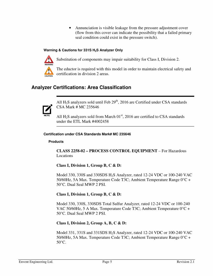
Warning & Cautions for 331S H2S Analyzer Only
Substitution of components may impair suitability for Class I, Division 2.
The eductor is required with this model in order to maintain electrical safety and
certification in division 2 areas.
Analyzer Certifications: Area Classification
All H2S analyzers sold until Feb 29th
, 2016 are Certified under CSA standards
CSA Mark # MC 235646
All H2S analyzers sold from March 01st, 2016 are certified to CSA standards
under the ETL Mark #4002458
Certification under CSA Standards Mark# MC 235646
Products
CLASS 2258-02 – PROCESS CONTROL EQUIPMENT – For Hazardous
Locations
Class I, Division 1, Group B, C & D:
Model 330, 330S and 330SDS H2S Analyzer, rated 12-24 VDC or 100-240 VAC
50/60Hz, 5A Max. Temperature Code T3C; Ambient Temperature Range 0°C +
50°C. Dual Seal MWP 2 PSI.
Class I, Division 1, Group B, C & D:
Model 330, 330S, 330SDS Total Sulfur Analyzer, rated 12-24 VDC or 100-240
VAC 50/60Hz, 5 A Max. Temperature Code T3C; Ambient Temperature 0°C +
50°C. Dual Seal MWP 2 PSI.
Class I, Division 2, Group A, B, C & D:
Model 331, 331S and 331SDS H2S Analyzer, rated 12-24 VDC or 100-240 VAC
50/60Hz, 5A Max. Temperature Code T3C; Ambient Temperature Range 0°C +
50°C.
Envent Engineering Ltd. Page 6 Revision 2.1
Class I, Division 2, Group B, C & D:
Model 331, 331S, 331SDS Total Sulfur Analyzer, rated 12-24 VDC or 100-240
VAC 50/60Hz, 5 A Max. Temperature Code T3C; Ambient Temperature 0°C +
50°C.
CLASS 2258-82 – PROCESS CONTROL EQUIPMENT – For Hazardous
Locations – Certified to US Standards
Class I, Division 1, Group B, C & D:
Model 330, 330S and 330SDS H2S Analyzer, rated 12-24 VDC or 100-240 VAC
50/60Hz, 5A Max. Temperature Code T3C; Ambient Temperature Range 0°C +
50°C
Class I, Division 1, Group B, C & D:
Model 330, 330S, 330SDS Total Sulfur Analyzer, rated 12-24 VDC or 100-240
VAC 50/60Hz, 5 A Max. Temperature Code T3C; Ambient Temperature 0°C +
50°C
Class I, Division 2, Group A, B, C & D:
Model 331, 331S and 331SDS H2S Analyzer, rated 12-24 VDC or 100-240 VAC
50/60Hz, 5A Max. Temperature Code T3C; Ambient Temperature Range 0°C +
50°C
Class I, Division 2, Group B, C & D:
Model 331, 331S, 331SDS Total Sulfur Analyzer, rated 12-24 VDC or 100-240
VAC 50/60Hz, 5 A Max. Temperature Code T3C; Ambient Temperature 0°C +
50°C
Applicable Requirements
CSA Standard C22.2 No. 0-10 – General Requirements Canadian Electrical Code
Part II.
CSA Standard C22.2 No.0.4-M2004 – Bonding of Electrical Equipment
CSA Standard C22.2 No.30-M1986 – Explosion-Proof Enclosure for Use in Class
I Hazardous Locations.
CSA Standard C22.2 No.142-M1987 – Process Control Equipment
CSA Standard C22.2 No.157-M1992 – Intrinsically Safe and Non-Incendive
Equipment for Use in Hazardous Locations
Envent Engineering Ltd. Page 7 Revision 2.1
CSA Standard C22.2 No. 213-M1987 – Non-Incendive Electrical Equipment for
Use in Class I, Division 2 Hazardous Locations
ANSI-ISA 12.27.01-2011 – Requirements for Process Sealing Between Electrical
Systems and Flammable or Combustible Process Fluids
UL Standard 508, Seventeenth Edition – Industrial Control Equipment.
UL Standard 913, Seventh Edition – Intrinsically Safe Apparatus and Associated
Apparatus for use in Class I, II, III, Division 1, Hazardous (Classified) Locations
ANSI-ISA 12.12.01-2011 – Non-Incendive Electrical Equipment for Use in Class
I and II, Division 2 and Class III, Divisions 1 and 2 Hazardous (Classified)
Locations
UL Standard 1203, Fourth Edition – Explosion-Proof and Dust-Ignition-Proof
Electrical Equipment for Use in Hazardous (Classified) Locations
Certification under CSA Standards ETL Mark# 4002458
Products
Process Gas Analyzer certified for Canadian Standards:
330, 330S, and 330SDS - H2S Analyzer, Class I, Division 1, Groups BCD. Dual
Seal, MWP 2 PSI
Notes: 1) Equipment is only acceptable for use in Class I, Division 1, Groups C
and D when provisioned with Model XFA2 Pressure Switch
2) The Dual Seal MWP rating is applicable to the Sample Gas pressure present at
the Heating Chamber Assembly. Models may have an optional pressure sensor
installed which is separately identified as being Dual Seal, MWP 500 PSI
330, 330S, and 330SDS - Total Sulphur Analyzer, Class I, Division 1, Groups
BCD. Dual Seal, MWP 2 PSI
Note: The Dual Seal MWP rating is applicable to the Sample Gas pressure present
at the Heating Chamber Assembly. Models may have an optional pressure sensor
installed which is separately identified as being Dual Seal, MWP 500 PSI
331, 331S and 331SDS H2S Analyzer, Class I, Division 2, Groups A, B, C and D.
331, 331S and 331SDS Total Sulphur Analyzer, Class I, Division 2, Groups A, B,
C and D

Envent Engineering Ltd. Page 8 Revision 2.1
Process Gas Analyzer certified for US Standards:
330, 330S, and 330SDS - H2S Analyzer, Class I, Division 1, Groups BCD.
Note: Equipment is only acceptable for use in Class I, Division 1, Groups C and
D when provisioned with Model XFA2 Pressure Switch
330, 330S, and 330SDS - Total Sulphur Analyzer, Class I, Division 1, Groups
BCD
331, 331S, and 331SDS - H2S Analyzer, Class I, Division 2, Groups ABCD.
331, 331S, and 331SDS - Total Sulphur Analyzer, Class I, Division 2, Groups
BCD
Temperature code (all products): T3C
Ambient Temperature Range (all products): 0°C to 50 °C
Applicable Requirements
- Safety Requirements For Electrical Equipment For Measurement, Control, And
Laboratory Use – Part 1: General Requirements [UL 61010-1:2012
Ed.3+R:29Apr2016]
- Safety Requirements For Electrical Equipment For Measurement, Control, And
Laboratory Use – Part 1: General Requirements (R2017) [CSA C22.2#61010-1-
12:2012 Ed.3+U1;U2]
- Safety Requirements For Electrical Equipment For Measurement, Control, And
Laboratory Use - Part 2- 201: Particular Requirements For Control Equipment
[UL 61010-2-201:2014 Ed.1]
- Safety Requirements For Electrical Equipment For Measurement, Control, And
Laboratory Use - Part 2- 201: Particular Requirements For Control Equipment
[CSA/IEC 61010-2-201:2014 Ed.1]
- Intrinsically Safe And Non-Incendive Equipment For Use In Hazardous Locations
(R2016) [CSA C22.2#157:1992 Ed.3+G1;U2]
- Nonincendive Electrical Equipment For Use In Class I And II, Division 2 And
Class III, Divisions 1 And 2 Hazardous (Classified) Locations [CSA
C22.2#213:2016 Ed.2]
- Explosion-Proof Enclosures For Use In Class I Hazardous Locations (R2016)
[CSA C22.2#30:1986 Ed.3+G1;G2]
- ISA 12.27.01 Issued: 2011/01/01 Requirements for Process Sealing Between
Electrical Systems and Flammable or Combustible Process Fluids
- UL 913 Issue:2006 Ed.7+R:23-Sep-2011 Intrinsically Safe Apparatus and
Associated Apparatus for Use in Class I, II, and III, Division I, Hazardous
(Classified) Locations
- Nonincendive Electrical Equipment For Use In Class I And II, Division 2 And
Class III, Divisions 1 And 2 Hazardous (Classified) Locations [ISA 12.12.01:2016
Ed.7]
- Standard For Explosion-Proof And Dust-Ignition-Proof Electrical Equipment For
Use In Hazardous (Classified) Locations [UL 1203:2013 Ed.5 +R:16Oct2015]
Envent Engineering Ltd. Page 9 Revision 2.1
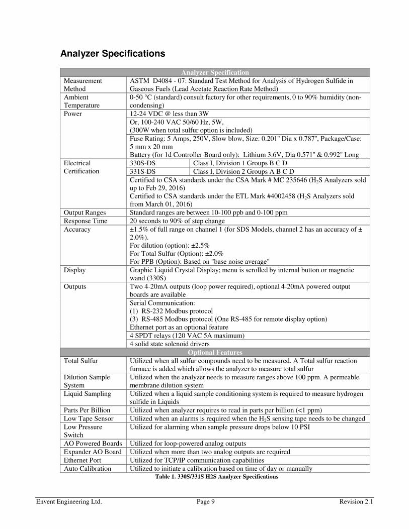
Analyzer Specifications
Analyzer Specification
Measurement
Method
ASTM D4084 - 07: Standard Test Method for Analysis of Hydrogen Sulfide in
Gaseous Fuels (Lead Acetate Reaction Rate Method)
Ambient
Temperature
0-50 °C (standard) consult factory for other requirements, 0 to 90% humidity (non-
condensing)
Power 12-24 VDC @ less than 3W
Or, 100-240 VAC 50/60 Hz, 5W,
(300W when total sulfur option is included)
Fuse Rating: 5 Amps, 250V, Slow blow, Size: 0.201'' Dia x 0.787'', Package/Case:
5 mm x 20 mm
Battery (for 1d Controller Board only): Lithium 3.6V, Dia 0.571'' & 0.992'' Long
Electrical
Certification
330S-DS Class I, Division 1 Groups B C D
331S-DS Class I, Division 2 Groups A B C D
Certified to CSA standards under the CSA Mark # MC 235646 (H2S Analyzers sold
up to Feb 29, 2016)
Certified to CSA standards under the ETL Mark #4002458 (H2S Analyzers sold
from March 01, 2016)
Output Ranges Standard ranges are between 10-100 ppb and 0-100 ppm
Response Time 20 seconds to 90% of step change
Accuracy ±1.5% of full range on channel 1 (for SDS Models, channel 2 has an accuracy of ±
2.0%).
For dilution (option): ±2.5%
For Total Sulfur (Option): ±2.0%
For PPB (Option): Based on "base noise average"
Display Graphic Liquid Crystal Display; menu is scrolled by internal button or magnetic
wand (330S)
Outputs Two 4-20mA outputs (loop power required), optional 4-20mA powered output
boards are available
Serial Communication:
(1) RS-232 Modbus protocol
(3) RS-485 Modbus protocol (One RS-485 for remote display option)
Ethernet port as an optional feature
4 SPDT relays (120 VAC 5A maximum)
4 solid state solenoid drivers
Optional Features
Total Sulfur Utilized when all sulfur compounds need to be measured. A Total sulfur reaction
furnace is added which allows the analyzer to measure total sulfur
Dilution Sample
System
Utilized when the analyzer needs to measure ranges above 100 ppm. A permeable
membrane dilution system
Liquid Sampling Utilized when a liquid sample conditioning system is required to measure hydrogen
sulfide in Liquids
Parts Per Billion Utilized when analyzer requires to read in parts per billion (<1 ppm)
Low Tape Sensor Utilized when an alarms is required when the H2S sensing tape needs to be changed
Low Pressure
Switch
Utilized for alarming when sample pressure drops below 10 PSI
AO Powered Boards Utilized for loop-powered analog outputs
Expander AO Board Utilized when more than two analog outputs are required
Ethernet Port Utilized for TCP/IP communication capabilities
Auto Calibration Utilized to initiate a calibration based on time of day or manually Table 1. 330S/331S H2S Analyzer Specifications
Envent Engineering Ltd. Page 10 Revision 2.1
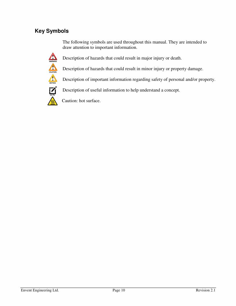
Key Symbols
The following symbols are used throughout this manual. They are intended to
draw attention to important information.
Description of hazards that could result in major injury or death.
Description of hazards that could result in minor injury or property damage.
Description of important information regarding safety of personal and/or property.
Description of useful information to help understand a concept.
Caution: hot surface.
Envent Engineering Ltd. Page 11 Revision 2.1
PRINCIPLE OF OPERATION
Physical Reaction
Envent's models 330S and 331S H2S analyzers use ASTM D4084 – 07: Standard
Test Method for analysis of hydrogen sulfide in gaseous fuels (Lead Acetate
reaction rate method). This method uses lead acetate impregnated paper.
Throughout this document the term lead acetate tape will be written as "H2S
sensing tape". Refer to "Safety Data Sheet for H2S Sensing Tape" on page 72 for
safety information on the H2S sensing tape.
The H2S sensing tape reacts when in contact with hydrogen sulfide by the
compound relationship shown below. This tape does not react to any other sulfur
compounds in the gas stream. This makes it free from interference when more
than one sulfur compound is present in the sample stream. The H2S reaction is
visibly evident by a brown stain directly on the H2S sensing tape.
COOHCHPbSCOOCHPbSHOH
3232 2)( 2+ →+
The electronics built into the models 330S and 331S have been programmed to
measure the rate of darkening over time which, in turn, gives the hydrogen sulfide
concentration level. When no H2S is in contact with the H2S sensing tape, the
analyzer sensor reads 1000 mV (+/- 100 mV).
The sensor block has a LED and a photodiode detector. The LED emits a red
beam of light which is reflected off of the H2S sensing tape to the photodiode
which detects the light intensity. The darker the H2S sensing tape becomes when
in contact to H2S, the less light the photodiode detector receives reducing the
millivolt value, which in turn, increases the H2S value. The "SDS" models
uniquely measures rate of change on both sides of the H2S sensing tape, allowing
for simultaneous readings of two separate samples.
Envent Engineering Ltd. Page 12 Revision 2.1
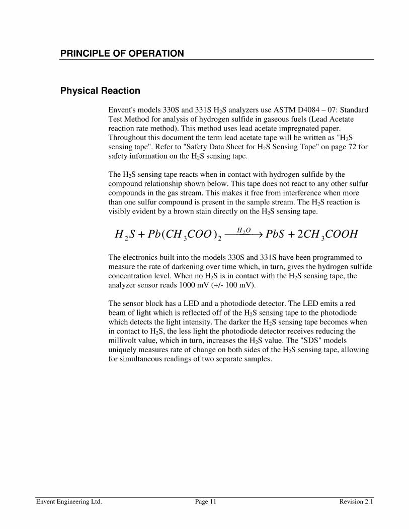
Figure 1. H2S Analyzer Principle of Operation Diagram
Figure 1 above shows a flow and pressure regulated of a filtered sample gas
passing through the humidifier into the sample chamber. An aperture in the
sample chamber, which differs in sizes depending on the application, allows the
gas to come in contact with the H2S sensing tape creating a brown stain.
Flow and pressure are the most important variables when measuring H2S and
must be kept at a constant state for the analyzer to measure H2S properly. Pressure
should be kept at a constant 15 psig. The lowest pressure found to be tolerable for
proper H2S measurement is 0.5 psig. Flow must be kept at a constant flow of 2 cm
(83.63 cc/min). A change in flow of +/- 1 cm affects the reading by 10% of full
range.
Analysis Cycles
The analysis of the color rate of change on the H2S sensing tape is measured in
analysis cycles. An analysis Cycle lasts up to a maximum of 720 seconds (12
minutes).
Do not change the Maximum Analysis Time, consult Envent Engineering Ltd.
Analyzers sold prior to Mid-August 2016 are set to have a 360 second analysis
cycle.

Envent Engineering Ltd. Page 13 Revision 2.1
Once an analysis cycle is complete, the motor moves the H2S sensing tape giving
the sensor block new tape surface area to start the analysis again. In normal
operation, if the analyzer is being exposed to H2S within its range, the analysis
cycle should last between 150 to 210 seconds (1.5 to 2.5 min); the cycle lasts 720
seconds if no H2S is present.
Figure 2. H2S Analysis Cycle
Figure 2 shows a complete analysis cycle from when the motor has advanced the
H2S sensing tape from a previous analysis (1), to the end of the current analysis
(4). Once the H2S sensing tape has finished moving and new tape surface area is
exposed, the reflection of light from the LED to the photodiode detector is at its
maximum and results in a voltage output from the sensor block of 1000 mV (+/-
100 mV). This voltage is captured by the analyzer and it is referred to as the "Zero
Voltage". The zero voltage will vary for each surface area of the H2S sensing tape
and will represent the starting point for the H2S reading for that cycle.
From stage (2) to (4) the H2S value starts increasing as the millivolt value drops
from exposure to H2S. This stage is called "RRA Analysis". The RRA stands for
Rapid Response Algorithm and it is the instantaneous H2S readings calculated
every 67 ms. As the H2S sensing tape darkens, the RRA value starts going up
every second. Although the RRA values are calculated almost instantaneously,
they are not as accurate as the final reading obtained at the "Concentration
Calculation" stage (3) to (4). However, RRA values can be used as a trigger
alarms setpoint in case the application requires a rapid response time (less than
the RRA Analysis completion). The first part of the RRA Analysis (2) to (3)

Envent Engineering Ltd. Page 14 Revision 2.1
completes when the mV value drops 100 mV. Once it drops 100 mV, stage (3) to
(4) "Concentration Calculation" starts.
On this stage, the H2S slope is optimal for calculating the final H2S value for that
Cycle. Algorithms are used by the controller board to calculate as accurately as
possible the H2S final value. Once the final value is obtained, it will stay at that
value (shown in the display and 4-20 mA analog outputs) until the next cycle has
finished and updates the H2S current reading. This stage will always be 1/5 of the
amount of time it takes stage (2) to (3) to complete. Thus, if stage (2) to (3) took
600 seconds, then stage (3) to (4) will take 120 seconds.
It is important that the analyzer is used for its calibrated H2S range. Do not use
this unit for an application that will require readings outside of its calibrated
range. This will cause the H2S sensing tape to run out faster and may cause less
accurate readings. The range is determined by the aperture strip in the sample
chamber. For more information analyzer ranges, refer to "Aperture Strip" on page
20.
Dual Sensor Analysis cycle (SDS):
Dual sensor analyzers have two sensors that read H2S from two different samples
at the same time, e.g. Sensor 1: 0-20 ppm H2S Sensor 2: 0-200 ppm H2S. The
analysis cycle process is the same per sensor as explained earlier in this section;
however, some extra algorithms have been implementing to help with the
interaction between the two sensors and their analysis cycles' timing.
Both analysis cycles for each sensor will always start at the same time. When the
motor moves and new H2S sensing tape area is exposed, a new analysis cycle has
started for both sensors. However, the analysis cycles from each sensor will finish
at different times. Either sensor 1 or sensor 2 will finish its analysis cycle first.
Regardless of which sensor finishes first, it will wait for the other sensor to
complete its analysis cycle. Once both sensors have completed their analysis
cycles, the motor will move and new H2S sensing tape area is exposed for a new
analysis cycle.
It is important to clarify that when the first sensor has finished its analysis cycle,
even when it is waiting for the second sensor to complete its analysis cycle, it
immediately updates any outputs associated with that sensor (Analog output 4-20
mA, alarms, display H2S value, etc.).

Envent Engineering Ltd. Page 15 Revision 2.1
ANALYZER COMPONENTS
In this section, the main components of the 330S/331S H2S analyzer will be
covered as well as the optional components added to the system at customer
request. A brief explanation of type, functionality, set up and options will be
described.
Total Sulfur and Dilution system options will not be covered in this section.
Please refer to Total Sulfur and Dilution manuals.
Controller Board
The H2S controller board is the most important electronic component of the
analyzer. It is a printed circuit board that holds all of the customer's connections
such as, communication ports, digital inputs, analog outputs, relay outputs
solenoid outputs, and AC or DC power input. Refer to Figure 3.
Power Connection
There are AC or DC H2S controller boards and will be specified by customer
request. The controller board with an AC power supply has an input voltage range
from 110 to 240 VAC (50-60 Hz) and the controller board with a DC power
supply has an input voltage range from 10 to 32 VDC. Refer to Figure 3.
Figure 3. H2S Controller Board Front View (Customer Connections)

Envent Engineering Ltd. Page 16 Revision 2.1
Solenoid Output Drivers & Furnace Output
The H2S controller board has four solenoid driver outputs. They operate at the
same voltage used to power the controller board and are used to directly drive
solenoids for shutdown, auto-calibration, stream switching, etc. The connection
F1-F1 is used to power up the furnace for Total Sulfur applications (Refer to
Figure 4).
Do not supply external power to solenoid drivers on the controller board.
Figure 4. Relay & Solenoid Outputs
Dry Contact Relays
The H2S controller board has four dry contact relays used as status outputs, to
drive external relays or solenoids. They are rated for a maximum of 120 VAC 5
Amp (Refer to Figure 4).
Analog Outputs
The H2S controller board has two isolated loop power 4-20mA outputs which can
be set up for different variable outputs. Loop power (10-32 Volts) sourced from
the end device (PLC) is required for the analog to output. Figure 5 shows the
different wiring set ups for the analog outputs.
The third wiring option shown in Figure 5 uses Envent's powered AO board(s) to
provide self-powered analog outputs. These boards are available at Envent
Engineering Ltd. Refer to "Power AO Boards" on page 30.
Envent Engineering Ltd. Page 17 Revision 2.1
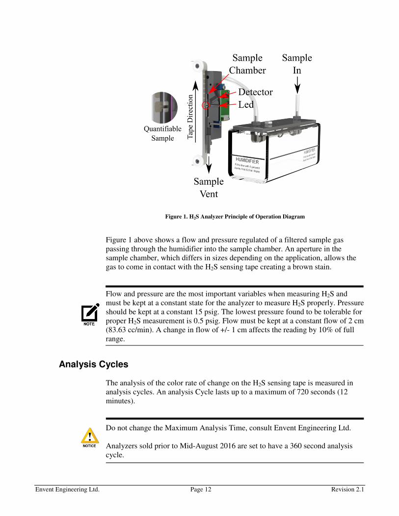
The factory default variable for the two analog outputs is the current H2S reading
on sample 1, labeled in the ICE software as "Sample 1 H2S – Current Value",
meaning both analog outputs are based on the H2S readings for sample 1. For
SDS models, analog output 2 outputs the variable for sample 2.
Figure 5. AO 4-20 mA Output Wiring Options
Digital Inputs
The H2S controller board has four digital inputs use to signal the analyzer of a
change of state from an external device, refer to Figure 3. As factory default,
DI#1 is used for low H2S sensing tape sensor and DI#2 is used for low pressure
Envent Engineering Ltd. Page 18 Revision 2.1
switch, if applicable. These two devices are installed to the analyzer only by
customer request.
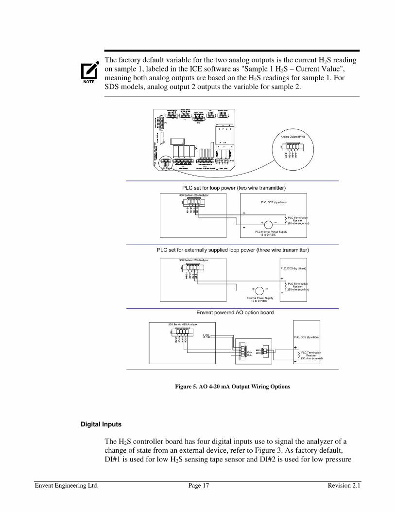
Serial Ports & I2C
The H2S controller board has the communication capabilities for RS-232, RS-485
and Ethernet (Optional). The RS-232 Serial port is wired to a mini USB Female
connector for easy access with an communication extension cable (provided with
analyzer) refer to Figure 6.
Figure 6. RS-232 Serial Port wired to a Mini USB Female Connector
The TCP/IP communication is achieved via a communication electronics card
which is connected to the I2C terminal block on the controller board. It does not
come with the analyzer unless otherwise requested by the customer. For more
information on the Ethernet communication card refer to "Ethernet
Communication Card" on page 30.
LCD Display Board
The LCD display board used for the H2S 330S/331S models is a graphic backlit
display with a direct tactile or magnetic interface, refer to Figure 7. The magnetic
interface is only used on the 330S H2S analyzers which are for Class I, Division 1
areas. The LCD display connects to the controller board with an IDC ribbon
cable.
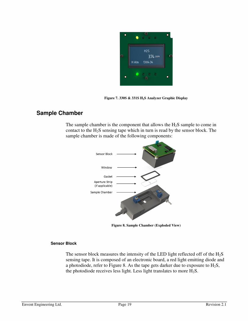
Envent Engineering Ltd. Page 19 Revision 2.1
Figure 7. 330S & 331S H2S Analyzer Graphic Display
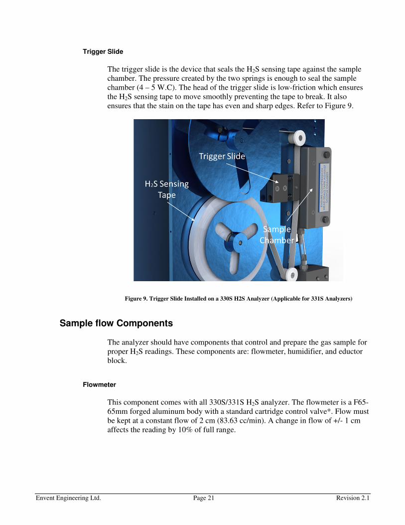
Sample Chamber
The sample chamber is the component that allows the H2S sample to come in
contact to the H2S sensing tape which in turn is read by the sensor block. The
sample chamber is made of the following components:
Figure 8. Sample Chamber (Exploded View)
Sensor Block
The sensor block measures the intensity of the LED light reflected off of the H2S
sensing tape. It is composed of an electronic board, a red light emitting diode and
a photodiode, refer to Figure 8. As the tape gets darker due to exposure to H2S,
the photodiode receives less light. Less light translates to more H2S.

Envent Engineering Ltd. Page 20 Revision 2.1
Window & Gasket
These two components seal the small compartment where the H2S comes inside
the sample chamber, refer to Figure 8. The window keeps a clear view for the
LED and the photodiode to work properly and isolates them from the sample gas.
The rubber gasket seals the Sample Chamber compartment preventing any leaks.
Aperture Strip
The sample chamber has a fixed size aperture of ¼ inch which is used for
concentrations in between 1 ppm to 16 ppm.
For concentration applications below 1 ppm or above 16 ppm an aperture strip is
installed behind the window in the Sample Chamber, refer to Figure 8. These
aperture strips keep the analysis time to be approximately the same regardless of
the range.
Various sizes of apertures match different measurement ranges. Table 2 shows the
aperture size according to its range.
H2S Range Aperture Strip Envent PN
50 ppb to 1 ppm ppb style 330110
1 ppm to 16 ppm None (1/4" fixed aperture size) N/A
16 ppm to 30 ppm 1/16" 330103
30 ppm to 50 ppm 1/32" 330102
50 ppm to 100 ppm Pin Holes 330100
100 ppm to 500 ppm Laser Dot 330109
Over 500 ppm Addition of a dilution panel. Consult Factory.
Table 2. Aperture Strips & Ranges
Aperture strips can be changed to accommodate for a different range application.
Refer to the table shown above to select the best option on the new concentration
application. Contact Envent Engineering Ltd to purchase an aperture strip.
Remember: gain and span values on analog outputs will have to change based on
new range application. Please re-calibrate analyzer. Refer to "H2S Gas
Calibration" on page 54.
The adhesive used to glue the aperture strip in its place is RTV108 Translucent
Adhesive. RTV102, RTV103, and RTV109 could also be used.
Envent Engineering Ltd. Page 21 Revision 2.1
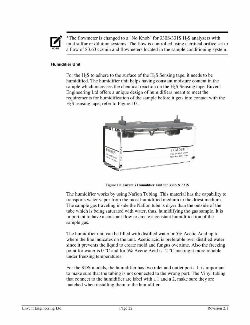
Trigger Slide
The trigger slide is the device that seals the H2S sensing tape against the sample
chamber. The pressure created by the two springs is enough to seal the sample
chamber (4 – 5 W.C). The head of the trigger slide is low-friction which ensures
the H2S sensing tape to move smoothly preventing the tape to break. It also
ensures that the stain on the tape has even and sharp edges. Refer to Figure 9.
Figure 9. Trigger Slide Installed on a 330S H2S Analyzer (Applicable for 331S Analyzers)
Sample flow Components
The analyzer should have components that control and prepare the gas sample for
proper H2S readings. These components are: flowmeter, humidifier, and eductor
block.
Flowmeter
This component comes with all 330S/331S H2S analyzer. The flowmeter is a F65-
65mm forged aluminum body with a standard cartridge control valve*. Flow must
be kept at a constant flow of 2 cm (83.63 cc/min). A change in flow of +/- 1 cm
affects the reading by 10% of full range.
Envent Engineering Ltd. Page 22 Revision 2.1
*The flowmeter is changed to a "No Knob" for 330S/331S H2S analyzers with
total sulfur or dilution systems. The flow is controlled using a critical orifice set to
a flow of 83.63 cc/min and flowmeters located in the sample conditioning system.
Humidifier Unit
For the H2S to adhere to the surface of the H2S Sensing tape, it needs to be
humidified. The humidifier unit helps having constant moisture content in the
sample which increases the chemical reaction on the H2S Sensing tape. Envent
Engineering Ltd offers a unique design of humidifiers meant to meet the
requirements for humidification of the sample before it gets into contact with the
H2S sensing tape; refer to Figure 10 .
Figure 10. Envent's Humidifier Unit for 330S & 331S
The humidifier works by using Nafion Tubing. This material has the capability to
transports water vapor from the most humidified medium to the driest medium.
The sample gas traveling inside the Nafion tube is dryer than the outside of the
tube which is being saturated with water, thus, humidifying the gas sample. It is
important to have a constant flow to create a constant humidification of the
sample gas.
The humidifier unit can be filled with distilled water or 5% Acetic Acid up to
where the line indicates on the unit. Acetic acid is preferable over distilled water
since it prevents the liquid to create mold and fungus overtime. Also the freezing
point for water is 0 °C and for 5% Acetic Acid is -2 °C making it more reliable
under freezing temperatures.
For the SDS models, the humidifier has two inlet and outlet ports. It is important
to make sure that the tubing is not connected to the wrong port. The Vinyl tubing
that connect to the humidifier are label with a 1 and a 2, make sure they are
matched when installing them to the humidifier.

Envent Engineering Ltd. Page 23 Revision 2.1
The analyzer should not be exposed to ambient temperatures lower than 0 °C.
By default, all 330S/331S H2S analyzers have a temperature alarm set to 0 °C
descending.
The analyzer should be mounted in an area in which it is not exposed to vibration,
excessive pressure, temperature and/or environmental variations.
Figure 11 shows know how to install the humidifier unit in a model 331S H2S
analyzer. Same principle applies for the model 330S H2S analyzer.
Figure 11. Humidifier Unit Installed in a 331S H2S Analyzer
Eductor Block
The analyzer reading can be affected by positive or negative pressure on the
sample vent line. This can be caused by strong winds blowing across or directly
into the vent; or by mechanical venting (exhaust fan). The eductor will eliminate
any influence on the analyzer reading; refer to Figure 12 .
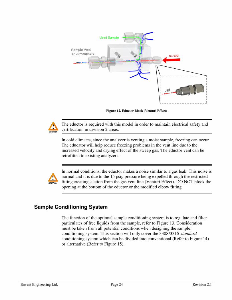
Envent Engineering Ltd. Page 24 Revision 2.1
Figure 12. Eductor Block (Venturi Effect)
The eductor is required with this model in order to maintain electrical safety and
certification in division 2 areas.
In cold climates, since the analyzer is venting a moist sample, freezing can occur.
The educator will help reduce freezing problems in the vent line due to the
increased velocity and drying effect of the sweep gas. The eductor vent can be
retrofitted to existing analyzers.
In normal conditions, the eductor makes a noise similar to a gas leak. This noise is
normal and it is due to the 15 psig pressure being expelled through the restricted
fitting creating suction from the gas vent line (Venturi Effect). DO NOT block the
opening at the bottom of the eductor or the modified elbow fitting.
Sample Conditioning System
The function of the optional sample conditioning system is to regulate and filter
particulates of free liquids from the sample, refer to Figure 13. Consideration
must be taken from all potential conditions when designing the sample
conditioning system. This section will only cover the 330S/331S standard
conditioning system which can be divided into conventional (Refer to Figure 14)
or alternative (Refer to Figure 15).

Envent Engineering Ltd. Page 25 Revision 2.1
Figure 13. PI&D Diagram of Standard Sample System for 330S & 331S H2S Analyzers
For special sample systems, refer to drawing package in the analyzer binder or
USB flash drive provided with the analyzer.
The standard sample conditioning system consists of:

Envent Engineering Ltd. Page 26 Revision 2.1
Filter Housing, Pressure Regulator, & Pressure Gauge (Conventional)
Filter Housing
The filter housing is capable of withstanding up to 5000 psig. This filter is set as
"Particulate" to better remove solid particles from the gas sample. For wet/dirty
systems, the filter is set as "Coalescent". The bonded microfiber filter element
located inside the filter housing should be changed at least every 3 months or as
required depending on the application.
Please contact Envent Engineering Ltd to order more bonded microfiber filters.
(Part No. 330406)
Pressure Regulator
The pressure regulator is a Swagelok 316SS 0-3600 psig Inlet and 0-25psig outlet
Series KPR.
Pressure Gauge
The Pressure gauge has a range of 0-30 psig. The pressure should be maintained
at 15 psig for normal operation. The lowest pressure found to be acceptable for
proper H2S measurement is 0.5 psig; however, it is not recommended to have a
lower pressure than 10 psig.
Three-way valve
It allows the user to manually switch from sample gas to calibration gas.
Sweep Needle Valve
This needle valve works by draining any liquids that may collect from the filter. It
also reduces lag time in the sample piping.
To learn more about lag time in the sample inlet please go to "Sample Volume &
Flow Rate" on page 34.
Envent Engineering Ltd. Page 27 Revision 2.1
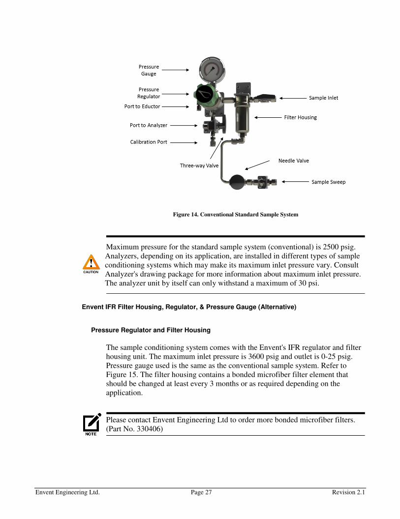
Figure 14. Conventional Standard Sample System
Maximum pressure for the standard sample system (conventional) is 2500 psig.
Analyzers, depending on its application, are installed in different types of sample
conditioning systems which may make its maximum inlet pressure vary. Consult
Analyzer's drawing package for more information about maximum inlet pressure.
The analyzer unit by itself can only withstand a maximum of 30 psi.
Envent IFR Filter Housing, Regulator, & Pressure Gauge (Alternative)
Pressure Regulator and Filter Housing
The sample conditioning system comes with the Envent's IFR regulator and filter
housing unit. The maximum inlet pressure is 3600 psig and outlet is 0-25 psig.
Pressure gauge used is the same as the conventional sample system. Refer to
Figure 15. The filter housing contains a bonded microfiber filter element that
should be changed at least every 3 months or as required depending on the
application.
Please contact Envent Engineering Ltd to order more bonded microfiber filters.
(Part No. 330406)
Envent Engineering Ltd. Page 28 Revision 2.1
Pressure Gauge
The Pressure gauge has a range of 0-30 psig. The pressure should be maintained
at 15 psig for normal operation. The lowest pressure found to be acceptable for
proper H2S measurement is 0.5 psig; however, it is not recommended to have a
lower pressure than 10 psig.
Three-way valve
It allows the user to manually switch from sample gas to calibration gas.
Sweep Needle Valve
This needle valve works by draining any liquids that may collect from the filter. It
also reduces lag time in the sample piping.
To learn more about lag time in the sample inlet please go to "Sample Volume &
Flow Rate" on page 34.
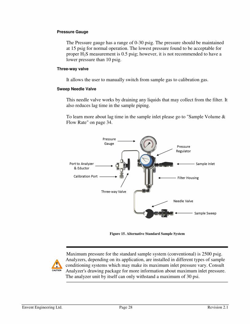
Figure 15. Alternative Standard Sample System
Maximum pressure for the standard sample system (conventional) is 2500 psig.
Analyzers, depending on its application, are installed in different types of sample
conditioning systems which may make its maximum inlet pressure vary. Consult
Analyzer's drawing package for more information about maximum inlet pressure.
The analyzer unit by itself can only withstand a maximum of 30 psi.

Envent Engineering Ltd. Page 29 Revision 2.1
Optional Components
Envent Engineering Ltd offers optional components that could be required for
certain applications. These components are:
Low H2S sensing Tape Sensor
Analyzers can automatically alarm when the H2S sensing tape is almost fully used
and needs to be changed for a new one. It alarms when the tape has 2 – 5 days left
remaining on the roll. This sensor is installed at customer request or it can be
obtained after purchase. Refer to Figure 16.
Figure 16. Low H2S Sensing Tape Sensor
Please contact Envent Engineering Ltd to order a low H2S sensing tape sensor.
(Part No. 330046A)
The low H2S sensing tape sensor is wired to DI#1 in the controller board by
default. Low tape alarm is configured to change state of Relay#4, Fault LED, and
Virtual#1 for standard configurations.
Low Pressure Switch
Analyzer with low pressure switch(es) alarm when the sample inlet pressure drops
below 10 psig. Pressure switch(es) are installed at customer request. It is wired to
DI#2 by default in a Fail Safe configuration. Low pressure alarm is configured to
change state of Relay#4, and Fault LED for standard configurations.
Figure 17. Internal & External Pressure Switches
Envent Engineering Ltd. Page 30 Revision 2.1
There are two types of pressure switches available. Internal pressure switch and
external pressure switch; refer to Figure 17. Both styles can be used for both the
330S and 331S H2S analyzers. If the internal switch is used on the 330S H2S
analyzer (division 1), a flame arrestor is used to comply with regulation standards.
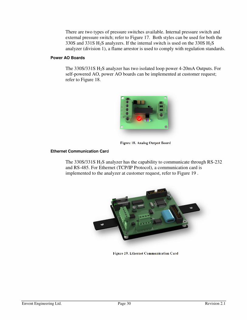
Power AO Boards
The 330S/331S H2S analyzer has two isolated loop power 4-20mA Outputs. For
self-powered AO, power AO boards can be implemented at customer request;
refer to Figure 18.
Figure 18. Analog Output Board
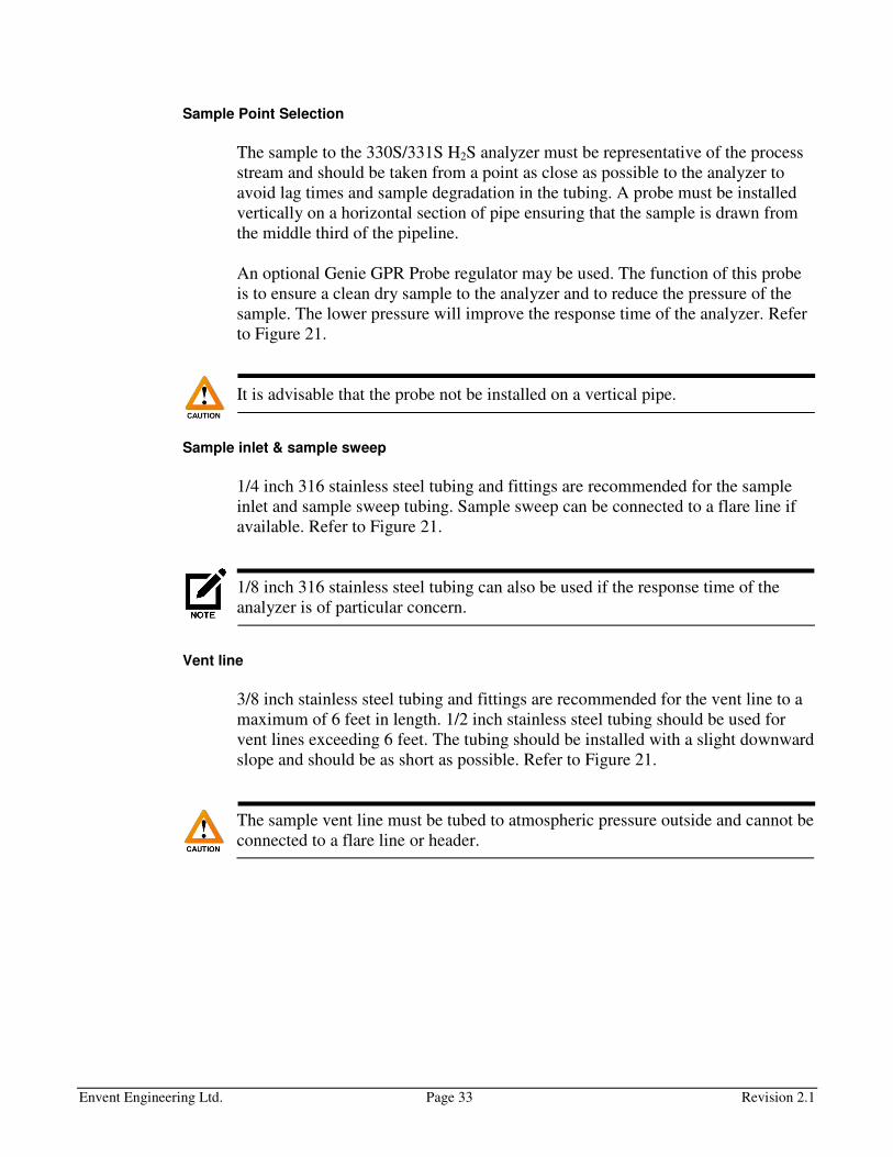
Ethernet Communication Card
The 330S/331S H2S analyzer has the capability to communicate through RS-232
and RS-485. For Ethernet (TCP/IP Protocol), a communication card is
implemented to the analyzer at customer request, refer to Figure 19 .
Figure 19. Ethernet Communication Card

Envent Engineering Ltd. Page 31 Revision 2.1
INSTALLATION
Installation Requirements
Electrical Requirements
The 330S/331S H2S analyzer's controller board can either be 110-240VAC or 10-
32VDC. Consult the analyzer nameplate attached to it or factory calibration
certificate for more information.
Controller board ground connection to chassis is represented by the letters “FG”
and ground symbol.
Certification nameplate shows the voltage range at which the controller board can
withstand (e.g., 120 – 240 VAC), however, when using external devices which
are powered by the controller board (e.g., solenoids), that voltage range no longer
applies and only the external device’s voltage rating shall be used; e.g., 120 VAC
rated solenoid, the analyzer shall be powered with only 120 VAC and not 240
VAC.
The power consumption for a VDC analyzer is 3 Watts and for a VAC is 5 Watts.
For the total sulfur option the power consumption 300 Watts.
Location for the System
First to be considered is the electrical area classification the analyzer will be
installed in. Make sure the analyzer meets the requirements for the installation
site. The 330S H2S analyzer is suitable for Class I, Division 1 Groups CD (or
Groups BCD by customer request). The 331S H2S analyzer is suitable for Class I,
Division 2 Groups ABCD.
When the total sulfur option is used, the 330S is rated for Class I, Division 1
Groups BCD and the 331S is for Class I, Division 2 Groups BCD.
The 330S/331S H2S analyzer should be mounted in an area in which it is not
exposed to vibration, excessive pressure, temperature and/or environmental
variations. The ambient temperature range for the 330S/331S H2S analyzers is 0
to 50 Degree Celsius. If the analyzer is installed in an area where temperatures go
out of this range or it varies abruptly, Envent Engineering Ltd has options such as
cabinets or shelters; consult Envent Engineering Ltd.

Envent Engineering Ltd. Page 32 Revision 2.1
Space Requirements
Figure 20. Space Requirements for the 330S & 331S H2S Analyzers
Make sure to leave at least 1 feet of extra space on the left side of the 330S H2S
analyzer. This will allow proper opening of the side door located at the upper blue
chassis where the H2S sensing tape is located.
Envent Engineering Ltd. Page 33 Revision 2.1
Sample Point Selection
The sample to the 330S/331S H2S analyzer must be representative of the process
stream and should be taken from a point as close as possible to the analyzer to
avoid lag times and sample degradation in the tubing. A probe must be installed
vertically on a horizontal section of pipe ensuring that the sample is drawn from
the middle third of the pipeline.
An optional Genie GPR Probe regulator may be used. The function of this probe
is to ensure a clean dry sample to the analyzer and to reduce the pressure of the
sample. The lower pressure will improve the response time of the analyzer. Refer
to Figure 21.
It is advisable that the probe not be installed on a vertical pipe.
Sample inlet & sample sweep
1/4 inch 316 stainless steel tubing and fittings are recommended for the sample
inlet and sample sweep tubing. Sample sweep can be connected to a flare line if
available. Refer to Figure 21.
1/8 inch 316 stainless steel tubing can also be used if the response time of the
analyzer is of particular concern.
Vent line
3/8 inch stainless steel tubing and fittings are recommended for the vent line to a
maximum of 6 feet in length. 1/2 inch stainless steel tubing should be used for
vent lines exceeding 6 feet. The tubing should be installed with a slight downward
slope and should be as short as possible. Refer to Figure 21.
The sample vent line must be tubed to atmospheric pressure outside and cannot be
connected to a flare line or header.

Envent Engineering Ltd. Page 34 Revision 2.1
Figure 21. 331S Recommended Venting for 331S (Same as the 330S H2S Analyzer)
Sample Volume & Flow Rate
The sample should be supplied to the 330S/331S H2S analyzer at 10-15 psig and
at a flow of 83.63 cc/min (set flowmeter at 2.0). A bypass sweep is recommended
to reduce sample lag time in the sample line if it is at high pressure or it is longer
than 15 feet (The Standard H2S conditioning sample system has a bypass sweep).
The standard sample tubing material is 1/4" 316 stainless steel; however, 1/8"
stainless steel tubing can be used if the response time is critical (refer to Table 3).
Tube
Size
(")
Tube
Gauge
ID (") ID (cm) Flow
(SCFH)
Flow
Std.
(cc/min)
Pressure
(PSIA)
Lag
Time per
100' (min)
Lag
Time per
100' (sec)
3/8 20 0.319 0.810 5 2359 800 36.30 2178
3/8 20 0.319 0.810 5 2359 200 9.07 544
3/8 20 0.319 0.810 5 2359 50 2.27 136
1/4 20 0.181 0.459 5 2359 800 11.69 701
1/4 20 0.181 0.459 5 2359 200 2.92 175
1/4 20 0.181 0.459 5 2359 50 0.73 44
1/8 20 0.081 0.205 5 2359 800 2.34 140
1/8 20 0.081 0.205 5 2359 200 0.59 35
1/8 20 0.081 0.205 5 2359 50 0.15 9
Table 3. Sample Volume and & Flow Rate
Carbon steel sample line and/or fittings are not acceptable.

Envent Engineering Ltd. Page 35 Revision 2.1
Receiving the Analyzer
Inspect the packaging for external damage right after is received. If there is any
physical damage, please contact Envent Engineering Ltd and request that the
carrier's agent be present when the analyzer is unpacked. If a disagreement arises
the incoterms agreed by the seller and the customer will overrule any dispute.
Unpacking the Analyzer
If damage is found in the shipping container see previous section "Receiving the
Analyzer".
1. Open the shipping container and remove the foam packing or other packing
materials from the shipping box.
2. Take out the analyzer and the start-up kit.
The 330S H2S analyzer with a standard Sample conditioning system weights
approximately 105 lb. Unpacking and transporting requires a minimum of two
persons.
3. Make sure the start-up kit is complete (refer to list below). For some special
and more complex analyzers, there might be extra parts in the start-up kit.
Standard spare parts for 330S H2S analyzers:
1. 330S Customer Binder
• Customer Manual(s) and Addendums
• Factory Calibration Certificate
• Factory Configuration
• Drawing Package
• Cal Gas Certificate(s)
2. USB flash drive (containing all documentation)
3. 300' H2S Sensing Tape. Part No. 330133XS
4. 1 Liter Analyzer Fluid. Part No. 330129
5. Funnel
6. 330S Serial Comm. External Cable (USB to Mini USB). Part No. 600002
7. Humidifier (uninstalled). Part No. 330061 (Part No. 330061D for SDS)
8. Bolts For explosion proof enclosure (x22)

Envent Engineering Ltd. Page 36 Revision 2.1
Standard spare parts for 331S H2S analyzers:
1. 331S Customer Binder
• Customer Manual(s)
• Factory Calibration Certificate
• Factory Configuration
• Drawing Package
• Cal Gas Certificate(s)
2. USB flash drive (containing all documentation)
3. 300' H2S Sensing Tape. Part No. 330133XS
4. 1 Liter Analyzer Fluid. Part No. 330129
5. Funnel
6. 331S Serial Comm. External Cable (USB to Mini USB). Part No. 600002
7. Humidifier (uninstalled). Part No. 330061 (Part No. 330061D for SDS)
Installation procedure & Start-up
The following steps should be followed for proper installation and start-up of the
analyzer.
1. Unpack the analyzer and check for damage. Refer to "Receiving the
Analyzer" on page 35 for more information.
2. Ensure the analyzer power supply and range are suitable for the installation
location. Refer to "Electrical Requirements" on page 31 for more information.
3. Check that the hazardous location rating is suitable for the installation
location. Refer to "Location for the System" on page 31 for more information.
4. Ensure that the selected installation site provides adequate room for
maintenance and repair. Refer to "Space Requirements" on page 32 for more
information.
5. Select an installation location close to the sample point. Refer to "Sample
Point Selection", "Sample inlet & sample sweep", and "Vent line" sections on
page 33.
6. Bolt the analyzer to the wall with the H2S sensing tape drive at approximately
eye level.
7. Wire the power, analog outputs and discrete outputs from the analyzer.
Envent Engineering Ltd. Page 37 Revision 2.1
8. Tube the Sample inlet, sample sweep, and sample vent lines from the
analyzer.
9. Ensure there is enough H2S Sensing tape. To install H2S sensing tape refer to
"H2S Sensing Tape Change Procedure" on page 57.
10. Install the Humidifier, if applicable. Ensure there is enough 5% acetic acid or
distilled water in the humidifier. Refer to "Humidifier Unit" on page 22 for
more information
11. Apply power to the analyzer. The display will illuminate and the H2S sensing
tape will advance for a few seconds.
12. Press the menu button until mV is displayed. Check that the mV reading is
1000 mV (± 100 mV).
There are two mV values shown in the display, the "mV Zero" and the "mV"
Values. Check for the "mV" Values.
For the SDS models, check for "Sensor 1 mV" and "Sensor 2 mV".
13. Make sure the sample inlet valve, sample sweep valve, and pressure regulator
are completely closed. The pressure regulator is completely closed when the
knob handle is counter clock wise.
14. Turn on the sample gas flow to the conditioning sample system and then open
the sample inlet valve.
15. Open the sweep valve slightly and adjust pressure regulator to 15 psig and the
flow meter to 2.0.
16. Allow twenty minutes for the analyzer to stabilize. The analyzer calibration
can be verified if calibration gas is available, refer to "H2S Gas Calibration"
on page 54. If no calibration gas is available, the analyzer may be operated
using the factory calibration settings until calibration gas is available.
Envent Engineering Ltd. Page 38 Revision 2.1
OPERATION & CONFIGURATION
The 330S/331S H2S analyzer can be configured by using the display-button
function or by connecting the analyzer to a computer through USB.
Analyzer Display Interface
By using the analyzer's display, the user can only view and/or change certain
parameters set at the factory. For advance changes refer to "Analyzer ICE
Software Interface" on page 39. The display is made up of a Graphic Display, four
(4) push-buttons and (8) LED's. Refer to Figure 22.
Figure 22. 330S Display (left) & 331S Display (right)
The Descriptions and Function of the display buttons and LED's are described in
table Table 4 & Table 5.
Button Description/Function
Bypass Used to inhibit all analyzer alarms to a non-alarm state and
sets the analog 4-40 mA output to 2 mA. The Bypass LED
illuminates when Bypass mode is enabled.
Scroll Right [→] Used to move the cursor to the right. Also used to SAVE
configuration adjustments when moved all the way to the
right of the screen.
Scroll Left [←] Used to move the cursor to the left. Also used to CANCEL
configuration adjustments when moved all the way to the left
of the screen.
Menu/Set Used to cycle through the menu options. Also used to
increase numerical values when making configuration
adjustments.
Table 4. Display Button Description/Function
Envent Engineering Ltd. Page 39 Revision 2.1
LED Description/Function
Bypass Illuminates when the analyzer is in bypass mode.
LED A & B Red LEDs that can be used for different alarm
configurations. By default, these LEDs are left as spare.
Fault Illuminates when there is a fault in the Analyzer. Fault is
used for Board temperature, Sensor High/Low, Low H2S
sensing tape sensor, Pressure switch, etc.
LED 1 to 4 Green LEDs that can be used for different alarms or
conditions. By default, H alarm activates LED-1 and HH
alarm activates LED-2. (Refer to the LED Sticker on the
analyzer door on the inside (331S) or to the right side of the
blue chassis on of the XP enclosure).
Table 5. Display LED Description/Function
Analyzer ICE Software Interface
Introduction to the 330S/331S ICE Software
The 330S/331S H2S analyzer has a software application for more advanced
changes on the analyzer's configuration. To install the ICE Software, refer to the
installer which comes in a USB flash drive with the analyzer (Check Start-up kit
box). It is also available at www.envent-eng.com.
The analyzer is configured at the factory according to the information provided by
the customer at the time of purchase. If no information is provided by the
customer, Envent Engineering Ltd will assign a standard configuration.
This manual covers only information that will help the user update/change the
analyzer's configuration file. The features in the ICE Software that are not
covered on this manual are not to be changed from its factory configuration. If
advanced changes are necessary involving features not cover on this manual,
contact Envent Engineering Ltd for assistance.
Envent Engineering Ltd. Page 40 Revision 2.1
Safety Guidelines
Read this manual section before operating the ICE software to change the default
configuration to ensure correct operation of the analyzer.
Envent Engineering Ltd configures analyzer in conformance to the customer
specifications (if applicable). Any modifications on the factory configuration by
the user may impair the proper functionality of the analyzer if not performed
properly. Contact Envent Engineering Ltd for more information on how to modify
the configuration of the analyzer.
For Class I, Division 1 Model 330S Analyzers, the glass window must remain
installed in order to maintain area classification. However, to communicate to the
330S analyzer via RS-232 or RS-485 the glass window must be removed. Ensure
area is known to be a non-hazardous before removing the explosion proof
window.
Using the ICE Software
This section covers an overview on the 330S/331S ICE Software application. It
shows how to connect, configure and change the factory configuration to
accommodate for different applications.
The H2S analyzer's controller board has a USB port for local user interface and
three RS-485 connections. The RS-485 connections are identified with numbers
from 1 to 3 on the controller board. Connections RS-232, RS-485-1 and RS-485-2
are used to communicate with the analyzer to check or modify the current
analyzer's configuration; these connections have Modbus communication
capabilities. RS-485-3 is only used for remote display option. The proper Mini
USB to USB cable is provided in the analyzer spare parts.
Connecting the Analyzer to a Computer Using the ICE Software
Install the ICE software on your computer using the software installer provided in
the USB flash drive or on the Envent Engineering's website.
Once the ICE software is installed, physically connect the analyzer to the
computer using the Mini USB to USB cable provided.
Open the ICE software. Select the USB port the analyzer is physically connected
to. Do not select ''Enable Hi-Speed''. Click on ''Read'' and wait until the green bar
has completed at the bottom of the screen, refer to Figure 23.
Once communication has been established successfully, the user will be able to
modify the analyzer's configuration and write it to the analyzer.

Envent Engineering Ltd. Page 41 Revision 2.1
Figure 23. ICE Software: Enable Communication
If there are communication problems, check for the following:
1. Check that the analyzer is ON.
2. Check that the communication cable is properly connected.
3. If the ICE software application was open before physically connecting the
analyzer to the computer, close the ICE software and re-open it. Try again and
enable communication.
Modify analyzer's Configuration
Before modifying the factory configuration file, make sure to save it on your
computer first for future retrieval. If the factory configuration file is lost or
modified without saving it, a copy is kept in the USB flash drive given with the
analyzer. Envent Engineering Ltd can also provide a copy. To save the
configuration file, go to File > Save or Save as.
Make the appropriate changes on the factory configuration file through the ICE
software. When changes are made, they need to be uploaded to the analyzer in
order to overwrite what is currently on it. Click on the ''Write button'' (located
beside the Read button; refer to Figure 23) and wait until the new configuration is
uploaded successfully.
Discrete Input Configuration
In this section of the ICE software, discrete inputs (and virtual inputs) are
configured. Go to System IO>Inputs>Discrete Inputs. Refer to Figure 24.

Envent Engineering Ltd. Page 42 Revision 2.1
Analog Inputs are not covered in this manual since they must not be changed from
their factory values.
Figure 24. ICE Software: Configuration: System IO Tab: Inputs Tab
IO Name
IO names are names assigned to the discrete and virtual inputs. The name is up to
the user's discretion. Figure 24 shows DI#1 to be for Low H2S Tape Sensor. Once
a discrete or virtual input is configured, an alarm can be added based on the
discrete or virtual input status. Refer to "Alarm Configuration" on page 45.
Active State Action
Active state action is the response or output the discrete or virtual input will have
when changing states. "Standard" is selected when the discrete or virtual input is
used to output an alarm condition. "Bypass and halt" will place the analyzer into
these states when the discrete or virtual input changes state. "Acknowledge" is
used when an latched alarm needs to be acknowledged remotely (by means of a
switch).
Analog & Discrete Output Configuration
In this section of the ICE software, analog and discrete outputs are configured. To
access the analog and discrete outputs, go to System IO>Output Tab. Refer to
Figure 25.
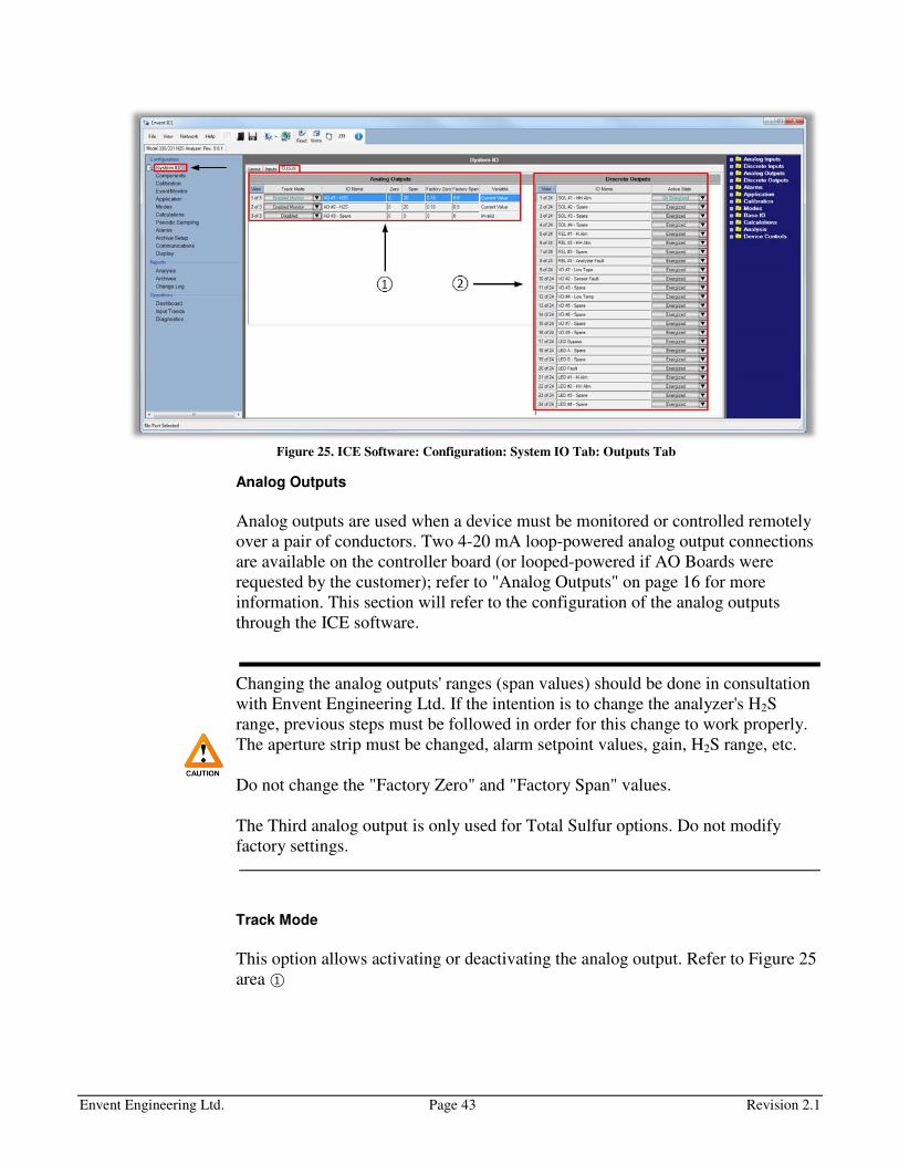
Envent Engineering Ltd. Page 43 Revision 2.1
Figure 25. ICE Software: Configuration: System IO Tab: Outputs Tab
Analog Outputs
Analog outputs are used when a device must be monitored or controlled remotely
over a pair of conductors. Two 4-20 mA loop-powered analog output connections
are available on the controller board (or looped-powered if AO Boards were
requested by the customer); refer to "Analog Outputs" on page 16 for more
information. This section will refer to the configuration of the analog outputs
through the ICE software.
Changing the analog outputs' ranges (span values) should be done in consultation
with Envent Engineering Ltd. If the intention is to change the analyzer's H2S
range, previous steps must be followed in order for this change to work properly.
The aperture strip must be changed, alarm setpoint values, gain, H2S range, etc.
Do not change the "Factory Zero" and "Factory Span" values.
The Third analog output is only used for Total Sulfur options. Do not modify
factory settings.
Track Mode
This option allows activating or deactivating the analog output. Refer to Figure 25
area ①

Envent Engineering Ltd. Page 44 Revision 2.1
IO Name
IO Names are names assigned to the analog outputs. The name is up to the user's
discretion. Figure 25 area ① shows the analog output names as "H2S" as default
for standard configurations.
Zero & Span
These columns refer to the range being measured. Since the variables used for the
analog outputs are the analyzer H2S readings, the zero and span values are 0 to 20
ppm of H2S (for standard configurations). Refer to Refer to Figure 25 area ①
For the standard factory configuration on 330S/331S, both 1 and 2 analog output
variables are based on the analyzer H2S readings of sample 1.
For the standard factory configuration on the 330SDS/331SDS models, analog
output 1 variable is based on H2S reading of sample 1 and analog output 2 variable
is based on H2S reading of sample 2.
Factory Zero & Factory Span
These values are set at factory. They compensate for the differences on the
resistors and capacitors in the controller board. Do not modify these values.
Variable
Items used by the analog output to signal their current statuses. To select a new
variable, go to the right hand menu on dark blue background and find the new
variable. Click and drag the variable to the variable column and proceed to change
the specification on the analog output row according to the new variable.
Discrete Outputs
In this section of the ICE software, discrete outputs are named and their status
states are set-up. Refer to Refer to Figure 25 area ②.
IO Name
IO Names are names assigned to the discrete outputs. The name is up to the user's
discretion. Names are set-up according to the analyzer standard factory
configuration file. These names are based on what alarm variable they are used
for. These discrete output names will appear in the Output Controls column in the
Alarm tab section. Refer to Figure 25 area ②.

Envent Engineering Ltd. Page 45 Revision 2.1
Active State
Active state is the condition the discrete output will have when in alarm. If
selected as "De-energized", the discrete output will be fail-safe. Refer to Figure 25
area ②.
Alarm Configuration
In this section of the ICE software, alarms and alarm setpoint are configured.
Refer to this section to learn how to add, modify, or delete an alarm.
Adding an Alarm
Go into the ''Alarm'' tag, refer to Figure 26. This section will show the current
alarm configuration on the analyzer.
Figure 26. ICE Software: Configuration: Alarms Tab
To add an alarm, use the right hand menu on dark blue background to locate the
appropriate variable as shown in Figure 26. On the right hand menu is where all
analyzer variables can be found. In this example, we will add an Emergency
System-Shutdown (ESD) using 15 ppm of H2S concentration readings as the
setpoint. To add the appropriate variable for this example, click on
Modes>Sample> H2S >Current Value. Refer to Figure 27.
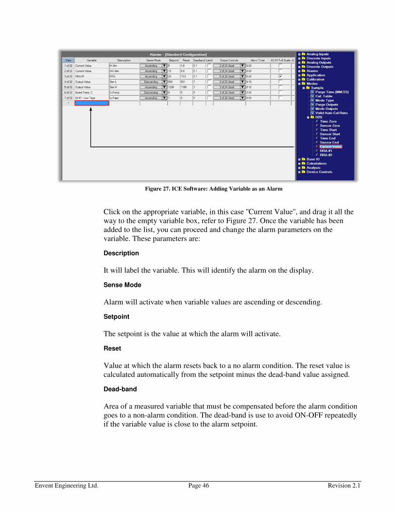
Envent Engineering Ltd. Page 46 Revision 2.1
Figure 27. ICE Software: Adding Variable as an Alarm
Click on the appropriate variable, in this case ''Current Value'', and drag it all the
way to the empty variable box, refer to Figure 27. Once the variable has been
added to the list, you can proceed and change the alarm parameters on the
variable. These parameters are:
Description
It will label the variable. This will identify the alarm on the display.
Sense Mode
Alarm will activate when variable values are ascending or descending.
Setpoint
The setpoint is the value at which the alarm will activate.
Reset
Value at which the alarm resets back to a no alarm condition. The reset value is
calculated automatically from the setpoint minus the dead-band value assigned.
Dead-band
Area of a measured variable that must be compensated before the alarm condition
goes to a non-alarm condition. The dead-band is use to avoid ON-OFF repeatedly
if the variable value is close to the alarm setpoint.
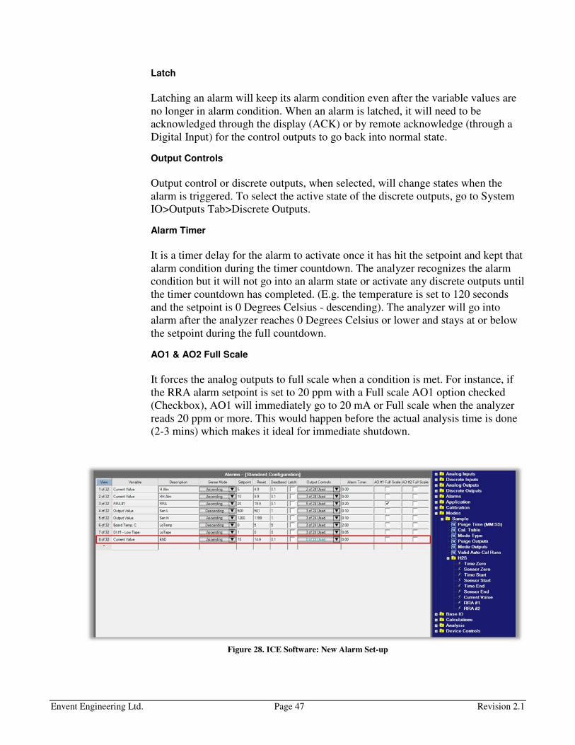
Envent Engineering Ltd. Page 47 Revision 2.1
Latch
Latching an alarm will keep its alarm condition even after the variable values are
no longer in alarm condition. When an alarm is latched, it will need to be
acknowledged through the display (ACK) or by remote acknowledge (through a
Digital Input) for the control outputs to go back into normal state.
Output Controls
Output control or discrete outputs, when selected, will change states when the
alarm is triggered. To select the active state of the discrete outputs, go to System
IO>Outputs Tab>Discrete Outputs.
Alarm Timer
It is a timer delay for the alarm to activate once it has hit the setpoint and kept that
alarm condition during the timer countdown. The analyzer recognizes the alarm
condition but it will not go into an alarm state or activate any discrete outputs until
the timer countdown has completed. (E.g. the temperature is set to 120 seconds
and the setpoint is 0 Degrees Celsius - descending). The analyzer will go into
alarm after the analyzer reaches 0 Degrees Celsius or lower and stays at or below
the setpoint during the full countdown.
AO1 & AO2 Full Scale
It forces the analog outputs to full scale when a condition is met. For instance, if
the RRA alarm setpoint is set to 20 ppm with a Full scale AO1 option checked
(Checkbox), AO1 will immediately go to 20 mA or Full scale when the analyzer
reads 20 ppm or more. This would happen before the actual analysis time is done
(2-3 mins) which makes it ideal for immediate shutdown.
Figure 28. ICE Software: New Alarm Set-up

Envent Engineering Ltd. Page 48 Revision 2.1
Figure 28, shows a new alarm non-latching, ascending, setpoint of 15 ppm, dead-
band of 0.1, description as ESD, no output controls and no alarm timer.
To move the alarm up or down on the list, click on the ''View'' column for that
specific alarm. In our example, click on the ''8 of 32'' box which highlights the
entire alarm row. Then press control + up or down arrow keys.
Removing an Alarm
Click on the ''View'' column for that specific alarm. Once the alarm row is
highlighted, press ''Delete'' on the keyboard.
Archive Setup Configuration
In this section of the ICE software, archiving is configured. To set up the
archiving to record information on certain variables, go to the Configuration >
Archive Setup Tab in the left side menu.
Figure 29. ICE Software: Configuration: Archive Setup Tab
The green-black box shown in Figure 29 is a representation of the memory
capacity of the controller board for archiving information. The green area
represents the memory that will be consumed or used by the items already selected
and the amount (in this case 100,000 records). The black area represents the
memory availability. Figure 29 shows that the two items or variable selected (in
Envent Engineering Ltd. Page 49 Revision 2.1
this case Current Value and Sensor Zero) with 100,000 records (per item) would
use 54.6% of the total memory capacity.
Item & Archive Name
There are up to 6 groups with a maximum of 6 items (variables) that can be added
to each group. Group 1 name assigned for Figure 29 is "Sample".
Rollover Count
It is the number of records per item that the analyzer will archive.
Activation: End of Analysis
The analyzer obtains a new H2S reading after the analysis cycle is completed (360
sec max). That is when the analyzer will record the values of each item selected.
The average analysis time is 140 sec to 220 sec; depends on the application and
the H2S range.
Activation: Continuous (Always Set)
When data needs to be recorded at a certain time interval regardless of the analysis
cycle, this option is used. The time interval options vary from every 1 sec to every
30 min. The End of Analysis and the Continuous (Always Set) options can also be
selected at the same time.
Selecting More Items (Variables) Inside a Group
To select items inside a group, locate the variables in the right hand menu on dark
blue background and drag them into the ''Item'' column; same procedure as
"Adding an Alarm" on page 45.
Creating another Group
To create a new group, simply select an item in the right hand menu on dark blue
background and drag it into an empty row in the ''Item'' column. Assign a name,
the maximum amount of records and the activation method.
Retrieve Archives from the Analyzer
Go to the ''Archive'' tab under the report section in the left hand menu. Refer to
Figure 30.
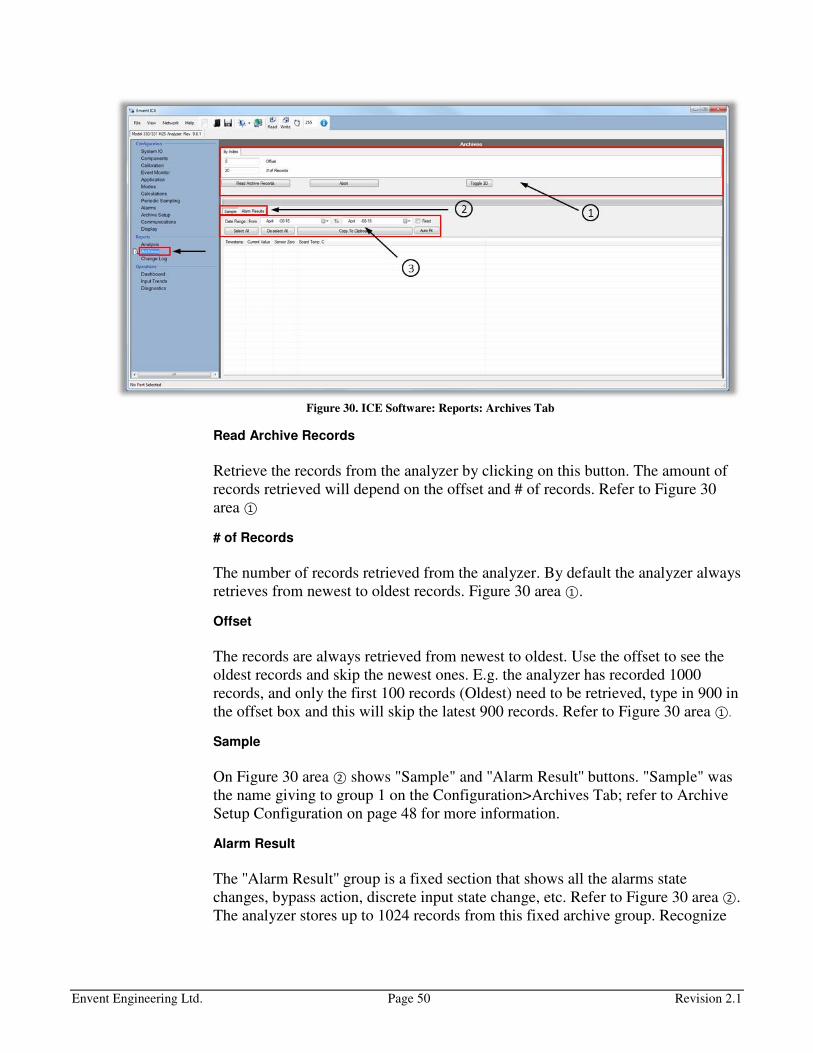
Envent Engineering Ltd. Page 50 Revision 2.1
Figure 30. ICE Software: Reports: Archives Tab
Read Archive Records
Retrieve the records from the analyzer by clicking on this button. The amount of
records retrieved will depend on the offset and # of records. Refer to Figure 30
area ①
# of Records
The number of records retrieved from the analyzer. By default the analyzer always
retrieves from newest to oldest records. Figure 30 area ①.
Offset
The records are always retrieved from newest to oldest. Use the offset to see the
oldest records and skip the newest ones. E.g. the analyzer has recorded 1000
records, and only the first 100 records (Oldest) need to be retrieved, type in 900 in
the offset box and this will skip the latest 900 records. Refer to Figure 30 area ①.
Sample
On Figure 30 area ② shows "Sample" and ''Alarm Result'' buttons. "Sample" was
the name giving to group 1 on the Configuration>Archives Tab; refer to Archive
Setup Configuration on page 48 for more information.
Alarm Result
The ''Alarm Result'' group is a fixed section that shows all the alarms state
changes, bypass action, discrete input state change, etc. Refer to Figure 30 area ②.
The analyzer stores up to 1024 records from this fixed archive group. Recognize

Envent Engineering Ltd. Page 51 Revision 2.1
that these records are only saved when there is a state change. It is not based on a
time frame or analysis time.
Date Range
The Date Range is the option of retrieving data from specific calendar days. By
default, the analyzer will always retrieve data from the current date. To always
retrieve records from a specific Date Range, check the “Fixed” box to retrieve
records from a specific time. Refer to Figure 30 area ③.
Select/De-select All, Copy to Clipboard, & Auto Fit
Once archives have been retrieved from the analyzer, click on Select all and then
click on Copy to clipboard. This data can then be used in a spreadsheet document.
The auto fit option is used to increase the column's width for when the variable's
name being recorded is too long. Refer to Figure 30 area ③.
Display Configuration
To configure or change the factory configuration on the display, go to the
''Display'' tab on the left hand menu. Figure 31 area ① shows the current variables
that appear in the analyzer display. Area ② shows different options for the LED's,
display options, and button options. Area ③ is used for adding special characters
into the caption and units areas.
Figure 31. ICE Software: Configuration: Display Tab
Envent Engineering Ltd. Page 52 Revision 2.1
Caption
Names assigned to the selected variables to be shown in the display. The name is
up to the user's discretion
Variable
Item that will be shown in the analyzer's display. To select a new variable, go to
the right hand menu on dark blue background and find the new variable. Click and
drag variable to the variable box and proceed to change the specification on the
analog output row according to the new variable.
Units
Unis are a simple multiple of the unit of measurement that describes the variable
selected. Refer to Figure 31 area ①.
Decimals
This is where the amount of decimals per variable are decided. Refer to Figure 31
area ①. For lower range H2S analyzers (e.g. 0-20 ppm) it is recommended to use 1
to 2 decimal points, but for high range (e.g. 0-10,000 ppm) it is recommended to
not use decimal points as they are not significant enough for these ranges.
LED Blink Hz
This option is used to make the LED blink when activated. The lower the value,
the fastest it will blink. Zero value means no blinking. Refer to Figure 31 area ②.
Backlit Timeout (Seconds)
Amount of seconds the display backlit will stay ON after pressing a display
button. Zero means the backlit stays always ON. Refer to Figure 31 area ②.
Menu Timeout (Seconds)
The amount of seconds the display will wait until it automatically returns to the
main menu. Zero means the display will not return to the main menu
automatically. The user will need to complete the menu cycle (by pressing the
menu button – lower button) until it goes back to the main menu. Refer to Figure
31 area ②.
Envent Engineering Ltd. Page 53 Revision 2.1
Layout Type
This applies to the main menu in the analyzer display. The user can select from 1
to 4 items. These items refer to the variables selected in Figure 31 area ①. If "2
lines" is selected, the 1st and 2
nd variables will appear in the main menu.
The display text size will change accordingly to the number of lines displayed in
the main menu.
Top Button Function
This feature allows the user to change the function of the top button in the
analyzer display. By default, this button is set to be the bypass manual option.
The other options are: Halt, Acknowledge, and Disable.
Keep in mind that the acknowledge option is already included in the display
variables.
Remote Display
This option allows having a remote display which it would be connected to the
RS-485-3 on the controller board.

Envent Engineering Ltd. Page 54 Revision 2.1
CALIBRATION PROCEDURES
H2S Gas Calibration
Depending on the application, the 330S/331S H2S analyzer will require more
or fewer periodic calibrations. There is no specific time as to how often the
H2S analyzer should be calibrated. It will depend on the application,
importance of accuracy for the application, and how dirty or clean the
environment and sample are. The following is the calibration procedure for
the 330S/331S H2S analyzer:
1. Source a calibration gas of H2S in balance of N2 regulated to 15 psi
(check expiry date). H2S concentration to be approximately 2/3 of full
scale range or close to the H2S alarm set point.
2. Press the bypass button and verify the "Bypass" LED illuminates (alarms
will be held in the non- alarm state).
3. Turn off all gas supplies to the analyzer and check that a sufficient
amount of H2S sensing tape is installed.
4. Press the "Menu/Set" button until "Mtr Run" is displayed. Press the right
arrow [→], the H2S sensing tape will advance for approximately 10
seconds.
5. Press the "Menu/Set" button until "mV" is displayed ("###mV"). If the
mV reading is 1000mV (+100mV), proceed to the next step, otherwise
re-zero sensor (Refer to "Re-zero Sensor Procedure" on page 55).
6. Connect calibration gas to calibration port and turn the 3-way calibration
valve 180°. The valve handle should be pointing towards where the gas
bottle tubing is connected to (Calibration Inlet).
7. Turn on sample inlet valve, ensure that the sample regulator is supplying
15psig to the eductor (make sure there is suction from the eductor block).
Adjust the flow meter to 2.0. Wait until the H2S reading has stabilized
(10 to 15 minutes).
8. With calibration gas applied, if H2S reading is satisfactory (+2% of
analyzer full range) skip to step 16, if H2S reading is not satisfactory a
gain adjustment is required, continue to step 9.
9. Press the "Menu/Set" button until the gain setting is displayed ("###
Gain").
10. Calculate the new gain. New gain value should be within approximately
25% of the gain installed at the factory.

Envent Engineering Ltd. Page 55 Revision 2.1
11. To adjust the gain setting such that the analyzer displays the correct H2S
concentration, press the right [→] and / or left [←] arrows until the cursor
is underneath the number you wish to change.
12. Adjust the number using the "Menu/Set" button (it will increase until "9"
then will cycle back through "0").
13. Save the new gain value by pressing the right arrow [→] until "Saved"
appears or discard by pressing the left [←] arrow until "Cancel" appears.
14. Allow the analyzer to complete two cycles using the new gain value. The
H2S reading should match the calibration gas concentration. Repeat step
10 if necessary.
15. Return to sample gas flow using the 3-way calibration valve.
16. Set the sample gas pressure to 15 psig and set the flow meter to 2.0.
17. Disconnect the calibration gas supply.
18. After waiting 10 to 15 minutes confirm the analyzer reads below the H2S
alarm set points.
Remove the analyzer from bypass mode by pressing the bypass button.
Verify the "Bypass" LED turns off.
Alarms are armed after removing the bypass mode.
Re-zero Sensor Procedure
1. Press the bypass button and verify that the "Bypass" LED illuminates.
2. Turn off sample gas flow using sample inlet valve.
3. Press the "Menu/Set" button until "Mtr Run" is displayed. Press the right
arrow [→], the H2S sensing tape will advance for approximately 10
seconds.
4. Remove the sensor cover.
5. Press the small pushbutton on the sensor block located on the lower left
side next to the wire connector.
• The sensor block will implement a "re-zero" procedure, indicated by
a lit, red LED.

Envent Engineering Ltd. Page 56 Revision 2.1
• When the "re-zero" procedure is complete the LED light will turn
green.
6. Initiate another motor run (Step 3).
7. Press the "Menu/Set" button until "### mV" is displayed.
• Value should be 1000mV (+100mV)
8. Put on sensor cover.
9. Turn on sample gas flow using sample inlet valve.
10. Set the gas pressure to 15 psig and the flow meter to 2.0.
11. Confirm the analyzer reads below the H2S alarm set points.
12. Remove the analyzer from bypass mode by pressing the bypass button.
Verify the "Bypass" LED turns off.
Alarms are armed after removing the bypass mode.
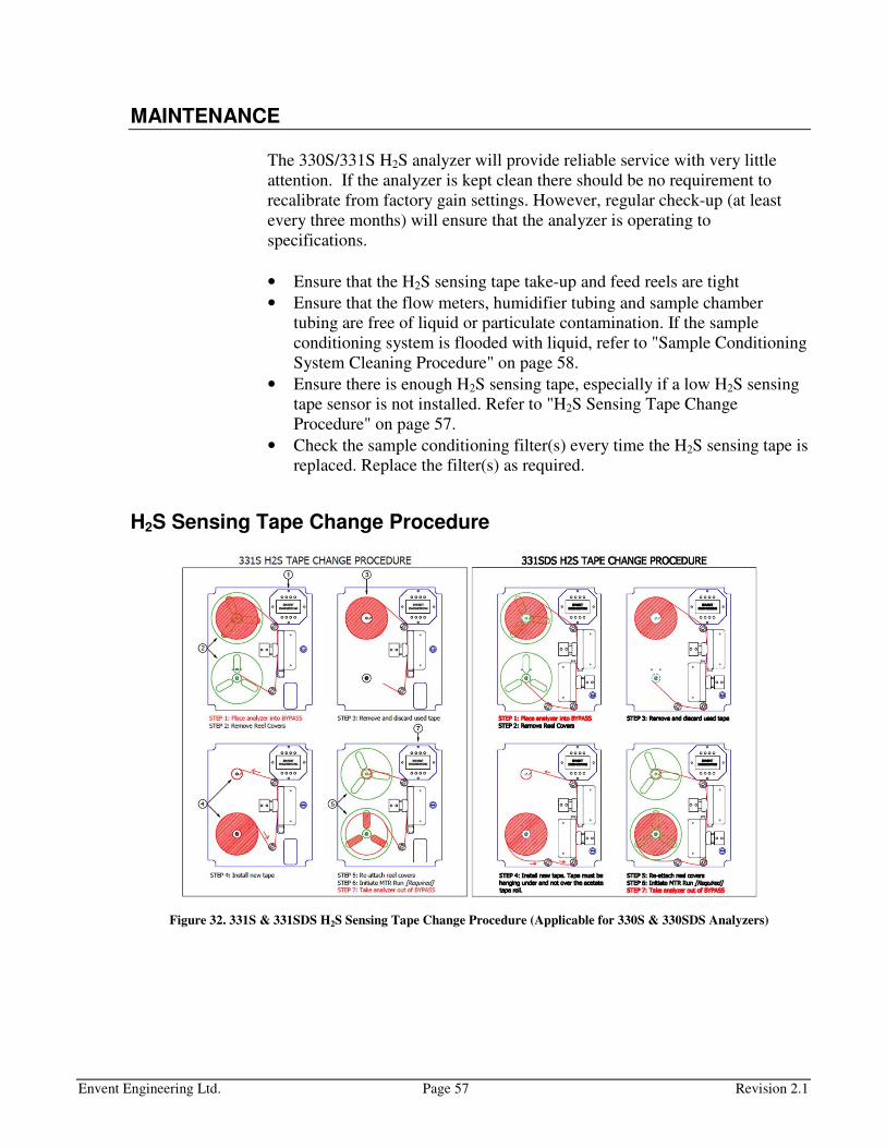
Envent Engineering Ltd. Page 57 Revision 2.1
MAINTENANCE
The 330S/331S H2S analyzer will provide reliable service with very little
attention. If the analyzer is kept clean there should be no requirement to
recalibrate from factory gain settings. However, regular check-up (at least
every three months) will ensure that the analyzer is operating to
specifications.
• Ensure that the H2S sensing tape take-up and feed reels are tight
• Ensure that the flow meters, humidifier tubing and sample chamber
tubing are free of liquid or particulate contamination. If the sample
conditioning system is flooded with liquid, refer to "Sample Conditioning
System Cleaning Procedure" on page 58.
• Ensure there is enough H2S sensing tape, especially if a low H2S sensing
tape sensor is not installed. Refer to "H2S Sensing Tape Change
Procedure" on page 57.
• Check the sample conditioning filter(s) every time the H2S sensing tape is
replaced. Replace the filter(s) as required.
H2S Sensing Tape Change Procedure
Figure 32. 331S & 331SDS H2S Sensing Tape Change Procedure (Applicable for 330S & 330SDS Analyzers)
Envent Engineering Ltd. Page 58 Revision 2.1
Sample Conditioning System Cleaning Procedure
During start-up or plant upset situations, the 330S/331S H2S analyzer may
become contaminated with amine or hydrogen sulfide scavenger solution.
This may cause the analyzer to read low (this can be determined at
calibration). If the analyzer reads low, it will require incremental increases in
the gain to maintain calibration. Please refer to factory calibration sheet for
factory set gain factor. The scavenger solution is water soluble and therefore
is relatively easy to clean.
Material List
Cleaning Kit Part Number: 330900
• Alconox RBS Solid, powdered precision cleaner w/ MSDS (2.5 tbsp)
• 330079 – Rear window and gasket
• MIF-225-PP – Small nipple (x2)
• MIF-32-PVC – Grey nipple
• MIF-32-PP – Big nipple
• MIF-24-PVC – Humidifier replacement tube fittings (x2)
• MIP-4 Humidifier replacement plug
• 06349-40 – Black 1/8" male/female elbow
• LT-2-4 (1/4" x 11") – Tubing for sample chamber to humidifier
• LT-2-4 (1/4" x 10") – Tubing for flow meter to humidifier
• LT-3-5 (3/16" x 10") – Tubing for sample chamber to vent block
• PFA (24") – Tubing for flowmeter to bulkhead
Do not use solvents, brake cleaners, soaps, detergents or rubbing alcohol to
clean up analyzer or sample system.
Procedure
1. Mix a 1% (2-1/2 tbsp per gallon) of Alconox in warm water
2. Sample line tubing
• Shut off flow at the sample point prior to sample conditioning system
• Flush the sample line and components with cleaning solution
• Rinse with fresh water
• Flush with isopropyl alcohol
• Dry with clean, dry instrument air or gas
3. Sample conditioning system – Take pictures of SCS before disassembling
• Remove filter elements from filter housings and discard
• Remove all sample conditioning system components and soak in
cleaning solution

Envent Engineering Ltd. Page 59 Revision 2.1
• Ensure valves are fully open when cleaning
• Flush sample components with fresh water
• Rinse with isopropyl alcohol
• Blow dry with clean compressed air or fuel gas
• If the clear Vinyl tubing appears discolored, replace the tubing.
• Nafion tubing on humidifier should be replaced if it appears
contaminated
Disassembly of the pressure regulator and solenoids in the field is not advised.
Consult the factory if the regulator or solenoid appears contaminated.
4. Re-assemble Stainless Steel Tubing to analyzer according to analyzer
drawing, refer to pictures taken before disassembling or refer to drawing
package.
5. Once sample conditioning system has been re-assembled, apply
calibration gas to the analyzer. Refer to "H2S Gas Calibration" on page 54.

Envent Engineering Ltd. Page 60 Revision 2.1
TROUBLESHOOTING
H2S Readings Issues
Problems Possible Reasons Possible Solutions
Erratic H2S
Readings
Trigger slide and H2S sensing
tape not seated properly
Ensure trigger slide and H2S sensing tape
are seated in the groove of the sample
chamber.
Pressure in building moving up
and down from fan, exhaust or
wind
The eductor should counteract this effect,
however, the eductor may be plugged or
vent blocked. Check there is no blockage
and that all vent tubing and fitting are 316
stainless steel, sized 3/8'' or larger on a
downward slope.
Sample vent/Eductor either
blocked or frozen
Check there is no blockage on the vent
and/or eductor. Check for vacuum in
Eductor block. Vent tubing and fittings
should be 316 stainless steel 3/8'' or larger
on a downward slope. Possible heat trace
required.
Analog input 2 jumper
removed
Re-install jumper in Analog Input across
(+4-20 & -4-20) on the controller board.
Sensor block fault Re-zero sensor block. Refer to "Re-zero
Sensor Procedure" on page 55.
Check for green status led on sensor block
once procedure is done & proper mV on
white H2S sensing tape.
Sensor did not zero on white
H2S sensing tape
Check the H2S Sensing tape, if not properly
installed, refer to "H2S Sensing Tape
Change Procedure" on page 57 or on sticker
in the analyzer's door.
Perform a motor Run: Display>Press Menu
Button until "MTR Run">Press right button.
This will activate the motor and move the
H2S Sensing tape for a few seconds.
Re-zero sensor block if necessary. Refer to
"Re-zero Sensor Procedure" on page 55.
Regulator not maintaining 15
psig (Changing flow rate to
analyzer)
Replace Regulator, Consult Envent
Engineering Ltd.
Continued on next page
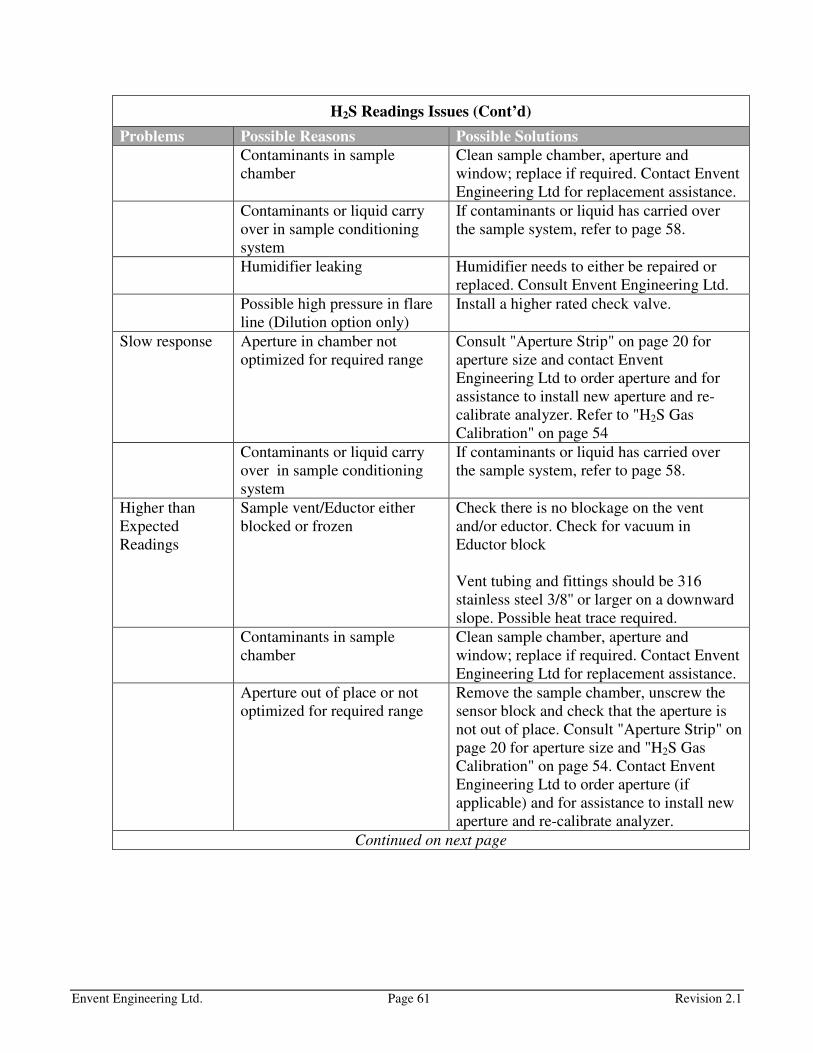
Envent Engineering Ltd. Page 61 Revision 2.1
H2S Readings Issues (Cont’d)
Problems Possible Reasons Possible Solutions
Contaminants in sample
chamber
Clean sample chamber, aperture and
window; replace if required. Contact Envent
Engineering Ltd for replacement assistance.
Contaminants or liquid carry
over in sample conditioning
system
If contaminants or liquid has carried over
the sample system, refer to page 58.
Humidifier leaking Humidifier needs to either be repaired or
replaced. Consult Envent Engineering Ltd.
Possible high pressure in flare
line (Dilution option only)
Install a higher rated check valve.
Slow response Aperture in chamber not
optimized for required range
Consult "Aperture Strip" on page 20 for
aperture size and contact Envent
Engineering Ltd to order aperture and for
assistance to install new aperture and re-
calibrate analyzer. Refer to "H2S Gas
Calibration" on page 54
Contaminants or liquid carry
over in sample conditioning
system
If contaminants or liquid has carried over
the sample system, refer to page 58.
Higher than
Expected
Readings
Sample vent/Eductor either
blocked or frozen
Check there is no blockage on the vent
and/or eductor. Check for vacuum in
Eductor block
Vent tubing and fittings should be 316
stainless steel 3/8'' or larger on a downward
slope. Possible heat trace required.
Contaminants in sample
chamber
Clean sample chamber, aperture and
window; replace if required. Contact Envent
Engineering Ltd for replacement assistance.
Aperture out of place or not
optimized for required range
Remove the sample chamber, unscrew the
sensor block and check that the aperture is
not out of place. Consult "Aperture Strip" on
page 20 for aperture size and "H2S Gas
Calibration" on page 54. Contact Envent
Engineering Ltd to order aperture (if
applicable) and for assistance to install new
aperture and re-calibrate analyzer.
Continued on next page
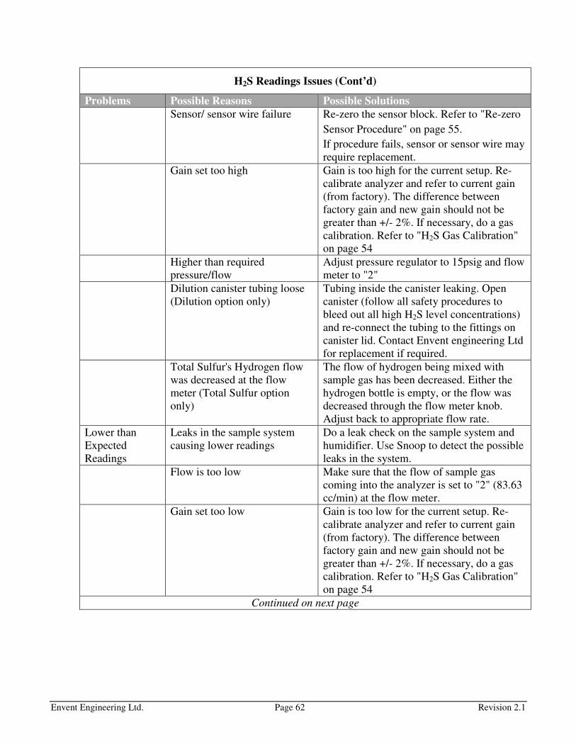
Envent Engineering Ltd. Page 62 Revision 2.1
H2S Readings Issues (Cont’d)
Problems Possible Reasons Possible Solutions
Sensor/ sensor wire failure Re-zero the sensor block. Refer to "Re-zero
Sensor Procedure" on page 55.
If procedure fails, sensor or sensor wire may
require replacement.
Gain set too high Gain is too high for the current setup. Re-
calibrate analyzer and refer to current gain
(from factory). The difference between
factory gain and new gain should not be
greater than +/- 2%. If necessary, do a gas
calibration. Refer to "H2S Gas Calibration"
on page 54
Higher than required
pressure/flow
Adjust pressure regulator to 15psig and flow
meter to "2"
Dilution canister tubing loose
(Dilution option only)
Tubing inside the canister leaking. Open
canister (follow all safety procedures to
bleed out all high H2S level concentrations)
and re-connect the tubing to the fittings on
canister lid. Contact Envent engineering Ltd
for replacement if required.
Total Sulfur's Hydrogen flow
was decreased at the flow
meter (Total Sulfur option
only)
The flow of hydrogen being mixed with
sample gas has been decreased. Either the
hydrogen bottle is empty, or the flow was
decreased through the flow meter knob.
Adjust back to appropriate flow rate.
Lower than
Expected
Readings
Leaks in the sample system
causing lower readings
Do a leak check on the sample system and
humidifier. Use Snoop to detect the possible
leaks in the system.
Flow is too low Make sure that the flow of sample gas
coming into the analyzer is set to "2" (83.63
cc/min) at the flow meter.
Gain set too low Gain is too low for the current setup. Re-
calibrate analyzer and refer to current gain
(from factory). The difference between
factory gain and new gain should not be
greater than +/- 2%. If necessary, do a gas
calibration. Refer to "H2S Gas Calibration"
on page 54
Continued on next page

Envent Engineering Ltd. Page 63 Revision 2.1
H2S Readings Issues (Cont’d)
Problems Possible Reasons Possible Solutions
Not using the humidifier or
humidifier leaking
A humidifier is not necessary if the sample
gas inlet is already humidified. If the sample
gas inlet is dry, a humidifier must be used.
Make sure the humidifier unit is placed and
installed correctly. Please refer to
"Humidifier Unit" on page 22.
Humidifier Leaking: it needs to either be
repaired or replaced. Consult Envent
Engineering Ltd.
Sensor/ sensor wire failure Re-zero the sensor block. Refer to "Re-zero
Sensor Procedure" on page 55.
If procedure fails, sensor or sensor wire may
require replacement.
Dilution Instrument air or
carrier gas flow was increased
(Dilution option only)
If the instrument air or the carrier gas is
increased in flow, the readings will be
lower. Make sure to keep a constant flow
and pressure for the instrument or carrier
gas.
Hydrogen flow has been
increased (Total Sulfur option
only)
Lower the hydrogen flow to the specified on
the flow meter.
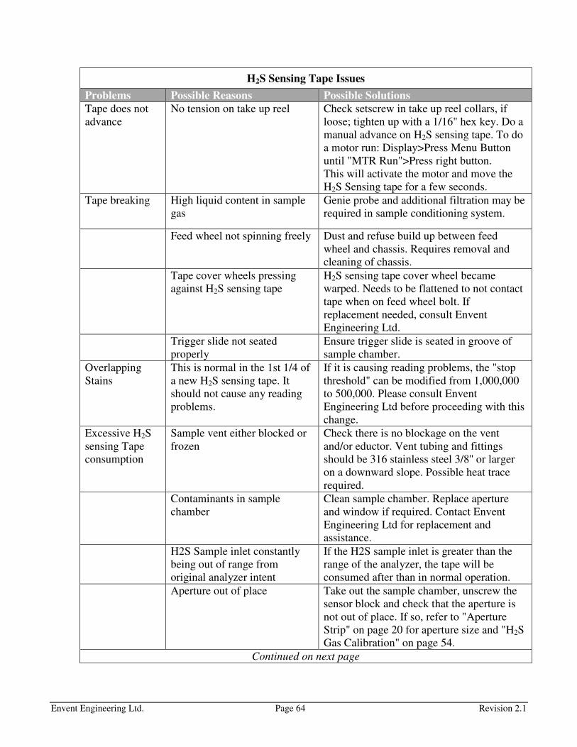
Envent Engineering Ltd. Page 64 Revision 2.1
H2S Sensing Tape Issues
Problems Possible Reasons Possible Solutions
Tape does not
advance
No tension on take up reel Check setscrew in take up reel collars, if
loose; tighten up with a 1/16" hex key. Do a
manual advance on H2S sensing tape. To do
a motor run: Display>Press Menu Button
until "MTR Run">Press right button.
This will activate the motor and move the
H2S Sensing tape for a few seconds.
Tape breaking High liquid content in sample
gas
Genie probe and additional filtration may be
required in sample conditioning system.
Feed wheel not spinning freely Dust and refuse build up between feed
wheel and chassis. Requires removal and
cleaning of chassis.
Tape cover wheels pressing
against H2S sensing tape
H2S sensing tape cover wheel became
warped. Needs to be flattened to not contact
tape when on feed wheel bolt. If
replacement needed, consult Envent
Engineering Ltd.
Trigger slide not seated
properly
Ensure trigger slide is seated in groove of
sample chamber.
Overlapping
Stains
This is normal in the 1st 1/4 of
a new H2S sensing tape. It
should not cause any reading
problems.
If it is causing reading problems, the "stop
threshold" can be modified from 1,000,000
to 500,000. Please consult Envent
Engineering Ltd before proceeding with this
change.
Excessive H2S
sensing Tape
consumption
Sample vent either blocked or
frozen
Check there is no blockage on the vent
and/or eductor. Vent tubing and fittings
should be 316 stainless steel 3/8'' or larger
on a downward slope. Possible heat trace
required.
Contaminants in sample
chamber
Clean sample chamber. Replace aperture
and window if required. Contact Envent
Engineering Ltd for replacement and
assistance.
H2S Sample inlet constantly
being out of range from
original analyzer intent
If the H2S sample inlet is greater than the
range of the analyzer, the tape will be
consumed after than in normal operation.
Aperture out of place Take out the sample chamber, unscrew the
sensor block and check that the aperture is
not out of place. If so, refer to "Aperture
Strip" on page 20 for aperture size and "H2S
Gas Calibration" on page 54.
Continued on next page

Envent Engineering Ltd. Page 65 Revision 2.1
H2S Sensing Tape Issues (Cont’d)
Sensor/ sensor wire failure Try re-zeroing the sensor. Refer to "Re-zero
Sensor Procedure" on page 55.
If procedure fails, Sensor or sensor wire
may require replacement.
H2S sensing
Tape coming
out of sample
chamber/trigger
slide
Trigger slide not seated
properly
Ensure trigger slide is seated in groove of
sample chamber
Electronics Issues
Problems Possible Reasons Possible Solutions
Fault LED
(Sensor High)
Incorrect zeroing Make sure the H2S Sensing tape is installed
properly and do a motor run.
To do a motor run: Display>Press Menu
Button until "MTR Run">Press right button.
This will activate the motor and move the
H2S Sensing tape for a few seconds. The
alarm should clear.
Faulty Sensor Sensor needs to be replaced. Contact Envent
Engineering Ltd for replacement.
Fault LED
(Sensor Low)
Sensor did not zero on white
H2S sensing tape because H2S
sensing tape came out of
sample chamber slot
Re-install H2S Sensing tape. Refer to "H2S
Sensing Tape Change Procedure" on page
57 or on sticker in the analyzers door.
Re-zero sensor block. Refer to Refer to "Re-
zero Sensor Procedure" on page 55.
Sensor/ sensor wire failure Re-zero the sensor block. Refer to "Re-zero
Sensor Procedure" on page 55. If procedure
fails, sensor or sensor wire may require
replacement.
Continued on next page
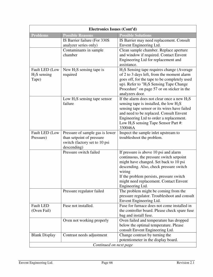
Envent Engineering Ltd. Page 66 Revision 2.1
Electronics Issues (Cont’d)
Problems Possible Reasons Possible Solutions
IS Barrier failure (For 330S
analyzer series only)
IS Barrier may need replacement. Consult
Envent Engineering Ltd.
Contaminants in sample
chamber
Clean sample chamber. Replace aperture
and window if required. Contact Envent
Engineering Ltd for replacement and
assistance.
Fault LED (Low
H2S sensing
Tape)
New H2S sensing tape is
required
H2S Sensing tape requires change (Average
of 2 to 3 days left, from the moment alarm
goes off, for the tape to be completely used
up). Refer to "H2S Sensing Tape Change
Procedure" on page 57 or on sticker in the
analyzers door.
Low H2S sensing tape sensor
failure
If the alarm does not clear once a new H2S
sensing tape is installed, the low H2S
sensing tape sensor or its wires have failed
and need to be replaced. Consult Envent
Engineering Ltd to order a replacement.
Low H2S sensing Tape Sensor Part #:
330046A
Fault LED (Low
Pressure)
Pressure of sample gas is lower
than setpoint of pressure
switch (factory set to 10 psi
descending)
Inspect the sample inlet upstream to
troubleshoot the problem.
Pressure switch failed If pressure is above 10 psi and alarm
continuous, the pressure switch setpoint
might have changed. Set back to 10 psi
descending. Also, check pressure switch
wiring
If the problem persists, pressure switch
might need replacement. Contact Envent
Engineering Ltd.
Pressure regulator failed The problem might be coming from the
pressure regulator. Troubleshoot and consult
Envent Engineering Ltd.
Fault LED
(Oven Fail)
Fuse not installed. Fuse for furnace does not come installed in
the controller board. Please check spare fuse
bag and install fuse.
Oven not working properly Oven failed and temperature has dropped
below the optimal temperature. Please
consult Envent Engineering Ltd.
Blank Display Contrast needs adjustment Change contrast by turning the
potentiometer in the display board.
Continued on next page

Envent Engineering Ltd. Page 67 Revision 2.1
Electronics Issues (Cont’d)
Problems Possible Reasons Possible Solutions
Analyzer not
communicating
with PC
Multiple reasons could be
causing the analyzer to not
communicate properly with the
PC.
Check that the analyzer is ON.
Check that the communication cable is
properly connected.
If the software application was open before
connecting the communication cable from
the analyzer to the computer, close the
software and re-open it. Try again and
enable communication.
Analyzer not
turning ON
Blown fuse Check fuse in the controller board. Replace
if required.
Controller board Malfunction Consult Envent Engineering Ltd for a
controller board replacement.
Not using the appropriate
voltage rating
Make sure to use the appropriate voltage to
power the analyzer. DC controller boards
can be powered with 12 - 24 VDC and AC
controller boards can be powered with 110
to 240 VAC. Keep in mind that if solenoids
are controlled by the controller board, the
voltage must match the solenoids voltage
rating.
Red LED on
Sensor Block
Sensor block fault Re-zero sensor block. Refer to "Re-zero
Sensor Procedure" on page 55.
Check for green status led on sensor block
once procedure is done. If sensor LED stays
red, consult Envent Engineering Ltd for a
replacement.
Wiring not done properly Make sure the wiring is done correctly.
Analog Outputs
(4-20 mA) not
working
Not using an external power
supply
The analog outputs in the controller board
are loop powered and not self-powered
unless AO boards were installed as per
customer request. If AO boards were not
requested, an external power supply must be
used. Refer to "Analog Outputs" on page 16
to see different wiring options.
Continued on next page

Envent Engineering Ltd. Page 68 Revision 2.1
Electronics Issues (Cont’d)
Problems Possible Reasons Possible Solutions
The system variable for output
has been modified.
By factory configuration, the analog outputs
(1 & 2) are configured to output based on
H2S Sample 1. Make sure that if they are
modified, that the right system variables are
selected.
Not coming out
of alarm
Alarms are latched If alarms are latched, they need to be
acknowledged. Go to the display> cycle
through until "ACK" is reached> press the
right button to acknowledge all latched
alarms.
To deactivate the latching on any alarm, use
the ICE software, and connect to the
analyzer and de-select latching on any alarm
that is latched.
The analyzer is actually in
alarm
Make sure the alarm setpoint values are as
desired and that the analyzer is below (or
above – like temperature setpoint) those
setpoint values.
Sample Conditioning System Issues
Problems Possible Reasons Possible Solutions
Liquid Carried
over in SCS
Sample too wet for current
conditioning sample system.
If a one-time occurrence: Cleaning required
for sample system, refer to "Sample
Conditioning System Cleaning Procedure"
on page 58.
If more than one time occurrence: Sample
conditioning system may need a system for
wet/dirty sample gas (extra filters set as
coalescing, add liquid float stops, etc.).
Consult Envent Engineering Ltd.
Regulator not
maintaining 15
psi (erratic H2S
readings)
Problems with the Regulator
(over pressured)
Replace Regulator, Consult Envent
Engineering Ltd.
Liquid carried over into
regulator
Consult Envent Engineering Ltd.
Problems with the (50 psi)
sample pre-regulator at the
sample point.
Heated regulator may be required if liquid
hydrocarbon carry over is present at the pre-
regulation sample.
Continued on next page

Envent Engineering Ltd. Page 69 Revision 2.1
Sample Conditioning System Issues (cont’d)
Problems Possible Reasons Possible Solutions
Pressure gauge
not working
Over pressured gauge Replacement is required. Consult Envent
Engineering Ltd for replacement.
Flowmeter not
working
Liquid carried over into
flowmeter
Consult Envent Engineering Ltd.
Frozen
humidifier
Analyzer is being exposed to
temperatures below 0 degress
°C (or - 2 degress °C if 5%
acetic acid is used)
Do not expose analyzer to temperatures
below 0 degress °C or - 2 degress °C
Humidifier
leaking liquid
The humidifier body cracked -
Could be due to extreme
temperature changes.
A replacement may be required. Consult
Envent Engineering Ltd for a replacement.
Calibration Issues
Problems Possible Reasons Possible Solutions
Change gain
more than +/-
25% from
original gain
after calibration
Not using the right calibration
bottle
Make sure the calibration bottle is within
analyzer range. It is recommended that
calibration gas used is close in value to
where the alarm setpoint values need to be
(for more accuracy).

Envent Engineering Ltd. Page 70 Revision 2.1
APPENDICES
Modbus Registry
Please note that due to differences in PLC's, these registries may be shifted by one
value. These can be modified if necessary using the H2S software.
Coils
MODICON 32-bit
Standard protocol
Enron Protocol
Discrete Output 1 Solenoid 1 0000 1001
Discrete Output 2 Solenoid 2 0001 1002
Discrete Output 3 Solenoid 3 0002 1003
Discrete Output 4 Solenoid 4 0003 1004
Discrete Output 5 Relay 1 0004 1005
Discrete Output 6 Relay 2 0005 1006
Discrete Output 7 Relay 3 0006 1007
Discrete Output 8 Relay 4 0007 1008
Discrete Output 9 Virtual Output 1 0008 1009
Discrete Output 10 Virtual Output 2 0009 1010
Discrete Output 11 Virtual Output 3 0010 1011
Discrete Output 12 Virtual Output 4 0011 1012
Discrete Output 13 Virtual Output 5 0012 1013
Discrete Output 14 Virtual Output 6 0013 1014
Discrete Output 15 Virtual Output 7 0014 1015
Discrete Output 16 Virtual Output 8 0015 1016
Floating Point
MODICON 32-bit
Standard protocol
Enron Protocol
Sample Current Value (H2S) 40001 7001
Sample RRA (H2S) 40003 7002
Analog Input Sensor 40004 7003
Board Temperature (°C) 40007 7004
Board Temperature (°F) 40009 7005

Envent Engineering Ltd. Page 71 Revision 2.1
Recommended Spare Parts List
Part Number Quantity Description
330053 1 Eductor Block
330063
(330063D for SDS)
1 Humidifier Rebuild kit c/w Elbows, Nafion
Tube, ftg
330079 2 Rear Window & Gasket
330100 - 330110 1 or (2
for SDS)
Aperture Strip (Associated to measurement
range)
330130 1 4 liter Containers of Acetic Acid
330133XS 12 300' Lead Acetate Tape (H2S Sensing Tape)
330406 1 Box of 10 Micro Filter Glass Fiber Element
12/19-57-50CSK
330423 2 13'' Chubby Quartz Tube (Total Sulfur
option only)
3300429 1 TS Ceramic Heater (Total Sulfur option
only)
330431 4 Kalrez O-rings (Total Sulfur option only)
330900 1 Tubing, Cleaner, Fittings Maintenance Kit
Chico A Sealing Compound: For sealing fittings in Hazardous Locations
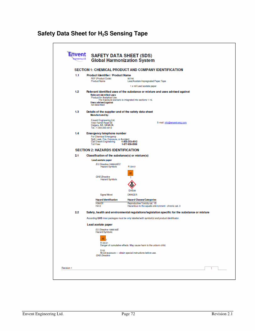
Envent Engineering Ltd. Page 72 Revision 2.1
Safety Data Sheet for H2S Sensing Tape
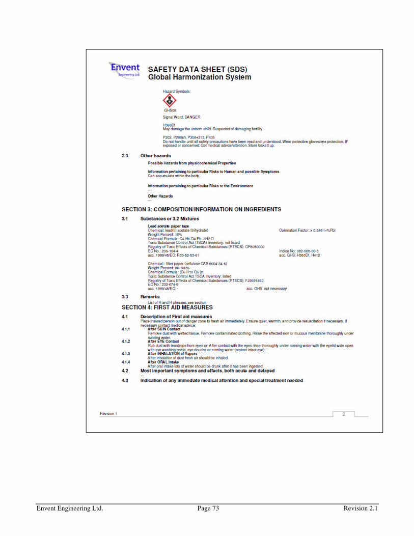
Envent Engineering Ltd. Page 73 Revision 2.1

Envent Engineering Ltd. Page 74 Revision 2.1

Envent Engineering Ltd. Page 75 Revision 2.1
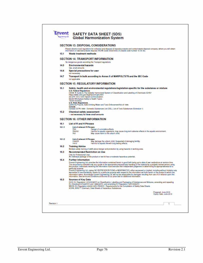
Envent Engineering Ltd. Page 76 Revision 2.1
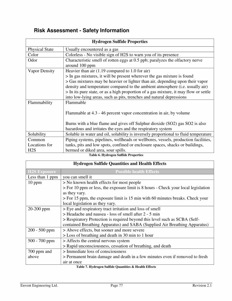
Envent Engineering Ltd. Page 77 Revision 2.1
Risk Assessment - Safety Information
Hydrogen Sulfide Properties
Physical State Usually encountered as a gas
Color Colorless - No visible sign of H2S to warn you of its presence
Odor Characteristic smell of rotten eggs at 0.5 ppb; paralyzes the olfactory nerve
around 100 ppm
Vapor Density Heavier than air (1.19 compared to 1.0 for air)
> In gas mixtures, it will be present wherever the gas mixture is found
> Gas mixtures may be heavier or lighter than air, depending upon their vapor
density and temperature compared to the ambient atmosphere (i.e. usually air)
> In its pure state, or as a high proportion of a gas mixture, it may flow or settle
into low-lying areas, such as pits, trenches and natural depressions
Flammability Flammable
Flammable at 4.3 - 46 percent vapor concentration in air, by volume
Burns with a blue flame and gives off Sulphur dioxide (SO2) gas SO2 is also
hazardous and irritates the eyes and the respiratory system
Solubility Soluble in water and oil, solubility is inversely proportional to fluid temperature
Common
Locations for
H2S
Piping systems, pipelines, wellheads or wellbores, vessels, production facilities,
tanks, pits and low spots, confined or enclosure spaces, shacks or buildings,
bermed or diked area, sour spills. Table 6. Hydrogen Sulfide Properties
Hydrogen Sulfide Quantities and Health Effects
H2S Exposure Possible health Effects
Less than 1 ppm you can smell it
10 ppm > No known health effects for most people
> For 10 ppm or less, the exposure limit is 8 hours - Check your local legislation
as they vary.
> For 15 ppm, the exposure limit is 15 min with 60 minutes breaks. Check your
local legislation as they vary.
20-200 ppm > Eye and respiratory tract irritation and loss of smell
> Headache and nausea - loss of smell after 2 - 5 min
> Respiratory Protection is required beyond this level such as SCBA (Self-
contained Breathing Apparatus) and SABA (Supplied Air Breathing Apparatus)
200 - 500 ppm > Above effects, but sooner and more severe
> Loss of breathing and death in 30 min to 1 hour
500 - 700 ppm > Affects the central nervous system
> Rapid unconsciousness, cessation of breathing, and death
700 ppm and
above
> Immediate loss of consciousness
> Permanent brain damage and death in a few minutes even if removed to fresh
air at once Table 7. Hydrogen Sulfide Quantities & Health Effects
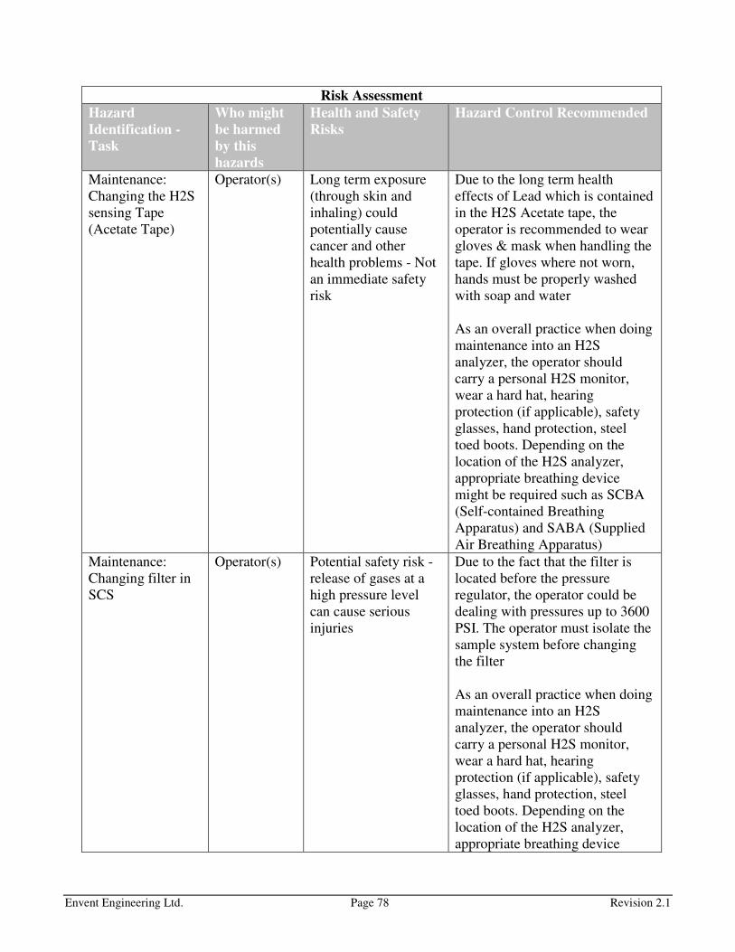
Envent Engineering Ltd. Page 78 Revision 2.1
Risk Assessment
Hazard
Identification -
Task
Who might
be harmed
by this
hazards
Health and Safety
Risks
Hazard Control Recommended
Maintenance:
Changing the H2S
sensing Tape
(Acetate Tape)
Operator(s) Long term exposure
(through skin and
inhaling) could
potentially cause
cancer and other
health problems - Not
an immediate safety
risk
Due to the long term health
effects of Lead which is contained
in the H2S Acetate tape, the
operator is recommended to wear
gloves & mask when handling the
tape. If gloves where not worn,
hands must be properly washed
with soap and water
As an overall practice when doing
maintenance into an H2S
analyzer, the operator should
carry a personal H2S monitor,
wear a hard hat, hearing
protection (if applicable), safety
glasses, hand protection, steel
toed boots. Depending on the
location of the H2S analyzer,
appropriate breathing device
might be required such as SCBA
(Self-contained Breathing
Apparatus) and SABA (Supplied
Air Breathing Apparatus)
Maintenance:
Changing filter in
SCS
Operator(s) Potential safety risk -
release of gases at a
high pressure level
can cause serious
injuries
Due to the fact that the filter is
located before the pressure
regulator, the operator could be
dealing with pressures up to 3600
PSI. The operator must isolate the
sample system before changing
the filter
As an overall practice when doing
maintenance into an H2S
analyzer, the operator should
carry a personal H2S monitor,
wear a hard hat, hearing
protection (if applicable), safety
glasses, hand protection, steel
toed boots. Depending on the
location of the H2S analyzer,
appropriate breathing device
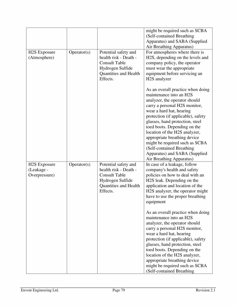
Envent Engineering Ltd. Page 79 Revision 2.1
might be required such as SCBA
(Self-contained Breathing
Apparatus) and SABA (Supplied
Air Breathing Apparatus)
H2S Exposure
(Atmosphere)
Operator(s) Potential safety and
health risk - Death -
Consult Table
Hydrogen Sulfide
Quantities and Health
Effects.
For atmospheres where there is
H2S, depending on the levels and
company policy, the operator
must wear the appropriate
equipment before servicing an
H2S analyzer
As an overall practice when doing
maintenance into an H2S
analyzer, the operator should
carry a personal H2S monitor,
wear a hard hat, hearing
protection (if applicable), safety
glasses, hand protection, steel
toed boots. Depending on the
location of the H2S analyzer,
appropriate breathing device
might be required such as SCBA
(Self-contained Breathing
Apparatus) and SABA (Supplied
Air Breathing Apparatus)
H2S Exposure
(Leakage -
Overpressure)
Operator(s) Potential safety and
health risk - Death -
Consult Table
Hydrogen Sulfide
Quantities and Health
Effects.
In case of a leakage, follow
company's health and safety
policies on how to deal with an
H2S leak. Depending on the
application and location of the
H2S analyzer, the operator might
have to use the proper breathing
equipment
As an overall practice when doing
maintenance into an H2S
analyzer, the operator should
carry a personal H2S monitor,
wear a hard hat, hearing
protection (if applicable), safety
glasses, hand protection, steel
toed boots. Depending on the
location of the H2S analyzer,
appropriate breathing device
might be required such as SCBA
(Self-contained Breathing

Envent Engineering Ltd. Page 80 Revision 2.1
Apparatus) and SABA (Supplied
Air Breathing Apparatus)
Floating the
Sample system &
analyzer
Operator(s) Not immediate safety
and health concern
If the analyzer is floated, the
analyzer needs to be immediately
isolated, turned off and cleaned.
Refer to "Sample Conditioning
System Cleaning Procedure" on
page 58
As an overall practice when doing
maintenance into an H2S
analyzer, the operator should
carry a personal H2S monitor,
wear a hard hat, hearing
protection (if applicable), safety
glasses, hand protection, steel
toed boots. Depending on the
location of the H2S analyzer,
appropriate breathing device
might be required such as SCBA
(Self-contained Breathing
Apparatus) and SABA (Supplied
Air Breathing Apparatus)
Voltage hazards Operator(s) Immediate safety and
health risk.
It is important that the operator is
trained on handling the analyzer
when it is on. The analyzer does
not need to be off when it goes
into maintenance. However, it is
very important that the operator is
aware of the danger of an electric
shock
TS Enclosure heat Operator(s) Medium safety risk The inside of the Total Sulfur
Enclosure can get up to 900 °C,
however, the outside walls will
only reach approximately 150 °C.
Do not touch surface of the TS
enclosure when operating. If the
TS enclosure needs to be serviced,
allow 1 hour after powering down
the analyzer to cool down
Electrostatic
hazard - Explosion
hazard
Operator(s) Immediate safety and
health risk.
Electrostatic Hazard – Backpan
and Certification nameplate must
be cleaned only with a damp cloth
to prevent static charging hazard
which could result in an explosion Table 8. Risk Assessment

Envent Engineering Ltd. Page 81 Revision 2.1
This document has been continuously improved and revised over time; see the table below for revision
(rev) information.
Revision No. Revision Date Revision Description
0 15 April 2016 New and Updated 330S-DS / 331S-DS Manual
1.0 12 Oct 2016 Updated information on analysis cycle + Fix minor mistakes
2.0 19 May 2017 Section updates on manual based on 61010 Standard updates
2.1 28 Dec 2017 Updated Standard section to 61010 Standards
Decimal increases on revision numbers (E.g. Rev 1.0 to Rev 1.1) on this user manual means that content
changes will not affect or contradict Intertek certification documentation, thus the notified body does not
need to be informed of the changes; for instance, improving writing or layout. A full unit change (E.g.
Rev 1.0 to Rev 2.0) will mean that the content changes must be communicated and updated to the
notified body.
For further information, or a copy of our most recent operating manual, please visit us at www.envent-
eng.com. Envent Engineering Ltd reserves the right to change product design and specifications at any
time without prior notice