[i .arv opv - nasa · [i .arv,opv,o *', l: langleyresearchcenter library,nasa hamrton,...
TRANSCRIPT
NASA-TM-84593 19840018997NASA Technical Memorandum 84593
ANALYSISOF LATERALAND TORSIONALVIBRATIONCHARACTERISTICSOF BEAMSAND SHAFTSWITHENDLOCATEDROTATIONALMASSES
DANIEL K, ROBERTSON
MAY 1984
[I .ARV,OPV,o *', L:
LANGLEYRESEARCHCENTERLIBRARY, NASA
HAMRTON, VIRGINIA
N/ ANationalAeronauticsandSpace Administration
Langley ResearchCenterHampton,Virginia23665
https://ntrs.nasa.gov/search.jsp?R=19840018997 2018-06-11T14:00:51+00:00Z

SUMMARY
Equations of motion are derived for free vibration of a uniform straight
free-free beam with a rotational mass attached at each end. The mode-shapes are
shown to be linear combinations of trigonometric and hyperbolic sine and cosine
functions. By using boundary conditions, nonlinear algebraic equations are derivedfor both lateral and torsional vibrations. These solutions can then be used to
compute natural frequencies and mode shapes.
A computer program was written to solve the nonlinear algebraic equations.
This program uses the Newton-Raphson method to compute natural frequencies, modeshapes and node points for any number of modes, for any given parameters.
INTRODUCTION
The lateral and torsional vibration characteristics in the design of certainsystems subject to external interference are not fully understood. Some common
examples of such systems are the wing of an aircraft, the base of reciprocating
engine, and the hull of a ship. Some of these systems can be effectively
approximated by a single beam with varying end conditions. This paper will dealwith the characteristics of free vibration of such beams.
Both the properties of natural frequency and location of node pointsprovide the designer with those tools needed to either minimize or maximize the
vibration of a system• Knowledge of the natural frequency of a system allows a
designer to avoid resonance. If a concentrated force is located at a node point,
then the induced vibration will be minimized. These characteristics are easilyobtainable from tables of predetermined eigenvalues for simple beams such as
cantilever, hlnged-hinged, and a few others (refs. I, 2, 3). However, the problem
is more complicated for those configurations having something other than a hinged,clamped, or free end mass.
This paper describes the derivation of the differential equations for free
vibration. The linearized equations satisfying the various boundary conditions,will then be obtained using the methods discussed in reference I. The
configuration to be considered is a free-free beam with rotating masses at both
extremities. This configuration is considered to be the most general case, with
all the classic cases able to be represented by the lower and upper limitingcases. The computer program FFBEAM which computes mode shapes, nodal points and
natural frequencies of free vibration is discussed in the text of this paper. A
listing of FFBEAM and sample input and output are also included in the appendices.

SYMBOLS
A cross sectional area of beam or shaft
AI,BI,CI,D 1 coefficients of mode shape equation
E dimensionless position variableE1 stiffness of beam
G modulus of rigidity
I polar moment of inertiaP
11 inertia of mass at x = 0
12 inertia of mass at x = L
L length of beam or shaft
mI mass at x = 0 on beam
m2 mass at x = L on beam
M moment
M1 moment of x = 0 on beam
M2 moment of x = L on beam
P(t) time solution of partial D.E.
r(x),r(_) lateral mode shapet time
T torque
TI torque at x = 0 on beam
T2 torque at x = L on beam
v(x,t) lateral displacement of beamV shear force
VI shear at x = 0 on beam
V2 shear at x = L on beam
X location on axis of beam or shaft
Z(6) eigenvalue matrix
phase angle (rad)
B eigenvalue variable
g dimensionless position variable
B(x) torsional mode shape
P density of beam or shaft
i(x,t) angular displacement of shaft
rotational velocity (rad/sec)
2
DIFFERENTIAL EQUATION OF LATERAL FREE VIBRATION
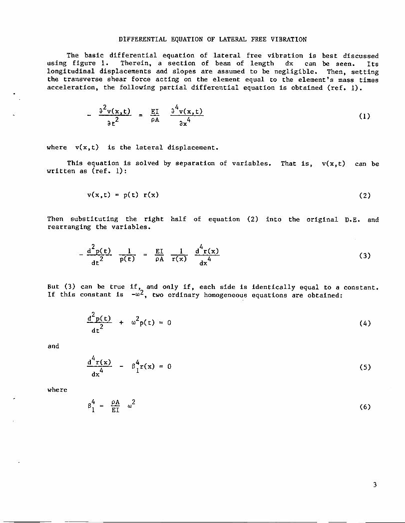
The basic differential equation of lateral free vibration is best discussed
using figure I. Therein, a section of beam of length dx can be seen. Its
longitudinal displacements and slopes are assumed to be negligible. Then, setting
the transverse shear force acting on the element equal to the element's mass times
acceleration, the following partial differential equation is obtained (ref. I).
_2v(x,t) E1 D4v(x_t)= -- (1)3t 2 pA 3x 4
where v(x,t) is the lateral displacement.
This equation is solved by separation of variables. That is, v(x,t) can bewritten as (ref. I):
v(x,t) = p(t) r(x) (2)
Then substituting the right half of equation (2) into the original D.E. andrearranging the variables.
d2y(t) I E1 1 d4r(x)= (3)dt2 p(t) OA r(x) dx4
But (3) can be true if, and only if, each side is identically equal to a constant.
If this constant is _m2, two ordinary homogeneous equations are obtained:
d2p(t) + _2p(t) = 0 (4)dt2
and
d4r(x) B_r(x)= 0 (5)dx4
where
4 pA 2
Bl = E-Y _ (6)
The solutions for (4) and (5) are (ref. I):
r(x) = AlSln 8x + BlCOS 8x + ClSlnh Bx + DlCOSh Bx
and
p(t) = cos(_t - _) (7)
where e represents the phase angle. But this solution is more convenient to use
in its nondimenslonallzed form. Therefore, the new variable € = x/L, where L is
the length of the beam, is introduced. The solution of displacement after thesubstitution is found to be
r(_) = Alsin 82€ + B1 cos 82_ + Clsinh 82E + DlCOSh 82€ (8)
where
4 pA 2 L482 = _ (9)
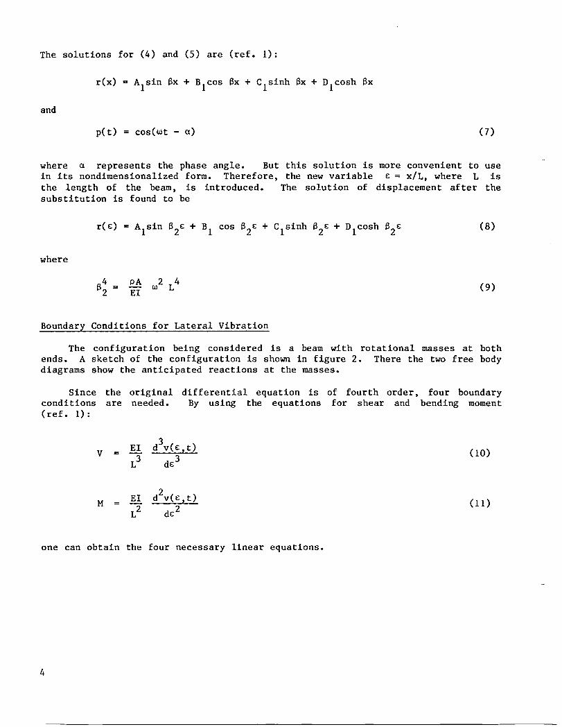
Boundary Conditions for Lateral Vibration
The configuration being considered is a beam with rotational masses at both
ends. A sketch of the configuration is shown in figure 2. There the two free body
diagrams show the anticipated reactions at the masses.
Since the original differential equation is of fourth order, four boundaryconditions are needed. By using the equations for shear and bending moment(ref. i):
V = E__[Id3v(€,t) (I0)L3 d_3
M = E1 d2v(€,t) (If)L2 dc2
one can obtain the four necessary linear equations.
4
I. Following reference ! and referring to figure 2, the first boundary condition
involves the shear V1:
E1 d3v(E,t) d2v(€,t)= = mI at _ = 0 (12)
- V1 L3 dc3 dt2
By substituting the rlght-hand side of equation (2) into equation (12), the
following is obtained:
E1 d3r(E) p(t) = mlr(€) d2p(t) (13)L3 d£3 dt2
Equation (4) can be rewritten as:
d2p(t)
dt2 _ _2 (14)p(t)
Using equation (14) in equation (13), we have:
_2 mlr(€) E1 d3r(€) = 0 (15)L3 d£3
or
d3r(£) m 1
= 6_r(g) at € = 0 (16)d3 pAL
where 62 is given by equation (9).
II. The derivation of the second boundary conditions employs the same procedure as
that of the first boundary condition. The only difference is that they are
applied to the mass m2 and shear V2. The resulting equation is:
d3r(€) -m 2= B_r(_) at € = I. (17)
dc3 PAL
5
III. Following reference I, the third boundary condition involves the moment M1
(see figure 2):
M1 = ll_(g,t ) = E1 d2r(g)L2 dg2 p(t) at g = 0 (18)
By assuming small angular displacements, one may represent O(g,t) by the slopewl
_v(x,t)/_x. Therefore, using equation (2), for small displacements, 0 can
be approximated by:
dr(x) "• p(t)dx
thereby obtaining:
M 1 = 11 dr(g) d2p(t) = E1 d2r(g) • p(t) (19)L dg dt2 L2 dg2
By using equation (14), equation (19) can be reduced:
2
d2r(g) I1 L m dr(g)= (20)
dg2 E1 dg
or
d2r(g) -II 4 dr(g)
dg2 = pAL 3 62 dE at g = 0 (21)
IV. The fourth boundary condition uses the same method as the third. After
employing the same steps as outlined above, the following is obtained:
d2r(g) 12 4 dr(g)
dg2 pAL3 62 dg at g 1. (22)
By substituting equation (8) and appropriate values of g (i.e., g = 0 at oneboundary and g = I at the other boundary) into equations (16), (17), (21)
and (22), the following four linear equations are obtained:
6

mlB2 mlB2- A1 pAL B1 + C1 pAL D1 = 0 (23)
• ) )\_-_-- sin 62- cos B2 A1 + \p-AL--cos 62+ sin B2 B1
+ \_-- sinh 62+ cosh B C 1 + \_-_-- cosh 62+ sinh 62 D1 = 0 (24)
3116_ I162
A I - B1 + CI + D! = 0 (25)pAL3 pAL3
' PAL3 cos 62- sin 6 A1 +\p--_L3 sin 62- cos 6 B1
+ - 1262 cosh 62+ sinh 6 CI + 1262 sinh 62+ cosh 6 D1 = 0 (26)pAL3 pAL3
Obtaining Nontrivial Solutions
Equations (23)-(26) can be compactly written in the vector-matrix fo_ as
follows:
Z(62 C1 = 0 (27)
D1
where Z(B) is the 4 x 4 coefficient _trix whose entries are functions of 6.
Non-zero solutions (AI, BI, CI, DI, ) exist only when the determinant of• Z(6) is zero. Therefore, the first step in obtaining non-trivial solutions is to
obtain t_ real solutions of the nonlinear equation:
det _(62)] = 0 (28)
where det [ ] denotes the determinant.
A solution B* is substituted back in equation (27), and a degenerate system
(usually of rank 3) of algebraic equations is obtained. Making A1 = I, the
remaining three coefficients BI, C1 and D1 can be uniquely determinedfor each 6*. The computer program MACSYMA was used to carry out these proce-
dures. A listing and description of the steps can be found in Appendix C. The
resulting determinant of Z(B) obtained in MACSYMA is used in the program FFBEAMwhich is discussed below.
PROGRAM DISCUSSION
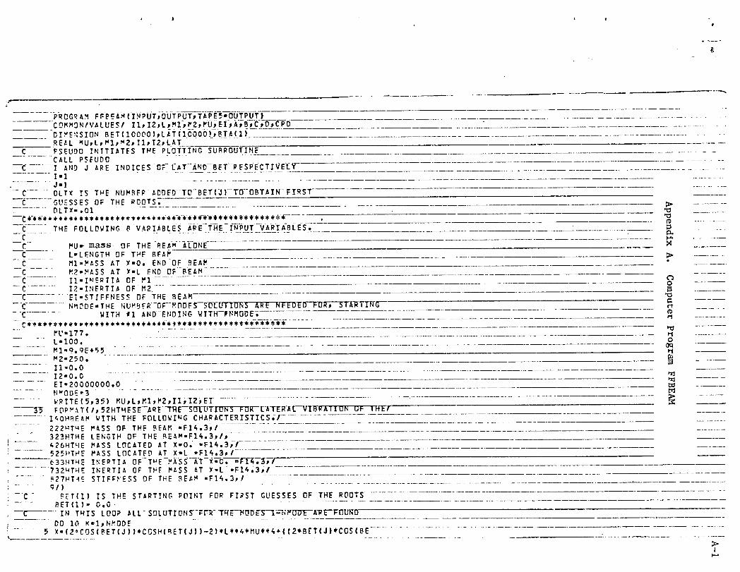
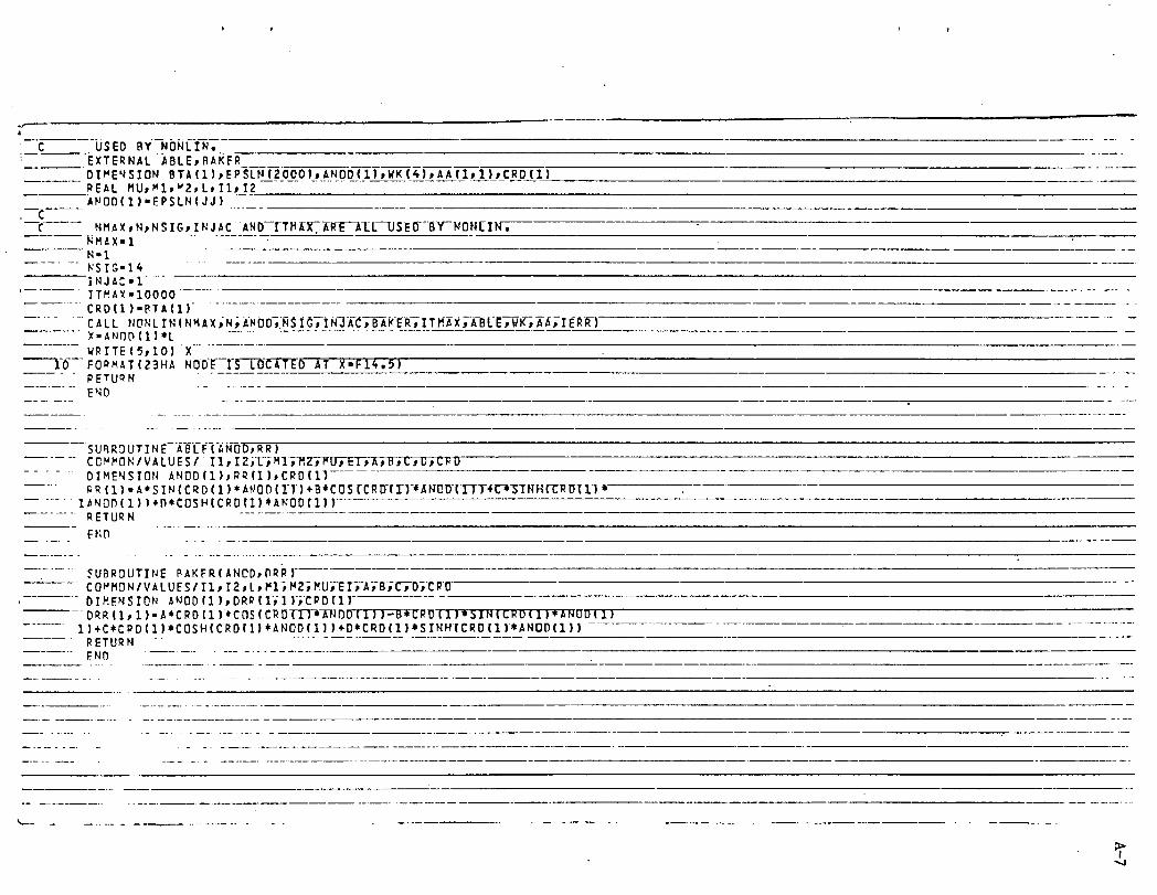
The computer program FFBEAM (see Appendix A for a listing) was written for the
purpose of calculating non-trivlal solutions using the method described in the
preceding section. FFBEAM calculates the frequencies of vibration, mode shapes and
the locations of nodes for any number of modes.
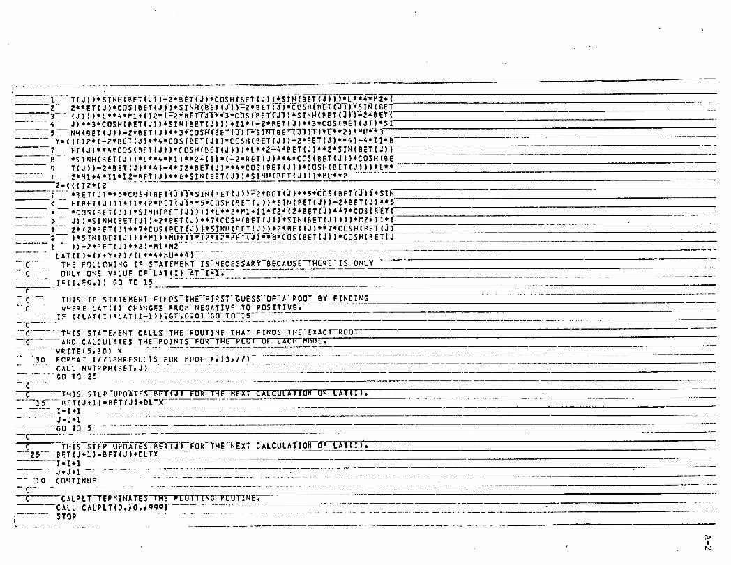
The program uses a simple root-finding subprogram (NONLIN) that employs theNewton-Raphson method to find the eigenvalues of the determinant. The size of the
equation representing the determinant necessitated the separation of the equation
into three separate quantities that are subsequently added together. FFBEAM uses
the subprogram GELIM (for Gauss (-Seidel) elimination) to solve the degenerate
system of equations (eq. 28) discussed in the previous section.
After computing the values of 6, AI, BI, C1 and D1 fromequations (27) and (28), the program uses simple substitution to find the
frequencies. The subprogram NONLIN is again used to find the node points of the
mode shape equation. A further explanation of the input as well as output is givenbelow.
PROGRAM OPERATION
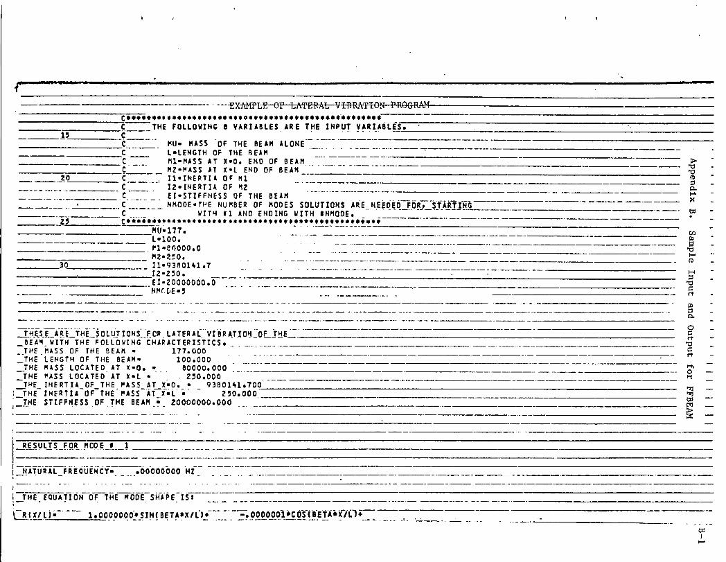
Input.- A total of eight input variables is needed to run FFBEAM. Aconsistent set of units is needed for the input (meters-kilograms-seconds or
feet-pounds-seconds is recommended). The necessary input information includes two
concentrated endpoint masses (M! and M2), two endpoint inertias (11 and 12),
beam mass and length (MU and L, respectively), beam stiffness (El), and thenumber of modes solutions are needed for (NMODE). Because of the small number of
input variables the input can simply be written in the text of the program. A
listing of sample input is given in Appendix B.
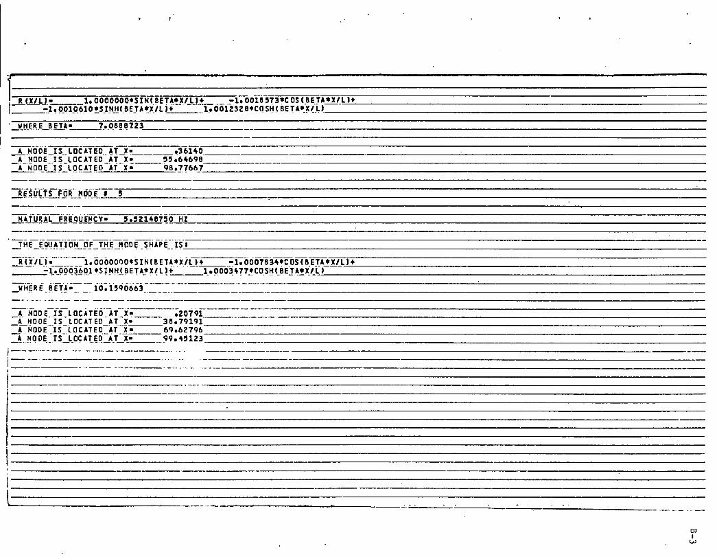
Output.- The output computed by FFBEAM includes the natural frequency ofvibration, elgenvalue, mode shape equation and the location of node points for each
mode. A listing of sample output is given in Appendix B. The first three pages of
Appendix B include the frequencies, node positions, elgenvalues and mode shapeequations. The final pages of Appendix B are the plots corresponding to each of
the modes. These plots were found useful in identifying the relative motion of
points of interest on the beam.
THE DIFFERENTIAL EQUATION OF TORSIONAL VIBRATION
The differential equation of torsional vibration will be derived next, usingthe method described in reference I. This method utilizes a differential element
of a shaft of length dx (as seen in fig. 4) and the dynamic equilibrium of thiselement.
It is known that the torque at any position of a circular shaft may be writtenas (ref. I):
T = GI _(x,t)p _x (29)
Utilizing equation (29) and the differential element shown in figure 3, it followsthat the net torque acting on the element at any time is (ref. I):
___T dx = GI 32#(x_t) dx (30)_x p 8x2
This torque is opposed by an inertial torque:
_2_(x_t) dx (31)- Ipp _t2
Hence, sum of these torques must be zero, and the differential equation governingtorsional vibration of circular shafts is:
_2#(x,t) = G _2_(x,t)
_t2 p _x2 (32)
This equation can also be solved by separation of variables. The angulardisplacement of the shaft is written as:
_(x,t) = p(t) 8(x) (33)
Then, after substituting into equation (32) and rearranging, gives:
1 d2p(t) G 1 d28(x)(34)
p(t) dt 2 p O(x) dx2
The solutions for both 8(x) and p(t) are obtained by setting both sidesequal to -m2:
p(t) = cos(mr - a) (35)
8(x) = A1 sin m _ x + B1 cos _ x (36)
9
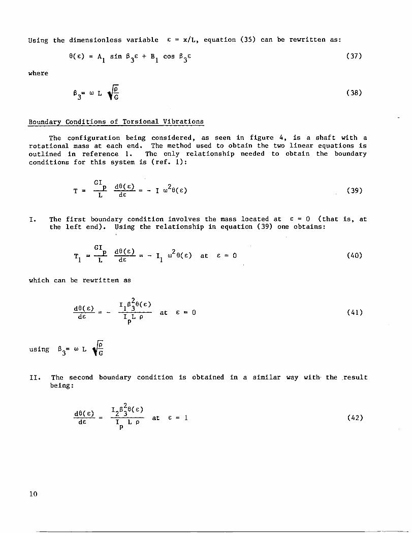
Using the dimensionless variable e = x/L, equation (35) can be rewrittenas:
8(e) = AI sin B3e + BI cos 83e (37)
where
83= _ L _ (38)
Boundary Conditionsof TorsionalVibrations
The configurationbeing considered, as seen in figure 4, is a shaft with arotationalmass at each end. The method used to obtain the two linear equationsisoutlined in reference I. The only relationshipneeded to obtain the boundaryconditionsfor this system is (ref. I):
GIT = _ d0(e) = _ I _20(e) (39)L de
I. The first boundary conditioninvolves the mass located at e = 0 (that is, atthe left end). Using the relationshipin equation(39) one obtains:
GI
T1 =-_L d0Ce) =_-_ - Ii m28(e) at e = 0 (40)
which can be rewrittenas
dO(e) I18_8(e)--= at e = 0 (41)de I LP
P
using 83= m L
II. The second boundary condition is obtained in a similar way with the resultbeing:
dO(e) 128_0(e)--= at e = I (42)de I L P
P
i0
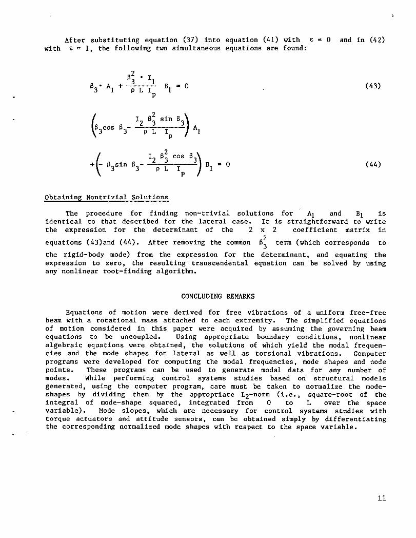
After substituting equation (37) into equation (41) with € = 0 and in (42)
with E = I, the following two simultaneous equations are found:
2 • iiB3
83" A1 + P L I B1 = 0 (43)P
12 83 sin 83 A13c°s 83- p L IP
2
(- 12 83 c°s 8_)B1 = 0 (44)
+ 83sin 83- P L Ip
Obtaining Nontrivial Solutions
i
The procedure for finding non-trivial solutions for AI and B1 isidentical to that described for the lateral case. It is straightforward to write
the expression for the determinant of the 2 x 2 coefficient matrix in2
equations (43)and (44). After removing the common 63 term (which corresponds to
the rigid-body mode) from the expression for the determinant, and equating the
expression to zero, the resulting transcendental equation can be solved by usingany nonlinear root-finding algorithm.
CONCLUDING REMARKS
Equations of motion were derived for free vibrations of a uniform free-free
beam with a rotational mass attached to each extremity. The simplified equationsof motion considered in this paper were acquired by assuming the governing beam
equations to be uncoupled. Using appropriate boundary conditions, nonlinear
algebraic equations were obtained, the solutions of which yield the modal frequen-
cies and the mode shapes for lateral as well as torsional vibrations. Computer
programs were developed for computing the modal frequencies, mode shapes and node
points. These programs can be used to generate modal data for any number of
modes. While performing control systems studies based on structural models
generated, using the computer program, care must be taken to normalize the mode-
shapes by dividing them by the appropriate L2-norm (i.e., square-root of theintegral of mode-shape squared, integrated from 0 to L over the space
variable). Mode slopes, which are necessary for control systems studies with
torque actuators and attitude sensors, can be obtained simply by differentiatingthe corresponding normalized mode shapes with respect to the space variable.
ii

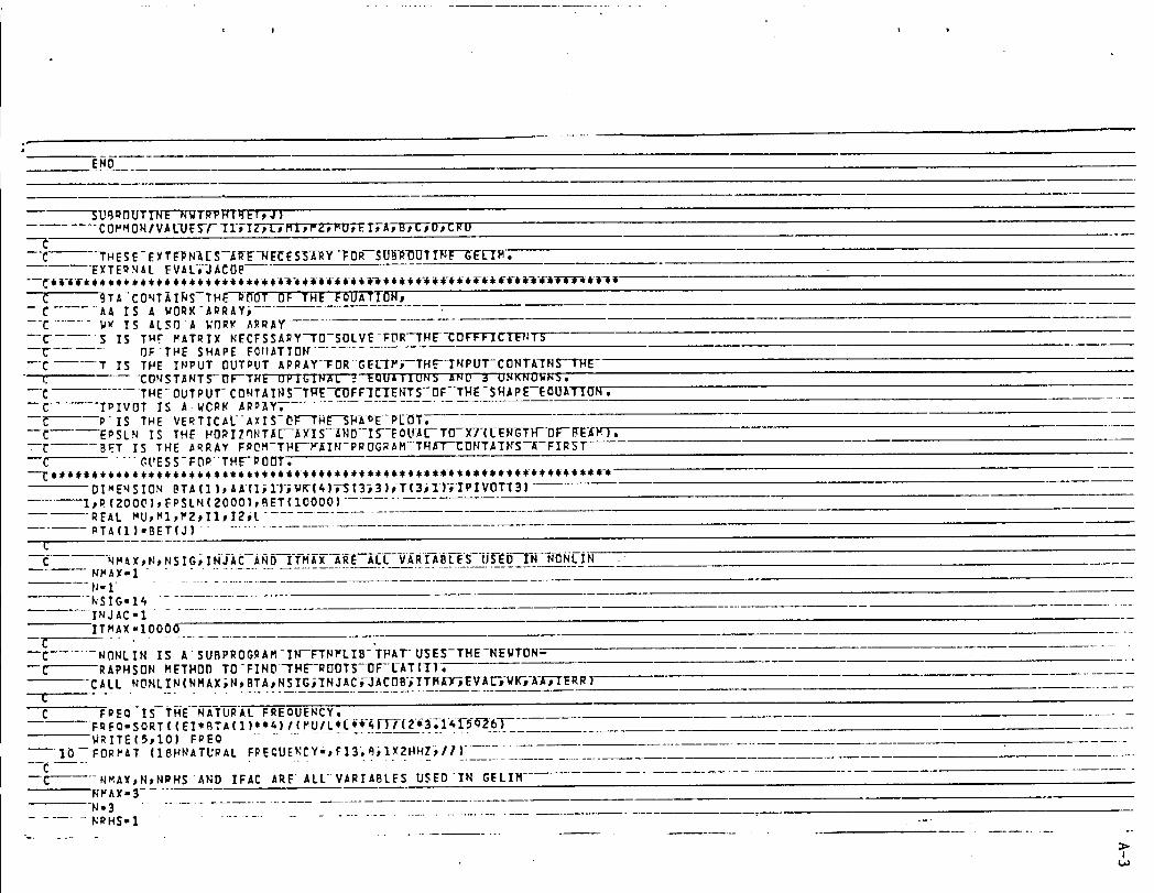
......... PROG_,A_ FFPE_,M(-I_-pUT_bUY PUT, TAP E_" OUTPUT) ................................................COMM3NfVALUES/ I1, IZ,L _MI_ _2j,PUJ,ElpAjB2C tD_,CPO ............
.... D !.'E_SION BET( 10000 }pL_T (lOO00t_BTA(I) .................................RE_L XUp LsMle M2p IlJ,12pLAT
C PSEUDO INITIATES THE PL-OTTING SUBROUTINE ...........CALL PSEUDO ...........
"---C...... I AND J ARE INDICES OF- _AT--_ND--BET--RESPECTIVEI_Y- _ ............... I'l............j.) ..........--C--- " DLTX !S T_E NUMBFR-ADDFO--TO-BET(_)-TO--OBT_IN-FIRST
C GUESSES OF THE RqO_T_S_t..................................... > .................DLTX- .01 '_
• (1)
-"-C.................... THE FOLLOWING B VARIABLES._E;-T_E-fN_U_T_V_A_R_-I_-_BLE-S. _ --.C _ ......
--f.- PU- mass. OF THE-BE_M-AL-ONE---.............C L,,,LENGTH OF T}_F BFAP > ........
-C ........ MI-P_SS AT X-O, END-OF-.9-EAM--C ...... MZ-MASS AT X,,'LEND OF BEAM .........--C ......... II-INERTIA OF P1 .......... o--C ...... 12-INERTI_ OF M2............... El
--C .......... El-STIFFNESS OF-THE-BEAM---C NM2DE-THE NUM_FR-OF--ROOFS--ST_FL-{._S--A'R7_'--NF-EO-EDFDR_ STARTING- m .......--C........ WITH _1 AND-ENDING WITH--#NMDDE. _.............. _ ..........
*****-***************************************************.... ,_PL"177, ....................................................... _t
..... L=IO0. ............................. 0Ml"9, qE+5_ rl
....... M2=250" . ..........Ii'O.O
............. 12-0.0 .......................
........... EI,,20000000.O .........................
....... N_ODE.3 .................. _
....... WRITE(5_35) MU_,L_HI _M2_I 1P 12], E7................................... _ ........--_B FOP,"AT(I_ 52HTHESE'--ARE-TRFSI3[I.IT_R--[K_[--V_BRAIIUN OF IHEI ............. I_OHBEhH UITH THE FOLLOWING CHhRACTERISTICS;I .......................................... _ ....................................
221_T4E M_SS OF THF BEA_ ,.F14,3_! .......................... 323HTHE LENGTH OF THE _EAM-FI_.o3_I_- ..................
:26HTHE M_.SS LOCATED AT ×-Oo -Ft_,3;f .................. __ ..............525HT_E PASS LOCATED hT X-t -FI_,3_/ ....
533.qTHE IKEPTIA OF-TUE PASS AT _(,,O.,,F_-'4_!......... ?32_THE INERTIA OF THE P_SS _T X-L--FI4;3_/....... F27HT_E STIFF._ESS OF THE BEAM -F14.3_,I
gl}-C - .eET{1) IS THE STARTING POINT FOR FIR._T GUESSES OF THE ROOTS ............. BET(I)- 0,0- " .....................--C ....... IN THIS LOOP _LL-SOLUTII]NS--FFR-TqE-MUDE'S-I--NFIZIffE_z_q_-I:[TUND
00 i0 K-I,N_ODE-- 5 X- (2_'COS(BET(J ))*CGSH(BET (J) )-2)*L**4*HU$*_'_' ((2*B{T (J)*CGS (BE ........................................
>!I,-,-,
--1 T(J))_ INH(FET(J) )-Z,BET (J)*COSH( BET (J) )eSIN (SET (J) ) |*Le*4*M 2+ (-----Z Ze_ET(J)*COS(BET(J))*SINH(BET(J-J}_Z*BET(J|eCOSH(BET(J));SIN(BET
.... 4- J)ee3eCOSH(BET(J))eSIN(BET(J)))+IZ*-(-2e_ET(_)e*3eCOS(_ET(J))*SI5--NH(_ET(J))-Z*BET(J)+I3+COS_{B_T(J)|_'$t_(B_T_]ll)}L-_2)_MU _
y.(((IZ*(-2eBET(JIteA*COS(BET(J))*COSH(BET(J))-Zi_ET(J)e+4)-_*TI_B7 ETfJ)ee_eCDS(_ET(J))*COSH(B_T(J)))eL*e2_4*FET(J)_2*SIN(BET(J) °)
..... e- $SINH(BET(J))$L$*4*M1)eMZA(II*('ZeBET[J)*e6*CD$(BET(J))eCOSH(BE------ q T(J))-ZeBET(J)**4)-4*IZ*BET(J)*eAeCO$(BET(J))*COSH(BET(J})IeLe*
t " Z¢MZ+4*IIeIZ*_FT(J)ee6*SINfBET(J))*SINH(BFT(J)))*MU*e2Z=(((I2*(Z
----_ .... ,n_T(j)**SeCO_H(BET(_)T, SIN(BET(J));Z,BET°(j)e,5_COS(BET(_)),SI_
H(_ET(J))I+II_(Z*PETiJj**5*COSH(_ET(J))*SIh(PET()))-Z_BET(J)**5• *COS(BET(J))* INHiBFT(J)')t)*L_*2*M1;II*I2*(2*BET(-J)e*?*COS(BET(> J))eSINH(_T(J))._*B_T(J)e*?*CDSH(BETfJ))*SIN(FET(J})|)eH2;II*I? Z*(ZeRETfJ)*e?ecos(BET{J))*_tNH(qFT(J)).ZeBET(J)eeTeCOSH(BET(J)
I ))-ZeBET(J)ee_I+MI*MZ.... LAT(1).{X.y+z)/(Le_,HU**&) ...................................--_........THE FqLL_WING IF STATEMENT-IS-NECES_ARY-B_CAUSE-_IHERE -Is- ONLY----
C OHLY O_E V_LUF DF-L_Tfl)-AT-I;I;-- "I_(I.EG.I} GO TO 15
- _ - THIS IF STATEMENT _IHPS-THE--FIRST_UESS-D_-_-ROOT-BY-_INDI_G-C ...... WUEQE tAT(E) CHaNGESFRDM-NEG_TIV_-TDPOSITIVE;
-- C---"
"--C...... THIS STATEMENT CALLS-THE-ROUTINE-THATFINDSTHE-EXACT-RDOT--_--_ND CALCUUATES TH_-FOI_T_"--I:I_R"-'F_--PLDTOF E_CH'IW_UE';-........ wRITf(5_O) K ..............................." 30 rqoMAT (II18HRFSULTSFDR MODE !;13tll) ......................
CALL NWTQPH(BET_J)...... GO TO 2_ .........................
C --THIS STEP-UPD_TE_T_E NEXT CALCULATIUN UF LAT(I),------]5--.....BET(J+I)-BET(J)+DLTX
I-I.I ............J=J+l ..........GO TO 5 ...................
--C-
C THIS STEP UPDATES BET(J) FOR THE NEXT CALCULATION DF LAT(1)'.---25 ....._ET(J+I)=BFT(J)+DLTX
I'I+I ................. J'J+l .........--- 10 CDNTINUF .....................................................-* _ .............................................
c C_LP_T-"rE_MIN_TI_"tHE PLUIIING POUIINE.C_tt C_LPLTfO._O.,qq¢I
'--.........STOP ......................................................................
>I
,
°_d"
END
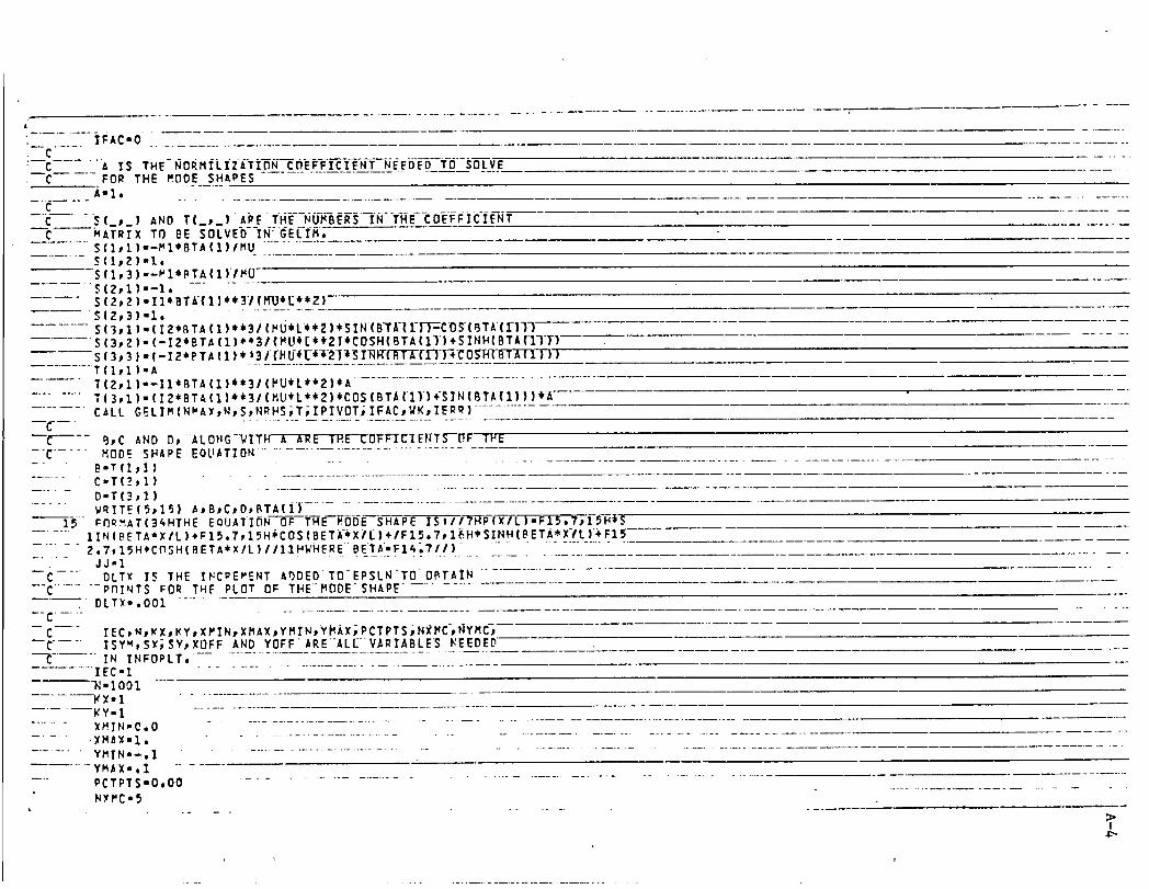
_U_DnUTT_TRPHf_ETp J )COf'H ONI VALIJES-F ]1/-I_ J,Lp'M1e r'2p cut Ei9 At Bt CpO_ CRU
--t--'C I HESE- EYTEP N-_[ S-J{KF_"-NE_ES_-A-i_ -i_ R--_O_-l_OUT rN_---GELIM,
E_tTER.qAL- EVAL;-_JACOB
C 9TA"CONTAINS--TH_.--_[TOT OF'THE EOUATIONpC 'AA IS A WORK-AgRAY_
---C ........ gk' IS ALsr'J A I_'flRK ARRAY'S IS T_._ MATRIX NECFSSARY-TD--SOLVE-FDR-'-THE--COFFVIClrt:'T'ITS
C" r3FTHE SHAPE FOIIATIDN ........C 1 IS THE INPUT OUTPUT ARRAY-_FDRGEL-I/"_--TH_-I_IPUT-CONTA-INS--T14E
.... F. 'C{]NST_NTS--I_F-TFfE_3I_-IIw"A'_'_.--EQUAIIUN3 _NU 3 uI4KNOWN_,,C THE- OUTPUT-'CONTAIF_'S-TI:fE--LrOFF'IC-_EFTTS--OF--T14E-SHAPE--EOUAT_ON. ....
--_-------'TPIVOT IS A.WCRK AR_Y, ..........._- P-IS THE VERTICALAXIS-O]_TNE--S_A_E-P[_OT;C E¢SLN IS THE HOPIZ_NT_L---AX-IS-_ND-IS--EOUA[--T_--X7-{L-EI_TH-OF-BE-_E),
-_-_ BF.T IS THE ARRAY FROH-THE---K_IFI-PRDGRAM-TF4FT--CDNTAIRS--_-FIRST--C ....GUE SS-FDRTHE-I_{]DT,
lpP (20001 _,FPSLN (ZOOO]_,BET( 100001 .........REAL MU_MI_MZtII_,I2PL "_TA(1)-BET(J| .................
C NM_X_,N_NSIG;IN-J-AC--At_{)---I-T-HAX ARE ALL VARIABLES USED IN NONLIN .NMAX" 1 ..........................N" 1...........kSIG'I_ ............ .--INJAC'IITMAX "10000
C .-
C NONLIN IS ASUBPROGRAM-IN--FTNMLIB-'THATUSES-THE-NEWTON-C RAPHSON METHOD TD-FIND-THE-RDOTS-DF-L-AT{I},
CALL NONL IN {NM AX_N_BTA _NSIG_'INJAC F3ACDB; ITM_(-iEVXL-_-WK_-A'ETIERR)
C F_'EQ-is-TH-E NATURAL FREOUENCY,FRFO-SORT { ( EI*BTA ( 1 )*'4) l {/'U I L'{'l ,i,,i,-i_FI-T(-2,_ 3:;-1_1-5-_3_6)$aRITE (5_,I0) FPEO
---'[O---FOR/_AT (18HNATIJRAL FRECUERCY'_,F13;_|;1),'2HNEj, I1) .....................................
--C---NMAY_,NtNPHS AND IFAC ARE ALL VARIABLES USEDIN GELIMNVAX=3--
-- N-3 "...... NRHS-I ........................................ ---
b>I
.... .......C .....
i--C........A IS THE-NORMILIZATION COEFFICIENT NEEDED TO SOLVE,mC FOR THE MODE SHAPES
A'l, .........C
-C .... $ (_,_) AND T(_p.| "APE TH_-NOM_-INT_CD_fFiCIENTC MATRIX TO BE SOLVED IN" GELIM,
............ S(]pl)._MI_BTA(I]/MU
.........S(I_Z)-I,S(IP3)--MIeFTA(E)/M0
....... S(2pi)--1,S(2_2)-II*BTA(1)*#31(MIJe[e#2|
---- S{213)'1, " ..........S(lpl).(IZ*BTA(1)*e31(MU_L*_)eSIN(BTK(_)-_COS-(_TA(_)-n _......S{3p2).(-12*BTA(1)**31(MUI[e_21_COSH(BTA(II)*SINH{BTA(II-T)S(3,3).{-12*PTA(1)*I3I{MUI_*I2|_SI_(-_[I-_0SI_(BTA{1 i))
.........T(Itl)-AT(2pl)._IIeBTA(1)ee31(MUeLe,2)_A ..................................T(3pZ).(12*BTA(1)_31(MUeL**2)eCDS(BT_(II)_SIN(fiT_(1)))_-K
....... C_LL G_LIM(NVAX_N_S_NRHS;T_IPIVOT;IFAC_WK_IE_)
-'C ..... MDD_ SHAPE EQUATION ..................................- " B-T(I_I) .........................................
....... C'T(_])D'T(3_I)
...... WRITE(St]5) _,B,CtD,BTA(I) ..........................15 _O_HAT(3_HTHE EOUATIDN OF THE MODE SHAPE IS:"11_HR(X/L)-Fl_.T_lS-H_S
...... IIN(B_TA*XIL]+FI_,7,1_H_COS(BETA*XiL)+IFIS;7_I_H*SINH(BETA_X-fL)_FI_
.........2,7,15H*C_SH(BETA*XIL)I/lIHWH_REBETA.FI_,?II) .................... __.JJ-1 _..
C DLTX IS THE I_C_EPENT A_DEDTO-EPSLN-TO-DBT_IN "--C ...... _nI_TS _OR THE PLOT OF THEMDDESHAPE .......... DLTX-,O01 ..... ......
C IECtNtKXtKYtXMINtXMAX_YMIN_YMbX_PCTPTS_NXMC_YMC_--C...... ISYW_SX;SY_XOFF AND YDFF-4RE-ALL-V_RI^BLES KEEDED-
_ IN INFOPLT, ..............................................IEC-I
_-1001_X-1 -KY-I ...............
....... XMIN-0,O .....................................................................
..... •XMa_-I, ..............................................................
.........YMIN--,I ...............................................................YMAX-,I "-
-- PCTPTS-O,OO ...............................................................
N_MC-5
>I
vI
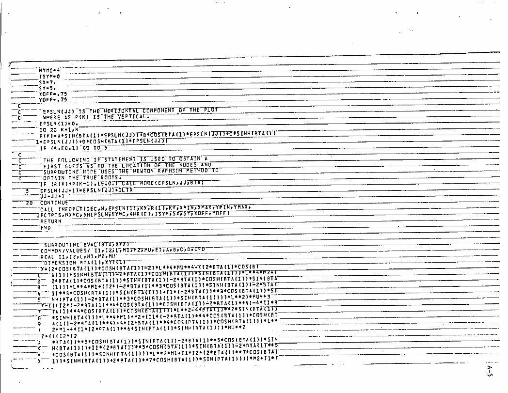
7NYHC=_ISYM-OSX=?.SY,,5.XOFF=,75YOFF-.75
C EPSL N [ J J ) -1 S--TH _--_-0R-I?O']_-_ AP-__L_IL--O T--_-- WHERE ,_$ _fK)IS-TH_VERTTC-J_-E-,.... EoSLN (1)=O;, ....
DO 20 K=I_NP ( v ) = A• SI N ( BTA( 1)$ EPSI.'14(;JJ) F_B 4_-L'_OS-(_-TE(-I.-)"F_p_;[_l ( jj ) )+C $SIt|_T'A-f"l..')
I*EPSLN(JJ ) ) +0$CO SH (BTA (1) ![_ PS[FF(J:J-||4
IF (K,EO,1)-GO TO 5C
--_---'- ....THE F_LLOWING IF--ST_TEME-N-T-_S'-I]-_O-TO--OB-T-E_NAC FIRST GUESS AS TO 'tHE LOCATION []F--'-THENOD'ES AND
--C--SUB_ OUT INF NqOE -USES--THE-NEWTOhrRF_[P-FIS{T_--METHDD-TO_ OBTAIN THE-TRUE- ROOTS,,
IF (_(K}$_ (K_I };, L-E;0;3-_I-EL---_DOE{E-FSL-N3-3_r_-BTA]5 EPSLN (JJ+1 )=EPSLN (-_-J1+_l)[-TX
jj=jj+] .........ZO CONTINUE
C._LL INFOP_T {IEC.. N:,,EP_[-N(I ) tKX,R-TI"T-;RV-;;X-M_-_P'_--_t YM_X,l PCTPTS_ NXMC:_5HE PS{ N-__Y_C_ 41_R{EI_I-SYM_S X-_SY-_XOFF_-YI']FF)RETURNFND
SUBQDUTIN_V_E(BT_)XY"!)
RFAL II,IZ_L_MI_MZ_MUDIMENSION_TA(1)_XYZ{I)
: I - A{I))_SINH[BT__ll_2_EI'-_"_D'S"FTFBI_II})*5/N{BTAII'}-_'MZ.{
Z-- Z_BTA(1)$COS(BT_(III$SI_{BT_(1));ZSBTK(II*COSH(BT_('I-)')$SINfBTA--3-- (1)))$L$$_$MI+(12$(-ZSBT_(T|_$3$COS(BT_(IT}_SINH{BT_(1]|=2*BTA(--4 I)$$3$COSH(BT_(1))$SIR(PT_(I))).II$(=2eBT_{I]$e3*CDS(BT_(1)]*SI--5 NH(PTA(1))-Z*BTA(I)$e3eC_SH(BT_(1))eSIN[BTA(I|)))eL*eZ)eMU$_3
_m(((IZ*(-Z$BT_(1)*$_*COS(BT_(11)$COSH(BT_(II)-ZeBTA(1)e_)-4*II*B
--_-- *SINH(BTA(II)*L**&$_I)*M_+(II$('Z*BTa(1)$$4_COS(BT_(1))$COSH(BTq-- A(1)I_2,_TA(1)e$4),&tIZSBTA(I|**4$COS(PTA[I))$COSH(BT_(]))),L,_
...... _ _*_I+_IIeIZe_TA(II*$6¢SIN(BT_(I|IeSINH(_T_(II||*MU**2 -"Z-(((IZ*(?
...... " *_Ta(1)**5*CDSH(BTA(1))*SIN(BTa(1))-?*PTa(1)**5*CDS(BTa(2))*SIN ........l( H(BTA(1)))+II$(2,BT_l{I-I'_5_COSFFIBTK(II)eSIN(BTK(I]I;ZiBT_(I}'_9..... . *COSIBTa(1))*SINHIBTAfl))))*L**2*M14IJ*I2*I2_BT_'tl)$*?_CDS(BT_
,- ...... )---- 1))_SINH(BTa(1)I+2$BT^[1)$,T,COSH(BTa(1)),SINIPTA(1))))$M2+II$ I
I
-1
, ? 2*(2*BTAf])**7*COS(BTA(1))*SINH(BTA(1))+Z*BTA(1)*e?*COSH(BTA(1))aSIN(BTA(I))IeM_I-*MU_n!I2*x_rIB_T_-I-I-I-_{BI_D_(fiTI-(T)I'I-CD'SRfB_XI
I---I----))-21_T_(1)*_)eMI*M 2YYZ(1)-(X*Y.?II([_{_MU__}RETU_fiEND-
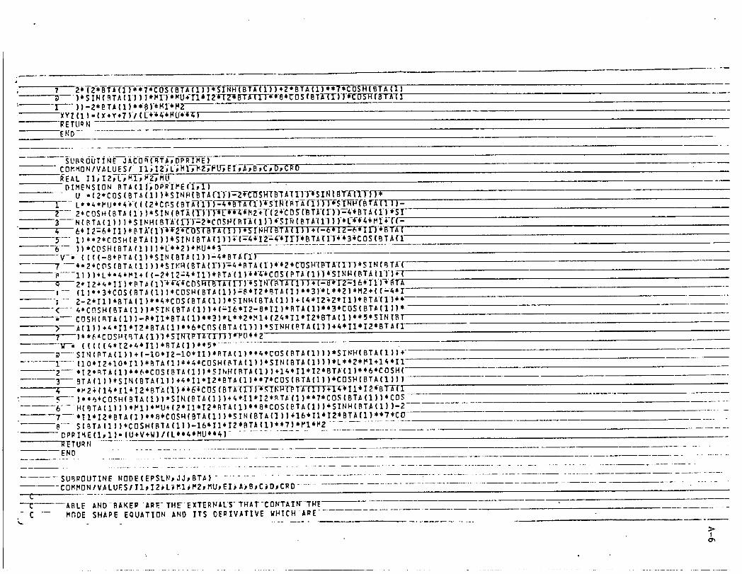
SUBROUTINE JACOB(BTApDPRIME)
REAL II_I2pLpMI_MZ_MUDIMENSION BTA(1)tDPR-IME(-ftl)
....... U •(2"COS (BTA(1)) iSINB(_TII-ITF_2TC-_SNIBT _l-1-l-F'rS-ll__I_TN*
--_-- 2*COSH (BTA (I} )*SIN (BTA (_)TF_-_MZ_T(21-C O_(B T_-(I_)T4€ BT_(£)-*-SI
6_ 12_6 iI])_BT[(IT_T2T_T-{-BT_-(_I-I-I-_-S-T_H(BTA (1))+ (-6' I2z6'TT1-1-*BTA (-_-- I)€.2,COSHI_TA{]))_SINfBT_III+-I:41II2_4-¢II-I_BTATIII*31COSIBTA{_
))*CDSH(BTA(1)))eL'¢I2)_MUe¢_V-.-{(({-BIBTA{1)_SIN(BT_(1))_4eBT_TI}
? --e*2*CDS{BTA(1)))_SIHB(BT_(_)]_4_BTA-(1)__2*COS_-(BT_{_)_iSIN(BTK(....11)),Li.4,MI_((_2¢I2_I-II],BTA(1)_-A-ICOS-(PTA-(l|I_-SINH(BTA(I)-)+(
O 2_I_+_*I_I_*_T_(_1_._4_i_DSlFj_(_BT_--_[-_-}-I-S`-Ili-(-B._T_b-_._1.-I-_+--(-_--_2_I_T1_-_-BTA--: (1)**3,COS(BTA(1))eCOSH(BTA(1))_BeT2*BTAf_**3)*Le_2)eM2+((_4¢I
; 2-2*I1)*BTA{1)_*4*COS{BT_(1))*_INH(BTA{1))+(4elZ_2_II)*BTA(I}**<---4,C_SH(BTA(1)),_I_(BT_(1))+(_I6*IZ-B*II}*BTA{1)*_*CDS(BTA{1]}_• COSH{_TA(1))-B_II*BTA(1)**_}*L**Z*M1_{24*II*I2_BTA(1)**5_SINIBI> A{I}).A*II*I2,BTA{1)$*6$C_S(BTA(II])$SINHfBTA{131_45II $IZCBTA{[? )_*6_COSNI_TA(1)I*SIRX_TI-[_}-TIs_-_D**2Ig-"--({(((4*I2.4_II)*BTA(])**5*
SIN(BTAIlI).I-IO,IZ-IO,II)*BTAIlI**4*COSIBTA(1)ll*SINH(BTA(I)I:{1 (IO,I2.lO*I1)*BTA(1)_e4*COSH(BTA(1))*SIN(BTA(1)))eL**2*Ml+14*I12 ,I_*_T_(1)**_eCOS(BTAfl))*SINH{BTA(1))+I4*II*IZeBTA(1)*_6*COSH(
BTA(1)}_SIN(BTA(1))_4*I]*I2eBTA(1)e*?*COS(BT_(II)*CDSH(BTA(1))}4 *MZ+(14*II_I2_BTA(_I)_6_CO_{B TA-TI-TI_-K-T_pI_T-_-fTTT+--I-4-_II_I_BT_{1.T----)**6_CDSH(BTA(1))*SIN{BTA(]))_4_II_I2*BTA(1)**?eCOS(BTA(1))*COS6--H(BTA(1)))*M1)*_U*(2*II*I2*BTAI1)**B*CDS(BTA(I})eSINH(BTA(1))-2 . _?--*I1*I2*BTA(])*eB*COS_{BTA(1)}*SIN{BTA{]))+I6111eI2eBT_{I)**?eCD .......
S(BTA(1))*CDSH(B_A(II)-I6*IIeI2€BTA(1) **?)*MlIM2_PRI_E(1.1)-(U+V.W)/(L**6*HU**4) .................RETURN .....END ...........
SUBROUTINE NDDE(EPSL_JJ_BTA) .................................COMMON/V_LUESIII_I2_L_MI_M2_U_EI_B_C_D_CRD-
--_ ..... IBLE AND-BAKER _R_THEEXTERRALS-THAT-CONTAIW-THEC "-- MRDE SHAPE EOUATIDN AND ITS DEgIV_TIVE WHICH-_RE
I
_F
' C USED BY--NONLIN, "-_- EXTERNAL-ABLEtBAKER
DIMENSION BTA(1)tEPSLN(ZOOO)_ANOD(1)tWK(_)tAA(ltl)pCRO(1)REAL MUpM1PVZJL,IlpI2_NOD(1)-ERSLN(JJ)
CNMAXpNpNSIGpI_JACAND--[TH_r_Z_L:--_L_SE_-BY--NONCXN,
N'I .............. _SIG-14 ......
INJAC-I'--...... ITMAX-IO000 ............... CRD(1)-PTA(1) .............. CALL NONLIN ( NMAX_N_ANDD_NSi_iN-JA_p BAKER_I TM_X;ABL_WK_AA;I ER_ ........
X-ANOD(1)*L .........
WRITE(SJIO) X_-O--FO_MAT(?3HA NOD_-{S_-'_OCATED AT X,FI_,5)
RETURNEND
....... DIMENSION ANDD(1)jRR(I}_CRD(11_R(1)-A*SIN(CRD(1)*ANOD(I-})+BeCDS[CRD{I)-eANDDXI-TT_Lr_RHFCRDII}_
........1ANDD(1)).D_CDSH(CRD(1)eA_DD_II)
........ RETUR N
EHD
.......................
...... _UBRDUTINE BAKFR(ANODtDR_|COMMDNIVALUESIII_IZ_L_M1)M2_MU_I"_-ATB_L'-'_-D}CRDDIMENSION ANDD(1)tDRP(IVI}'_CRD(1}DRR(I_I)=_*CRD(1)eCDS{CRDT_L-T-_-_DD(1))-B_CRD{1)_SIN{CRD(II_ANOD(I}
1).C*CRD(1)eCOSH(CRD(1)*ANOD(1)|.D*CRD(I|*SINH{CRD(1)eANDD(1}) ...........RETURN ....END .................

.... _ X-_2"_L_-'-OrLATERAL-'-V_I-O_--Ia-RO_
¢ THE FOLLOWING O VARIABLES ARE THE IHPUT VARIABLES,
C _U° MASS OF THE BEAM ALOHE¢ L-LENGTH OF THE BEARCA_--_ _Z-MASS AT X-O, END OF BEAMc _ MZ-_ASSAT X-L EUOOF BEAM
20 C II-INERTIi Or M1C I2-[NERTIA OF HE
_ C......... El*STIFFNESS OF THE BEAM _ _. C NMOOE*THE NUMBER OF NODES SOLUTIONS ARE_NEEDED__.FOR__$TARTING
C ....... WITH I1AHD ENDING WITH IEMOOE, _ -_5 Coeeoe_ee6ee*_eeeeeee6*eeoeee_#e_eeee#t_o*t_ee*emee
MU=ITT, .................. _ -
L-IO0, ....PI-eOODO,OM2,2_0,
.30 11-q380141,7I2"250,El-Z0000000,0N_bEo5
...............................................................
o _TH_S[--A-RE'THE_OL_TIONS_[CR LATERAL VIBRATIONOF THE
8EAq_WITH THE FOLLOWING CHARACTERISTICS,THE NASS OF THE BEAH - lTT.OOO
THE LENGTH OF Tile BEIM= 100,000THE MASS LOCATED AT _-O, • OOOOO,O00
...... 0 --THE MASS LOCATED AT X=L - 2_O,O0O
tHr. VA__AL.__U,_ T _ 9380141'700 _ --T_E IHERTIA OF: THE INERTI_ OF THE MASS AT XmL • _0,000
I--THE STIFFNESS OF THE BEAH _ ZOOOOO00,O00 _ --
l RESULTS FOR NODE # 1
[.._HATURAL_FREOUEHC _- ..... ,00000000 HZ ..........
i THE EQUATION OF THE MODE SHAPE ISI
_--RIXIL)- ....... 1,O000000*$IN(BETA*XIL)* -,O00000i*COSIB'ETA&X)L]_
I

t lo0000000*$%NH(BETA*XIL)4, -.O00000].*CnSH(BETAeX/L)tI Wt4EEE BETA- -,000OO00
Ii
_ RESU.LJS FO_.R_.H.ODE O ZI-
! NATURAL FREQUENCY= ,08318431 HZ
i_
"-TiiE-EOOkT!OH--O_-fkE--fi00E--S_i^P_--ZS,
"-R( )_I L ) -- ....... 1", O000000e_S I N( 8 ETX*X/L ] + -I o369ZZ05 eCOS (BE'TAeXIL) *...... _.-.1,262Z-367o SINH( EET.6oxi L)_+...... 1,3 _5Zl 6_*C OSH(B ETA*)(1[ |
W----HEREBETA; ...... 1 _,2_6q426 ....................
"-k- _OD-E-Xs-L-0(:-AT-ED--AT-X, ....... _.7,-7922J. ....
---R,ESULT$....FOR MODE € 3
"-N-ATIJRAL--FR-E-_.tJ-EN€ Y- .8 _66Zig-9--HZ
--R"('X/L ) :. _ 1,00 obO-66*S-ZN ( B-ET.&cx IL_) € .... -X,OOZOZ05*C aS (BE TAe_X_/L)€-1 • 0058983 *$ XNH( BETA* Xl L) 4, 1,00090].64'C O.$H( B.ETAe__X/ L )
__W._HERE...BETA= 4:0015941
NODE_!S_ l OC_ATEO_.A_T..X.=._.... ,gZ6P7A NODE IS LOCATEDAT X- 96,66120
._3ESULTS_F.q._.._OD__L__
... NATU____L__FREQU.E._CY- Z.GBek552_._HZ
> ! . 1 t
--R (XlL)- 1, O000000*SIN( BETAq'Xl L)* -1, 0015 _73-_ OS(BE TAq'XlL |4'!_" ;_.','_10 (_1O* S I NH( BETA tX I L )4; --"l:0()i-23ZB*cosH(BETA*'Xi'L)
WHERE BETA- ?o OB_BQ'ZZ3
_.._A_ANOOE_TS. LOCATED AT X- :36160_..A___HODE .I S LOCATEO_AT._-X=- 55.64698
k HOOE ZS LOCATED AT X- 98,77667
RESULTS FOR HODE # 5
N-"--kTURALFREQUENCY- 5,521ke75o H[
.__THE___OL:I._ZOH___T___ODE.SHAPE_IS8
_..RR(X_IL_-....... 1.0000000*SIH(BETA*XlL)+ -1.000783k,C.OS(BETA*XlL).-1.0003601eSINH(BETA*XIL). Z,O003_T7_COSH(BETA*XIL)
._.W_HERE_eETk-_..... ZO,ZSq0663
_A NOOE. ZS LOC._TEI,_"AT X,, .20701A_.NOOE..[S_LOCATED AT X- 38.79191.__A.NOOE IS_LOCATED AT X=. 69.62796._k NODE IS LOCATED AT X= 99.k5123
O:JI
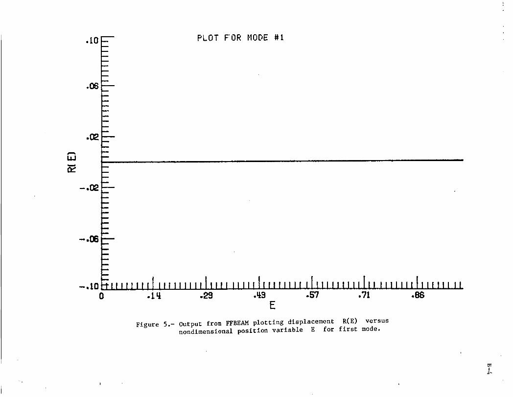
•10-m PLOT FOR NODE #i
.08
.0_
€__i.l_i_.l_ !111 !1 II!• 10 ]0 •111 .L:x3 ._3 .S? .71 .86
E
Figure 5.- Output from FFBEAM plotting displacement R(E) versusnondlmensional position variable E for first mode.
I
I
d
1.5-- PLOT FOR NODE #2
1.0
.5
0 , ,
0 .2 .u_ .6 .8 1.0 1.2E
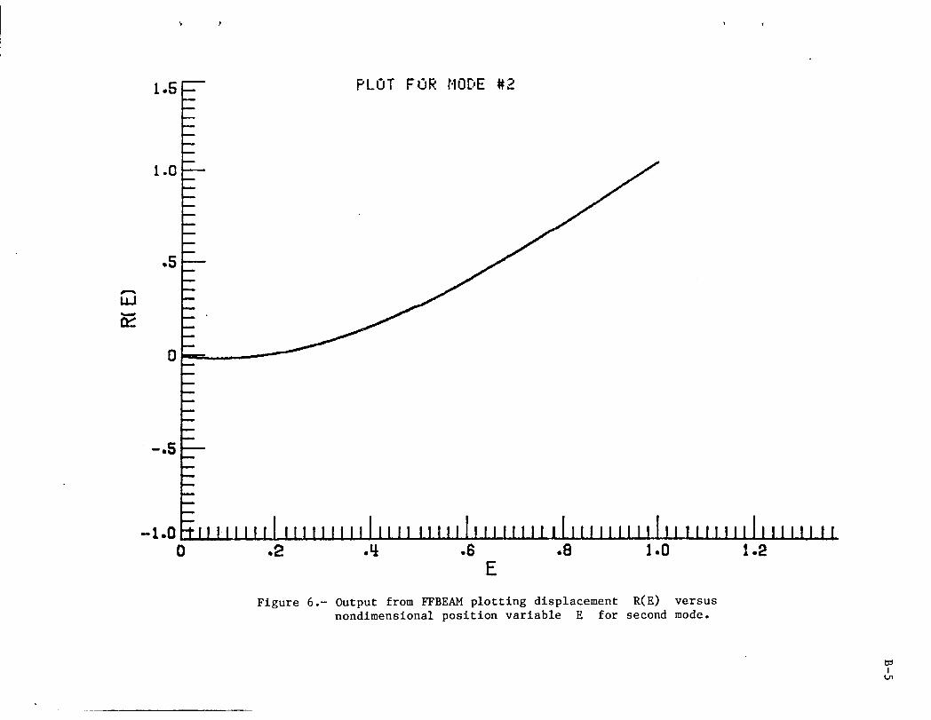
Figure 6,- Output from _BF:.AM plotting displacement R(F:.) versusnondlmenslonal position variable E for second mode.
IL_

Io s _
1.0
.5
0
m..
m
_IS mm
m
m
n
0 .2 -Li .6 .8 I.0 1.2E
Figure 7.- Output from FFBEAM plotting displacement R(E) versusnondimensional position variable E for third mode.
IO_

-- PLOT FOR I,IODE#4
i1
i0 .2 -_ E
Figure 8.- Output from FFBE_t plotting displacement R(E) versusnondimensional position variable E for fourth mode.
!
3 PLOT FOR ttODE #5
2
LLJ
0
-1
.-,9.0 .2 ._ .6 .8 1.0 1.2
E
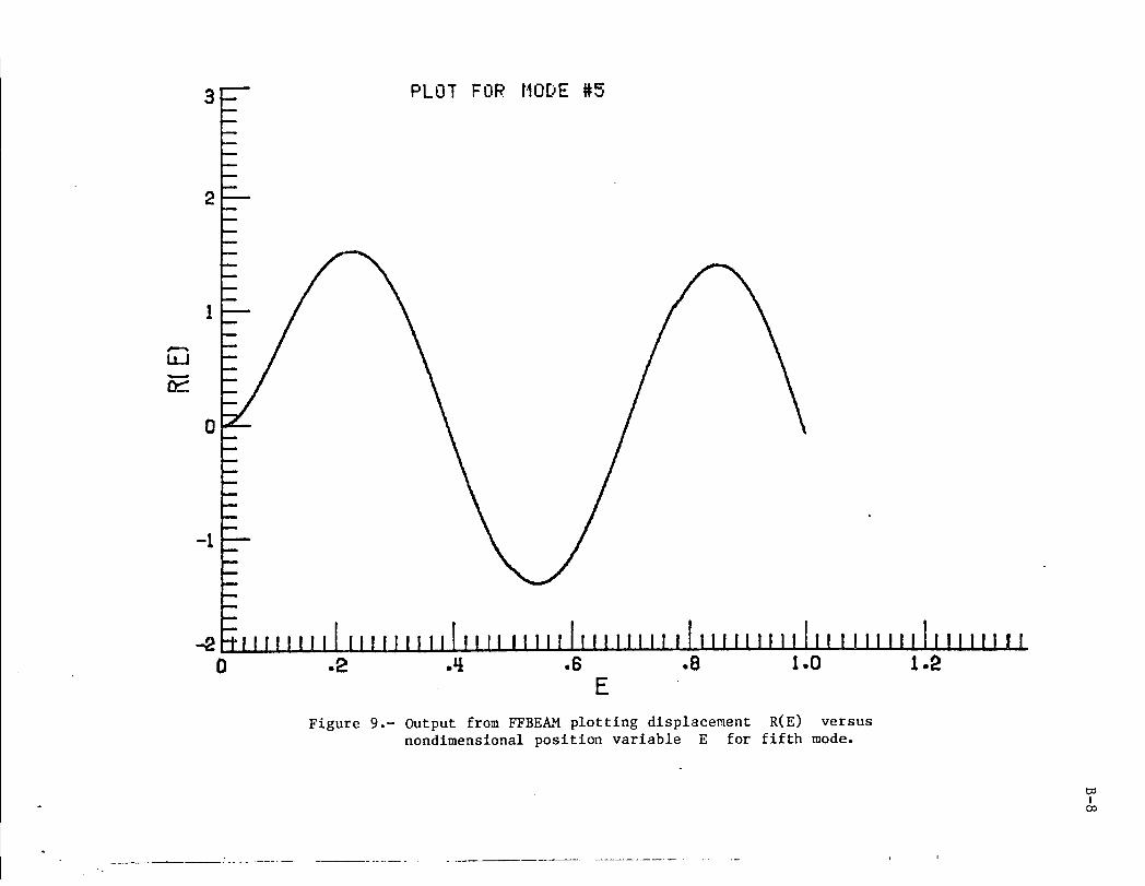
Figure 9.- Output from WBEkH plotting displacement R(E) versusnondtmenstonal position variable E for fifth mode.
Ico
C-I
APPENDIX C.
MACSYMA PROCEDURE
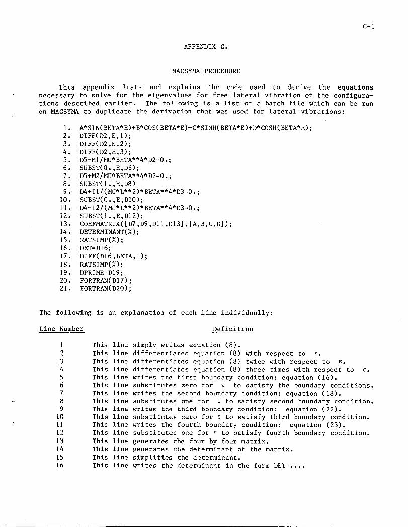
This appendix lists and explains the code used to derive the equations
necessary to solve for the eigenvalues for free lateral vibration of the configura-
tions described earlier. The following is a list of a batch file which can be run
on MACSYMA to duplicate the derivation that was used for lateral vibrations:
I. A*SIN(BETA*E)+B*COS(BETA*E)+C*SINH(BETA*E)+D*COSH(BETA*E);
2. DIFF(D2,E,I);
3. DIFF(D2,E,2);
4. DIFF(D2,E,3);
5. D5-MI/MU*BETA**4*D2=0.;
6. SUBST(O.,E,D6);
7. D5+M2/MU*BETA**4*D2=0.;8. SUBST(I.,E,D8)
9. D4+II/(MU*L**2)*BETA**4*D3=O.;
I0. SUBST(0.,E,DIO);
II. D4-12/(MU*L**2)*BETA**4*D3=O.;
12. SUBST(I.,E,DI2);
13. COEFMATRIX([D7,D9,DII,DI3],[A,B,C,D]);14. DETERMINANT(%);
15. RATSIMP(%);
16. DET=DI6;
17. DIFF(DI6,BETA, I);
18. RATSIMP(%);
19. DPRIME=DI9;
20. FORTRAN(D17);
21. FORTRAN(D20);
The following is an explanation of each line individually:
Line Number Definition
1 This llne simply writes equation (8).
2 This line differentiates equation (8) with respect to _.
3 This line differentiates equation (8) twice with respect to _.
4 This line differentiates equation (8) three times with respect to €.5 This line writes the first boundary condition: equation (16).
6 This line substitutes zero for _ to satisfy the boundary conditions.
7 This llne writes the second boundary condition: equation (18).~ 8 This line substitutes one for _ to satisfy second boundary condition.
9 This line writes the third boundary condition: equation (22).
I0 This line substitutes zero for _ to satisfy third boundary condition.
> II This line writes the fourth boundary condition: equation (23).
12 This line substitutes one for c to satisfy fourth boundary condition.
13 This line generates the four by four matrix.14 This line generates the determinant of the matrix.
15 This line simplifies the determinant.16 This line writes the determinant in the form DET=....
C-2
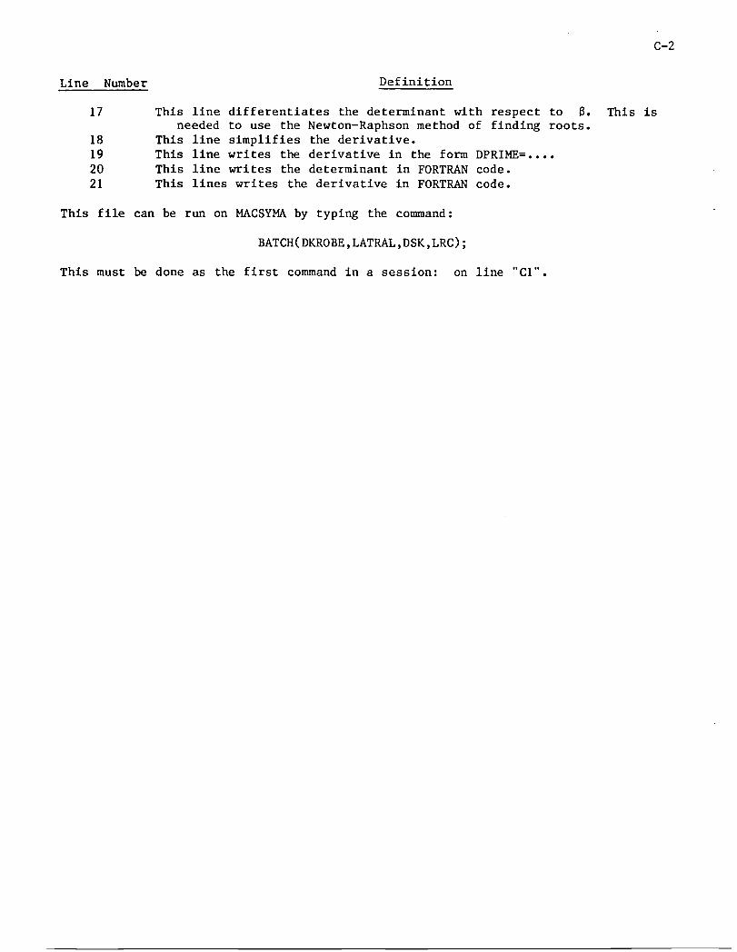
Line Number Definition
17 This line differentiates the determinant with respect to 8. This isneeded to use the Newton-Raphson method of finding roots.
18 This line simplifies the derivative.19 This line writes the derivative in the form DPRIME=....
20 This line writes the determinant in FORTRAN code.
21 This lines writes the derivative in FORTRAN code.
This file can be run on MACSYMA by typing the command:
BATCH(DKROBE,LATRAL,DSK,LRC);
This must be done as the first command in a session: on line '°CI".
D-I
REFERENCES
I. Gorman, Daniel J.: Free Vibration Analysis of Beams and Shafts. John Wiley
and Sons, Inc., 1975.
2. Hansen, H. M.; and Chenea, Paul F.: Mechanics of Vibration. John Wiley and
Sons, Inc., 1952.
3. Thomson, William T.: Mechanical Vibrations. Second Edition;
Prentlce-Hall, Inc., 1953.


UiX.'|E-i
_ x
Figure I.- A differential beam element showing shears and moments resultingfrom displacement V(x,t).
(a) 1. ----..---_ € 2.
(b) (c)
Figure 2.- (a) The beam configuration considered in this paper with
rotating masses mI and m2 at either end. Parts (b) and(c) show the force and moment reactions at the ends.
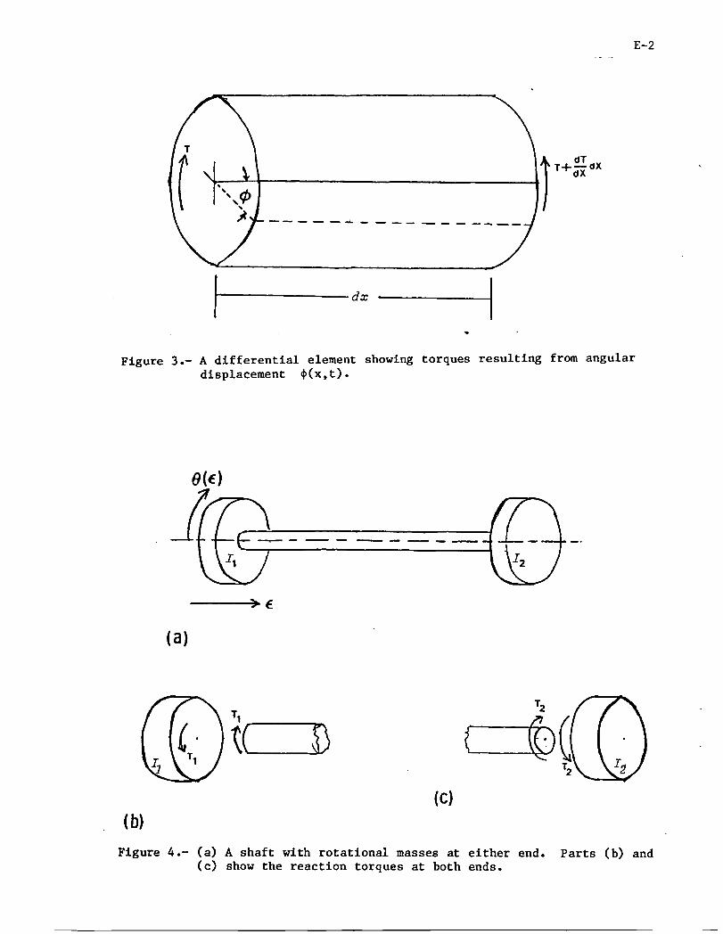
E-2
T dT
I T-l-d-_, clX
/
Figure 3.- A differential element showing torques resulting from angulardisplacement _(x,t).
(a)
(¢)(b)
Figure 4.- (a) A shaft with rotational masses at either end. Parts (b) and(c) show the reaction torques at both ends.

i. Report No. 2. Government Acce_ion No. 3. Recipient'sCatalogNo.NASA TM-84593
I'4. Titleand Subbtle 5. Report Date
Analysis of Lateral and Torsional Vibration Character- May 1984
istics of Beams and Shafts with End Located Rotational 6.PerformingOrganizationCode
Masses 506-57-13-01p, .
7. Author(s) 8. Performing Organ;zation Report No.
Daniel K. Robertson
10. Work Unit No.
9. Performing Organization Name and Address
NASA Langley ResearchCenter t1. Contractor GrantNo.Hampton,VA 23665
13. Type of Report and Period Covered
12. SponsorlngAgency Name and Address Technical Memorandum
National Aeronauticsand Space Administration '14.SponsoringAgencyCodeWashington, DC 20546
15. Supplementary Notes
*Cooperative engineering student from: LJniversity of Cincinnati, Cincinnati, OH
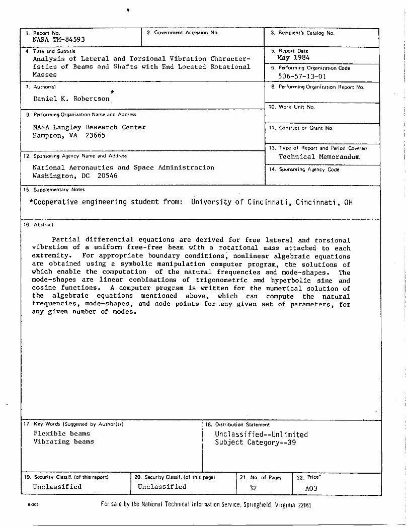
16. Abstract
Partial differential equations are derived for free lateral and torsionalvibration of a uniform free-free beam with a rotational mass attached to each
extremity. For appropriate boundary conditions, nonlinear algebraic equationsare obtained using a symbolic manipulation computer program, the solutions of
which enable the computation of the natural frequencies and mode-shapes. The
mode-shapes are linear combinations of trigonometric and hyperbolic sine andcosine functions. A computer program is written for the numerical solution of
the algebraic equations mentioned above, which can compute the natural
frequencies, mode-shapes, and node points for any given set of parameters, forany given number of modes.
'-- i
17. Key Words (Suggested by Author(s)) 18. Distribution Statement
Flexible beams Unclassified--UnlimitedVibrating beams SubjectCategory--39
19. Security Oassif. (of this re_rt) 20. Security Clas$if. (of this _ge) 21. No. of Pa_s 22. Dice"
Unclassified Unclassified 32 A03
,.3os Forsaleby theNationalTechnicalInformationService,Springfield.Virglma22161