i. mineralogy in the waste isolation pilot plant (wipp
TRANSCRIPT

% cnMqnA phnnpT - w SAND85-0321 Unlimited Release UC-7; Printed September 1985
I .
) Mineralogy in the Waste Isolation Pilot Plant (WIPP) Facility Stratigraphic Horizon
Carol L. Stein
Prepared by Sandia National Laboratories Albuquerque, New Mexico 87185 and Livermore, Callfornia 94550 for the United States Department of Energy under Contract DE-AC04-76DP00789

Issued by Sandia National Laboratories, operated for the United States Department of Energy by Sandia Corporation. NOTICE This report was repared as an account of work sponsored by an agency of the United States Eovernment. Neither the United States Govern- ment nor any agency thereof, nor any of their employees, nor any of their contractors, subcontractors, or their emplo ees, makes any warranty, ex- press or implied, or assumes any legal liagility or responsibility for the accuracy, completeness, or usefulness of any information, apparatus, prod- uct, or process disclosed, or represents that its use would not infringe privately owned rights. Reference herein to any specific commercial product, process, or service by trade name, trademark, manufacturer, or otherwise, does not necessarily constitute or imply its endorsement, recommendation, or favoring by the United States Government, any agency thereof or any of their contractors or subcontractors. The views and opinions expressed here- in do not necessarily state or reflect those of the United States Government, any agency thereof or any of their contractors or subcontractors.
Printed in the United States of America Available from National Technical Information Service U.S. Department of Commerce 5285 Port Royal Road Springfield, VA 22161
NTIS price codes Printed copy: A03 Microfiche copy: A01
2
L
SAND85-0321 Unlimited Release
Printed September 1985
Distribution Category UC - 70
Mineralogy in the Waste Isolation Pilot Plant (WIPP) Facility Stratigraphic Horizon
Carol L. Stein Earth Sciences Division
Sandia National Laboratories Albuquerque, NM 87185
Abstract Forty-six samples were selected for this study from two cores, one extending 50 f t up through the roof of the WIPP facility and the other penetrating 50 f t below the facility floor. These samples, selected from approximately every other foot of core length, represent the major lithologies present in the immediate vicinity of the WIPP facility horizon: “clean” halite, polyhalitic halite, argillaceous halite, and mixed polyhalitic-argillaceous halite. Samples were analyzed for non- NaCl mineralogy by determining weight percents of water- and EDTA-insoluble residues, which were then identified by x-ray diffraction. In general, WIPP halite contains a t most 5 wt% non- NaCl residue. The major mineral constituents are quartz, magnesite, anhydrite, gypsum, polyha- lite, and clays. Results of this study confirm that, in previous descriptions of WIPP core, trace mineral quantities have been visually overestimated by approximately an order of magnitude.
3
_. I_--
Acknowledgments Gautam Sarkar, a graduate student in the Geology
Department a t the University of New Mexico, provided the weight-percent data and the x-ray diffraction analyses of the non-NaC1 mineral residues. His atten- tion to detail throughout both phases of this time- consuming project is gratefully acknowledged. In ad- dition, I thank Klaus Keil of the Institute of Meteoritics, the UNM Geology Department, for his assistance and for many helpful discussions. The manuscript was much improved by the reviews pro- vided by David J. Borns of Division 6331 and by Klaus Keil.
4

Contents Introduction ............................................................................................................................................... Methods ...................................................................................................................................................... Discussion ................................................................................................................................................... Conclusions ................................................................................................................................................. References ................................................................................................................................................... APPENDIX A-Lithologic Logs ............................................................................................................ APPENDIX B-Description of Core Samples Used In This Study .................................................
Figures 1 Map of underground workings showing location of Test Room 4 and location of core
2 Scanning electron micrographs of authigenic quartz crystals found in water- holes .....................................................................................................................................................
insoluble residues from argillaceous halite ((a) . (c)) and thin section photomicrograph of authigenic quartz crystals in recrystallized halite (d) ..............................
densitometry. (b) x.radiography. and (c) conventional dissolution technique .........................
3 Comparison of three different methods of detection of non-NaC1 mineralogy by using surplus core from the WIPP facility horizon: (a) gamma-beam
4 Core RM.l. showing lithologies and amounts of water- and EDTA-insoluble residues ......... 5 Core RM.3. showing lithologies and amounts of water- and EDTA-insoluble residues .........
Tables 1 Weight Percents of Water-Insoluble Residues .............................................................................. 2 X-Ray Diffraction Results from Water-Insoluble Residues ........................................................ 3 Weight Percents of EDTA-Insoluble Residues .............................................................................
5 Statistics on Weight-Percent Data ................................................................................................. 4 X-Ray Diffraction Results from EDTA-Insoluble Residues .......................................................
7 7
16 20 20 21 25
8
13
15 18 19
9 10 11 12 17
5-6
. xL-II-____I ..... L I I I I I . . ...... -.-.. ...___..

Mineralogy (WIPP)
in the Waste Isolation Pilot Plant Facility Stratigraphic Horizon
Introduction As part of the Waste Isolation Pilot Plant (WIPP)
continued geotechnical studies, Sandia National Lab- oratories (SNL) has been charged with the task of producing a detailed characterization of the geologic interval in the immediate vicinity of the WIPP facility. Preliminary work toward this end was begun in 1983 with the Site and Preliminary Design Validation (SPDV) report. The SPDV work includes a compre- hensive mineralogical analysis of 43 rock samples taken at or near the facility horizon. These samples consisted primarily of grab samples taken from the excavation face as mining proceeded, and of selected samples from cores taken from some of the excavated rooms. These samples were processed for their miner- alogical components by a method described in detail in the final SPDV report (Stein, 1983) and summa- rized elsewhere in this report. The end result was a compilation of data that quantitatively describe the non-NaC1 portion of the host halite in the general stratigraphic vicinity of the WIPP facility horizon.
An important conclusion from this set of data is that, up until the time of the SPDV report, visual estimates of the non-NaC1 components were incorrect by as much as an order of magnitude or more. The appearance of the Salado halite can be deceptive, especially when it contains small quantities of very fine-grained, disseminated polyhalite or clay minerals. In summary, from the SPDV work it was learned that WIPP halite contains an average maximum of 5 wt% non-NaC1 mineralogy, except in the cases of units such as anhydrites and clay seams.
This information was, in turn, used to revise some of the ongoing work directed toward predicting long- term creep behavior of the salt around the excavated cavity. However, one shortcoming of the SPDV work concerned the distribution of the sample locations of the analyzed material. It was felt that a more compre- hensive body of data could be obtained by using samples from precisely known locations and could be collected on a more tightly spaced grid. Moreover, the plan for the sampling program that was ultimately adopted also provided for samples to be taken simul- taneously for rock mechanics testing by W. Wawersik
(SNL, Division 1542). Lastly, executing this program provided a set of reference samples for the purpose of making more quantitative visual comparisons of rock samples and a suite of archived core that will remain on file a t the WIPP site for future reference.
Methods The samples selected for this study were taken
primarily from two cores, each - 50 f t long and 4% in. diameter, that were cut in Test Room 4 of the WIPP facility (see map, Figure 1). These cores were cut with a Longyear 38 drill rig, using no liquid lubricant. The cores used in this study are designated RM-1 and RM-3; these were cut vertically upward into the roof, and directly opposite were cut vertically downward, re- spectively. The lithologic logs for these cores are shown in Appendix A.
Samples were chosen from approximately every other foot along the length of the cores. Brief descrip- tions of the portions selected, along with sample num- bers and footages, are listed in Appendix B. Samples were selected from each of the dominant lithologies observed in the core. These are: (1) “clean” halite, (2) polyhalitic halite, (3) argillaceous halite, (4) mixed argillaceous-polyhalitic halite, and (5) anhydrites and clay seams. These samples, each - 6 in. long, were subsequently slabbed; one half was sent to Sandia for processing and analysis; the other remained in Carls- bad for the reference collection.
The technique used to process these samples has been described in detail (Stein, 1983). To summarize briefly, the samples, weighing from -200 g to -1 kg, were crushed to pieces the size of 11 cm3. Weighed amounts of samples were then placed in large beakers of distilled water and stirred continuously until all salt was dissolved. The beakers were then decanted and the remaining residues were collected by filtration onto preweighed Whatman #3 filter papers, allowed to air-dry, and then weighed again. The dry weights of the water-insoluble residues are reported in Table 1. Small fractions of these residues were reserved for x-ray diffraction analysis; results are shown in Table 2. The

remaining portions were further processed by boiling for 4 hr (or longer, as necessary) in 0.25-M EDTA solution. This technique, developed by Bodine and Fernalld (1973), removes all divalent carbonates and sulfates from the water-insoluble residues. Following boiling, the samples were again collected onto sults are shown in Table 4.
preweighed Whatman #3 filter papers, dried, and weighed again to obtain the EDTA-insoluble residue weights (shown as weight percents) in Table 3. As before, where sample material was abundant enough, x-ray diffraction analyses were performed. These re-
Figure 1. Map of underground workings (from Bechtel, 1985) showing location of Test Room 4 and location of core holes. (Note: Cores RM-3 and RM-4 are down; Cores RM-1 and RM-7 (not shown) are up.)
8

~~
Table 1. Weight Percents of Water-Insoluble Residues
Sample Sample Weight of Water- Sample Depth Weight Insoluble Residue Weight 5%
No. (ft) (9) (g) (whole rock)
FH-201 FH-202 FH-203 FH-204 FH-205 FH-206 FH-207 FH-208 FH-209 FH-210 FH-211 FH-212 FH-213 FH-214 FH-215 FH-216 FH-217 FH-218 FH-219 FH-220 FH-221 FH-222 FH-223 FH-224 *core loss zone
**From RM-4 FH-228 FH-229 FH-230 FH-231 FH-232 FH-233 FH-234 FH-235 FH-236 FH-237 FH-238 FH-239 FH-240 FH-241 FH-242 FH-243 FH-244 FH-245 FH-246* FH-247* FH-248* FH-249* *From RM-7
2 4 8.3
10.8 13 15.55 16.9 18.4 19.65 21.5 23 25.1 26 28.25 30.5 31 39.25 41 42.5 44 45.3 47 49.05 4
0.4 2.3 4.75 7.1 7.75 8.15
10.5 12.5 14 16.1 29 34.05 36.9 38.2 43.05 47.2 49.65 51.3 20.05 23.45 25.5 45
2.5 4.7 9
11.3 13.55 15.85 17.45 19.1 20.05 22 23.5 25.7 26.5 28.85 31.05 38 39.85 41.5 43 44.5 45.85 47.5 49.55 4.5**
0.9 2.8 6.75 7.3 8.15 9.1
10.9 12.6 14.45 16.6 29.5 34.5 37.6 38.7 43.55 47.7 50 52.1 20.45 23.95 26 45.65
9
From To
757 482 649 734 715 696 700 670.2 641.3 742.55 700 700 700 751 700 674 535 617.5 676.5 700 743.85 747.5 739.5 385.6
1,000 1.000 1,000
600 900
1,000 1.000 1 ,OoO
200 700 550 600 700
1,000 600 850 300 400
1,000 600
1,000 900
2.76 165.58 13.09 6.83 0.38
27.05 1.41 2.69 1.1
13.86 3.6 5.7 4.57 1.54 0.47 9.93
13.42 10.95 21.13 8.72 4.04 5.94 2.2
235.74
1.425 0.77
169.89 3.27 0.45
13.46 2.87
174.15 12.99 34.68 18.58
184.11 3.04 9.7 6.41
29.03 37.19 8
81.2 0.47 4.96
2.38
0.36 34.35 2.02 0.93 0.05 3.89 0.2 0.4 0.17 1.87 0.51 0.81 0.65 0.205 0.07 1.47 2.51 1.77 3.12 1.245 0.54 0.79 0.3
61.14
0.14 0.08 0.24
28.32 0.36 0.05 1.35 0.29
87.08 1.86 6.31 3.1
26.3 0.3 1.62 0.75 9.68 9.3 0.8
13.53 0.05 0.55

al gg -
rn
+
++
+
+++
E.
+ +
++
+
1 2 P
+
+
0
5 t
++
++
++
++
++
+
8+
++
++
++
+
x
++
+
+
++
++
+
+
++
+
+
++
++
++
+
m
V
F v1
+O
F
++
++
+
+++++
+++++
t
E b:
1b
:t
E
EE
E
+ +++++++
++
z+szg+
+
m
t++
+ +
++
+
++
++
&+
E
10

Table 3. Weight Percents of EDTA-Insoluble Residues
Sample Sample Weight of EDTA- Weight 76 Sample Depth Weight Insoluble Residue (water-insoluble Weight 76
No. (ft) (g) (g) residue) (whole rock) From To
201 202 203 204 205 206 207 209 210 211 212 213 214 215 216 217 218 219 220 221 222 223 224
2 4 8.3
10.8 13 15.55 16.9 19.65 21.5 23 25.1 26 28.25 30.5 31 39.25 41 42.5 44 45.3 47 49.05 4
*Core loss zone **From RM-4
228 229 230 231 232 233 234 235 236 237 238 239 240 241 242 243 244 245 246* 247* 248* 249*
0.4 2.3 4.75 7.1 7.75 8.15
10.5 12.15 14 16.1 29 34.05 36.9 38.2 43.05 47.2 49.65 51.3 20.05 23.45 25.5 45
2.5 4.7 9
11.3 13.55 15.85 17.45 20.05 22 23.5 25.7 26.5 28.85 31.05 38 * 39.85 41.5 43 44.5 45.85 47.5 49.55 4.5**
0.9 2.8 6.75 7.3 8.15 9.1
10.9 12.6 14.45 16.6 29.5 3425 37.6 38.7 43.55 47.7 50 52.1 20.45 23.95 26 45.65
1.025 4 3 3
4 0.53 0.52 4 2.1 4 3.65 0.9
4 4 4 4 4 2.3 4 1.075 4
[nsufficient material
Insufficient material
0.7 0.475 2.075 4.1 3 0.38 3 2.5 3 3 2.9 3 3 2.8 3 3 3 2.7 3 3 0.36 3
0.6 0.02 0.97 1.55
2.11 0.27 0.19 0.6 1.03 2.1 1.935 0.055
2.43 1.5 1.95 2.27 2.61 1.48 2.3 0.46 0.06
0.255 0.15 0.955 0.005 0.21 0.09 0.005 0.65 0.007 0.16 1.29 1.315 0.07 0.02 2.03 0.86 1.76 0.645 1.09 0.08 0.09 1.37
58.54 0.5
32.33 51.67
52.75 50.94 36.54 15 49.05 52.5 53.01 6.11
60.75 37.5 48.75 56.75 65.25 64.35 57.5 42.79 1.5
36.4 31.6 46 0.12 7
23.7 0.17
26 0.23 5.3
44.5 43.8 2.3 0.71
67.7
58.7 23.9 36.3
25 45.7
28.7
2.67
0.21 0.17 0.65 0.48
2.05 0.1 0.06 0.28 0.25 0.425 0.34 0.0125
0.89 0.94 0.86 1.77 0.81 0.35 0.45 0.13 0.92
0.05 0.025 0.11 0.03 0.025 0.01 0.002 0.001 0.2 0.1 2.81 1.36 0.6 0.002 1.1 0.215 5.68 2.22 0.29 0.36 0.0125 0.25
*From core RM-7
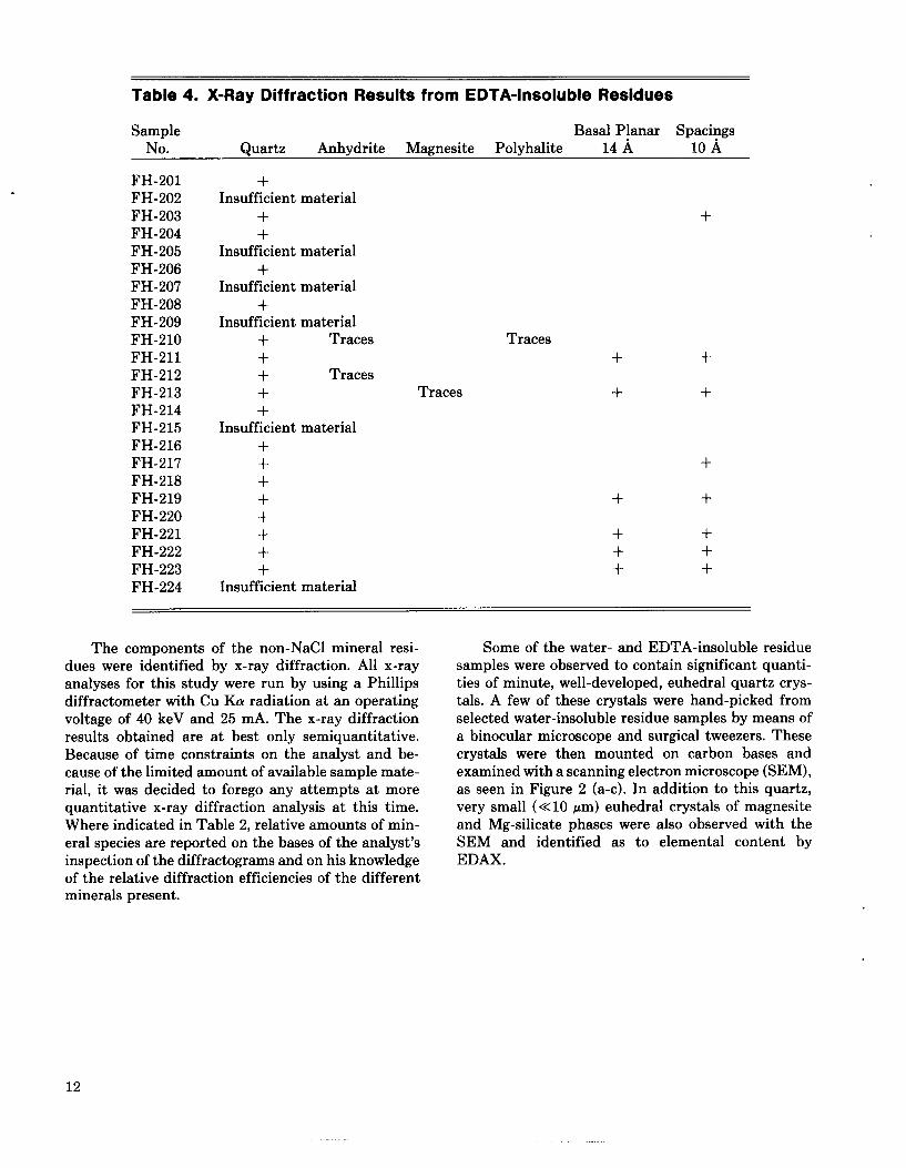
Table 4. X-Ray Diffraction Results from EDTA-Insoluble Residues
Sample Basal Planar Spacings No. Quartz Anhydrite Magnesite Polyhalite 14 A 10 A
FH-201 FH-202 FH-203 FH-204 FH-205 FH-206 FH-207 FH-208 FH-209 FH-210 FH-211 FH-212 FH-213 FH-214 FH-215 FH-216 FH-217 FH-218 FH-219 FH-220 FH-221 FH-222 FH-223 FH-224
+ + + + + + Traces + + Traces + Traces + + + + + + + + +
Insufficient material
Insufficient material
Insufficient material
Insufficient material
Insufficient material
Insufficient material
The components of the non-NaC1 mineral resi- dues were identified by x-ray diffraction. All x-ray analyses for this study were run by using a Phillips diffractometer with Cu Ka radiation at an operating voltage of 40 keV and 25 mA. The x-ray diffraction results obtained are a t best only semiquantitative. Because of time constraints on the analyst and be- cause of the limited amount of available sample mate- rial, it was decided to forego any attempts a t more quantitative x-ray diffraction analysis a t this time. Where indicated in Table 2, relative amounts of min- eral species are reported on the bases of the analyst’s inspection of the diffractograms and on his knowledge of the relative diffraction efficiencies of the different minerals present.
Traces + +
+
+ +
+ + + + + + + + +
Some of the water- and EDTA-insoluble residue samples were observed to contain significant quanti- ties of minute, well-developed, euhedral quartz crys- tals. A few of these crystals were hand-picked from selected water-insoluble residue samples by means of a binocular microscope and surgical tweezers. These crystals were then mounted on carbon bases and examined with a scanning electron microscope (SEM), as seen in Figure 2 (a-c). In addition to this quartz, very small (<<lo pm) euhedral crystals of magnesite and Mg-silicate phases were also observed with the SEM and identified as to elemental content by EDAX.
12

(C )
Figure 2. Scanning electron micrographs of authigenic quartz crystals found in water-insoluble residues from argillaceous halite ((a) - (c)) and thin section photomicrograph of authigenic quartz crystals in recrystallized halite (d).
13

The routine analytical procedure used in this study to determine weight percents of non-NaC1 min- erals, as described above, has two limitations: (1) it is time-consuming and labor-intensive; (2) this process yields weight percents of non-NaC1 minerals as an average for a bulk sample; no information is obtained regarding the spatial distribution of these minerals within that sample. Therefore, two possible alterna- tive techniques, gamma-beam densitometry and x-radiography, were selected on the basis of the fol- lowing criteria:
Rapid data acquisition: relative to the conven- tional analytical method described above, which requires weeks or months to process up to several meters of core, gamma-beam densitometry and x-radiography can analyze the same amount of core in hours or minutes, respectively. Continuous data collection: the information output is obtained from a continuous scan of the core, yielding far more data than integrating bulk mineralogy over a 500-g sample, while si- multaneously showing the desired spatial distri- bution of non-NaC1 components. Sample handling and preparation: whole core was used for x-radiography, and only surface milling in a lathe was required for the gamma beam densitometer. Because both of these tech- niques are nondestructive, the information thus obtained may then be supplemented by thin sections or other mineralogical analyses.
A "trial" halite core (actually, a scrap core of unspecified location within the facility horizon) was selected on the basis of the apparent presence of large
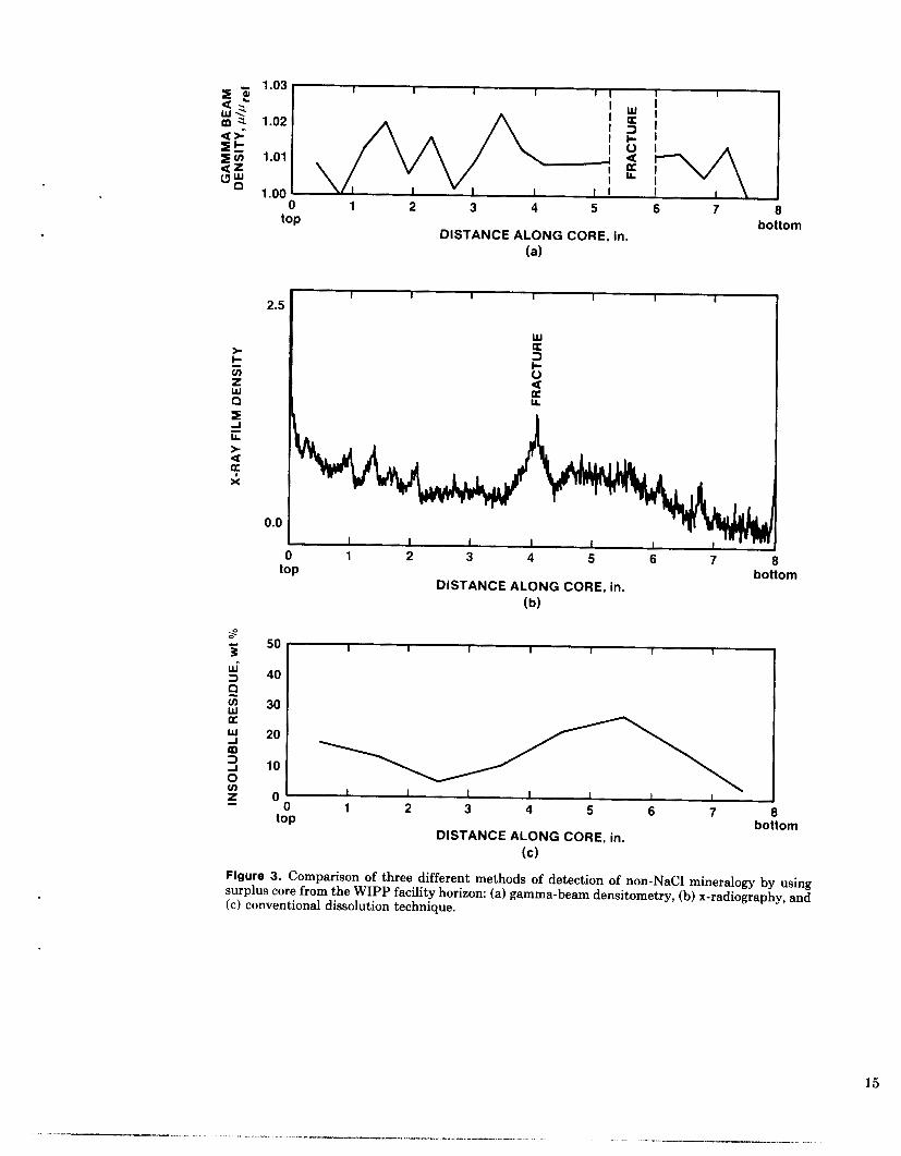
and variable amounts of clays and other mineral im- purities as ascertained by visual inspection. This core was first subjected to scanning by a gamma-beam attenuation system accountable to Sandia's Depart- ment 1510. For further details of this procedure, see Reda and Hadley (1983). This technique uses a C S ' ~ ~ source to produce a photon beam. The attenuation coefficient, p, of this beam through the core material is compared to the measured value for a reference sam- ple of pure salt (praf). The results of the gamma-beam densitometer scan are shown in Figure 3(a).
The same piece of core was also subjected to x- radiography and the film then read by microdensitom- etry; results are shown in Figure 3(b). A large fracture in the core, which showed up on the x-radiograph as a dark line, is offset from the position of the same fracture on the gamma-beam densitometer plot (Fig- ures 3(a) and 3(b)) as a result of the slight rotation of the core from its position in the x-radiographs.
Finally, the core was sliced into - 1-in. pieces and dissolved in distilled water according to the routine procedure. The total dry weight percent of mineral residue is plotted in Figure 3(b) and represents an average value over every 1-in. length of core.
Gamma-beam densitometry appears to be the least suitable of these techniques for detecting mineral impurities in halite core. No obvious correlation exists between the data in Figure 3(a) and in Figure 3(c). The x-radiograph results, however, may be fi t by a smooth curve that reasonably approximates the con- ventional analytical data (Figures 3(b) and 3(c), re- spectively) exclusive of such features as peaks corre- sponding to obvious fractures.
- 1.03 2 2 I I I I I I 1
u.3 m a
10
1.02
1.01
1 .oo 5 6 7 8 1 2 3 4 0
top
0
2.5
0.0
bottom DISTANCE ALONG CORE. in.
(a)
I I I I I I I
w 3 a
a a 6 LL
8 0 ton _-
DISTANCE ALONG CORE, in.
(b)
bottom
50 I I I I I I 1 I
30 4 0 1
bottom
Figure 3. Comparison of three different methods of detection of non-NaC1 mineralogy by using surplus core from the WIPP facility horizon: (a) gamma-beam densitometry, (b) x-radiography, and (c) conventional dissolution technique.
15
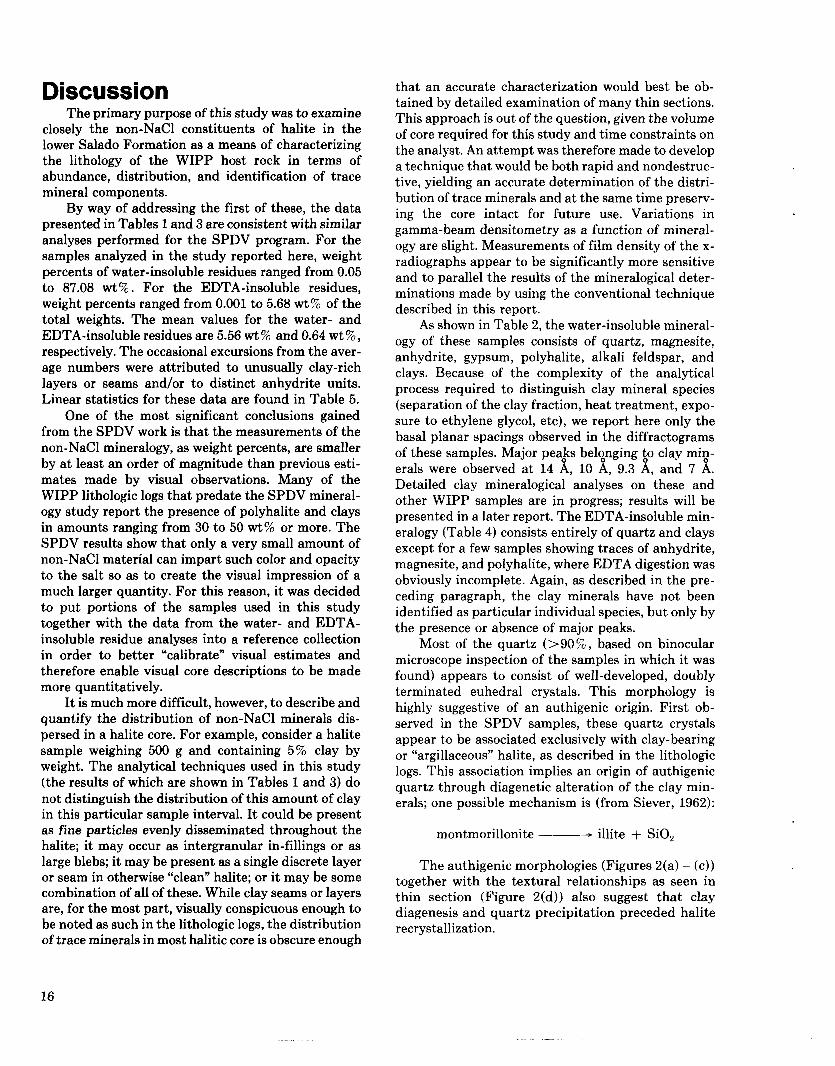
Discussion The primary purpose of this study was to examine
closely the non-NaC1 constituents of halite in the lower Salado Formation as a means of characterizing the lithology of the WIPP host rock in terms of abundance, distribution, and identification of trace mineral components.
By way of addressing the first of these, the data presented in Tables 1 and 3 are consistent with similar analyses performed for the SPDV program. For the samples analyzed in the study reported here, weight percents of water-insoluble residues ranged from 0.05 to 87.08 wt%. For the EDTA-insoluble residues, weight percents ranged from 0.001 to 5.68 wt% of the total weights. The mean values for the water- and EDTA-insoluble residues are 5.56 wt % and 0.64 wt % , respectively. The occasional excursions from the aver- age numbers were attributed to unusually clay-rich layers or seams and/or to distinct anhydrite units. Linear statistics for these data are found in Table 5.
One of the most significant conclusions gained from the SPDV work is that the measurements of the non-NaCl mineralogy, as weight percents, are smaller by at least an order of magnitude than previous esti- mates made by visual observations. Many of the WIPP lithologic logs that predate the SPDV mineral- ogy study report the presence of polyhalite and clays in amounts ranging from 30 to 50 wt% or more. The SPDV results show that only a very small amount of non-NaC1 material can impart such color and opacity to the salt so as to create the visual impression of a much larger quantity. For this reason, it was decided to put portions of the samples used in this study together with the data from the water- and EDTA- insoluble residue analyses into a reference collection in order to better “calibrate” visual estimates and therefore enable visual core descriptions to be made more quantitatively.
It is much more difficult, however, to describe and quantify the distribution of non-NaC1 minerals dis- persed in a halite core. For example, consider a halite sample weighing 500 g and containing 5% clay by weight. The analytical techniques used in this study (the results of which are shown in Tables 1 and 3) do not distinguish the distribution of this amount of clay in this particular sample interval. It could be present as fine particles evenly disseminated throughout the halite; it may occur as intergranular in-fillings or as large blebs; it may be present as a single discrete layer or seam in otherwise “clean” halite; or it may be some combination of all of these. While clay seams or layers are, for the most part, visually conspicuous enough to be noted as such in the lithologic logs, the distribution of trace minerals in most halitic core is obscure enough
that an accurate characterization would best be ob- tained by detailed examination of many thin sections. This approach is out of the question, given the volume of core required for this study and time constraints on the analyst. An attempt was therefore made to develop a technique that would be both rapid and nondestruc- tive, yielding an accurate determination of the distri- bution of trace minerals and at the same time preserv- ing the core intact for future use. Variations in gamma-beam densitometry as a function of mineral- ogy are slight. Measurements of film density of the x- radiographs appear to be significantly more sensitive and to parallel the results of the mineralogical deter- minations made by using the conventional technique described in this report.
As shown in Table 2, the water-insoluble mineral- ogy of these samples consists of quartz, magnesite, anhydrite, gypsum, polyhalite, alkali feldspar, and clays. Because of the complexity of the analytical process required to distinguish clay mineral species (separation of the clay fraction, heat treatment, expo- sure to ethylene glycol, etc), we report here only the basal planar spacings observed in the diffractograms of these samples. Major peabs beloonging $0 clay mig- erals were observed at 14 A, 10 A, 9.3 A, and 7 A. Detailed clay mineralogical analyses on these and other WIPP samples are in progress; results will be presented in a later report. The EDTA-insoluble min- eralogy (Table 4) consists entirely of quartz and clays except for a few samples showing traces of anhydrite, magnesite, and polyhalite, where EDTA digestion was obviously incomplete. Again, as described in the pre- ceding paragraph, the clay minerals have not been identified as particular individual species, but only by the presence or absence of major peaks.
Most of the quartz (>go%, based on binocular microscope inspection of the samples in which it was found) appears to consist of well-developed, doubly terminated euhedral crystals. This morphology is highly suggestive of an authigenic origin. First ob- served in the SPDV samples, these quartz crystals appear to be associated exclusively with clay-bearing or “argillaceous” halite, as described in the lithologic logs. This association implies an origin of authigenic quartz through diagenetic alteration of the clay min- erals; one possible mechanism is (from Siever, 1962):
montmorillonite ---- illite + SiO,
The authigenic morphologies (Figures 2(a) - (c)) together with the textural relationships as seen in thin section (Figure 2(d)) also suggest that clay diagenesis and quartz precipitation preceded halite recrystallization.
16

Table 5. Statistics on Weight-Percent Data
Water-Insoluble Residues
M Mean Std. Dev. Variance Max. X Min. X Range Sum. X Sum. X Square Correction Term Sum. Small X Square Std. Dev. (Mean) Variance (Mean) Normality Test Mean Dev. Third Moment Fourth Moment A Sort B Subl B Sub2 D-Test Statistic
0.45000D + 02 0.55620D + 01 0.14567D + 02 0.21218D+03 0.87080D -to2
0.07030D + 02 0.25029D + 03 0.10728D+05 0.13921D+04 0.93361D +04 0.21715Df01 0.47152D +01
0.50000D - 01
0.75722D $01 0.12952D + 05 0.10072D + 07 0.52571D + 00 0.43342D + 01 0.23399D + 02 0.98294D +01
EDTA-Insoluble Residues
M 0.42000D + 02 Mean 0.63524D + 00 Std. Dev. 0.10344D + 01 Variance 0.10701D + 01 Max. X 0.56600D + 01
Range 0.56790D+01 Sum. X 0.26680D + 02 Sum. X Square 0.60821D+02 Correction Term 0.16948D + 02 Sum. Small X Square 0.43873D + 02 Std. Dev. (Mean) 0.15962D + 00
Normality Test Mean Dev. 0.64367D + 00 Third Moment 0.34221D+01 Fourth Moment 0.16297D+02 A 0.62978D + 00 Sort B Subl 0.32053D+01 B Sub2 0.14935D+02 D-Test Statistic 0.49859D+01
Min. X 0.10000D -02
Variance (Mean) 0.25478D - 01
A simple mass balance calculation (Stein, 1984) clearly indicates that the volume of authigenic quartz present in these halite samples is, on the average, greater by almost two orders of magnitude than that which could have been produced by simple evapora- tion of seawater alone. Further studies of authigenic silicate formation and clay diagenesis are in progress. In addition to the quartz, other authigenic minerals may be present; authigenic feldspars and pyrite and possibly a zeolite have been identified by the author in thin-section, x-ray diffraction, and SEM work on some of the samples in this study. Because these results are preliminary, further details are not included here but will be reported on at a later date.
Figures 4 and 5 illustrate the relationship between weight percents of water- and EDTA-insoluble resi- dues and lithology, as seen in the cores from which these samples were taken. No obvious correlation exists between the non-NaC1 mineralogy and distance from the repository in either the up or down direction. However, these figures indicate that samples from anhydrite-bearing units contain the largest amounts of insoluble residues. Perhaps not surprisingly, sam- ples from the visually designated “clean” halites con- tain the least. Moreover, in Figures 4 and 5, two lines are used for each sample interval to represent weight
percents of water- and EDTA-insoluble residues. The larger the difference between these two lines in any one sample, the greater the relative abundance of the EDTA-soluble component (mainly the sulfate miner- als polyhalite and anhydrite). This is clearly seen in samples such as FH-231, FH-236, and FH-240, taken from distinct anhydrite units in core RM-1 at depths of 7.1 to 7.3 ft, 14 to 14.45 ft, and 36.9 to 37.6 ft, respectively. Conversely, where the difference be- tween each pair of lines is small (for example, FH-239, FH-242, or FH-217 through FH-224), the amounts of water- and EDTA-insoluble residues are nearly equal and thus composed primarily of insoluble silicate residues (quartz and clays) as is typically seen in the zones of argillaceous halite.
It is beyond the scope of this report to discuss the effects of trace mineralogy in WIPP salt on material properties or on creep behavior in rock salt. I t is intended that the data reported here will be used to further modify the structural computations as dis- cussed in Krieg et a1 (1980). This report is intended for use as a supplement to Krieg et a1 (1982) and Krieg (1984), by providing a more complete reference stra- tigraphy that includes detailed analyses of the halite mineralogy.
17

CORE: RM-1 DIRECTION OF DRILLING: VERTICAL UP LOCATION: TEST ROOM 4 (ROOF)
* - - - I I I HALITE ._._._.I 0-0 .1 (...............I
+----I
- I ............... I 0 - 1 +-----I 0 - 10
ANHY DRlTE
POLYHALITIC , 0 - 100 HALITE
HALITE EDTA-INSOLUBLE ARGlLLACEOUS - WATER-INSOLUBLE
SAMPLES ARE FROM RM-7
Figure 4. Core RM-1, showing lithologies and amounts of water- and EDTA-insoluble residues. (RM-7 samples are from another core, taken in the up direction, in close proximity to RM-1 (see Figure l).)
18

CORE: RM-3 DIRECTION OF DRILLING: VERTICAL DOWN LOCATION: TEST ROOM 4 (FLOOR)
WEIGHT PERCENTS
a
10
15
20
a rn m 0 0
- .3 25 r I- n W n
30
35
40.
45 -
50 -
SAMPLING INTERVALS
POLY HALlTlC c----) WATER-INSOLUBLE HALITE EDTA-INSOLUBLE
Figure 5. Core RM-3, showing lithologies and amounts of water- and EDTA-insoluble residues.
19

Conclusions In summary, we report here the quantities, distri-
bution, and mineralogical species of the non-NaC1 components of halite and anydrites in the immediate vicinity (e.g., within 100 vertical feet) of the WIPP facility horizon. These components, as determined by x-ray diffraction, consist of quartz, anhydrite, gyp- sum, magnesite, polyhalite, and clays, with traces of alkali feldspar and possible zeolites. The quartz is primarily authigenic and is probably derived from alteration of the clay minerals. Textural relations indicate that this alteration and precipitation of the authigentic quartz either preceded or perhaps oc- curred simultaneously with halite recrystallization.
The results of the analyses presented herein con- firm previous conclusions regarding discrepancies be- tween visual estimates of mineral impurities in WIPP core and accurate measurements, as obtained by the precedure defined during the SPDV investigation. It has been shown that visual estimates of trace minerals may be too high by as much as an order of magnitude. WIPP salt contains, on the average, t 5 wt% mineral impurities, except in areas of well-defined anhydrite or clay bands or layers. These impurities occur as either finely divided particles dispersed throughout the halite, as intergranular coatings, or as discrete blebs, lenses, laminae, or seams.
The analytical procedure used to produce the re- sults reported here is time-consuming and provides no detailed information as to the distribution of non- NaCl minerals. Alternative methods of sample analysis are being investigated. It appears that x-radiography of halite core is rapid, nondestructive, and accurately reflects mineral impurities in the salt. More work is necessary before this technique can be considered a quantitative tool for this type of examination. Howev- er, the data obtained from the samples analyzed in this study will be used as points for calibration.
References M. W. Bodine, Jr., and T. H. Fernalld, “EDTA
Dissolution of Gypsum, Anhydrite, and Ca-Mg Car- bonates,” J Sed Petrology 43:4, 1152-1156 (1973).
Bechtel National, Inc., for US Dept. of Energy, Quarterly Geotechnical Field Data Report, Section B.0: Test Rooms; WIPP-DOE-199 (May 1985).
R. D. Krieg, H. S. Morgan, and T. 0. Hunter, Second Benchmark Problem for WIPP Structural Computations, SANDSO-1331 (Albuquerque, NM: Sandia National Laboratories, December 1980).
Memo, R. D. Krieg, D. Powers, and R. Price of Sandia National Laboratories (SNL), to D. E. Mun- son of SNL, “Proposed September ’82 WIPP stratig- raphy,” September 20, 1982.
R. D. Krieg, Reference Stratigraphy and Rock Properties for the Waste Isolation Pilot Plant (WIPP) Project, SAND83-1908 (Albuquerque, N M Sandia National Laboratories, January 1984).
Memo, D. C. Reda and G. R. Hadley of SNL to C. L. Stein of SNL, “Salt Core Characterization Via Gamma-Beam Attenuation Measurements,” Septem- ber 9, 1983.
R. Siever, “Silica Solubility, 0” - 200”C, and the Diagenesis of Siliceous Sediments,” J Geol70, pp 127- 150 (1962).
C. L. Stein, Supporting Document 11: “Mineral- ogical Content of Interval Strata”; Supporting Docu- ment 12: “Location and Characterization of Interbed- ded Materials,” in Results of Site Validation Experiments, vol. 2, Supporting Document 5-14. Waste Isolation Pilot Plant, TME 3177 (1983).
C. L. Stein, “Authigenic Quartz in Halite from the Delaware Basin., Southeastern New Mexico (submit- ted to J Geol, August 1984).
20
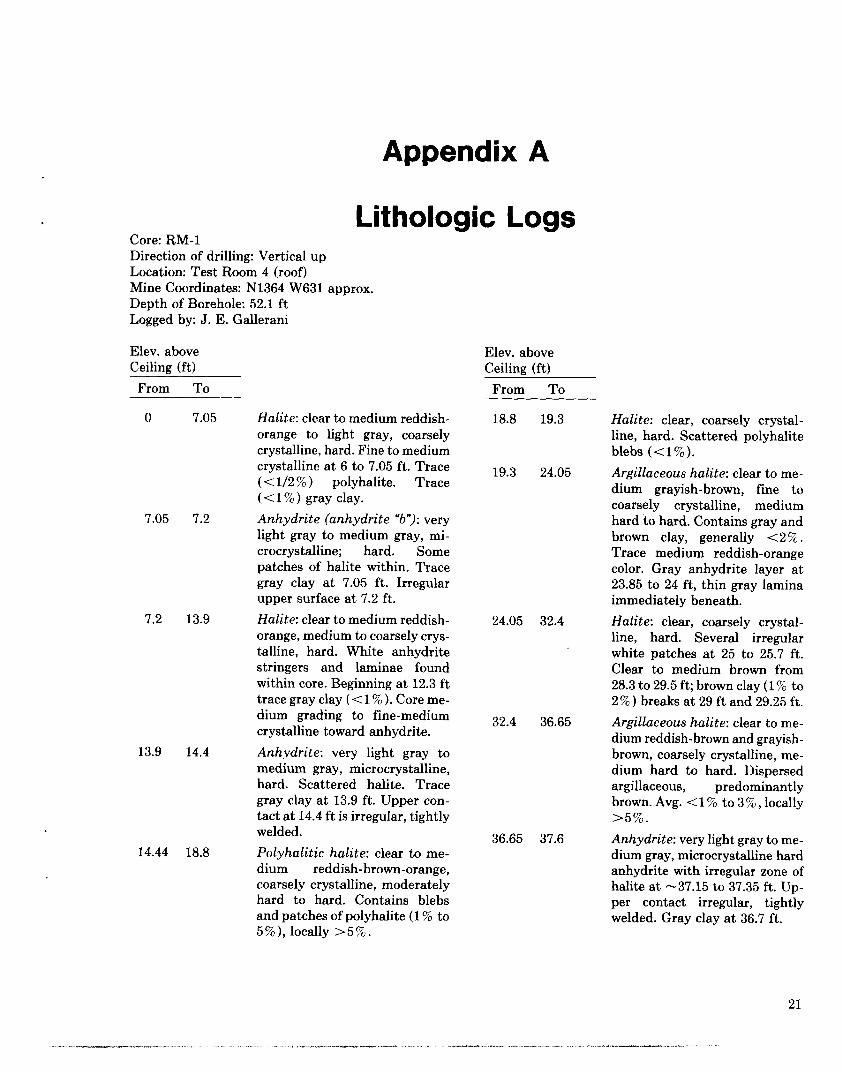
Appendix A
Core: RM-1 Direction of drilling: Vertical up Location: Test Room 4 (roof) Mine Coordinates: N1364 W631 approx. Depth of Borehole: 52.1 f t Logged by: J. E. Gallerani
Elev. above Ceiling (ft)
From To
0
7.05
7.2
13.9
14.44
7.05
7.2
13.9
14.4
18.8
Lithologic Logs
Elev. above Ceiling (ft)
Halite: clear to medium reddish- orange to light gray, coarsely crystalline, hard. Fine to medium crystalline at 6 to 7.05 ft. Trace (< 1/2 5% ) polyhalite. Trace (< 1 % ) gray clay. Anhydrite (anhydrite "b"): very light gray to medium gray, mi- crocrystalline; hard. Some patches of halite within. Trace gray clay at 7.05 ft. Irregular upper surface at 7.2 ft. Halite: clear to medium reddish- orange, medium to coarsely crys- talline, hard. White anhydrite stringers and laminae found within core. Beginning at 12.3 f t trace gray clay ( t l 5% ). Core me- dium grading to fine-medium crystalline toward anhydrite. Anhydrite: very light gray to medium gray, microcrystalline, hard. Scattered halite. Trace gray clay a t 13.9 ft. Upper con- tact a t 14.4 ft is irregular, tightly welded. Polyhalitic halite: clear to me- dium reddish-brown-orange, coarsely crystalline, moderately hard to hard. Contains blebs and patches of polyhalite (1 % to 5%), locally >5%.
18.8 19.3
19.3 24.05
24.05 32.4
32.4 36.65
36.65 37.6
21
From To
Halite: clear, coarsely crystal- line, hard. Scattered polyhalite blebs ( < I % ) .
Argillaceous halite: clear to me- dium grayish-brown, fine to coarsely crystalline, medium hard to hard. Contains gray and brown clay, generally (2%. Trace medium reddish-orange color. Gray anhydrite layer a t 23.85 to 24 ft, thin gray lamina immediately beneath. Halite: clear, coarsely crystal- line, hard. Several irregular white patches at 25 to 25.7 ft. Clear to medium brown from 28.3 to 29.5 ft; brown clay (1 94 to 2% ) breaks at 29 f t and 29.25 ft. Argillaceous halite: clear to me- dium reddish-brown and grayish- brown, coarsely crystalline, me- dium hard to hard. Dispersed argillaceous, predominantly brown. Avg. < 1 '% to 3 '2, , locally >5%. Anhydrite: very light gray to me- dium gray, microcrystalline hard anhydrite with irregular zone of halite a t -37.15 to 37.35 ft. Up- per contact irregular, tightly welded. Gray clay a t 36.7 ft.

Elev. above Ceiling (ft)
From TO
Depth below floor (ft)
From To
37.6
41.8
43.9
48
41.8 Halite: clear to medium reddish- orange, coarsely crystalline, hard. Contains < 1 % polyhalite (dispersed reddish-orange col- or). Core contains highest % po- lyhalite 37.6 to 38.2 ft, scattered white (magnesite) stringers. Argillaceous halite: clear to me- dium brown, coarsely crystalline with some fine, medium hard to hard. Predominantly brown ar- gillaceous 1 % to 3 % , locally up to 5%. Halite: clear to medium brown, fine to coarsely crystalline, me- dium hard. Trace (<l%) argil- laceous and polyhalite. Argillaceous halite: clear to me- dium brown, medium with some fine to coarsely crystalline, me- dium hard to hard. Brown argil- laceous (1% to 5%, avg. 1% to 2%. Clay break at 52.1 ft. 5% to >lo% brown clay at 49.6 to 50.2 ft. Trace ((1 % ) polyhalite.
43.9
48
52.1
Core: RM-4 Direction of drilling: Vertical down
Mine Coordinates: N1362.6 W627.5 Depth of Borehole: 49.5 ft Logged by: J. E. Gallerani
' Location: Test Room 4 (floor)
Depth below floor (ft)
From To
0 2.7 Halite: clear to medium brown, medium to coarsely crystalline, medium hard to hard. Trace (< 1 % ) polyhalite and gray clay.
2.7 6.85 Anhydrite (MB-139): mixture of medium reddish-orange polyha- lite, polyhalitic halite and anhy- drite from 2.7 to 4.2 ft. Coarsely crystalline polyhalitic halite mixed with polyhalitic and mi- crocrystalline anhydrite, approx. 40% to 60%. Grades to higher % anhydrite 4.2 to 5.6 ft. From 5.6 to 6.85 f t is anhydrite. Very light gray to white microcrystalline, laminated anhydrite mixed with 10% to 30% polyhalite and po- lyhalitic halite, hard. Core bro- ken in small pieces at 4.4 to 4.6 ft. Trace gray clay at 6.85 ft.
6.85 10.3 Halite: clear to grayish to me- dium reddish-orange, medium to coarsely crystalline, hard. Gray clay t 1 % , scattered clay breaks. Trace ( t 1 % ) polyhalite.
10.3 14.1 Polyhalitic halite: clear to me- dium reddish-orange, coarsely crystalline, hard. Polyhalite (1% to3%,locally>3%.Scat- tered gray clay breaks to 11.3 ft.
14.1 16.6
16.6 17.7
17.7 19.9
19.9 26.5
Halite: clear to light-gray to me- dium reddish-orange, medium to coarsely crystalline, hard. Trace (< 1% ) gray clay. Parting at 14.3 ft. Scattered clay breaks, < 1 % polyhalitic. Halite: clear with trace of me- dium reddish-orange, coarsely crystalline, hard. Trace ((1% 1 polyhalite. Halite: clear to medium reddish- orange-brown, coarsely crystal- line, hard. Generally t l % poly- halite with local zones to 3%. From 18.4 to 19.6 f t , up to 5% polyhalite. Halite: clear mottled with me- dium reddish-orange and light gray, medium to coarsely crys- talline, hard. Gray clay (1 % . < 1 % polyhalite with local zones to 2%.
22

Depth below floor (ft)
From To
26.5 32.05 Halite: clear to medium reddish- orange-brown, coarsely crystal- line, hard, polyhalitic. Up to 5% polyhalite from -26.5 to 27.5 f t decreasing to avg < 1 % polyha- lite below 29.5 ft. Mostly anhy- drite a t 31.45 to 31.65 ft. Clear halite 30.65 to 31.45 ft.
32.4 39.5
39.5 43
43 50.2
Halite: clear to medium reddish- orange and medium-dark gray, medium to coarsely crystalline, hard. Trace (<l%) gray clay and trace (< 1 % ) scattered poly- halite blebs. Core broken up in very small pieces (gravel-size up to 1 in.) a t 33.4 to 33.75 ft. Halite: clear to medium brown, medium to coarsely crystalline, medium hard to hard. Contains (1% to 3% predominantly brown argillaceous, clay breaks scattered within. Trace (<1/2 % ) polyhalite dispersed throughout. Halite: clear mottled with traces (< 1 % ) of gray clay and medium reddish-orange polyhalite blebs. Medium to coarsely crystalline, hard. Up to 3% gray argilla- ceous at 48.55 to 49.1 ft.
Core: RM-3 Direction of drilling: Vertical down Location: Test Room 4 (floor) Mine Coordinates: N1361 W631 approx. Depth of Borehole: 51.05 ft Logged by: J. E. Gallerani
Depth below floor (ft)
From To
0 0.9 Halite: clear, coarsely crystal- line, hard. Trace (< 1/2 % ) poly- halite blebs and gray clay.
0.9 3 Polyhalitic halite: clear to me- dium reddish-orange, coarsely crystalline hard. < 1 % polyha- lite increasing to -3% to 4% toward lower part of section.
Depth below floor (ft)
From To
3 7.2
7.2 10.45
10.45 14.8
14.8 16.5
16.5 17.9
17.9 19.5
19.5 32
- Anhydrite (MB-139): mixture of 50150% anhydrite and halite from 3 to 3.9 ft. Upper contact is irregular a t 20" to 25" dip. Core hard. From 3.9 to 7.2 ft, very light to medium gray, mi- crocrystalline, hard. Contains halite and polyhalitic halite within. Core loss most probably in this zone. Halite: clear to light gray, me- dium to coarsely crystalline, me- dium hard to hard. Gray argilla- ceous (1%.
Polyhalitic halite: clear to me- dium reddish-orange, coarsely crystalline, hard. Trace < 1/2 76 gray clay, < 1 % to 3 76 polyha- lite. 3/4 in. irregular polyhalite layer a t 14.6 ft. Dark gray clay seam up to 3/4 in. a t -14.8 ft. Halite: clear to light gray, fine to coarsely crystalline, medium hard to hard. Trace ( < 1 5% ) poly- halite and gray clay. Halite: clear with some medium reddish-orange, coarsely crys- talline, hard. < 1 % polyhalite. Polyhalitic halite: clear to me- dium reddish-orange-brown, coarsely crystalline, hard. < 1 % to 5 70 polyhalite, trace ( < 1/2 '36 ) gray clay. Halite: clear, mottled with me- dium reddish-orange, fine to coarsely crystalline, medium hard to hard. Trace ((1% to 2 % ) gray clay and (1% to 2% polyhalite with local zones > 3 % . Clay breaks scattered within core. Polyhalitic halite a t 25.2 to 27.8 ft. Avg 2% to 4 % polyhalite. No clay at 27.8 to 30.1 ft. > lo% polyhalite a t 31.55 to 31.75 ft.
23
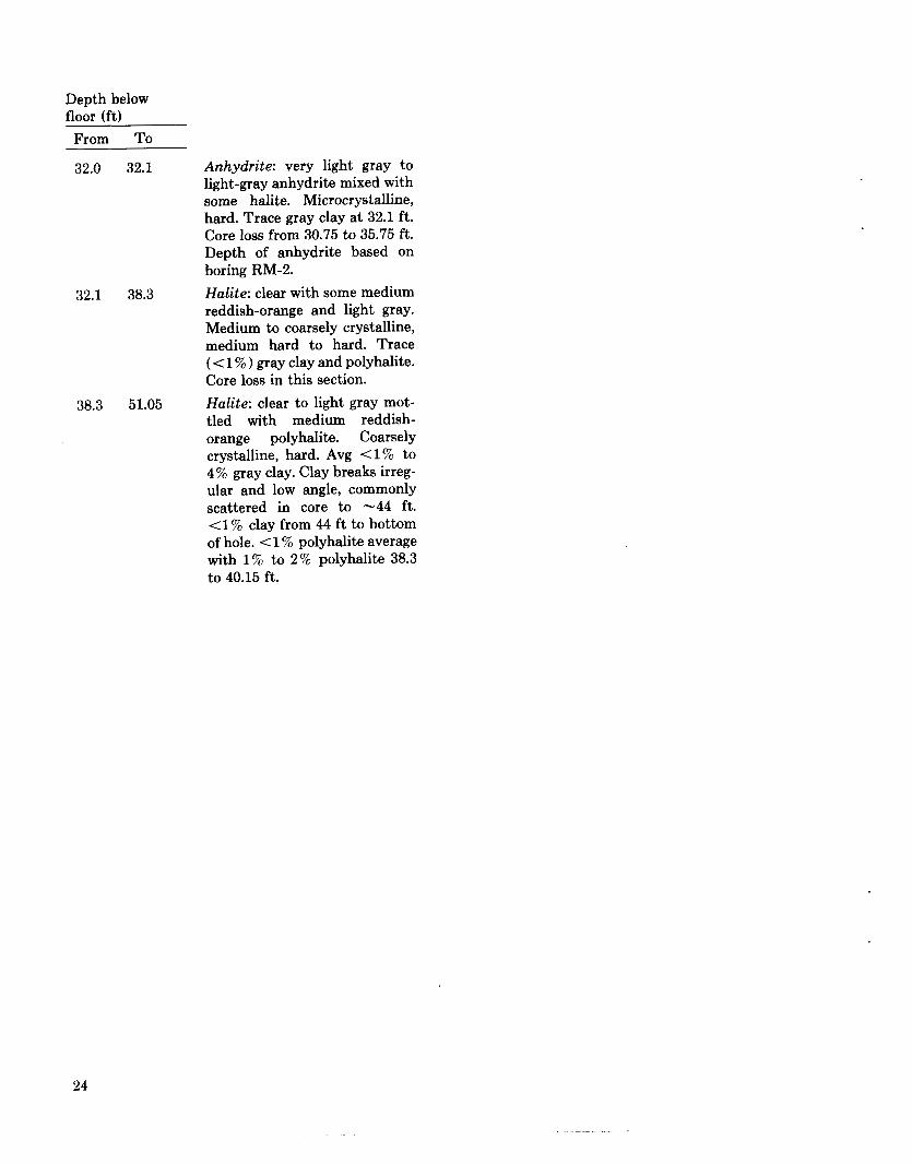
Depth below floor (ft)
From To
32.0 32.1 Anhydrite: very light gray to light-gray anhydrite mixed with some halite. Microcrystalline, hard. Trace gray clay at 32.1 ft. Core loss from 30.75 to 35.75 ft. Depth of anhydrite based on boring RM-2.
32.1 38.3 Halite: clear with some medium reddish-orange and light gray. Medium to coarsely crystalline, medium hard to hard. Trace ( < 1 % ) gray clay and polyhalite. Core loss in this section.
38.3 51.05 Halite: clear to light gray mot- tled with medium reddish- orange polyhalite. Coarsely crystalline, hard. Avg (1% to 4% gray clay. Clay breaks irreg- ular and low angle, commonly scattered in core to -44 ft. (1% clay from 44 f t to bottom of hole. < 1 % polyhalite average with 1 % to 2% polyhalite 38.3 to 40.15 ft.
24
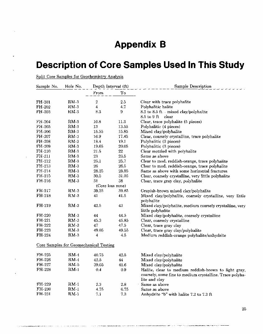
Appendix B
Description of Core Samples Used In This Study Split Core Samples for Geochemistry Analysis
Sample No. Hole No. Depth Interval (ft) Sample Description From To
FH-201 FH-202 FH-203
FH-204 FH-205 FH-206 FH-207 FH-208 FH-209 FH-210
. FH-211 FH-212 FH-213 FH-214 FH-215 FH-216
FH-217 FH-218
FH-219
FH-220 FH-221 FH-222 FH-223 FH-224
RM-3 RM-3 RM-3
RM-3 RM-3 RM-3 RM-3 RM-3 RM-3 RM-3 RM-3 RM-3 RM-3 RM-3 RM-3 RM-3
RM-3 RM-3
RM-3
RM-3 RM-3 RM-3 RM-3 RM-3
2 2.5 4 4.7 8.3 9
10.8 11.3 13 13.55 15.55 15.85 16.9 17.45 18.4 19.1 19.65 20.05 21.5 22 23 23.5 25.1 25.7 26 26.5 28.25 28.85 30.5 31.05 31 38
(Core loss zone) 39.25 39.85 41 41.5
42.5 43
44 44.5 45.3 45.85 47 47.5 49.05 49.55
4 4.5
Core Samples for Geomechanical Testing
FH-225 FH-226 FH-227 FH-228
FH-229
FH-231 FH-230
Clear with trace polyhalite Polyhalitic halite 8.3 to 8.5 f t - mixed claylpolyhalite 8.5 to 9 f t - clear Clear, trace polyhalite (5 pieces) Polyhalitic (4 pieces) Mixed clay/polyhalite Clear, coarsely crystalline, trace polyhalite Polyhalitic (3 pieces) Polyhalitic (3 pieces) Clear mottled with polyhalite Same as above Clear to mod. reddish-orange, trace polyhalite Clear to mod. reddish-orange, trace polyhalite Same as above with some horizontal fractures Clear, coarsely crystalline, very little polyhalite Clear, trace gray clay, polyhalite
Grayish-brown mixed claylpolyhalite Mixed clay/polyhalite, coarsely crystalline, very little polyhalite Mixed clay/polyhalite, medium coarsely crystalline, very little polyhalite Mixed clay/polyhalite, coarsely crystalline Clear, coarsely crystalline Clear, trace gray clay Clear, trace gray clay/polyhalite Medium reddish-orange polyhalitelanhydrite
RM-4 40.75 42.5 Mixed clay/polyhalite RM-4 42.5 44 Mixed clay/polyhalite RM-5 39.05 41.6 Mixed clay/polyhalite RM- 1 0.4 0.9 Halite, clear to medium reddish-brown to light gray,
coarsely, some fine to medium crystalline. Trace polyha- lite and clay
RM-1 2.3 2.8 Same as above RM- 1 4.75 6.75 Same as above RM-1 7.1 7.3 Anhydrite “b” with halite 7.2 to 7.3 f t
25

Sample No. Hole No. Depth Interval (ft) From To
Sample Description
FH-232
FH-233 FH-234 FH-235 FH-236 FH-237 FH-238 FH-239 FH-240 FH-241 FH-242 FH-243 FH-244 FH-245 FH-246 FH-247 FH-248 FH-249
RM- 1
RM-1 RM-1 RM-1 RM-1 RM-1 RM-1 RM-1 RM-1 RM-1 RM-1 RM-1 RM-1 RM- 1 RM-7 RM-7 RM-7 RM-7
7.75
8.15 10.5 12.15 14 16.1 29 34.05 36.9 38.2 43.05 47.2 49.65 51.3 20.05 23.45 25.5 45
8.15
9.1 10.9 12.6 14.45 16.6 29.5 34.5 37.6 38.7 43.55 47.7 50 52.1 20.45 23.95 26 45.65
Halite, clear to medium reddish-orange, medium to coarsely crystalline, white anhydrite stringers Same as above Same as above Same with trace gray clay Anhydrite “a” Polyhalite halite Halite with brown clay, coarsely crystalline Argillaceous halite Anhydrite with some halite Halite with trace polyhalite, magnesite stringers Argillaceous halite Halite, trace polyhalite and clay Argillaceous halite Argillaceous halite, break at 52.1 f t Halite, trace of clay and polyhalite Halite with gray anhydrite, trace clay Halite - clear, coarsely crystalline Halite, trace brown clay, coarsely crystalline
26

DISTRIBUTION:
US Department of Energy, Headquarters (2) Office of Nuclear Waste Management Attn: A. Follett, Project Coordinator (WIPP)
Washington, DC 20545 R. Stein
US Department of Energy (2) Albuquerque Operations Office Attn: G. C. Romatowski
PO Box 5400 Albuquerque, NM 87185
D. G. Jackson, Dir, Public Affairs Div
US Department of Energy (6) Attn: W. R. Cooper
Carlsbad WIPP Project Office (2) A. Hunt, WPO (Carlsbad) (4)
PO Box 3090 Carlsbad, NM 88221
US Department of Energy Carlsbad WIPP Project Office Room 113, Federal Bldg Carlsbad, NM 88220
US Department of Energy, NPO (2) Office of Nuclear Waste Isolation Attn: Jeff 0. Neff
R. Wunderlich 505 King Ave Columbus, OH 43201
US Department of Energy Richland Operations Office Nuclear Fuel Cycle and Production Div Attn: R. E. Gerton PO Box 500 Richland, WA 99352
US Department of Energy Research and Tech Support Div Attn: D .E. Large PO Box E Oak Ridge, T N 37830
US Department of Energy (2) Division of Waste Products Attn: G. H. Daly
J. E. Dieckhoner Mail Stop B-107 Washington, DC 20545
US Department of Energy (2) Idaho Operations Office Nuclear Fuel Cycle Div Attn: R. M. Nelson
J. Whitsett 550 Second St Idaho Falls, ID 83401
US Department of Energy (4) Savannah River Operations Office Waste Management Project Office Attn: J. R. Cove11
D. Fulmer S. Cowan W. J. Brumley
PO Box A Aiken, SC 29801
US Nuclear Regulatory Commission (3) Division of Waste Management Attn: Michael Bell
Hubart Miller Jacob Philip
Mail Stop 697SS Washington, DC 20555
US Nuclear Regulatory Commission HLW Licensing Branch, Materials Section Attn: F. R. Cook MS 905 SS Washington, DC 20555
Battelle Memorial Inst (17) Project Management Div Attn: W. Carbiener, General Manager (3)
S. Basham D. E. Clark S. Goldsmith J. E. Hanley P. Hoffman H. R. Hume H. N. Kalia J. Kircher S. Matthews D. Moak J. Moody G. Raines J. Treadwell ONWI Library
505 King Ave Columbus, OH 43201

DISTRIBUTION (cont):
Battelle Pacific Northwest Labs (4) Attn: D. J. Bradley
J. Relyea R. P. Turcotte R. E. Westerman
Battelle Blvd Richland, WA 99352
Westinghouse Electric Corp (9) Attn: P. Miskimin
V. Likar L. Cole V. DeJong R. Gehrman J. Johnson J. W. Sadler J. E. Stumbaugh Library
PO Box 2078 Carlsbad, NM 88221
Bechtel, Inc (5) Attn: E. Weber
H. Taylor P. Frobenius D. L. Wu W. T. Li
45-11-B34 PO Box 3965 San Francisco, CA 94119
Oak Ridge National Lab (4) Attn: R. E. Blanko
E. Bondietti C. Claiborne G. H. Jenks
PO Box Y Oak Ridge, T N 37830
Oak Ridge National Lab Attn: John 0. Blomeke PO Box X Oak Ridge, T N 37830
US Geological Survey Water Resources Div Attn: John D. Bredehoeft,
345 Middlefield Rd Menlo Park, CA 94025
Western Region Hydrologist
Dr. Karl P. Cohen 928 N California Ave Palo Alto, CA 94303
Stanford University National Acad. of Sci., WIPP Panel Dept. of Geology Attn: Konrad B. Krauskopf, Chairman Palo Alto, CA 94305
Vanderbilt University Dept. of Environmental and
Water Resources Engineering Attn: Frank L. Parker, Vice Chm. Nashville, TN 37235
University of Florida Department of Material Sciences and Engineering Attn: Fred M. Ernsberger,
Gainesville, FL 32611 Adjunct Professor
Johns Hopkins University Department of Earth Sciences Attn: Hans P. Eugster Baltimore, MD 21218
University of New Mexico Department of Geology Attn: Rodney C. Ewing Albuquerque, NM 87131
University of Minnesota Department of Geological Sciences Attn: Charles Fairhurst Minneapolis, MN 55455
University of Texas at Austin Department of Geological Sciences Attn: William R. Muehlberger Austin, TX 78712
D’Arcy A. Shock 233 Virginia Ponca City, OK 74601
National Academy of Sciences Committee on Radioactive Waste Management Attn: John T. Holloway, Senior Staff Officer 2101 Constitution Ave, NW Washington, DC 20418
28
DISTRIBUTION (cont):
Hobbs Public Library Attn: Marcia Lewis, Librarian 509 N. Ship St Hobbs, NM 88248
NM Inst of Mining/Tech Martin Speere Memorial Library Campus St Socorro, NM 87810
New Mexico State Library Attn: Ingrid Vollenhofer PO Box 1629 Santa Fe, NM 87503
University of New Mexico Zimmerman Library Attn: Zanier Vivian Albuquerque, NM 87131
WIPP Public Reading Room Attn: Gwynn Schreiner Atomic Museum, Kirtland AFB, East Albuquerque, NM 87185
WIPP Public Reading Room Carlsbad Municipal Library Attn: Lee Hubbard, Head Librarian 101 S Hallagueno St Carlsbad, NM 88220
Thomas Brannigan Library Attn: Don Dresp, Head Librarian 106 W Hadley St Las Cruces, NM 88001
Roswell Public Library Attn: Nancy Langston 301 N Pennsylvania Ave Roswell, NM 88201
State of New Mexico (2) Environmental Evaluation Group Attn: Robert H. Neill, Dir PO Box 968 Santa Fe. NM 87503
NM Department of Energy and Minerals (2) Attn: Larry Kehoe, Secretary
PO Box 2770 Santa Fe, NM 87501
Kasey LaPlante, Librarian
Argonne National Lab (5) Attn: S . Fried
A. M. Friedman D. Hambeley N. Meldgin M. Steindler
9700 S Cass Ave Argonne, IL 60439
Brookhaven National Lab (2) Attn: P. Colombo, Dept of Applied Sciences
Cal Brewster, Bldg 830 Upton, NY 11973
Brookhaven National Lab Associated Universities, Inc Attn: Paul W. Levy, Senior Scientist Upton, NY 11973
IT Corp (4) Attn: P. Kelsall
R. McKinney A. Moss D. Shukla
Suite 306 2350 Alamo, SE Albuquerque, NM 87106
E. I. Dupont de Nemours Co (4) Attn: N. Bibler
E. J. Hennelly M. J. Plodinec G. G. Wicks
Savannah River Lab Aiken, SC 29801
E. I. Dupont de Nemours Co Attn: R. Baxter Savannah River Plant Aiken, SC 29801
Oak Ridge National Laboratory, Bldg. 2001 Ecological Sciences Information Center Attn: C. S. Fore PO Box X Oak Ridge, T N 37830
Texas A&M University Center of Tectonophysics Attn: John Handin College Station, TX 77840

DISTRIBUTION (cont):
J. F. T. Agapito ASSOC, Inc Attn: Christopher St. John 715 Horizon Dr, Suite 340 Grand Junction, CO 81501
Science Applications, Inc Attn: D. E. Maxwell 2450 Washington Ave, Suite 120 San Leandro, CA 94577
Los Alamos National Lab Attn: B. Erdal, CNC-11 PO Box 1663 Los Alamos, NM 87545
Rockwell International (3) Atomics International Div Attn: M. J. Smith
W. W. Schultz P. Salter
Rockwell Hanford Operations PO Box 800 Richland, WA 99352
US Department of Interior Geological Survey Attn: E. Roedder 959 National Center Reston, VA 22092
Serata Geomechanics Attn: Dr. Shosei Serata 4124 Lakeside Dr Richmond, CA 94806-1941
Systems, Science, and Software (2) Attn: P. Lagus
Box 1620 La Jolla, CA 92038
E. Peterson
Titanium Metals Corp of America Henderson Technical Lab Attn: R. W. Schulz PO Box 2128 Henderson, NV 89015
US Army Engineers (8) Waterways Experiment Station Attn: D. Ainsworth
J. Armstrong J. Boa A. Buck K. Mather C. Pace L. Wakeley D. Walley
PO Box 631 Vicksburg, MS 39180
University of Arizona Department of Mining
Attn: J. J. K. Daemen Tucson, A 2 85721
and Geological Engineering
University of New Mexico Geology Department Attn: D. G. Brookins Albuquerque, NM 87131
Cornel1 University Department of Physics Attn: Dr. R. 0. Pohl Clark Hall Ithaca, NY 14853
Cornel1 University Department of Mechanical
Attn: Dr. Paul R. Dawson 254 Upson Hall Ithaca, NY 14853
and Aerospace Engineering
University of Minnesota Department of Energy
and Materials Science Attn: R. Oriani 151 Amundson Hall 421 Washington Ave, SE Minneapolis, MN 55455
The Pennsylvania State University (2) Materials Research Lab Attn: Della Roy
Rustum Roy University Park, PA 16802
.
30
DISTRIBUTION (cont):
Princeton University Dept of Civil Engineering Attn: George Pinder Princeton, NJ 08540
RE/SPEC, Inc. (4) Attn: P. Gnirk
T. Pfeifle R. Stickney L. Van Sambeek
PO Box 725 Rapid City, SD 57701
RE/SPEC, Inc (2) Attn: S. W. Key
D. B. Blankenship PO Box 14984 Albuquerque, NM 87191
Rockwell International (2) Rocky Flats Plant Attn: W. S. Bennett
Golden. CO 80401 C. E. Wickland
US Geological Survey Special Projects Attn: R. Snyder MS954, Box 25046 Denver Federal Center Denver, CO 80255
US Geological Survey PO Box 26659 Albuquerque, NM 87125
Woodward-Clyde Consultants (2) Library Western Region Attn: Anne T. Harrigan, Librarian
3 Embarcadero Center, Suite 700 San Francisco, CA 94111
Charles Taylor
Institut fur Tieflagerung (3) Attn: K. Kuhn
N. Jockwer H. Gies
Theodor-Heuss-Strasse 4 D-3300 Braunschweig FEDERAL REPUBLIC OF GERMANY
Bundesanstalt fur Geowissenschaften und Rohstoffe Attn: Michael Langer Postfach 510 153 3000 Hannover 51 FEDERAL REPUBLIC OF GERMANY
Hahn-Mietner-Institut fur Kernforschung Attn: Klaus Eckart Maass Glienicker Strasse 100 1000 Berlin 39 FEDERAL REPUBLIC OF GERMANY
Bundesministerium fur Forschung und Technologie Attn: Rolf-Peter Rand1 Postfach 200 706 5300 Bonn 2 FEDERAL REPUBLIC OF GERMANY
Physikalisch-Technische Bundesanstalt Attn: Helmut Rothemeyer Bundesanstalt 100 3300 Braunschweig FEDERAL REPUBLIC OF GERMANY
Kernforschung Karlsruhe (3) Attn: R. Koster
Reinhard Kraemer K. D. Closs
Postfach 3640 7500 Karlsruhe FEDERAL REPUBLIC OF GERMANY
Underground Storage of Radioactive Waste Experimental Programs Attn: Tuen Deboer, Manager PO Box 1 1755 ZG Petten THE NETHERLANDS
Svensk Karnbransleforsorjning AB Project KBS Karn branslesakerhet Attn: Fred Karlsson
10248 Stockholm SWEDEN
BOX 5864
Ontario Hydro Research Lab Attn: Dr. D. K. Mukerjee 800 Kipling Ave Toronto, Ontario MBZ 554 CANADA
31

DISTRIBUTION (cont):
1510 1520 1521 1521 1540 1542 1542 1542 1542 1543 1652 1820 1830 1832 1832 1832 1833 1840 1841 1841 3310 6000 6253 6253 6257 6257 6258 6300 6310 6311 6312 6314 6330 6331 6331 6331 6331 6331 6331 6331
J. W. Nunziato D. J. McCloskey R. D. Krieg H. S. Morgan W. C. Luth B. M. Butcher D. J. Holcomb L. W. Teufel W. R. Wawersik J. L. Krumhansl 0. L. George, Jr. R. E. Whan M. J. Davis W. B. Jones J. W. Munford J. A. Van Den Avyle G. A. Knorovsky R. J. Eagan R. B. Diegle N. R. Sorensen W. D. Burnett E. H. Beckner D. A. Northrop A. R. Sattler R. R. Beasley J. K. Linn B. J. Thorne R. W. Lynch T. 0. Hunter L. w. Scully F. W. Bingham J. R. Tillerson W. D. Weart A. R. Lappin G. E. Barr S. J. Lambert W. B. Miller K. L. Robinson S. E. Shaffer C. L. Stein (11)
6332 A. J. Arguello 6332 R. Beraun 6332 C. L. Christensen 6332 D. M. Ellett 6332 R. V. Matalucci 6332 M. A. Molecke 6332 D. E. Munson 6332 E. J. Nowak 6332 J. C. Stormont 6332 T. M. Torres 6332 L. D. Tyler ( lo) 6332 F. G. Yost 6332 6334 L. H. Brush 7000 R. L. Peurifoy 7100 C. D. Broyles 7110 J. D. Plimpton 7112 C. R. Mehl 7112 G. H. Miller 7116 E. S. Ames 7116 C. W. Cook 7116 S. R. Dolce 7120 T. L. Pace 7125 J. T. McIlmoyle 7125 G. L. Ogle 7130 J . D. Kennedy 7133 C. W. Gulick 7133 R. D. Statler 7135 P. D. Seward 8310 R. W. Rohde 8314 N. R. Moody 8314 M. W. Perra 8314 S. L. Robinson 8315 D. H. Doughty 8315 L. A. West 8430 L. D. Bertholf 8024 M. A. Pound 3141 C. M. Ostrander (5) 3151 W. L. Garner (3) 3154-3 C. H. Dalin (28)
Sandia WIPP Central Files (HLW) (2)
For DOE/TIC (Unlimited Release)
32