i sfinal - dtic
TRANSCRIPT

92174R06APPENDIX AAD-A272 023 EXTA COPY
* PROGRAM MANAGER
RMA CONTAMINATION CLEANUP
I ~ S MAERILCMMAN - CON1;IIT-1 D TO PROTECTION OF THE ENVIRONMENT
SFINAL SAMPLING DESIGN PLAN
HYDRAZINE BLENDING AND STORAGE FACILITYMRC INTERIM RESPONSE ACTION IMPLEMENTATION
II
I Harding Lawson Associates
I
3REQUESTS FOR COPIES OF THIS DOCUAENTSHOULD R E REFERRED TO THE PROGRAM MANAGER
INTE FOR ROCKY MOUNTAIN ARSENALAM'.XRM. PM.1 COMMI,*ERCE CITY, COLORAMDO SC?
Ihi Hardi-ng ias onio Asso c tiate
I
I ROCKY MOUNRsENA i. * co)MME; CITYA COARIA)O 80022-21130

im I m
I Ff•r Approved
REPORT DOCUMENTATION PAGE J V N. Appr.o1ed
Ptluak(eo# .- nq ourdea for rttt coO(Te-lon of 'nformation d eslWrated to averse 1 moua , o efone .nctuaing th tine foe reiewn instruct•o•s. se¢rc-isq eq •tttIn data sources.gatfervtnq and rmasttaunoq the data needed,. anmt io et"rN and te..enn, the cOfleTtlon Of tniormatiot . Send co¢mt $ of retidng th$sbwdom eIt limate ow anv OtheI astaet of th.SColle(tlOio Of •n•rfmatvon. nOU•Io•u •'tagesttrOn tom rfr d rmq tn, oj oen, to Noi$,tOn 'heado tflKuart SevKe 1. O reaO ate for Inormation Ooe0atioo, and Rew,.rt, 215 JeffetonDmaws Hnnwav.~,tUe 12C4. A qt ,nqOt. A .2202- 02. n1 to tt'o Office of Man.ermet Ana guqeo. Pl iwortd R .ul PmOect(07"4-U ). waifngtoa . 0C 20503.
1. AGENCY USE ONLY (Leave blank) 1j2. REPORT DATE 3. REPORT TYPE AND DATES COVERED08/30/89
4 1bMMV6&W 6~ANO STORAG FACILITY, INTERIM REWSPOS ACTION IMPLEMNTATION, S. FUNDING NUMBERSFINAL TASK PLAN
6. AUTHOR(S) 0AAAI5 88 0 0021
7. PERFORMING ORGANIZATION NAME(S) AND ADDRESS(ES) 8. PERFORMING ORGANIZATIONREPORT NUMBER
HARDING LAWSON ASSOCIATES
92274R06
9. SPONSORING iMONITORING AGENCY NAME(S) AND ADDRESS(ES) 10. SPONSORING/ MONITORINGAGENCY REPORT NUMBER
ROCKY MOJNTAIN ARSENAL (CO.). PHR1A
11. SUPPLEMENTARY NOTES
12a. DISTRIBUTION / AVAILABILITY STATEMENT 12b. DISTRIBUTION CODE
"APPROVED FOR PUBLIC RELEASE; DISTRIBUTION IS UNLIMITED
13. ABSTRACT (Maximum 200 worfs)THIS DOCUMENT PRESENTS A SUMMARY OF THE TASK ORDER SCOPE OF WORK AND TECHNICALAPPROACH FOR HYDRAZINE BLENDING AND STORGE FACILITY INTERIM RESPONSE ACTION.THIS PLAN ALSO DESCRIBES PERFORMANCE SPECIFICATIONS, DESIGN OBJECTIVES, ANDOPERATION AND MAINTENANCE REQUIREMENTS FOR THE HYDRAZINE WASTEWATER TREATMENTSYSTEM TO BE IMPLEMENTED AT THE HBSF. THIS TASK PLAN INCLUDES THE FOLLOWINGAPPENDICES: (A) SAMPLING PLAN. (B) QUALITY ASSURANCE PROGRAM PLAN. (C) SAFETYPLAN. (0) RESPONSES TO COMMENTS SUBMITTED BY EPA AND SHELL OIL COMPANY.(APPENDICES A, B, AND C ARE THREE SEPARATE VOLUMES, APPENDIX D IS AT THE END OFTHE TASK PLAN).
14. SUBJECT TERPMS 15. NUMBER OF PAGESIRA N, SAFETY PLAN, OAPP, SAMPLING PLAN
16. PRICE CODE
17. SECURITY CLASSIFICATION 18. SECURITY CLASSiFICATION 19. SECURITY CLASSIFICATION 20. LIMITATION OF ABSTRACT
UN8ULWIED OF THIS PAGE OF ABSTRACT
. , 3 .3";.,a-c -0 1 98 Rev 2.89)

92174R06APPENDIX AEXTRA COPY
TECHNICAL SUPPORT FOR ROCK1 iiUUNTAIN ARSENAL
II Accesion For
NTIS CRA&IDTIC TABUnanr'oucccd [iJust. fc ation .. ............. I............. ...
I Hydrazlne Blending and Storage Facility Py ........................................Interim Response Action Implementation cii. ib .t;o. I
Final Sampling Design Plan Av 0it! 0c,.es
(Appendix A to Task Plan) Dist ocI -August 30, 1989
Contract Number DAAAIS-88-D-0021Task IRA H Phase I (D1livery Order 0003)
I n'rTc QU2 P%= uCED 5Rocky Mountain ArsenalInformaiion Center
I Commerce Ci, olorado°_,
I Harding Lawson Associrtes
PREPARED FOR
IOFFICE OF THE PROGRAM MANAGER FORROCKY MOUNTAIN ARSENAL
THIS DOCUMENT IS INTENDED TO COMPLY WITH THE NATIONAL ENVIRON-MENTAL POLICY ACT OF 1969.
THE INFORMATION AND CONCLUSIONS PRESENTED IN THIS REPORT REPRESENTTHE OFFICIAL POSITION OF THE DEPARTMENT OF THE ARMY UNLESS EXPRESSLYMODIFIED BY A SUBSEQUENT DOCUMENT. THIS REPORT CONSTITUTES THERELEVANT PORTION OF THE ADMINISTRATION RECORD FOR THIS CERCLAI OPERABLE UNIT.

II
I
- TABLE OF CONTENTS
LIST OF TABLES ...................................................... iii
LIST OF FIGURES .. .................................................... iv
1.0 INTRODUCTION ................................................ 1
1.1 TASK SUMMARY ............................................ I
1.1.1 Task Order Scope of Work ................................. 21.1.2 Objectives .. ............................................ 3
1.2 SAMPLING DESIGN PLAN APPROACH .......................... 3
2.0 SAMPLING OBJECTIVES .. .......................................... 5
2.; BENCH/PILOT-SCALE PROGRAM .............................. 5
2.2 START-UP TESTING ........................................... 6
2.3 AIR MONITORING .. .......................................... 6
3.0 SAMPLING LOCATIONS AND FREQUENCY ............................. 7
3.1 BENCH/PILOT-SCALE PROGRAM ............................... 7
3.1.1 Baseline .. .............................................. 73.1.2 W astewater Influent ..................................... 73.1.3 Process Stream .. ......................................... 83.1.4 Final Effluent .. ......................................... 83.1.5 Off-Ga .. ............................................. 8
3.2 START-UP TESTING ......................................... 9
3.2.1 Wastewater Influent ..................................... 93.2.2 Process Stream .. ......................................... 93.2.3 Treated Effluent .. ....................................... 93.2.4 Off-Gas .. ............................................. 103.2.5 Air M onitoring .. ........................................ 10
4.0 ANALYTICAL PARAMETERS AND METHODS .......................... 12
4.1 BASELINE WASTEWATER CHARACTERIZATION .................. 14
4.2 BENCH/PILOT-SCALE WASTEWATER CHARACTERIZATION ......... 14
4.3 START-UP TESTING WASTEWATERCHARACTERIZATION . ....................................... 14
20008,120.10 - IRA-SDP0421082889

I
TABLE OF CONTENTS(Continued)
4.4 FINAL TREATED EFFLUENT WASTEWATER CHARACTERIZATION .. 15
I 5.0 WASTEWATER COLLECTION AND HANDLING PROCEDURES ............ 16
5.1 BULK SAMPLE COLLECTION FOR BENCH/PILOT-SCALE TESTING ... 16
5.2 ANALYTICAL SAMPLE COLLECTION ........................... 17
5.2.1 W 3stewater ............................................ 175.2.2 Off-Gas . ............................................. 19
5.3 SAMPLE CUSTODY . .......................................... 19
3 5.3.1 Chain-or-Custody Form .................................. 20
5.4 PRESERVATION AND SHIPMENT ............................... 21
6.0 QUALITY CONTROL SAMPLES ...................................... 22
6.1 SAMPLE DUPLICATES . ....................................... 22
6.2 TRIP BLANKS . .............................................. 22
1 6.3 FIELD BLANKS .............................................. 22
7.0 LIST OF ACRONYMS AND ABBREVIATIONS .......................... 23
8.0 REFERENCES . ................................................... 27
APENDICES
A SAMPLING PROCEDURES
B FORMS
C RESPONSES TO COMMENTS SUBMITTED BY EPA AND SHELL OIL COMPANY
III
20003,120.10 -.LA-SDP
0421083089
oIosogi

III LIST OF TABLES
ITable No.
3.1 Sample Types, Collection Locations, Number of Samples, Sand Parameters Anticipated for Task IRA H Phase I ................ 7A
5.1 Preservatives, Containers, and Holding Times forTask IRA H Phase I Analyses ................................. 16A
II
20003,120.10 - IRA-SDP0421043089 60i

III LIST OF FIGURES
IFiure No. Pa-e
3.1 Sampling Locations ..................... .................. 7B
5.1 Equipment for Collection of Hydrazine Wastewater ................. 16B
5.2 Schematic of Gas Collection System ............................ 19A
IIIII
I
I
2000.,120-.0 - IRA-SDP0431MA8289 iv

1.0 INTRODUCTION
This Sampling Design Plan has been prepared as Data Requirement A004, a requirement
under Delivery Order 0003 (Task IRA H Phase I) of contract number DAAAIS-88-D-0021
betvesn Harding Lawson Associates (HLA) and its subcontractors and the U.S. Department of
the Army (Army).
This document is submitted as Appendix A to the Task Plan of the Hydrazine Blending and
Storage Facility (HBSF) Interim Response Action (IRA). This plan details procedures that will be
followed in implementing the field phase of the program, including sampling locations and
frequency, analytical parameters and methods, sample handling and collection procedures, and.
quality control samples. Procedures contained herein are consistent with those developed and.
implemented during previous field efforts at Rocky Mountain Arsenal (RMA). In certain
instances, procedutes are modified slightly from previous programs because of different program
objectives or requirements.
1.1 TASK SUMMARY
The HBSF at the RMA near Denver, Colorado, was constructed in 1959 and operated for 23
years from 1959 to 1982. The 10-acre site consists of two tank yards, each completely sur-
rounded by security fencing. The yards are connected by two overhead pipelines.
The HBSF was used as a depot to receive, blend, store, and distribute hydrazine fuels. The
primary operation was blending of anhydrous hydrazine and unsymmetrical dimethylhydrazine.
(UDMH) to produce Aerozine 50. The materials were manufactured elsewhere and were shipped
to RMA for blending. Blending operations were not continuous and occurred in response to
requests by the U.S. Air Force. Other operations at the HBSF included loading and unloading rail
cars and tanker trucks, destruction of off-specification Aerozine 50, and storage of Aerozine 50,
anhydrous hydrazine, monomethyl hydrazine (MMH), monopropellent hydrazine, hydrazine 70,
UDMH, and hydrazine.
20003,20.10 - •RA-SDP0612062889

Hydrazine and UDMH are unstable in the natural environment and rapidly decompose
when exposed to the atmosphere. One of the decomposition products of UDMH is n-nitrosodi-
methylamine (NDMA), a suspected human carcinogen. From January through March 1982, the
U.S. Occupational Safety and Health Administration (OSHA) surveyed the HBSF and detected the
presence of airborne NDMA within the HBSF. In May 1982, RMA ceased operations and closed
the H1BSF to all but safety-essential or emergency-response entries.
On February 1, 1988, a proposed Consent Decree was filed in the case of U.S. v. Shell Oil
Company with the U.S. District Court in Denver, Colorado. A modified version of the Consent
Decree was filed on June 7, 1988. On February 17, 1989, a Federal Facility Agreement (FFA)
that incorporates the provisions of the modified Consent Decree was executed by the U.S. Army,
Shell Oil Company, the U.S. Environmental Protection Agency (EPA), the U.S. Department of the
Interior (DOI), the U.S. Department of Justice (DOJ), and the U.S. Department of Health and
Human Services (DHHS). The FFA specifies a number of IRAs to alleviate certain concerns
prior to the final remedial action. IRA H, Closure of the HBSF, is to be implemented at the
HBSF. The IRA process described in the FFA requires preparation of an Assessment Document,
a Decision Document to include Applicable or Relevant and Appropriate Requirements (ARARs),
and a Draft Implementation Document prior to implementation of the response action. At this
time, the Assessment Document and Decision Document have been completed. Harding Lawson
Associates (HLA) will develop the Draft Implementation Document. This section presents a
summary of the scope of work for the task.
1.1.1 Task Order Score of Work
The HBSF IRA H Task has been separated into two phases, which comprise the decommis-
sioning of the HBSF at RMA. Phase I includes planning, wastewater treatment system selection
and modification (including bench/pilot-scale testing), full-scale system installation, analytical
method development and laboratory method certification, treatment system start-up testing, and
development of a Draft Implementation Document for facility decommissioning. Phase II will
20003,120.10 - IRA-SDP0612082989 2

involve planning, installation of a second wastewater treatment system, operational treatment of
wastewater, reduction and elimination of the facility hazards, dismantling of all above-ground
structures and equipment, disi. )sal of generated solid and liquid waste streams, and preparation
of a Technical Report to document facility decommissioning. The present Task Or'der addresses
only Phase I of IRA H.
1.1.2 Gbiectives
The principal Phase I objectives are to:
- Conduct a bench/pilot-scale testing program to select an appropriate chemical oxidation/ultraviolet (UV) irradiation treatment system for treatment of hydrazine wastewaterstored at the HBSF
- Determine necessary treatment system modifications to achieve the desired dischargeconcentrations for the chemicals of concern in the wastewater
- Develop and certify an analytical method for analysis of NDMA in treated wastewater to
attain the lowest technologically achievable Certified Reporting Limit (CRL)
- Conduct start-up testing of the selected full-scale treatment system at the HBSF
- Gather sufficient process information from the start-up testing to more specificallydefine operational treatment requirements
- Prepare a Draft Implementation Document defining step-by-step procedures fordecommissioning above-ground equipment and treatment of remaining hydrazinewastewater at the HBSF
1.2 SAMPLING DESIGN PLAN APPROACH
This Sampling Design Plan describes sampling and analytical activities to be conducted in
addressing the following two objectives of Phase I of IRA KI
- Select an appropriate chemical oxidation/UV treatment system (Bench/Pilot-ScaleProgram)
- Conduct a successful start-up test of the treatment system at the HBSF (Start-UpOperation)
As part of the treatment system equipment selection process, bench/pilot-scale testing of
equipment at vendor facilities will be conducted with representative wastewater from the HBSF.
Wastewater will be collected from one of the vertical storage tanks at the eastern portion of the
20003,120.10 - IrA-SDP061208289 3

HBSF and will be shipped to vendors for testing. A split sample of this wastewater (baseline
sample) will also be shipped to HLA's contract laboratory for analysis. During berch/pilot-scale
testing at the vendor facilities, samples of process influent, process effluent (process stream), off-
gas, and final effluent (suitable for discharge) will be collected and shipped to HLA's contract
laboratory for arnalysis. Analytical results will be evaluated to measure the effectiveness of the
respective treatment system and will be used as a basis for system selection and design modifica-
tion for application to treatment of wastewater at the HBSF. During bench/pilot-scale testing,
vendors may also choose to conduct in-house analysis of process stream samples.
After a chemical oxidation/UV treatment system is selected and construction is completed
onsite, start-up testing will be conducted at the HBSF with one system sized at one-half the
capacity needed for operational treatment during Phase II of IRA H. During start-up operations,
samples of onsite process influent, process effluent (process stream), off-gas, and final effluent
will be collected. Final effluent that meets discharge requirements will be stored until final
disposal or discharge. Consequently, it will be possible to collect samples of final effluent
directly from the process discharge or from treated effluent storage tanks located adjacent to the
treatment equipment. During start-up testing, samples will be analyzed offsite or onsite in a
mobile laboratory operated by HLA's contract laboratory.
The scope of this Sampling Design Plan includes descriptions of sampling locations and
frequencies, analytical parameters, sample collection and handling procedures, and analytical
procedures for the bench/pilot-scale program and start-up testing.
20003,120.10 - IRA-SDP0612082819 4

2.0 SAMPLING OBJECTIVES
The principal sampling objectives of Phase I of IRA H are separaed i"', ,wo acrivities: (I)
bench/pilot-scale program and (2) start-up .esting.
2.1 BENCH/PILOT-SCALE PROGRAM
The bench/pilot-scale progi.am will provide data on the baseline influent, p'-O, - stream,
final effluent, and off-gas concentrations of various contaminants of concern for evaluation and
design modification of the chemical oxidation/UV treatment system. Baseline sample analyses
will provide (1) an irdication of the nature and concentration of key contaminants and other
analytes requiring treatment and (") an ana.ytical base for evaluating treatment system perfor-
mance. Influent and effluent monitoring are intended to provide an :ndication of treatment
efficiency. Off-gas monitoring will provide data on contaminants that may be released as a result
of the treatment process.
The baseline samples for the bench/pilot-scale-program will be analyzed for other para-
meters, including organochlorine pesticides, semivolatile and volatile organics, and priority
pollutant metals plus iron. In addition to the chemicals of concern discussed above, some of these
parameters have been identified in hydrazine wastewater at the HBSF (Ebasco and others, 1988).
The analytical results will provide HLA and the treatment system vendors an indication of the
overall waste stream constituents to evaluate potential process interferences and help establish any
pre-treatment and post-treatment requirements. Hydrazine fuels and NDMA are anticipated to
be the contaminants tdhAt are mcst difficult to oxidize; however, knowledge of other constituents
in the waste stream and their respective concentrations will allow the treatment system to be
designed to reduce other contaminants of concern in the waste stream to acceptable levels.
Samples of final treated effluent from each treatment system will be analyzed for additional
parameters to evaluate changes that occurred during treatment.
20003,120.10 - IRA-SDP009082889 5

3 2.2 START-UP TESTING
The start-up testing activity will rely on data generated from the bench/pilot-scale testing
U program to refine the chemical oxidation/UV process and to optimize the system. Start-up
testing will involve treatment of an estimated 10,000 gallons of wastewater. During start-up
3 testing, samples of the influent process stream, effluent wastewater, and off-gas from the
treatment process will be analyzed. Analytes for the strrt-up operation include the hydrazine
I fuels, NDMA and purgeable halocarbons and constituents indicated to be problematic by
bench/pilot-scale testing in terms of either treatment interference or requiring treatment for
discharge. Influent samples will be collected to verify previous analyses and characterization.
1 Process stream samples will be collected as needed to assist in optimization of reaction times and
to monitor performance of any intermediate unit processes of the treatment system. The quartz
tubes that enclose the UV bulbs will also be physically examined periodically for scale accumula-
tion. Final effluent samples may be collected directly from the process discharge or from treated
3 effluent storage tanks holding treated wastewater batches scheduled for discharge.
2.3 AIR MONITORING
Air sampling for the presence of hydrazine and NDMA will be conducted to evaluate the
3 integrity of the start-up treatment system and to document personnel exposures. If a treatment
system that employs ozone as a chemical oxidant is selected, air monitoring for ozone will also be
conducted. During the first week of start-up operation, daily samples will be collected and
submitted for analysis on a 24-hour turnaround basis. The 24-hour turnaround is necessary to
evaluate the integrity of the system and to become aware of leaks as soon as possible so that
repairs and/or modifications can be made. Air sampling will also be required whenever opera-
3 tions change such that any increased risk of exposure may be expected.
II
20003,120.10 - IRA-SDP0 6 Og2989 6
I
I
3 3.0 SAMPLING LOCATIONS AND FREQUENCY
This section sets forth the sampling locations and frequencies for the bench/pilot-scale
program and start-up testing activities.
S3.1 BENCH/PILOT-SCALE PROGRAM
Table 3.1 lists sample types, collection locations, the number of samples, and analytical
parameters for the bench/pilot-scale program. Figure 3.1 shows probable sampling locations,ubased on preliminary .aformation provided by the vendors.
3.1.1 Baseline
U Wastewater samples collected from the larger storage tank at the east end of the HBSF site
(US-4) will be sent directly to the contract laboratory for baseline analyses. The objective of the
baseline analyses is to provide an indication of initial concentrations of contaminants for the
bench/pilot-scale program and sta=-up testing. The analyses will constitute a complete scan of
the organics and trace metals of concern. Details of baseline analyses are provided in Section 4.1
* of this document.
3.1.2 Wastewater Influent
Each vendor participating in the bench/pilot-scale program will send one set of untreated
wastewater samples to HLA's contract laboratory. These samples will be collected prior to
treatment from the drums of hydrazine wastewater, which will be shipped from the HBSF to the
i vendors. These samples will be analyzed for hydrazine fuels, NDMA, and purgeable halocarbons.
The objective of the wastewater influent analyses is to provide an indication of initial
3 concentrations of contaminants of concern and to cross-check these concentrations with the
baseline analyses. DetaiLs of wastewater influent analyses are provided in Section 4.2 of this
I document.
1I 203,120.10 - IA-$DP
I

II
Table 3.1: Sample Types, Collection Locations, Number oi Samples,and Parameters Anticipated for Task IRA H Phase I
I__Collection
Tvwe of Samnles L Number of Samples Parameters
Bench/Pilot-Scale Program
Baseline Collected from I per vendor All 0)mid-depth of200,000-gallonTank US-4
Influent Vendor I per vendor Hydrazine fuels,NDMA, EPA 601
Process stream Process discharge Maximum of 5 Hydrazine fuels,per vendor NDMA, EPA 601
Off-gas Treatment system Maximum of 2 Hydrazine fuels,3 vent line per vendor NDMA, EPA 601
Final effluent Discharge outlet I per vendor All(2 )ISar- U TestinM 2 )
Influent Influent holding I per week Hydrazine fuels,tank (10 total) NDMA, EPA 601
Process Stream Process reaction 2 per batch Hydrazine fuels,tank (20 total) NDMA, EPA 601
Off-gas Treatment system I composite per Hydrazine fuels,vent line batch NDMA, EPA 601
(10 total)
Effluent Effluent holding I per discharge Alltank batch
(10 total)
(1) Includes hydrazine fuels, NDMA, purgeable halocarbons (EPA 601), volatiles by GC/MS (EPA8240), semivolatiles by GC/MS (EPA 8270), priority pollutant metals, and pesticides/PCBs3 (EPA 8080).
(2) Final effluent sample parameter list may be modified depending on requirements for dischargeto the RMA sanitary sewer.
(3) Assume batch size is 1,000 gallons, quality control samples will be analyzed on a 2 per 10 basis.
II[ 7A

I A fI:CI wI~ A 3'z
I wZI~1i
fill
I ~NJ
NAJ

II
S 3.1.3 Process Stream
Treated effluent (process stream) wastewater samples will be collected by each vendor and
shipped directly to HLA's contract laboratory for specific analyses. The objective of process
stream analyses is to aid vendors in evaluating the effectiveness of the treatment process for
I different combinations of process and operation parameters. The number of process stream
samples submitted for analyses will vary depending on the process technology and past experience
I of the vendors. However, because of budgetary constraints, each vendor will be limited to a
maximum of five sets of process stream analyses. Details of process stream analyses are provided
in Section 4.2 of this document.
3.1.4 Final f1unI
Final treated effluent samples will be collected on the best-effort batch at the conclusion of
Seach vendor's bench/pilot-scale study. Treated wastewater samples will be analyzed for all of the
parameters included in the baseline analyses to evaluate characteristics and other changes in the
wastewater that occurred during the treatment process.
3.1.5 Off-a
After the process parameters have been optimized by each vendor to achieve treatment
objectives, an off-gas sample will be collected at the effluent end of the ozone destruction
catalyst unit for vendors using ozone treatment. A stream of off-gas from the treatment unit (at
the point of discharge to the atmosphere) will be sampled continuously for the duration of the
final bench/pilot-scale treatability run. Each vendor wil! be allowed a maximum of two off-gas
samples for analyses of hydrazine fuels, NDMA, and purgeable halocarbons. One vendor of three
participating in the bench/pilot-scale program does not use ozone or any other gas-phase oxidant.
Consequently, it is anticipated that this vendor's system will not produce 'an off-gas stream and
will not be sampled at this time. The objective of the off-gas analyses s to evaluate compliance
with off-gas discharge requirements. Results from off-gas analyses will also aid in performing
necessary material and energy balances on the reactor.
20,120.IO0 - IRA-SDP060"82"9o

I
3.2 START-UP TESTING
Table 3.1 lists the sample types, collection locations, the number of samples, and analytical
parameters for start-up testing. Figure 3.1 shows probable sampling location based on prelim-
inary design criteria. Because the design has not been finalized, the locatiom presented inr Figure 3.1 are probable options. Actual sampling locations for start-up testing will be based on
the final design. During start-up testing, process operational parameters including pH, tempera-
ture, oxidant dose and concentration conductivity, turbidity, and flow rate will be monitored
periodically.
3.2.1 Wastewater fnfluent
During start-up testing, wastewater from the vertical tanks at the eastern portion of the
HBSF will be pumped once a week to an influent holding tank before being treated by the
chemical oxidation/UV system. Assuming a 1000-gallon batch capacity of the wastewater treat-
ment unit, a 5-day period (one work week) will be required to treat the wasuvater pumped into
the holding tank. Because the dissolved concentrations of organics were homogeneously dis-
tributed in the storage tanks at the HBSF (Ebasco and others, 1988), only one set of samples per
week will be collected and analyzed from the wastewater influent holding Lank. Details of the
analyses to be performed for wastewater influent are provided in Section 43 of this document.
3.2.2 Stream
One or two sets of samples per batch of treated wastewater will be sent for analyses to
HLA's contract laboratory. These samples will be collected at the end of each batch treatment
period and before pumping to the effluent storage tanks. Details of the analyses to be performed
on the process stream are provided in Section 4.3 of this document.
3.2.3 Treated Effluent
It is anticipated that treated effluent will be stored in three holding tanks before discharge
to the RMA sanitary sewer. When the first tank is full, the second tank will be connected
20003,120.10 - MIA-SDPosoo60s8" 9

I
1II
directly to the effluent stream of the treatment unit, and the third tank will be used for emer-
gency storage. Before discharge of treated effluent from the holding tanks to the RMA sanitary
5 sewer, one set of samples per batch or per holding tank will be collected and analyzed to comply
with requirements for discharge to the RMA sanitary sewer. Details of the analyses to be per-
U formed on treated effluents are provided in Section 4.4 of this document.
3.2.4 Off-G
If a wastewater treatment unit employing ozone is selected for start-up operations, off-gas
5 samples will be collected during the entire treatment period for each batch of wastewater treated,
and a composite of the sample collected will be analyzed for compliance with any applicable off-
I gas discharge requirements. The off-gas sample will be collected after the ozone destruction
catalyst unit at the point of discharge to the atmosphere. If a wastewater treatment unit employ-
ing hydrogen peroxide is selected for start-up operations, the potential for off-gasing from this
g unit will be evaluated and appropriate action taken to comply with applicable off-gas discharge
requirements.
3.2.5 AirMoniig
Permanent air-monitoring stations for real-time detection of hydrazine fuels and ozone will
be installed in the area surrounding the treatment plant. HNu photoionization detectors will be
utilized for detection of volatile organics while personnel are onsite. The permanent stations will
monitor air quality during hours of operation of the treatment fzcility. The real-time monitors
will include a colorimeter detection system based on the change in light reflection from a
hydrazine or ozone reactive paper strip. Any time the monstoring equipment indicates an
increase in ambient air concentrations of hydrazine or ozone a_'ove predetermined concentrations,
all personnel will be instructed to immediately exit the area.
As there is currently no commercial means of real-time detection of NDMA, two area
samples will be collected each day for NDMA analysis. Standard personal air-sampling pumpsII 20003,120.10 - MRA-SDP
0 os"239ug 10
I

II
1 will be used to draw ambient air into the NDMA sampling cartridge. Pumps will be calibrated
each day before sampling begins.
NDMA air samples will be sent by overnight courier to the Thermedics Analytical Laborat-
ory for analysis. If nondetectable concentrations of NDMA are reported in five consecutive
I samples, the use of supplied air by personnel at the site will no longer be mandatory.
During the remainder of start-up operation, two samples per day, two days per week, will
I be collected and submitted to Thermedics Analytical Laboratory for NDMA analysis. A 24-hour
turnarov d time will be requested.
Air-monitoring samples for hydrazine fuels will be collected concurrently with samples for
NDMA and will be analyzed according to National Institute for Occupational Safety and Health
(NIOSH) methods. These methods involve trapping hydrazine fuels in silica gel solid sorbent
tubes. Two area samples will be collected each day as long as daily NDMA samples are collected.
Pumps will be calibrated both before and after sampling. Samples will be submitted to Hagar
I Laboratories in Englewood, Colorado, for 24-hour turnaround analysis.
The NIOSH method will serve as a verification of the real-time hydrazine monitor. When
daily hydrazine samples are no longer necessary, two hydrazine samples will be collected per day,
two days per week, for the remainder of start-up operations.
I In addition to the real-time and nonreal-time air monitoring for hydrazine, NDMA, and
ozone, all personnel at the plant will be required to wear a personal hydrazine passive dosimeter
at all times. A passive dosimeter will change color if the ambient air concentration of hydrazine
is greater than a predetermined concentration. Dosimeters will be available from commercial
sources and/or the Naval Research Laboratory.
20003,120.10 - IRA-$DP
/
III 4.0 ANALYTICAL PARAMETERS AND METHODS
I During the bench/pilot-scale program and start-up testing, wastewater samples will be
analyzed to evaluate treatment technology efficiency and to provide water-quality data for
SI assessing discharge of treated effluent wastewater. Wastewater samples will be analyzed for
organic and inorganic parameters, including hydrazine fuels, NDMA, purgeable halocarbons,
volatile organics, semivolatile organics, pesticides/PCBs, and metals. During the bench/pilot-
scale program, four phases of analytical testing will be conducted: (1) baseline wastewater
i characterization prior to bench/pilot-scale testing, (2) influent, effluent, process stream, and off-
gas characterization during bench/pilot-scale testing, (3) influent, effluent, process stream, and
I off-gas characterization during start-up testing of the treatment system, and (4) final treated
effluent from the start-up testing treatment system prior to disposal to the RMA sanitary sewer.
Analysis of wastewater samples collected during the first three phases of analytical testing
will be conducted utilizing standard EPA methods. During the fourth phase of testing, waste-
water samples will be analyzed by laboratory-certified methods in accordance with the U.S.
j Army Toxic and Hazardous Materials Agency (USATHAMA) certification protocols
(USATHAMA, 1987.)
Currently, a standard analytical method that can achieve the proposed detection limit for
NDMA in water is not available. Consequently, method development for analysis of low-
t concentration samples for NDMA will be conducted by the Illinois Institute of Technology
Research Institute (IITRI). I1TRI has developed a method for analyses of NDMA using a
I modified EPA Method 607. IITRI reports method detection limits for NDMA utilizing the
modified method at 20 parts per trillion (ppt). IITRI will be required to provide documentation
of the method to PMRMA for evaluation of technical soundness, completeness, and method
certification approval prior to the completion of start-up testing.
Hydrazine fuels, including hydrazine, UDMH, and MMH will be analyzed by gas
chromatography/flame ionization detector (GC/FID) for high-concentration samples (greater than
200.0310.10 - MA-SDPo0o6002U9 12

I part per million [ppm]). Low-concentration samples (less than 1 ppm) will be analyzed for
hydrazine fuels by gas chromatography/nitrogen-phosphorous detector (GC/NPD). Purgeable
halocarbons will be analyzed by EPA Method 601. Volatile organics will be analyzed by gas
chromatography/mass spectrometry (GC/MS) by EPA Method 8240. Semivolatiles will be
analyzed by GC/MS by EPA Method 3270, and pesticides/PCBs will be analyzed by GC/electron
capture detector (ECD) by EPA Method 8080. Metals will be analyzed by the EPA 200 series
methods.
Target reporting limits (TRLs) for the target parameters analyzed by laboratory certified
metA.ods will be provided by PMRMA. The TRL will be specified by PMRMA based on the
lowest technologically attainable method detection limits and regulating environmental quality
criteria. Currently, TRLs have been established for NDMA (Task Order IRA H Phase I,
December 22, 1988) and the three hydrazine fuels (PMRMA, September 1988). These TRLs are:
Compound "rUg
NDMA 1.4 parts per trillion (ppt)Hydrazine 2.5 parts per billion (ppb)UDMH 20 ppbMMH 25 ppb
HLA's contract laboratory, which will analyze samples of the final treated effluent from
start-up testing, must demonstrate proficiency in conducting method analyses of target parameters
discussed previously in accordance with the USATHAMA certification process. During the
certification process, a certified reporting limit (CRL) for each of these target parameters will be
calculated. The calculated CRLs will then be sumbitted to PMRMA for review and approval.
CRLs for actual wastewater samples are sample- and matrix-dependent and may not always be
achievable. Actual reporting limits for wastewater samples will be reported by the laboratory.
Method detection limits for target parameters not analyzed by laboratory-certified methods
during the first three phases of analytical testing will be consistent with the method detection
limits stated for the specified standard EPA methods.
20003,120.1o - M.A-SVPoso9No289 13

II
J [4.1 BASELINE WASTEWATER CHARACTERIZATION
Prior to conducting bench/pilot-scale treatment testing, wastewater samples will be
analyzed for organic and inorganic parameters to provide baseline characterization. The
following parameters will be analyzed during this phase of analytical testing.
- Hydrazine fuels (hydrazine, UDMH, and MMH) by both GC/FID and G-C/NPD
- NDMA by modified EPA Method 607 (method provided by IMIRI)
- Purgeable halocarbons by EPA Method 601
- Priority pollutant metals plus iron
- Organochlorine pesticides and polychlorinated biphenyls (PCBs) by EPA Method 8080
- Base neutral/acid extractable organics (BNAs) by EPA Method 8270, plus tentativelyidentified compounds
- Volatile organic compounds by EPA Method 8240, plus up to 10 tentatively identifiedcompounds
4.2 BENCH/PILOT-SCALE WASTEWATER CHARACTERIZATION
During the bench/pilot-scale testing program, influent, process stream, and off-gas samples
will be analyzed for the following target parameters:
- Hydrazine fuels (hydrazine, MMH, and UDMH) by GC/FID and GC/NPD
- NDMA by modified EPA Method 607 (method provided by IITRI)
- Purgeable halocarbons by EPA Method 601
The best-effort batch of final treated effluent at the conclusion of each vendor's bench/
pilot-scale study will be analyzed for parameters included in the baseline wastewater characteri-
zation analyses.
4.3 START-UP TESTING WASTEWATER CHARACTERIZATION
During start-up testing, influent, effluent, process stream, and off-gas samples will be
analyzed for the following target parameters:
- Hydrazine fuels (hydrazine, UDMH, MMH, and UDMH) by GC/FID and GC/NPD
- NDMA by modified EPA Method 607 (method provided by IITRI)
30M,120.10 - MA-SDPOMsJ289 14

- Purgeable halocarbons by EPA Method 601
4.4 FINAL TREATED EFFLUENT WASTEWATER CHARACTERIZATION
Final treated effluent wastewater samples from the start-up testing treatment system will be
analyzed for parameters required for discharge to the RMA sanitary sewer. Target parameters
will be analyzed during this phase by laboratory-certified methods in accordance with
USATHAMA certification protocols prior to effluent discharge to the RMA sanitary sewer. At a
minimum, samples will be analyzed for the following target parameters:
- Hydrazine fuels (hydrazine, UDMH, and MMH) by GC/NPD
- NDMA by modified EPA Method 607 (method provided by I=TRI)
- Purgeable halocarbons by EPA Method 601
Based on a decision regarding final criteria for discharge to the RMA sanitary sewer, additional
target parameters may be added to comply with the final criteria. At this time, the treated
effluent parameters for bench/pilot-scale studies are to be the same as the influent parameters
described in Section 4.1.
20003,120.10 - ILA-SDP060M"90 15

!I
5.0 WASTEWATER COLLECTION AND HANDLING PROCEDURES
Based on the HBSF site reconnaissance conducted by HLA field personnel on
April 25, 1989, the wastewater will be collected through a manhole port on the south rim at the
top of the 200,000-gallon tank (US-4) on the eastern portion of the HBSF. The wastewater will
be collected at the tank's mid-level through the manhole opening. Sample preservatives,
containers, and holding times are listed in Table 5.1. Table 3.1 details the approximate number
and types of samples to be collected.
5.1 BULK SAMPLE COLLECTION FOR BENCH/PILOT-SCALE TESTING
The equipment necessary to collect the volume of wastewater required to be shipped to
vendors for bench/pilot-scale testing is described in the following paragraphs.
A 14-foot flatbed truck with a hydraulic lift tailgate will be used to contain 12 new U.S.
Department of Transporation (DOT) approved 17-E stainless steel (304) drums. The drums will
be placed on a 33mm-thick Hypalon liner draped over railroad ties s~tuated in a rectangular array
in the truck bed, which will provide a temporary containment system for potentially spilled
liquids. A mechanical pump will be used to remove any wastewater spilled during collection
activitics. Spilled wastewater will be placed in additional stainless steel barrels not used for
shipment of wastewater for bench/pilot-scale testing. The drums will be stored at the RMA
drum storage area and will be disposed during the decommissioning phase of this Task.
The equipment used to transfer the wastewater from the tank to the drums is shown in
Figure 5.1. A nonmetal mechanical pump will be adapted to fit I-inch PVC flexible tubing. As
shown in Figure 5.1, 15 feet of PVC tubing will be connected to the inlet side of the pump. The
end of the PVC tube that will be lowered into the tank will be fitted with a check (ball float)
foot valve. Approximately 45 feet of PVC tube will be attached to the discharge side of the
pump. The end of the PVC tube that will be used to fill the 55-gallon drums will have a double
bail valve attached so that wastewater flow may be reduced to fill the sample bottles. Sample
bottles will be placed on too of a drum while being filled. Any filtering required for the
20003,120.10 - IRA-SDPo~soso~ 16
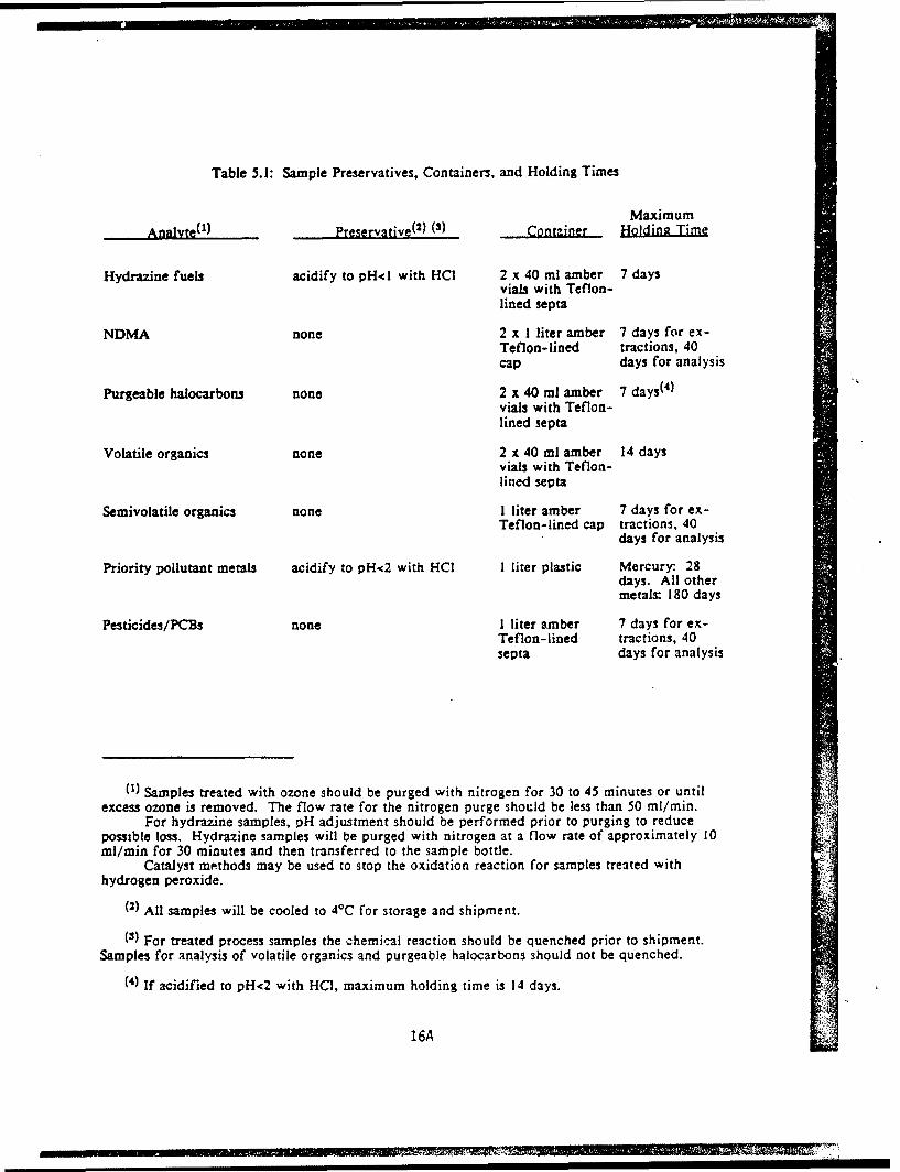
Table 5.1: Sample Preservatives, Containers, and Holding Times
MaximumAnalyte(l) Preservative(2) (3) Contziner Holding Time
Hydrazine fuels acidify to pH<l with HCl 2 x 40 ml amber 7 daysvials with Teflon-lined septa
NDMA none 2 x I liter amber 7 days for ex-Teflon-lined tractions, 40cap days for analysis
Purgeable halocarbons none 2 x 40 ml amber 7 days(4)vials with Teflon-lined septa
Volatile organics none 2 x 40 ml amber 14 daysvials with Teflon-lined septa
Semivolatile organics none I liter amber 7 days for ex-Teflon-lined cap tractions, 40
days for analysis
Priority pollutant metals acidify to pH<2 with HCl I liter plastic Mercury: 28days. All othermetals: 180 days
Pesticides/PCBs none I liter amber 7 days for ex-Teflon-lined tractions, 40septa days for analysis
(1) Samples treated with ozone should be purged with nitrogen for 30 to 45 minutes or untilexcess ozone is removed. The flow rate for the nitrogen purge should be less than 50 ml/min.
For hydrazine samples, pH adjustment should be performed prior to purging to reducepossible loss. Hydrazine samples will be purged with nitrogen at a flow rate of approximately 10ml/min for 30 minutes and then transferred to the sample bottle.
Catalyst methods may be used to stop the oxidation reaction for samples treated withhydrogen peroxide.
(2) All samples will be cooled to 40C for storage and shipment.
(3) For treated process samples the chemical reaction should be quenched prior to shipment.Samples for analysis of volatile organics and purgeable halocarbons should not be quenched.
(4) If acidified to pH<2 with HCI, maximum holding time is 14 days.
16A
NEW

II!I
I Manhole
•Manual Pump
IInc11nc PVC1
I .- -D uble
200,000 Gal. II Ball ValveApproximately E 1
3 0I //' f
I03 "Hypalon Liner
ContainmentSystemI
UI
Prepared for: Figure 5.1
U.S. Army Program Manager's Office EQUIPMENT FOR COLLECTIONFor Rocky Mountain Arsenal OF HYDRAZINE WASTEWATER
Commerce City, Colorado 1
16B 2nnni. ivm in

1I31 analytical samples will parallel that of the intended process. The wastewater collection system is
designed to allow a minimal head of approximately 3 feet to be overcome before a siphon will
3 start and induce a constant flow from US-4.
Prior to collection of wastewater, the drums, PVC tubing, pump, valves, and fittings will be
3 steam cleaned, washed with Alconox, and triple-rinsed with distilled water. Upon completion of
collection of wastewater, the pump, valves, and fittings will be decontaminated with citric acid
I solution followed by triple rinsing with distilled water. The PVC tubing will be cut into 4-foot
lengths and placed in a waste drum for storage.
Decontamination for personnel protective equipment (PPE) is discussed in the Safety Plan.
The truck containing the drums of wastewater will be driven to the RMA decontamination pad in
Section 36 of RMA. The truck and the drums will be steam cleaned, rinsed with citric acid
5 solution, and steam cleaned again. All decontamination water will be collected and drummed for
disposal at a later date.
I 5.2 ANALYTICAL SAMPLE COLLECTION
SDuring the bench/pilot-scale program and start-up zesting, wastewater samples and
treatment system off-gas samples will be collected and submitted for laboratory analysis.
Procedures for collecting these samples are descibed in the following sections.
5.2.1 Wastewater
Untreated and treated wastewater samples will be collected in the appropriate containers for
3 laboratory analyses. All samples will be cooled to 4*C and shipped via overnight carrier to HLA's
contract laboratory. The appropriate preservative and sample preparation techniques will be
3 employed prior to shipment.
Treated wastewater samples will be quenched at the time of sample collection to abate the
3 chemical destruction process. Quenching may consist of either physical purging, chemical
retarding, or enzyme treatment of the reaction and will be performed for both process stream and
3 effluent samples. Table 5.1 lists sample preservation techniques and container' for each analysis.
2000s,120.10o - RA-SDPo060o08289 17
I

II3 The following are brief summaries of the sampling procedures for collection of wastewater
samples. Wastewater samples may be obtained under several circumstances; therefore, multiple
3 procedures are included. The appropriate method will be selected at the time of sampling. The
method of sampling will be noted in the field logbook and chain-of-custody record. Details of
3 each method are included in Appendix A.
3 Peristaltic Pumo Method for Samoling Large Water Bodies
This collection system consists of a peristaltic pump capable of achieving a pump rate of I
3 to 3 liters per minute (Ipm) and an assortment of Teflon tubing for extending the suction intake.
Samples are collected through essentially chemically nonreactive material.
Extended Bottle Samoler
I The extended bottle sampler is used for collecting discrete samples from depth. The
extended bottle sampler will consist of a 1.8-m-long aluminum tube. A stainless steel clamp is
3 attached to the end of the tube and can be adjusted to hold a sample jar of desired size. The
sample jar cap can be remotely removed and replaced while the bottle is submerged by turning a
3 1.8-m-handle grip rod that attaches to the cap with a screw clamp or a suction cup.
3 Divoer or Transfer Device Samnler
A dipper or other container constructed of material not affected by hydrazine wastewater
3 can be used to transfer liquid hydrazine wastewaters from their source to a sample bottle. This
will prevent unnecessary contamination of the outer surface of the sample bottle that would
I otherwise result from direct immersion in the liquid. Use of this device will also prevent the
technician from physically contacting the waste stream. Depending on the sampling application,
3 the transfer vessel can be either disposed or reused. If reused, the vessel should be thoroughly
decontaminated prior to sampling a different source.
I20003,120.10 - MA-sDPIoWSM9 18

Ii
I
Tao or Valve Samplinu
The following procedures are to be used in sampling wastewater from taps located
3 anywhere in a wastewater treatment system:
- Approximately 100 ml of wastewater should be allowed to run from the tap beforeI sampling
- Collect wastewater not required for analyses and return to the system
3 - Triple rinse sample vial with sample wastewater
- Each sample container must be completely filled with the wastewater sample
- Cunductivity, pH, and temperature measurements, if required, will be performed on the
wastewater samples collected for inorganics analysis
- As each vial is filled, enter the applicable information on the label and pack the vial intothe shipping container. The contents of the shipping container must be kept at therequired temperature at all times.
I Note that the rinsing requirement specifically precludes adding preservative to bottles
before they are shipped to the sampling site. The sampling team will have available the correct
preservatives and will be trained in handling and dispensing the preservatives.
I 5.2.2 0ff-Gn
Off-gas samples will be collected using trapping techniques such as solid sorbents and/or
I impinger solutions. Depending on the configuration of the treatment system, the off-gas samples
may be collected from the top of the reactor vessel or from the poirt at which treated off-gas is
vented to the atmosphere. Other air samples will be collected for health and safety monitoring of
personnel and the area. This is discussed in more detail in the Safety Plan. Figure 5.2 shows a
schematic of a gas collection iystem in which impingers are used for the collection of off-gas
1 samples from chemical oxidation/UV treatment equipment.
5.3 SAMPLE CUSTODY
STo maintain and document sample possession, chain-of-custody procedures are required.
These procedures are necessary to ensure the integrity of samples from collection to data
S20003,120.10 - nIA-SDPo19

D T.
I
II
OZONEI DESTRUCT
CATALYST
EFFLUENT
IDRAIN EIVALVE
I ~DRY ICE/
ACETONEII
WATER ICE BATHII 1st IMPINGER 2nd IMPINGER
(100 ml WATER) (BEADS 3/4 VOLUME)
I GASFLOW
III
Prepared for: Figure 5.2U.S. Army Program Manager's Office SCHEMATIC OF GAS COLLECTIONFor Rocky Mountain Arsenal SYSTEM
Commerce City, Colorado

II
I
reporting. Chain-of-custody records provide the ability to trace possession and handling of
samples from the time of collection through analysis and data reporting. Details of chain-of-
custody procedures are provided in the QAPP.
A sample is considered under custody if:
- It is in your possession; or
- It is in a designated secure area.
Personnel collecting samples are responsible for the care and integrity of samples until
samples are properly transferred or dispatched. Therefore, the number of people handling a
sample should be kept to a minimum.
A Chain-of-Custody Form (Appendix B) is completed by the sampler. For wastewater
samples, chain-of-custody forms will be developed for each matrix sample. The sampler will sign
the form where indicated and record the following for each sample collected: site type, site
identification, sample date, time, depth, and sampling technique. Each chain-of-custody form
will be completed to the extent possible prior to sampling. The sampler will indicate each sample
analysis required on the chain-of-custody form and will check the sample tag (Figure B.1 in
Appendix B) and chain-of-custody record for accuracy and completeness. The Task QA/QC
Coordinator or a designated field representative will determine whether improper custody
procedures merit resampling. Only when the chain-of-custody form has been verified may the
sampler relinquish custody of the samples.
5.3.1 Chain-of-Custody Form
Chain-of-custody forms will be initiated at the time of sample collection. For each sample,
the custody form will list the fractions for analysis (for those sent to the analytical laboratory),
the date, time and location of collection, and personnel collecting the wastewater. The custody
form will remain with each sample set and will be signed and dated by both the person relin-
quishing custody and the person assuming custody each time the samples change hands. Samples
30003,120.10 - IRA-SDPoS'ON29 20

/ -
II,
I5 will be shipped to the laboratory, and custody will be documented by the airbill. The custody
form will be sealed in a plastic bag and taped to the inside of the shipping cooler lid.
3 If appropriate, the chain-of-custody forms will also be used for samples returned to the
HBSF from the laboratory or from bench/pilot-scale vendors.
1 5.4 PRESERVATION AND SHIPMENT
3 1 Wastewater shipped to HLA's contract laboratory will be maintained at 4OC or below from
the time of collection through shipment to the analytical laboratory using either ice or "blue ice"
I inside insulated sample coolers. Samples will be stored such that they will not freeze. For the
laboratory samples, the fractions for metals and certain inorganic analyses will be preserved with
Ultrex-Grade HCL, sulfuric acid, or sodium hydroxide in accordance with EPA accepted
procedures, except as specified in Table 5.1. Laboratory sample containers will be wrapped in
3 bubble-wrap, packed in ice, and shipped via overnight courier to the analytical laboratory.
IIIIIIIII 3000,121:-o - IRA-SDP
o609U289 21
II1 6.0 QUALITY CONTROL SAMPLES
The use of field Quality Control (QC) samples, duplicates, field blanks, and trip blanks is
analogous to the use of laboratory method blanks. The goal of field QC sampling is to ensure
that the sampling protocol is being properly executed and that situations leading to error are
recognized before they seriously impact the data. Field QC samples provide independent checks
on shipping, handling, and storage as well as the performance of the analytical laboratory.
6.1 SAMPLE DUPLICATES
Sample duplicates will comprise approximately 10 percent of the total investigative samples
analyzed. It is anticipated that process stream and off-gas duplicate samples will be produced at
the rate of approximately one sample per day. In these cases, the duplicate sample will have to
be determined in a random manner. Duplicate sample analysis is required for all parameters of
interest.
6.2 BLANK
F Trip blanks will be generated by the laboratory, shipped to the collection point of the
samples, and returned unopened to the analyzing laboratory. Trip blanks provide an indication of
I potential cross-contamination during sample shipment. Trip blanks are applicable to volatile
organic compounds and the hydrazine fuels. Trip blanks are to be generated at a frequency of I
per 20 investigative samples.
f 6.3 FIL LAN•
Field blanks are generally prepared at the sampling location with distilled water that has
been contacted with decontaminated sampling equipment. Field blanks are applicable to all
analytes and will be generated at a frequency of I per 20 investigative samples.
00o3,120.10 - mA-SDP,0612028922

rI1 7.0 LIST OF ACRONYMS AND ABBREVIATIONS
ANSI - American National Standards Institute
ARARs - Applicable or Relevant and Appropriat.' Requirements
Army - U.1. Department of the Army
ASTM - American Society for Testing and Materials
CAR - Contaminant Assessment Report
CDH - Colorado Department of Health
j CFR - Code of Federal Regulations
CFSR - Contract Funds Status Report (Deliverable A018)
COC - Chain of custody
COR - Contracting Officer's Representative
CPR - Cardiopulmonary Resuscitation
CRL - Certified Reporting Limit
I CRZ - Contamination reduction zone
DHHS - U.S. Department of Health and Human Services
DHSO - Designated Health and Safety Officer
DOI - U.S. Department of the Interior
DOJ - U.S. Department of Justice
DOT - U.S. Department of Transportation
DR - Data requirements (denoted AOOI through A021)
ECD - Electron capture detector
EPA - U.S. Environmental Protection Agency
f/cc - Fibers per cubic centimeter of air
FFA - Federal Facility Agreement
I GC/FID - Gas chromatography/flame ionization detector
GC/MS - Gas chromatography/mass spectrometry
2003,120.10 - MA-SDP0421082389 23
r
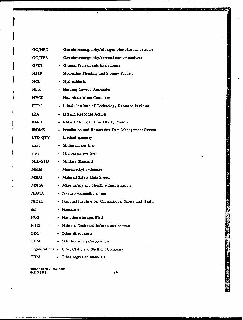
GC/NPD - Gas chromatography/nitrogen phosphorous detector
GC/TEA - Gas chromatography/thermal energy analyzer
GFCI - Ground fault circuit interrupters
HBSF - Hydrazine Blending and Storage Facility
HCL - Hydrochloric
HLA - Harding Lawson Associates
HWCL - Hazardous Waste Container
IMTRI - Illinois Institute of Technology Research Institute
IRA - Interim Response Action
IRA H - RMA IRA Task H for HBSF, Phase I
IRDMS - Installation and Restoration Data Management System
LTD QTY - Limited quantity
mg/I - Milligram per liter
us/I - Microgram per liter
MIL-STD - Military Standard
MMH - Monomethyl hydrazine
MSDS - Material Safety Data Sheets
MSHA - Mine Safety and Health Administration
NDMA - N-nitro vodimethylamine
NIOSH - National Institute for Occupational Safety and Health
nm - Nanometer
NOS - Not otherwise specified
NTIS - National Technical Information Service
ODC - Other direct costs
OHM - O.H. Materials Corporation
Organizations - EPA, CDH, and Shell Oil Company
ORM - Other regulated materials
20003,120.10 - IRA-SDP041082889 24

IOSHA - U.S. Occupational Safety and Health Administration
PCB - Polychlorinated biphenyl
PEL - Permissible exposure level
PHA - Preliminary hazard analysis
SPID - Photoionization detector
PKGS - Packages
PMRMA - Program Manager for Rocky Mountain Arsenal
PO - Purchase order
ppb - Parts per billion
PPE - Personal protective equipment
POp - Parts per million
ppt - Parts per trillion
PSN - Proper shipping name
r PVC - Polyvinyl chloride
QA - Quality assurance
QAPF - Quality Assurance Program Plan
QC - Quality control
RI - Remedial Investigation
RMA - Rocky Mountain Arsenal
"RUP - Resource Utilization Plan
SARA - Superfund Amendments and Reauthorization Act of 1986
SCBA - Self-contained breathing apparatus
SHA - System hazard analysis
Shell - Shell Oil Company
SOP - Standard Operating Procedure
SSHAR - Safety System Hazard Analysis Report
SSO - Site Safety Officer
20003,120.10 - RA-SDPo4210828 25
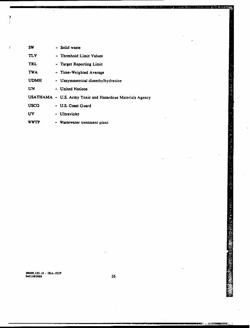
SW - Solid waste
TLV - Threshold Limit Values
TRL - Target Reporting Limit
TWA - Time-Weighted Average
UDMH - Unsymmetrical dimethylhydrazine
UN - United Nations
USATHAMA - U.S. Army Toxic and Hazardous Materials Agency
USCG - US. Coast Guard
UV - Ultraviolet
WWTP - Wastewater treatment plant
2000S,120.10 - MA-SDP04210828f 26

II1 8.0 REFERENCES
EBASCO Services, Inc., and others, June 1988, Final Report Hydrazine Blending and StorageFacility, Wastewater Treatment and Decommissioning Assessment, Version 3.1, Contract No.DAAKI 1-84-D-0017.
Harding Lawson Associates, April 27, 1989, Draft Procedure for Collection of HydrazineWastewater for Bench/Pilot-Scale Testing
Harding Lawson Associates, May 19, 1989, Draft Task Plan, Hydrazine Blending and StorageFacility IRA Implementation
Harding Lawson Associates, June 1989, Draft Quality Assurance Program Plan, HydrazineBlending and Storage Facility IRA Implementation.
PMRMA, September 1988, Final Decision Document for the Interim Response Action at theRocky Mountain Arsenal Hydrazine Blending and Storage Facility.
Task Order IRA H Phase I Hydrazine Blending and Storage Facility (HBSF), Interim ResponseAction (IRA) Mobilization, Correspondence from Ernest Henry, Contracting Officer, Procure-ment Director (Edgewood), to Arthur C. Riese, HLA-Denver, Colorado, December 22, 1988.
USATHAMA, March 1987, Installation Restoration Quality Assurance Program.
I
I
20003,20.10 - IA-MDP0612W2U9 27

Appendix A
SAMPLING PROCEDURES

UJ
II
SAMPLING PROCEDURES
COLLECTION OF WASTEWATER SAMPLES FROM TAP OR VALVE
The following procedures will be used to sample wastewater from taps in a wastewater
supply system:
1. Wastewater will be allowed to run from the tap for 2 to 3 minutes before sampling.
2. Sample vial will be triple rinsed with wastewater from the source to be sampled.
3. Measurements of conductivity, pH, and temperature, if required, will be recorded forsamples collected for inorganics analysis.
4. As each vial is filled, applicable information will be entered on the label. The vial willthen be packed into the shipping container. The contents of the shipping container will3 be maintained at the required temperature at all times.
Note that the rinsing requirement specifically precludes addition of preservative to bottles before
m they are shipped to the sampling site. Correct preservatives must be available to the sampling
team, who will be trained in handling %ind dispensing preservatives. If drinking water quality is
to be assessed, samples must be collected from taps downstream of any water treatment processes.
3 COLLECTION OF SAMPLES FROM LARGE WATER BODIES USING A PERISTALTICPUMP
This collection system consists of a peristaltic pump capable of achieving a pumping rate of
I to 3 liters per minute and various sizes of Teflon tubing for extending the suction intake. A
battery-operated pump is preferable.
The system is illustrated in Figures A.1 and A.2. Samples are collected through material
3 that is essentially chemically nonreactive. The system is practical for a wide range of applica-
tions, including sampling from streams, ponds, and containers. The equipment can be modified
to extend the lateral reach of the sampler and to allow sampling from depth. The system can
function both as a well purge and a sample collection system. The primary disadvantage of this
3 method is the limited lift capacity of the pump (approximately 8 meters).
1 20003,120.10 - IRA-SDPo812082989 A-1
I

//
III
II
, , .M o . S T gRO, , ' ',
I
U oR6 SORPLS MOTPLE 60I
III
1_1Prepared tar: Figure A.1* U.S. Army Program Manager's Office PERISTALTIC PUMP FOR LIQUID- for Rocky Mountain Arsenal SAMPLING (MODIFIED)Commerce C~ty, Colforado
A-1 a

II
IIII
I ~PE[ItSTAILTIC
IMEWMCAt. CNaw SILICONE
It3. . I /
Of TI PLO N DIJSCHbG
TO SAMtlE COINTAuqL
III
'II
Prepared for: Figure A.23 U.S. Army Program Manager's Office PERISTALTIC PUMP FOR LIQUIDfor Rocky Mountain Arsenal SAMPLING
I Commerce City, Colorado

UI
Procedures for Use
1. Install clean, medical-grade silicone tubing in the pump head according to the manu-facturer's instructions. Allow sufficient tubing on the discharge side to facilitateconvenient dispensing of liquid into sample bottles and only enough on the suction endfor attachment to the intake line. This practice will minimize sample contact with thesilicone tubing.
1 2. Select the length of intake tubing necessary to reach the required sample depth andattach to intake side of pump tubing. Heavy-wall Teflon, of a diameter equal to therequired pump tubing, suits most applications. (Heavier wall Teflon will allow for aslightly greater lateral reach.)
3. If possible, allow several liters of sample to pass through the system kefore samplecollection. Collect this purge volume and return it to the source after the sample hasI been collected.
4. Fill necessary sample bottles by allowing pump discharge to flow down the side of thei bottle.
5. Preserve the sample, if necessary, according to guidelines.
6. Check that a Teflon liner is in the cap. Secure the cap tightly.
7. Place the properly labeled sample bottle in an appropriate carrying container maintainedat 4OC throughout the sampling and transportation period.
8. Dismantle the sampler. Wipe the components with absorbent towels and place thecomponents in plastic bags for subsequent cleaning. Place used towels in plastic bags forsubsequent disposal.
Sources
i Devars, E.R., Simmons, B.P., Stephens, R.D., and Storm, D.L., Samplers and SamplingProcedures for Hazardous Waste Streams, EPA-600/2-80-018, January 1980.
GCA Corporation, Quality Assurance Plan, Love Canal Study - Appendix A, SamplingProcedures, EPA Contract 68-02-3168
COLLECTION OF WATER SAMPLES FROM DEPTH WITH AN EXTENDED BOTTLE
SAMPLER
The extended bottle sampler consists of a 6-foot-long aluminum tube (Figure A.3) with a
stainless steel adjustable clamp attached to the end of the tube. While the sample bottle is
submerged, the sample jar cap can be remotely removed and replaced by turning the handle grip
rod, which attaches to the cap with a screw clamp or suction cup.IS•o000s,120.10 - MA-SDP
0612082338 A-2
I

II
III
-Cmec Ciy olrd
I ..
!! I
IIiI,II
ip
II
Prepared for: Figure A.3IU.S. Army Program Manager's Office EXTENDED BOTTLE SAMPLER
for Rocky Mountain ArsenalI Commerce City, Colorado

I
The extended bottle sampler is a grab sampler designed to sample subsurface liquids to a
maximum depth of 5 feet. Because the outside of the sample bottle will be exposed to the
wastewater, the bottle must be decontaminated prior to shipment. The extended bottle sampler
must also be decontaminated prior to reuse.
Procedures for Use
1. Place an uncontaminated, capped bottle in the stainless steel clamp.
2. Attach the rod to the cap with the screw clamp or suction cup.
3. Lower the sampler to the desired depth of the wastewater.
4. Turn the handle grip rod to remove the cap.
5. Allow the bottle to fill, then replace the cap.
6. Raise the sampler, and thoroughly decontaminate it prior to the next use.
SAMPLING WASTEWATER WITH A TRANSFER VESSEL
A dipper or other sampler constructed of inert material, such as stainless steel or Teflon,
can be used to transfer liquid waste from the source to a sample bottle. This prevents unneces-
sary sample bottle contamination that would otherwise result from direct immersion in the liquid.
Use of this device also prevents the technician's physical contact with the waste stream.
Depending on the sampling application, the transfer vessel can be either disposed or reused. If
reused, the vessel should be thoroughly decontaminated prior to sampling a different source.
U=e
A transfer vessel can be utilized in most sampling situations, except those in which aeration
must be eliminated, such as volatile organic analysis or when significant material may be lost by
adhesion to the transfer container.
Procedures for Use
I. Submerge, with minimal surface disturbance, a stainless steel dipper or other suitablevessel.
2OW3,120.10 - MIA-sDP0612082819 A-3

II
2. Allow the vessel to fill slowly and continuously.
3. Retrieve, with minimal disturbance, the vessel from the surface water.
4. Remove the cap from the sample bottle, and slightly tilt the mouth of the bottle belowthe edge of the sampling vessel.
5. Slowly empty the vessel, allowing the sample stream to flow down the side of thebottle.
6. Continue delivery of the sample until the bottle is almost completely filled, leaving3 adequate volume to allow for expansion.
7. Preserve the sample, if necessary, according to guidelines.
1 8. Check that a Teflon liner is in the cap. Secure the cap tightly.
9. Place the properly labelcd sample bottle in an appropriate carrying container main-tained at 4OC throughout the sampling and transportation period.
10. Dismantle the sampler. Wipe the components with absorbent towels and place thecomponents in plastic bags for subsequent cleaning. Place used towels in plastic bagsfor subsequent disposal.
&ources
GCA Corporation, Quality Assurance Plan, Love Canal Study - Appendix A, SamplingProcedures, EPA Contract 68-02-3168.I
IIUI
I
2000,120.10 - IRA-SDP0612o82M9 A-4

IJ
III1III-I
I Appendix H
FORMSIIIII
I

>I --0oi;A -14a 1 -0
LU01*/Z -d cc >, G
- - - - - -Vd- LU -
u__ _ _ _ 0 u 0 0 gO~O9/uO w4 0 w' U ' U
I, 2 za
-- 2
* 0CL I.-
*~u -i - - - -
00 (m
--. - - .t -2 -C
UA W
-I. UJ Lca -Z z- -
0 -
ins~ _>
00 ~~os --U
1!*z ~ ~ ~ ~ R 01Uufa cF

3I
r. wo, .3S- -, -v..
_ .g
0 a- : i
~. c
30 0-0 Qn c
2.2
0. ' I ..z.
CC*00
Cc
aa- : - Co0 RNA; -- ~~

Harding LewsolAsoia
Jaw
'oep
U.S Ary Pogrm Mnagr'COffAicAeD SAMPLE LBLFor__ RokyMonaitAsea
Comm~::< City,;~ Coloado

Appendix C
RESPONSES TO COMMENTS SUBMITTED BY EPA AND SHELL OIL COMPANY

III AM
UNITED STATES ENVIRONMENTAL PROTEC11ON AGENCYREGION V1I
999 18th STREET - SUITE 500DENVER, COLORADO 80202-2405
JUL 31 IM8
Ref: 8HWM-SR
Mr. Donald L. CampbellOffice of the Program ManagerRocky Mountain ArsenalATTN: AMXRM-PMCommerce City, Colorado 80022-2180
Re: Rocky Mountain Arsenal (RMA)Draft Final Task Plan, HydrazineBlending and Storage Facility(HBSF), Interim Response Action
a MImplementation, June 1989.
Dear Hr. Campbell:
We have reviewed the above referenced document and theaccompanying Sampling Design Plan, Quality Assurance ProgramPlan, and the Safety Plan for this IRA. We have the enclosedcomments. The more important issues were discussed at the SBSFI, Subcommittee on July 21, 1989, and were resolved in thesediscussions with Army representatives. Please contactLinda Grimes at (303) 293-1262, if you have questions on thismatter.
Sincerely,
•.onnally HearsSI EPA Coordinator for RMA Cleanup
Enclosure
cc: Jeff Edson, CDHDavid Shelton, CDHVicky Peters, CAGOLt. Col. Scott P. IsaacsonChris Hahn, ShellR. D. Lundahl, ShellJohn Moscato, DOJDavid Anderson, DOJ
C-i

II
COMMENTS ON THE DRAFT FINAL TASK PLAN, THE SAMPLING DESIGN PLAN,THE QUALITY ASSURANCE PROGRAM PLAN, AND THE SAFETY PLAN FOR THE
HYDRAZINE BLENDING AND STORAGE FACILITYINTERIM RESPONSE ACTION IMPLEMENTATION
JUNE 1989
1. Passages from the Decision Documen:, on pages 33, 34 and 52,reflect EPA's understanding of the Army's agreed approach totreatment of the hydrazine blending and storage facilitywastewater. The Army agreed to attempt lowering of the detection Ilimit for NDMA and extrapolation of the treatment curve to attainthe Ambient Water Quality Criteria for NDMA of 1.4 ppt, prior torelease from the treatment system. Following discussions with IArmy staff, it is our understanding that page 7, Section 1.2.4,and page 9. Section 2.2.2, of the Draft Final Task Plan, will bemodified to reflect the approach agreed upon in the DecisionDocument.
2. As discussed at the HBSF Subcommittee and as agreed by theArmy, we wish to emphasize that we fully anticipate compliance Uwith ARARs established for this IRA, during the onpost pilottreatment studies. Further, all onpost treatability studies,with potential for releases, are subject to ARARs analysis and Icompliance.
3. Although soils and. groundwater remediation are not withinthe scope of the IPA, we recommend the development of a cartifi6d Ireporting limit for the NDMA in soils, to be conducted during theIRA work. These issues were discussed at the SBSF Subcommittee,and the Army representatives suggested inclusion of this soil Isampling as part of the data gap soils study. We request thatsoils sampling in the HBSF area following decommissioning beconsidered a data gap and be addressed by that soil samplingprogram.
4. It is our understanding that the assumption that destructionof NDMA would appropriately destroy other contaminants (includingchlorinated hydrocarbons) would be further assessed during theinitial system tests to prope.:ly select compounds to bemonitored. Based on discussions with Army representatives, the Icurrently planned pilot testing and startup testing will includethis evaluation.
5. We have concerns that potential air release of NOMA wasevaluated for workers only and not offpost areas. At ourrequest, Army representatives have agreed to conduct anevaluation of the potential for the exposure of offpost areas andthe placement of statements in the Task Plan to reflect this.
6. The plan does not monitor for BOD 5 and ciemical oxygendemand of the effluent from the treatment system. The BOD 5 andchemical oxygen demand should be compared with the influent
C-2 2

II
levels to predict the potential loading of BOD on the sewagetreatment plant. A discharge of 1,000 gallons of treatedwastewater with a high BOD concentration could have an adverseeffect on the sewage treatment plant, possibly causing aviolation of the effluent limitations in the NPDES permit.
7. Draft Final Task Plan, page 5, clarify the text that furthertreatment of the 10,000 gallons of startup wastewater may benecessary to achieve acceptable discharge levels. What is theanticipated storage time in tanks?
8. Draft Final Task Plan, page 7, last paragraph, is there aprediction of the anticipated quantity of rinse water producedand subsequently treated by this system and released to the sewersystem? The decommissioning phase should review other methods todecontaminate the storage units, since the levels of NDMA in theair within the tanks used to blend, formulate, and storehydrazine ranges from 0.20 ug/m 3 to 28 ug/m 3 (page 8, Draft FinalSafety Plan).
9. Draft Final Task Plan, pages 5 and 11, we note that weatherimpacts have been considered in the selection and design of theelectrical system. Have temperature effects on the UV/oxidationprocess performance been evaluated?
1 10. Draft Final Task Plan, pages 9 and 10, and Draft FinalSampling Design Plan, pages 5 and 6, the text states thatpretreatment may be necessary to remove sediments, metals, andother contaminants. The concentrations of other contaminantsshould be better evaluated and Table 2.1 expanded to indicatetheir levels. This assessment should include the analysesresults for pH, hardness (scale control on UV quartz tubes),total organic carbon, chloride, ammonia, nitrate, etc. Also,further testing should be done to better define the concentrationlevels; for example, Table 2.1 lists UDMH at concentrationsranging from greater than 5 to 1000 ppm. If the impact ofconcentration variation on system optimization has beenevaluated, the results should be presented.
11. Draft Final Task Plan, page 11, since the catalyst has notbeen identified at this point, its effluent discharge may not beregulated as part of the NPDES discharge to the RMA sanitarysewer. After a catalyst has been selected, notify EPA so that wecan assure proper monitoring is occurring.
12. Draft Final Task Plan, pages 12 and 13, the text states thatthe supervision of the treatment process will be limited to 16hours; will the reaction proceed unmonitoree by an operatorbeyond this point? Will there be checks/alarms to alerttemperature buildup or leakage; is there a remote alarmnotification system? It is stated that an automatic shutdown
C-33

I1
will occur in the event of a system failure; are any operatorprocedures required following automatic shutdown? 313. Draft Final Safety Plan, page 7, is ground water monitoringbeing conducted for the inground concrete tank? Is this tankcovered? 314. Draft Final Safety Plan, page 7, from what drum filling andwashing operations were residues collected and stored in the in-ground concrete tank?
15. Draft Final Safety Plan, page 7A, the figure should includethe location of the inground tank and the equipment sheds.
16. Draft Final Safety Plan, page 23, Section 6.6, what are thepredetermined concentrations against which ambient air levels Iwill be monitored?
17. Draft Final Safety Plan, refer to earlier Comment 5, 1regarding public protection, the system will be equipped with an Uaudible alarm activated when the Threshold Limit Value (TLV) of0.1 ppm is exceeded. When the plant is unattended, the 3audible/visual alarm will be activated, how will RMA personnel beaware of the alarm; is there a remote alarm notification system?Also, this section establishes a notification procedure, which isnot inclusive of public notification. Procedures and levels mustbe determined that are protective of the public and a contingency -plan developed for releases that could impact public health.
18. Draft Final Sampling Design Plan, pages 8 and 10, in regard Ito the evaluation of the off-gassing from a non-ozone system,there are contradictions. In one case, it is stated that theoff-gas stream will not be sampled; in the second instance, it is 3stated that the off-gassing from the hydrogen peroxide processwill be evaluated. Please amend the text to clarify thisapparent contradiction.
19. Draft Final Sampling Design Plan, page 13, are CRLscurrently in existsnce for other contaminants of concern in thewastewater?
20. Draft Final Quality Assurance Program Plan, page 4, pleaselist what materials, other than anhydrous hydrazine andunsymmetrical dimethylhydrazine, were loaded and unloaded here.Also, expand the text to include any history of spills of thesesubstances here. i21. Draft Final Quality Assurance Program Plan, pages 5 and 7,it is our understanding that the Draft Implementation Documentwill address the treatment of the approximately 300,000 gallons Iof hydrazine wastewater. Further, we understand that theselection of the "full-scale treatment system" and its startup
C-4 4
U

testing will occur following review and comment by the parties ofthe Implementation Document (refer to Sections 22.13 and 22.14 ofthe FFA). Please amend the text to reflect that this agreedprocedure will be followed.
1 22. Draft Final Task Plan, the following technical information,regarding the bench scale/pilot testing program, is requested:
a. What type of reactor system is going to be used for thebench scale test and what are the scale-up problemsassociated with that system?
b. Are different intensity UV lamps to be evaluated inthis phase?
I c. Are different UV wavelengths to be evaluated in thisphase?
d. What data will be generated to do the treatmentextrapolation for NDMA required hy the Final DecisionDocument?
1 e. Are different treatment pHs to be evaluated?
f. Will the effluent from the bench/pilot testing beevaluated for the formation of degradation by-productswhich have been observed in other testing?
g. Will pH measurements be taken on the influent andeffluent samples from the bench/pilot testing?
h. Will the sampling procedure minimize vapor space in thesample containers to ensure that VOCs are not purgedfrom the sample during transport?
IIIIIB C-5 5
I

I
testing will occur following review and comment by the parties ofthe Implementation Document (refer to Sections 22.13 and 22.14 ofthe FFA). Please amend the text to reflect that this agreed Iprocedure will be followed.
22. Draft Final Task Plan, the following technical information, 3regarding the bench scale/pilot testing program, is requested:
a. What type of reactor system is going to be used for thebench scale test and what are the scale-up problems Iassociated with that system?
b. Are different intensity UV lamps to be evaluated in Ithis phase?
C. Are different UV wavelengths to be evaluated in this 5phase?
d. What data will be generated to do the treatmentextrapolation for NDMA required by the Final Decision iDocument?
e. Are different treatment p~s to be evaluated? 5f. Will the effluent from the bench/pilot testing be
evaluated for the formation of degradation by-productswhich have been observed in other testing?
g. Will pH measurements be taken on the influent andeffluent samples from the bench/pilot testing?
h. Will the samplig procedure minimize vapor space in thesample containers to ensure that VOCs are not purged Ifrom the sample during transport?
FCD:July 31 , 1989:asap\hbsfrv.new Ibcc: Connally Mears, 8HWM-SR
Linda Grimes, 8HWM-SRKay Modi, 8HWM-SRBill Clemmens, 8RCMike Gaydosh, 8RCBruce Ray, 8RCMike Smith, CDM
I!
-65 1U

I
RESPONSES TO COMMENTS SUBMITTED BY THEU.S. ENVIRONMENTAL PROTECTION AGENCY, REGION VIII, ON THE
DRAFT FINAL TASK PLAN, SAMPLING DESIGN PLAN,
QUALITY ASSURANCE PROGRAM PLAN, AND SAFETY PLAN FOR THEHYDRAZINE BLENDING AND STORAGE FACILITY
INTERIM RESPONSE ACTION
I Comment No. I
Passages from the Decision Document, on pages 33, 34, and 52. reflect EPA's understanding of theArmy's agreed approach to treatment of the hydrazine blending and storage facility wastewater.The Army agreed to attempt lowering of the detection limit for NDMA and extrapolation of thetreatment curve to attain the Ambient Water Quality Criteria for NDMA of 1.4 ppt, prior to releasefrom the treatment system. Following discussions with Army staff, it is our understanding that
I page 7, Section 1.2.4. and page 9. Section 2.2.2, of the Draft Final Task Plan, will be modified toreflect the approach agreed upon in the Decision Document.
S~Response
EPA's understanding is correct, and the text of the Task Plan has been modified to reflect theapproach agreed upon in the Decision Document.IComment No. 2
As discussed at the HBSF Subcommittee and as agreed by the Army, we wish to emphasize that wefully anticipate compliance with ARARs established for this IRA during the onpost pilot treatmentstudies. Further, a!l onpost treatability studies, with pofential for releases, are subject to ARARsanalysis and compliance.
SResp~onse
Comment noted.
Commnent No. 3
I Although soils and groundwater remediation are not within the scope of the IRA, we recommend thedevelopment of a certified reporting limit for NDMA in soils to be conducted du;ing the IRA work.The.-e issues were discussed at the HBSF Subcommittee, and the Army representatives suggestedinclusion of this soil sampling as part of the data gap soils study. We request that soils samplingin the HBSF area following decommissioning be considered a data gap and be addressed by thatsoil sampling program.
I Restoonse
EPA's understanding that soils and ground-water remediation are not within the scope of the IRAis correct; therefore, a CRL for NDMA in soils will not be developed during the IRA work. Soilsampling for NDMA in the H3SF area was conducted in 1988 and 1989. The data and resultswere presented in the "Final Phase I Contamination Assessment Report, Site 1-7, HydrazineBlending and Storage Facility, Version 3.2" (September 1988) and in the "Final Phase 11 DataAddendum, Site 1-7, Hydrazine Blending and Storage Facility, Version 3.1" (February 1989). Itshould be noted that no NDMA was detected at or above detection limits in either stwdy and that
20003,120.10 - IhA-SD7os0oos2038 C-7

the detection limit was lowered by a factor of 10 between Phase I and Phase II. The Armybelieves that sufficient data already exist on NDMA in soils in the HBSF area and therefore does Inot consider HBSF soils sampling for NDMA to be a data gap.
Commen~t No. 4
It is our understanding that the assumption that destruction of NDMA would appropriately destroyother contaminants (including chlorinated hydrocarbons) would be further assessed during theinitial system tests to properly select compounds to be monitored. Based on discussions with Army Urepresentatives, the currently planned pilot testing and startup testing will include this evaluation.
ResponseI
EPA's understanding is correct.
We have concerns that potential air release of NDMA was evaluated for workers only and notoffpost areas. At our request. Army representatives have agreed to conduct =n evaluation of thepotential for the exposure of offpost areas and the placement of statements in the Task Plan toreflect this. IResnonse
EPA's understanding is correct, and the following text will be added as a seventh bullet inSection 1.1.3.2 of the Task Plan: "The EPA Industrial Source Complex Dispersion Model (EPA, I1987) will be used to determine whether exposure to Off-Post areas will occur if airborne NDMAis released from the hydrazine wastewater treatment system." *
Comment No. 6
The plan does not monitor for BOD and chemical oxygen demand of the effluent from the 1treatment system. The BOD and chemical oxygen demand should be compared with the influentlevels to predict the potential loading of BOD" on the sewage treatment plant. A discharge of 1,000gallons of treated wastewater with a high BOD concentration could have an adverse effect on thesewage treatment plant, possibly causing a violation of the effluent limitations in the NPDES Ipermit.
Rest~onse
Based on the existing analytical results for hydrazine wastewater at the HBSF and anticipatedconcentrations of NDMA, hydrazine fuels, and other organics in treated effluent from thehydrazine wastewater treatment system, the BODs and COD concentrations in the treated effluent Iare expected to be insignificant.
To verify BODs and COD concentrations in the treated effluent from the hydrazine wastewatertreatment system, BOD5 and COD analyses will be included in the start-up testing program.
20003,120.10 - IRA-SDPo02g99oag C-8a
1i

SComment No. 7
Draft Final Task Plan, page 5, clarify the text that further treatment of the 10,000 gallons ofstartup wastewater may be necessary to achieve acceptable discharge levels. What is the anticipatedstorage time in tanks?
Treated effluent from the chemical oxidation/UV treatment system will be stored in effluentstorage tanks prior to discharge. Samples of the effluent will be shipped for analyses to theanalytical laboratory certified for analysis of NDMA and hydrazine fuels. Based on the results ofthe analyses relative to CRLs for these compounds, the treated effluent will be either dischargedto the RMA sanitary sewer or directed to the hydrazine wastewater treatment system for furthertreatment.
The anticipated storage time for the treated effluent is approximately 30 days, the length of timerequired to receive preliminary corrected results from the analytical laboratory.
Draft Final Task Plan. page 7, last paragraph, is there a prediction of the anticipated quantity ofrinse water produced and subsequently treated by this system and released to the sewer system?The decommissioning phase should review other methods to decontaminate the storage units, sincethe levels of NDMA in the air within 'he tanks used to blend, formulate, and store hydrazine rangesfrom 0.20 jig/rmn to 28 ~g/mn3 (page 8, Draft Final Safety Plan).
Resnonse
An estimate of the anticipated quantity of rinse water generated during decommissioning, subse-quently treated by the hydrazine wastewater treatment system, and discharged to the RMAsanitary sewer is not available at this time. An estimate will be prepared and will be included inthe Draft Implementation Document for deccmmissioning of the HBSF.
j All decontamination methods were assessed in the assessment phase of the IRA and werepresented in the Final Assessment Document. The Final Decision Document for the IRA specifiesthe decommissioning process.
Comment No. 9Draft Final Task Plan, pages 5 and 11, we note that weather impacts have been considered in theselection and design of the electrical system. Have temperature effects on the UV/oxidationprocess performance been evaluated?
IResoonse
Temperature effects on the performance of the UV/oxidation process treating hydrazine waste-water from the HBSF have not been evaluated to date. These effects will be evaluated during thestart-up testing phase of this task. The temperature of the hydrazine wastewater will increaseduring the UV/oxidation process. A chiller will be included with the hydrazine wastewatertreatment system to control temperature increase.
20003,120.10 - MA-SDPj82908og C-9
I

IComment No. 10
Draft Final Task Plan, pages 9 and 10, and Draft Final Sampl,.ig Design Plwr, pages 5 and 6, thetext states that pretreatment may be necessary to remove sediments, metals. amd other contaminants.The concentrations of other contaminants should be better evaluated and Table 2.1 expanded toindicate their levels. This assessment should include the analyses results for pH. hardness (scalecontrol on UI, quartz tubes), total organic carbon, chloride, ammonia, nitrate, ec. Also, furthertesting should be done to better define the concentration levels: for example. Table 2.1 lists UDMHat concentrations ranging from greater than 5 to 1000 ppm. If the impact of concentration Ivariation on system optimization has been evaluated, the results should be presented.
The impact of concentration variation on optimization of the hydrazine wastewater treatmentsystem has not been evaluated to date. Additional sampling and analysis of the contents of thethree tanks that contain hydrazine wastewater at the HBSF will be conducted to better assessconcentrations of the parameters listed in Table 2.1 of the Draft Final Task Plan. Analyses forparameters that may affect performance of the hydrazine wastewater treatment system (e.g., pH,hardness) will be performed. The sampling locations, parameters, and methods of analysis forthis additional samping and analysis will be presented as an addendum to the Sampling Design iPlan prior to the work being performed.
Comment No. I1 I
Draft Final Task Plan. page 11. since the catalyst has not been identified at this point, its effluentdischarge may not be regulated as part of the NPDES discharge to the RMA sanitary sewer. Aftera catalyst has been selected, notify EPA so that we can assure proper monitoring is occurring.
Resoonse []
Comment noted. The Army will coordinate with EPA to ensure that necessary revisions are madeto the NPDES permit application where appropriate. EPA will be notified when a catalyst hasbeen selected. I
Comment 12
Draft Final Task Plan, pages 12 and 13, the text states that the supervision of the treatment Iprocess will be limited to 16 hours: will the reaction proceed unmonitored by an operator beyondthis point? Will there bc checks/alarms to alert temperature buildup or leakage: is there a remotealarm notification system? It is stated that an automatic shutdown will occur in the event of a Isystem failure; are any operator procedures required following automatic shutdown?
Response1
No remote alarm notification system is planned, as an operator will be present at all times duringsystem operation. Instrumentation will be included with the system to monitor process parameterssuch as temperature, pH, pressure, and flow rate. Real-time monitoring will be included forairborne hydrazine fuels. Non-real-time monitoring will be performed for airborne NDMA.Tanks within the system will include high-level alarms. I20003,120.10 - IRA-SDP C082M3089 C-10I

I/
IOperator procedures following automatic shutdown will be required. These procedures will beoutlined in the Draft Operation and Program Manual for the hydrazine wastewater treatmentsystem. This manual will be prepared prior to 'tart-up operation of the system.
I Comment No. 13
Draft Final Safety Plan, page 7, is ground water monitoring being conducted for the ingroundconcrete tank? Is this tank covered?
Resmonse
I Ground-water monitoring for the in-ground concrete tank/sump will not be conducted as a partof Phase I of this IRA. The tank is not covered.
I Comment No. 14
Draft Final Safety Plan, page 7, from what drum filling and wasning operations were residuescollected and stored in the inground concrete tank?
Resm~nse
I The statement on page 7 of the Draft Final Safety Plan regarding drum filling and washingoperations refers to page 1-13 of the Final Assessment Document, which states that dirty drumsand drums to be reused were cleaned before filling, and residues were poured into the in-groundtank/sump. This statement reflects all information in the available documents.
Comment No. 15
Draft Final Safety Plan, page 7A, the figure should include the lo,:ation of the inground tank andthe equipment sheds.
Response
Figure 3.1 of the Final Safety Plan has been modified to show the locations of the in-ground tankand equipment sheds.
Comment No. 16
Draft Final Safety Plan, page 23, Section 6.6, what are the predetermined concertrations againstwhich ambient air levels will be monitored?
Response
The U.S. Occupational Safety and Health Administration (OSHA) Permissible Exposure Limits(PELs) and American Conference of Government Industrial Hygienists (ACGIH) Threshold LimitValues (TLVs) for hydrazine, MMH, and UDMH are as follows:
20003,120.10 - IMA-SDP0829083089 C-11

I
PEiLand TL!
Hydrazine 0.1 ppm
MMIH 0.2 ppm
UDMH 0.5 ppm
Comment No. 17
Draft Final Safety Plan, refer to earlier Comment 5. regarding public protection, the system will Ube equipped with an audible alarm activated when the Threshold Limit Value (TLV) of 0.1 ppm is nexceeded. When the plant is unattended, the audible/visual alarm will be activated, how will RMApersonnel be aware of the alarm; is there a remote alarm notification system? Also, this sectionestablishes a notification procedure, which is not inclusive of public notification. Procedures andlevels must be determined that are protective of the public and a contipgency plan developed forreleases that cculd impact public health.
Resoonse nNo remote alarm notification system is planned, as an operator will be present at all times duringsystem operation. PMRMA has an established notification procedure that will be followed.
Comment No. 18
Draft Final Sampling Design Plan, pages 8 and 10, in regard to the evaluation of the off-gassing Ifrom a nonozone system, there are contradictions. In one case, it is stated that the off-gas streamwill not be sampled; in the second instance, it is stated that the off-gassing from the hydrogenperoxide process will be evaluated. Please amend the text to clarify this apparent contradiction. 1Resoone
Section 3.1.5 of the Sampling Design Plan refers to off-gas testing during bench/pilot-scale U==testing; no off-gas testing is planned for the non-ozone unit during bench/pilot-scale testing.Section 3.2.4 refers to off-gas testing during start-up testing; the selected treatment unit will betested for off-gassing during start-up testing. Whether an ozone or a non-ozone chemicaloxidation/UV system is selected, provisions will be incorporated in the design of the hydrazine nwastewater treatment system to collect gases that may be generated in the unit processes and tanksemployed in the treatment system. The design will include a series of seal water tanks, throughwhich off-gases must pass. At the end of a batch run during start-up operation, the seal water Iwill be analyzed to determine whether off-gassing occurred during the run.
Comment No. 19
Draft Final Sampling Design Plan, page 13, are CRLs currently in existence for other con-taminants of concern in the wastewater?
Response
Yes. CRLs exist for all contaminants listed on page 10 of the Draft Final Task Plan except (1)sodium hypochlorite and chlorine residuals, which do not have certifiable methods and (2)
20003,120.10 - IRA-SDP CI0829asos C- 12 I

dimethylcyanamide, N-N-dimethylformamide, I-ethyl IH 1,2,4-Triazole, and Silvex, which atthis point are considered tentatively identified compounds (TICs).
Comment No. 20
Draft Final Quality Assurance Program Plan, page 4, please list what materials, other thananhydrous hydrazine and unsymmetrical dimethylhydrazine. were loaded and unloaded here. Also,expand the text to include any history o. spills of these substances here.
Resiponse
The Final Assessment Document contains the information pertaining to history of loading andunloading as well as spills.
Comment No. 21
Draft Final Quality Assurance Program Plan, pages 5 and 7, it is our understanding that the DraftImplementation Document will address the treatment of the approximately 300,000 gallons ofhydrazine wastewater. Further, we understand that the selection of the "full-scale treatmentsystem' and its startup testing will occur following review and comment by the parties of theImplementation Document (refer to Sections 22.13 and 22.14 of the FFA). Please amend the textto reflect that this agreed procedure will be followed.
Response
EPA's understanding that the Draft Implementation Document will address treatment of approxi-mately 300,000 gallons of hydrazine wastewater is correct. Selection of the full-scale treatmentsystem and its start-up testing, however, will occur during the design phase of the project andprior to issuing the Draft Implementation Document. As discussed at the RMA Subcommitte3meeting on July 21, 1989, the full-scale treatment system has been selected, and, based on theresults of the start-up testing, any necessary modifications v -ll be implemented and recommenda-tions for full-scale treatment will be made. Modifications and recommendations will be presentedin the Draft Final Implementation Document for review and comment by the parties, perSections 22.i 3 and 22.14 of the Federal Facility Agreement.
Comment No. 22
Draft Final Task Plan, the following technical information for the bench scale/pilot testingprogram, is requested:
A. What type of reactor system is going to be used for the bench scale test and what are thescale-up problems associated with that system:
Response
Three chemical oxidation/UV reactor system configurations will be evaluated during thebench/pilot-scale testing program:
- Hydrogen peroxide/ozone (or ozone alone) in combination with multiple low-intensityUV rays (254 nm wavelength): bench-scale
20003,120.10 - IRA-SDP0820808 C-13

II
- Hydrogen peroxide in combination with multiple high-intensity UV lamps (254 nmwavelength): bench-scale
- Hydrogen peroxide/ozone (or ozone alone) in combination with a single medium-intensity UV lamp (broad wavelength. 200 to 350 nm): pilot-scale
Scale-up problems, if any, are unknown at this time and cannot be predicted.
B. Are different intensity UV lamps to be evaluated in this phase?
Resonse
Yes, see response to Comment 22A.
C. Are different UW wavelengths to be evaluated in this phase? URestonse I
Yes, see response to Comment 22A.
D. What data will be generated to do the treatment extrapolation for NDMA required by the IFinal Decision Document?
Resiponse
Because of the volume of sample required to characterize the treated effluent generated from a
particular bench-scale or pilot-scale run, no sampling during the intermediate stages of a run isanticipated. Thus, generation of concentration versus time curves or kinetic modeling fortreatment of NDMA is not an objective of the bench/pilot-scale testing program. Generation of
data for extrapolation of treatment for NDMA is planned for the full-scale start-up testing phaseof the task. 3
E. Are different treatment pHs to be evaluated?
Response
Yes. Each vendor will provide recommendations regarding optimum pH for treatment of
hydrazine wastewater from the HBSF.
F. Will the effluent from the bench/pilot testing be evaluated for the formation of degrada-tion by-products which have been observed in other testing?
Response
Yes. Refer to pages 5, 7A, 8, and 14 of the Draft Final Sampling Design Plan for the parametersto be analyzed in the final treated effluent samples. I20003,120.10 - tRA-SDP Co8290o308 C- 4
I
S .. .. II -

G. Will pH measurements be taken on the influent and effluent samples from the bench/pilottesting?
Response
Yes.
H. Will the sampling procedure minimize vapor space in the sample containers to ensure that
VOCs are not purged from the sample during transport?
Rewon-g
Yes.
20003,120.10 - JRA-SDP032900808 C-15

Shell 011 Company 0one U41 Pfau1PI 0. BA=
Haumn. 7*exu Trt210
July 17, 1989 1
Office of the Program Manager for Rocky Mountain ArsenalATTN: AMXRM-PM: Mr. Donald L. CampbellRocky Mountain Arsenal, Building I11Commerce City, Colorado 80022-2180
Dear Mr. Campbell: 3Shell Oil has the following comments on the Draft Final Task Plan forHydrazine Blending and Storage Facility Interim Response Action Imple-mentation, June 30, 1989:
The text at Section 6.2 of the Quality Assurance Program Plancould be misleading by suggesting that all of the compoundslisted in Table 6.2 are target analytes for this IRA. In fact,the compounds listed in Table 6.2 are all compounds susceptibleto analysis by the respective method listed.
In Section 2.2 of the Draft Task Plan, why is the operatingschedule, i.e., 5-day week, 16 hours per day, treated as aperformance specification? Usually, best economies of capitaland operating expense are realized by treating the operatingschedule as a variable.
R. 0. LundahlManager TechnicalDenver Site Project
ROL: ajg
cc: Office of the Program Manager for RocKy Mountain ArsenalATTN: AMXRM-PM: Col. Daniel R. VossBldg. E-4460Aberdeen Proving Ground, MO 21010-5401
Office of the Program Manager for Rocky Mountain ArsenalATTN: AMXRM-PM: Ms. Kathryn R. CainRocky Mountain Arsenal, Building 111Commerce City, Colorado 80022-2180
C-16
SRHM919801 -0001.0.0 IIJ
S- ooo-I

MINI
Icc: Office of the Program Manager for Rocky Mountain Arsenal
- ATTN: AMXRM-RP: Mr. Kevin T. BloseRocky Mountain Arsenal, Building 111Comerce City, Colorado 80022-2180
Office of the Program Manager for Rocky Mountain ArsenalATTN: AMXRM-TO: Mr. Brian L. AndersonRocky Mountain Arsenal, Building I113 Commerce City, Colorado 80022-2180
Mr. David L. AndersonDepartment of Justice
3c/ Acumenics Research & Technology999 18th StreetSuite 501, North Tower
m Denver, Colorado 80202
Department of the ArmyEnvironmental Litigation BranchPentagon, Room 20444ATTN: DAJA-LTE: Lt. Col. Scott IsaacsonWashington, DC 20310-2210
Victoria L. Peters, Esq.Assistant Attorney GeneralCERCLA Litigation Section1560 Broadway, Suite 250Denver, CO 80202
3 Mr. Jeff EdsonHazardous Materials and Waste Management DivisionColorado Department of Health4210 East 11th AvenueDenver, CO 80220
Mr. Robert D. DupreyDirector, Hazardous Waste Management DivisionU.S. Envirornental Protection Agency, Region VIIIOne Denver Oiace3 999 18th Street, Suite 500Denver, CO 80202-2405
Mr. Connally Meirs, 8HWM-SREPA Coordir•tor for Rocky Mountain ArsenalUS EPA, Region VfII, Superfund999 18th Street, Denver Place, Suite 500Denver, CO 80202-2405
C-17
BRHM891C801 - OO'.,-O

II
cc: Mr. Thomas P. LoobyAssistant DirectorColorado Department of Health I4210 East 11th AvenueDenver, CO 80220 I
III
C-18
IIIIImI
BRHM8919801 - 0003.0.0|

II
IRESPONSES TO COMMENTS SUBMITTED BY SHELL OIL COMPANY ON THEDRAFT FINAL TASK PLAN, SAMPLING DESIGN PLAN,
QUALITY ASSURANCE PROGRAM PLAN, AND SAFETY PLAN FOR THEHYDRAZINE BLENDING AND STORAGE FACILITY INTERIM RESPONSE ACTION
Comment No. I
I The text at Section 6.2 of the Quality Assurance Program Plan could be misleading by suggestingthat all of the compounds listed in Table 6.2 are target analytes for this IRA. In fact, thecompounds listed in Table 6.2 are all compounds susceptible to analysis by the respective methodlisted.
Resp~onse
i The third sentence in the first paragraph of Section 6.2 has been changed to read: "Table 6.2presents a summary of analytical methods used for aralysis of wastewater samples along with thecompounds susceptible to analysis by each method."UComment No. 2
In Section 2.2 of the Draft Task Plan, why is the operating schedule, i.e., 5-day week, 16 hours perday, treated as a performance specification? Usually, best economies of capital and operatingexpenses are realized by treating the operating schedule as a variable.
IResponse
Comment noted. Based on previous chemical oxidation/UV treatability work by IITRI withhydrazine wastewater, the length of a batch-mode run was estimated to be approximately14 hours. Thus, a 16-hour time period for one batch-mode run is estimated for start-up testingof the full-scale hydrazine wastewater treatment system at the HBSF. Results of the start-uptesting will establish the optimal batch-mode treatment time for the full-scale treatment system.
IIII
I20003,120.10 - IRA-SDPos0820S1SO C- 19
I
No comments were received from the State of Colorado on the Draft Final Task Plan,
Sampling Design Plan, Quality Assurance Program Plan, and Safety Plan for the Hydrazine
Blending and Storage Facility Interim Response Action.
IIIIIIII
III
20003,120.10 - JRA-SDP082908so89 C-20