i-t-e molded case sensitrip® md & nd-frame circuit breakers · i-t-e md and nd-frame circuit...
TRANSCRIPT

Bulletin SIB2.7-8
Sensitrip®MD & ND-FrameInformation andInstruction Guide
I-T-E® Molded CaseCircuit Breakers


I-T-E MD and ND-Frame Circuit Breakers3-Pole, 600-1200 AmperesTypes SMD6, SND6, SHMD6, SHND6, SCMD6, SCND6Digital Solid State Circuit Breakers
Table of Contents
Important Notices 2
General Information 3
Dimensional Reference Drawings 4
Installation Instructions 5
Operational Characteristics:
Trip Unit Adjustments 6-9
Time Current Curves 10-17
Let-Thru Curves 18
Connecting Studs 19-21
Pressure Wire Connectors 22, 23
Compression Connectors 24, 25
Handle Blocking Device 26
Handle Padlocking Device 27
Plug-In Adapters 28, 29
Mechanical Interlock 30-33
Accessories:
Shunt Trip, Undervoltage Trip,Auxiliary Switch and Bell AlarmSwitch Installation 34, 35
Accessories (Cont’d.):
Shunt Trip and Undervoltage TripMechanical and Electrical Check 36
Auxiliary Switch and Bell AlarmSwitch Mechanical andElectrical Check 37
Rotary Handle 38, 39
Max-Flex Flange-Mount Handle Operator 40-44
TELEMAND Electric Motor Operator 45-47
Connecting Straps 48
Enclosures 49
Door Latch Mechanism 50, 51
Neutral Sensing Transformer 52,53
TS-31 Test Kit 54, 55
Ordering Information:
Circuit Breaker Catalog Numbers 56, 57
Internal Accessory Catalog Numbers 58
Additional Accessory Catalog Numbers 59
Miscellaneous:
UL Listings and File Numbers 60
Industry Specifications 60

2
IMPORTANTThe information contained herein is general in nature and is not intended forspecific application purposes nor is it intended as a training manual forunqualified personnel. Refer to Note for definition of a qualified person.It does not relieve the user of responsibility to use sound practices inapplication, installation, operation and maintenance of the equipmentpurchased or in personnel safety precautions. Should a conflict arisebetween the general information contained in this publication and thecontents of drawings or supplementary material or both, the latter shall takeprecedence. Siemens Energy & Automation, Inc. reserves the right to makechanges in specifications shown herein or add improvements at any timewithout notice or obligation.
NOTE
*Authorized and qualified personnel—For the purpose of this manual a qualified person is one who is familiar withthe installation, construction or operation of the equipment and the hazardsinvolved. In addition, he has the following qualifications:(a) is trained and authorized to de-energize, clear, ground, and tag
circuits and equipment in accordance with established safety prac-tices.
(b) is trained in the proper care and use of protective equipment such asrubber gloves, hard hat, safety glasses or face shields, flash clothing,etc., in accordance with established safety practices.
(c) is trained in rendering first aid.
SUMMARYThese instructions do not purport to cover all details or variations inequipment, nor to provide for every possible contingency to be met inconnection with installation, operation, or maintenance. Should furtherinformation be desired or should particular problems arise which are notcovered sufficiently for the purchaser’s purposes, the matter should bereferred to the local sales office, listed on back of this instruction guide.
The contents of this instruction manual shall not become part of or modifyany prior or existing agreement, commitment or relationship. The salescontract contains the entire obligation of Siemens Energy & Automation,Inc. The warranty contained in the contract between the parties is the solewarranty of Siemens Energy & Automation, Inc. Any statements containedherein do not create new warranties or modify the existing warranty.

Information and InstructionsGeneral Information
GeneralMD and ND-Frame Solid State Sensitrip style breakers of theSentron family, as shown on page 5, are for use in individualenclosures, switchboards, and power distribution panelboards. They are available both as 80% and 100% rateddevices and in three interruption ranges as shown in the tablebelow.
AAAAAAAAAAAA
AAAAAAAAAAAA
AAAAAAAAAAAA
AAAAAAAAAAAA
AAAAAAAAAAAA
AAAAAAAAAAAA
AAAAAAAAAAAA
AAA
AAAAAAAAAAAA
AAAAAAAAAAAA
AAAAAAAAAAAA
AAAAAAAAAAAA
AAA
AAAAAAAAAAAA
AAAAAA
AAAAAAAAAAAA
AAAAAA
AAAAAAAAAAAA
AAA
Symmetrical RMS Amperes UL Interruption Ratings
InterruptionRating
Type 240V AC 480V AC 600V AC
Standard SMD6-SND6 65kA 50kA 25kA
High Rating SHMD6-SHND6 100kA 65kA 50kA
Current Limiting SCMD6-SCND6 200kA 100kA* 65kA*
*Not current limiting at 480 v AC and 600 v AC
SCMD6 and SCND6 type circuit breakers are designed tomeet the requirement of current limiting as outlined in theNational Electric Code, article 240-11 (1) and UL 489(2)standards. SCMD6 and SCND6 type circuit breakers arefuseless and therefore eliminate the requirement of locatingand replacing blown fuses should a high current fault occur.The common trip feature of the circuit breaker is completelyretained so that all poles of the circuit breaker open whencaused to trip due to an overcurrent condition.
Pressure wire connectors, suitable for use with aluminum orcopper wire are available for all MD and ND-Frame circuitbreakers. Rear connection studs or plug-in connector(3)assemblies are also available. The latter mounting arrange-ment permits the removal of the circuit breaker from its leadswithout physically coming in contact with either the line orload terminals. UL listed special features such as a shunt trip,auxiliary and alarm switches and undervoltage trip devicesare available for internal mounting. The installation and/orremoval of these devices is to be accomplished by qualifiedpersonnel only. Information concerning special features canbe found on page 58.
The chart below illustrates the functions available in allSentron Solid State Sensitrip circuit breakers.
AAAAAAAAAAAAAAAA
AAAAAAAAAAAAAAAA
AAAAAAAAAAAAAAAAAAAAAAAA
AAAAAAAA
AAAAAAAA
AAAA
AAAAAAAAAAAA
AAA
AAAAAAAAAAAA
AAAAAAAAAAAA
AAAAAAAAAAAAAdjustments
Breaker Suffix Letters
A AG ANT ANGT
Long Time Adj.Current Setting
✓ ✓ ✓ ✓
Adj.Long Time Delay
✓ ✓ ✓ ✓
Adj.Instantaneous
Setting✓ ✓ ✓ ✓
Adj.Short Time Pick Up
✓ ✓
Adj.Short Time Delay
✓ ✓
Adj.Short Time I²t
Pick Up✓ ✓
Adj.Ground Fault
Pick Up✓ ✓
Adj.Ground Fault Delay
✓ ✓
Circuit Breaker OperationWith the mechanism latched and the contacts open, theoperating handle will be in the OFF position. Moving thehandle to the ON position closes the contacts and establishesa circuit through the circuit breaker. Under overload or shortcircuit conditions sufficient to trip or open the breaker auto-matically, the operating handle moves to a position betweenON and OFF To relatch the circuit breaker after automaticoperation, move the operating handle to the extreme OFFposition. The circuit breaker is now ready for reclosing.
The overcenter toggle mechanism is trip free of the operatinghandle. The circuit breaker therefore, cannot be held closedby means of the handle should a tripping condition exist. Afterautomatic operation, the handle will assume an intermediateposition between ON and OFF, thus displaying a clearindication of tripping.
MaintenanceExperience has shown that properly applied molded casecircuit breakers normally do not require maintenance. How-ever, some industrial users may choose to establish aninspection and maintenance procedure to be carried out ona regular basis. For detailed information, consult applicableNEMA publications or your local Siemens sales office.
(1) National Electrical Code (240-11) A current limiting overcurrent protective device, which,when interrupting currents in its current limiting range, will reduce the current flowing in thefaulted circuit to a magnitude substantially less than that obtainable in the same circuit, if thedevice were replaced with a solid conductor having comparable impedance.
(2) Underwriters Laboratories (UL 489, Par 2.5) A circuit breaker that does not employ a fusibleelement and that when operating within its current limiting range, limits the let-through 12t toa value less than the I2t of a 1/2 cycle wave of the symmetrical prospective current.
(3) Plug-in assembly not available for ND-Frame
3

4
I-T-E Sensitrip Digital Circuit BreakerMD and ND-Frame Outline Drawings(1)
3-Pole

I-T-E MD and ND-Frame Installation Instructions
Figure 1
Figure 2
GeneralNOTE: This instruction page outlines the recommended
installation procedure.
The MD and ND Frame circuit breaker line includes typesSMD6, SHMD6, SCMD6, SND6, SHND6 and SCND6 circuitbreaker types. These devices are rated for operating volt-ages up to 600 V AC, 50/60Hz.
Installation of BreakerSMD and SND Circuit Breaker devices are for use in indi-vidual enclosures, panelboards, switchboards or other ap-proved equipment.
The installation procedure consists of inspecting, attachingrequired accessories, mounting the device and connectingand torquing the line and load wire connectors.
Mounting hardware and unmounted wire connectors (whererequired) are available as separate catalog items.
A. Turn off and lock out all power before installing orservicing.
B. Make sure that the device is suitable for the installationby comparing nameplate ratings with system require-ments. Inspect the device for completeness and checkfor any damage before mounting.
C. Device must be in TRIPPED or OFF position prior tomounting.
D. To mount the device perform the following steps:
1. For individual enclosures, panelboards and switch-boards manufactured by Siemens Energy & Auto-mation, Inc., follow the instructions provided withthis equipment.
2. For those applications where mounting is on a flatsurface of the customers equipment, drill and tapmounting bolt holes according to the drilling plan inFigure 1. For handle escutcheon cut out plans referto Figure 2.
3. If device contains internal accessories, make sureterminals can be connected when the circuit breakeris mounted.
4. Position device on mounting surface.
5. Install mounting screws and washers. Tighten hard-ware securely.
5. After mounting the device, line and load terminalsand accessory terminals should be connected.
6. After the device is installed, check all mountinghardware for secureness. Check wire connectorsfor correct torque requirements. Torque values forline and load connectors are provided on the devicenameplate.
5

6
MD and ND-Frame Trip Adjustments

MD and ND-Frame Trip Adjustments
Figure 1In = Maximum circuit breaker ampere rating.
Ir = Current Rating—a function of continuous ampere adjust-ment setting expressed in % of In
Adjustable Continuous Amps SwitchIr = %In
All SMD-SND solid state molded case circuit breakers havean adjustable continuous amps rating switch. Adjustmentsmade to this switch can change the continuous amps ratingof the breaker to 20, 30, 40, 50, 60, 70, 80 or 90% of themaximum continuous amps rating (In) of the circuit breaker.See Figure 1 for the possible settings for this switch.
Adjustable Long Time DelaySeconds @ 6 x Ir
SMD/SND models with an adjustable long time delay switchallow for selection of long time delays of fixed time intervalsat six times the continuous amps setting (1,). See Figure 1 forthe possible settings for this switch.
Ig = Ground Fault Pickup—a function of adjustment settingexpressed in % of In.
7

MD and ND-Frame Trip Adjustments
Figure 1
In = Maximum circuit breaker ampere rating.Ir = Current Rating—a function of continuous ampere adjust-ment setting expressed in % of In
Adjustable Short Time Pickupx Ir
SMD/SND models with an adjustable short time pickupswitch allow for selection of short time pickup in a range from1.5 to 10 times the setting of the Adjustable ContinuousAmps Switch. The OFF position disables the function. SeeFigure 1 for the possible settings for this switch.
8
Ig = Ground Fault Pickup—a function of adjustment settingexpressed in % of In.
Adjustable Short Time DelaySeconds
SMD/SND models with an adjustable short time delay switchallow for selection from two modes of short time delays. Thefirst range of settings enable the breaker to be set for fixedtime delays of .05, .1, .2, .3 or .5 seconds. The second rangeof settings enable the breaker to be set for short time delaysbased on 12t curves at six times the continuous amps setting.See Figure 1 for possible settings for this switch.

MD and ND-Frame Trip Adjustments
Figure 1
In = Maximum circuit breaker ampere rating.Ir = Current Rating—a function of continuous ampere adjust-ment setting expressed in % of In
Adjustable Instantaneous Trip Switchx Ir
Instantaneous settings are multiples of the continuous cur-rent setting.
NOTE: Maximum instantaneous trip is 10,000 Amps—withinstantaneous setting on “MAX”, time delay is eliminated.
Ig = Ground Fault Pickup—a function of adjustment settingexpressed in % of In.
Adjustable Ground Fault PickupPickup Ig=%InDelay 12t @ 51n
Ground fault protection is available for 3 phase, 3 wire and 3phase 4 wire (neutral) electrical systems. SMD/SND modelswith an adjustable ground fault delay switch allow for theselection of ground fault pickup at 20, 25, 30, 40, 55 or 70%of the maximum amps rating (%In), with an 12t delay of .1, .2,or .4 sec @ .5 x In See Figure 1 for possible settings for thisswitch
9

10
MD and ND-Frame Time Current Curve600-1000A With Short Time Delay Set on Fixed Time

MD and ND-Frame Time Current Curve
11
1200A With Short Time Delay Set on Fixed Time

12
MD and ND-Frame Time Current Curve600-100A With Short Time Delay Set on I2t

MD and ND-Frame Time Current Curve
13
1200A With Short Time Delay Set on I2t

14
MD and ND-Frame Time Current Curve600-100A Without Short Time Settings

MD and ND-Frame Time Current Curve
15
1200A Without Short Time Settings

16
MD and ND-Frame Time Current CurveGround Fault Trip Data

MD and ND-Frame Time Current Curve
17
Example

18
MD and ND-Frame Let-Thru Curves

I-T-E Connecting Studs (RS5785, RS5786)
Figure 1
Figure 2
GeneralThese connecting studs can be used on 3-pole circuitbreakers and on line and load terminals. Both the long studRS5785 and the short stud RS5786, can be used on adjacentpoles or alternated, as required by the installation.
Connecting Studs Attached To Breaker
Mounting PreparationA. Turn off and lock out all power supplying circuit breaker
before installing.
B. Drill mounting panel as shown in drilling plan, Figure 1.This user provided panel must be made from a materialacceptable for supporting uninsulated live parts andhave adequate strength to support the circuit breaker.Thickness should be 1/4 in. min. and 1 in. max.
C. Figures 1 and 2 show dimensioning information whichcan be used to plan the circuit breaker terminationinterface.
19

I-T-E Connecting Studs (RS5785, RS5786)
Figure 3
Figure 4
Figure 5
Circuit Breaker PreparationA. Remove terminal shield (1) from line and load side of
breaker frame. Two #8-32 screws (2) each (Figure 3).
B. Attach the connecting studs (3) as shown in Figure 4, toeach pole of the circuit breaker with two 5/8-18 hex headcap screws, flatwashers and lockwashers (4). Torquethe screws to 72 lb. in.
C. Inspect the rear busbar When properly attached theyshould be aligned and parallel with each other andperpendicular with the circuit breaker mounting surface.
Circuit Breaker Mounting ProcedureA. Position the circuit breaker on the mounting panel,
passing the attached connecting stud through the panelopenings.
B. Secure the circuit breaker to the panel by attaching eachconnecting stud with the panel clamp, (5) (Figure 4) hexhead bolt, lockwasher and flatwasher (6) supplied.Torque the bolts to 96 in. lb.
C. Complete the appropriate user connections to the rearconnecting stud.
D. After the breaker is installed, attached to the mountingpanel and terminated, retorque each of the 5/8-18 hexhead cap screws (4) (Figure 4) to 72 in. lb.
E. Insert the end shields (7) into the slots provided at the lineand load ends of the breaker (Figure 4).
F Replace the breaker terminal shields (1) on the line andload side of the circuit breaker and secure with fourbreaker terminal shield screws (2). Tighten to 12 in. lb.
G. Affix label (this device is equipped with rear connectingstuds) (8J to the front of the circuit breaker (Figure 3).
H. If installation requires use of front panel trim, providecutout for breaker escutcheon (Figure 5).
Installations Requiring Panel Premounted StudsIf it is necessary to install the straps in a panelboard prior totheir attachment to the circuit breaker, the following proce-dure is recommended.
A. Construct a strap positioning template fabricated from1/2 in. thick material, dimensioned with the hole pattern(Figure 6).
B. Attach the rear connecting studs to the mounting tem-plate using the 5/1s-18 hex head cap screws (4) pro-vided (Figure 4). Note that the rear strap mounting padsare not symmetrical. The studs must be mounted withthe orientation (Figure 4).
C Position the template and stud assembly on the circuitbreaker mounting panel. passing the attached rearstuds through the panel opening.
D. Secure the assembly to the panel by attaching eachconnecting stud with the panel clamp (5) hex head bolt,lockwasher and flat washer (6) supplied. Torque to 96 in.lb. (Figure 4).
E. Complete the appropriate user connections to the rearconnecting studs.
20

I-T-E Connecting Studs (RS5785, RS5786)
F Remove the positioning template.
G. Mount the circuit breaker by positioning it over the rearbusbar mounting pads. Attach each pole (Line andLoad) of the circuit breaker to the connecting busbarswith the two 5/16-18 hex head cap screws, flatwashersand lockwashers (4) (Figure 4). Torque each screw to 72in. lb.
H. Insert the end shields (7) into the slots provided at the lineand load ends of the breaker (Figure 4).
I. Replace the breaker terminal shields, (1) on the line andload side of the circuit breaker and secure with fourbreaker terminal shield screws (2). Tighten to 12 in. lb.(Figure 3).
J. Affix label (8) (This device is equipped with rear connect-ing studs) to the front of the circuit breaker (Figure 3).
21
Figure 6

I-T-E Pressure Wire Connectors
GeneralNOTE: This instruction outlines the recommended installation
procedure for all MD and ND Frame pressure wireconnectors.
A. Move breaker handle to OFF position, or depress PUSHTO TRIP button. Breaker must be in OFF or TRIPPEDposition before continuing.
B. Remove terminal shield (1) (Figure 2) (two #6-32 screws.)
C. Mount breaker securely. See circuit breaker instructionsfor proper installation procedures.
D. Mount pressure wire connectors (2) to terminal pads (3)with mounting screws (4) (Figure 1). Recommendedtorque is 228 in. Ib.
NOTE: Steps C and D may be completed in any convenientorder.
Figure 1
22
E. Attach power cables to connectors and tighten setscrews (5) (Figure 1) to specifications per Table 1.
NOTE: Cables must extend straight for at least 4 inches fromface of connector to clear shield.
F Mount removable terminal shield (6) (Figure 2) to end ofcircuit breaker. Shield should be flush with end of circuitbreaker.
G. Re-assemble terminal shield.
NOTE: When terminal cover is properly installed, wire con-nector shield should be held securely.
NOTE: End barrier NDTS is supplied with kits 2 TA4P8500,3TA4P8500, 2TA3P8750, 3TA3P8750, 2TA2K8750,3TA2K8750. Barrier can be purchased as a separateitem for use with other terminal connectors.
Figure 2

I-T-E Pressure Wire Connectors
23
AAAAAAAAAAAAAAAA
AAAAAAAAAAAAAAAA
AAAAAAAAAAAAAAAA
AAAA
AAAAAAAAAAAAAAAA
AAAAAAAAAAAAAAAA
AAAAAAAAAAAAAAAA
AAAA
AAAAAAAAAAAAAAAA
AAAAAAAAAAAAAAAA
AAAAAAAAAAAAAAAA
AAAA
AAAAAAAAAAAAAAAA
AAAAAAAAAAAAAAAA
AAAAAAAAAAAAAAAA
AAAA
AAAAAAAAAAAAAAAA
AAAAAAAAAAAAAAAA
AAAAAAAAAAAAAAAA
AAAAConnector(2) Catalog
NumbersCircuit Breaker Ampere
Rating (In)Connector Wire Range Set Screw Torque For Use With Type(s)
TA2K500
500-600(1 or 2 pcs.)
#1 AWG-500MCM (Cu/AI)
375 in. lb.
MD6, SMD6, HMD6,SHMD6, CMD6, SCMD6,
ND6, SND6, HND6,SHND6, CND6, SCND6
TA3K500
500-800(1 thru 3 pcs.)
#1/0 -500MCM (Cu/AI)
375 in. lb.
TA4P8500
800-1200(1 thru 4 pcs.)
250-500MCM (Cu/AI)
375 in. lb.
TC2K500
500-800(1 or 2pcs.)
#1 AWG-500MCM (Cu)
375 in. lb.
TC3K350
500-800(1 thru 3 pcs.)#1 AWG-350
MCM (Cu)375 in. lb.
TA2K8750
500-800(1 or 2 pcs.)
500-750 MCM(Cu/AI)
375 in. lb.
TA2K8750
500-1200(1 thru 3 pcs.)500-750 MCM
(Cu/AI)375 in. lb.
(1) Connectors supplied in kits only NOTE: Add a prefix of (2-) or (3-) to the connector catalog numbers above to indicate no. of poles.(2)All connector bodys will fit on all MD and l\lD-Frame circuit breakers regardless of trip unit ampere rating.
Table 1 - Connector Selection Chart

I-T-E Compression Connectors (CCM800, CCN1200)
GeneralNOTE: This instruction sheet outlines the recommended
installation procedure. Use of lugs may result in reducedwire bending space. The installer should verify thatadequate wire bending space is still provided for theinstallation. in accordance with applicable codes.
Compression Connector Kit - CCN1200
Installation of Compression ConnectorA. Turn off power supplying device before installing com-
pression lugs.
B. Remove any existing wire connectors from circuit breaker
C. Install circuit breaker.
D. Preform cables to final configuration and strip insulationback 1 13/16 in. on each conductor. Use an appropriateinsulation stripping tool to avoid damaging the conduc-tor (Figure 1).
E. Clean aluminum conductor surfaces thoroughly with awire brush or other suitable means, to remove oxidesand other contaminants from the conductor.
NOTE: Copper wires and the compression connector shouldnot be cleaned abrasively.
24
F Remove cap from compression connector and insertcable fully into barrel (1) (Figure 1 ) of connector.
G. Insure that connector tang(s) (2) (Figure 1) are in theirproper orientation prior to crimping. This helps avoidtwisting of cables during installation.
Figure 1H. Select an appropriate tool and die combination from
Table 1 and make the required number of crimps withinthe boundaries stamped on the connector barrel. Referto Figure 2 for sequence of multiple crimps.
Figure 2I. Remove any inhibitor compound expelled during the
crimping operation from the connector body and thecable insulation .
J. Slip insulating cover over connector tang and then overconnector barrel so that only the connector tang is ex-posed (Figure 3).
WARNING: Short spacings will result if Step J is not followed.

I-T-E Compression Connectors (CCM800, CCN1200)
Figure 3
Figure 4
K. Position connector tang on top of the circuit breakerterminal pad and secure with 3/8-16 X 11/2 in. sockethead cap screw and conical spring washer Conicalspring washer is to be installed with convex side ofwasher toward underside of screw head (Figure 4).Torque screw to 228 in. lb.
NOTE: When using this kit for ampacities less than 1200A orwhere only one or two connectors are to be mounted tothe terminal pad, insert spacers provided in kit betweenspring washer and compression lug. (Figures 4a, 4b, 4cand 4d).
25

I-T-E Handle Blocking Device (MN6BL)
GeneralThe handle blocking device, MN6BL, is provided to permitblocking the toggle handle of an MD and ND-Frame circuitbreaker in the OFF position. The device can be field modifiedto permit blocking of the handle in the ON position.
Installation of Handle Blocking DeviceA. Turn power off supplying circuit breaker
B. Turn circuit breaker off.
C. Loosen the two screws (1) (#10-32 x 3/8 in.) so that theblocking device can be positioned and fully seated overthe toggle handle, as shown in Figure 1.
Figure 1
26
D. With a screwdriver, turn the screws so they enter theblind holes molded in each side of the toggle handle.Tighten the two screws evenly so that when they engagethe bottom of the blind holes, they project an equaldistance of .094 in. (Figure 2) above the tapped surface.Do not over torque. Maximum torque 2 in. Ib.
Figure 2
Modification and Use for Blocking the Handle ONThe lip of the blocking device (2) (Figure 1) is undercut so thata short section can be removed. To modify the device forblocking a handle ON, snap off this removable tab anddiscard.
A. Turn power off supplying circuit breaker
B. Turn circuit breaker on.
C. Follow installation procedures, Steps C and D, of “Instal-lation Handle Blocking Device.”

I-T-E Handle Padlocking Device (MN6HPL)
GeneralThe padlocking device, MN6HPL, consists of the handleblocking device (3) and an additional component (4) thatpermits padlock securement of the circuit breaker handle inthe OFF position (Figure 3). Field modification of the handleblocking device will also permit padlock securement of thecircuit breaker handle in the ON position.
Installation of Handle Blocking DeviceA. Turn power off supplying circuit breaker
B. Turn circuit breaker off.
C. Loosen the two screws (1) (#10-32 x 3/8 in.) so that theblocking device can be positioned and fully seated overthe toggle handle, as shown in Figure 1.
Figure 1D. With a screwdriver, turn the screws so they enter the
blind holes molded in each side of the toggle handle.Tighten the two screws evenly so that when they engagethe bottom of the blind holes, they project an equaldistance of .094 in. (Figure 2) above the tapped surface.Do not over torque. Maximum torque 2 in. Ib.
Figure 2
Installation of Handle Padlocking DeviceTo install the padlocking device, first complete the applicable
Handle Blocking Installation Instructions.
A. Slide the retaining slots of the padlocking component (4)over the handle blocking device retaining screws. Posi-tion the padlocking component at the angle shown inFigure 3.
Figure 3B. Rotate the padlocking component until it is positioned
over the handle blocking device, as shown in Figure 4.Install up to three padlocks, as required.
Figure 4
27

I-T-E Plug-In Adapters
NOTE: Plug-in adapters are for use only with MD-Frame.
GeneralA complete plug-in installation requires one line end adapterassembly (consisting of mounting block, tulip connectors andassociated hardware), one load end adapter assembly andone switchboard mounting plate. The switchboard mountingplate is optional and can be replaced by other mountingmeans to suit customers’ requirements.
AAAAAAAAAAAAAAAA
AAAAAAAAAAAAAAAA
AAAAAAAAAAAAAAAA
AAAAAAAAAAAAAAAA
AAAAAAAAAAAAAAAA
AAAAAAAAAAAAAAAA
AAAAAAAAAAAAAAAA
AAAAAAAAAAAAAAAANo. of Poles Line End
AdapterLoad EndAdapter
SwitchboardMtg. Pan
3 PC5663 PC5663 PL9698
28
Plug-in Adapters and Mounting Blocks (shownwith breaker)
Mounting Preparation (Figures 1 and 2)A. If the switchboard mounting plate (1 ) is to be used,
provide required drilling as shown in Figure 1. B. If othermounting means are to be used, provide the cutouts anddrilling required to mount the adapter blocks as shownin Figure 2.
Switchboard Mounting Plate (If used Figure 3)A. Place switchboard mounting plate (1) in position at
location previously prepared in Step A above. Secure inplace with 5/16 in. hardware (furnished by customer).
Mounting Block (Figure 3)A. Align mounting block (2) with cutouts in switchboard
mounting plate (or customer’s mounting means aspreviously prepared in Step B above) and secure inplace with 3/8 in. flatwashers (3), lockwashers (4), and 3/8-16 in. hex nuts (5) furnished. Tighten to 216 in.-lb.
Breaker Preparation (Figure 4)A. Loosen four breaker terminal shield screws (6) and
remove both line and load side terminal shields (7).
Caution: Make certain that breaker operating handle is inOFF position before proceeding with the next step.
Remove pressure wire connectors from breaker if present.
B. Place tulip clip assembly (8) on back of breaker in recessprovided in base molding. Secure in place with 5/16 in.flatwashers (9), lockwashers (10) and 5/16-18 in. hexhead bolts (11) furnished. Tighten these bolts to 72 in.-lb. to assure a good electrical connection. Repeat thisprocedure for the remaining tulip clip assemblies.
C. Insert end shields (12) into slots provided at line and loadend of breaker.
D. Affix accessory warning label (13) to top of circuitbreaker.
Final Assembly (Figure 5)A. Make bus-connection to mounting block studs. Use
Only Copper Bus Bars. Use hex nuts (14) furnished tosecure this connection. Tighten to 2400 in.-lb. (Figure 5).
B. Align breaker with mounting blocks and force femaletulip clips over male studs in mounting block untilbreaker base bottoms against mounting block. Securebreaker in place with 3/8-16 x 1~/2 in. mounting screws(15), lockwashers (16), and flatwashers (17) furnished.Tighten to 216 in.-lb.
C. Replace breaker terminal shields (7) and secure with fourbreaker terminal shield screws (6). Tighten to 12 in.-lb.
D. If installation requires use of front panel trim, providecutout for breaker escutcheon as shown in Figure 6.

Installation Diagrams
29

30
I-T-E Mechanical Interlock (M15404)
Figure 1
Circuit Breaker PreparationA. Turn off and lock out all power supplying circuit breaker
or frame before removing cover(s) or device and whilecover(s) are removed.
B. Remove terminal shield (1 ) from line and load side ofbreaker frame. Two #8-32 screws each (Figure 1).
C. Remove load cover (2) from breaker frame. Six #10-32x 3/4 screws and two #10-32 x 13/8 in. screws (Figure1).
D. Remove from left pole only, the two socket head capscrews and the two belleville spring washers and dis-card.

I-T-E Mechanical Interlock (M15404)
Figure 2
Figure 3
Support Tie Bar MountingA. With 9-in. long tie bar wrench (8) supplied (Figures 2 and
3) positioned around left pole tie bar connector (9), pull tiebar connector back in direction of arrow (away from tripunit) and drop safety wood block (10) with 1-in. dimen-sion into gap between tie bar connector and trip unit onright pole. Wood block should come to rest snugly on thetwo socket head cap screws as shown in Figure 4.Remove wrench.
Securing Tie Bar ConnectorB. Two sets of plungers are provided. Select proper length
of plunger (11 ) (Figures 2 and 3) for desired applicationand discard the pair of plungers not used. Positionsupport tie bar assembly from top and insert plungerthrough rectangular opening in base from bottom ofbase. Tie bar member (12) must fit around tie bar connec-tor (Figure 3). It may be necessary to gently tap tie barmember down to achieve snug fit.
Position of Link AssemblyC. Plunger locator pin (13) (Figure 3) of link assembly should
face toward outer edge of breaker and must engage holein plunger Once this engagement is achieved, tighten two5/16-18 socket head cap screws (14) to 140 in. Ib.(Figure 2).
NOTE: Plunger is installed only on left hand pole of each circuitbreaker.
31
Figure 4

I-T-E Mechanical Interlock (M15404)
Figure 6
D. Using tie bar wrench carefully positioned over tie barconnector, (so as not to damage support tie bar assem-bly), pull tie bar back in direction of arrow and removewood block. With care remove tie bar wrench.
E. Replace handle if removed.
NOTE: Tab on front of handle must be aligned toward line end.
F Replace load cover The six #10-32 x 3/4 in. screws mustbe installed toward the line side of the circuit breaker. Thetwo 10-32 x 13/8 in. screws are installed on the load end.Tighten all load cover screws to 25 in.-lb.
Rocker Arm MountingA. Drill panel as shown for panel mounting (circuit breakers
on 9 or 12 in. centers), (Figure 5). For plug in mounting,see Figure 6.
B. Assemble bracket (15) to rear of 10 gage customer panelusing two flat head screws (16), lockwashers (17) andnuts (18) supplied as shown in Figure 7.
C. Assemble rocker arm (19) to bracket with rocker arm pin(20).
NOTE: Heads of rocker arm pin must be on upper side ofassembly and cotter pin (21) on lower side. Insert cotterpin into hole in rocker arm pin and secure by spreadingends (Figure 7).
D. Add circuit breakers (specially prepared) to customer’spanel for panel mounted or plug-in adapters and circuitbreakers for plug in applications. Refer to installationinstruction supplied with plug-in adapters Catalog PC5662or PC5663. Carefully position circuit breaker over 1.00 in.diameter hole in panel so as not to damage protrudingplunger For panel mounted applications use CatalogMSMN mounting screw kit (part of mechanical interlockCatalog Ml5404) to fasten circuit breaker to customer’spanel. Replace terminal shields. Tighten two #8-32 screwseach to 12 in.-lb.
E. Assemble rocker arm pins through rocker arm and slot inplunger and insert cotter pin into hole in pin and spread. ends (Figure 7).
NOTE: Heads of rocker arm pins must be on upper side ofassembly and cotter pins on lower side.
F With both circuit breakers in OFF position, interlock mustmove freely.
G. With one circuit breaker ON the other circuit breakermust not close.
H. Affix labels (22) to front of both circuit breakers as shownin Figure 1.
NOTE: Installation of a Mechanical Interlock system preventsuse of internal accessories in the left pole of the circuitbreakers.
32

I-T-E Mechanical Interlock (M15404)
33
Figure 7

I-T-E Internal Accessories
Circuit Breaker PreparationA. Turn power off supplying device before installing kit.
B. Make sure device is in tripped position. For circuit break-ers, depress the red TRIPPED button (1 ) (Figure 1). Onmolded case switches, removing the cover will trip themechanism .
Figure 1C. Remove two terminal shield screws (2) on load end cover
(3) (Figure 1 ) and remove terminal shield (4) and wireconnector shield (5) (if used). Remove load end cover.Accessory units can be mounted in either right or left poleof the circuit breaker.
D. Remove label (6) which covers openings in trip unit(Figure 3).
34
Accessory Mounting InstructionsA. Feed leads through opening at bottom of accessory case
for right hand or left hand mounting in breaker Leadsshould always exit accessory toward outer edge ofbreaker. Feed accessory leads down and through .670x .300 in. elongated opening (7) (Figure 2) to bring leadsout bottom of circuit breaker.
Figure 2B. Pull gently and evenly on accessory wire leads (2 to 9
wires) while lowering accessory onto base. Make sure allthe slack is removed from leads inside breaker Accessoryis placed in circuit breaker on nosepiece (8) (Figure 3) onbottom side of accessory. Slide accessory down to reston positioning ledge (9) (Figures 2 and 3) of trip unit.
When accessory is installed correctly, front tab of accessory(10) (Figure 2) will rest in cavity (11 ) of line cover (12). The insideedge of any accessory should be against the trip unit rib (13)(Figure 3) after installation.
NOTE: Do not attempt to “slide” Bell Alarm into positionActuator (14) (Figure 3) must be inserted below top edgeof center trip unit opening (15) (Figures 2 and 3) as frontof accessory is lowered into cavity of line cover.

I-T-E Internal Accessories
Figure 3
C. Check handle for proper fit on handle arm. Replace loadend cover and cover screws. (quantity 8)
Replace All Covers and ShieldsA. Add two labels to circuit breaker Attach internal acces-
sory ID label (16) (Figure 4) to top of circuit breaker on righthand side. Make sure it is located in the proper space onexisting label. Attach wiring label (17) on side of circuitbreaker cover as shown
NOTE: This accessory is suitable to use for Ground FaultProtection when combined with Class I Ground FaultSensing Element equipped with internal clearing switch .
35
Figure 4

I-T-E Internal Accessories
Mechanical and Electrical Check
Shunt TripA. Reset and turn circuit breaker ON.
B. Attach test circuit to accessory leads. When the testvoltage reaches 55 percent or more of the rated coilvoltage, the circuit breaker should trip.
C. With breaker TRIPPED or OFF, check to make sure coilcircuit has opened.
Electrical Data For Shunt Trip
AAAAAAAAAAAAAAAAAAAA
AAAAAAAAAAAAAAAAAAAA
AAAAAAAAAA
AAAAAAAAAAAAAAAAAAAA
AAAAAAAAAAAAAAAAAAAA
AAAAAAAAAAAAAAA
AAAAAAAAAAAAAAAAAAAA
AAAAAAAAAAAAAAAAAAAA
AAAAAAAAAACoil Voltage Inrush Current At
Rated Voltage(Amperes)
Catalog Number
60 Cycles AC
120208 240 277480600
0.920.500.550.730.440.58
S01MN6S02MN6S03MN6S15MN6S04MN6S06MN6
DC
122448
125250
2.150.982.160.891.77
S16MN6S07MN6S09MN6S11MN6S13MN6
36
Undervoltage TripA. With breaker in TRIPPED position, connect test circuit to
accessory leads. Energize undervoltage trip device at 85percent of the marked rated voltage of the coil. Reset andturn breaker handle ON
B. Reduce voltage to 35 percent of rated coil voltage. Circuitbreaker must trip.
Electrical Data For Undervoltage (UV) Trip
AAAAAAAAAAAAAAAAAAAA
AAAAAAAAAAAAAAAAAAAA
AAAAAAAAAA
AAAAAAAAAAAAAAAAAAAA
AAAAAAAAAAAAAAAAAAAA
AAAAAAAAAAAAAAA
AAAAAAAAAAAAAAAAAAAA
AAAAAAAAAAAAAAAAAAAA
AAAAAAAAAACoil Voltage Sealed-In Current
At Rated Voltage(Amperes)
Catalog Number
60 Cycles AC
120208 240 277480600
0.070.040.040.030.020.02
U01MN6U02MN6U03MN6U15MN6U04MN6U06MN6
DC
2448
125250
0.120.070.060.03
U07MN6U09MN6U11MN6U13MN6

I-T-E Internal AccessoriesMechanical and Electrical Check
Auxiliary Switch Identification (All With Three Leads)
AAAAAAAAAAAAAAAA
AAAAAAAAAAAA
AAAAAAAAAAAAAAAA
AAAA
AAAAAAAAAAAAAAAA
AAAAAAAAAAAAAAAA
AAAAAAAAAAAAAAAA
AAAAAAAAAAAAAAAA
AAAAAAAAAAAAWire
MarkingsWireColor
Switch Terminals or Contacts
C1 or C2 White C. - Common Terminal
B1 or B2 Red N.C. - Normally Closed Contact(Closed when circuit breaker is tripped)
A1 or A2 Black N.O. - Normally Open Contact (Openwhen circuit breaker is tripped)
Auxiliary and Bell Alarm Switch Kits
AAAAAAAAAAAAAAAAAAAAAAAAAAAA
AAAAAAAAAAAAAAAAAAAAAAAAAAAA
AAAAAAA
AAAAAAAAAAAAAAAAAAAAAAAAAAAA
AAAAAAAAAAAAAAAAAAAAA
AAAAAAAAAAAA
AAAAAAAAAAAA
AAAAAAAAAAAA
AAAAAAAAA
AAAAAAAAAAAA
AAAAAAAAAAAA
AAAAAA
AAAAAAAAAAAA
AAAAAA
AAAAAAAAAAAA
AAAAAAAAAAAA
AAAAAAAAAAAA
AAAAAAAAAAAA
AAAAAAAAA
CatalogNumber
Number ofAuxiliarySwitches
Ampere Rating of Switch
Volts AC Volts DC
120 240 480 125 250
B00MN64A01MN64BA02MN64BA01MN64A02MN64
01212
1010101010
1010101010
1010101010
.5 .5.5.5.5
.25
.25
.25
.25
.25
Bell Alarm Wire Identification (All With Three Leads)
AAAAAAAAAAAAAAAA
AAAAAAAAAAAA
AAAAAAAAAAAAAAAA
AAAA
AAAAAAAAAAAAAAAA
AAAAAAAAAAAAAAAA
AAAAAAAAAAAAAAAA
AAAAAAAAAAAAAAAA
AAAAAAAAAAAAWire
MarkingsWireColor
Switch Terminals or Contacts
C White C. - Common Terminal
A Yellow N.C. - Normally Closed Contact(Closed when circuit breaker is tripped)
B Brown N.O. - Normally Open Contact (Openwhen circuit breaker is tripped)
Bell Alarm Mechanical and Electrical CheckA. Use a buzzer or light indicator attached to switch leads A
and C. With device in TRIPPED position, indicator light orbuzzer should operate.
B. Reset breaker to OFF indicator light or buzzer should turnoff.
C. Move breaker handle to ON indicator light or buzzershould remain off.
NOTE: Should the indicator not function properly during“check” procedure, inspect for incorrect installation orwiring .
37

I-T-E Rotary Handle OperatorTypes 1, 3R, 4, 4X, 12
Standard Depth (RHONSD)Variable Depth (RHONVD)
GeneralWhen properly installed, the rotary handle operator providessingle point latching of the enclosure door For maximumprotection against unauthorized entry into the enclosure,additional latching means should be provided. The handle canbe padlocked in the OFF position with up to three 5/16 in.padlocks. The breaker operator can also be padlocked in theOFF position.
Drilling of EnclosureA. Turn off and lock out all power supplying the circuit
breaker before installing.
B. Catalog number RHONSD standard depth shafts are foruse in 11 in. deep enclosures. Refer to minimum Kdimension in Figure 2. Catalog number RHONVD variabledepth shafts are used for all other enclosure depths up to20.66 in. deep. Shafts are cut to length L as shown inFigure 2.
C. Place circuit breaker mounting holes (Figure 1) in breakermounting surface (1) and handle mounting holes in enclo-sure door (2) (Figure 2).
Installation of Breaker and Breaker OperatorA. Loosen four breaker terminal shield screws (3), remove
both terminal shields (4) from the line and load side of thecircuit breaker and mount the circuit breaker to theenclosure panel using four 3/8-16 in. mounting screws,washers and nuts (5) provided in hardware kit. Tightenmounting hardware securely (Figure 4).
B. Replace the breaker terminal shields on the load and lineside of the circuit breaker and secure with four breakerterminal shield screws. Tighten to 12 in. Ib.
C. Remove the second screw (6) from each side of thecircuit breaker cover (located above the circuit breakerhandle) (Figure 4).
D. Position the breaker operator (7) on the circuit breakerand attach at the top using the two #10-32 x 1.00 pan
38
head screws (8) and lock washers. Torque these screwsto 25 in. Ib. Attach the breaker operator at the bottomusing the four #10-14 x .500 Phillips head thread formingscrews (9). Torque to 20 in. Ib. maximum (Figure 4).NOTE: The mounting holes are under the labels.
Installation of ShaftA. If applicable, cut variable length shaft to length required
L=K 8.38. B. Insert the shaft (10) into the square hole (11)in the crank (12) of the breaker operator and tighten thetwo 1/4-20 x .375 set screws (13) to 70 in. Ib.
NOTE: Groove in shaft fits over ridge along side of hole. (Figure4).
Installation of HandleA. Place handle into OFF position. Attach the handle (14)
and gasket (15) to the enclosure door with the four squareneck bolts (16), lock washers and nuts supplied. Tightennuts to 75 in. Ib. (Figure 3).
Check operationA. Close enclosure door Confirm that handle interlocks with
the guide cone (17) (Figure 4) of the shaft to hold the doorclosed in all handle positions except OPEN/RESET Checkproper operation of the circuit breaker ON/OFF andRESET
To open the enclosure door when the breaker is in the ONposition, rotate the screw slot (18) on the handle plate (19)counterclockwise. This procedure will defeat the interlock(Figure 3).
PadlockingA. To lock handle in the OFF position, pull the lockplate (20)
from the end of handle into the grooves on the handleplate located at the interlock defeater screw and insertand attach padlock(s) through slot of lockplate (seephoto).
B. The breaker operator can be padlocked by insertingpadlock through the lower slots used as a path for thecrank arm (see photo).

Installation Diagrams
39

I-T-E Max-FlexTM Flange-Mount Handle OperatorTypes 1, 3R, 4, 4X, 12
General InformationThe l-T-E Max-Flex Flange-Mount Handle Operator is a flex-ible cable control device used for the remote switching of acircuit breaker within an enclosure. The flexible cable isconnected directly to the breaker at one end and to a pre-assembled switch handle operator at the other end. Theremote operator handle, located on the enclosure flange, isused to perform mechanical open/close switching opera-tions. This is accomplished through the flexible control cable
FunctionThe advanced design concept of the Max-Flex Flange-MountHandle Operator provides for greater flexibility when locatinga circuit breaker within an enclosure. The circuit breaker canbe mounted almost anywhere, at any angle and on almost anyconvenient surface. The same flexibility applies when locating
40
Unassembled Max-FlexTM Flange-Mount Handle Ope
the switch handle operator on the flange section of theenclosure.
ApplicationThe Max-Flex Operator is designed to work with l-T-E circuitbreakers having current ratings through 1200 amperes. TheMax-Flex unit meets all the industrial criteria such as UL andAutomotive Industry Standards.
DesignThe new Max-Flex Handle Operator provides maximum flex-ibility in design and assembly of electrical equipment.
The cable design is flexible and rugged. The flexible cablecomes in standard 4 or 5 foot lengths. However, specificlengths can be special ordered up to 20 feet.
OperationWhen properly installed, the Max-Flex Handle Operator isused to perform remote switching operations from outside ofthe enclosure. Switching is accomplished by pushing theMax-Flex Handle Operator up for ON and down for OFF. Themechanical advantage gained with this device simplifies switch-ing operations when compared with local switching at thebreaker
Interlocking provisions are included and described below. Allswitching functions are standard according to acceptedpractices.
rator

Assembly Instructions
41
Figure 1
Figure 2
MD and ND-Frame ApplicationA complete kit consists of handle, cable and breaker operatorThe handle can be mounted on either right hand or left handflange type enclosures. It can be locked in the OFF positionwith up to three padlocks. A two piece door catch is providedfor applications where no interlocking door latch mechanismis provided. The breaker operator mounts to the circuitbreaker and can be padlocked in the OFF position. The flexiblecable connects the handle to the breaker operator. Thehandle operator can be used with I-T-E door latch mecha-nisms DKR2, DKR3, DKL2. and DKL3.
MountingA. Turn off and lock out supply power before installing the
device.
B. Determine mounting location for the handle and circuitbreaker (See Figure 1 and Tables 1 and 2.)
Table 1 - Maximum E Dimensions
AAAAAAAA
AAAAAAAA
AAAAAAAAAAAA
AAAAAAAA
AAAAAAAAAAAAAA
AAAAAAAA
AAAAEnclosure Depth FHONCO48 FHONCO60
0 16 302 15.5 29.56 15 29.518 15.5 29.520 16 2924 15.5 28.530 10 2636 - 23
Table 2 - F Dimensions
AAAAAAAAAAAA
AAAAAAAAAAAAAA
AAAAAAAA
AAAAAAAA
AAAAAAAA
AAAAAAAA
AAAAAAAA
AA
AAAAAAAA
AAAAAAAAAAAAAA
AAAAAAAAAAAA
AAAAAAAAAAAAAA
AAAAAA
EnclosurDepth
48” Cable 60” CableUp Down Up Down
10 8 21.5 17.5 31.512 7.5 21 18 32.516 6.5 21 19 3218 6 20.5 18.5 3220 6 20 16.5 31.524 4 19 14 3130 -1.5 15.5 11 28.536 - - 6.5 23.5
Table 2 shows the maximum horizontal distance that thebreaker can be located from the handle. Table 3 shows themaximum vertical distance the breaker can be located fromthe handle. Figure 2 shows the mounting range of the circuitbreaker within the enclosure. NOTE: Minimum Bend Radiusfor the Cable is 3 1/2 in.
C. Drill the mounting holes for the handle and circuit breakerand file all burrs.
Handle InstallationA. Push rubber gasket (1) into the groove of the handle
assembly (2) (Figure 3).
B. The handle and the interlock mechanism (3) are suppliedpre-assembled from the factory (Figure 3).
NOTE: For ease of assembly, move the operating handle tothe ON position (toward top of enclosure).
C. Mount the frame (4) and handle assembly to the enclo-sure flange (5) using two 5/16-18 x 3/4 in. button headcap screws and lockwashers. Tighten cap screws fromwithin enclosure (Figure 3).

I-T-E Max-FlexTM Flange-Mount Handle OperatorTypes 1, 3R, 4, 4X, 12
D. Place the plastic washer and connecting link onto thebellcrank pin (7). Secure the connection with the E-ringretainer supplied (8) (Figure 3).
Secure E-Ring ConnectionE. Attach the interlock level extension (9) to the interlock
lever using two #8-32-3/s in. screws and #8 lockwashers.Screws mount through the threaded lever extension intothe lever Tighten to 25 in.-lb. (Figure 3).
Operating Note:When the enclosure door is open, the operating handlecannot be moved from the OFF to ON position withoutdeliberately defeating the interlock mechanism. In the OFFposition, the interlock can be defeated by pushing the inter-lock lever extension downward while moving the handle to theON position. With the enclosure door open and the handle inthe ON position, the interlock can be defeated by turning thedefeater screw (10) (Figure 3) on the operating handle. Whenthe enclosure door is closed, the door latch mechanismautomatically defeats the interlock.
F If no door catch is provided with the enclosure, attach thedoor catch bracket and adjustable door catch to theenclosure door.
Door Catch AdjustmentA. Close the enclosure door and move the handle into the
ON position. If the handle cannot be moved from the ONposition, adjust the door catch downward in its slot andrepeat procedure.
B. Turn handle ON and attempt to open door. The interlockshould hold the door closed. If the door can be opened,readjust the door catch upward in its slot. Repeat StepsA and B to insure the door cannot be opened when thehandle is in the ON position. Figure 4 shows the locationof the handle and door catch when mounted in theenclosure.
Mounting Breaker and Breaker OperatorA. The breaker operator (11 ) is mounted to the circuit
breaker using the same two lower screws (12) that areused to attach the breaker to the enclosure. In addition,two #10-32 x 15/s in. screws (13) and spacers are usedat the top and two 1/4-20 X 1/2 in. screws (12) andspacers are used at the bottom (Figure 5).
42

Assembly Instructions
B. Remove the lower terminal shield (14) from the circuitbreaker and punch and drill out the two .56 in. diameterknockouts .
C. Cut slots in terminal shield as shown in Figure 5, to allowaccess to terminal lugs after installation of breaker opera-tor.
Caution: Replace the terminal shield.
D. Mount circuit breaker to the enclosed panel using the fourbreaker mounting screws as shown in Figure 5.
E. Attach the breaker operator using two 1/4-20 x 1/2 in.screws and lockwashers in lower holes and two spacersand #10-32 x 1s/8 in. screws and lockwashers in upperholes.
Cable InstallationA. To attach the operating cable (15) to the frame assembly,
move the operating handle to the OFF position, andattach the cable swivel (16) to the outer hole in thebellcrank. Secure the connection with an E-ring. (Figure6)
B. Secure the cable to the frame assembly with cableretainer clip (17) using #10-32 x 3/8 in. screws andlockwashers. Tighten to 75 in. Ib.
NOTE: Detent in cable retainer (17) must align with groove (18)in metal fitting of cable (Figure 6).
Tighten Detent ScrewsC. Prior to attaching output end of cable to handle frame,
confirm that supply power to the circuit breaker has beenturned off.
D. Move circuit breaker handle to the ON position.
E. Slide the threaded cable rod (19) through the hole in thesliding plate tab (20) of the circuit breaker operatingmechanism (Figures 5 and 6).
F. Move the operating handle to its maximum ON position.
G. Place the cable mounting threads (21 ) into the slot on thefixed plate tab (22) so that the two mounting nuts (23) areon both sides of the tab. Adjust the two mounting nuts sothat the #10-32 nut on the cable rod just touches thesliding plate tab. Tighten the mounting nuts to secure thecable (Figures 5 and 6).
H. Continue holding the operating handle in the ON positionand place the spring (24) over the end of the rod. Screwon the spring adjuster (25) and tighten until it begins tocompress the spring. DO NOT OVERTIGHTEN THESPRING ADJUSTMENT NUT
43

I-T-E Max-FlexTM Flange-Mount Handle Operator
Cable AdjustmentA. Check that the circuit breaker turns OFF and ON by
moving the operating handle up for ON and down for OFFIf the breaker does not switch ON, loosen the cablemounting nuts at the fixed plate tab. Hold the operatinghandle in the maximum ON position and move the cabletoward the top of the breaker. Retighten the mountingnuts to secure.
B. Trip the circuit breaker by pushing the PUSH TO TRIPbutton
C. Check that the circuit breaker resets by moving theoperating handle from ON to OFF and back to ON. If thebreaker resets, tighten the spring adjuster one additionalturn. Attach lockwashers and 1/4-28 nut to the end of thecable rod and tighten to 32 in. Ib.
D. If the circuit breaker does not reset, tighten the springadjusters one turn and repeat Steps B and C. Continuethis procedure until the breaker resets then tighten theadjusters one additional turn and secure with lockwashersand nut.
44
Spring Adjustment Cable Adjustment
Side View of Handle Assembly

I-T-E TELEMAND® Electric Motor Operator
GeneralThe motor operated mechanism is designed to open, closeand reset a circuit breaker or switch by remote control. Thecustomer must supply the circuit breaker or switch normallyON and OFF push buttons, external wiring, a control powersource, and all control logic. Consult the wiring diagram(Figure 3, page 47) for a typical control connection.
The motor operator is hinged for opening to the left or rightdependent on catalog number designation. The “L” suffixmeans the motor operator is hinged to the left. A motoroperator hinged to the right uses no suffix.
NOTE: For automatic reset operation a separate auxiliarycontact must be provided by the customer. See page formore details.
Operator Selection
AAAAAAAAAAAAAAAA
AAAAAAAAAAAAAAAA
AAAAAAAAAAAAAAAA
AAAAAAAAAAAA
AAAAAAAAAAAAAAAA
AAAAAAAAAAAAAAAA
AAAAAAAAAAAAAAAA
AAAAAAAAAAAAAAAAMotor
Operator FrameFor Use With: I-T-E CircuitBreakers and Switch Types
MOMN6120MOMN6120LMOMN6240MOMN6240L
MD, ND MD6, HMD6 CMD6 SMD6SHMD6 SCMD6, ND6, HND6,CND6 SND6, SHND6, SCND6,
MD6-ETI. CMD6-ETI
InstallationA. Turn off and lock out all power supplying circuit breaker
and motor operator before installing or servicing.
B. Attach the circuit breaker to its mounting surface usingthe mounting hardware (1) supplied with the motoroperator (Figure 2).
C. Remove the four shield screws (2) and two lug shields (3)(Figure 1).
D. Cut out the two 0.563 in. x 1.44 in. long knockouts andreplace the shields.
E. Open the motor operator cover and attach the motoroperator to the circuit breaker using the spacers (4) andscrews (5) provided (Figure 2).
45

I-T-E TELEMAND® Electric Motor Operator
Allign rollers and handle
F. With the circuit breaker handle in the OFF position, alignthe motor operator mechanism rollers (indicator to be inOFF position) and the circuit breaker handle by rotatingthe lead screw (6) with a screwdriver. The lead screwaccess hole is at the bottom of the motor operator (Figure2).
G. Close and latch the mechanism cover
H. Complete the desired control connections and electri-cally test the motor operator system before reenergizingthe breaker power terminals in accordance with theelectrical operation.
Electrical Characteristics
AAAAAAAAAAAA
AAAAAAAAAAAA
AAAAAA
AAAAAAAAAAAA
AAAAAAAAAAAA
AAAAAAAAAAAA
AAAAAAAAAAAA
AAAAAAAAAAAA
AAAAAACatalog Numbers Volts AC Amperes
MOMN6120MOMN6120L
120 22.7 Amperes In Rush13.9 Amperes In Running
MOMN6240MOMN6240L
240 7.2 Amperes In Rush6.1 Amperes In Running
Electrical OperationWith the breaker and the operating mechanism in the OFFposition, press the ON button to energize the motor The actionwill close the breaker. When the breaker handle reaches theON position, the motor circuit is disconnected by an internallimit switch.
With the breaker and the operating mechanism in the ONposition, press the OFF button to energize the motor. Theaction will open the breaker. When the breaker handle reachesthe OFF position, the motor circuit is disconnected by aninternal limit switch.
When the circuit breaker trips automatically, there is noexternal indication that the breaker has tripped unless aseparate Bell Alarm accessory (contact Siemens for appropri-ate catalog number) is provided to energize a customerfurnished warning device. After the circuit breaker trips auto-matically, it is necessary to press the OFF button to move thebreaker handle to the reset position.
Automatic ResetFor automatic reset, an auxiliary switch (contact Siemens forappropriate catalog number) is used to return the breaker tothe OFF/RESET position after it has been tripped. This auxil-iary switch is mounted inside the breaker and wired in parallelwith the OFF button. When the breaker trips, the auxiliaryswitch closes, energizing the motor circuit which moves thebreaker to the OFF/RESET position.
After the motor operated mechanism has reset the breaker,the motor operator internal limit switch opens the circuit. Toprovide automatic reset, the ON push button must be a singlepole, double throw device and it must be wired per Figure 3.
Manual OperationOperate the two cover latches and swing the hinged motoroperator cover away from the breaker to expose the breakerhandle. To return to electrical operation, follow the installationinstructions on page 45 deleting Steps B and C. After opera-tion checks are complete, restore to normal operation.
46

Installation Diagrams
47

48
I-T-E Panelboard Connecting Straps(1)

I-T-E Enclosures
Type 1- MND61General purpose indoor, sheet-steel enclosure for use innormal atmosphere, listed as service-entrance equipment.
Type 12 - MND612A special-industry, sheet-steel enclosure for indoor use inatmosphere containing particles of lint, dust, dirt, sawdustand other foreign matter
Type 3R - MND63An outdoor, sheet-steel enclosure providing protection againstdriving rain, sleet or snow. Listed as service-entrance equip-ment.
49

I-T-E Door Latch Mechanism (DKR2, DKR3, DKL2, DKL3)
General InformationThese door latch mechanisms are for use in standard orcustom built enclosures. The door latch post assemblies andthe door catch are supplied with the kits. Users must supplytheir own 1/4 in. x 1/2 in steel latch bar Enclosures with anoverall height less than 40 in. require the two-point door latchmechanism. When the overall height is greater than 40 in., thethree-point latch mechanism is used.
The door latch mechanism can be used with or without thetype FHOH Flange Mount Handle Operator. These instruc-tions apply when the door latch mechanism is mountedadjacent to and interlocks with the FHOH Handle Operator.The door handle can be padlocked to prevent unauthorizedentry into the enclosure. Drawings in these installation instruc-tions are oriented for right-hand flange installation. Left-handflange installation drawings are mirror images of the right-hand versions. For left-hand flange installation, substitute“clockwise” for “counterclockwise” and vice versa, wheneverthose words appear
Installation of the Door Latch MechanismA. Drill mounting holes in the enclosure door observing the
minimum dimensions shown in Figure 2. See FHOHHandle Operator instructions for flange drilling pattern.
NOTE: D and E dimensions are determined by the heightof the enclosure.
Refer to Figure 1 for the following steps:
B. Place gasket (1) on handle plate (2) and attach handleplate to enclosure door with two thin wall hex nuts (3).Tighten the nuts to 100 in. Ib.
C. Insert lockout screw (4) and handle (5) through holes inthe handle plate
D. Install latch bar post assembly (6) (screw, sealing washer,flat washer, and special hex nut (7), if used.)
E. Attach top (8)~ bottom (9) and latch plate rollers (10) tolatch bar with retaining pins and E-rings.
NOTE: Two-point latch does not have bottom roller
F Fasten the top and bottom rollers to the enclosure doorwith locking type flange nuts. Tighten the nuts, thenloosen them 1/8 turn to allow movement of the rollerassemblies.
G. Place bottom spring (11) over the bottom thin wall hex nutinside the enclosure door
50
H. Turn the handle 1/4 turn clockwise (looking from insidethe enclosure door) and attach the latch plate roller to thehandle shaft, while inserting the bent leg of the spring intothe hole in the latch plate. Fasten with a locking-typeflange nut. Tighten the ,nut, then loosen l/8 turn to allowmovement of the roller assemblies (Figure 1).
NOTE: Straight leg of spring must rest against pin (12) onhandle plate. See inset on Figure 1.
I. Place top spring (13) over top thin wall hex nut. Attachlockout plate (14) to lockout screw using locking typeflange nut. Tighten flange nut. Insert bent leg of spring intohole in lockout plate as shown in Figure 1 detail.
J. Attach the interlock defeater lever (15) to the latch bar (16)with two #10 lockwashers and #10-24 screws.
NOTE: The position of lever depends on enclosure depth(Figure 3).
K. Weld or rivet the door catch (17) to the enclosure doorUser must supply the mounting hardware.
L. Attach the door latch label to the door handle on theenclosure door
Adjusting the MechanismIf using in conjunction with the FHOH or FHOH4 HandleOperator, perform the following steps:
A. With the door in the open (unlatched) position, close thedoor, but do not turn the door handle. The lockout plateshould latch the door partially closed.
B. Turn the handle clockwise to stop. This will engage therollers against the enclosure flange, securing the doorfully closed
C. Check that the circuit breaker can be turned ON. If thebreaker will not turn ON ~ adjust the interlock defeaterlever downward to engage the lever on the handleoperator
D. To open the door, insert a screwdriver into the handlescrew and turn the screw and handle counterclockwise.The door will only open partially if the operating handle isin the ON position. If the door fully opens with the handlein the ON position, adjust the interlock defeater leverupward and repeat Steps C and D.
NOTE: To open the door when the handle is in the ON position,turn the latch defeater screw located on the side of theoperating handle
Minimum Dimensions (In Inches)C 1.922 Q 2.594H 9.375 R 1 .875I .50 S 1 .625J 2 .688 T 250K 1.859 U .688L 1.797 V 281 DiaM .391 Dia. W 703 Dia.N 2.297 X 2.484P .719 Y .219 Dia.
(1) The last letter and number designate right- or left-hand, 2 or 3 point latches

Installation Diagrams
51

MD and ND-Frame Neutral Sensing Transformer
GeneralThe I-T-E Neutral Sensing Transformers are available in 600,700, 800, 1000, and 1200 amp ratings. The neutral sensingtransformer is designed to accept either (3) 750 mcm (max)cables or (1 ) 4 in. x 3/4 in. (max) bus bar. The transformer canbe mounted with either side up. Transformer terminals X1 andX2 are marked for standardization only. These terminal con-nectors can be made either by crimp ring or with bareconductors (16 AWG max). The label provided denoting theaddition of the neutral sensing transformer is to be affixed tothe side of the breaker.
NOTE: This instruction outlines the recommended installationprocedure for the N06SMDA, N07SMDA, N08SMDA,N10SNDA, and N12SNDA.
AAAAAAAA
AAAAAAAA
AAAAAAAA
AAAAAAAAAAAAAA
AAAAAAAA
AAAAAAAA
AAAAAAAmpere Rating (In) Catalog Numbers
600 N06SMDA700 N07SMDA800 N08SMDA
1000 N10SNDA1200 N12SNDA
52
Caution: The ampere rating of the transformer must be thesame as the circuit breaker Max. Rating (In) for properoperation. Failure to match neutral sensor ampere ratingwith breaker ampere rating may result in nuisance trip-ping or no trip due to ground fault which could result inproperty damage.
Bus Bar System Mounting.A. Turn OFF power feeding this device before starting the
installation.
B. Also Turn OFF any line power within the immediatevicinity to prevent the incidental or accidental contact oftools by the installer.
C Select a position which is as close as possible to thecircuit breaker trip unit.
D. Drill or punch four 0.313 in. diameter holes in the holepattern (Figure 1).
Figure 1NOTE: Mount screws (3) in direction shown (Figure 2) to
maintain electrical spacing.
Figure 2E. Connect leads from terminal X1 and X2 (5) on the neutral
sensing transformer (2) using the 10-32 terminal screws(6) provided.

MD and ND-Frame Neutral Sensing Transformer
Figure 3
Cable System MountingNOTE: Neutral sensor transformer mounting on cable sys-tems can be done with brackets if desired.
A. Locate an area on the cable(s) next to an enclosure panelas close as possible to the circuit breaker trip unit.
B. Drill or punch four 0.313 in. diameter holes in the holepattern (Figure 1).
C. Mount the L brackets (1) to the transformer (2) with four#1/4-20 screws and lockwashers (3) (Figure 3).
D. Slide the transformer (2) over the cables and mount (1) topanel (7) with 1/4-20 screws, lockwashers, and nuts (3).
NOTE Mount screws (3) in direction shown (Figure 3) tomaintain electrical spacing.
E. Connect leads from terminal X, and X2 (5) on the neutralsensing transformer (2) using the #10-32 terminal screws(6) provided (Figure 3).
NOTE: DO NOT use these neutral transformers with thefollowing circuit breakers:
N06SMDA with: SMD69600G, SMD69600NGT,SHMD69600G, SHMD69600NGT,SCMD69600G, SCMD69600NGT
N07SMDA with: SMD69700G, SMD69700NGT,SHMD69700G, SHMD69700NGT,SCMD69700G, SCMD69700NGT.
N08SMDA with: SMD69800G, SMD69800NGT,SHMD69800G, SHMD69800NGT,SCMD69800G, SCMD69800NGT.
N10SNDA with: SND69100G, SND69100NGT,SHND69100G, SHND69100NGT,SCND69100G, SCND69100NGT.
N12SNDA with: SND69120G, SND69120NGT,SHND69120G, SHND69120NGT,SCND69120G, SCND69120NGT.
53

MD and ND-Frame Universal Test Kit (TS-31)
Caution: Remove electrical loads from the circuit breaker tobe tested prior to performing tests. Failure to do so canproduce erroneous results and possible electrical sys-tems malfunction.
Operating Instructions
A. Remove electrical loads from circuit breaker.
B. Plug the TS-31 test set into a grounded 120 VACreceptacle and turn it on. You will be greeted by theidentifying turn-on message:
Siemens Energy & Automation, Inc.TS-31 Test Set. Press ENTER to continue
C. Select the appropriate ribbon cable assembly and con-nect it between the TS-31 and the circuit breaker, makingsure of alignment and polarity. After pressing ENTER, theTS-31 will prompt:
Enter Catalog Number
D. Type in the catalog number and then press the ENTERkey. The catalog number can be found on the nameplateof the circuit breaker. The TS-31 will respond with:
Searching Catalog . .Searching Family/Series . . .
If an invalid catalog number has been entered, the TS-31will respond with:
54
Catalog Number xxxxxxNot Found. Press Enter to Continue
and you will be asked to enter another catalog number.
E. If valid catalog number has been entered, the TS-31 willprompt for the Breaker switch settings. The TS-31 willrespond with:
Enter continuous current setting in %.
Enter instantaneous pickup setting.
Enter long time delay in seconds.
For breakers with short time functions you may be askedone of the following:
Enter short time Pickup.
Select Short Time Delay: 1-Fixed 2-12t
Enter short time delay in seconds.
Enter 12t delay in seconds.
For breakers with ground fault you will be asked:
Enter ground fault pickup setting in %
Enter ground fault delay in seconds
In each case, enter your breaker’s switch settings. Forexample if your breaker is set for a continuous current of70%, type 70 and then press enter. Entry of erroneousdata in the above steps will result in false tests and results.
F. After entering the breaker switch setting you must selectthe test you wish to perform. The TS-31 will request:
Enter test to perform; see instructions.
Type in one of the following letters depending upon thetest you wish to perform:
“L” - Long time or overload test,
“S” - Short time test,
“I” - Instantaneous test,
"G"- Ground fault test,
"C” - Current transformer continuity test,
G. The TS-31 will report the type of test you selected andgive you a chance to abort the test. For example, if “I” waspressed above. The TS-31 will display:
Instantaneous TestPress ENTER to continue or A to abort
If you pressed the letter “A” to abort, you will be asked toagain:
MD and ND-Frame Universal Test Kit (TS-31)
Enter Test to perform
H. If you press ENTER, you will be prompted for the phaseto test: The TS-31 will display:
Enter phase to test.
Enter one of the following letters:
“A” - Phase A or left pole.“B” - Phase B or center pole.“C” - Phase C or right pole.
I. Press Enter again to start the test. Press any other key toSTOP the test. Once a test has been started, the TS-31will respond with:
Testing . . .
Be careful at this time. Any key press will abort the test.
Caution: Handling of the test cable the breaker, or thetrip unit at this time can cause electric shock whichmay result in injury and/or death.
J. The test may take anywhere from a fraction of a secondto minutes to complete, depending on which procedurewas run. If the test passes, the display will show thefollowing, depending on whether the breaker tripped ornot.
Passed Test xxx xx secondsPress ENTER to continue.
If the circuit breaker tripped during the test, RESET thecircuit breaker before continuing.
K. The TS-321 will prompt for the next instructions. Thedisplay will show:
Change: 1 - Test 2 - Catalog 3 - Settings
Enter one of the following numbers:
“1” - Select a new test“2” - Enter a new catalog number“3” - Enter new switch settings
If you enter “1” you will be sent to step F Choosing a “2”will send the program back to step C and entering a “3”will route program control back to step E. Entering “3”which sends you back to step E, will be slightly differentthe second time through. On the second line after theprompt for the setting, a number or text in angle bracketswill appear. This will indicate the last setting you entered.If you DON’T wish to change a setting, just press ENTER.If you DO wish to change a setting, type in the new settingand press ENTER.
L. If you pressed “C” when asked,
Enter test to perform; see instructions,
you will first be prompted by,
Current Transformer TestPress ENTER to continue or A to abort,
and then by the phase to test. One of the followingmessages will then appear depending on the test results:
CT Resistance Test. Phase X PassedPress ENTER to exit test and continue
CT Resistance Test. Phase X FailedPress ENTER to exit test and continue
CT Resistance Test. Phase X OpenPress ENTER to exit test and continue
CT Resistance Test. Phase X Short Press ENTER toexit test and continue
The “Phase X Failed” message indicates that the CTresistance is neither open nor shorted, but is not withindesign tolerance.
M. There are additional ERROR messages which may ap-pear on the display during this operation which were notcovered previously:
Test Not Running! Check test cable connection.Press ENTER to continue.
The test set has sensed that current is not flowingproperly in the breaker under test and that there is eitheran open or short circuit between the TS-31 and thebreaker trip unit.
Function Not AvailablePress ENTER to continue.
You will get this error message if you enter a choice thatis not available, such as entering “G” in step F for groundfault test on a catalog number that does not have groundfault.
Inconclusive Test, check settingsPress ENTER to continue or A to abort
NOTE: This warning will appear if you attempt to run a shorttime test with the instantaneous pickup set equal to orbelow the short time pickup. It would also appear if youtried to run a long time test with short time pickup set to2. This is only a warning; the test can still be run. However,passing or failing the test may not be conclusive
Invalid InputPress Enter to continue
NOTE: This message will appear if you enter a setting valuethat does not exist. For example, a SMD69700NGT hascontinuous current settings of 20~ 30, 35, 40, 50, 65, 70,80, 90, and 100 percent. If you were to enter any othervalue that those listed, the above message would ap-pear.
Test exceeds capability of TS-31Press ENTER to continue
NOTE: This message is not likely to occur. If it does, it meansthat a test requires more current to run than the TS-31can produce.
Unit too hot, please wait
NOTE: Running many successive high-current long time testsmay over-heat the test set. It will protect itself fromdamage by preventing further tests until it has had achance to cool down. The display will indicate whentesting can resume.
55
56
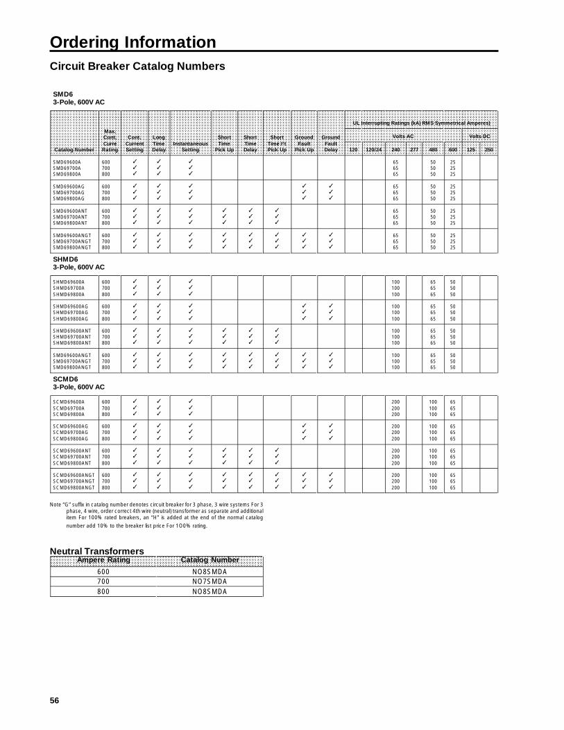
Ordering InformationCircuit Breaker Catalog Numbers
AAAAAAAAAAAAAAAAAAAAAAAAAAAA
AAAAAAAAAAAAAAAAAAAAA
AAAAAAAAAAAAAAAAAAAAAAAAAAAA
AAAAAAAAAAAAAAAAAAAAAAAAAAAA
AAAAAAA
AAAAAAAAAAAAAAAAAAAAAAAAAAAA
AAAAAAAAAAAAAAAAAAAAAAAAAAAA
AAAAAAAAAAAAAA
AAAAAAAAAAAAAAAAAAAAAAAAAAAA
AAAAAAA
AAAAAAAAAAAAAAAAAAAAAAAAAAAA
AAAAAAAAAAAAAAAAAAAAAAAAAAAA
AAAAAAA
AAAAAAAAAAAAAAAAAAAAAAAAAAAA
AAAAAAA
AAAAAAAAAAAAAAAAAAAAAAAAAAAA
AAAAAAAAAAAA
AAAAAAAAAAAA
AAAAAAAAAAAA
AAAAAAAAAAAA
AAAAAAAAAAAA
AAAAAA
AAAAAAAAAAAA
AAAAAAAAAAAA
AAAAAAAAAAAA
AAAAAAAAAAAA
AAA
AAAAAAAAAAAA
AAAAAA
AAAAAAAAAAAA
AAAAAAAAAAAA
AAAAAAAAAAAA
AAAAAAAAA
AAAAAAAAAAAA
AAAAAAAAA
AAAAAAAAAAAA
AAAAAAAAA
SMD63-Pole, 600V AC
Catalog Number
Max.Cont.CurreRating
Cont.CurrentSetting
LongTimeDelay
InstantaneousSetting
ShortTime
Pick Up
ShortTimeDelay
ShortTime I²tPick Up
GroundFault
Pick Up
GroundFaultDelay
UL Interrupting Ratings (kA) RMS Symmetrical Amperes)
Volts AC Volts DC
120 120/24 240 277 480 600 125 250
SMD69600ASMD69700ASMD69800A
600700800
✓✓✓
✓✓✓
✓✓✓
656565
505050
252525
SMD69600AGSMD69700AGSMD69800AG
600700800
✓✓✓
✓✓✓
✓✓✓
✓✓✓
✓✓✓
656565
505050
252525
SMD69600ANTSMD69700ANTSMD69800ANT
600700800
✓✓✓
✓✓✓
✓✓✓
✓✓✓
✓✓✓
✓✓✓
656565
505050
252525
SMD69600ANGTSMD69700ANGTSMD69800ANGT
600700800
✓✓✓
✓✓✓
✓✓✓
✓✓✓
✓✓✓
✓✓✓
✓✓✓
✓✓✓
656565
505050
252525
SHMD63-Pole, 600V AC
SHMD69600ASHMD69700ASHMD69800A
600700800
✓✓
✓
✓✓
✓
✓✓
✓
100100100
656565
505050
SHMD69600AGSHMD69700AGSHMD69800AG
600700800
✓✓
✓
✓✓
✓
✓✓
✓
✓✓
✓
✓✓
✓
100100100
656565
505050
SHMD69600ANTSHMD69700ANTSHMD69800ANT
600700800
✓✓✓
✓✓✓
✓✓✓
✓✓✓
✓✓✓
✓✓✓
100100100
656565
505050
SMD69600ANGTSMD69700ANGTSMD69800ANGT
600700800
✓✓✓
✓✓✓
✓✓✓
✓✓✓
✓✓✓
✓✓✓
✓✓✓
✓✓✓
100100100
656565
505050
SCMD63-Pole, 600V AC
SCMD69600ASCMD69700ASCMD69800A
600700800
✓
✓✓
✓
✓✓
✓
✓✓
200200200
100100100
656565
SCMD69600AGSCMD69700AGSCMD69800AG
600700800
✓✓
✓
✓✓
✓
✓✓
✓
✓✓
✓
✓✓
✓
200200200
100100100
656565
SCMD69600ANTSCMD69700ANTSCMD69800ANT
600700800
✓✓
✓
✓✓
✓
✓✓
✓
✓✓
✓
✓✓
✓
✓✓
✓
200200200
100100100
656565
SCMD69600ANGTSCMD69700ANGTSCMD69800ANGT
600700800
✓✓
✓
✓✓
✓
✓✓
✓
✓✓
✓
✓✓
✓
✓✓
✓
✓✓
✓
✓✓
✓
200200200
100100100
656565
Note “G” suffix in catalog number denotes circuit breaker for 3 phase, 3 wire systems For 3phase, 4 wire, order correct 4th wire (neutral) transformer as separate and additionalitem For 100% rated breakers, an “H” is added at the end of the normal catalog
number add 10% to the breaker list price For 1O0% rating.
Neutral Transformers
AAAAAAAA
AAAAAAAA
AAAAAAAA
AAAAAAAAAAAAAA
AAAAAAAA
AAAAAAAA
AAAAAAAmpere Rating Catalog Number
600 NO8SMDA700 NO7SMDA800 NO8SMDA

Ordering InformationCircuit Breaker Catalog Numbers
57
AAAAAAAAAAAAAAAAAAAAAAAAAAAA
AAAAAAAAAAAAAAAAAAAAA
AAAAAAAAAAAAAAAAAAAAAAAAAAAA
AAAAAAAAAAAAAAAAAAAAAAAAAAAA
AAAAAAA
AAAAAAAAAAAAAAAAAAAAAAAAAAAA
AAAAAAAAAAAAAAAAAAAAAAAAAAAA
AAAAAAAAAAAAAA
AAAAAAAAAAAAAAAAAAAAAAAAAAAA
AAAAAAA
AAAAAAAAAAAAAAAAAAAAAAAAAAAA
AAAAAAAAAAAAAAAAAAAAAAAAAAAA
AAAAAAA
AAAAAAAAAAAAAAAAAAAAAAAAAAAA
AAAAAAA
AAAAAAAAAAAAAAAAAAAAAAAAAAAA
AAAAAAAAAAAA
AAAAAAAAAAAA
AAAAAAAAAAAA
AAAAAAAAAAAA
AAAAAAAAAAAA
AAAAAA
AAAAAAAAAAAA
AAAAAAAAAAAA
AAAAAAAAAAAA
AAAAAAAAAAAA
AAA
AAAAAAAAAAAA
AAAAAA
AAAAAAAAAAAA
AAAAAAAAAAAA
AAAAAAAAAAAA
AAAAAAAAA
AAAAAAAAAAAA
AAAAAAAAA
AAAAAAAAAAAA
AAAAAAAAA
SND63-Pole, 600V AC
Catalog Number
Max.Cont.CurreRating
Cont.CurrentSetting
LongTimeDelay
InstantaneousSetting
ShortTime
Pick Up
ShortTimeDelay
ShortTime I²tPick Up
GroundFault
Pick Up
GroundFaultDelay
UL Interrupting Ratings (kA) RMS Symmetrical Amperes)
Volts AC Volts DC
120 120/24 240 277 480 600 125 250
SND69800ASND691000ASND691200A
80010001200
✓✓✓
✓✓✓
✓✓✓
656565
505050
252525
SND69800AGSND691000AGSND691200AG
80010001200
✓✓✓
✓✓✓
✓✓✓
✓✓✓
✓✓✓
656565
505050
252525
SND69800ANTSND691000ANTSND691200ANT
80010001200
✓✓✓
✓✓✓
✓✓✓
✓✓✓
✓✓✓
✓✓✓
656565
505050
252525
SND69800ANGTSND691000ANGTSND691200ANGT
80010001200
✓✓✓
✓✓✓
✓✓✓
✓✓✓
✓✓✓
✓✓✓
✓✓✓
✓✓✓
656565
505050
252525
SHND63-Pole, 600V AC
SHND69800ASHND691000ASHND691200A
80010001200
✓✓
✓
✓✓
✓
✓✓
✓
100100100
656565
505050
SHND69800AGSHND691000AGSHND691200AG
80010001200
✓✓
✓
✓✓
✓
✓✓
✓
✓✓
✓
✓✓
✓
100100100
656565
505050
SHND69800ANTSHND691000ANTSHND691200ANT
80010001200
✓✓✓
✓✓✓
✓✓✓
✓✓✓
✓✓✓
✓✓✓
100100100
656565
505050
SHND69800ANGTSHND691000ANGSHND691200ANG
80010001200
✓✓✓
✓✓✓
✓✓✓
✓✓✓
✓✓✓
✓✓✓
✓✓✓
✓✓✓
100100100
656565
505050
SCND63-Pole, 600V AC
SCND69800ASCND691000ASCND691200A
80010001200
✓
✓✓
✓
✓✓
✓
✓✓
200200200
100100100
656565
SCND69800AGSCND691000AGSCND691200AG
80010001200
✓✓
✓
✓✓
✓
✓✓
✓
✓✓
✓
✓✓
✓
200200200
100100100
656565
SCND69800ANTSCND691000ANTSCND691200ANT
80010001200
✓✓
✓
✓✓
✓
✓✓
✓
✓✓
✓
✓✓
✓
✓✓
✓
200200200
100100100
656565
SCND69800ANGTSCND691000ANGSCND691200ANG
80010001200
✓✓
✓
✓✓
✓
✓✓
✓
✓✓
✓
✓✓
✓
✓✓
✓
✓✓
✓
✓✓
✓
200200200
100100100
656565
Note: “G” suffix in catalog number denotes circuit breaker for 3 phase, 3 wire systems For 3 phase,4 wire, order correct 4th wire (neutral) transformer as separate and additional item. For 100%rated breakers, an “H” is added at the end of the normal catalog number add 10% to the breaker
list price for 100% rating.
Neutral Transformers (Not to be used on Sensitrip II)
AAAAAAAA
AAAAAAAA
AAAAAAAA
AAAAAAAAAAAAAA
AAAAAAAA
AAAAAAAA
AAAAAAAmpere Rating Catalog Number
800 N08SMDA1000 N10SNDA1200 N12SNDA

58
# Title
Shunt Trip
AAAAAAAAAAAA
AAAAAAAAAAAA
AAAAAAAAAAAA
AAAAAAAAAAAA
AAAAAAAAAAAA
AAAAAAAAAAAA
AAAAAAAAAAAA
AAAAAAAAAAAA
AAAAAAAAA
AAAAAAAAAAAA
AAAAAAAAAAAA
AAAAAAAAAAAA
AAAAAAAAAAAA
AAAAAAAAA
AAAAAAAAAAAA
AAAAAAAAAAAA
AAAAAAAAAAAA
AAAAAAAAAAAA
AAA
AAAAAAAAAAAA
AAAAAAAAAAAA
AAAAAAAAAAAA
AAAAAAAAAAAA
AAAAAAAAA
AAAAAAAAAAAA
AAAAAAAAAAAA
AAAAAAAAAAAA
AAAAAAAAAAAA
AAAAAAAAA
Control Voltage 1 Shunt Trip 1Shunt Trip and1 Auxiliary Switch
AC DC Catalog Number Catalog Number
120208240277480600
S01MN6S02MN6S03MN6S15MN6S04MN6S05MN6
S01MN64AS02MN64AS03MN64AS15MN64AS04MN64A
N/A
122448125250
S16MN6S07MN6S09MN6S11MN6S13MN6
S16MN64AS07MN64AS09MN64AS11MN64AS13MN64A
Undervoltage Trip
AAAAAAAAAAAA
AAAAAAAAAAAA
AAAAAAAAAAAA
AAA
AAAAAAAAAAAA
AAAAAAAAAAAA
AAAAAAAAAAAA
AAAAAA
AAAAAAAAAAAA
AAAAAAAAAAAA
AAAAAAAAAAAA
AAAAAA
AAAAAAAAAAAA
AAAAAAAAAAAA
AAAAAAAAAAAA
AAAAAA
AAAAAAAAAAAA
AAAAAAAAA
AAAAAAAAAAAA
AAAAAAAAAAAA
AAAAAAAAAAAA
AAAAAAAAAAAA
AAAAAAAAAAAA
AAAAAA
AAAAAAAAAAAA
AAAAAAAAAAAA
AAAAAAAAAAAA
AAAAAA
AAAAAAAAAAAA
AAAAAAAAAAAA
AAAAAAAAAAAA
AAAAAA
Control Voltage 1 Undervoltage Trip 1 Undervoltage Trip and1 Auxiliary Switch
1 Undervoltage Trip and2 Auxiliary Switches
AC DC Catalog Number Catalog Number Catalog Number
120208240277480600
U01MN6U02MN6U03MN6U15MN6U04MN6U06MN6
U01MN64AU02MN64AU03MN64AU15MN64AU04MN64A
N/A
U01MN64AAU02MN64AAU03MN64AAU15MN64AAU04MN64AA
N/A
2448
125250
U07MN6U09MN6U11MN6U13MN6
U07MN64AU09MN64AU11MN64AU13MN64A
U07MN64AAU09MN64AAU11MN64AAU13MN64AA
Auxiliary Switch
AAAAAAAA
AAAAAAAA
AAAAAAAA
AAAAAAAA
AAAAAAAA
AAAAAAAA
AAAAAAAA
AAAAAAAA
AAAAAAAAAAAAAA
AAAAAAAA
AAAAAAAA
AAAAAAAA
AAAAAA
AAAAAAAAAAAA
AAAAAAAAAAAA
AAAAAAAAAAAA
AAAAAAAAAAAA
AAA
AAAAAAAAAAAA
AAAAAAAAAAAA
AAAAAAAAAAAA
AAAAAAAAAAAA
AAAAAAAAA
AAAAAAAAAAAA
AAAAAAAAAAAA
AAAAAAAAAAAA
AAAAAAAAAAAA
AAAAAAAAA
Control Voltage 1 Auxiliary Switch 2 Auxiliary Switches
AC DC Catalog Number Catalog Number
120208240277480
A01MN64A01MN64A01MN64A01MN64A01MN64
A02MN64A02MN64A02MN64A02MN64A02MN64
2448125250
A01MN64A01MN64A01MN64A01MN64
A02MN64A02MN64A02MN64A02MN64
Bell Alarm Switch
AAAAAAAAAAAA
AAAAAAAAAAAA
AAAAAAAAAAAA
AAAAAAAAAAAA
AAAAAAAAAAAA
AAAAAAAAAAAA
AAAAAAAAAAAA
AAA
AAAAAAAAAAAA
AAAAAAAAAAAA
AAAAAAAAAAAA
AAA
AAAAAAAAAAAA
AAAAAAAAAAAA
AAAAAAAAAAAA
AAAAAA
AAAAAAAAAAAA
AAAAAAAAAAAA
AAAAAAAAAAAA
AAAAAAAAAAAA
AAA
AAAAAAAAAAAA
AAAAAAAAAAAA
AAAAAAAAAAAA
AAA
AAAAAAAAAAAA
AAAAAAAAAAAA
AAAAAAAAAAAA
AAA
AAAAAAAAAAAA
AAAAAAAAAAAA
AAAAAAAAAAAA
AAAAAA
Control Voltage 1 Alarm Switch 1 Alarm Switch and1 Auxiliary Switch
1 Alarm Switch and2 Auxiliary Switches
AC DC Catalog Number Catalog Number Catalog Number
120208240277480
B00MN64B00MN64B00MN64B00MN64B00MN64
B01MN64BB01MN64BB01MN64BB01MN64BB01MN64B
B02MN64BB02MN64BB02MN64BB02MN64BB02MN64B
2448125250
B00MN64B00MN64B00MN64B00MN64
B01MN64BB01MN64BB01MN64BB01MN64B
B02MN64BB02MN64BB02MN64BB02MN64B

Ordering InformationAdditional Accessories
59
Item Catalog No.
Extension Handle EX9
Mounting Screw Kit MSMN
Pressure Wire Connectors(4 pcs.) 250-500 MCM Cu/Al Kit (1) (3) TA4P8500(2 pcs.) 600-750 MCM Cu/Al Kit (1) (3)TA2K8750(3 pcs.) 250-700 MCM Cu/Al Kit (1) (3)TA3P8750(2 pcs.) #1 AWG-500 MCM Cu/Al TA2K500(3 pcs.) #I/0-500 MCM Cu/Al TA3K500(2 pcs.) #1 AWG-500 MCM Cu TC2K500(3 pcs.) #1 AWG-350 MCM Cu TC2K350
Compression Connectors CCM800CCN1200
Wire Connector Shield NDTS
Handle Blocking Device MN6BL
Padlocking Device MN6HPL
Rear Connecting Straps (Studs)Short Length RS5785Long Length RS5786
Plug-ln Adapters(2 Required per Breaker)Line Side (3-pole) PC5663Load Side (3-pole) PC5663
Steel Switchboard Mounting PlateUsed With Plug-ln Adapters PL5681
Mechanical Interlock Panel Mounted Ml5404 Plug-lnMounted Ml5404
Handle OperatorsRotary- Standard Depth
Complete Mechanism RHONSDHandle Only (1) RHOHBreaker Operator RHONBOStandard Length Shaft RHONSSD
(1) Each kit consists of (2) connectors or (3) connectors plus NDTS end barrier
Item Catalog No.
Handle Operators (continued)Rotary - Variable Depth
Complete Mechanism RHONVDHandle Only (1) RHOHBreaker Operator RHONBOVariable Length Shaft RHONSVD
Max-FlexTM Flange MountedComplete Mechanism FHONO48Handle Only(2) FHOHNBreaker Operator FHONBOCable Assembly (3) FHONCO48
Motor Operator120V AC (Hinged to the right) MOM N6120120V AC (Hinged to the left) MOMN6120L240V AC (Hinged to the right) MOMN6240240V AC (Hinged to the left) MOMN6240L
EnclosuresType 1 MND61Type 3R MND63Type 12 MND612
Door Latch MechanismLeft Side DKL2, DKL3Right Side DKR2, DKR3
Neutral Sensing Transformer600 Ampere Rating N06SMDA700 Ampere Rating N07SMDA800 Ampere Rating N08SMDA1000Ampere Rating N10SNDA1200 Ampere Rating N12SNDA
Test Kit TS-31
Time Current CurvesSMD6, SHMD6, SCMD6 TD 7208 REV 1SND6, SHND6, SCND6
(1) For 4x application use RHOH4 handle in place of RHOH.
(2) For 4x application use FHOHN4 handle in place of FHOHN.
(3) Optional cable length of 60 in. available, order FHONCO60.

60
UL Listings and File NumbersIndustry Specifications
AAAAAAAAAAAAAAAA
AAAAAAAAAAAAAAAA
AAAAAAAAAAAA
AAAAAAAAAAAAAAAA
AAAAAAAAAAAAAAAA
AAAA
AAAAAAAAAAAAAAAA
AAAAAAAAAAAAAAAA
AAAAAAAAAAAAI-T-E Items UL-489File
NumberCSA Report
Number
BreakersTerminal ConnectorsPlug-ln ConnectorsRear StudsAccessoriesShunt TripUndervoltage TripAux. SwitchBell Alarm SwitchEnclosures
E10848E23615 (sp.)
--
E69455E69455E69455E69455E10848
LR57039LR13077
--
LR13077LR13077LR13077LR13077
-
100 Percent Rating InformationMD-Frame MD-Frame breaker types are suitable for continu-ous operation at 100% of rating only if used in an enclosure orcubicle space 40.2 x 22.5 x 10.7 in.
The MD-Frame 100 percent rated breaker types SMD6,SHMD6 and SCMD6 are marked on the breaker label asfollows:
Wire ConnectorsCatalog Number Wire Range TorqueTA4P500 (4) 250-500 MCM Cu/AI 375 in. Ib.CCMB00 See instructions
For the correct 90 C wire size use Table 8.1 in UL 489according to the rating of the breaker.
National Fire Protection Assoc. (National Electrical Code).Federal Specification C-375B/GEN.Underwriters Laboratories, Inc. (UL 489).Canadian Standards Association (C22.2 No. 5).
ND-FrameND-Frame breaker types are suitable for continuous opera-tion at 100% of rating only if used in an enclosure or cubiclespace 60 x 22.5 x 10 in.
The ND-Frame 100 percent rated breaker types SND6,SHND6 and SCND6 are marked on the breaker label asfollows:
Wire ConnectorsCatalog Number Wire Range TorqueTA4P500 (4) 250-500 MCM Cu/AI 375 in. Ib.CCNB00 See instructions
For the correct 90 C wire size use Table 8.1 in UL 489according to the rating of the breaker.
Suitable for continuous operation at 100 percent of rating onlyif used in a ventilated enclosure or cubicle space 60 x 22.5 x10 in. Ventilation openings are 1.5x21 in. at bottom and 4.25x 21 in. at top and should be located at least 8 in. from endsof breaker.

Siemens Energy& Automation, Inc.3333 State Bridge Rd.Alpharetta, GA 30201
Bulletin SIB2.7-8 (New) (c) 1990 Siemens Energy & Automation, Inc.