i/a series system ista-*bp* instruction manualpzip.ru/downloads/pepperl+fuchs/tmdoc0941d_eng.pdf ·...
TRANSCRIPT
B0700BMREV E
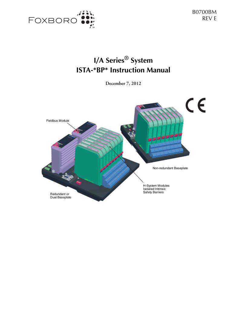
I/A Series® System
ISTA-*BP* Instruction Manual
December 7, 2012
Non-redundant Baseplate
H-System Modules
Fieldbus Module
Redundant or
Isolated IntrinsicSafety Barriers
Dual Baseplate

ii
Invensys, Foxboro, and I/A Series are trademarks of Invensys plc, its subsidiaries, and affiliatesAll other brand names may be trademarks of their respective owners.
Copyright 2004 - 2012 Invensys Systems Inc.All rights reserved
iii
Contents
Figures................................................................................................................................... vii
Tables................................................................................................................................... viii
Preface.................................................................................................................................... 1
Revision Information ................................................................................................................ 1
Compliance with European Directives ...................................................................................... 2
Safety Considerations ................................................................................................................ 2Explanation of Symbols Used ............................................................................................... 2User Responsibilities ............................................................................................................. 3General Safety Requirements ................................................................................................ 3Intended Use......................................................................................................................... 4Installation of ISTA-*BP* in a General-Purpose (Unclassified) Area...................................... 5Installation of ISTA-*BP* within a Hazardous Classified Location........................................ 6Fault Elimination ................................................................................................................. 6CE Marking .......................................................................................................................... 7Delivery ................................................................................................................................ 7Included with Delivery ......................................................................................................... 7Marking ............................................................................................................................... 7
Reference Documents ............................................................................................................... 8
1. Overview ......................................................................................................................... 11
Functional and Environmental Considerations ....................................................................... 13Invensys DIN Rail Mounted Fieldbus Modules, Control Processors, and Termination Assemblies .............................................................................................. 13Pepperl+Fuchs H-System Modules ..................................................................................... 13ISTA-*BP*s Heat Dissipation and Power Consumption .................................................... 13Power Supply Loading ....................................................................................................... 15
Baseplate Implementation ....................................................................................................... 16Module Fieldbus Cable (shielded twisted pairs)................................................................... 17ISTA-*BP* Baseplate Replacement...................................................................................... 18
Replacing an ISTA-*BP* Baseplate in the First Position ................................................. 19Replacing an ISTA-*BP* Baseplate in the Second (or Higher) Position ......................... 20Replacing a Baseplate in the Third (Not the Last) Position ............................................ 21Replacing a Baseplate in the Last Position ..................................................................... 21Adding a Baseplate to the Last Position .......................................................................... 22
Intrinsic Safety Baseplate ......................................................................................................... 23ISTA-*BP* ......................................................................................................................... 23Fieldbus Modules ............................................................................................................... 23H-System Modules ............................................................................................................. 23
B0700BM – Rev E Contents
iv
Coding of H-System Modules ............................................................................................. 24Channel Assignment ........................................................................................................... 25Fault Monitor ..................................................................................................................... 26HART Protocol................................................................................................................... 27Description of ISTA-*BP*s.................................................................................................. 29Non-Redundant (Single) .................................................................................................... 29
ISTA-201-BPAI – 4 to 20 mA Input Interface Board, HART-Compatible ................... 29ISTA-201-BPAI-FD - 4 to 20 mA Input Interface Board, HART-Compatible, Line Fault Detection ...................................................................... 30ISTA-201-BPTI - RTD/Thermocouple/mV Interface Board ........................................ 30ISTA-204-BPAIO - 4 to 20 mA I/0 Interface Board, HART-Compatible ..................... 30
Mounting Station A to D: ........................................................................................ 30Mounting Station E to H: ........................................................................................ 30
ISTA-204-BPAIO-FD - 4 to 20 mA I/0 Interface Board, Line Fault Detection, HART-Compatible ........................................................................................................ 31
Mounting Station A to D: ........................................................................................ 31Mounting Station E to H: ........................................................................................ 31
ISTA-204-BPTIO - RTD/Thermocouple/mV Input, 4 to 20 mA Output Interface Board .............................................................................. 31
Mounting Station A to D: ........................................................................................ 31Mounting Station E to H: ........................................................................................ 31
ISTA-204-BPTIO-FD RTD/thermocouple/mV Input, 4 to 20 mA Output Interface Board, HART-Compatible, Line Fault Detection ............ 32
Mounting Station A to D: ........................................................................................ 32Mounting Station E to H: ........................................................................................ 32
ISTA-207b-BPDI-FD - Voltage Monitor/Contact Sense Input Interface Board ............ 32ISTA-211-BPAI - 4 to 20 mA Input Interface Board, HART-Compatible .................... 32ISTA-211-BPAI-3W - 4 to 20 mA Input Interface Board, HART-Compatible ............. 32ISTA-211-BPTI - RTD/Thermocouple/mV Input Interface Board................................ 33ISTA-214-BPHI - HART-Communication, 4 to 20 mA Input Interface Board ............ 33ISTA-214-BPHI-FD - HART-Communication, 4 to 20 mA Input Interface Board, Line Fault Detection ............................................... 33ISTA-215-BPHO-FD - HART Communication 4 to 20 mA Output Interface Board, Line Fault Detection ............................................ 33ISTA-217-BPDI-FD - Discrete Input Interface Board, Line Fault Detection ................ 33ISTA-237-BPAO - 4 to 20 mA Output Interface Board................................................. 34ISTA-237-BPAO-FD - 4 to 20 mA Output Interface Board, HART-Compatible, Line Fault Detection ..................................................................... 34ISTA-241c-BPDIO - Discrete I/O Interface Board ....................................................... 34
Mounting station A to D: ......................................................................................... 34Mounting station E to H: ......................................................................................... 34
ISTA-241c-BPDIO-FD - Discrete I/O Interface Board, Line Fault Detection .............. 34Mounting Station A to D: ........................................................................................ 34Mounting Station E to H: ........................................................................................ 34
ISTA-242-BPDO - Externally Sourced Discrete Output Interface Board ....................... 35ISTA-242-BPDO-FD - Externally Sourced Discrete Output Interface Board, Line Fault Detection ...................................................................................................... 35
Redundant .......................................................................................................................... 36
Contents B0700BM – Rev E
v
ISTA-216-BPHI-R - Redundant 4 to 20 mA Input Interface Board, HART Communication ................................................................................................ 36ISTA-216-BPHI-FD-R - Redundant 4 to 20 mA Input Interface Board, HART Communication, Line Fault Detection .......................................................................... 36ISTA-218-BPHO-FD-R - Redundant 4 to 20 mA Output Interface, HART Communication, Board, Line Fault Detection.................................................... 37ISTA-237-BPAO-R - Redundant 4 to 20 mA Output Interface Board .......................... 37ISTA-237-BPAO-FD-R - Redundant 4 to 20 mA Output Interface Board, Line Fault Detection, HART-Compatible ..................................................................... 37
Dual .................................................................................................................................... 38ISTA-201-BPAI-D - 4 to 20 mA Input Interface Board, HART-Compatible ................ 38ISTA-201-BPAI-FD-D - 4 to 20 mA Input Interface Board, HART-Compatible, Line Fault Detection ..................................................................... 38ISTA-201-BPTI-D - RTD/Thermocouple/mV Interface Board ..................................... 39ISTA-204-BPAIO-D - 4 to 20 mA I/O Interface Board, HART-Compatible ............... 39
Mounting Station A, B and E, F: .............................................................................. 39Mounting Station C, D and G, H: ........................................................................... 39
ISTA-204-BPAIO-FD-D - 4 to 20 mA I/O Interface Board, HART-Compatible, Line Fault Detection ..................................................................... 39
Mounting Station A, B and E, F: .............................................................................. 39Mounting Station C, D and G, H: ........................................................................... 39
ISTA-204-BPTIO-D - RTD/Thermocouple/mV Input, 4 to 20 mA Output Interface Board ............................................................................... 40
Mounting Station A, B and E, F: .............................................................................. 40Mounting Station C, D and G, H: ........................................................................... 40
ISTA-204-BPTIO-FD-D - RTD/Thermocouple/mV Input, 4 to 20 mA Output Interface Board, HART-Compatible, Line Fault Detection ........... 40
Mounting Station A, B and E, F: .............................................................................. 40Mounting Station C, D and G, H: ........................................................................... 40
ISTA-214-BPHI-D - HART-Communication, 4 to 20 mA Input Interface Board .................................................................................. 41ISTA-214-BPHI-FD-D - HART-Communication, 4 to 20 mA Input Interface Board, Line Fault Detection ............................................... 41ISTA-215-BPHO-FD-D - HART-Communication, 4 to 20 mA Output Interface Board, Line Fault Detection ............................................ 41
2. Enclosure Installation ...................................................................................................... 43
I/O Cabinet ............................................................................................................................ 43
Preinstallation Procedures ....................................................................................................... 45Unloading .......................................................................................................................... 45Unpacking .......................................................................................................................... 45Subsystem Power Checks ................................................................................................... 45
3. Equipment Installation.................................................................................................... 47
Baseplate Installation ............................................................................................................... 47
Installation of Modules (FBM, H-System) .............................................................................. 48Fieldbus Modules ............................................................................................................... 48
B0700BM – Rev E Contents
vi
H-System Modules.............................................................................................................. 50
Power Supply, Mounting and Installation ............................................................................... 51Foxboro Power Supply (FPS400-24) .................................................................................. 51
Dimensions – Nominal ................................................................................................. 52Clearance – Nominal...................................................................................................... 53
Factory Mains Power Connections to the Power Supply ..................................................... 55Baseplate Power Supply Cabling.......................................................................................... 56
Foxboro Power Supply FPS400-24 ................................................................................ 56ISTA-*BP* Power Cable Connections ............................................................................ 58
24 V DC Power Distribution Cable Group P0972RN .............................................. 60ISTA-*BP* HART Multiplexer Connection................................................................... 61
ISTA-*BP* ID Switch Setting and Addressing..................................................................... 62
Ethernet, Fiber Optic, and Module Bus Cable Runs in Hazardous Areas ................................ 65
4. Field Signal Connections ................................................................................................. 67
Field Wiring to ISTA-*BP* Connections ................................................................................ 67Field (Signal) Wires ............................................................................................................ 69
Appendix A. H-System Modules Specifications without FBMs ........................................... 71
Module Physical Characteristics .............................................................................................. 71Single FBM version of ISTA -*BP* ................................................................................ 71Dual or redundant FBM versions of ISTA -*BP* ........................................................... 71
Power Supply .......................................................................................................................... 72
Module Temperature, Relative Humidity, and Contamination ............................................... 72
Module Vibration ................................................................................................................... 72
Module Heat Dissipation and Power Consumption ................................................................ 72
Electromagnetic Compatibility (EMC) ................................................................................... 72European EMC Directive 2004/180/EC ............................................................................ 72
Protection Classes Provided by Housing ................................................................................. 73
vii
Figures
1-1. Layout of an ISTA-*BP* System ................................................................................. 12Non-Redundant .......................................................................................................... 16Dual or Redundant ..................................................................................................... 16
1-2. Non-Redundant, Dual and Redundant Baseplate ....................................................... 161-3. ISTA-*BP* Interconnection Using Shielded Twisted-Pair Cable ................................. 171-4. Normal Connection .................................................................................................... 181-5. Bypass Connection First Baseplate .............................................................................. 191-6. Bypass Connection for Second (Or Higher Number) ISTA-*BP* Baseplate ................ 201-7. Fault Output ............................................................................................................... 261-8. Diagram of HART Mux Installation ........................................................................... 281-9. ISTA-2XXy-BPYY Non-Redundant Baseplate ............................................................ 291-10. ISTA-2XXy-BPYY-R Redundant ................................................................................ 361-11. ISTA-2XXy-BPYY-D Dual ......................................................................................... 382-1. I/O Cabinet Layout ..................................................................................................... 443-1. Required Support for ISTA-*BP* with Horizontal DIN Rail Mounting ..................... 473-2. Mounting of ISTA-*BP* on DIN Rail ........................................................................ 483-3. Mounting of FBM on ISTA-*BP* ............................................................................... 493-4. Mounting of H-System Modules on ISTA-*BP* ......................................................... 503-5. Foxboro DIN Rail Mounted FBM Subsystem Equipment Power Supply .................... 513-6. Foxboro Power Supply FPS400-24 Dimensions .......................................................... 523-7. Foxboro Power Supply FPS400-24 Clearance Requirements ....................................... 533-8. Foxboro Power Supply FPS400-24 Wall Mount Bracket Screw Hole Dimensions ...... 543-9. Input and Output Power Connector from FPS400-24 to
Baseplate Connector for Version P0922YU ................................................................. 563-10. Input and Output Power Connector from FPS400-24 to
Baseplate Connector for Version P0922YC ................................................................. 573-11. FPS400-24 Power Supply Wiring ............................................................................... 583-12. Power Supply Cable Connections at ISTA-*BP* ......................................................... 593-13. Recommended Cabling Solution (P0972RN Cable Group) ........................................ 603-14. ID Switches ................................................................................................................. 623-15. Addressing a Non-Redundant, Dual or Redundant ISTA-*BP* .................................. 633-16. Addressing ISTA-*BP* and FCMs .............................................................................. 644-1. Field wiring to ISTA-*BP* Connections showing the terminal blocks per module ...... 674-2. Connecting a H-System Module ................................................................................. 68A-1. Dimensions of FBM versions ...................................................................................... 71
viii
Tables
1-1. Power Consumption ................................................................................................... 131-2. Coding of Interface Board ........................................................................................... 241-3. Channel Assignment ................................................................................................... 251-4. Pinout Assignment for 37-pin HART Connector ....................................................... 283-1. FPS400-24 Input/Output Connectors (P0922YU) ..................................................... 563-2. FPS400-24 Input/Output Connectors (P0922YC) ..................................................... 573-3. P0972RN Cable Group .............................................................................................. 603-4. Setting the Baseplate ID Switches for Non-Redundant ISTA-*BP* Boards ................. 633-5. Setting the FBM ID Switch for Non-Redundant ISTA-*BP* Boards .......................... 633-6. Setting the Baseplate ID Switches for Dual or Redundant ISTA-*BP* Boards ............. 643-7. Setting the FBM ID Switch for Redundant ISTA-*BP* Boards ................................... 644-1. H-System Basic Properties ........................................................................................... 694-2. Protection Classes ....................................................................................................... 73
1
Preface
This document describes all aspects of the ISTA-*BP* subsystem, including:
♦ Installation
♦ Configuration
♦ Operation
It is intended for use by process engineering, operations, and maintenance personnel. In addition, the manual contains introductory instructions for selecting the correct mounting plate based on a specified 200 Series Fieldbus Module, and it helps in assigning a mounting baseplate and Fieldbus Module for a process measurement and control task. For more information on Fieldbus Modules, isolator modules and HART communication, consult the specific manual to which reference is made.
NOTE
You must read “Safety Considerations” on page 2 carefully before planning, installation, and commissioning.
Revision InformationFor Revision E, the following changes were made to this document:
Preface
♦ Updated section "General Safety Requirements" on page 3.
♦ Updated section "Intended Use" on page 4.
♦ Updated section "Installation of ISTA-*BP* in a General-Purpose (Unclassified) Area" on page 5.
♦ Updated section "Installation of ISTA-*BP* within a Hazardous Classified Location" on page 6.
♦ Updated section "Fault Elimination" on page 6.
♦ Changed section "CE Marking" on page 7.
Chapter 1, “Overview”:
♦ Updated section "H-System Modules" on page 23.
♦ Updated section "Description of ISTA-*BP*s" on page 29.
Chapter 2, “Enclosure Installation”:
♦ Updated section "I/O Cabinet" on page 43.
Appendix A, “H-System Modules Specification without FBMs”:
♦ Updated section "Electromagnetic Compatibility (EMC)" on page 72.
B0700BM – Rev E Preface
2
Compliance with European Directives
All installation instructions shall be followed for system to comply with mandatory European Directives 94/9/EC for equipment and protective systems intended for use in potentially explosive atmospheres, 2004/108/EC for Electromagnetic Compatibility.
Safety Considerations
Explanation of Symbols UsedSafe use of this product depends largely upon proper installation and maintenance by you, the user. This manual provides the information needed to properly install and maintain the ISTA-*BP* subsystem. Where applicable, appropriate CAUTION, WARNING and NOTE statements are included in the text of this document.
A CAUTION statement warns against potential hazards or unsafe practices which could result in product or property damage; for example:
CAUTION!
Do not attempt to force the adjustment screw beyond its limit, or the threads may be damaged.
A WARNING statement warns of a level of hazard which could result in personal injury; for example:
WARNING!
Adjacent components and circuits have shock hazard potential that can cause personal injury. Use insulated tools and observe all safety precautions.
WARNING!
To prevent explosion, DO NOT install or remove cables, wiring, modules, or other replaceable system components in hazardous locations. Remove power to the equipment at the source or ensure that the atmosphere is non-explosive before installing or removing any electrical component.
A NOTE statement draws your attention to important information.
NOTE
The safety instructions must be read carefully before installation and commissioning.
Preface B0700BM – Rev E
3
User ResponsibilitiesThe user must become familiar with the device and must have read and understood the manual before installation and commissioning. Various processes and instructions in this manual require special preventive measures to ensure the safety of employees.
CAUTION!
Jobs must only be performed on or with the device by persons who are authorized to do so, based on their training and qualifications, and who have read and understood the manual. In addition, these persons must be authorized by the operator to do this!
CAUTION!
In addition to this manual, you must also observe the requirements for installation in areas subject to the danger of explosion.
General Safety Requirements
WARNING!
For use as associated apparatus in accordance with EN 60079-11 or ANSI/ISA 12.02.01, the declarations of conformity, control drawings and Federal Requirements for those setting up the equipment must be observed.
WARNING!
The devices must not be repaired, changed or manipulated. If there is a defect, the product must be returned to manufacturer.
B0700BM – Rev E Preface
4
Intended UseISTA-*BP*s (Intrinsic Safety Termination Assembly - Base Plate) are intended to be used for applications requiring protection of process control signals from or to approved field devices in hazardous (classified) locations. Galvanic isolators approved as intrinsically safe associated apparatus are mounted on the baseplate and are protective barriers against dangerous electrical energy entering the hazardous areas. These isolators are Pepperl+Fuchs’ H-System Modules (HiD = High Density).
Data sheets for the H-System Modules and the associated baseplates must be considered as part of this instruction manual/user’s guide. The appropriate intrinsic safety control drawings and EC declarations of conformity information must also be considered as part of this guide.
Laws or regulations concerning the use or planned purpose must be observed.
Devices that are operated in general purpose applications must not thereafter be operated in electrical systems that are connected to hazardous areas.
WARNING!
Protection of operating personnel and the system is not guaranteed if the device is not used in accordance with its intended purpose.
WARNING!
Mounting plate ISTA-*BP* must only be operated by trained professionals in accordance with available device documentation (instruction manual, data sheet, and certificate of conformity).
EC-Type Examination Certificate number: ZELM 10 ATEX 0446 X. EC-Type Examination Certificate, Declaration of Conformity and instructions have to be observed. This information can be found under www.pepperl-fuchs.com.
CSA Examination Certificate number: 1545160 (LR 66529-18). CSA Examination Certificate, control drawings and instructions have to be observed. This information can be found under www.pepperl-fuchs.com.
Preface B0700BM – Rev E
5
Installation of ISTA-*BP* in a General-Purpose (Unclassified) Area
♦ ISTA-*BP* mounting plates are designed for protection class IP20 in accordance with IEC/EN 60529. To ensure IP20 all modules must be fitted.
♦ ISTA-*BP* mounting plates are designed for use in pollution degree 2 and overvoltage category II in accordance with IEC/EN 60664-1. If used in areas with higher pollution degree, the devices need to be protected accordingly.
♦ The intrinsically safe circuits of the H-System Modules that are fitted, can be routed into hazardous areas. Special care must be taken in this case to ensure reliable separation from all non-intrinsically safe circuits. The installation of the intrinsically safe circuits is to be conducted in accordance with the relevant installation regulations.
♦ The corresponding entity parameters for the field devices and the isolated modules associated with it as defined for the purpose of explosion protection must be observed when interconnecting intrinsically safe field devices with the intrinsically safe circuits of ISTA-*BP* mounting plates (proof of intrinsic safety). IEC/EN 60079-14 or NEC 500 should be observed in this regard.
♦ Intrinsically safe circuits which have been operated with circuits of other type of protection must not be used as intrinsically safe circuits afterwards.
♦ The installation instructions in accordance with IEC/EN 60079-14 or NEC 500 must be observed.
♦ EC Type Examination Certificate of conformity must be observed. It is especially important to maintain any special conditions that may be indicated.
B0700BM – Rev E Preface
6
Installation of ISTA-*BP* within a Hazardous Classified Location Category 3 (Zone 2)
Class I, Division 2, Groups A, B, C and D; T4 @ + 60 °C
Class I, Zone 2, Ex nA IIC T4; Ta = 60 °C
Class I, Zone 2, AEx nA IIC T4; Ta = 60 °C
♦ Mounting plate ISTA-*BP* and the corresponding modules must only be used in Zone 2 if the corresponding conformity information of a named location or a declaration of conformity from the manufacturer is on file.
♦ For information on whether these requirements are met, please refer to the individual data sheets for the ISTA-*BP* mounting plate and the related H-System Modules (see www.pepperl-fuchs.com) and the Invensys Foxboro 200 Series Fieldbus Module Product Specification Sheets.
♦ The devices should be installed in an enclosure to IP54 or better, in accordance with IEC/EN 60529. An explanation of the IP code is in the Appendix A.
♦ The intrinsically safe circuits of the H-System galvanic isolators can be routed into hazardous areas. These are indicated by the blue terminal blocks. Special care must be taken in this case to ensure reliable separation from all non-intrinsically safe circuits. The installation of the intrinsically safe circuits is to be conducted in accordance with the relevant installation regulations.
♦ The corresponding entity parameters for the field device and the isolated modules associated with it as defined for the purpose of explosion protection must be observed when interconnecting intrinsically safe field devices with the intrinsically safe circuits of ISTA-*BP* mounting plates (proof of intrinsic safety). IEC/EN 60079-14 or NEC 500 should be observed in this regard.
♦ The installation instructions in accordance with IEC/EN 60079-14 or NEC 500 must be observed.
♦ Intrinsically safe circuits which have been operated with circuits of other type of protection must not be used as intrinsically safe circuits afterwards.
♦ EC Type Examination Certificate and the zone 2 declaration must be observed. It is especially important to maintain any special conditions that may be indicated.
Fault EliminationNo changes must be made to devices that are operated in connection with areas subject to the danger of explosion. The devices must not be repaired, changed or manipulated. If there is a defect, the product must be returned to manufacturer.
Preface B0700BM – Rev E
7
CE MarkingPepperl+Fuchs GmbH
Lilienthalstrasse 200, 68307 Mannheim, Germany
ISTA-*BP*
ZELM 10 ATEX 0446 X
¬ II (1) G [Ex ia] IIC, ¬ II (1) D [Ex ia] IIIC, ¬ II (M1) [Ex ia] I
PF10ATEX1707 X
¬ II 3 G Ex nA IIC T4 Gc
For further information please refer to www.pepperl-fuchs.com.
DeliveryMake certain the contents are not damaged. If there is damage, notify the post office or shipping company and contact the Customer Satisfaction Center at Invensys Systems, Inc.
Compare the contents of the delivery package with your order and the delivery documents:
♦ Quantity supplied
♦ Device type and version in accordance with the type plate
♦ Accessories (manual, etc.)
Retain the original packaging in case the items have to be stored or further transported at a later date.
If you have any questions, contact Invensys Systems, Inc. Customer Satisfaction Center.
Included with Delivery♦ Base plate
♦ H-System Modules
♦ Plug for power supply (4 pieces)
♦ Plug for fault messages (1 piece)
MarkingThe marking that identifies ISTA-*BP* is broken down as follows: ISTA-2XXx-BPYY-(VV)-Z
2XXx: FBM number - example FBM207b
YY: Function - such as: AI, AO, DI, DO, TI, TIO
VV: FD for fault evaluation (only if H-System Module supports the function)
3W for 3-wire transmitter
Z: R for redundant (two FBMs); D for dual (two FBMs)
B0700BM – Rev E Preface
8
Reference Documents
In addition to the information presented herein, you should be familiar with the following I/A Series and Pepperl+Fuchs documents:
♦ DIN Rail Mounted Subsystem User’s Guide (B0400FA)
♦ Pepperl+Fuchs Series H-System System Description and Catalog (see www.pepperl-fuchs.com)
♦ Pepperl+Fuchs HiDMux2700 HART Multiplexer Manual (see www.pepperl-fuchs.com)
♦ Control Processor 60 and Control Processor 60S Installation and Maintenance (B0400FB)
♦ Control Processor 270 (CP270) Integrated Control Software Concepts (B0700AG)
♦ Enclosures and Mounting Structures - Site Planning and Installation User’s Guide (B0700AS)
♦ Field Control Processor 270 (FCP270) User’s Guide (B0700AR)
♦ HART Communication Interface Module (FBM214/215/216/218) User’s Guide (B0400FF)
♦ Integrated Control Block Descriptions (B0193AX)
♦ Integrated Control Configurator (B0193AV)
♦ Integrated Control Software Concepts (B0193AW)
♦ Power, Earthing (Grounding), EMC and CE Compliance (B0700AU)
♦ Process Operations and Displays (B0193MM, pre-V8.0 systems)
♦ Process Operations and Displays (B0700BN, V8.0 and later systems)
♦ Site Planning (B0193AB)
♦ Software Installation (Solaris® Platform) (B0193JG)
♦ System Definition: A Step-by-Step Procedure (B0193WQ)
♦ System Equipment Installation (B0193AC)
♦ System Management Displays (B0193JC and associated Help screens)
♦ Z-Module Control Processor 270 (ZCP270) User’s Guide (B0700AN)
Most are available on the I/A Series Electronic Documentation CD-ROM (K0173TQ). The latest revisions may also be available through the Global Customer Support Center (Global CSC) at http://support.ips.invensys.com.
Preface B0700BM – Rev E
9
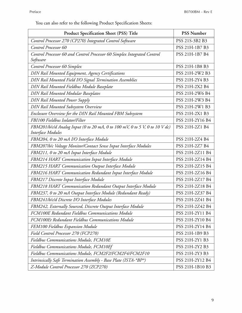
You can also refer to the following Product Specification Sheets:
Product Specification Sheet (PSS) Title PSS Number
Control Processor 270 (CP270) Integrated Control Software PSS 21S-3B2 B3
Control Processor 60 PSS 21H-1B7 B3
Control Processor 60 and Control Processor 60 Simplex Integrated Control Software
PSS 21H-1B7 B4
Control Processor 60 Simplex PSS 21H-1B8 B3
DIN Rail Mounted Equipment, Agency Certifications PSS 21H-2W2 B3
DIN Rail Mounted Field I/O Signal Termination Assemblies PSS 21H-2Y4 B3
DIN Rail Mounted Fieldbus Module Baseplate PSS 21H-2X2 B4
DIN Rail Mounted Modular Baseplates PSS 21H-2W6 B4
DIN Rail Mounted Power Supply PSS 21H-2W3 B4
DIN Rail Mounted Subsystem Overview PSS 21H-2W1 B3
Enclosure Overview for the DIN Rail Mounted FBM Subsystem PSS 21H-2X1 B3
FBI100 Fieldbus Isolator/Filter PSS 21H-2Y16 B4
FBM201/b/c/d Analog Input (0 to 20 mA, 0 to 100 mV, 0 to 5 V, 0 to 10 V dc) Interface Modules
PSS 21H-2Z1 B4
FBM204, 0 to 20 mA I/O Interface Module PSS 21H-2Z4 B4
FBM207/b/c Voltage Monitor/Contact Sense Input Interface Modules PSS 21H-2Z7 B4
FBM211, 0 to 20 mA Input Interface Module PSS 21H-2Z11 B4
FBM214 HART Communication Input Interface Module PSS 21H-2Z14 B4
FBM215 HART Communication Output Interface Module PSS 21H-2Z15 B4
FBM216 HART Communication Redundant Input Interface Module PSS 21H-2Z16 B4
FBM217 Discrete Input Interface Module PSS 21H-2Z17 B4
FBM218 HART Communication Redundant Output Interface Module PSS 21H-2Z18 B4
FBM237, 0 to 20 mA Output Interface Module (Redundant Ready) PSS 21H-2Z37 B4
FBM241/b/c/d Discrete I/O Interface Modules PSS 21H-2Z41 B4
FBM242, Externally Sourced, Discrete Output Interface Module PSS 21H-2Z42 B4
FCM100E Redundant Fieldbus Communications Module PSS 21H-2Y11 B4
FCM100Et Redundant Fieldbus Communications Module PSS 21H-2Y10 B4
FEM100 Fieldbus Expansion Module PSS 21H-2Y14 B4
Field Control Processor 270 (FCP270) PSS 21H-1B9 B3
Fieldbus Communications Module, FCM10E PSS 21H-2Y1 B3
Fieldbus Communications Module, FCM10Ef PSS 21H-2Y2 B3
Fieldbus Communications Module, FCM2F2/FCM2F4/FCM2F10 PSS 21H-2Y3 B3
Intrinsically Safe Termination Assembly - Base Plate (ISTA-*BP*) PSS 21H-2Y12 B4
Z-Module Control Processor 270 (ZCP270) PSS 21H-1B10 B3

B0700BM – Rev E Preface
10
11
1. Overview
This chapter gives an overview of the Intrinsic Safety Baseplate (ISTA-*BP*) for the Invensys Foxboro 200 Series FBMs used with I/A Series Control Systems
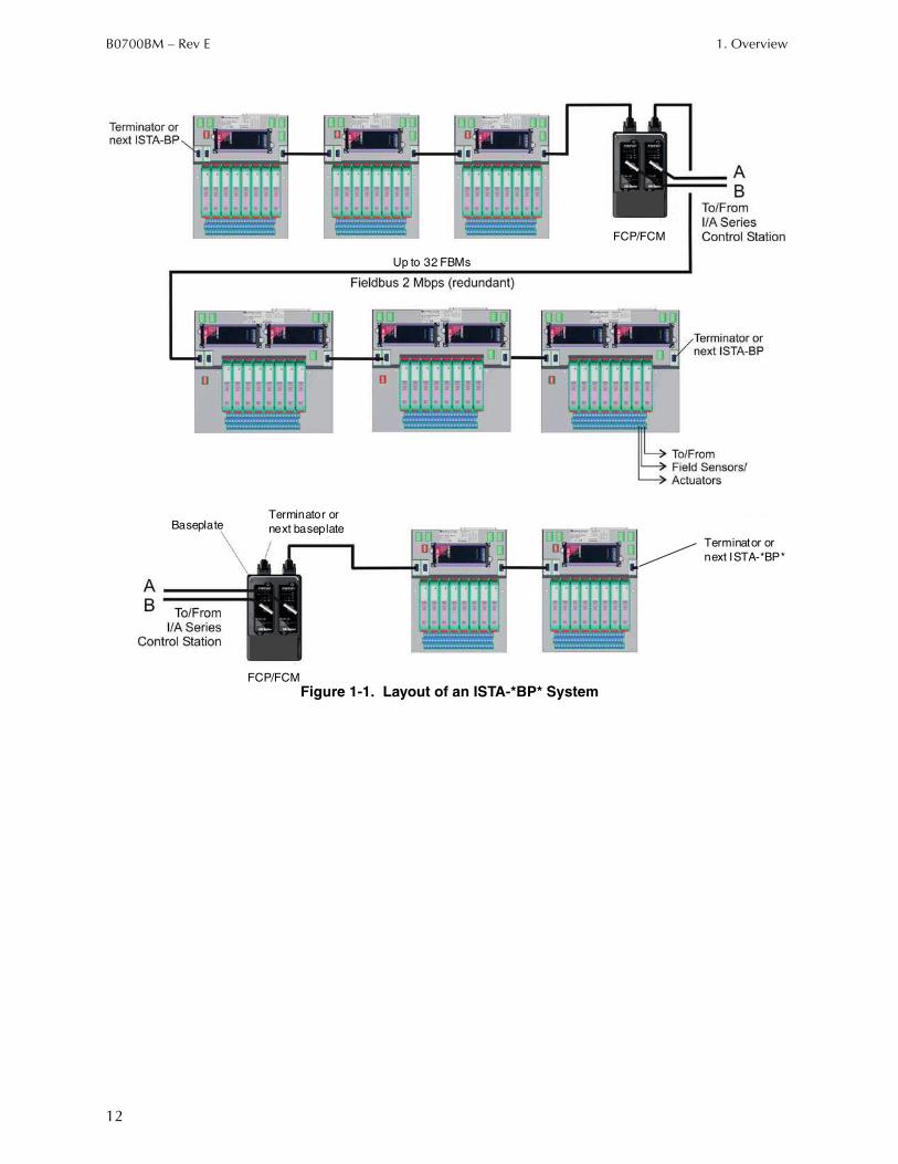
The ISTA-*BP* fitted with one or two FBM’s provides a reliable, high speed communication interface between a control processor (for example the I/A Series control station) and field I/O sensors and actuators. It incorporates innovative equipment packaging, and the use of fiber optic and/or coaxial cabling between Fieldbus Communication Modules (FCMs) to allow local or remote distribution of process I/O points.
♦ Baseplate – The baseplate provides a base for mounting of one or two FBMs and eight H-System Modules. Up to 30 baseplates can be interconnected to provide mounting for up to 30 FBMs per FCM or redundant FCM pair.
♦ H-System Modules - Intrinsically safe isolators galvanically separate signals between sensors and actuators on the field side and Fieldbus Modules (FBM) on the bus side.
♦ Fieldbus Modules (FBMs) – FBMs serve as an interface between the intrinsic safety isolators H-System Module and the I/A Series control station (via Fieldbus Communication Module and the Ethernet trunk Fieldbus). They perform necessary data conversion, providing full support for analog measurement, discrete sensing, and analog or discrete control and digital communication.
♦ Fieldbus Communications Modules (FCMs) - FCMs are located on a separate Two Position Baseplate. They form the interface between the control system (for example the I/A Series control station) and the FBMs. FCMs can access a maximum of 32 FBMs per segment.
B0700BM – Rev E 1. Overview
12
Figure 1-1. Layout of an ISTA-*BP* System
FCP/FCM
Terminator or
next ISTA-*BP*
Up to 32 FBMs
Terminator or
next baseplateBaseplate
FCP/FCM
1. Overview B0700BM – Rev E
13
Functional and Environmental Considerations
The actual amount of power required for a DIN rail mounted subsystem depends on the number and types of components installed: 200 Series Modules, ISTA-*BP*s, and H-System Modules.
Invensys DIN Rail Mounted Fieldbus Modules, Control Processors, and Termination AssembliesFor information on functional and environmental specifications on 200 Series Modules, and termination assemblies, refer to the relevant Product Specification Sheets (PSSs) posted on the Invensys Global Customer Satisfaction Center web page at http://support.ips.invensys.com.
Pepperl+Fuchs H-System ModulesFor the functional and environmental specifications relating to the associated H-System Modules, see www.pepperl-fuchs.com.
ISTA-*BP*s Heat Dissipation and Power Consumption
NOTE
A high installation density of ISTA-*BP*s and power supplies requires forced air ventilation in the cabinet. The necessary protection class of the cabinet must be taken into consideration in designing the ventilation!
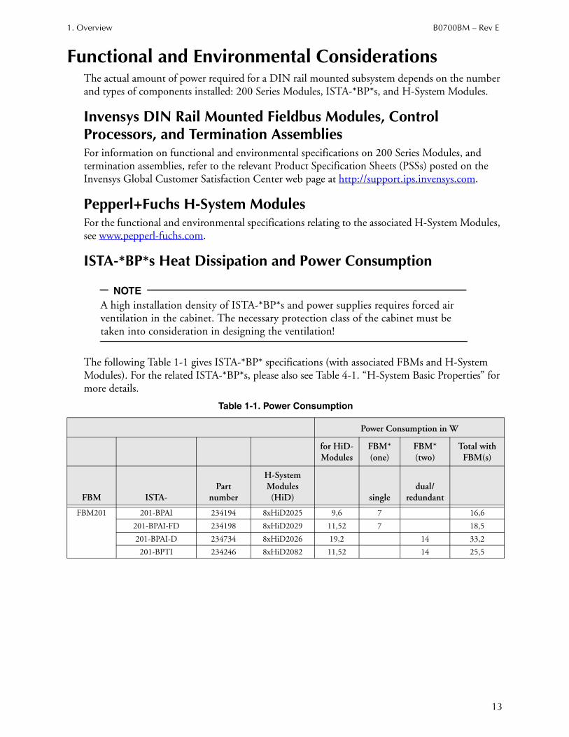
The following Table 1-1 gives ISTA-*BP* specifications (with associated FBMs and H-System Modules). For the related ISTA-*BP*s, please also see Table 4-1. “H-System Basic Properties” for more details.
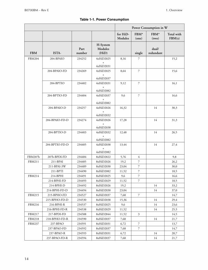
Table 1-1. Power Consumption
Power Consumption in W
for HiD-Modules
FBM*(one)
FBM*(two)
Total with FBM(s)
FBM ISTA-Part
number
H-System Modules (HiD) single
dual/ redundant
FBM201 201-BPAI 234194 8xHiD2025 9,6 7 16,6
201-BPAI-FD 234198 8xHiD2029 11,52 7 18,5
201-BPAI-D 234734 8xHiD2026 19,2 14 33,2
201-BPTI 234246 8xHiD2082 11,52 14 25,5
B0700BM – Rev E 1. Overview
14
FBM204 204-BPAIO 234252 4xHiD2025+
4xHiD2031
8,16 7 15,2
204-BPAIO-FD 234269 4xHiD2025+
4xHiD2037
8,64 7 15,6
204-BPTIO 234402 4xHiD2031+
4xHiD2082
9,12 7 16,1
204-BPTIO-FD 234404 4xHiD2037+
4xHiD2082
9,6 7 16,6
204-BPAIO-D 234257 4xHiD2026+
4xHiD2032
16,32 14 30,3
204-BPAIO-FD-D 234274 4xHiD2026+
4xHiD2038
17,28 14 31,3
204-BPTIO-D 234403 4xHiD2032+
4xHiD2082
12,48 14 26,5
204-BPTIO-FD-D 234405 4xHiD2038+
4xHiD2082
13,44 14 27,4
FBM207b 207b-BPDI-FD 234484 8xHiD2822 5,76 4 9,8
FBM211 211-BPAI 234485 8xHiD2026 19,2 7 26,2
211-BPAI-3W 234489 8xHiD2030 23,04 7 30,0
211-BPTI 234490 8xHiD2082 11,52 7 18,5
FBM214 214-BPHI 234491 8xHiD2025 9,6 7 16,6
214-BPHI-FD 234493 8xHiD2029 11,52 7 18,5
214-BPHI-D 234492 8xHiD2026 19,2 14 33,2
214-BPHI-FD-D 234494 8xHiD2030 23,04 14 37,0
FBM215 215-BPHO-FD 234527 8xHiD2037 7,68 7 14,7
215-BPHO-FD-D 234530 8xHiD2038 15,36 14 29,4
FBM216 216-BPHI-R 234537 8xHiD2025 9,6 14 23,6
216-BPHI-FD-R 234538 8xHiD2029 11,52 14 25,5
FBM217 217-BPDI-FD 234588 8xHiD2844 11,52 3 14,5
FBM218 218-BPHO-FD-R 234590 8xHiD2037 7,68 14 21,7
FBM237 237-BPAO 234591 8xHiD2031 6,72 7 13,7
237-BPAO-FD 234592 8xHiD2037 7,68 7 14,7
237-BPAO-R 234593 8xHiD2031 6,72 14 20,7
237-BPAO-FD-R 234594 8xHiD2037 7,68 14 21,7
Table 1-1. Power Consumption
Power Consumption in W
for HiD-Modules
FBM*(one)
FBM*(two)
Total with FBM(s)
FBM ISTA-Part
number
H-System Modules (HiD) single
dual/ redundant

1. Overview B0700BM – Rev E
15
*) Please also see individual Foxboro PSS for the respective FBM for possible changes.
Power Supply LoadingFor specifications on the DIN rail mounted FPS400-24 power supplies (P0922YU or P0922YC), refer to DIN Rail Mounted Power Supply (PSS 21H-2W3 B4).
The FPS400-24 can also be used as a field power supply to power external field devices. However, for system integrity field devices and DIN rail baseplates should not be powered from the same FPS400-24.
Based on the specifications above, the number of ISTA-*BP*s that can be connected to a single power supply can be estimated.
FBM241c 241c-BPDIO 234595 4xHiD2822+
4xHiD2872
12,48 5 17,5
241c-BPDIO-FD 234596 4xHiD2822+
4xHiD2872
15,36 5 20,4
FBM242 242-BPDO 234599 8xHiD2876 19,2 3 22,2
242-BPDO-FD 234601 8xHiD2872 24,96 3 28,0
Table 1-1. Power Consumption
Power Consumption in W
for HiD-Modules
FBM*(one)
FBM*(two)
Total with FBM(s)
FBM ISTA-Part
number
H-System Modules (HiD) single
dual/ redundant
B0700BM – Rev E 1. Overview
16
Baseplate Implementation
Communication between the ISTA-*BP* with the 200 Series FBMs and the I/A Series control station is performed over the 2 Mbps Fieldbus with either FCP270 control stations, or ZCP270s/CP60s via FCM devices. The FBMs automatically accept communication from either communication path of the redundant Ethernet trunk Fieldbus. Thus, if one path fails, communication is not interrupted.
A Fieldbus segment consists of two Fieldbus Communication Modules (FCM) and a maximum of 32 ISTA-*BP*s with one FBM or a maximum of 16 redundant or dual ISTA-*BP*s, since each FBM of a ISTA-*BP* has its own address assigned to it.
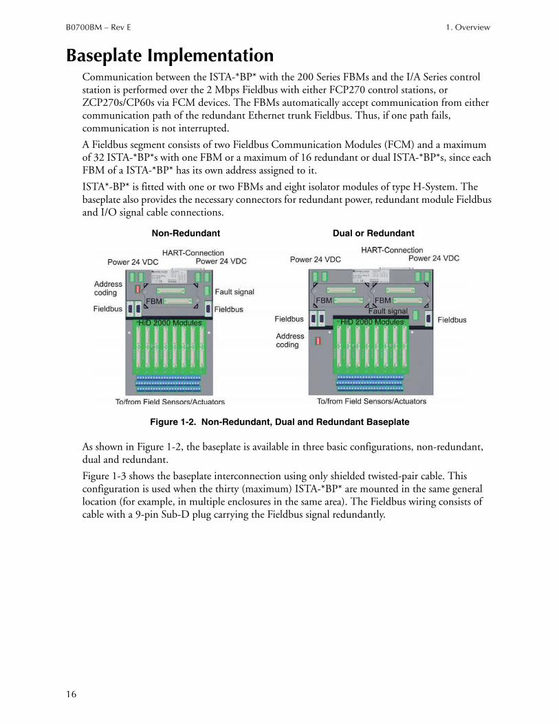
ISTA*-BP* is fitted with one or two FBMs and eight isolator modules of type H-System. The baseplate also provides the necessary connectors for redundant power, redundant module Fieldbus and I/O signal cable connections.
Figure 1-2. Non-Redundant, Dual and Redundant Baseplate
As shown in Figure 1-2, the baseplate is available in three basic configurations, non-redundant, dual and redundant.
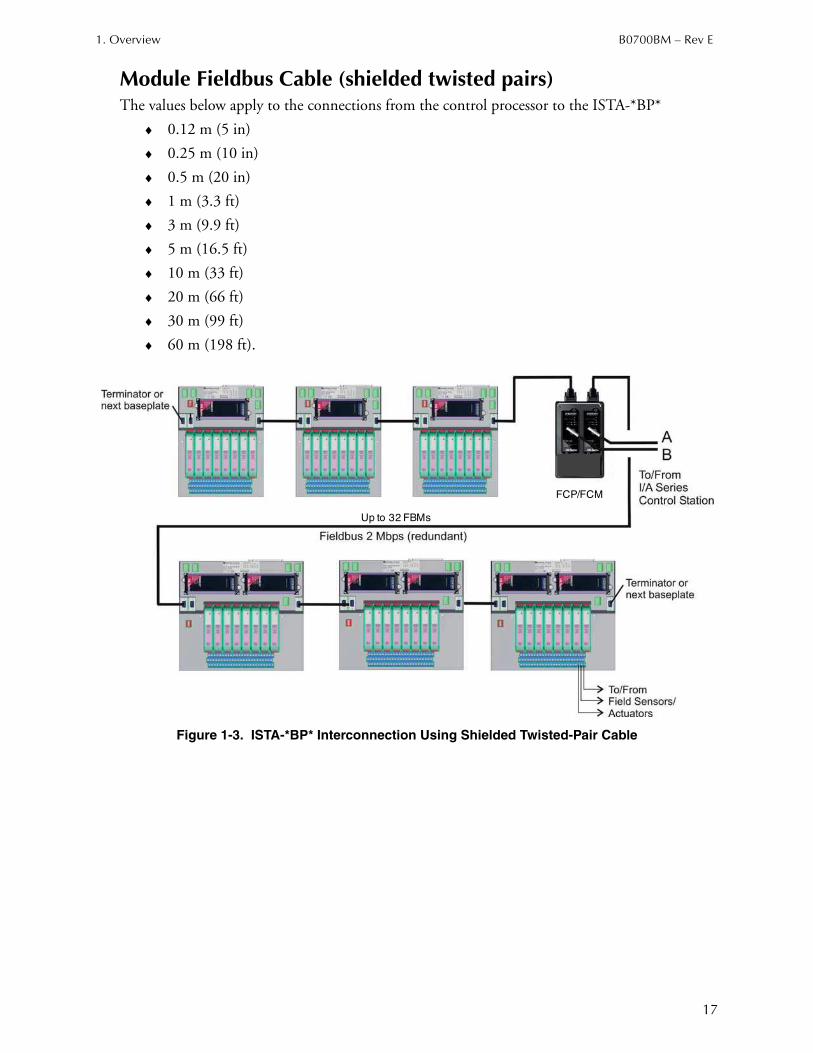
Figure 1-3 shows the baseplate interconnection using only shielded twisted-pair cable. This configuration is used when the thirty (maximum) ISTA-*BP* are mounted in the same general location (for example, in multiple enclosures in the same area). The Fieldbus wiring consists of cable with a 9-pin Sub-D plug carrying the Fieldbus signal redundantly.
Non-Redundant Dual or Redundant
1. Overview B0700BM – Rev E
17
Module Fieldbus Cable (shielded twisted pairs)The values below apply to the connections from the control processor to the ISTA-*BP*
♦ 0.12 m (5 in)
♦ 0.25 m (10 in)
♦ 0.5 m (20 in)
♦ 1 m (3.3 ft)
♦ 3 m (9.9 ft)
♦ 5 m (16.5 ft)
♦ 10 m (33 ft)
♦ 20 m (66 ft)
♦ 30 m (99 ft)
♦ 60 m (198 ft).
Figure 1-3. ISTA-*BP* Interconnection Using Shielded Twisted-Pair Cable
FCP/FCM
Up to 32 FBMs
B0700BM – Rev E 1. Overview
18
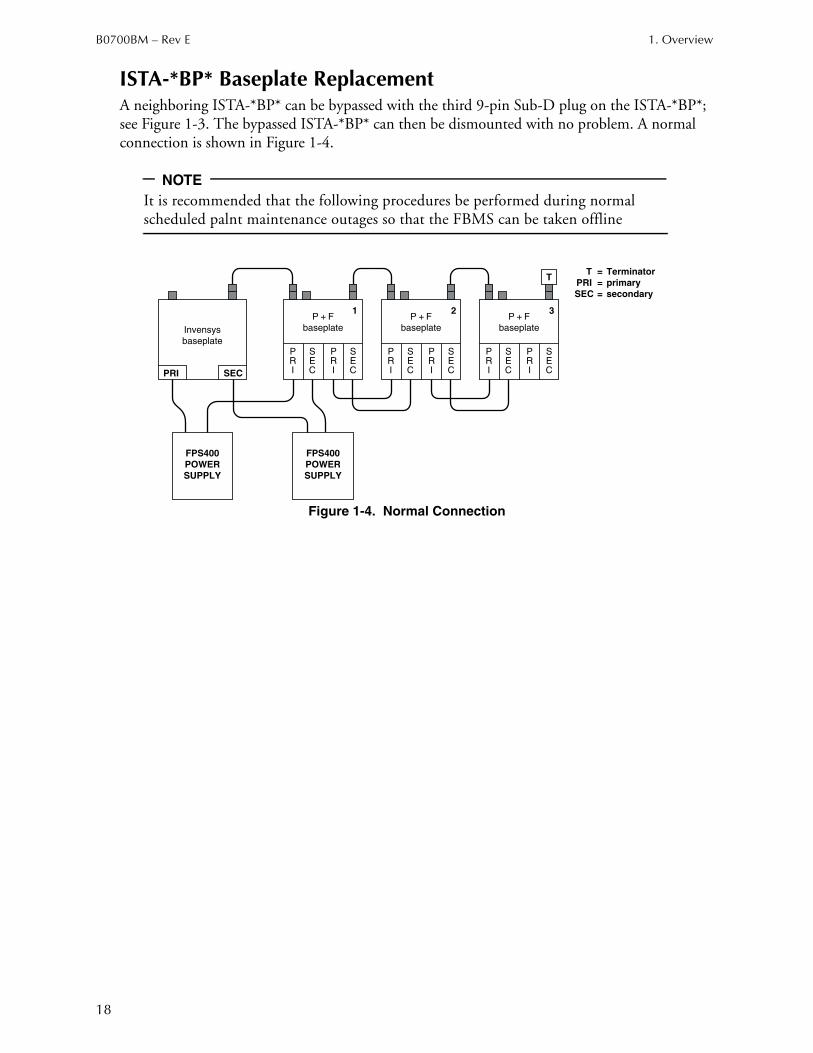
ISTA-*BP* Baseplate ReplacementA neighboring ISTA-*BP* can be bypassed with the third 9-pin Sub-D plug on the ISTA-*BP*; see Figure 1-3. The bypassed ISTA-*BP* can then be dismounted with no problem. A normal connection is shown in Figure 1-4.
NOTE
It is recommended that the following procedures be performed during normal scheduled palnt maintenance outages so that the FBMS can be taken offline
Figure 1-4. Normal Connection
PRI SEC
T
PRI
SEC
PRI
SEC
PRI
SEC
PRI
SEC
PRI
SEC
PRI
SEC
1 2 3
Invensys
baseplate
P + F
baseplate
P + F
baseplate
P + F
baseplate
FPS400
POWER
SUPPLY
FPS400
POWER
SUPPLY
T = Terminator
PRI = primary
SEC = secondary

1. Overview B0700BM – Rev E
19
Replacing an ISTA-*BP* Baseplate in the First PositionTo replace the first ISTA-*BP* Baseplate (next to the Invensys Foxboro Baseplate) without modules on other baseplates going off line, proceed as follows:
1. Assemble the Fieldbus Bypass Cable (shown in Figure 1-5) using:
♦ 2 Terminator/splitters
♦ 3 Fieldbus cables, and
♦ A gender changer connector.
Figure 1-5. Bypass Connection First Baseplate
2. Switch FB “A” and FB “B” terminators ON at the T/S that attaches to the Invensys Foxboro baseplate. Make sure that the Time Strobe (TS “A” and TS “B”) switches are OFF.
3. Switch all the FB and TS switches OFF at the other T/S.
4. Install the fieldbus bypass cable as shown in Figure 1-5.
5. Install the power bypass cables as shown in Figure 1-5. When installing power bypass cables, ensure that the primary power goes to the power source and the secondary power goes to the secondary source.
6. Disconnect the power and fieldbus cables and Terminator from first ISTA-*BP* baseplate.
7. Disconnect the field wiring from first ISTA-*BP* baseplate.
8. Remove the first ISTA-*BP* baseplate from DIN rail and replace it with new baseplate.
9. Remove the DIN FBMs from the replaced baseplate and place them onto the new baseplate
10. Connect the field wiring to new baseplate.
PRI SEC
T/S
T/S
T
PRI
SEC
PRI
SEC
PRI
SEC
PRI
SEC
PRI
SEC
PRI
SEC
1 2 3
Invensys
baseplate
P + F
baseplate
P + F
baseplate
P + F
baseplate
FPS400
POWER
SUPPLY
FPS400
POWER
SUPPLY
9 pin gender changer
Power Bypass Cable
T/S = Terminator/Splitter
T = Terminator
PRI = primary
SEC = secondaryFieldbus "A" connectors
Fieldbus Bypass Cable
B0700BM – Rev E 1. Overview
20
11. Connect the terminator, power and fieldbus cables to new baseplate.
12. Remove the power bypass cables.
13. Remove the fieldbus bypass cable.
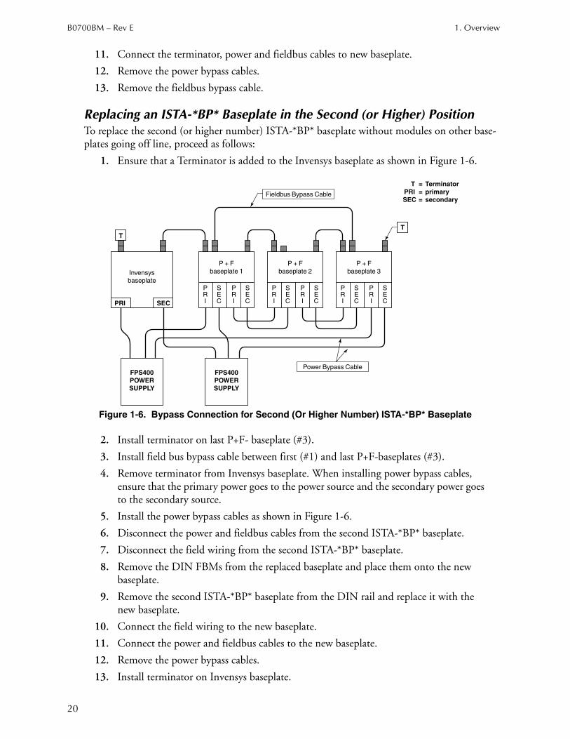
Replacing an ISTA-*BP* Baseplate in the Second (or Higher) PositionTo replace the second (or higher number) ISTA-*BP* baseplate without modules on other base-plates going off line, proceed as follows:
1. Ensure that a Terminator is added to the Invensys baseplate as shown in Figure 1-6.
Figure 1-6. Bypass Connection for Second (Or Higher Number) ISTA-*BP* Baseplate
2. Install terminator on last P+F- baseplate (#3).
3. Install field bus bypass cable between first (#1) and last P+F-baseplates (#3).
4. Remove terminator from Invensys baseplate. When installing power bypass cables, ensure that the primary power goes to the power source and the secondary power goes to the secondary source.
5. Install the power bypass cables as shown in Figure 1-6.
6. Disconnect the power and fieldbus cables from the second ISTA-*BP* baseplate.
7. Disconnect the field wiring from the second ISTA-*BP* baseplate.
8. Remove the DIN FBMs from the replaced baseplate and place them onto the new baseplate.
9. Remove the second ISTA-*BP* baseplate from the DIN rail and replace it with the new baseplate.
10. Connect the field wiring to the new baseplate.
11. Connect the power and fieldbus cables to the new baseplate.
12. Remove the power bypass cables.
13. Install terminator on Invensys baseplate.
PRI SEC
T
T
PRI
SEC
PRI
SEC
PRI
SEC
PRI
SEC
PRI
SEC
PRI
SEC
Invensys
baseplate
P + F
baseplate 1
P + F
baseplate 2
P + F
baseplate 3
FPS400
POWER
SUPPLY
FPS400
POWER
SUPPLY
Fieldbus Bypass Cable
Power Bypass Cable
T = Terminator
PRI = primary
SEC = secondary
1. Overview B0700BM – Rev E
21
14. Remove terminator from last P&F baseplate (#3).
15. Remove the terminator from the Invensys Foxboro baseplate.
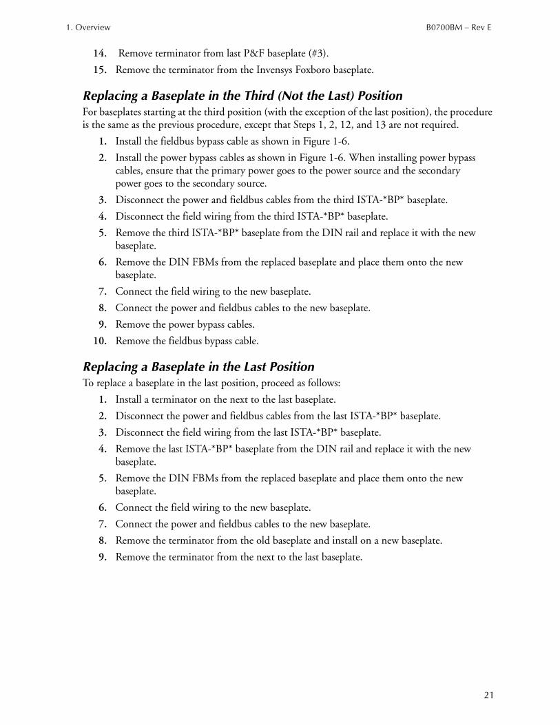
Replacing a Baseplate in the Third (Not the Last) PositionFor baseplates starting at the third position (with the exception of the last position), the procedure is the same as the previous procedure, except that Steps 1, 2, 12, and 13 are not required.
1. Install the fieldbus bypass cable as shown in Figure 1-6.
2. Install the power bypass cables as shown in Figure 1-6. When installing power bypass cables, ensure that the primary power goes to the power source and the secondary power goes to the secondary source.
3. Disconnect the power and fieldbus cables from the third ISTA-*BP* baseplate.
4. Disconnect the field wiring from the third ISTA-*BP* baseplate.
5. Remove the third ISTA-*BP* baseplate from the DIN rail and replace it with the new baseplate.
6. Remove the DIN FBMs from the replaced baseplate and place them onto the new baseplate.
7. Connect the field wiring to the new baseplate.
8. Connect the power and fieldbus cables to the new baseplate.
9. Remove the power bypass cables.
10. Remove the fieldbus bypass cable.
Replacing a Baseplate in the Last PositionTo replace a baseplate in the last position, proceed as follows:
1. Install a terminator on the next to the last baseplate.
2. Disconnect the power and fieldbus cables from the last ISTA-*BP* baseplate.
3. Disconnect the field wiring from the last ISTA-*BP* baseplate.
4. Remove the last ISTA-*BP* baseplate from the DIN rail and replace it with the new baseplate.
5. Remove the DIN FBMs from the replaced baseplate and place them onto the new baseplate.
6. Connect the field wiring to the new baseplate.
7. Connect the power and fieldbus cables to the new baseplate.
8. Remove the terminator from the old baseplate and install on a new baseplate.
9. Remove the terminator from the next to the last baseplate.

B0700BM – Rev E 1. Overview
22
Adding a Baseplate to the Last PositionTo add a baseplate at the end, proceed as follows:
1. Install a terminator on the next to last baseplate.
2. Remove the terminator from the last baseplate.
3. Add a new baseplate and connect the power and fieldbus cables.
4. Add a terminator to the new baseplate and remove the terminator that was installed in Step 1.
1. Overview B0700BM – Rev E
23
Intrinsic Safety Baseplate
ISTA-*BP*ISTA-*BP*s are intrinsic safety interfaces consisting of a baseplate and eight intrinsic safety isolators. One or two Foxboro Fieldbus Modules (FBM) can be mounted on the ISTA-*BP* baseplate but are not included with the ISTA-*BP*. A broad range of ISTA-*BP* types are available to provide support for various analog measurement, discrete sensing, and analog or discrete control requirements.
Fieldbus Modules The Fieldbus Modules (FBM) perform the signal conversion required to interface the electrical signals to/from the field devices to the I/A Series control station. Light-emitting diodes (LEDs) incorporated into the front of each module provide visual status indications of the Fieldbus Module functions. The FBMs plug onto the baseplate by means of their two connectors, and each is fastened in place by two hex screws.
H-System ModulesH-System Modules (galvanic isolators) provide intrinsically safe circuits to field devices. Each H-System Module must be matched to an approved field device using Entity Parameters.
NOTE
The ISTA*-BP* must be fitted with eight H-System Modules and the individual H-System Modules must be chosen to match the FBM type; see “Fieldbus Modules” on page 23.
H-System Modules are plugged into the connectors on the baseplate. Press down on the two tabs on either side of the module to lock the module into the baseplate.
WARNING!
Only Pepperl+Fuchs H-System modules which are approved for direct inseration into termiantion board must be used.
B0700BM – Rev E 1. Overview
24
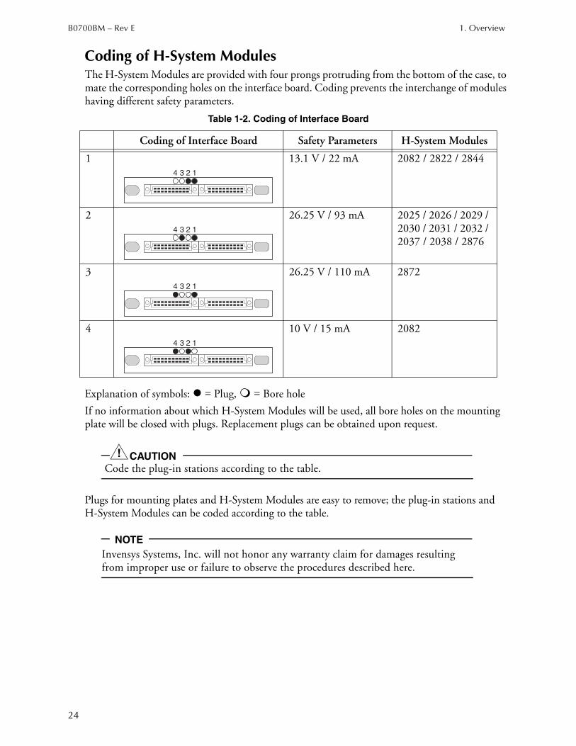
Coding of H-System ModulesThe H-System Modules are provided with four prongs protruding from the bottom of the case, to mate the corresponding holes on the interface board. Coding prevents the interchange of modules having different safety parameters.
Explanation of symbols: = Plug, = Bore hole
If no information about which H-System Modules will be used, all bore holes on the mounting plate will be closed with plugs. Replacement plugs can be obtained upon request.
CAUTION!
Code the plug-in stations according to the table.
Plugs for mounting plates and H-System Modules are easy to remove; the plug-in stations and H-System Modules can be coded according to the table.
NOTE
Invensys Systems, Inc. will not honor any warranty claim for damages resulting from improper use or failure to observe the procedures described here.
Table 1-2. Coding of Interface Board
Coding of Interface Board Safety Parameters H-System Modules
1 13.1 V / 22 mA 2082 / 2822 / 2844
2 26.25 V / 93 mA 2025 / 2026 / 2029 / 2030 / 2031 / 2032 / 2037 / 2038 / 2876
3 26.25 V / 110 mA 2872
4 10 V / 15 mA 2082
1234
1234
1234
1234
1. Overview B0700BM – Rev E
25
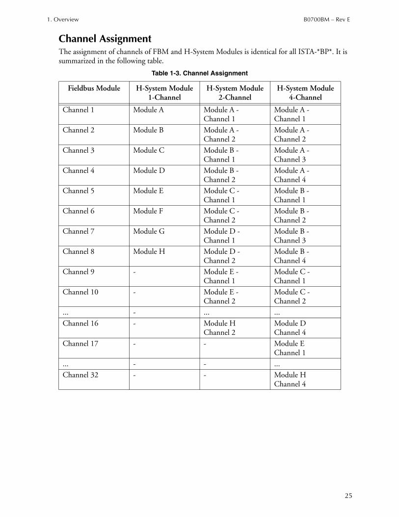
Channel AssignmentThe assignment of channels of FBM and H-System Modules is identical for all ISTA-*BP*. It is summarized in the following table.
Table 1-3. Channel Assignment
Fieldbus Module H-System Module1-Channel
H-System Module2-Channel
H-System Module4-Channel
Channel 1 Module A Module A -Channel 1
Module A -Channel 1
Channel 2 Module B Module A -Channel 2
Module A -Channel 2
Channel 3 Module C Module B -Channel 1
Module A -Channel 3
Channel 4 Module D Module B -Channel 2
Module A -Channel 4
Channel 5 Module E Module C -Channel 1
Module B -Channel 1
Channel 6 Module F Module C -Channel 2
Module B -Channel 2
Channel 7 Module G Module D -Channel 1
Module B -Channel 3
Channel 8 Module H Module D -Channel 2
Module B -Channel 4
Channel 9 - Module E -Channel 1
Module C -Channel 1
Channel 10 - Module E -Channel 2
Module C -Channel 2
... - ... ...
Channel 16 - Module HChannel 2
Module DChannel 4
Channel 17 - - Module EChannel 1
... - - ...
Channel 32 - - Module HChannel 4
B0700BM – Rev E 1. Overview
26
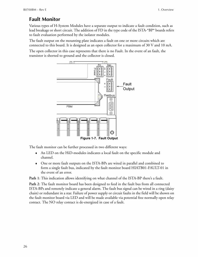
Fault MonitorVarious types of H-System Modules have a separate output to indicate a fault condition, such as lead breakage or short circuit. The addition of FD in the type code of the ISTA-*BP* boards refers to fault evaluation performed by the isolator modules.
The fault output on the mounting plate indicates a fault on one or more circuits which are connected to this board. It is designed as an open collector for a maximum of 30 V and 10 mA.
The open collector in this case represents that there is no Fault. In the event of an fault, the transistor is shorted to ground and the collector is closed.
Figure 1-7. Fault Output
The fault monitor can be further processed in two different ways:
♦ An LED on the HiD-modules indicates a local fault on the specific module and channel.
♦ One or more fault outputs on the ISTA-BPs are wired in parallel and combined to form a single fault bus, indicated by the fault monitor board HIATB01-FAULT-01 in the event of an error.
Path 1: This indication allows identifying on what channel of the ISTA-BP there’s a fault.
Path 2: The fault monitor board has been designed to feed in the fault bus from all connected ISTA-BPs and remotely indicate a general alarm. The fault bus signal can be wired in a ring (daisy chain) or redundant in a star. Failure of power supply or circuit faults in the field will be shown on the fault monitor board via LED and will be made available via potential free normally open relay contact. The NO relay contact is de-energized in case of a fault.
1. Overview B0700BM – Rev E
27
HART ProtocolCurrent repeater H-System Modules of the type HiD2025, HiD2026, HiD2029, HiD2030 and driver/repeater modules HiD2037 and HiD2038 transfer the HART protocol bi-directionally for HART devices.
There are two paths for transmitting the HART protocol to the HART device:
1) HART-capable FBMs.
2) Connection to a Pepperl+Fuchs H-System HART-Multiplexer solution using the HiD Mux 2700.
NOTE
Do not use a HART-Multiplexer path simultaneously in connection with HART-capable FBMs as multiple master devices may cause communication errors.
Path 1: HART-capable FBMs such as 214, 215, 216 and 218 transfer the digital HART bi-directional from the I/A Series Fieldbus to the HART devices. This way of HART-communication is processed through the FBMs.
Path: 2: All ISTA-*BP*s used with analog I/O signals offer a 37-Pin Sub-D Connector on the baseplate allowing to connect to the H-system HART Multiplexer solution HiD Mux 2700. The HiD Mux 2700 supports up to 32 channels and can be placed onto two different HART communication boards. The HIATB01-HART-2x16 (for dual boards supporting 2x 16 channels) or HIATB01-HART-4x08 (for simplex or redundant boards supporting 4x 8 channels).
This interface offers HART-communication to HART enabled field devices even if the FBMs are not HART-capable. Therefore the ISTA-BPs are equipped with communication resistors, allowing the HART signal to be “picked up” by the HART multiplexer and transmitted over a dedicated RS 485 network to a workstation for use with compatible HART management software. Figure 1-8 shows a typical setup of such a HART multiplexer application interfacing the HART-Connector on the ISTA-BP and the HART communication board with a system cable. Also, please see www.pepperl-fuchs.com for more information.
B0700BM – Rev E 1. Overview
28
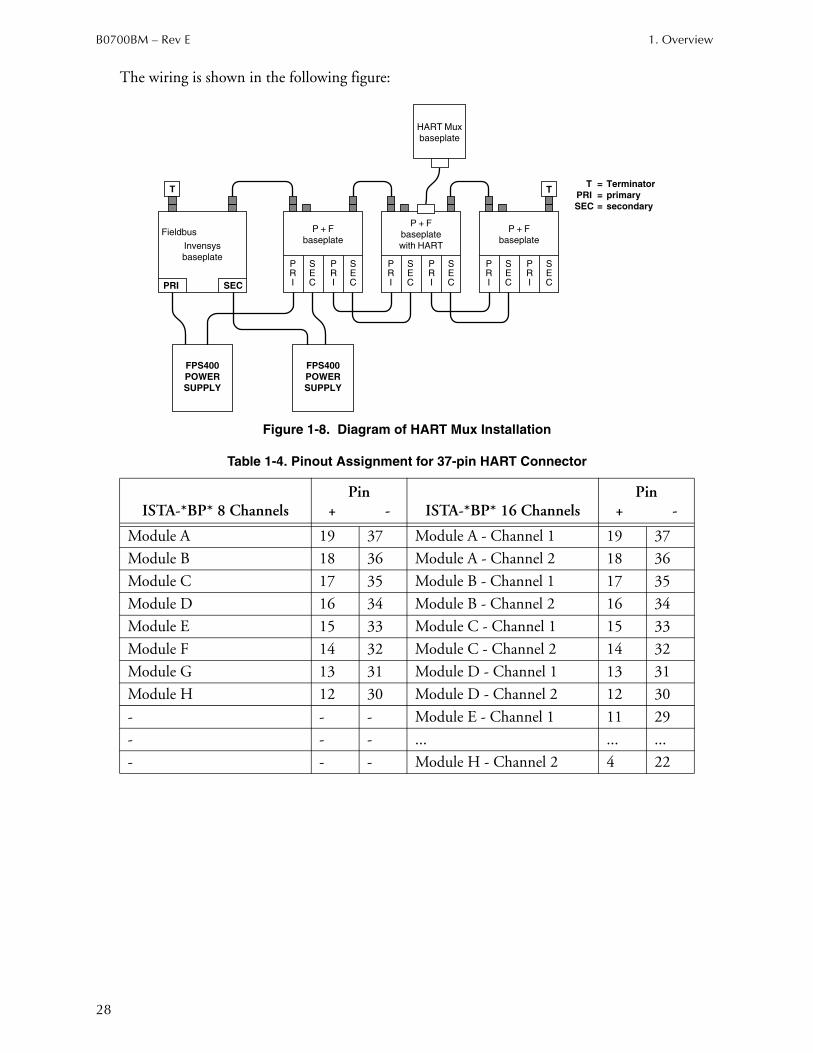
The wiring is shown in the following figure:
Figure 1-8. Diagram of HART Mux Installation
Table 1-4. Pinout Assignment for 37-pin HART Connector
ISTA-*BP* 8 ChannelsPin
+ - ISTA-*BP* 16 ChannelsPin
+ -
Module A 19 37 Module A - Channel 1 19 37
Module B 18 36 Module A - Channel 2 18 36
Module C 17 35 Module B - Channel 1 17 35
Module D 16 34 Module B - Channel 2 16 34
Module E 15 33 Module C - Channel 1 15 33
Module F 14 32 Module C - Channel 2 14 32
Module G 13 31 Module D - Channel 1 13 31
Module H 12 30 Module D - Channel 2 12 30
- - - Module E - Channel 1 11 29
- - - ... ... ...
- - - Module H - Channel 2 4 22
PRI SEC
TT
PRI
SEC
PRI
SEC
PRI
SEC
PRI
SEC
PRI
SEC
PRI
SEC
Invensys
baseplate
P + F
baseplate
P + F
baseplate
with HART
P + F
baseplate
FPS400
POWER
SUPPLY
FPS400
POWER
SUPPLY
T = Terminator
PRI = primary
SEC = secondary
Fieldbus
HART Mux
baseplate

1. Overview B0700BM – Rev E
29
Description of ISTA-*BP*s
Non-Redundant (Single)
Figure 1-9. ISTA-2XXy-BPYY Non-Redundant Baseplate
The following subsections describe the functions of the individual types of ISTA-*BP*s. For more detailed information concerning intrinsically safe isolator modules of series H-System, you can refer to the user's manual of Pepperl+Fuchs. The Invensys Foxboro Product Specification Sheets (PPSs) provide detailed Information on Fieldbus Modules (FBM).
NOTE
The wiring between the FBM and the H-System Modules is built into thebaseplate and ensures correct data exchange between the FBM and the eight H-System Modules.
ISTA-201-BPAI – 4 to 20 mA Input Interface Board, HART-CompatibleISTA-201-BPAI is fitted with eight 1-channel HiD2025 modules and prepared for mounting a FBM201 module. The HiD2025 provides a fully floating supply to power a 2-wire transmitter in a hazardous area. It repeats the measurement current in the safe area. The output is galvanically isolated from the input and referenced to the power supply return (commom). Bi-directional communication with a HART transmitter is possible via the 37-pin HART Connector.

B0700BM – Rev E 1. Overview
30
ISTA-201-BPAI-FD - 4 to 20 mA Input Interface Board, HART-Compatible, Line Fault DetectionISTA-201-BPAI-FD is fitted with eight 1-channel HiD2029 modules and prepared for mounting a FBM201 module. The HiD2029 provides a fully floating supply to power a 2- or 3-wire transmitter in a hazardous area, repeating the current to the FBM201. Bi-directional communication with a HART transmitter is possible via the 37-pin HART Connector.
The output is isolated from the input and the power supply. A separate fault output indicates if the input signal is outside the range 0.2 to 24 mA.
ISTA-201-BPTI - RTD/Thermocouple/mV Interface BoardISTA-201-BPTI is fitted with eight 2-channel HiD2082 modules and prepared for mounting a FBM201 module. The HiD2082 converter converts input signal of resistance temperature measurement sensors (RTD), several thermocouples or remote transducers from the hazardous area into an isolated analog current signal of 4 to 20 mA. The 4 to 20 mA signal is the input signal of the FBM201.
Supported RTD’s are Pt100 and Ni100 in 2-, 3- or 4-wire technology. Supported thermocouples are types B, E, J, K, L, N, R, S and T. The parameterization occurs via software (for example, PACTwareTM).
The output is isolated from the input and the power supply.
The FBM201 processes only data from the first channel of the HiD2082 module.
ISTA-204-BPAIO - 4 to 20 mA I/0 Interface Board, HART-CompatibleISTA-204-BPAIO is fitted with four 1-channel HiD2025 modules and four 1-channel HiD2031 modules. It is prepared for mounting a FBM204 module.
Mounting Station A to D:
The HiD2025 provides a fully floating supply to power a 2-wire transmitter in a hazardous area. It repeats the measurement current in the safe area. The output is galvanically isolated from the input and is referenced to the power supply return (common). Bi-directional communication with a HART transmitter is possible via the 37-pin HART Connector.
Mounting Station E to H:
The HiD2031 output repeater repeats a 4 to 20 mA input signal from the FBM204 to an I/P converter, control valve or display that is located in the hazardous area. The HiD2031 has a low input impedance. An open circuit in the field presents a high impedance to the FBM204 to allow alarm conditions to be monitored.
1. Overview B0700BM – Rev E
31
ISTA-204-BPAIO-FD - 4 to 20 mA I/0 Interface Board, Line Fault Detection, HART-CompatibleISTA-204-BPAIO-FD is fitted with four 1-channel HiD2025 modules and four 1-channel HiD2037 modules. It is prepared for mounting a FBM204 module.
Mounting Station A to D:
The HiD2025 provides a fully floating supply to power a 2-wire transmitter in a hazardous area. It repeats the measurement current in the safe area. The output is galvanically isolated from the input and is referenced to the power supply return (common).
Mounting Station E to H:
The HiD2037 repeats a 4 to 20 mA input signal from the FBM204 module to drive I/P converters, electro valve actuators and displays located in a hazardous area. HiD2037 was developed especially for use with the HART compatible field devices. A fault output reports a broken wire or short circuit via the fault output.
Bi-directional communication with HART transmitters or HART-Compatible actuators is possible via the 37-pin HART Connector.
ISTA-204-BPTIO - RTD/Thermocouple/mV Input, 4 to 20 mA Output Interface BoardISTA-204-BPTIO is fitted with four 1-channel HiD2031 modules and four 2-channel HiD2082 modules and prepared for mounting a FBM204 module.
Mounting Station A to D:
The HiD2082 converter converts input signals of resistance temperature measurement sensors (RTD), several thermocouples or remote transducers from the hazardous area into an isolated analog current signal of 4 to 20 mA. The 4 to 20 mA signal is the input signal of the FBM204.
Supported RTD’s are Pt100 and Ni100 in 2-, 3- or 4-wire technology. Supported thermocouples are types B, E, J, K, L, N, R, S and T. The parameterization occurs via software (for example, PACTwareTM). The output is isolated from the input and the power supply. The FBM204 processes only data from the first channel of the HiD2082 module.
Mounting Station E to H:
The HiD2031 output repeater repeats a 4 to 20 mA input signal from the FBM204 module to an I/P converter, control valve or display that is located in the hazardous area. The HiD2031 has a low input impedance. An open circuit in the field presents a high impedance to the FBM204 to allow alarm conditions to be monitored.
B0700BM – Rev E 1. Overview
32
ISTA-204-BPTIO-FD RTD/thermocouple/mV Input, 4 to 20 mA Output Interface Board, HART-Compatible, Line Fault DetectionISTA-204-BPTIO-FD is fitted with four 1-channel HiD2037 modules and four 2-channel HiD2082 modules. It is prepared for mounting a FBM204 module.
Mounting Station A to D:
The HiD2082 converter converts input signals of resistance temperature measurement sensors (RTD), several thermocouples or remote transducers from the hazardous area into an isolated analog current signal of 4 to 20 mA. The 4 to 20 mA signal is the input signal of the FBM204.
Supported RTD’s are Pt100 and Ni100 in 2-, 3- or 4-wire technology. Supported thermocouples are types B, E, J, K, L, N, R, S and T. The parameterization occurs via software (for example, PACTwareTM).
The output is isolated from the input and the power supply. The FBM204 processes only data from the first channel of the HiD2082 module.
Mounting Station E to H:
The HiD2037 repeats a 4 to 20 mA input signal from the FBM204 module to drive I/P converters, electro valve actuators and displays located in a hazardous area. HiD2037 was developed especially for use with the HART compatible field devices. A fault output reports a broken wire or short circuit via the fault output.
Bi-directional communication with HART compatible actuators is possible via the 37-pin HART Connector.
ISTA-207b-BPDI-FD - Voltage Monitor/Contact Sense Input Interface BoardISTA-207b-BPDI-FD is fitted with eight 2-channel HiD2822 modules. HiD2822 records the status of a voltage-free contact or proximity sensor in the hazardous area and reports the status via a relay output to the FBM207b module. Line fault monitoring turns off the output relay and sends an alarm indicating broken line or short circuit via an LED and fault output.
ISTA-211-BPAI - 4 to 20 mA Input Interface Board, HART-CompatibleISTA-211-BPAI is fitted with eight 2-channel HiD2026 modules and prepared for mounting a FBM211 module. The HiD2026 provides a fully floating supply to power two 2-wire transmitters in a hazardous area. It repeats the measurement current in the safe area. The outputs are galvanically isolated from the inputs and are referenced to the power supply return (common). Bi-directional communication with HART compatible actuators is possible via the 37-pin HART Connector.
ISTA-211-BPAI-3W - 4 to 20 mA Input Interface Board, HART-CompatibleISTA-211-BPAI-3W is fitted with eight 2-channel HiD2030 modules. The HiD2030 provides a fully floating supply to power two 2- or 3-wire transmitter in a hazardous area, repeating the current to the FBM211. Bi-directional communication with HART transmitters is possible via the 37-pin HART Connector.
The output are isolated from the inputs and the power supply. The different outputs are separated from each other. A separate fault output indicates if an input signal is outside the range 0.2 to 24 mA.
1. Overview B0700BM – Rev E
33
ISTA-211-BPTI - RTD/Thermocouple/mV Input Interface BoardISTA-211-BPTI is fitted with eight 2-channel HiD2082 modules and prepared for mounting a FBM211 module. The HiD2082 converter converts input signals of resistance temperature measurement sensors (RTD), several thermocouples or remote transducers from the hazardous area into an isolated analog current signal of 4 to 20 mA. The 4 to 20 mA signal is the input signal of the FBM211.
Supported RTD’s are Pt100 and Ni100 in 2-, 3- or 4-wire technology. Supported thermocouples are types B, E, J, K, L, N, R, S and T. The parameterization occurs via software (for example, PACTwareTM). The output are isolated from the inputs and the power supply.
ISTA-214-BPHI - HART-Communication, 4 to 20 mA Input Interface Board ISTA-214-BPHI is fitted with eight 1-channel HiD2025 modules and prepared for mounting a FBM214 module. The HiD2025 provides a fully floating supply to power a 2-wire transmitter in a hazardous area. It repeats the measurement current in the safe area. The output is galvanically isolated from the input and referenced to the power supply return (common).
ISTA-214-BPHI-FD - HART-Communication, 4 to 20 mA Input Interface Board, Line Fault DetectionISTA-214-BPHI-FD is fitted eight 1-channel HiD2029 modules and prepared for mounting a FBM214 module. The HiD2029 provides a fully floating supply to power a two or three wire transmitter in a hazardous area, repeating the current to the FBM214.
The output is isolated from the input and the power supply, and different outputs are separated from each other. A separate fault output indicates if the input signal is outside the range 0.2 to 24 mA.
ISTA-215-BPHO-FD - HART Communication 4 to 20 mA Output Interface Board, Line Fault DetectionISTA-215-BPHO-FD is fitted with eight 1-channel HiD2037 modules and prepared for mounting a FBM215 module. The HiD2037 repeats a 4 to 20 mA input signal from the FBM215 module to drive I/P converters, electro valve actuators and displays located in a hazardous area. HiD2037 was developed especially for use with the HART compatible field devices. A fault output reports a broken wire or short circuit via the fault output.
ISTA-217-BPDI-FD - Discrete Input Interface Board, Line Fault DetectionISTA-217-BPDI-FD is fitted with eight 4-channel HiD2844 modules and prepared for mounting a FBM217 module. HiD2844 records the status of a voltage-free connection or proximity sensor in the hazardous area and reports the status via an open collector output to the FBM217 module. Line fault monitoring turns off the output relay and sends an alarm indicating broken line or short circuit via an LED and fault output.
B0700BM – Rev E 1. Overview
34
ISTA-237-BPAO - 4 to 20 mA Output Interface BoardISTA-237-BPAO is fitted with eight 1-channel HiD2031 modules and prepared for mounting a FBM237 module. The HiD2031 output repeater repeats a 4 to 20 mA input signal from the FBM237 module to drive an I/P converter, control valve or display that is located in the hazardous area. The HiD2031 has a low input impedance. An open circuit in the field presents a high impedance to the FBM237 to allow alarm conditions to be monitored.
ISTA-237-BPAO-FD - 4 to 20 mA Output Interface Board, HART-Compatible, Line Fault DetectionISTA-237-BPAO-FD is fitted with eight 1-channel HiD2037 modules and prepared for mounting a FBM237 module. The HiD2037 output repeater repeats a 4 to 20 mA input signal from the FBM237 module to an I/P converter, control valve or display that is located in the hazardous area. HiD2037 was developed especially for use with the HART compatible actuators. Bi-directional communication is possible via the 37-pin HART Connector.
A fault output reports a broken wire or short circuit on the field side.
ISTA-241c-BPDIO - Discrete I/O Interface Board ISTA-241c-BPDIO is fitted with four 2-channel HiD2822 modules and four 2-channel HiD2872 modules and prepared for mounting a FBM241c module.
Mounting station A to D:
HiD2822 records the status of a voltage-free connection or proximity sensor in the hazardous area and reports the status via a relay output to the FBM241c module. Line fault monitoring turns off the output relay and sends an alarm indicating broken line or short circuit via an LED and fault output.
Mounting station E to H:
HiD2872 switches intrinsically safe solenoid valves, alarms, displays or LED displays in the hazardous area and is controlled by the outputs of the FBM241c module.
ISTA-241c-BPDIO-FD - Discrete I/O Interface Board, Line Fault DetectionISTA-241c-BPDIO-FD is fitted with four 2-channel HiD2822 modules and four 2-channel HiD2872 modules and prepared for mounting a FBM241c module.
Mounting Station A to D:
HiD2822 records the status of a voltage-free connection or proximity sensor in the hazardous area and reports the status via a relay output to the FBM241c module. Line fault monitoring turns off the output relay and sends an alarm indicating broken line or short circuit via an LED and fault output.
Mounting Station E to H:
HiD2872 switches intrinsically safe solenoid valves, alarms, displays or LED displays in the hazardous area and is controlled by the outputs of the FBM241c module. A fault output reports a broken wire or short circuit.
1. Overview B0700BM – Rev E
35
ISTA-242-BPDO - Externally Sourced Discrete Output Interface BoardISTA-242-BPDO is fitted with eight 2-channel HiD2876 modules and prepared for mounting a FBM242 module. HiD2876 switches intrinsically safe solenoid valves, alarms, displays or LED displays in the hazardous area and is controlled by a binary signal from the FBM242 module.
ISTA-242-BPDO-FD - Externally Sourced Discrete Output Interface Board, Line Fault DetectionISTA-242-BPDO-FD is fitted with eight 2-channel HiD2872 modules and prepared for mounting a FBM242 module. HiD2872 switches intrinsically safe solenoid valves, alarms, displays or LED displays in the hazardous area and is controlled by a binary signal from the FBM 242 module. The fault output reports a broken wire or short circuit.
B0700BM – Rev E 1. Overview
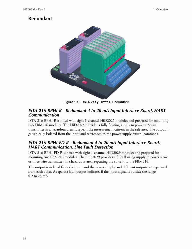
36
Redundant
Figure 1-10. ISTA-2XXy-BPYY-R Redundant
ISTA-216-BPHI-R - Redundant 4 to 20 mA Input Interface Board, HART CommunicationISTA-216-BPHI-R is fitted with eight 1-channel HiD2025 modules and prepared for mounting two FBM216 modules. The HiD2025 provides a fully floating supply to power a 2-wire transmitter in a hazardous area. It repeats the measurement current in the safe area. The output is galvanically isolated from the input and referenced to the power supply return (common).
ISTA-216-BPHI-FD-R - Redundant 4 to 20 mA Input Interface Board, HART Communication, Line Fault DetectionISTA-216-BPHI-FD-R is fitted with eight 1-channel HiD2029 modules and prepared for mounting two FBM216 modules. The HiD2029 provides a fully floating supply to power a two or three wire transmitter in a hazardous area, repeating the current to the FBM216.
The output is isolated from the input and the power supply, and different outputs are separated from each other. A separate fault output indicates if the input signal is outside the range 0.2 to 24 mA.
1. Overview B0700BM – Rev E
37
ISTA-218-BPHO-FD-R - Redundant 4 to 20 mA Output Interface, HART Communication, Board, Line Fault DetectionISTA-218-BPHO-FD-R is fitted with eight 1-channel HiD2037 modules and prepared for mounting two FBM218 modules. The HiD2037 repeats a 4 to 20 mA input signal from the FBM218 modules to drive I/P converters, electro valve actuators and displays located in a hazardous area. HiD2037 was developed especially for use with the HART compatible field devices. A fault output reports a broken wire or short circuit via the fault output.
ISTA-237-BPAO-R - Redundant 4 to 20 mA Output Interface BoardISTA-237-BPAO-R is fitted with eight 1-channel HiD2031 modules and prepared for mounting two FBM237 modules. The HiD2031 output repeater repeats a 4 to 20 mA input signal from the FBM237 modules to an I/P converter, control valve or display that is located in a hazardous area. The HiD2031 has a low input impedance. An open circuit in the field presents a high impedance to the FBM237 to allow alarm conditions to be monitored.
ISTA-237-BPAO-FD-R - Redundant 4 to 20 mA Output Interface Board, Line Fault Detection, HART-CompatibleISTA-237-BPAO-FD is fitted with eight 1-channel HiD2037 modules and prepared for mounting two FBM237 modules. The HiD2037 repeats a 4 to 20 mA input signal from the FBM237 module to drive I/P converters, electro valve actuators and displays located in a hazardous area. HiD2037 was developed especially for use with the HART compatible field devices. A fault output reports a broken wire or short circuit via the fault output.
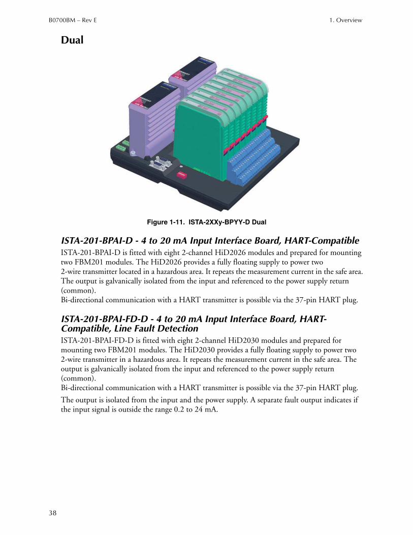
B0700BM – Rev E 1. Overview
38
Dual
Figure 1-11. ISTA-2XXy-BPYY-D Dual
ISTA-201-BPAI-D - 4 to 20 mA Input Interface Board, HART-CompatibleISTA-201-BPAI-D is fitted with eight 2-channel HiD2026 modules and prepared for mounting two FBM201 modules. The HiD2026 provides a fully floating supply to power two 2-wire transmitter located in a hazardous area. It repeats the measurement current in the safe area. The output is galvanically isolated from the input and referenced to the power supply return (common). Bi-directional communication with a HART transmitter is possible via the 37-pin HART plug.
ISTA-201-BPAI-FD-D - 4 to 20 mA Input Interface Board, HART-Compatible, Line Fault DetectionISTA-201-BPAI-FD-D is fitted with eight 2-channel HiD2030 modules and prepared for mounting two FBM201 modules. The HiD2030 provides a fully floating supply to power two 2-wire transmitter in a hazardous area. It repeats the measurement current in the safe area. The output is galvanically isolated from the input and referenced to the power supply return (common). Bi-directional communication with a HART transmitter is possible via the 37-pin HART plug.
The output is isolated from the input and the power supply. A separate fault output indicates if the input signal is outside the range 0.2 to 24 mA.
1. Overview B0700BM – Rev E
39
ISTA-201-BPTI-D - RTD/Thermocouple/mV Interface BoardISTA-201-BPTI-D is fitted with eight 2-channel HiD2082 modules and prepared for mounting two FBM201 modules. The HiD2082 is a 2-channel converter to convert input signals of resistance temperature measurement sensors (RTDs), several thermocouples or remote transducers from the hazardous area into an isolated analog current signal of 4 to 20 mA. The 4 to 20 mA signal is the input signal of the FBM201.
Supported RTD's are Pt100 and Ni100 in 2-, 3-, or 4-wire technology. Supported thermocouples are types B, E, J, K, L, N, R, S and T. The parameterization occurs via software (for example, PACTwareTM). The output is isolated from the input and the power supply.
ISTA-204-BPAIO-D - 4 to 20 mA I/O Interface Board, HART-CompatibleISTA-204-BPAIO-D is fitted with four 2-channel HiD2026 modules and four 2-channel HiD2032 modules. It is prepared for mounting two FBM204 modules.
Mounting Station A, B and E, F:
The HiD2026 provides a fully floating supply to power two 2-wire transmitters in a hazardous area. It repeats the measurement current in the safe area. The output is galvanically isolated from the input and referenced to the power supply return (common). Bi-directional communication with a HART transmitter is possible via the 37-pin HART plug.
Mounting Station C, D and G, H:
The HiD2032 is a 2-channel output repeater and repeats a 4 to 20 mA input signal from a control system to an I/P converter, control valve or display that is located in the hazardous area. The HiD2032 has a low input impedance. An open circuit in the field presents a high impedance to the FBM204 to allow alarm conditions to be monitored.
ISTA-204-BPAIO-FD-D - 4 to 20 mA I/O Interface Board, HART-Compatible, Line Fault DetectionISTA-204-BPAIO-FD-D is fitted with four 2-channel HiD2026 modules and four 2-channel HiD2038 modules. It is prepared for mounting two FBM204 modules.
Mounting Station A, B and E, F:
The HiD2026 provides a fully floating supply to power two 2-wire transmitter in a hazardous area. It repeats the measurement current in the safe area. The output is galvanically isolated from the input and referenced to the power supply return (common).
Mounting Station C, D and G, H:
The HiD2038 is a 2-channel output repeater and repeats a 4 to 20 mA input signal from the FBM204 module to drive I/P converters, electro valve actuators and displays located in a hazardous area. The HiD2038 was developed especially for the use with the HART compatible field devices. A fault output reports a lead breakage or short circuit via the fault output.
Bi-directional communication with HART transmitters or HART compatible actuators is possible via the 37-pin HART plug.
B0700BM – Rev E 1. Overview
40
ISTA-204-BPTIO-D - RTD/Thermocouple/mV Input, 4 to 20 mA Output Interface BoardISTA-204-BPTIO-D is fitted with four 2-channel HiD2032 modules and four 2-channel HiD2082 modules. It is prepared for mounting two FBM204 modules.
Mounting Station A, B and E, F:
The HiD2082 is a 2-channel converter to convert input signals of resistance temperature measurement sensors (RTDs), several thermocouples or remote transducers from the hazardous area into an isolated analog current signal of 4 to 20 mA. The 4 to 20 mA signal is the input signal of the FBM204.
Supported RTD's are Pt100 and Ni100 in 2-, 3-, or 4-wire technology. Supported thermocouples are types B, E, J, K, L, N, R, S and T. The parameterization occurs via software (for example, PACTwareTM).
The output is isolated from the input and the power supply.
Mounting Station C, D and G, H:
The HiD2032 is a 2-channel output repeater and repeats a 4 to 20 mA input signal from a control system to an I/P converter, control valve or display that is located in the hazardous area. The HiD2032 has a low input impedance. An open circuit in the field presents a high impedance to the FBM204 to allow alarm conditions to be monitored.
ISTA-204-BPTIO-FD-D - RTD/Thermocouple/mV Input, 4 to 20 mA Output Interface Board, HART-Compatible, Line Fault DetectionISTA-204-BPTIO-FD-D is fitted with four 2-channel HiD2038 modules and four 2-channel HiD2082 modules. It is prepared for mounting two FBM204 modules.
Mounting Station A, B and E, F:
The HiD2082 is a 2-channel converter to convert input signals of resistance temperature measurement sensors (RTDs), several thermocouples or remote transducers from the hazardous area into an isolated analog current signal of 4 to 20 mA. The 4 to 20 mA signal is the input signal of the FBM204.
Supported RTD's are Pt100 and Ni100 in 2-, 3-, or 4-wire technology. Supported thermocouples are types B, E, J, K, L, N, R, S and T. The parameterization occurs via software (for example, PACTwareTM).
The output is isolated from the input and the power supply.
Mounting Station C, D and G, H:
The HiD2038 is a 2-channel output repeater and repeats a 4 to 20 mA input signal from the FBM204 module to drive I/P converters, electro valve actuators and displays located in a hazardous area. The HiD2038 was developed especially for the use with the HART compatible field devices. A fault output reports a broken wire or short circuit via the fault output. Bi-directional communication with HART transmitters or HART compatible actuators is possible via the 37-pin HART plug.
1. Overview B0700BM – Rev E
41
ISTA-214-BPHI-D - HART-Communication, 4 to 20 mA Input Interface BoardISTA-214-BPHI-D is fitted with eight 2-channel HiD2026 modules and prepared for mounting two FBM214 modules. The HiD2026 provides a fully floating supply to power two 2-wire transmitter in a hazardous area. It repeats the measurement current in the safe area. The outputs are galvanically isolated from the inputs and referenced to the power supply return (common).
ISTA-214-BPHI-FD-D - HART-Communication, 4 to 20 mA Input Interface Board, Line Fault DetectionISTA-214-BPHI-D is fitted with eight 2-channel HiD2030 modules and prepared for mounting two FBM214 modules. The HiD2030 provides a fully floating supply to power two 2-wire transmitter in a hazardous area. It repeats the measurement current in the safe area. The outputs are galvanically isolated from the inputs and referenced to the power supply return (common). A fault output reports a broken wire or short circuit via the fault output.
ISTA-215-BPHO-FD-D - HART-Communication, 4 to 20 mA Output Interface Board, Line Fault Detection ISTA-215-BPHO-FD-D is fitted with eight 2-channel HiD2038 modules and prepared for mounting two FBM215 modules. The HiD2038 repeats a 4 to 20 mA input signal from the FBM215 module to drive I/P converters, electro valve actuators and displays located in a hazardous area. HiD2038 was developed especially for use with the HART compatible field devices. A fault output reports a broken wire or short circuit via the fault output.

B0700BM – Rev E 1. Overview
42
43
2. Enclosure Installation
This chapter consists of installation information for the ISTA-*BP* enclosures.
I/O CabinetThe following points should be noted when selecting and setting up the I/O cabinet.
CAUTION!
Read “Safety Consideration” on page 2 and the safety instructions of the I/O cabinet manufacturer and observe them during planning, installation and setting up.
The protection class of ISTA-*BP* corresponds to IP 20 in accordance with IEC/EN 60529. In the case of adverse ambient conditions, it must be installed appropriately in a Cabinet with a higher protection class.
CAUTION!
If the installation is performed in Division2/Zone 2 hazardous area, Cabinets with a protection class of IP 54 or higher in accordance with IEC/EN 60529 must be used.
NOTE
A high installation density of ISTA-*BP*s, two position baseplates and power supplies requires forced air ventilation in the cabinet. The necessary protection class of the cabinet must be taken into consideration in designing the ventilation!
For more detailed information related to determining heat dissipation and the design of forced air ventilation, please refer to the user's manual Series H-System - Intrinsic Safety Isolators (www.pepperl-fuchs.com) and DIN Rail Mounted Subsystem User’s Guide (B0400FA).
Installation of the ISTA-*BP*s enclosures involves mounting the enclosure on the floor or on a wall at the desired location, and making the required power and earthing (grounding) connections.

B0700BM – Rev E 2. Enclosure Installation
44
WARNING!
To prevent the hazard of electrical shock and signal interference, high voltage main power cables (those carrying 30 V rms or greater, or 60 V dc or greater) must be kept separate from low voltage signal cables (those carrying less than 30 V rms, or less than 60 V dc). Separate conduit, cable runs, and so forth, must be used, as well as separate cable entries into the enclosure. The minimum allowable separation between high and low voltage cables is 50 mm (2 in) at all points in the cable run.Also IS and non-IS cables must be separated. Minimum distance between the cables is 50 mm (2 in).Also refer to B0700AU for Power, Earthing (Grounding), EMC and CE Compliance.
Figure 2-1. I/O Cabinet Layout
FCP-baseplate
for FCP, FCM etc.
Single version
Dual or redundant version
Fan
Power supply
FPS400
Cable duct
for IS-signals
Plinth
Cable duct
for Non IS-signals
800
10
02
00
0
2. Enclosure Installation B0700BM – Rev E
45
Preinstallation Procedures
The following procedures provide general information regarding unloading and unpacking of all ISTA-*BP* equipment, and performing checks on the power network to be used by the equipment.
UnloadingISTA-*BP*s are designed to withstand vibration and shock normally encountered during shipping and installation; however, extreme shocks and vibration should be avoided. If practical, all major movements of the units should be accomplished before the units are unpacked.
UnpackingThe following unpacking procedure applies, in general, to all ISTA-*BP* units:
1. Inspect the exterior of the shipping carton for obvious damage. (Any noticeable damage should be indicated in the shipper’s bill of lading.)
2. Verify that the equipment received is that described in the bill of lading.
3. Remove shipping straps, shipping shroud, and other packing materials, such as polyethylene bags and styrofoam cushioning materials.
NOTE
If you anticipate that the unit will be stored, or shipped from the present site, save all packing materials for reuse.
4. If the unit is attached to a skid, remove all shipping hardware and hold-down bolts used to fasten the unit to the skid. Separate the skid from the unit.
5. Ensure that the appropriate interconnecting cables are present, by comparing the cable part numbers and quantities with those listed in the bill of lading.
Subsystem Power ChecksPerform the following checks before installing the equipment:
1. Check that the required ac or dc power distribution network lines are installed.
2. Check that the appropriate number of ac power outlets (if required) are installed and spaced appropriately.
3. Switch on main system power and, using a multimeter, check that the appropriate operating voltage exists at each enclosure connection point before applying power to the equipment.

B0700BM – Rev E 2. Enclosure Installation
46
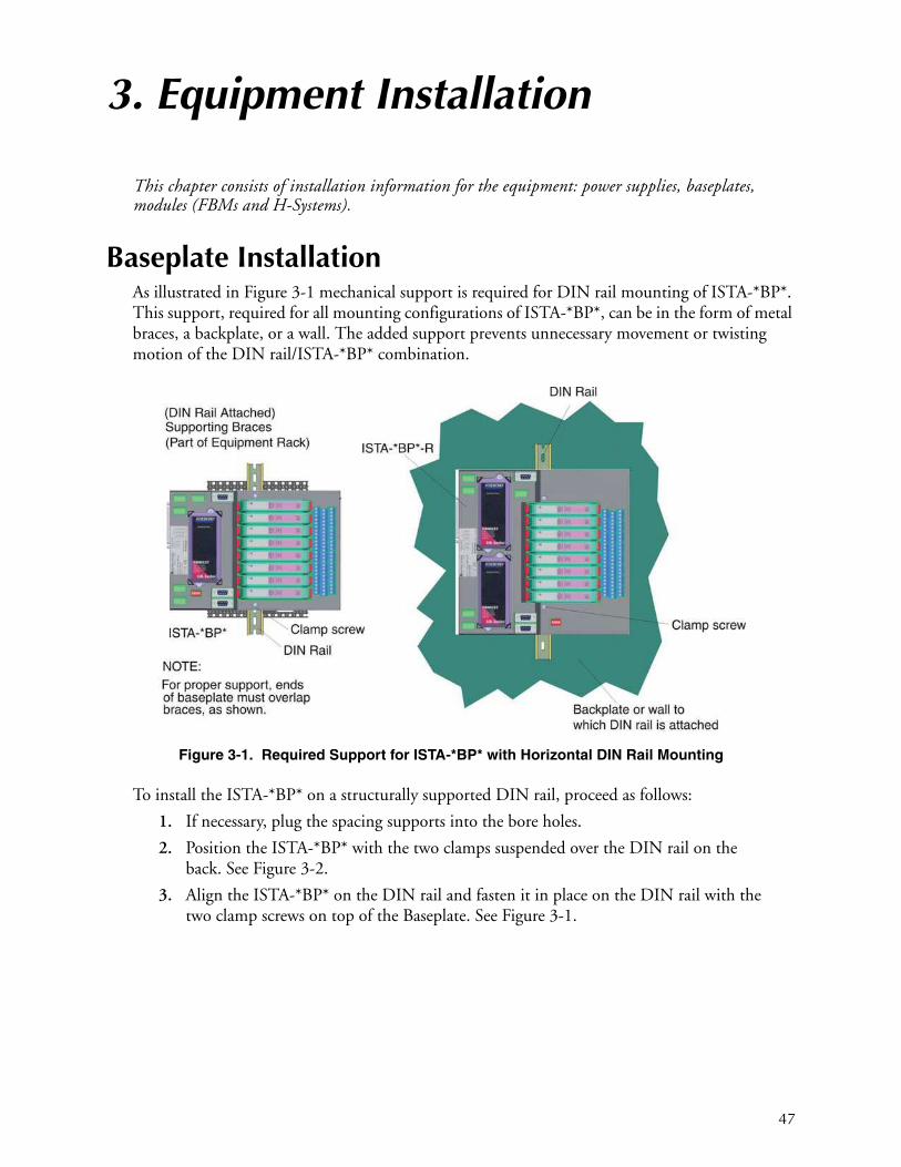
47
3. Equipment Installation
This chapter consists of installation information for the equipment: power supplies, baseplates, modules (FBMs and H-Systems).
Baseplate InstallationAs illustrated in Figure 3-1 mechanical support is required for DIN rail mounting of ISTA-*BP*. This support, required for all mounting configurations of ISTA-*BP*, can be in the form of metal braces, a backplate, or a wall. The added support prevents unnecessary movement or twisting motion of the DIN rail/ISTA-*BP* combination.
Figure 3-1. Required Support for ISTA-*BP* with Horizontal DIN Rail Mounting
To install the ISTA-*BP* on a structurally supported DIN rail, proceed as follows:
1. If necessary, plug the spacing supports into the bore holes.
2. Position the ISTA-*BP* with the two clamps suspended over the DIN rail on the back. See Figure 3-2.
3. Align the ISTA-*BP* on the DIN rail and fasten it in place on the DIN rail with the two clamp screws on top of the Baseplate. See Figure 3-1.
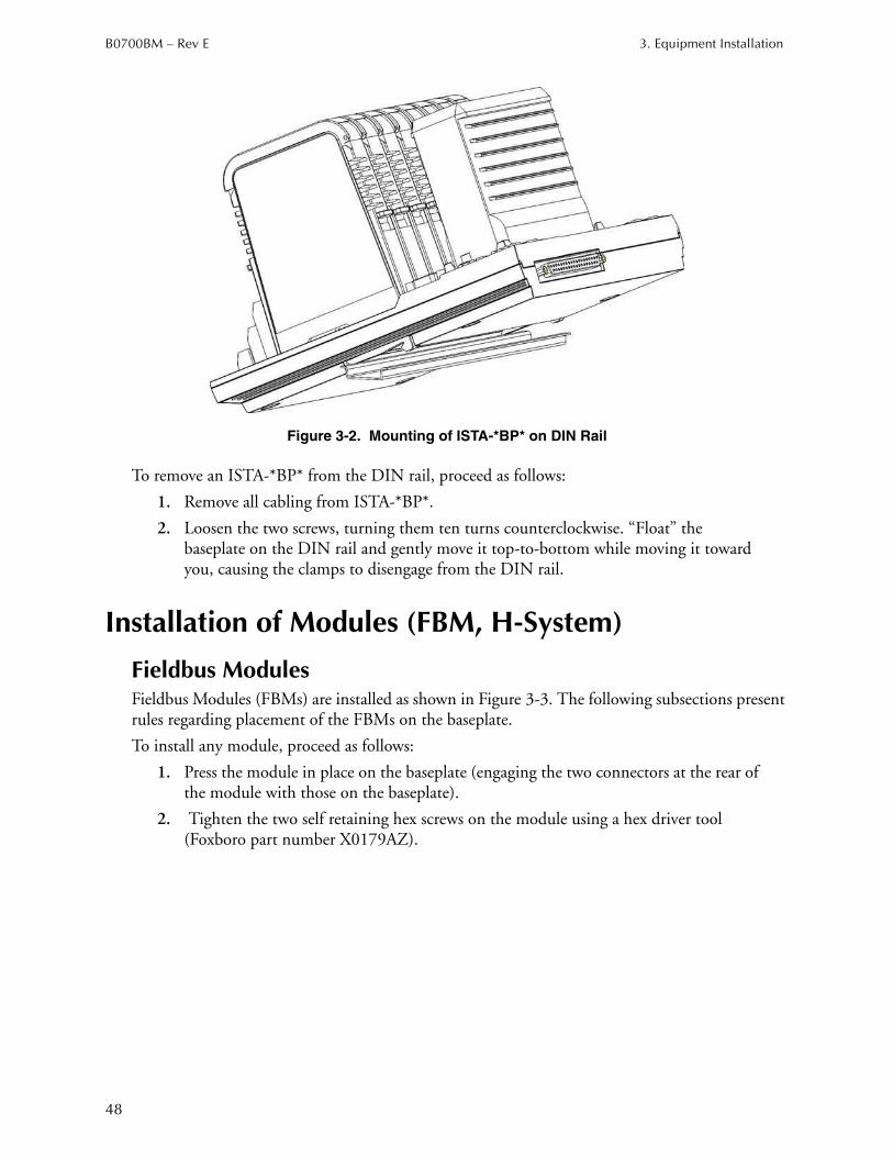
B0700BM – Rev E 3. Equipment Installation
48
Figure 3-2. Mounting of ISTA-*BP* on DIN Rail
To remove an ISTA-*BP* from the DIN rail, proceed as follows:
1. Remove all cabling from ISTA-*BP*.
2. Loosen the two screws, turning them ten turns counterclockwise. “Float” the baseplate on the DIN rail and gently move it top-to-bottom while moving it toward you, causing the clamps to disengage from the DIN rail.
Installation of Modules (FBM, H-System)
Fieldbus ModulesFieldbus Modules (FBMs) are installed as shown in Figure 3-3. The following subsections present rules regarding placement of the FBMs on the baseplate.
To install any module, proceed as follows:
1. Press the module in place on the baseplate (engaging the two connectors at the rear of the module with those on the baseplate).
2. Tighten the two self retaining hex screws on the module using a hex driver tool (Foxboro part number X0179AZ).
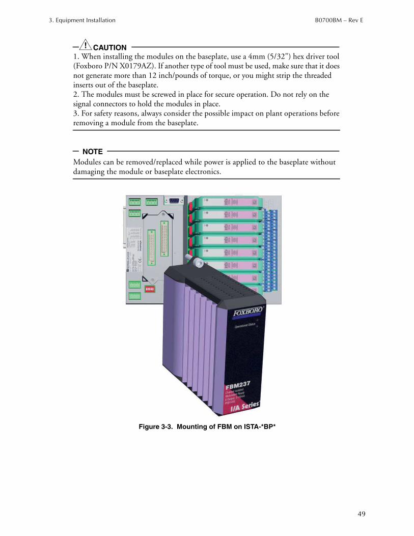
3. Equipment Installation B0700BM – Rev E
49
CAUTION!
1. When installing the modules on the baseplate, use a 4mm (5/32") hex driver tool (Foxboro P/N X0179AZ). If another type of tool must be used, make sure that it does not generate more than 12 inch/pounds of torque, or you might strip the threaded inserts out of the baseplate.2. The modules must be screwed in place for secure operation. Do not rely on the signal connectors to hold the modules in place.3. For safety reasons, always consider the possible impact on plant operations before removing a module from the baseplate.
NOTE
Modules can be removed/replaced while power is applied to the baseplate without damaging the module or baseplate electronics.
Figure 3-3. Mounting of FBM on ISTA-*BP*
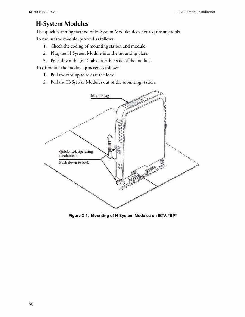
B0700BM – Rev E 3. Equipment Installation
50
H-System ModulesThe quick fastening method of H-System Modules does not require any tools.
To mount the module. proceed as follows:
1. Check the coding of mounting station and module.
2. Plug the H-System Module into the mounting plate.
3. Press down the (red) tabs on either side of the module.
To dismount the module, proceed as follows:
1. Pull the tabs up to release the lock.
2. Pull the H-System Modules out of the mounting station.
Figure 3-4. Mounting of H-System Modules on ISTA-*BP*
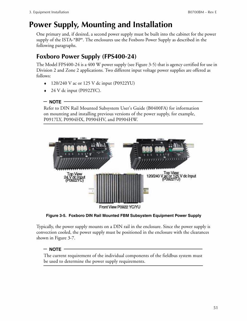
3. Equipment Installation B0700BM – Rev E
51
Power Supply, Mounting and Installation
One primary and, if desired, a second power supply must be built into the cabinet for the power supply of the ISTA-*BP*. The enclosures use the Foxboro Power Supply as described in the following paragraphs.
Foxboro Power Supply (FPS400-24)The Model FPS400-24 is a 400 W power supply (see Figure 3-5) that is agency certified for use in Division 2 and Zone 2 applications. Two different input voltage power supplies are offered as follows:
♦ 120/240 V ac or 125 V dc input (P0922YU)
♦ 24 V dc input (P0922YC).
NOTE
Refer to DIN Rail Mounted Subsystem User's Guide (B0400FA) for information on mounting and installing previous versions of the power supply, for example, P0917LY, P0904HX, P0904HV, and P0904HW.
Figure 3-5. Foxboro DIN Rail Mounted FBM Subsystem Equipment Power Supply
Typically, the power supply mounts on a DIN rail in the enclosure. Since the power supply is convection cooled, the power supply must be positioned in the enclosure with the clearances shown in Figure 3-7.
NOTE
The current requirement of the individual components of the fieldbus system must be used to determine the power supply requirements.
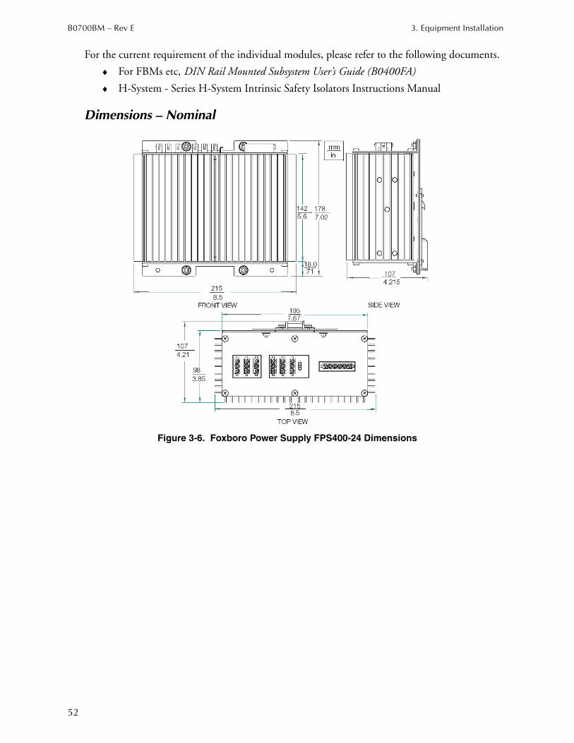
B0700BM – Rev E 3. Equipment Installation
52
For the current requirement of the individual modules, please refer to the following documents.
♦ For FBMs etc, DIN Rail Mounted Subsystem User’s Guide (B0400FA)
♦ H-System - Series H-System Intrinsic Safety Isolators Instructions Manual
Dimensions – Nominal
Figure 3-6. Foxboro Power Supply FPS400-24 Dimensions
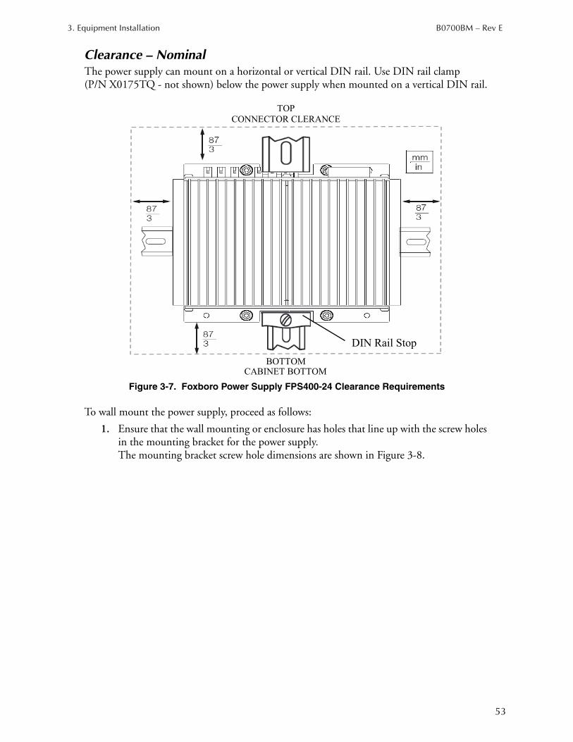
3. Equipment Installation B0700BM – Rev E
53
Clearance – NominalThe power supply can mount on a horizontal or vertical DIN rail. Use DIN rail clamp (P/N X0175TQ - not shown) below the power supply when mounted on a vertical DIN rail.
Figure 3-7. Foxboro Power Supply FPS400-24 Clearance Requirements
To wall mount the power supply, proceed as follows:
1. Ensure that the wall mounting or enclosure has holes that line up with the screw holes in the mounting bracket for the power supply. The mounting bracket screw hole dimensions are shown in Figure 3-8.
BOTTOM CABINET BOTTOM
TOP
CONNECTOR CLERANCE
DIN Rail Stop
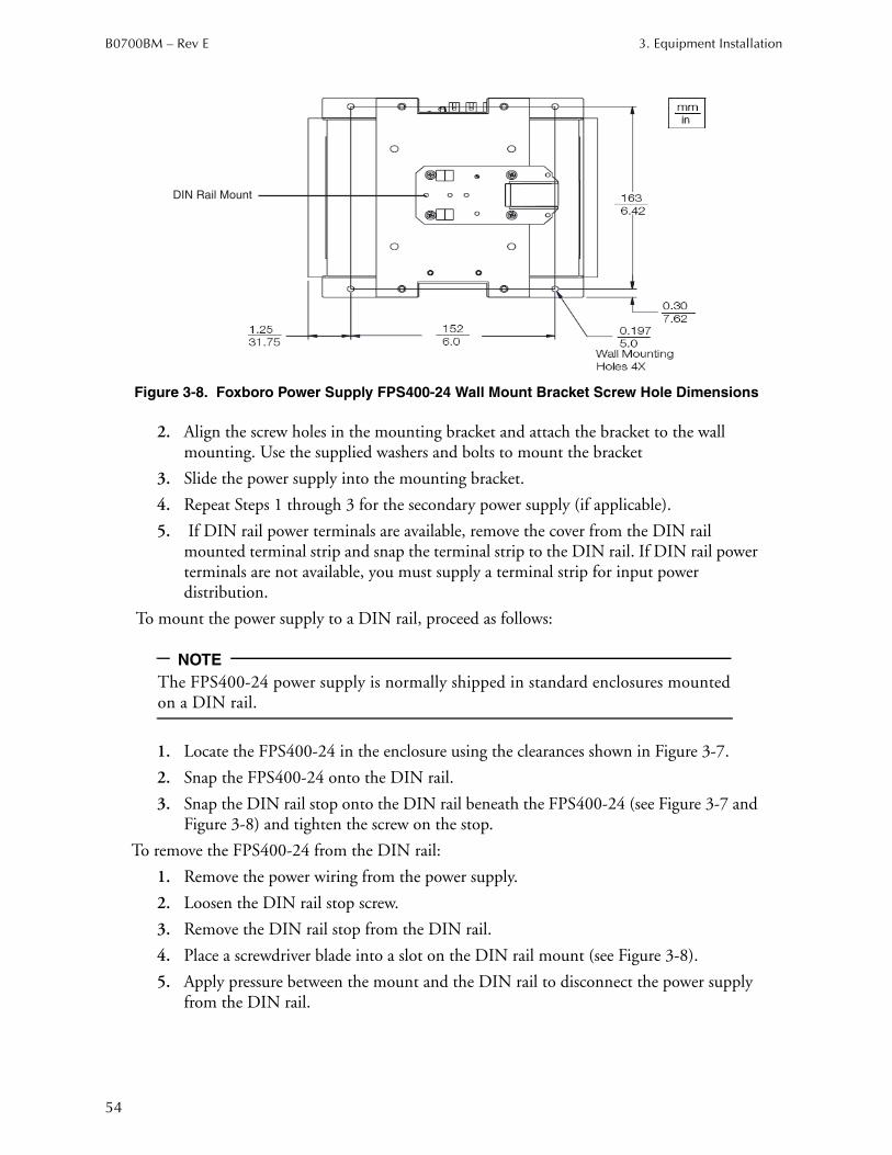
B0700BM – Rev E 3. Equipment Installation
54
Figure 3-8. Foxboro Power Supply FPS400-24 Wall Mount Bracket Screw Hole Dimensions
2. Align the screw holes in the mounting bracket and attach the bracket to the wall mounting. Use the supplied washers and bolts to mount the bracket
3. Slide the power supply into the mounting bracket.
4. Repeat Steps 1 through 3 for the secondary power supply (if applicable).
5. If DIN rail power terminals are available, remove the cover from the DIN rail mounted terminal strip and snap the terminal strip to the DIN rail. If DIN rail power terminals are not available, you must supply a terminal strip for input power distribution.
To mount the power supply to a DIN rail, proceed as follows:
NOTE
The FPS400-24 power supply is normally shipped in standard enclosures mounted on a DIN rail.
1. Locate the FPS400-24 in the enclosure using the clearances shown in Figure 3-7.
2. Snap the FPS400-24 onto the DIN rail.
3. Snap the DIN rail stop onto the DIN rail beneath the FPS400-24 (see Figure 3-7 and Figure 3-8) and tighten the screw on the stop.
To remove the FPS400-24 from the DIN rail:
1. Remove the power wiring from the power supply.
2. Loosen the DIN rail stop screw.
3. Remove the DIN rail stop from the DIN rail.
4. Place a screwdriver blade into a slot on the DIN rail mount (see Figure 3-8).
5. Apply pressure between the mount and the DIN rail to disconnect the power supply from the DIN rail.
DIN Rail Mount
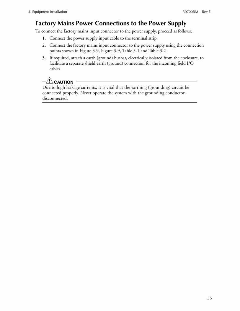
3. Equipment Installation B0700BM – Rev E
55
Factory Mains Power Connections to the Power SupplyTo connect the factory mains input connector to the power supply, proceed as follows:
1. Connect the power supply input cable to the terminal strip.
2. Connect the factory mains input connector to the power supply using the connection points shown in Figure 3-9, Figure 3-9, Table 3-1 and Table 3-2.
3. If required, attach a earth (ground) busbar, electrically isolated from the enclosure, to facilitate a separate shield earth (ground) connection for the incoming field I/O cables.
CAUTION!
Due to high leakage currents, it is vital that the earthing (grounding) circuit be connected properly. Never operate the system with the grounding conductor disconnected.
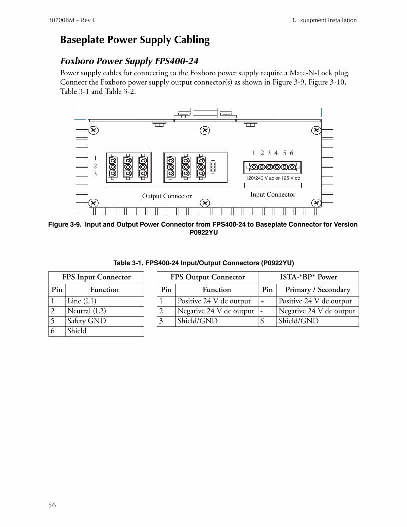
B0700BM – Rev E 3. Equipment Installation
56
Baseplate Power Supply Cabling
Foxboro Power Supply FPS400-24Power supply cables for connecting to the Foxboro power supply require a Mate-N-Lock plug. Connect the Foxboro power supply output connector(s) as shown in Figure 3-9, Figure 3-10, Table 3-1 and Table 3-2.
Figure 3-9. Input and Output Power Connector from FPS400-24 to Baseplate Connector for Version
P0922YU
Table 3-1. FPS400-24 Input/Output Connectors (P0922YU)
FPS Input Connector FPS Output Connector ISTA-*BP* Power
Pin Function Pin Function Pin Primary / Secondary
1 Line (L1) 1 Positive 24 V dc output + Positive 24 V dc output
2 Neutral (L2) 2 Negative 24 V dc output - Negative 24 V dc output
5 Safety GND 3 Shield/GND S Shield/GND
6 Shield
1
2
3
1 2 3 4 5 6
Output Connector Input Connector
120/240 V ac or 125 V dc
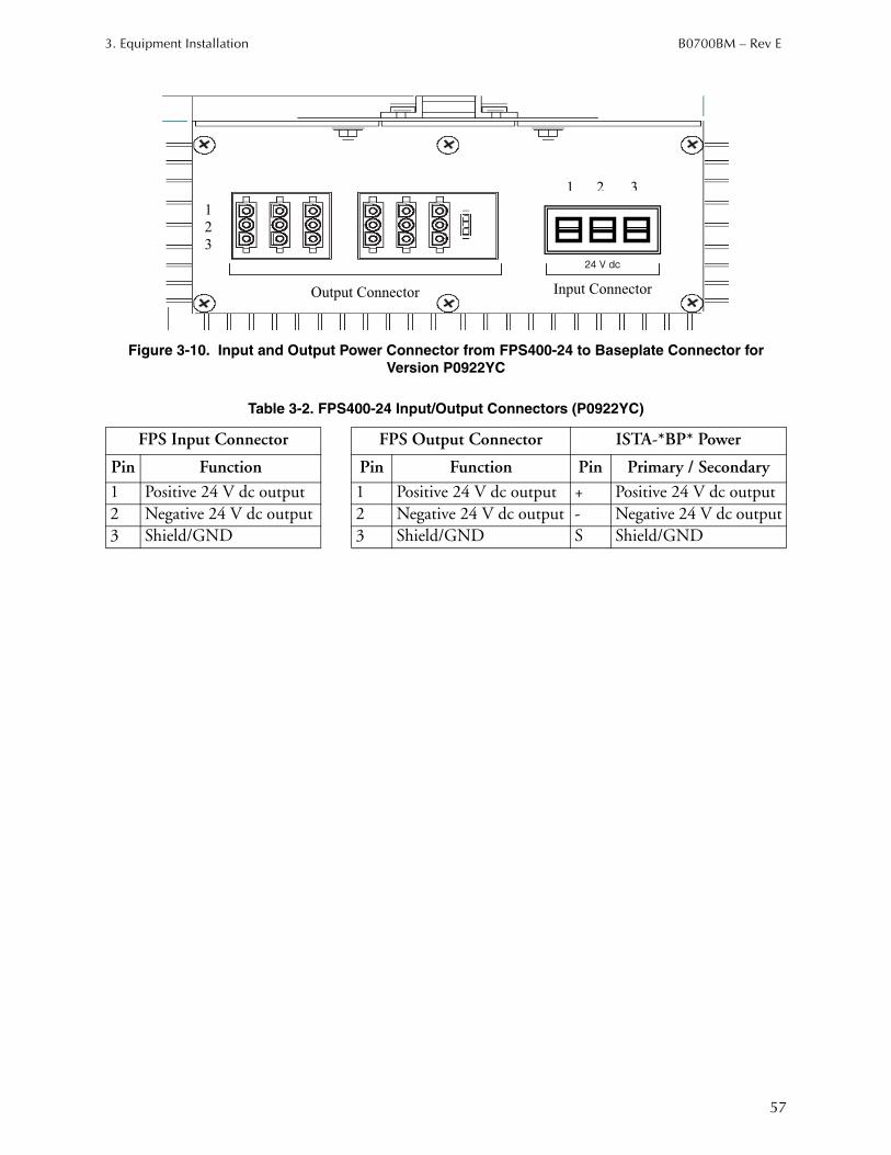
3. Equipment Installation B0700BM – Rev E
57
Figure 3-10. Input and Output Power Connector from FPS400-24 to Baseplate Connector for
Version P0922YC
Table 3-2. FPS400-24 Input/Output Connectors (P0922YC)
FPS Input Connector FPS Output Connector ISTA-*BP* Power
Pin Function Pin Function Pin Primary / Secondary
1 Positive 24 V dc output 1 Positive 24 V dc output + Positive 24 V dc output
2 Negative 24 V dc output 2 Negative 24 V dc output - Negative 24 V dc output
3 Shield/GND 3 Shield/GND S Shield/GND
1
2
3
1 2 3
Output Connector Input Connector
24 V dc
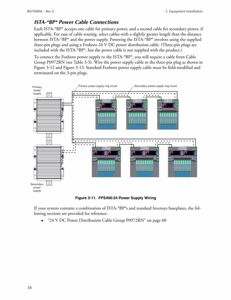
B0700BM – Rev E 3. Equipment Installation
58
ISTA-*BP* Power Cable ConnectionsEach ISTA-*BP* accepts one cable for primary power, and a second cable for secondary power, if applicable. For ease of cable routing, select cables with a slightly greater length than the distance between ISTA-*BP* and the power supply. Powering the ISTA-*BP* involves using the supplied three-pin plugs and using a Foxboro 24 V DC power distribution cable. (Three-pin plugs are included with the ISTA-*BP*, but the power cable is not supplied with the product.)
To connect the Foxboro power supply to the ISTA-*BP*, you will require a cable from Cable Group P0972RN (see Table 3-3). Wire the power supply cable to the three-pin plug as shown in Figure 3-12 and Figure 3-13. Standard Foxboro power supply cable must be field-modified and terminated on the 3-pin plugs.
Figure 3-11. FPS400-24 Power Supply Wiring
If your system contains a combination of ISTA-*BP*s and standard Invensys baseplates, the fol-lowing sections are provided for reference:
♦ “24 V DC Power Distribution Cable Group P0972RN” on page 60
Primary power supply ring circuitPrimary
power
supply
Secondary power supply ring circuit
Secondary
power
supply
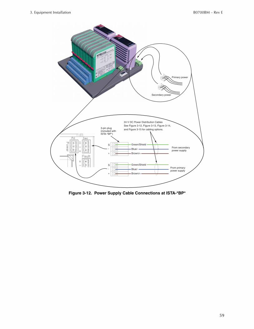
3. Equipment Installation B0700BM – Rev E
59
Figure 3-12. Power Supply Cable Connections at ISTA-*BP*
S-
+
S
S-
+
-
+
Green/Shield
Blue/-
Brown/+
From secondarypower supply
24 V DC Power Distribution Cables
See Figure 3-12, Figure 3-13, Figure 3-14,
and Figure 3-15 for cabling options.3-pin plug(included with
S
-
+
Green/Shield
From primarypower supply
ISTA-*BP*)
Brown/+
Blue/-
Secondary power
Primary power
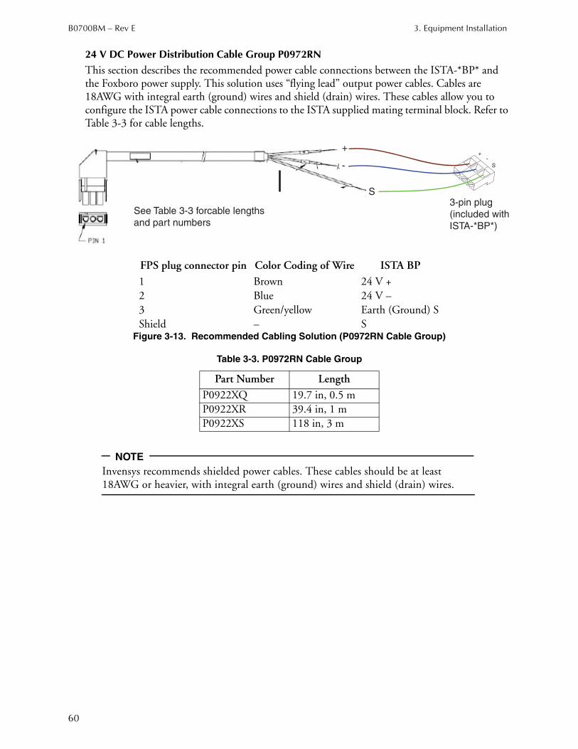
B0700BM – Rev E 3. Equipment Installation
60
24 V DC Power Distribution Cable Group P0972RN
This section describes the recommended power cable connections between the ISTA-*BP* and the Foxboro power supply. This solution uses “flying lead” output power cables. Cables are 18AWG with integral earth (ground) wires and shield (drain) wires. These cables allow you to configure the ISTA power cable connections to the ISTA supplied mating terminal block. Refer to Table 3-3 for cable lengths.
Figure 3-13. Recommended Cabling Solution (P0972RN Cable Group)
NOTE
Invensys recommends shielded power cables. These cables should be at least 18AWG or heavier, with integral earth (ground) wires and shield (drain) wires.
FPS plug connector pin Color Coding of Wire ISTA BP
1 Brown 24 V +
2 Blue 24 V –
3 Green/yellow Earth (Ground) S
Shield – S
Table 3-3. P0972RN Cable Group
Part Number Length
P0922XQ 19.7 in, 0.5 m
P0922XR 39.4 in, 1 m
P0922XS 118 in, 3 m
+
-
S
+-
S
See Table 3-3 forcable lengths
and part numbers
3-pin plug
(included with
ISTA-*BP*)
3. Equipment Installation B0700BM – Rev E
61
ISTA-*BP* HART Multiplexer ConnectionEach ISTA-*BP* for analog inputs or analog outputs can be connected to a H-System HART-Multiplexer solution using the HiD Mux 2700 in connection with the HART communication board HIATB01-HART-2x16 (for dual boards supporting 2x 16 channels) or HIATB01-HART-4x08 (for simplex or redundant boards supporting 4x 8 channels). Connection between the HART communication board and the ISTA-*BP* is established by using a standard 37-Pin Sud-D connector.
NOTE
This function should not be combined with HART FBM214, 215, 216 and 218) to prevent communication conflicts.
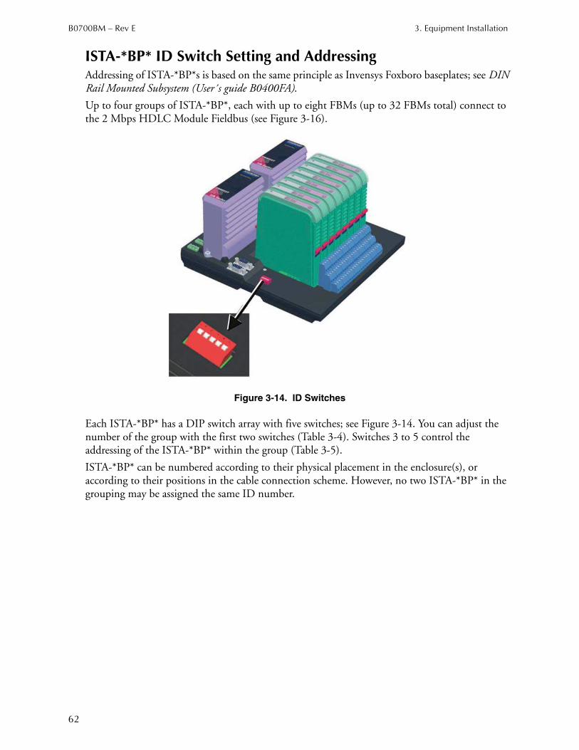
B0700BM – Rev E 3. Equipment Installation
62
ISTA-*BP* ID Switch Setting and AddressingAddressing of ISTA-*BP*s is based on the same principle as Invensys Foxboro baseplates; see DIN Rail Mounted Subsystem (User´s guide B0400FA).
Up to four groups of ISTA-*BP*, each with up to eight FBMs (up to 32 FBMs total) connect to the 2 Mbps HDLC Module Fieldbus (see Figure 3-16).
Figure 3-14. ID Switches
Each ISTA-*BP* has a DIP switch array with five switches; see Figure 3-14. You can adjust the number of the group with the first two switches (Table 3-4). Switches 3 to 5 control the addressing of the ISTA-*BP* within the group (Table 3-5).
ISTA-*BP* can be numbered according to their physical placement in the enclosure(s), or according to their positions in the cable connection scheme. However, no two ISTA-*BP* in the grouping may be assigned the same ID number.
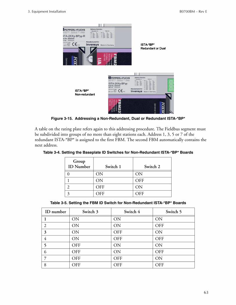
3. Equipment Installation B0700BM – Rev E
63
Figure 3-15. Addressing a Non-Redundant, Dual or Redundant ISTA-*BP*
A table on the rating plate refers again to this addressing procedure. The Fieldbus segment must be subdivided into groups of no more than eight stations each. Address 1, 3, 5 or 7 of the redundant ISTA-*BP* is assigned to the first FBM. The second FBM automatically contains the next address.
Table 3-4. Setting the Baseplate ID Switches for Non-Redundant ISTA-*BP* Boards
GroupID Number Switch 1 Switch 2
0 ON ON
1 ON OFF
2 OFF ON
3 OFF OFF
Table 3-5. Setting the FBM ID Switch for Non-Redundant ISTA-*BP* Boards
ID number Switch 3 Switch 4 Switch 5
1 ON ON ON
2 ON ON OFF
3 ON OFF ON
4 ON OFF OFF
5 OFF ON ON
6 OFF ON OFF
7 OFF OFF ON
8 OFF OFF OFF
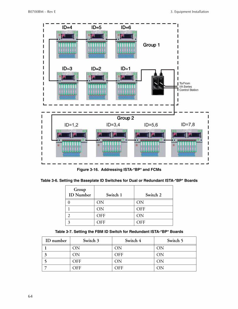
B0700BM – Rev E 3. Equipment Installation
64
Figure 3-16. Addressing ISTA-*BP* and FCMs
Table 3-6. Setting the Baseplate ID Switches for Dual or Redundant ISTA-*BP* Boards
GroupID Number Switch 1 Switch 2
0 ON ON
1 ON OFF
2 OFF ON
3 OFF OFF
Table 3-7. Setting the FBM ID Switch for Redundant ISTA-*BP* Boards
ID number Switch 3 Switch 4 Switch 5
1 ON ON ON
3 ON OFF ON
5 OFF ON ON
7 OFF OFF ON

3. Equipment Installation B0700BM – Rev E
65
Ethernet, Fiber Optic, and Module Bus Cable Runs in Hazardous Areas
The module bus, in shielded twisted-pair or fiber optic form, can be run in Division 2/Zone 2 hazardous areas.

B0700BM – Rev E 3. Equipment Installation
66
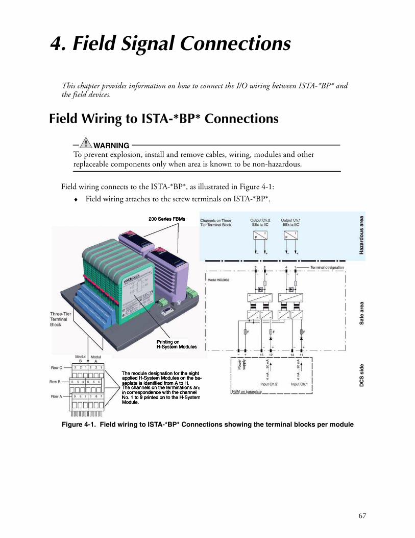
67
4. Field Signal Connections
This chapter provides information on how to connect the I/O wiring between ISTA-*BP* and the field devices.
Field Wiring to ISTA-*BP* Connections
WARNING!
To prevent explosion, install and remove cables, wiring, modules and other replaceable components only when area is known to be non-hazardous.
Field wiring connects to the ISTA-*BP*, as illustrated in Figure 4-1:
♦ Field wiring attaches to the screw terminals on ISTA-*BP*.
Figure 4-1. Field wiring to ISTA-*BP* Connections showing the terminal blocks per module
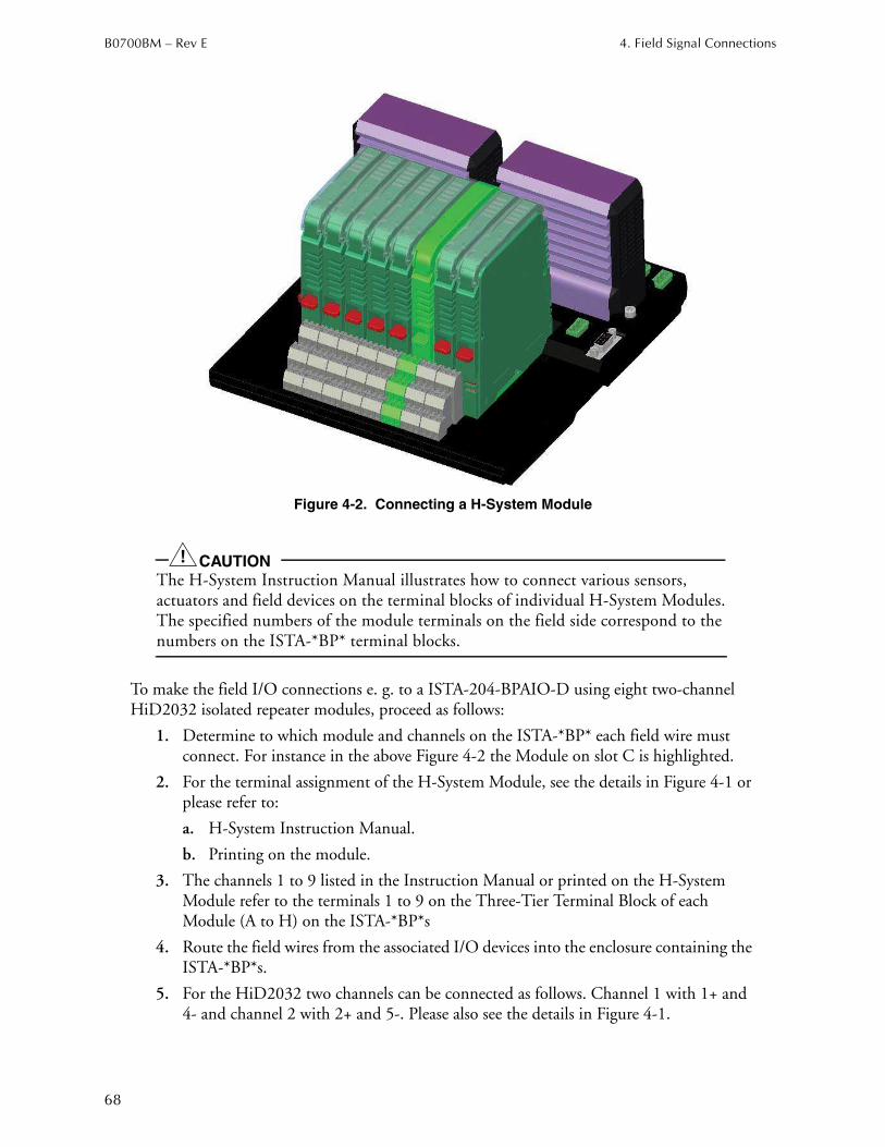
B0700BM – Rev E 4. Field Signal Connections
68
Figure 4-2. Connecting a H-System Module
CAUTION!
The H-System Instruction Manual illustrates how to connect various sensors, actuators and field devices on the terminal blocks of individual H-System Modules. The specified numbers of the module terminals on the field side correspond to the numbers on the ISTA-*BP* terminal blocks.
To make the field I/O connections e. g. to a ISTA-204-BPAIO-D using eight two-channel HiD2032 isolated repeater modules, proceed as follows:
1. Determine to which module and channels on the ISTA-*BP* each field wire must connect. For instance in the above Figure 4-2 the Module on slot C is highlighted.
2. For the terminal assignment of the H-System Module, see the details in Figure 4-1 or please refer to:
a. H-System Instruction Manual.
b. Printing on the module.
3. The channels 1 to 9 listed in the Instruction Manual or printed on the H-System Module refer to the terminals 1 to 9 on the Three-Tier Terminal Block of each Module (A to H) on the ISTA-*BP*s
4. Route the field wires from the associated I/O devices into the enclosure containing the ISTA-*BP*s.
5. For the HiD2032 two channels can be connected as follows. Channel 1 with 1+ and 4- and channel 2 with 2+ and 5-. Please also see the details in Figure 4-1.
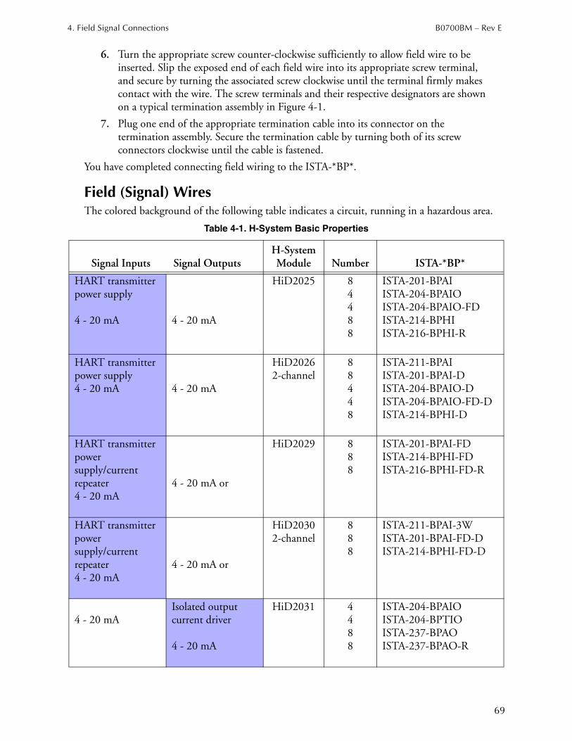
4. Field Signal Connections B0700BM – Rev E
69
6. Turn the appropriate screw counter-clockwise sufficiently to allow field wire to be
inserted. Slip the exposed end of each field wire into its appropriate screw terminal, and secure by turning the associated screw clockwise until the terminal firmly makes contact with the wire. The screw terminals and their respective designators are shown on a typical termination assembly in Figure 4-1.
7. Plug one end of the appropriate termination cable into its connector on the termination assembly. Secure the termination cable by turning both of its screw connectors clockwise until the cable is fastened.
You have completed connecting field wiring to the ISTA-*BP*.
Field (Signal) Wires The colored background of the following table indicates a circuit, running in a hazardous area.
Table 4-1. H-System Basic Properties
Signal Inputs Signal OutputsH-System Module Number ISTA-*BP*
HART transmitter power supply
4 - 20 mA 4 - 20 mA
HiD2025 84488
ISTA-201-BPAIISTA-204-BPAIOISTA-204-BPAIO-FDISTA-214-BPHIISTA-216-BPHI-R
HART transmitter power supply4 - 20 mA 4 - 20 mA
HiD20262-channel
88448
ISTA-211-BPAIISTA-201-BPAI-DISTA-204-BPAIO-DISTA-204-BPAIO-FD-DISTA-214-BPHI-D
HART transmitter power supply/current repeater4 - 20 mA
4 - 20 mA or
HiD2029 888
ISTA-201-BPAI-FDISTA-214-BPHI-FDISTA-216-BPHI-FD-R
HART transmitter power supply/current repeater4 - 20 mA
4 - 20 mA or
HiD20302-channel
888
ISTA-211-BPAI-3WISTA-201-BPAI-FD-DISTA-214-BPHI-FD-D
4 - 20 mAIsolated output current driver
4 - 20 mA
HiD2031 4488
ISTA-204-BPAIOISTA-204-BPTIOISTA-237-BPAOISTA-237-BPAO-R
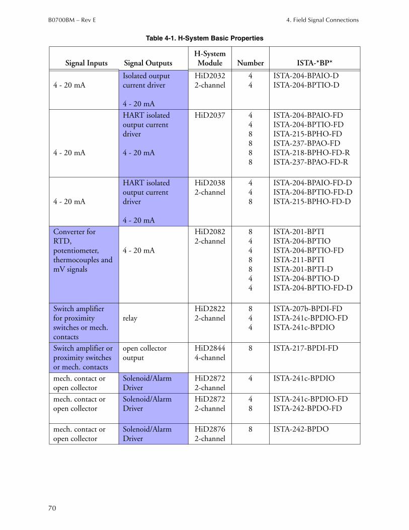
B0700BM – Rev E 4. Field Signal Connections
70
4 - 20 mAIsolated output current driver
4 - 20 mA
HiD20322-channel
44
ISTA-204-BPAIO-DISTA-204-BPTIO-D
4 - 20 mA
HART isolated output current driver
4 - 20 mA
HiD2037 448888
ISTA-204-BPAIO-FDISTA-204-BPTIO-FDISTA-215-BPHO-FDISTA-237-BPAO-FDISTA-218-BPHO-FD-RISTA-237-BPAO-FD-R
4 - 20 mA
HART isolated output current driver
4 - 20 mA
HiD20382-channel
448
ISTA-204-BPAIO-FD-DISTA-204-BPTIO-FD-DISTA-215-BPHO-FD-D
Converter for RTD, potentiometer, thermocouples and mV signals
4 - 20 mA
HiD20822-channel
8448844
ISTA-201-BPTIISTA-204-BPTIOISTA-204-BPTIO-FDISTA-211-BPTIISTA-201-BPTI-DISTA-204-BPTIO-DISTA-204-BPTIO-FD-D
Switch amplifierfor proximity switches or mech. contacts
relayHiD28222-channel
844
ISTA-207b-BPDI-FDISTA-241c-BPDIO-FDISTA-241c-BPDIO
Switch amplifier or proximity switches or mech. contacts
open collector output
HiD28444-channel
8 ISTA-217-BPDI-FD
mech. contact or open collector
Solenoid/Alarm Driver
HiD28722-channel
4 ISTA-241c-BPDIO
mech. contact or open collector
Solenoid/Alarm Driver
HiD28722-channel
48
ISTA-241c-BPDIO-FDISTA-242-BPDO-FD
mech. contact or open collector
Solenoid/Alarm Driver
HiD28762-channel
8 ISTA-242-BPDO
Table 4-1. H-System Basic Properties
Signal Inputs Signal OutputsH-System Module Number ISTA-*BP*
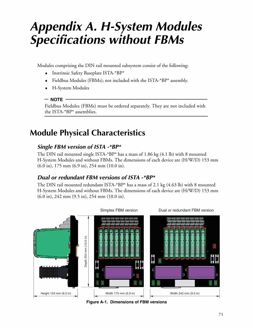
71
Appendix A. H-System Modules Specifications without FBMs
Modules comprising the DIN rail mounted subsystem consist of the following:
♦ Instrinsic Safety Baseplate ISTA-*BP*
♦ Fieldbus Modules (FBMs); not included with the ISTA-*BP* assembly.
♦ H-System Modules
NOTE
Fieldbus Modules (FBMs) must be ordered separately. They are not included with the ISTA-*BP* assemblies.
Module Physical Characteristics
Single FBM version of ISTA -*BP*The DIN rail mounted single ISTA-*BP* has a mass of 1.86 kg (4.1 lb) with 8 mounted H-System Modules and without FBMs. The dimensions of each device are (H/W/D) 153 mm (6.0 in), 175 mm (6.9 in), 254 mm (10.0 in).
Dual or redundant FBM versions of ISTA -*BP*The DIN rail mounted redundant ISTA-*BP* has a mass of 2.1 kg (4.63 lb) with 8 mounted H-System Modules and without FBMs. The dimensions of each device are (H/W/D) 153 mm (6.0 in), 242 mm (9.5 in), 254 mm (10.0 in).
Figure A-1. Dimensions of FBM versions
Depth
254 m
m (
10.0
in)
Width 175 mm (6.9 in)Height 153 mm (6.0 in) Width 242 mm (9.5 in)
Simplex FBM version Dual or redundant FBM version
B0700BM – Rev E Appendix A. H-System Modules Specifications without
72
Power Supply
ISTA-*BP*: 24 V dc
Fault Bus: 30 V with 10 mA
Module Temperature, Relative Humidity, and Contamination
Temperature, relative humidity, and contamination specifications for the DIN rail mounted FBM subsystem modules are as follows:
Temperature
Operating: 0 to +60° C (32 to +140° F)
Storage: -20 to +70° C (-4 to +158° F).
Relative Humidity
5 to 90%, noncondensing (applies for both operating and storage environments)
The modules are intended for Overvoltage Category II, Pollution Degree 2 as defined in IEC/EN 60664-1.
Module VibrationThe vibration specification for the DIN rail mounted FBM subsystem modules is 0.75 g (at 5 to 200 Hz) or 1 g (58 to 150 Hz) as defined in IEC 60068-2-6.
The shock resistance of the interface board is 15G, 11 ms (currentless state, sinusoidal half cycle) in acc. with IEC 60068-2-27.
Module Heat Dissipation and Power ConsumptionRefer to Chapter “Functional and Environmental Considerations” for the heat dissipation and power consumption figures for the 200 Series FBM and H-System Modules in the DIN rail mounted FBM Subsystem. Also refer to that section for thermal loading for the enclosures housing these modules.
Electromagnetic Compatibility (EMC)
European EMC Directive 2004/180/ECThe H-System Modules and ISTA-*BP* fulfill the regulatories:
♦ EN 61326-1
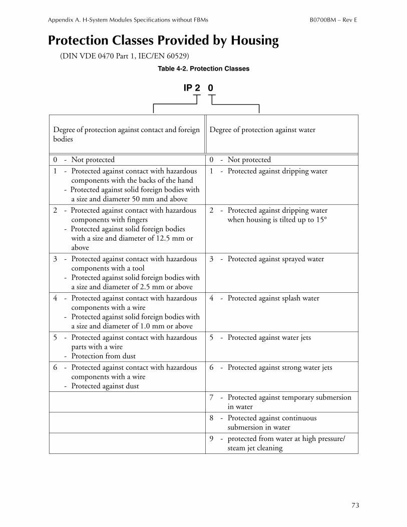
Appendix A. H-System Modules Specifications without FBMs B0700BM – Rev E
73
Protection Classes Provided by Housing
(DIN VDE 0470 Part 1, IEC/EN 60529)
Table 4-2. Protection Classes
Degree of protection against contact and foreign bodies
Degree of protection against water
0 - Not protected 0 - Not protected
1 - Protected against contact with hazardous components with the backs of the hand
- Protected against solid foreign bodies with a size and diameter 50 mm and above
1 - Protected against dripping water
2 - Protected against contact with hazardouscomponents with fingers
- Protected against solid foreign bodieswith a size and diameter of 12.5 mm or above
2 - Protected against dripping waterwhen housing is tilted up to 15°
3 - Protected against contact with hazardous components with a tool
- Protected against solid foreign bodies with a size and diameter of 2.5 mm or above
3 - Protected against sprayed water
4 - Protected against contact with hazardouscomponents with a wire
- Protected against solid foreign bodies with a size and diameter of 1.0 mm or above
4 - Protected against splash water
5 - Protected against contact with hazardous parts with a wire
- Protection from dust
5 - Protected against water jets
6 - Protected against contact with hazardouscomponents with a wire
- Protected against dust
6 - Protected against strong water jets
7 - Protected against temporary submersion in water
8 - Protected against continuoussubmersion in water
9 - protected from water at high pressure/ steam jet cleaning
IP 2 0

B0700BM – Rev E Notes
74

Notes B0700BM – Rev E
75

Printed in U.S.A. 1212
IPS Corporate Headquarters5601 Granite Parkway Suite 1000Plano, TX 75024United States of Americawww.ips.invensys.com
Foxboro Global Client SupportInside U.S.: 1-866-746-6477Outside U.S.: 1-508-549-2424 orcontact your local Foxboro representative.Facsimile: 1-508-549-4999