iadc inspection list
DESCRIPTION
Iadc Inspection ListTRANSCRIPT

Table of Contents Page 1 of 61
(i) Summary of Recommendations
(ii) Report Sections
1. Section 1 - Drilling Equipment
1.1 Derrick & Substructure1.2 Casing Stabbing Board1.3 Crown Block Assembly1.4 Traveling Block Assembly1.5 Top Drive Drilling System1.6 Swivel1.7 Drawworks1.8 Auxiliary Brake, Electric1.9 Sand Reel1.10 Rotary Table Assembly1.11 Drilling Line Anchor1.12 Drilling Line1.13 Driller's Console & Instrumentation1.14 Ton-Mile Indicator1.15 Drilling Recorder1.16 Rig Floor Hydraulic System1.17 Wire Line Unit1.18 Cement Lines (Piping, hoses or chicksans)1.19 Hand Tools
2. Section 2 - Drill String & Handling Equipment
2.1 Slips, Drill Pipe, Drill Collars, Elevators & Casing2.2 Elevator Links2.3 Tongs, Drill Pipe, Drill Collars & Casing (Manual)2.4 Tongs & Casing (Power)2.5 Safety Clamps2.6 Spinning Wrench2.7 Pipe Racking and Handling System2.8 Hydraulic Cathead2.9 Kelly2.10 Kelly Drive Bushing2.11 Master Bushings & Insert Bowls2.12 Upper Kelly Valve or IBOP Valve2.13 Lower Kelly Valve or IBOP Valve2.14 Rig Floor "Gray" Safety Check Valve2.15 Rig Floor "Full Opening" Safety Valve2.16 Drill Pipe & HWDP2.17 Drill Collars2.18 Drilling Subs & Crossovers2.19 Crossover for Rig Floor Stab-In Valves2.20 Fishing Tools
3. Section 3 - Mud System
3.1 Mud Pumps3.2 Mud Pits3.3 Mud Mixing & Transfer System3.4 Mud Shearing System3.5 Pit Volume Totalizer System
TABLE OF CONTENTS

Table of Contents Page 2 of 61
3.6 Mud Pit Agitators3.7 Mud Process Pits3.8 Shale Shakers3.9 Desander3.10 Desilter3.11 Mud Cleaner3.12 Vaccum Degasser3.13 Poor Boy Mud/Gas Separator3.14 Mud Flow Line Return and Bell Nipple3.15 Trip Tank3.16 Bulk Storage and Transfer System3.17 Stand Pipe Manifold, HP Mud Piping & Valves
4. Section 4 - Engine Room & Associated Equipment
4.1 Engine Room Ventilation System4.2 Main Diesel Engines4.3 Engine Instruments4.4 Main Diesel Engine Cooling4.5 Engine Monitoring System Alarms4.6 General4.7 Fuel Transfer Pump4.8 Clean Fuel Transfer Pump4.9 Fuel Centrifuge4.10 Fuel Piping & Valves4.11 Lube Oil Piping & Valves4.12 Potable Water Makers & Purification4.13 Water Purification & Treatment4.14 Potable Water Transfer Pumps & Pressure Reservoir4.15 Rig Service Air System4.16 Air Dryers4.17 Air Receivers4.18 Bilge Monitor4.19 Sewage Treatment System4.20 Pumps
5. Section 5 - Electrical Systems
5.1 Main & Emergency AC Generator Switchboard5.2 Generators5.3 AC Motors5.4 Power Transformers5.5 DC Drive Motors5.6 DC Generators5.7 Main & Emergency Distribution AC Switchboards5.8 Wireways, MCT's, Bulkhead & Deck Penetrations5.9 Shore Power Connection System5.10 Welding Outlets5.11 General Rig Lighting & Wiring5.12 Aircraft Warning Lights5.13 Navigation & Running Lights5.14 Helicopter Area Lighting5.15 Sound Powered Telephone5.16 Rig Telephone & PA System5.17 TV Systems5.18 Emergency Generator
6. Section 6 - Marine Systems
6.1 Marine Documentation6.2 Manufacturer's & Third Party Documentation6.3 Navigation & Communication Equipment6.4 Storage Areas

Table of Contents Page 3 of 61
6.5 Fuel Tanks6.6 Ballast Control System6.7 Stability6.8 Hull6.9 Cathodic Protection (Anodes)6.10 Exhaust Stacks6.11 Hatches, Windows, Manholes, Openings & Coamings6.12 Walkays/Platforms6.13 Superstructures6.14 Helicopter Deck /Fueling System6.15 Anchor Racks6.16 Weather Protection6.17 Ventilation (Accomodations & Rig Area Compartments)6.18 Tank Gauging System6.19 Tank Vent & Sounding Tube System6.20 Bilge Piping & Valves6.21 General6.22 Mooring Winch/Windlass Combination6.23 Mooring System Control6.24 Primary & Auxiliary Brake System6.25 Controls, Piping & Valves6.26 Emergency Release System6.27 Mooring Tension Indicating System6.28 Tow Line/Bridle6.29 Emergency Tow Line6.30 Work Boat Back-down/Tie-up System6.31 Anchors6.32 Fairleader6.33 Mooring Wire6.34 Pendant Lines6.35 Chain Link, Kenter/Connecting Links & Shackles6.36 Buoys6.37 Slings & Shackles6.38 Cranes6.39 Billy Pugh Transfer Net (Personnel)6.40 Air Hoist (Tuggers)6.41 Man-Riding Tuggers6.42 Fork Lift/Pallet Lift6.43 Mechanical Winches6.44 Chain Falls6.45 Cargo Containers (Box, Net, Cargo Basket & Burn Baskets)6.46 Hoses - Bulk Mud, Water & Oil6.47 Quarters, Shop Furnishings & Equipment Inspection6.48 Inspection6.49 General Accomodation Room Inspection6.50 Air Conditioning System (Main Quarters)6.54 Galley Exhaust(s)6.52 Quarters' Ventilation System6.53 Fans6.54 Ducting6.55 Refrigeration Compressor System6.56 Walk-in Coolers6.57 Walk-in Freezer6.58 Air Conditioning Pump/Brine Pump (with Motor)6.59 Welding & Burning Practices, Procedures & Equipment
7. Section 7 - Third Party Equipment
7.1 Cementing System7.2 Well Test Piping & Valves7.3 Burners7.4 Burner Booms

Table of Contents Page 4 of 61
8. Section 8 - Motion Compensating Equipment
8.1 Riser Tensioners - General8.2 Shaffer Riser Tensioners8.3 Guide Lines, Pod/Messenger Line Tensioners8.4 Motion Compensator - General8.5 Shaffer Compensator8.6 High Pressure Air System
9. Section 9 - Maintenance System Evaluation
9.1 Management Organization & Administration9.2 Measures of Effectiveness9.3 Work Control9.4 Management Information System9.5 Personnel9.6 Logistics Support9.7 Maintenance Tasks / Maintenance Engineering9.8 Spare Parts
10. Section 10 - Subsea Blowout Prevention Equipment
10.1 General Requirements10.2 Pressure Rating10.3.1 Ram #1 Blind/Shear Ram10.3.2 Ram #2 - 3 1/2" x 5 1/2" VBR's10.3.3 Ram #3 - 5" Pipe Ram10.3.4 Ram #4 Pipe Rams10.4.1 Annular Preventers, Upper10.4.2 Annular Preventers, Lower10.5 BOP Stack Mounted Valves10.6 BOP Control Unit & Remote Panels10.7 Choke & Kill Hoses10.8 Choke Manifold10.9 Manual Choke10.10 Remote Choke & Controls10.11 Diverter System10.12 Clamps, Flanges & Fasteners10.13 Ring Gaskets & Grooves10.14 Connectors10.15 Riser10.16 Telescopic Joint10.17 Riser Adapter10.18 Ball Joint10.19 Rig Positioning Equipment10.20 ROV10.21 BOP Handling System10.22 Rig Floor, Procedures & Regulations10.23 Bulletins10.24 Preventinve Maintenance10.25 Welding
11. Section 11 - Safety Survey
11.1 General Requirements11.2 Personal Protective Equipment11.3 Hospital11.4 Lifesaving Equipment11.5 Lifeboats11.6 Life Rafts11.7 Rescue Boat11.8 Life Preservers & Life Rings11.9 Self-Contained Breathing Apparatus
Table of Contents Page 5 of 61
11.10 Fire Pumps11.11 Fire Fighting Equipment11.12 Inert Gas Fire Fighting Systems11.13 Foam Fire Fighting Systems11.14 Alarms & Detection11.15 Plans, Permits & Supervisor's Requirements11.16 Drills11.17 Records11.18 H2S Requirements
12. Section 12 - Environmental Audit
12.1 Environmental Management12.2 General Discharge Control12.3 Rig Floor Discharge12.4 Mud Pump Room12.5 Mud Pit Room12.6 Sack Room/Mud Mixing Area12.7 Shakers12.8 Sand Traps12.9 Trip Tank12.10 Bulk & Fluid Transfer Hoses12.11 Bulk System12.12 Waste Containers12.13 Mud Lab / Mud Logging / Wireline Unit12.14 Koomey Unit12.15 Cement Unit12.16 Production Test Areas12.17 Engine Room12.18 Accommodations12.19 Main Deck12.20 Firefighting12.21 Waste Management12.22 Mud System12.23 Storage Tanks12.24 Diesel Filters/Centrifuges12.25 Oil/Fuel Transfer12.26 Sewage Treatment Equipment12.27 Refrigeration Units (CFC's)12.28 Spill Contingency12.29 Maintenance & Housekeeping

Summary of Recommendations Page 6 of 61
DATE
Item # Inspection Requirement Findings Recommendations Note1 Main Engines, 1,2,3,42 Draw Works and Elmago break3 Jacking System4 Mud Pump power end5 Mud Pump Fuild End6 Transverse skidding7 Forklift8 Air Winches9 Iron Rough Neck
10 Heat exchanger for Drawworks and Elmago break
Summary of Recommendations
Section 1 Drilling Equipment
1 Mechanical Major Work Scope

Summary of Recommendations Page 7 of 61
Item # Inspection Requirement Findings Recommendations Note
EMERGENCY GENERATOR
5
6
2 Electrical Major Work Scope
GENERATOR 1
AUXILIARY GENERATOR
1
GENERATOR 22
GENERATOR 33
GENERATOR 44

Summary of Recommendations Page 8 of 61
8 SCR
MAIN SWITCHBOARD
DRAW WORKS
7
9
TOP DRIVE10
Summary of Recommendations Page 9 of 61
15 SEWAGE TREATMENT PLANT16 PIPE RACKING SYSTEM
13
SAFETY EQUIPMENT14
MUD PUMPS11
JACKING SYSTEM12
AIR - COND / REFRIGERATION

Summary of Recommendations Page 10 of 61
Item # Inspection Requirement Findings Recommendations Note1 Jetting line inspection2 UWILD for spud can3 Pre-load tanks4 Cathodic Protection (Anodes) for legs5 Anchors6 5 Ton crane7 Cantiliver and substructure8 Bulk system9 Radios and communication system
Item # Inspection Requirement Findings Recommendations Note1 Smoke sensors to be provided in the
accomodation area2 Emergency lights not available in escape routes3 FRC (Fst Rescue Craft)4 Paint locker on main deck (port side)5 Portable fire extingishers onboard6 SCBA sets and Cascade system7 Derrick man escape device (Gerinimo)8 Photo illuminated signs9 Fire stations10 Pyrotechnics11 STP12 Incinerator13 Oily water seperator
1 Helideck2 Helideck perimeter lights3 Perimeter nets rusted.4 Helicopter crash5 Fire Fighting
Galley1 Electrical connection2 Hotplates not working3 Galley shutter4 Fire suppression system5 Drain covers6 Mantrap alarm in Veg chiller7 Freezer
CRANE1 Load test2 Load cell3 Cameras4 Fire Fighting5 Comunication with deck team6 Internal telecom (paging)7 Emergency STOP8 whipline9 Pedal acceleration10 AC in crane operator cabin
ACCOMODATION1 Sound proofing for accomodation2 External windows in accomodation3 Ceiling lights4 External water tighht doors in accomodation areas5 Emergency lights6 Photo illuminated signs7 Sink drainage8 additional shlves9 Air conditioning10 Bathroom sink drain
Walkways1 Heliedeck gratting2 Skirting on main deck3 Pump room4 Sack room5 Rack choke system6 Handrails
HSE
Helideck
3 Marine Major Work Scope

Section 1 Page 11 of 61
Item # Inspection Requirement Findings Recommendations Note
1.1
1.1.1 Complete inspection of derrick, substructure andraising or telescoping system per API RP 4G.
1.1.2 Confirm NDE performed and SWL marked on allPadeyes.
1.1.3Inspect ladder. Check that spacing of rungs arestandard. Check that ladder is properly secured toderrick.
1.1.4Inspect fingers and diving board. Make sure they areproperly secured and have safety wires attached.
1.2
1.2.1 Check condition of board in general. Examine hoist,cables or hydraulics and all safety devices.
1.2.2 Confirm secondary means of stopping board if liftingmechanism fails.
1.2.3 Function board through entire range of travel and fullytest all safety devices.
1.2.4 Confirm driller has an unobstructed view of casingstabber.
1.3
1.3.1 Complete inspection of crown and water table area perAPI RP 4G.
1.3.2 Record date of last NDE as per API RP 8B.
1.3.3Confirm crown protection is in place and bumperblocks are wrapped in heavy-duty wire mesh orexpanded metal screen.
1.3.4Use gauge and inspect sheaves for wear in grooves andcheck sheaves for excess movement to identify badlyworn bearings.
1.3.5 Raise and lower blocks while visually observingsheaves for misalignment and loose or worn bearings.
1.3.6 Check grease fittings and verify proper lubrication.
1.3.7Confirm sheaves adequately protected by jumper barsto ensure that drilling line cannot jump from sheaves inevent of jarring or other situations.
1.3.8 Check condition of auxiliary line sheaves, safety slings.Confirm all shackles have safety pins.
1.3.9Confirm auxiliary sheave grease lines manifoldtogether or are otherwise easily reached so they can begreased in a safe manner.
1.41.4.1 Record date of last NDE as per API RP 8B.1.4.2 Check grease fittings and verify proper lubrication.
1.4.3 Raise and lower blocks numerous times. Observe forany unusual noise or movement on tracking system.
1.4.4Check traveling block guide track to insure it is straightand guide rollers ride freely during movement up anddown.
1.4.5 Confirm track rollers guarded so they can't fall to rigfloor if they come loose.
1.4.6Use gauge to inspect sheaves for wear in grooves andcheck sheaves for excess movement to identify badlyworn bearings.
Section 1 Drilling Equipment
As a minimum API RP 8B (section 2) Category IV recommends every five years; disassembly to extent necessary to conduct NDEof all primary load carrying components as defined by manufacturer. Owner or user of equipment should develop his own scheduleof inspections based on experience, manufacturer's recommendations, and consideration for one or more of following factors:environment; load cycles; regulatory requirements; operating time; testing; repairs; re manufacture.
Derrick and Substructure
Casing Stabbing Board
Crown Block Assembly
Traveling Hook Block Assembly

Section 1 Page 12 of 61
Item # Inspection Requirement Findings Recommendations Note
1.4.8 When blocks are hung off, is the hookup acceptable?Explain hookup.
1.4.9 Cables and padeyes proper safe working load?1.5
1.5.2 Record date of last NDE as per API RP 8B andmanufacturer.
1.5.3 Function test pipe handler.
1.5.4 Function IBOP valves and pressure test valves toMWP.
1.5.5 Test kelly hose and swivel packing to MWP.
1.5.6 Verify proper operation of counter balance and motoralignment cylinder systems.
1.5.7 Test run in forward and reverse in each gear. Checksmoothness of high/low shift mechanism and indicator.
1.5.8 Confirm proper operation of all lights and alarms.
1.5.9 Visually inspect service loop. Confirm availability ofspare conductors.
1.5.10 Confirm compensator hoses properly bundled andtravel unobstructed in derrick.
1.5.11 Function test link tilt assembly and check for air leaks.
1.5.12 Record AC drive motor data insulation resistance.
1.5.13
Perform visual inspection of top drive power panel.Check all contactors, relays, power supplies, andterminal boards to see that they are properly markedand that all screws and bolts are tight.
1.5.14 Verify proper operation of driller's control panel.
1.5.15
Verify proper operation of installed purge loss alarmsystem. Shut off purge air supply, note alarm, checkemergency by-pass operation, let system power down.Turn on air supply to see if system will go through anautomatic purge cycle.
1.5.16 Verify proper operation of retracted position lockmechanism on raised back-up system.
1.5.17 Visually inspect torque beam support chains on PTDrive.
1.6 Swivel1.6.1 Record dates of last NDE as per API RP 8B.1.6.2 Record date and results of last lube oil analysis?
1.6.3 Function test swivel and pressure test Kelly hose, gooseneck and swivel packing to MWP.
1.71.7.1 Record date and results of last lube oil analysis.1.7.2 Confirm NDE of critical areas on brake bands.
1.7.3 Check thickness of brake rims with ultrasonic testerand compare with manufacturers' specifications.
1.7.4 Confirm ducting for drawworks blower motors meetregulatory requirements.
1.7.5Visually inspect all chains and sprockets for wear ordamage as per API SPEC 7F. Max 3% Enlongation.
1.7.6 Visually check alignment of sprockets, bearings andshafts.
1.7.7 Run drawworks to check for leaks of oil or water andcheck for excess vibration.
1.7.8 Function in both low and high transmission and drum.
1.7.9Engage and disengage air clutches several times toverify that they will operate smoothly without slippageor overheating.
1.7.10 Function all air controls at driller's stationindependently and check for leaks.
1.7.11 Check all air connections and hoses for leaks.1.7.12 Check operation of air valves.1.7.13 Operate neutral brake.1.7.14 Inspect oiling system.
Drawworks
Top Drive Drilling System

Section 1 Page 13 of 61
Item # Inspection Requirement Findings Recommendations Note1.7.15 Inspect grease system.
1.7.16Check spear connections to drum shaft and auxiliarybrake. Verify packing condition and check for leaks.
1.7.17 Inspect shift linkage.
1.7.18 Inspect brake linkage. Check for excess play to insurelinkage is not worn.
1.7.19 Confirm tightness of brake lining blocks, bolts, anddrum brake adjustment.
1.7.20 Confirm safety pins and self-locking nuts are in place.
1.7.21 Visually inspect drum grooving wear ring and kick-back rollers.
1.7.22 Function 'Crown-O-Matic' with blocks moving anddetermine if effective.
1.7.23
Make-up and break-out cathead should be pull tested tomake sure of sufficient line pull for all expectedrequirements. Make-up = 8,000# line pull, Break-out =16,000# line pull.
1.7.24 Inspect auxilary brake to drawworks coupling.
1.7.25 Check brake and auxiliary brake alarms for properoperation.
1.7.26Check high temperature and low pressure alarms.
1.7.27 Confirm calibration of temperature and flow gauges.
1.7.28
Inspect drawworks brake cooling system; pumps,piping and valves. Confirm heat dissipation system(fan or heat exchangers) adequate and in goodcondition. Insure cooling water flow is adequate andmeets manufacturer's specifications.
1.7.30 Record DC drive motors insulation resistance.1.8
1.8.1 Minimum insulation resistance to ground is 5 MegOhm per Baylor section 6.5.4.
1.8.2
Coil resistance should be 5.5 Ohm to 6.5 Ohm forbrakes 6032 and smaller. Larger brakes will be 12+Ohm. It is important that readings all be close. Notsome at 5.5 and others at 6.5. In addition same modelscan vary depending on date of manufacture. ConsultBaylor service manual.
1.8.3 Air gaps should be 0.040” to 0.050” for smaller brakes.0.055” to 0.065” on larger brakes.
1.8.4 Insure vents are operating properly.
1.8.5 Confirm engagement lever is locked securely in place.
1.8.6 Insure electric brake works properly and is adequate fordrilling program.
1.91.9.1 Check braking system.1.9.2 Note condition of line and line spooler.1.10
1.10.1 Record date and results of last lube oil analysis.
1.10.2Operate rotary, while observing for noise, oil leakageand vibrations. Use both high and low gears andreverse during this test.
1.10.3 Check for contaminants in lubrication systems.1.10.4 Check operation of brake.1.10.5 Check function of torque limiter and RPM gauge.
1.10.7 Confirm ducting for rotary blower meets regulatoryrequirements.
1.10.8 Record DC drive motor data in section 5.5.
1.10.9Visually inspect all chains and sprockets for wear ordamage as per API SPEC 7F. Visually checkalignment of sprockets.
1.10.10 Record transmission to rotary coupling alignment.1.11
Auxiliary Brake, Electric
Sand Reel
Rotary Table Assembly
Drilling Line Anchor

Section 1 Page 14 of 61
Item # Inspection Requirement Findings Recommendations Note1.11.1 Record date of last NDE as per API RP 8B.1.11.2 Visually check all bolts.1.11.3 Inspect brass on tie-down clamp.1.11.4 Check sensator gap.
1.11.5Check weight indicator for smooth operation increasingand decreasing weight. Erratic operation could indicatedirty or damaged bearings.
1.12
1.12.1 Minimum standards should comply with API RP 9B.
1.12.2 Note condition of drilling line.1.12.3 Record length of line on spool.1.12.4 Review slip and cut drilling line program.1.12.5 Examine condition of wire line guide and rollers.1.13
1.13.1 Confirm equipment meets API RP 500 for hazardousareas.
Drilling Line
Driller's Console and Instrumentation

Section 1 Page 15 of 61
Item # Inspection Requirement Findings Recommendations Note
1.13.2 Conform proper operation of all installed instrumentsincluding the following:
1.13.3 Weight Indicator1.13.4 Electric Torque Meter1.13.5 RPM meter1.13.6 SPM Meter1.13.7 Mud Flow Fill and Stroke Panel
1.13.8 Pressurization Control Valves, Gauges, & Regulators
1.13.9 Mud Pit Volume Totalizer1.13.10 Tong Torque Gauges
1.14
1.14.1Confirm explosion-proof integrity of each indicator andsending unit as per API RP 500 for hazardous areas.
1.15
1.15.1 Check operation and calibration of each function. Notecondition.
1.16
1.16.1 Inspect power units, controls and piping with valvesand record any deficiencies.
1.171.17.1 Operate and record any deficiencies.
1.17.2
Record size and length of .092 wire. Perform twist teston 10 inch section of wire. Minimum is 23 twists forstandard strength .092 wire. Consult National Standardchart for other sizes or grades..
1.18
1.18.1 View documentation and record date of last inspection.
1.18.2 Test to MWP.1.19
1.19.1 Is supply of hand tools adequate?1.19.2 Are tools stored and maintained properly?
Cement Lines, (piping, hoses or chicksans)
Hand Tools
Ton-Mile Indicator
Drilling Recorder
Rig Floor Hydraulic Power System
Wire Line Unit

Section 2 Page 16 of 61
Item # Inspection Requirement Findings Recommendations Note
2.1
2.1.1 Does rig have current copy of IADC Drilling Manual?
2.1.2 Reference IADC drilling manual, Section E.
2.1.3 Are handling tools marked with a unique ID number soequipment can be matched to documentation?
2.1.4 Verify that appropriately sized slips are available foreach size of drill pipe to be used.
2.1.5 Clean and well-lubricated? General condition?2.1.6 Any obvious cracks, dings or deformation?2.1.7 Record date of last NDE for DP slips.2.1.8 Record date of last NDE for DC slips.2.1.9 Record date of last NDE for casing slips.
2.1.10 Check slips for loose or worn hinge and handle pins.
2.1.11 All pins locked in place with cotter keys?2.1.12 Check inserts and insert slots for damage or wear.
2.1.13 Are spare sets of inserts, dies, liners, pins, and cotterkeys available?
2.1.142.1.15 Comment on condition and record last NDE.2.1.16 Elevators, Drill Pipe, Drill Collar and Casing2.1.17 Record date of last NDE on DP elevators.2.1.18 Record date of last NDE on DC elevators.2.1.19 Record date of last NDE on casing elevators.2.1.20 Visually inspect elevators.2.1.21 General condition? Clean, well maintained?
2.1.22Check ears, pins, bore, latch and latch lug for cracks,dings, or excessive wear and proper operation.
2.1.23
2.1.24 Visual inspection, confirm proper operation and recorddate of last NDE.
2.1.252.1.26 Comment on condition and last NDE.
2.22.2.1 Record date of last NDE as per API RP 8B.
2.2.2Did NDE include inspection of entire surface area oflinks for cracks, bends, or gross dimensional changes?
2.2.3Did NDE include caliper diameters of links,particularly at link ear and elevator contact surfaces?
2.2.4 Did NDE confirm elevator links are of same overalleffective length within 1/8".
2.2.5 Comment on overall condition.
2.3
2.3.1 Record date of last NDE on DP tongs.2.3.2 Record date of last NDE on DC tongs.2.3.3 Record date of last NDE on casing tongs.2.3.4 Visually inspect and comment and condition.2.3.5 Record date of last NDE for tongs back-up posts.2.4
2.4.1 Visual inspection and operationally test and commenton condition.
2.52.5.1 Record date of last NDE.
Elevator Links
Tongs, Drill Pipe, Drill Collars and Casing (manual)
Tongs, Casing (Power)
Safety Clamps
Section 2 Drill String and Handling Equipment
As a minimum API RP 8B (section 2) Category IV recommends every five years; disassembly to extent necessary to conduct NDEof all primary load carrying components as defined by manufacturer. Owner or user of equipment should develop his own scheduleof inspections based on experience, manufacturer's recommendations, and consideration for one or more of following factors:environment; load cycles; regulatory requirements; operating time; testing; repairs; re manufacture.
Slips, Drill Pipe, Drill Collars and Casing
Slips, Spider, Casing
Elevators (Air Operated)
Elevators, Spider, Casing
Section 2 Page 17 of 61
Item # Inspection Requirement Findings Recommendations Note
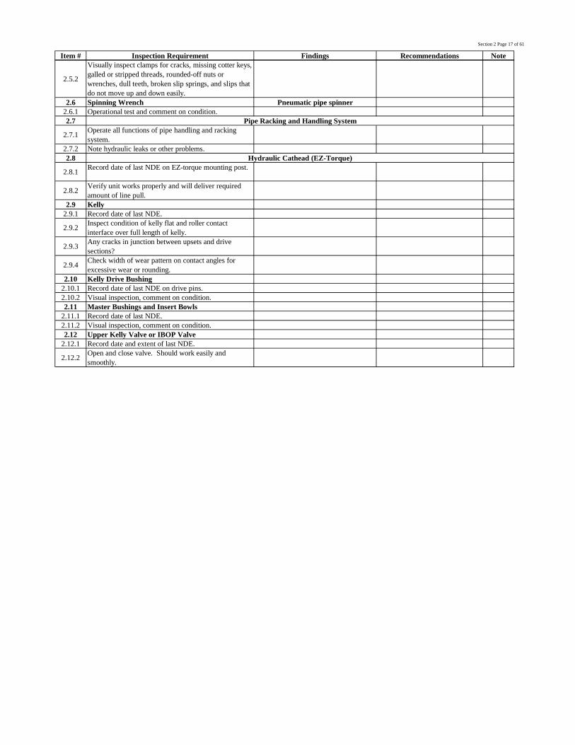
2.5.2
Visually inspect clamps for cracks, missing cotter keys,galled or stripped threads, rounded-off nuts orwrenches, dull teeth, broken slip springs, and slips thatdo not move up and down easily.
2.6 Spinning Wrench Pneumatic pipe spinner2.6.1 Operational test and comment on condition.2.7
2.7.1 Operate all functions of pipe handling and rackingsystem.
2.7.2 Note hydraulic leaks or other problems.2.8
2.8.1 Record date of last NDE on EZ-torque mounting post.
2.8.2 Verify unit works properly and will deliver requiredamount of line pull.
2.9 Kelly2.9.1 Record date of last NDE.
2.9.2 Inspect condition of kelly flat and roller contactinterface over full length of kelly.
2.9.3 Any cracks in junction between upsets and drivesections?
2.9.4 Check width of wear pattern on contact angles forexcessive wear or rounding.
2.10 Kelly Drive Bushing2.10.1 Record date of last NDE on drive pins.2.10.2 Visual inspection, comment on condition.2.11 Master Bushings and Insert Bowls
2.11.1 Record date of last NDE.2.11.2 Visual inspection, comment on condition.2.12 Upper Kelly Valve or IBOP Valve
2.12.1 Record date and extent of last NDE.
2.12.2 Open and close valve. Should work easily andsmoothly.
Pipe Racking and Handling System
Hydraulic Cathead (EZ-Torque)
Section 2 Page 18 of 61
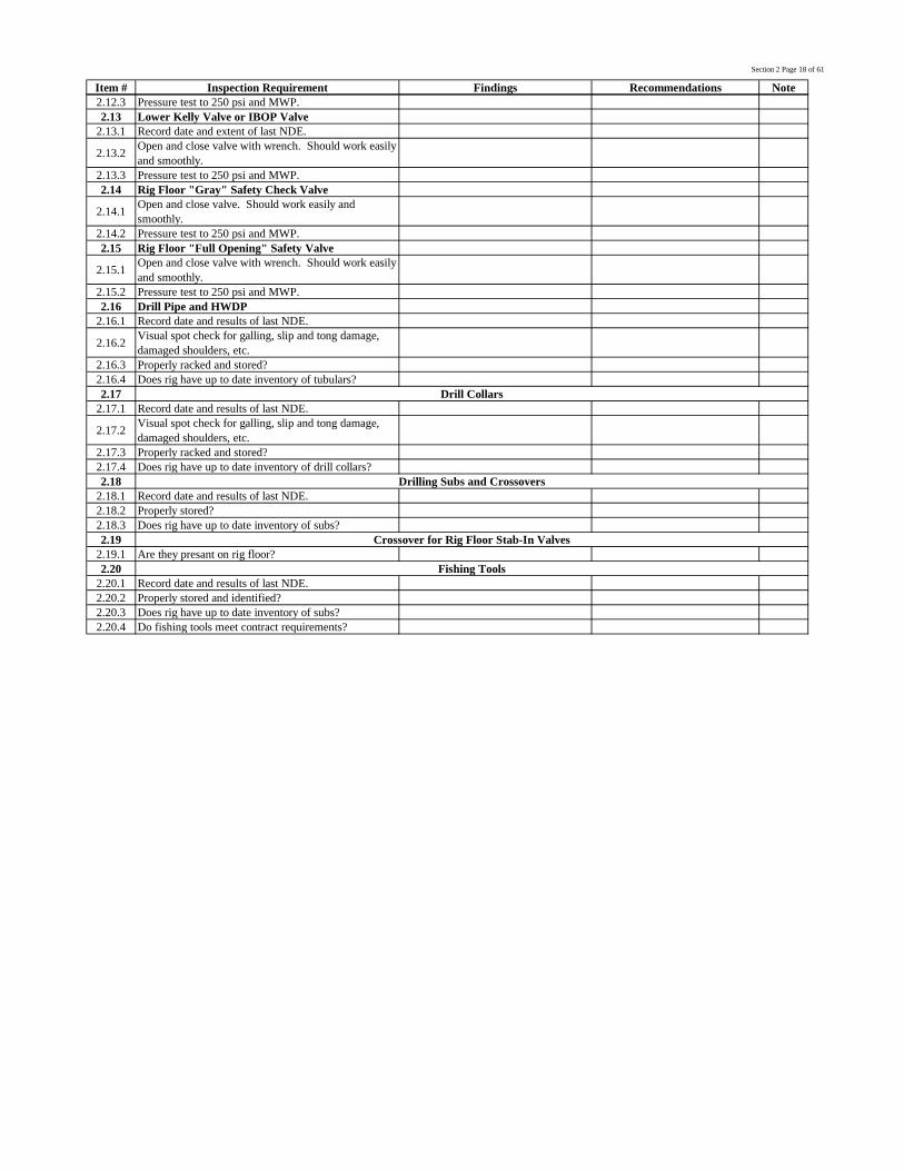
Item # Inspection Requirement Findings Recommendations Note2.12.3 Pressure test to 250 psi and MWP.2.13 Lower Kelly Valve or IBOP Valve
2.13.1 Record date and extent of last NDE.
2.13.2 Open and close valve with wrench. Should work easilyand smoothly.
2.13.3 Pressure test to 250 psi and MWP.2.14 Rig Floor "Gray" Safety Check Valve
2.14.1 Open and close valve. Should work easily andsmoothly.
2.14.2 Pressure test to 250 psi and MWP.2.15 Rig Floor "Full Opening" Safety Valve
2.15.1 Open and close valve with wrench. Should work easilyand smoothly.
2.15.2 Pressure test to 250 psi and MWP.2.16 Drill Pipe and HWDP
2.16.1 Record date and results of last NDE.
2.16.2 Visual spot check for galling, slip and tong damage,damaged shoulders, etc.
2.16.3 Properly racked and stored?2.16.4 Does rig have up to date inventory of tubulars?2.17
2.17.1 Record date and results of last NDE.
2.17.2 Visual spot check for galling, slip and tong damage,damaged shoulders, etc.
2.17.3 Properly racked and stored?2.17.4 Does rig have up to date inventory of drill collars?2.18
2.18.1 Record date and results of last NDE.2.18.2 Properly stored?2.18.3 Does rig have up to date inventory of subs?2.19
2.19.1 Are they presant on rig floor?2.20
2.20.1 Record date and results of last NDE.2.20.2 Properly stored and identified?2.20.3 Does rig have up to date inventory of subs?2.20.4 Do fishing tools meet contract requirements?
Drill Collars
Drilling Subs and Crossovers
Crossover for Rig Floor Stab-In Valves
Fishing Tools
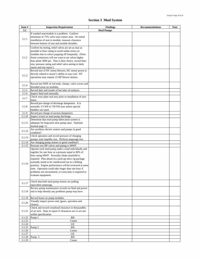
Section 3 Page 19 of 61
Item # Inspection Requirement Findings Recommendations Note3.1
3.1.1
If washed seat/module is a problem: Confirmminimum of 75% valve seat contact area. On initialinstallation of seat in module, measure clearancebetween bottom of seat and module shoulder,minimum = 0.090”.
3.1.2
Confirm by testing, relief valves are set as near aspossible to liner rating to avoid undue stress onmodules due to valves popping off frequently. (Note:Some contractors will not want to set valves higherthan about 3000 psi. That is their choice, record linersize, pressure rating and relief valve setting in dailyreport and trip report.)
3.1.3
Record size of DC motor blowers, DC motor power isdirectly related to motor’s ability to stay cool. HToperations may require 15 HP blower motors.
3.1.4 Record last NDE of rod ends, clamps, valve covers andthreaded areas on modules.
3.1.5 Record date and results of last lube oil analysis.3.1.6 Inspect fluid end internally.
3.1.7 Check wear plate seal area prior to installation of newliners.
3.1.8Record pre-charge of discharge dampeners. It isnormally 1/3 WP to 750 PSI max unless specialbladders are used.
3.1.9 Record pre-charge of suction dampeners.3.1.10 Inspect screen in mud pump discharge.
3.1.11Determine that mud pump lubrication system isadequate for long term slow pump rates. Nationalmanual page 11.
3.1.12 Are auxiliary electric motors and pumps in goodcondition?
3.1.13 Check operation and record pressure of chargingpumps; note impeller size. Perform amperage test.
3.1.14 Are charging pump motors in good condition?3.1.15 Pressure test HP valves and piping to MWP.
3.1.16
Operate each mud pump under a load individually andtogether for one hour at a pressure equal to 80% ofliner rating MWP. Normally choke manifold isrequired. Plan ahead on a jack-up since rig packagenormally needs to be cantilevered out to a drillingposition. Engine performance will be reviewed at sametime. Operation could take longer than one hour ifproblems are encountered, or extra time is required toevaluate equipment.
3.1.17 Check that both mud pump motors are pullingequivalent amperage.
3.1.18Review pump maintenance records on fluid and powerend to help identify any problems pump may have.
3.1.19 Record hours on pump modules.
3.1.20 Visually inspect power end, (gears, sprockets andchains).
3.1.21Check and record crosshead clearance in thousandthsof an inch. State in report if clearances are or are notwithin specification.
3.1.22 Pump 1 RH3.1.23 Center3.1.24 LH3.1.25 Pump 2 RH3.1.26 Center3.1.27 LH3.1.28 Pump 3 RH3.1.29 Center
Section 3 Mud System
Mud Pumps

Section 3 Page 20 of 61
Item # Inspection Requirement Findings Recommendations Note3.1.30 LH
3.1.31
Check and record pinion bearing and main bearingclearances in thousandths of an inch:
3.1.32Pump 1
3.1.33Pump 2
3.1.34 Pump 1 Ecc.Bearings RH 0.005 Center 0.003 LH0.004
3.1.35 Pump 2 Ecc Bearings RH 0.005 Center 0.003-4LH0.00
3.1.36 Check and record runnout on crosshead extension rods.
3.1.32 Is there a sufficient supply of expendable spare parts?
3.2
3.2.1 Confirm customer criteria for this section and take timeto inspect and test accordingly.
3.2.2Insure all valves work properly by testing. Denote allvalves that do not work properly, such as frozen orleaking.
3.2.3 Determine useable tank volume in active and reservetanks.
3.2.4 Fill each mud pit with sea water and check for leaks inpiping, valves, dumps and frames.
3.2.5 What pits can take flow line returns?
3.2.6 Are lines and valves color-coded or otherwiseidentified?
3.2.7 Are low pressure gun lines operational and in goodcondition?
3.2.8 Is there a mud lab with appropriate mud analysis testequipment?
3.2.9 Are padlocks on dump valves?
3.2.10Check ventilation system, ensure valves are workingproperly in ventilation trunks. Especially HT wells.
3.3
3.3.1
Perform following tests on all centrifugal pumps:Using amperage method where current drawn by apump while pumping is compared with deadheadedpower requirement. A difference of at least 10% isrequired to indicate that impeller, wear plate, etc. are ingood order.
3.3.2 Use mixing pumps to transfer fluids to different pitsand determine rate of transfer.
3.3.3 Determine that there are no valves leaking in mixingsystem or on mud pits.
3.3.4 Check condition of flexible couplings on low pressuremud lines.
3.3.5Use mixing pumps to transfer through hoppers andcheck capacity and suction capability of pumps andhoppers.
3.3.6 Record type and condition of hoppers.
3.3.7 Check operation of pressure or flow monitoring deviceson low pressure mud lines.
3.3.8 Record discharge pressure of centrifugal pumps.3.3.9 Is valving correctly marked from bulk tanks?
3.3.10Pump from mud pits to cementing unit and determinerate of transfer. (Minimum 10 bbl/minute)
3.3.11 Transfer from mud pits to trip tank.3.3.12 Transfer from mud pits to casing fill-up line.
3.4
Mud Pits
Mud Mixing and Transfer System
Mud Shearing System

Section 3 Page 21 of 61
Item # Inspection Requirement Findings Recommendations Note3.4.1 Check operation of mud shearing system.3.5
3.5.1 Check accuracy and operation of PVT system whilepits are full of water.
3.5.2 Is periodic testing done to confirm accuracy?3.6
3.6.1 Operate all mud agitators.3.6.2 Note any excess noise or vibration.3.6.3 Check for oil leaks.3.6.4 Are guards in place and properly secured?3.7
3.7.1 Check shaker area for extreme noise and vibration.
3.7.2 Determine useable tank volume in mud process tanks.
3.7.3 Fill each mud pit with sea water and check for leaks inpiping, valves, dumps and frames.
3.7.4 Check for communication between tanks for valveintegrity.
3.7.5 Do all gates and valves work properly?
3.7.6Verify routing of piping to make sure solids controlequipment and degasser will work properly bypumping through lines.
3.7.7 If customer requires, provide schematic of system.
3.7.8
If customer requires, conduct audit of solids controlequipment system. Basic criteria is from IADC MudEquipment Manual, Handbook 2, Mud SystemArrangements. Object of exercise is to determine thatequipment works properly and is adequate for drillingprogram.
3.8
3.8.1 Operate for a minimum of ½ hour and note anydeficiencies.
3.8.2 Immediately afterwards, check motors and bearings foroverheating.
3.8.3 Are screen tension bolts and rails in good condition?
3.8.4 Evaluate overall condition and note any deficiencies.
3.9
3.9.1Remove cones and visually inspect condition of conebody, vortex finder, inlet orifice, flow tube and header.
3.9.2 Operate and note discharge pressure of pump.3.9.3 Are pumps and motors in good condition?3.9.4 Can unit be run by an alternate pump?
3.9.5 Evaluate overall condition and note any deficiencies.
3.10
3.10.1Remove cones and visually inspect condition of conebody, vortex finder, inlet orifice, flow tube and header.
3.10.2 Operate and note discharge pressure of pump.3.10.3 Are pumps and motors in good condition?3.10.4 Can unit be run by an alternate pump?
3.10.5 Evaluate overall condition and note any deficiencies.
3.11
3.11.1Remove cones and visually inspect condition of conebody, vortex finder, inlet orifice, flow tube and header.
3.11.2 Operate and note discharge pressure of pump.3.11.3 Are pumps and motors in good condition?3.11.4 Can unit be run by an alternate pump?
3.11.5 Operate for a minimum of ½ hour and note anydeficiencies.
3.11.6 Immediately afterwards, check motors and bearings foroverheating.
Mud Process Pits
Shale Shakers
Desilter
Mud Cleaner
Desander
Mud Pit Agitators
Pit Volume Totalizer System

Section 3 Page 22 of 61
Item # Inspection Requirement Findings Recommendations Note
3.11.7 Are screen tension bolts and rails in good condition?
3.11.8 Evaluate overall condition and note any deficiencies.
3.12
3.12.1 Inspect degasser internally and externally for excessivecorrosion.
3.12.2 Verify proper operation of vacuum pump.3.12.3 Check operation of fluid level control.
3.12.4 Are degasser and mud/gas separators vented in a safemanner?
3.12.5 Can unit be run by an alternate pump?3.12.6 Verify capacity of degasser.
3.12.7 Evaluate overall condition and note any deficiencies.
3.13
3.13.1 Inspect degasser internally and externally for excessivecorrosion.
3.13.2 Flush degasser with water.
3.13.3 Are degasser and mud/gas separators vented in a safemanner?
3.13.4 Determine size of gas vent line? Does it vent 10’above derrick crown block?
3.13.5 Height of mud seal?3.14
3.14.1 Evaluate overall condition and note any deficiencies.
3.14.2 Does flow-show work properly?3.15
3.15.1 Measure and verify calibration of level indicator(s).
3.15.2 Transfer from mud pits to trip tank.
3.15.3 Determine alternate means of filling hole shouldprimary trip tank pump fail.
3.15.4 Is pump and motor in good condition?
3.15.5 Operate trip tank in normal fashion of usage. Note anystiffness or error of level indicator.
3.15.6 Check for sea water fill up line to trip tank.
Vacuum Degasser
Poor Boy Mud/Gas Separator
Mud Flow Line Return and Bell Nipple
Trip Tank

Section 3 Page 23 of 61
Item # Inspection Requirement Findings Recommendations Note
3.15.7 Does flow line gas vent to rig floor through mud bucketreturn line?
3.15.8 Is there a valve that can be closed during normaldrilling operations to prevent this?
3.15.9 Is trip tank pump operated from driller's console only?
3.16
3.16.1
Are all bulk storage tanks equipped with safetyvalves/rupture disks to prevent excessive workingpressure? (Rupture disks can only be used for bulkstorage in open areas.)
3.16.2 Are testable safety valves used in enclosed areas forbulk storage tanks?
3.16.3 Determine if relief valves are being serviced and testedon a regular basis.
3.16.4 Record date of last inspection.
3.16.5Verify all bulk lines are clear including loading line, alltransfer lines to surge pods and all related vent lines.
3.16.6 Are rock catchers installed in loading lines?
3.16.7Progressively pressure test bulk system, all lines,valves, and pods to 40 psi with air (i.e., from pod topod checking valves between each pod).
3.16.8 Check that fluffing system works properly.3.16.9 Note any deficiencies of bulk transfer system.
3.16.10 Determine rate of transfer while shipping cement topumping unit.
3.16.11 Verify ability/time to ship barite to cement unit.3.16.12 Are bulk cement tanks common to other bulk tanks?3.16.13 Does bulk tank weighing system work properly?
3.17
3.17.1Pressure test stand pipe manifold and associated linesand valves from mud pumps to TDS or swivel to MWPfor 5 minutes with no leaks.
3.17.2Weld repairs and fabrications to be tested to 1.5 timesmaximum working pressure as per ANSI B31.3,section 337.
Bulk Storage and Transfer System
Stand Pipe Manifold, HP Mud Piping & Valves

Section 4 Page 24 of 61
Item # Inspection Requirement Findings Recommendations Note4.1
4.1.1Inspect ventilation ducting louvers. Are they manualclose or automatic close with actuation of firesuppression system?
4.1.2 Is system balanced? (E.R. should have slight positivepressure)
4.2
4.2.1 Start system type?4.2.2 Pre-lube system type?
4.2.3 Check turbochargers or blowers for excessive wear andnoise.
4.2.4 Check flywheel drives for excessive wear andcondition.
4.2.5 Ensure coupling guards are adequate.
4.2.6 Check for external leaks of oil, fuel, water and exhaustgasses.
4.2.7 Check for indications of internal leaks of fuel or water.
4.2.8 Check that fuel lines are properly bracketed andisolation valves are installed.
4.2.9 Test run engines under load if possible.4.2.11 Monitor for vibration and excessive noise.
4.2.13 Monitor exhaust emission with load changes.4.2.14 Review maintenance history and oil sample data.4.2.15 Record total hours on all main engines.
4.2.16 Check maintenance records for last overhaul on eachengine.
4.2.17 Are any engines due an overhaul during contractperiod?
4.2.18 Test alarms, shutdown and over-speed trip.
4.2.19
Visually inspect and test governors. Operate undervarious load conditions and check load sharing.Visually inspect wiring and connections. Observe fordamage at engine mounting points.
4.2.20 Examine engine before and during operation for oil andexhaust leaks.
4.2.21 Review pyrometer readings for engine exhaust.
4.2.22
Diesel engine air intakes shall be equipped with adevice to shut down diesel engine in event of arunaway. Diesel engines which are not continuouslyattended must be equipped with automatic shutdowndevices
4.34.3.1 Speed indicator.4.3.2 Oil pressure and temperature.4.3.3 Water temperature.4.3.4 Fuel pressure.4.3.5 Inlet manifold temperature.4.3.6 Exhaust manifold temperature.4.3.7 Air filter condition indicator.4.4
4.4.1 Engine cooling type, radiators or heat exchangers?4.4.2 Cooling system individual or thru manifold
4.4.3 Disassemble and inspect engine cooling system heatexchangers for corrosion and fouling.
4.4.4 Check condition of sacrificial anodes.
4.4.5Check salt water supply and discharge isolation valves.Is cooling water available from independent sources?
4.4.6 Inspect samples of engine coolant.
4.4.7 Is there a low pressure alarm on cooling water for heatexchangers?
4.4.8 Date and extent of last overhaul for engine cooling orsea water pumps.
Section 4 Engine Room & Associated Equipment
Engine Room Ventilation System
Main Diesel Engines(Third Party inspection by WARTSILA attached)
Engine Instruments
Main Diesel Engine Cooling

Section 4 Page 25 of 61
Item # Inspection Requirement Findings Recommendations Note4.5
4.5.1 Verify proper operation of the following alarms:4.5.2 Low oil pressure.4.5.3 High water temperature.4.5.4 Overspeed.4.5.5 Low pressure on cooling water for heat exchangers.4.5.6 High crankcase pressure.4.5.7 Fuel Transfer and Cleaning4.6
4.6.1 Check lines for leaks.4.6.2 Ensure drive coupling is guarded.
4.6.3 Check that flange type connections are fitted withground straps across joints.
4.6.4 Check that discharge lines are clearly marked as toservice function.
4.6.5 Are pump areas fitted with spill containment and returnline(s) to holding tank?
4.74.7.1 Is there more than one (1) transfer pump?
4.7.2 Check to see if an emergency shut-down is installed.
4.7.3 Check for fuel leaks on pump and lines.
4.7.4 Are pump areas fitted with spill containment and returnline(s) to holding tank?
4.7.5 Are lines clearly marked as to their function?4.7.6 Are isolation valves installed and functioning?
4.7.7 Can bunkered fuel be pumped to mud pits and cementunit direct?
4.7.8If fuel is piped to mud pits, has positive isolation beenprovided to prevent inadvertent mud contamination?
4.84.8.1 Is there more than one (1) transfer pump?
4.8.2 Check to see if an emergency shut-down valve isinstalled.
4.8.3 Check for fuel leaks on pump and lines.
4.8.4 Are pump areas fitted with spill containment and returnline(s) to holding tank?
4.8.5 Are lines clearly marked as to their function?4.8.6 Are isolation valves installed and functioning?
4.8.7 Can clean fuel be pumped to mud pits and cement unitdirect? Is isolation provided?
4.94.9.1 Is unit set up as a purifier or centrifuge?4.9.2 Check bowl retainer ring and threads for wear.4.9.3 Test run and monitor for vibration.
4.9.4 Check to see if unit purifies when transferring frombunkered fuel to day tank.
4.9.5 Are pump areas fitted with spill containment and returnline(s) to holding tank?
4.104.10.1 Check for line and valve leaks.4.10.2 Check that lines and valves are clearly marked.
4.10.3 Check that a line schematic is posted at all transferpumps.
4.114.11.1 Check lines and valves for leaks.4.11.2 Check lines for proper markings.4.12
4.12.1 Ensure that all rotating equipment guards are installed.
4.12.2Ensure that all appropriate warning signs are postedsuch as 'Hot Surfaces', 'Steam Under Pressure', and'Acid In Use'.
4.12.3 Ensure that adequate protective equipment is availableand in use.
4.12.4 Ensure that acids have a proper storage facility.
Potable Water Makers and Purification
General
Fuel Transfer Pump
Clean Fuel Transfer Pump
Fuel Centrifuge
Fuel Piping and Valves
Lube Oil Piping and Valves
Engine Monitoring System Alarms

Section 4 Page 26 of 61
Item # Inspection Requirement Findings Recommendations Note
4.12.5 Check for an eyewash station and first aid kit stationedin vicinity of water maker.
4.12.6Check operation of chemical injection system.
4.12.7Determine if brine waste lines which are directdischarge to sea are fitted with check and isolationvalves and record date of last inspection.
4.134.13.1 Ultraviolet Purification System4.13.2 Check that all ultra violet tubes are lighted.
4.13.3 Determine if protective glass is clean on all watercontact surfaces.
4.13.4 Record hours in service on the tubes.4.13.5 Check unit for leaks and general condition.
4.13.6 Is a bypass manifold in system to allow for service?
4.13.7 Chemical Injection/Purification System
4.13.8Check that acid warning signs are posted and adequateprotective equipment is available and in use.
4.13.9 Does system run all the time or does it have anautomatic function?
4.13.10 Determine type of chemical injection system in use.
4.13.11 Operate and determine quantity and rate of injection.
4.14
4.14.1 Quantity?
4.14.2 Does pressure reservoir have a relief valve fitted andventing in a safe manner?
4.154.15.1 Air Compressors
4.15.2 Record date of last inspection for relief valves, un-loader valves, and over temp shut downs.
4.15.3 Are relief valves of adequate capacity and vented in asafe manner?
4.15.4 Are 'Danger - Automatic Start', 'High Temperature' and'High Pressure' signs posted?
4.15.5 Are couplings and belts properly guarded?4.15.6 Verify proper operation of instrumentation.4.15.7 Are isolation valves installed?4.15.8 Operate compressors and observe for overheating.4.15.9 Record date of last inspection of air/oil separator.4.15.10 Is high temp synthetic oil used in compressors?4.15.11 What is output rate of compressors?
4.15.12 Are moisture separators and automatic dumpsinstalled?
4.15.13 What are unload and reload pressure settings?
4.15.14 Operate cold start compressor to verify properoperation.
4..16
4.16.1 Is air dryer and its instrumentation working properly?
4.16.2 Are they desiccant or refrigerant type?
4.16.3 Are automatic moisture dumps installed andoperational?
4.174.17.1 Record date of last pressure vessel inspection.4.17.2 Record date of last hydrostatic test.
4.17.3 Record date and results of last wall thicknessexamination.
4.17.4 Record designed MWP and temperature if applicable.
4.17.5 Are relief valves of adequate capacity and vented in asafe manner?
Water Purification and Treatment
Potable Water Transfer Pumps and Pressure Reservoir
Rig Service Air System
Air Dryers
4.17 Air Receivers
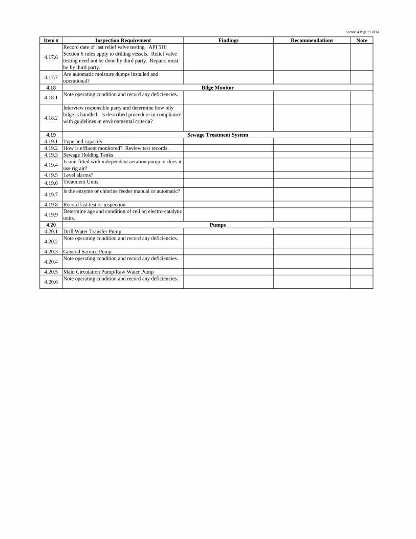
Section 4 Page 27 of 61
Item # Inspection Requirement Findings Recommendations Note
4.17.6
Record date of last relief valve testing. API 510Section 6 rules apply to drilling vessels. Relief valvetesting need not be done by third party. Repairs mustbe by third party.
4.17.7 Are automatic moisture dumps installed andoperational?
4.18
4.18.1 Note operating condition and record any deficiencies.
4.18.2
Interview responsible party and determine how oilybilge is handled. Is described procedure in compliancewith guidelines in environmental criteria?
4.194.19.1 Type and capacity.4.19.2 How is effluent monitored? Review test records.4.19.3 Sewage Holding Tanks
4.19.4 Is unit fitted with independent aeration pump or does ituse rig air?
4.19.5 Level alarms?4.19.6 Treatment Units
4.19.7 Is the enzyme or chlorine feeder manual or automatic?
4.19.8 Record last test or inspection.
4.19.9 Determine age and condition of cell on electro-catalyticunits.
4.204.20.1 Drill Water Transfer Pump
4.20.2 Note operating condition and record any deficiencies.
4.20.3 General Service Pump
4.20.4 Note operating condition and record any deficiencies.
4.20.5 Main Circulation Pump/Raw Water Pump
4.20.6 Note operating condition and record any deficiencies.
Bilge Monitor
Sewage Treatment System
Pumps

Section 5 Page 28 of 61
Item # Inspection Requirement Findings Recommendations Note
5.1
5.1.1 Conduct visual inspection of breakers, wiring andbuss works. Note deficiencies.
5.1.2
Review PM history and record last inspectioncalibration or test date for metering. Record last dateof current injection for main breakers and IR surveyof buss works.
5.1.3 Confirm installed metering and protective devices.Note deficiencies.
5.1.4 METERING5.1.5 Voltage *5.1.6 Ampere *5.1.7 KVAR5.1.8 KW5.1.9 Running Hours
5.1.10 Syncroscope5.1.11 Power Factor **
5.1.12 * = Selectable for three phase monitoring. ** =Installation is optional for parallel operation
5.1.13 PROTECTION Control voltage required to be 120volt AC or less.
5.1.14 Overload5.1.15 Short Circuit5.1.16 Reverse Power5.1.17 Under Voltage
5.1.18 Under Freq.5.1.19 Over Voltage5.1.20 Ground Fault5.1.21 Diff. Current *5.1.22 Overcurrent *
5.1.23 * = Additional devices required for greater than 600volt or 1000 KVA
5.2
5.2.1
Record insulation readings on stator and rotor andexcitation systems. Perform visual inspection andnote condition of each unit. 2 MW minimum per APIRP 14F. Test with 600 volt minimum. Include thefollowing elements in inspection:
5.2.2 RESISTANCE5.2.3 Stator5.2.4 Rotor5.2.5 Exciter5.2.6 CONDITION5.2.7 Wiring5.2.8 Bearings5.2.9 Cleanliness5.3
5.3.1 Do all AC motors have earthling straps?
5.3.2 Conduct random check of insulation resistance formotors under 15 HP. Record findings below.
5.3.3
Conduct visual inspection, operational tests andresistance check for all motors above 15 HP. Recordfindings for motors found not satisfactory. Include thefollowing elements in inspection:
5.3.4 Resistance5.3.5 Wiring
5.3.6 Vibration5.3.7 Seal leakage5.3.8 Guards and foundation.5.4
5.4.1Record insulation resistance reading of transformers.Perform visual inspection if rig is in operation.
5.4.2 Check that guards are in place and air flow isadequate.
5.4.3 Inspect metering and ground fault systems. Recordlast testing or inspection.
5.55.5.1 Do all motors have earthling straps?5.5.2 Review PM history.
5.5.3
Conduct visual inspection, operational tests andresistance checks for all DC motors. Record nonconformance findings. Include the followingelements in inspection:
5.5.4 Armature5.5.5 MW Field
DC Drive Motors
Offshore systems to be inspected for compliance with API RP 14F. Classified zone minimum compliance standard is API RP 500.
Section 5 Electrical Systems
Main and Emergency AC Generator Switchboards
Generators
AC Motors
Power Transformers

Section 5 Page 29 of 61
5.5.6 MW Comm.5.5.7 Condition of brushes & rigging5.5.8 Heaters5.5.9 Blower & filter
5.5.10 Safety devices5.6
5.6.1Perform visual inspection. Note condition of all PCboards, control transformers, air flow safety devices,starters, contactors and relays.
5.6.2Inspect metering, volt, ampere and ground detectionsystems.
5.6.3 Perform visual inspection of Buss bars and infra-redsurvey, if requested.
5.6.4 Check redundancy for all drilling equipment. Run alldrilling equipment .
5.7
5.7.1 Perform visual inspection of all breakers, motorstarters, and associated wiring.
5.7.2 Record Buss resistance to ground, if operationpermits.
5.7.3 Inspect metering and ground detection system.Record last calibration or test date.
5.7.4Review PM history. Make random checks of startercoils and contacts, local and remote start-stopstations. Note unacceptable findings.
5.8
5.8.1 Visually inspect for compliance with API RP 14F.Note any deficiencies.
5.95.9.1 Visually inspect system.5.10
5.10.1 Visually inspect all remote outlets. Confirm wire sizeof 3/0 or larger.
5.10.2 Test remote shut down system.5.11
5.11.1 Confirm lighting adequate for operations.
5.11.2 Note general condition of fixtures and check forpresence of safety cables.
5.11.3 Check for non-approved fixtures in classified zones.
5.125.12.1 Visually inspect.5.13
5.13.1 Visually inspect for proper operation of lights, remotecontrols and alarms.
5.14
5.14.1Visually inspect lighting for broken or cracked lensesand operation of flood light dimming system for nighthelicopter landings.
5.155.15.1 Confirm proper operation.5.16
5.16.1 Confirm system adequate for proper rigcommunications.
5.16.2 Check for proper operation under drilling conditions.
5.16.3 Assure system clear of electrical interference.
5.16.4 Confirm protected systems available in high noiseareas.
5.17
5.17.1 Confirm proper operation of any installed closedcircuit TV systems.
5.18
5.18.1
Test emergency power system. Simulate failure ofmain power plant. Determine if emergency plant willstart and pick up the emergency load automatically.Emergency generator should start and load within 45seconds.
5.18.2 Confirm that emergency generator can start oncompressed air and by battery power.
5.18.3Verify proper operation of meters, gauges, alarms andengine safety devices.
5.18.4 Verify that emergency power can be fed back to mainpanel.
5.18.5 Emergency power automatically supplied to followingequipment:
5.18.6 General alarm.5.18.7 Emergency lights.5.18.8 Navigation lights.
TV Systems
Emergency Generator
General Rig Lighting and Wiring
Aircraft Warning Lights
Navigation and Running Lights
Helicopter Area Lighting
Sound Powered Telephone
Rig Telephone and PA System
D.C. Generators(Not Applicable)
Main and Emergency Distribution AC Switchboards
Wireways, MCT’s, Bulkhead and Deck Penetrations
Shore Power Connection System
Welding Outlets

Section 5 Page 30 of 61
5.18.9 Bilge pump to drain each water-tight compartment.5.18.10 One fire pump.5.18.11 Fire detectors and alarms.5.18.12 Gas detectors (Combustible and H2S detectors).5.18.13 Helicopter deck lights.5.18.14 Communications.5.18.15 Electric BOP controls.5.18.16 Abandonment system.5.18.17 One air compressor5.18.18 One engine cooling pump

Section 6 Page 31 of 61
Item # Inspection Requirement Findings Recommendations Note6.16.1.1 Review all marine and vessel documentation.
Confirm compliance with vessels flag andclassification requirements.
6.26.2.1 Review manufacturer's documentation (Wire rope
certs., chain fall inspection certs., etc.)6.2.2 Review third party inspection documentation (MPI,
Underwater surveys, etc.)6.36.3.1 Confirm availability of all communications
equipment required by vessels governing authorities.Included items cover the following:
6.3.2 Distress Watch Transceiver (2182 KHZ)6.3.3 Satellite Communication System6.3.4 Single Band Radio/Radio Telephone6.3.5 VHF Radios6.3.6 Lifeboat Radio6.3.7 Walkie-Talkie Units6.3.8 Helicopter Homing Beacon (Non-Directional Beacon -
NDB)6.3.9 Satellite Navigation System6.3.10 Radio Direction Finder6.3.11 Emergency Position Indicating Radio Beacon -
(EPIRB)6.3.12 Current Meter6.3.13 Surface Monitor and Control6.3.14 Visually inspect antennas. Assure non-interference
with rig operations. Pay close attention to temporarythird party installations.
6.3.15 Verify proper operation of installed radar, GPS,LORAN, and other navigational systems.
6.46.4.1 Confirm storage areas comply with requirements
listed in section 33, Storage Rooms of OAS safetysurvey.
6.56.5.1 Confirm hydrocarbon storage complies with
requirements.6.66.6.1 Watertight doors and windows in good working
order?6.6.2 Normal ballast controls in good working order?6.6.3 Normal and emergency ballast control procedures
documented and readily available?6.6.4 Review emergency ballast control procedures.6.6.5 Review PM history as related to ballast control
systems.6.6.6 Perform visual inspection of pump rooms; observe
operation of associated equipment.6.6.7 Record date and results of last inspection by
regulatory bodies or certifying authorities.6.7 Stability6.7.1 Review source of present lightship weight and center
of gravity (CG) used in daily stability calculations, aswell as any changes to lightship since last inclining ordeadweight survey.
6.7.2 Lightship database on last inclining test is as follows:
6.7.3 Date of last inclining test or deadweight survey6.7.4 Lightship Weight in tons6.7.5 Lightship (LCG) feet aft or fwd of amidships6.7.6 Lightship (TCG) feet starboard or port of centerline6.7.7 Lightship (VCG) feet above baseline (bottom)6.7.8 The net weight of all additions and removals from
lightship weight since last inclining test is:6.7.9 Net weight (addition/removal) in tons
Ballast Control System
Section 6 Marine System
Marine Documentation
Manufacturer's and Third Party Documentation
Navigation and Communications Equipment
Storage Areas
Fuel Tanks

Section 6 Page 32 of 61
Item # Inspection Requirement Findings Recommendations Note6.7.10 Longitudinal Center (LCG) feet aft or fwd of
amidships6.7.11 Transverse Center (TCG) feet starboard or port of
centerline6.7.12 Vertical Center (VCG) feet above baseline6.7.13 Review stability and layout instructions included in
operating manual and any other stability guidelinesthat may be available. Check daily stabilitycalculations.
6.7.14 Do they include calculated displacement, anddisplacement from drafts?
6.7.15 Do they include both actual VCG (corrected for F.S.)and maximum allowable KG (for draft)?
6.7.16 Do they include a three-dimensional calculation atleast weekly?
6.86.8.1 Observe and report general condition.
6.9 Cathodic Protection (Anodes)6.10 Exhaust Stacks6.10.1 General condition?6.10.2 Condition of mufflers?6.10.3 Does age of vessel indicate possible presence of
Asbestos Containing Materials (ACM)? Pre 1984construction is presumed to have ACM unlessotherwise documented.
6.11 Hatches, Windows, Manholes, Openings andCoamings
6.11.1 Check doors and hatches for proper closing and seal.
6.11.2 Dogs and seals are present, operational,and in goodcondition?
6.11.3 Deadlights for windows are readily available, fitproperly and suit purpose?
6.11.4 Hatches, manholes, and openings are guarded whenopen?
6.11.5 Coaming drain holes or cleanout openings normallyremain closed when not in use for purpose?
6.126.12.1 Condition of grating, foundations, and handrails?6.12.2 Slip resistant material present and in acceptable
condition?6.12.3 Housekeeping?6.13 Superstructures6.13.1 General appearance?6.13.2 Note visible repairs and structual changes in
progress?6.13.3 Note last classification inspection or NDE surveys?
6.146.14.1 Confirm that Heliport and fueling facilities comply
with section 18, HELIPORT in OAS Safety Survey.6.156.15.1 Note last MPI or NDE inspection and results?6.15.2 Visually inspect for defects, cracks, or broken
members and excessive wear from wire or chain rub.
6.166.16.1 Inspect gear and procedures for heavy weather and
hurricane/typhoon evacuation.6.16.2 Deadlights for accommodation windows.6.16.3 Verify chain, wire rope, soft line, shackles, boomers,
etc. are readily available.6.16.4 Review inclimate weather and evacuation procedures
and contingency plans.6.17 Ventilation (Accommodations and Rig Area Compartments)
Hull
Walkways/Platforms
Helicopter Deck / Fueling Station
Anchor Racks
Weather Protection
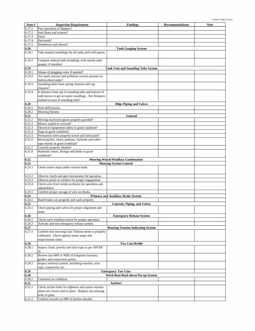
Section 6 Page 33 of 61
Item # Inspection Requirement Findings Recommendations Note6.17.1 Free operation of flappers?6.17.2 Seal floats and screens?6.17.3 Fans?6.17.4 Ductwork?6.17.5 Shutdowns and alarms?6.186.18.1 Take manual soundings for all tanks and void spaces.
6.18.2 Compare manual tank soundings with remote tankgauges, if installed.
6.196.19.1 Means of plugging vents if needed?6.19.2 Are spark arrestor and pollution screens present on
hydrocarbon tanks?6.19.3 Sounding tubes have spring closures and cap
closures?6.19.4 Is distance from top of sounding tube and bottom of
tank known to get accurate soundings. Are distancesmarked in area of sounding tube?
6.206.20.1 Note deficiencies.6.20.2 Mooring System6.216.21.1 Moving machinery/gears properly guarded?6.21.2 Motors sealed or covered?6.21.3 Electrical equipment/cables in good condition?6.21.4 Dogs in good condition?6.21.5 Permanent wires properly stored and lubricated?6.21.6 Mooring bits, cleats, padeyes, fairleads and roller-
type chocks in good condition?6.21.7 Controls properly labeled?6.21.8 Hydraulic hoses, fittings and shafts in good
condition?6.226.236.23.1 Check motor amps under various loads.
6.23.2 Observe clutch and gear movements for operation.6.23.3 Observe pawls or ratchets for proper engagement.6.23.4 Check wire level winds on drums for operation and
adjustability.6.23.5 Confirm proper storage of wire on drums.6.246.24.1 Band brakes set properly and work properly.6.256.25.1 Check piping and valves for proper alignment and
leaks.6.266.26.1 Check each windlass/winch for proper operation.6.26.2 Activate and test emergency release system.6.276.27.1 Confirm that mooring Line Tension meter is properly
calibrated. Check against motor amps andamps/tension chart.
6.286.28.1 Inspect chain, jewelry and wire rope as per API RP
2I.6.28.2 Review last MPI or NDE of fishplates brackets,
guides, and connection points.6.28.3 Inspect retrieval system, including winches, wire
rope, connectors, etc.6.296.306.30.1 Comment on condition.6.316.31.1 Check anchor bolts for tightness and assure retainer
plates are correct and in place. Replace any missingbolts or plate.
6.31.2 Confirm records on MPI of anchor shackle.
Emergency Tow LineWork Boat Back-down/Tie-up System
Anchors
Mooring System Control
Primary and Auxiliary Brake System
Controls, Piping, and Valves
Emergency Release System
Mooring Tension Indicating System
Tow Line/Bridle
Tank Gauging System
Tank Vent and Sounding Tube System
Bilge Piping and Valves
General
Mooring Winch/Windlass Combination

Section 6 Page 34 of 61
Item # Inspection Requirement Findings Recommendations Note6.31.3 Check fluke angle for operational needs.6.326.32.1 Check all fairleads for proper operation (look for
binding, not rolling, and easy swivel).6.336.33.1 Reference API RP 21 - Recommended Practice for In-
Service Inspection of Mooring Hardware for FloatingDrilling Units.
6.346.34.1 Check all rig pendants for breaks, corrosion, wear,
and proper lubrication.6.34.2 Verify that all pendant jewelry is of forged
construction.6.34.3 MPI inspect all pendant jewelry. (Could be review of
records and certs.)6.35
6.35.1 Verify that all shackles, swivels, and other jewelry areof forged construction.
6.35.2 MPI inspect all shackles, swivels and other mooringjewelry which are currently accessible.
6.366.36.1 Inspect buoys for holes, tears, deterioration that may
cause leaking.6.36.2 Determine suitability for purpose.6.36.3 Inspect buoy lights for operation and full battery
charge.6.376.37.1 Report on documentation and inspection schedule.6.37.2 Report on condition.6.386.38.1 Controls properly labeled?6.38.2 Load moment and load indicator in good condition?6.38.3 Fire extinguishers provided?6.38.4 Hand signals posted?6.38.5 Moving machinery properly guarded?6.38.6 Boom angle indicator and stops provided?6.38.7 Boom structure in good condition and free of
corrosion? Lower boom to horizontal position andline it up with a handrail or something else horizontalto check for a bent boom. Visually inspect for cracksor other boom damage.
6.38.8 "Anti-two block" device provided?6.38.9 Personnel baskets in good condition?6.38.10 Back-up safety wire required between basket and
hook?6.38.11 Drip pan provided to contain fuel/lubricant leaks?6.38.12 Review and record last load test.6.38.13 Review and record data and date on change out of
boom, load lines, and pendants.6.38.14 Wire ropes and pendants in good condition? Inspect,
measure and caliper wire as per API RP 2D. Checkfor reduction of rope diameter, broken or wornoutside wires, corroded or cracked end connections orsevere kinking or unstranding of wire.
6.38.15 Recommend to change wire rope if measuredspecifications are not acceptable.
6.38.16 Visually inspect and function sheaves, drums,clutches, brake system, gear boxes.
6.38.17 Inspect boom sheaves for free rotation, cracks andexcessive wear. Inspect shaft retainers for wear ordamage.
6.38.18 Inspect wire rope roller guides for free rotation andexcessive wear.
6.38.19 Inspect A-frame sheaves for free rotation, cracks andexcessive wear. Inspect shaft retainers for wear ordamage.
6.38.20 Are boom and pedestal flood lights operational?
Chain Link, Kenter/Connecting Links and Shackles
Buoys
Slings and Shackles
6.38 Cranes
Fairleader
Mooring Wire
Pendant Lines

Section 6 Page 35 of 61
Item # Inspection Requirement Findings Recommendations Note6.38.21 Inspect main and whip load hooks for damage and
missing locks.6.38.22 Inspect split headache ball, pin and nut for any
excessive wear or damage. Is split pin properlylocated and undamaged.
6.38.23 Verify proper operation of controls and/or remotecontrols.
6.38.24 Verify limit switches and load indicators are workingproperly.
6.38.25 Visual inspection of slip ring assembly.6.38.26 Date and details of last grease analysis.6.38.27 Start engine and check out all functions in cab, water
temp gauge, oil pressure gauge, windshield wipers,heater, horn radio and PA system.
6.38.28 Check all crane conditions with operator and ensurehe is satisfied with complete control system.
6.38.29 Can all third party equipment be mobed and demobedwith rig cranes?
6.38.30 Are all problems resolved from mechanic’s reports.
6.38.31 Remove airbox covers and inspect for worn, brokenor stuck piston rings.
6.38.32 Check injector spray pattern on piston crowns.6.38.33 Check all engine filters for leaks.6.38.34 Check airbox drain tubes with engine running.6.396.39.1 General condition?6.39.2 Properly stored when not in use?6.39.3 Life vests or jackets available for use?6.39.4 Is personnel net being used to lift materials or
supplies?6.39.5 Is safety line attached above crane ball when in use
by personnel?6.39.6 Is tag line attached and used?6.39.7 Is spare net available?6.406.40.1 Wire rope in good condition and well lubricated?6.40.2 Wire properly stored on drum?6.40.3 Date of installation and last inspection?6.40.4 Properly marked?6.40.5 Brakes adjusted properly?6.40.6 Oil levels normal and maintenance up to date?6.416.41.1 Same inspection as Air Hoist (Tuggers)6.41.2 Deadman type controls installed on tugger.6.41.3 Properly marked for man ridding?6.41.4 Good visual contact and hand signals between ridder
and man on controls?6.426.42.1 General condition and maintenance records?6.436.43.1 Visually inspect.6.43.2 Review records and documentation.6.43.3 Condition of wire rope? Well lubricated?6.43.4 Proper markings, including SWL?6.446.44.1 Visually inspect.6.44.2 Review records and documentation.6.45
6.45.1 General condition?6.45.2 Proper markings?6.466.46.1 General housekeeping at loading stations?6.46.2 Condition of hoses?6.46.3 Hoses suited for purpose and properly marked?6.46.4 Check for leaks during use? Date of last pressure
testing?
Man-Riding Tuggers
Fork Lift/Pallet Lift
Mechanical Winches
Chain Falls
Cargo Containers (Box, Net, Cargo Basket, Burn Baskets)
Hoses - Bulk Mud, Water and Oil
Billy Pugh Transfer Net (Personnel)
Air Hoist (Tuggers)

Section 6 Page 36 of 61
Item # Inspection Requirement Findings Recommendations Note6.46.5 Condition of fittings and properly fitted and secured
in hoses?6.46.6 Amount of spares and crossovers available and
condition of same.6.476.486.48.1 Perform visual inspection of living quarters, galleys,
laundry facilities.6.48.2 Perform visual inspection of heating, air
conditioning, and refrigeration systems; review PMhistory.
6.48.3 Determine square feet of office space, type of poweravailable, and number of power outlets.
6.48.4 Record condition and type of communicationequipment available.
6.48.5 Determine type and frequency of pesticides used.6.48.6 Does current program appear to be adequate?6.496.506.516.526.536.546.556.566.576.586.59
6.59.1 Confirm welding and cutting practices meetstandards outlined in section 36,Welding andBurning of OAS safety survey.
Welding and Burning Practices, Procedures and Equipment
FansDucting
Refrigeration Compressor SystemWalk-in CoolersWalk-in Freezer
Air Conditioning Pump/Brine Pump (with motor)
Quarters, Shop Furnishings and EquipmentInspection
General Accommodation Room InspectionAir Conditioning System (Main Quarters)
Galley Exhaust(s)Quarters' Ventilation System

Section 7 Page 37 of 61
Item # Inspection Requirement Findings Recommendations Note7.17.1.1 Manufacturer of cement unit?7.1.2 Verify no leaks on the liquid additive system, fill with
water if required.7.1.3 Cement pump drive unit, diesel or electric?7.1.4 Cement mixing pump (with motor)?7.1.5 Cement room controls?7.1.6 Cement recirculation mixing unit?7.1.7 Cement suction/mixing, discharge hose and piping
with valves?7.1.8 Test swivel joints (chiksans) and cement hose to MWP
and record for five (5) minutes.7.1.9 Test pumps, manifolds and valves to 250 PSI and
10,000 PSI, record for five (5) minutes each.7.1.10 Verify proper operation of chart recorders.7.27.2.1 High-pressure lines secured/anchored?7.2.2 Flare line(s) secured/staked?7.2.3 Flare lines extended minimum 150' from well; pilot
light when potential for gas exists?7.2.4 Ensure air supply for burner booms is not connected to
rig air supply.7.2.5 Is water spray system adequate?7.37.4 7.4 Burner Booms
Section 7 Third Party Equipment
Cementing System
7.2 Well Test Piping and Valves
7.3 Burners

Section 8 Page 38 of 61
Item # Inspection Requirement Findings Recommendations Note8.1
8.1.1
Is a program in place to have the system relief valvesbench tested and certified on an annual basis. (USCGrequires an annual bench test of all relief valves)
8.1.2 Record date of last inspection on APVs and reliefvalves.
8.1.3 What did the inspection consist of?8.1.4 Inspect wire rope for signs of broken strands.
8.1.5
Is a cut and slip program in place which determinesfrequency from ton-cycle exposure. Review thecumulative current ton-cycle values for compliance tothe program.
8.1.6 Note condition and length of spare tensioner wirestored on drums.
8.1.7 Visually inspect sheaves for cracks, wear andalignment.
8.1.8 Check tensioner and idler sheaves for wear with asheave groove gauge.
8.1.9 Are sheaves free and do they swivel properly?
8.1.10
Perform a system pressure test of the tensioners tomaximum anticipated system pressure + 20% or tosystem maximum rated working pressure with thetensioner cylinders fully stroked out. Inspect tensionerrods for signs of damage, peeling chrome, pitting , orindentations. Check oil levels before and after pressuretesting. This will check integrity of HP packing.
8.1.11Hold pressure for 12 hours and record pressure loss,check for leaks at gland packing area, and note locationof any air and oil leaks.
8.1.12 Note type of fluid in tensioners.8.1.13 Is there indication of oil leakage?
8.1.14 Date of last fluid samples for analysis? Record results,water content, contamination, etc.
8.1.15 Is a plan in place to determine or calculate riser tensionrequirements.
8.28.2.1 Relief valves set at 2400 psi. MWP is 2260 psi.
8.2.2
Check fluid level in high pressure accumulator bottles.With bottle bled down and relief valve removed, fromthe coupling down to the fluid level should be 35-40inches.
8.2.3
Check the fluid level in the air/oil reservoir with rodretracted into cylinder, oil level should be at lower sightglass. For proper operation of the speed limitingorifice and rod end hydraulic cushion, proper air/oilfluid levels must be maintained.
8.3
8.3.1 Relief valves set at 1900 psi. MWP is approximately1700.
8.3.2
All rod end down (RED) guide line tensioner musthave the hose in place from the end of the rod to theair/oil reservoir. This is required to purge trapped airon the low pressure side of the cylinder under thepiston.
8.4
8.4.1Confirm a program is in place to have the system reliefvalves bench tested and certified on an annual basis.
8.4.2 Record date of last relief valve inspection.
Section 8 Motion Compensating Equipment
Riser Tensioners, General
Shaffer Riser Tensioners
Guide Line, Pod/Messenger Line Tensioners
Motion Compensator, General

Section 8 Page 39 of 61
Item # Inspection Requirement Findings Recommendations Note
8.4.3
Perform a system pressure test of the compensator toMWP to confirm integrity of piping, hoses, cylindersand packing. Ensure lockbar is engaged in case of hosefailure.
8.4.4 Inspect compensator rods for signs of damage, peelingchrome, pitting , or indentations.
8.4.5 Inspect the lock bar to determine if the safety stop willprevent unintentional disengagement.
8.4.6 The lock bar lock/unlock position should be remotelyindicated on the Driller’s console.
8.4.7 Check DSC position indicator for proper operation.
8.4.8 Are the compensator hoses properly bundled andprotected to prevent snagging on the derrick.
8.4.9 Check the guide dolly for loose or missing wheels8.4.10 Check compensator wheel alignment.
8.4.11 Activate motion compensator to verify properoperation.
8.4.12 Check driller's console for leaks.
8.4.13Perform visual inspection of compensator, controlsystem high pressure air compressors, and reliefvalves.
8.4.14 Report on condition of system hydraulic pumps.
8.4.15 Verify proper operation of gauges, lock mechanism andindicator, and position indicator.
8.4.16 Sample system fluid and check for contamination.8.4.17 Are adequate spares available on board?8.4.18 Condition of deceleration valves?8.4.19 Pre-charge of deceleration accumulator?
8.5 Shaffer Compensator

Section 8 Page 40 of 61
Item # Inspection Requirement Findings Recommendations Note
8.5.1
Relief valves should be set at 2400 psi. MWP isapproximately 2260 psi. Ensure all personnel areaware of test and clear of area. Test system and hosesfor 6 hours. Since this test precludes personnelworking on rig floor. A minimum of one hour isrequired if operations will not permit a full test.
8.5.2 With at least 200 psi extending the cylinders, checkeach chain for wear and even tension.
8.5.3
Document any chain wear damage to the main frame.Review this damage with Shaffer engineering to obtaina disposition for corrective action. No welding shouldever be performed on the main frame or hook frameplates (T-6 material). Only on special situations willShaffer specify welding on a DSC plate.
8.5.4 Check that excessive chain stretch will not hinderproper operation of the lock bar.
8.5.5 Ensure lock bar spring is capable of lifting the lock barwhen load has been lifted from lock bar.
8.5.6
Check the fluid level in the air/oil reservoir. For properoperation of the cylinder speed limiting valve and rodend hydraulic cushion, proper air/oil fluid levels mustbe maintained.
8.5.7 Are there any indications of improper alignment?8.6
8.6.1 Compressors8.6.2 High Pressure APVs
High Pressure Air System

Section 9 Page 41 of 61
Item # Inspection Requirement Findings Recommendations Note9.1
9.1.1 Who is in charge of maintenance on board the rig?9.1.2 Is the maintenance function centralized or
compartmentalized? (Corporate or rig level.)9.2
9.2.1 At the rig level, do maintenance personnel haveknowledge of prior documented machinery history?
9.2.2 Do rig maintenance personnel take proactive steps toimprove machinery reliability/safety?
9.2.3 Are there any reliability indices available at the riglevel?
9.39.3.1 Are maintenance personnel actions accomplished via a
workorder system?9.4
9.4.1 Is a management information system used, eithermanual or computerized? Describe.
9.59.5.1 Are personnel adequately trained to perform expected
duties?9.5.2 Is there structured training program for skilled trades?
9.5.3 What is the overall competence level of maintenancepersonnel?
9.69.6.1 Are parts available when needed? If not, why not?9.7
9.7.1 Are maintenance tasks preventative, predictive,corrective, or inactive?
9.89.8.1 Are spare parts available as needed
Logistics Support
Maintenance Tasks / Maintenance Engineering
Spare Parts
Section 9 Maintenance System Evaluation
Management Organization and Administration
Measures of Effectiveness
Work Control
Management Information System
Personnel

Section 10 Page 42 of 61
Item # Inspection Requirement Findings Recommendations Note
10.110.1.1 OAS minimum standards are API RP 53, Third Ed.,
March 1997. Local regulatory requirements oroperator standards may exceed requirements of RP 53.
10.1.2 Minimum Testing and Maintenance guidelines can befound in API RP 53, sec. 18
10.1.3 Test flange or stump should be available for BOP wellbore pressure testing.
10.1.4 Test mandrel or drill pipe should be available for allsizes of pipe required for drilling program.
10.1.5 BOP arrangement and pressure ratings must meetOperator’s contract specifications.
10.1.6 Confirm that rig has in place a procedure to assureBOP's are tested as required; BOP drills, closingprocedures and casing pressure limit posted.
10.1.7 Confirm stack is well secured and can be alignedconveniently if required.
10.1.8 Determine if any milling operations have taken placein the past year. Date (last well)
10.1.9 Confirm full opening drill string safety valve and IBOPare available on rig floor.
10.1.10 Verify drill string safety valve handles are available inspecified locations on rig floor.
10.1.11 Confirm record of major inspection conducted forstack, choke and diverter components. API RP 53,sec. 18.10.3 recommends complete disassembly andinspection per OEM guidelines every 3-5 years.
10.210.2.1 Appropriate test pump and a four hour rotation chart
recorder should be available for testing. API RP 53,sec. 18.3.2
10.2.2 Separate low and high pressure gauges to be availablefor testing with minimum face diameter of 4.5”.Required tests to fall between 25% and 75% of gaugefull pressure range. API Spec 16A - VI B 3.2
10.2.3 Confirm all gauges in BOP control system have beencalibrated within 1% of full scale the last 3 years. APIRP 53, sec. 13.9.3g
10.2.4 Acceptance criteria is a straight line pressure test withno test fluid leakage. No leaks is minimum standardfor all pressure testing.
10.2.5 Fluorescein dye should be added to fluid prior tocommencement of testing.
10.2.6 Operating chambers to be tested to maximum ratedworking pressure for 5 minutes with possible exceptionof annular open/close operating chambers. (Note: Donot exceed 1500 PSI on Shaffer Annulars.)
10.2.7 Review testing procedures confirming the followingpoints are addressed:
10.2.8 · Low pressure testing, 200-300 PSI, with aminimum duration of 5 minutes is to be performedbefore high pressure testing. API RP-53, sec. 18.3.2.1
10.2.9 · High pressure testing is to be held stable for 10minutes. API RP 53, sec. 18.3.2.2. (Chevronrequirement)
10.2.10 · Intervals between BOP pressure and function testsshould be per government requirements or operatorrequirements, whichever is stricter.
Any time testing and inspection deviates from this procedure for any reason, confirm suitability with Operator’s representative andrecord reason on daily report and trip report.
Section 10 Subsea Blowout Prevention Equipment
General Requirements
Pressure Testing

Section 10 Page 43 of 61
Item # Inspection Requirement Findings Recommendations Note10.2.11 Maximum interval for function testing should not
exceed one week. Function testing should bealternated from drillers to remote panels. API RP 53,sec. 18.3.1. (UK and Chevron requirements willsupercede)
10.2.12 Pressure testing should be conducted prior to spud,after change of any BOP element or at an interval notto exceed 21 days. API RP 53, sec. 18.3.3 (UK andChevron requirements will supercede)
10.2.13 · Ram locking devices should be operated andoperation demonstrated while pressure testing per apreset schedule. (Rams closed, locks engaged,operating pressure bled off, perform wellbore test.)API RP 53, sec. 17.5.8
10.2.14 · Annular preventers and multiple size rams shouldbe tested on all sizes of pipe to be used on well.Preventers should be operated with standard operatingpressure while testing.
10.2.15 · Valves shall be tested from direction in which theyshall see pressure in service, such as kill lines andvalves between buffer chambers and chokes.
10.2.16 · Each piece of equipment undergoing test should berecorded on the test chart.
10.2.17 · Problems and corrective actions should berecorded either on the chart or on a separate document.
10.3.110.3.1.1 Check throughbore for keyseating damage and record
findings.10.3.1.2 Check vent ports and bodies for signs of hydraulic
fluid or wellbore fluid leakage.10.3.1.3 Check preventer exterior for signs of hydraulic or
wellbore fluid leakage.10.3.1.4 Check ram cavities for the following: (if possible have
bonnets/doors opened prior to arrival of audit team)
10.3.1.5 · Ram change rods, ram shaft sealing surfaces, &bonnet sealing surfaces shall be in good condition.
10.3.1.6 · Ram shaft packing retainer shall be in position.Check for excessive corrosion in the area of retainerring groove.
10.3.1.7 · Ram blocks shall be checked for damage causedby closing on tool joints
10.3.1.8 · Check P/N to verify H2S service ram blocks are inuse if required by operator..
10.3.1.9 · Confirm ram elastomers are in excellent condition.Elastomers on BOP’s which have been out of servicemore than 6 months should be considered forreplacement. API RP 53, sec. 18.5.11
10.3.1.10 Conduct a hydraulic operating chamber pressure test tomaximum working pressure. Pressure to workingpressure of operator and held for 5 minutes whilerecorded on chart.
10.3.1.11 Perform well bore pressure test at 250 psi and toMWP.
10.3.1.12 Confirm integrity of ram locking system during wellbore tests.
10.3.1.13 Confirm ability of shear rams to cut drill pipe to beused. Reference information from the appropriatemanufacturer’s engineering bulletin. Note thatdevelopments in quality of tubulars has left someshearing systems unable to cut pipe. Use of specialram blocks, large bore or tandem boosters may berequired for some operations.
10.3.1.14 Confirm spare ram blocks are suitable for intendeddrilling program.
Ram #1

Section 10 Page 44 of 61
Item # Inspection Requirement Findings Recommendations Note10.3.2 Ram #210.3.2.1 Check through-bore for key-seating damage and record
findings.10.3.2.2 .Verify ram preventers have adequate clearance for
tool joints between pipe rams to allow ram to ramstripping.10.3.2.3 Check vent ports and bodies for signs of hydraulicfluid or well-bore fluid leakage.
10.3.2.4 Check preventer exterior for signs of hydraulic or well-bore fluid leakage.
10.3.2.5 Check ram cavities for the following: (if possible havebonnets/doors opened prior to arrival of audit team)
10.3.2.6 · Ram change rods, ram shaft sealing surfaces, &bonnet sealing surfaces shall be in good condition.
10.3.2.7 · Ram shaft packing retainer shall be in position.Check for excessive corrosion in the area of retainerring groove.
10.3.2.8 · Ram blocks shall be checked for damage causedby closing on tool joints
10.3.2.9 Check P/N to verify H2S service ram blocks are in useif required by operator.
10.3.2.10 · Confirm ram elastomers are in excellent condition.Elastomers on BOP’s which have been out of servicemore than 6 months should be considered forreplacement. API RP 53, sec. 18.5.11
10.3.2.11 Conduct a hydraulic operating chamber pressure test tomaximum working pressure.
10.3.2.12 Perform well bore pressure test at 250 psi and toMWP.
10.3.2.13 Confirm integrity of ram locking system during wellbore tests.
10.3.2.14 Ram cavity specified for drill pipe hang off shall beequipped with hang-off ram blocks. Verifymanufacturer’s P/N. State capacity.
10.3.2.15 Confirm spare ram blocks are suitable for intendeddrilling program.
10.3.310.3.3.1 Check through-bore for key-seating damage and record
findings.10.3.3.2 Verify ram preventers have adequate clearance for tool
joints between pipe rams to allow ram to ram stripping.
10.3.3.3 Check vent ports and bodies for signs of hydraulicfluid or well-bore fluid leakage.
10.3.3.4 Check preventer exterior for signs of hydraulic or well-bore fluid leakage.
10.3.3.5 Check ram cavities for the following: (if possible havebonnets/doors opened prior to arrival of audit team)
10.3.3.6 · Ram change rods, ram shaft sealing surfaces, &bonnet sealing surfaces shall be in good condition.
10.3.3.7 · Ram shaft packing retainer shall be in position.Check for excessive corrosion in the area of retainerring groove.
10.3.3.8 · Ram blocks shall be checked for damage causedby closing on tool joints
10.3.3.9 · Check P/N to verify H2S service ram blocks are inuse if required by operator.
10.3.3.10 · Confirm ram elastomers are in excellent condition.Elastomers on BOP’s which have been out of servicemore than 6 months should be considered forreplacement. API RP 53, sec. 18.5.11
10.3.3.11 Conduct a hydraulic operating chamber pressure test tomaximum working pressure on open and close side.
Ram #3
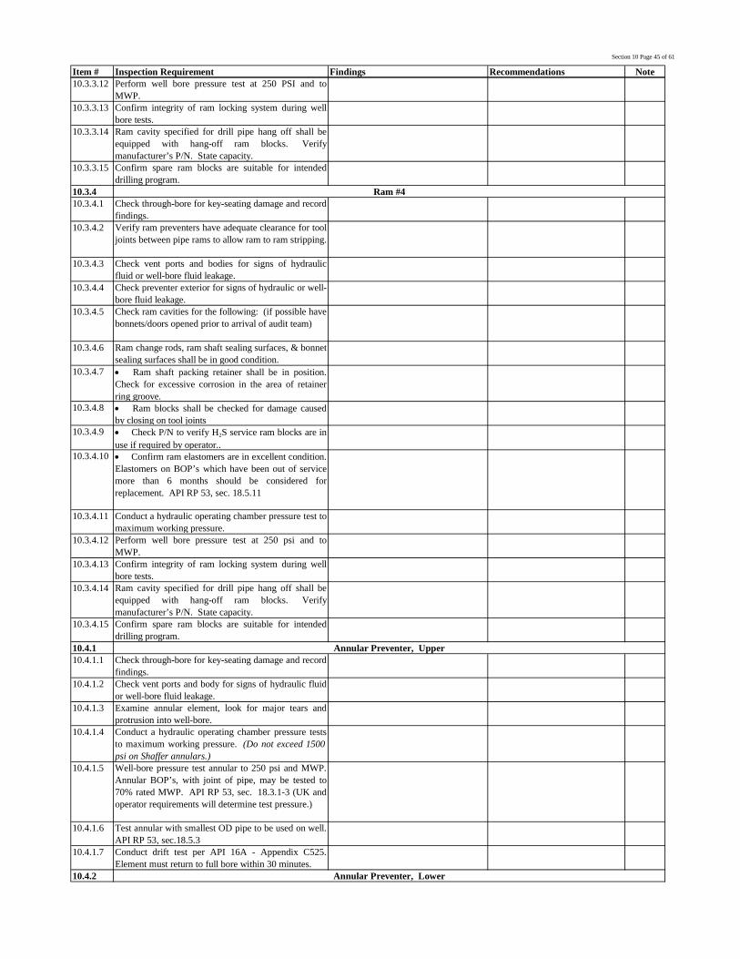
Section 10 Page 45 of 61
Item # Inspection Requirement Findings Recommendations Note10.3.3.12 Perform well bore pressure test at 250 PSI and to
MWP.10.3.3.13 Confirm integrity of ram locking system during well
bore tests.10.3.3.14 Ram cavity specified for drill pipe hang off shall be
equipped with hang-off ram blocks. Verifymanufacturer’s P/N. State capacity.
10.3.3.15 Confirm spare ram blocks are suitable for intendeddrilling program.
10.3.410.3.4.1 Check through-bore for key-seating damage and record
findings.10.3.4.2 Verify ram preventers have adequate clearance for tool
joints between pipe rams to allow ram to ram stripping.
10.3.4.3 Check vent ports and bodies for signs of hydraulicfluid or well-bore fluid leakage.
10.3.4.4 Check preventer exterior for signs of hydraulic or well-bore fluid leakage.
10.3.4.5 Check ram cavities for the following: (if possible havebonnets/doors opened prior to arrival of audit team)
10.3.4.6 Ram change rods, ram shaft sealing surfaces, & bonnetsealing surfaces shall be in good condition.
10.3.4.7 · Ram shaft packing retainer shall be in position.Check for excessive corrosion in the area of retainerring groove.
10.3.4.8 · Ram blocks shall be checked for damage causedby closing on tool joints
10.3.4.9 · Check P/N to verify H2S service ram blocks are inuse if required by operator..
10.3.4.10 · Confirm ram elastomers are in excellent condition.Elastomers on BOP’s which have been out of servicemore than 6 months should be considered forreplacement. API RP 53, sec. 18.5.11
10.3.4.11 Conduct a hydraulic operating chamber pressure test tomaximum working pressure.
10.3.4.12 Perform well bore pressure test at 250 psi and toMWP.
10.3.4.13 Confirm integrity of ram locking system during wellbore tests.
10.3.4.14 Ram cavity specified for drill pipe hang off shall beequipped with hang-off ram blocks. Verifymanufacturer’s P/N. State capacity.
10.3.4.15 Confirm spare ram blocks are suitable for intendeddrilling program.
10.4.110.4.1.1 Check through-bore for key-seating damage and record
findings.10.4.1.2 Check vent ports and body for signs of hydraulic fluid
or well-bore fluid leakage.10.4.1.3 Examine annular element, look for major tears and
protrusion into well-bore.10.4.1.4 Conduct a hydraulic operating chamber pressure tests
to maximum working pressure. (Do not exceed 1500psi on Shaffer annulars.)
10.4.1.5 Well-bore pressure test annular to 250 psi and MWP.Annular BOP’s, with joint of pipe, may be tested to70% rated MWP. API RP 53, sec. 18.3.1-3 (UK andoperator requirements will determine test pressure.)
10.4.1.6 Test annular with smallest OD pipe to be used on well.API RP 53, sec.18.5.3
10.4.1.7 Conduct drift test per API 16A - Appendix C525.Element must return to full bore within 30 minutes.
10.4.2
Ram #4
Annular Preventer, Upper
Annular Preventer, Lower

Section 10 Page 46 of 61
Item # Inspection Requirement Findings Recommendations Note10.4.2.1 Check through-bore for key-seating damage and record
findings.10.4.2.2 Check vent ports and body for signs of hydraulic fluid
or well-bore fluid leakage.10.4.2.3 Examine annular element, look for major tears and
protrusion into well-bore.10.4.2.4 Conduct a hydraulic operating chamber pressure tests
to maximum working pressure. (Do not exceed 1500psi on Shaffer annular)
10.4.2.5 Test annular with smallest OD pipe to be used on well.API RP 53, sec.18.5.3
10.4.2.6 Conduct drift test per API 16A - Appendix C525.Element must return to full bore within 30 minutes.
10.510.5.1 Target flanges shall be removed for verification of lead
content and erosion.10.5.2 Subsea valves shall be hydraulically pumped opened
and allowed to close with spring force alone to verifyproper operation of the assist-close system. (If aseparate hydraulic close assist system exists theoperation will be verified.)
10.5.3 Pressure test valves from the top prior to BOP goingsubsea.
10.5.4 Pressure test operating chambers to MWP.10.5.5 Pressure test valves to 250 PSI and MWP.10.610.6.1 To what standard, API, contractor, or operator, is the
accumulator unit sized?10.6.2 Conduct an accumulator volume test according to API
RP-53, 3rd edition, section 13.3.2 and 18.7.1 Theaccumulator bottles shall be able to deliver, with thepumps turned off, enough usable fluid to close andopen all ram preventers and one annular preventer.
10.6.3 The combination of all pump systems should becapable of charging the accumulator system from theminimum calculated operating pressure to the systemmaximum rated pressure in 15 minutes. API RP 53section 13.4.1
10.6.4 Confirm surface accumulator precharge is 1000 psi for3000 psi systems. API RP 53,sec. 13.3.7
10.6.5 Open reservoir inspection ports and confirm properfluid level and that no bacteria or contamination is inthe fluid.
10.6.6 Perform random fluid check to a few pod pilot lines oneach pod. They are susceptible to bacteria growth.Bacteria in lines will eventually cause excessivecorrosion, damage in pod valve components, and podvalve failure.
10.6.7 Does the rig have a fluid condition monitoringprogram? Are fluid strainers cleaned on a schedule?Confirm fluid meets requirements of API RP 53, sec.13.3.9
10.6.8 Record for corrective action any functions, regulators,or relief valves leaking fluid into the reservoir.
10.6.9 Determine if hydraulic power unit has two powersources to recharge accumulator bottles in the eventone should fail. API RP 53, sec. 13.4.1
10.6.10 Verify accumulator bottle isolation valves are in theopen position.
10.6.11 Does rig implement safe work permit or isolationpermit system when working on HP accumulators?
10.6.12 Are all hydraulic power unit and remote panelfunctions and gauges clearly labeled? API RP 53, sec.13.9.3 f
BOP Stack Mounted Valves
BOP Control Unit and Remote Panels

Section 10 Page 47 of 61
Item # Inspection Requirement Findings Recommendations Note10.6.13 Confirm controls for shear rams have a cover to
prevent accidental operation. Cover shall not belocked. API RP 53, sec. 13.9.3 f
10.6.14 Operate all functions and regulators from remotepanels and at main unit.
10.6.15 Pressure test the control system:10.6.16 Place control system in drilling position and apply full
system pressure to the unit, rig piping, hoses, andpreventers. ( 1,500 psi max. Shaffer annulars)
10.6.17 · Repeat pressure test with preventers in the closedor killing position.
10.6.18 Are accumulator unit and controls safe distance fromrig floor.? API RP 53, sec. 13.5.1
10.6.19 Are rig personnel trained on operation of BOPcontrols? What type of well control certification, andis certification up to date?
10.6.20 Check the control system for external leaks at pipefittings, hoses and couplings.
10.6.21 Check subsea, surface and pilot accumulator bottles,plus annular surge bottles for correct precharge per thewater depth.
10.6.22 Check surface and subsea accumulator bottles forproper N2 precharge per water depth, including allpilot, failsafe and annular surge bottles whereapplicable.
10.6.23 Control system pods shall latch and unlatch properly.No obstructions shall be above the pod to prevent theirretrieval.
10.6.24 Check that control system regulators have been up-graded to allow operation with the loss of rig airsupply.
10.6.25 Any newly assembled control system hoses shall bepressure tested to 1.5 x WP prior to installation.
10.6.26 All critical hoses (e.g. shear ram close, connectorunlock) shall be pressure tested to 1.25 x WP.
10.6.27 All functions, gauges and regulators shall operateproperly from the remote panels and the hose reelpanels.
10.6.28 Record the gallon count and time required for eachfunction from both pods.
10.6.29 Function response times shall meet API RP-53, 3rdedition, section 13.3.5. Rams shall close within 45seconds and annulars shall close within 60 seconds.
10.6.30 Pressure test the complete control system at full systempressure of 3,000 psi for 20 minutes, lining up eachpod in both the drilling position and the killingposition. (only 1,500 psi on Shaffer annulars)
10.6.31 Review the current ROV capabilities for correctinstallation and propose changes or additions ifrequired. Operate the ROV functions.
10.710.7.1 Choke and kill hoses adequately sized; properly
secured?10.7.2 Examine armor for signs of physical damage. Conduct
visual inspection per API RP 53, sec. 18.10.210.7.3 Have C/K lines been pressure tested as required?
Testing required same as BOP’s API RP 53 , sec.18.10.2
10.7.4 Review records of HP hose tests.10.7.5 · HP choke, kill, and cement hoses shall be
inspected and tested per manufacturer’srecommendations. Appropriate equipment manualsshould be available at each rig.
Choke and Kill Hoses

Section 10 Page 48 of 61
Item # Inspection Requirement Findings Recommendations Note10.7.6 Record manufacturer, serial number, WP and date of
manufacture on all choke and kill flexible hoses. Thisinformation is lettered on the ends of the hose.
10.810.8.1 Confirm choke manifold meets operator contract
specifications.10.8.2 Confirm choke manifold meets API RP 53, sec. 8.2.
10.8.3 Components subjected to well bore pressure should beflanged, clamped or welded. API RP 53 3,sec. 8.2.b
10.8.4 Open and inspect targets for erosion or lead content asfollows:
10.8.5 1. Targets in manifold T
10.8.6 2. Targets in C/K lines between manifold and droop hoses.
10.8.7 3. Targets on BOP
10.8.8 Confirm proper calibration of manifold and drill pipewell control pressure gauges.
10.8.9 Confirm that a fill-up line separate from the kill line isavailable.
10.8.10 Choke and kill lines plus manifolds should be securedand all 90o bends targeted.
10.8.11 Is choke line diameter and pressure rating adequate forthe intended operation?
10.8.12 Confirm availability of adequate spares per API RP 53,sec. 8.5
10.8.13 Check that choke lines are manifolded so fluids can be:
10.8.14 · Dumped overboard10.8.15 · Degassed and mud recovered10.8.16 Check valve hand wheels for free operation.10.8.17 Review rig’s schedule for valve greasing. Do valves
appear to have been greased per schedule? Confirmuse of OEM recommended lubricant.
10.8.18 Perform low pressure testing to 250 PSI /5 minutes andhigh pressure testing / 10 minutes to MWP.
10.8.19 Visually inspect interior of mud/gas separator forcorrosion. Refer to API RP 53, sec. 16.9
10.8.20 Sketch mud/gas separator, note height of mud seal.10.8.21 Is separator of adequate volume, vent line of proper
diameter and mud seal of adequate height for theoperation?
10.8.22 Measure gas vent line ID. Is height adequate for safeoperation?
10.910.9.1 Verify proper operation and record any deficiencies.
API RP 53, sec. 18.6.310.9.2 Manual and hydraulic chokes shall be opened to check
for erosion or damage10.9.3 Adjustable chokes do not require full sealing. API RP
53 3rd ED sec. 18.6.410.9.4 Confirm manual choke position indicator is readable
and remote choke position indicator is functioning andproperly calibrated.
10.1010.10.1 Verify proper operation and record any deficiencies.
API RP 53, sec. 18.6.310.10.2 Chokes shall be opened to check for erosion or
damage. Pressure test chokes to confirm they areworking properly.
10.10.3 Adjustable chokes do not require full sealing. API RP53, sec. 18.6.4
10.10.4 Verify operation of remote choke panel pump strokecounter.
10.10.5 Verify operation of alternate power supply for theremote choke.
10.11
Choke Manifold
Manual Choke
Remote Choke and Controls
Diverter System

Section 10 Page 49 of 61
Item # Inspection Requirement Findings Recommendations Note10.11.1 Function test the diverter packer and both insert and
diverter assembly lockdown dogs, checking for signsof leakage.
10.11.2 Examine the flow line seals for damage. Replaceseverely seals.
10.11.3 Pressure test ball joint seals with grease gun and apressure gauge. Diverter systems are typically tested tolow pressure only after they are installed. (200 psitypical because the slip joint seal is the limiting factor.)API RP 53, sec.18.4.1d
10.11.4 Inspect and test insert packer lock down dogs.Confirm alignment pins are properly installed.
10.11.5 Confirm vent line valves are full-opening type anddesigned to automatically open before diverter closes.Per API RP 53, Section 5.2.3
10.11.6 Function test diveter system and any interlock(s).Refer to API RP 53, sec. 18.4.1-2
10.11.7 If system cannot be function tested document why.10.1210.12.1 Confirm all studs are B7 and nuts are 2H.10.12.2 Review rig bolt pre-loading procedures and lubricant.
API RP 53, sec. 18.11.2 and 18.11.4, API Spec. 6AAny wellbore pressure connection should be re-torquedafter a full pressure test.
10.12.3 Confirm face to face contact for assembled AX, BXand CX flanges and hubs. Disassemble and faultdetermination is required for properly torquedconnections failing to make face to face contact.
10.1310.13.1 Examine all grooves for signs of damage.10.13.2 Assure no resilient gaskets are in use or available on
rig. API RP 53, sections 18.11.210.1410.14.1 Connectors shall have a flag on the position indicator
which can be observed by the rig camera and the ROVcamera.
10.14.2 Connectors shall be lubricated with the lubricantspecified by the manufacturer.
10.14.3 Gasket retainer pins shall function properly.10.14.4 If the wellhead connector has a POCV check valve
installed in the lock hydraulic line, function andpressure test.
10.14.5 Unlatch the connectors checking that the requiredunlatching pressures are within the limits specified bythe manufacturer.
10.14.6 Record required primary or secondary unlockingpressure after closing with 1,500 psi or 3,000 psiclosing pressure. Consult Vetco’s OSP #335 forallowable unlocking pressures.
10.14.7 Actions shall be taken to correct connector operation.
10.1510.15.1 Visually inspect each riser box and pin. Check
condition of riser locking mechanism. Surface finishof pins shall be acceptable. If pins have been skim cut,adequate diameter shall be verified with originalmanufacturer.
10.15.2 Inspect riser buoyancy and attachment straps. Reportdamage and inadequate attachment.
10.15.3 Riser seals shall be in as new condition. Adequatechoke and kill line seals shall be on board to replace allseals for the anticipated water depth.
10.15.4 Check that choke and kill lines end float is per themanufacture’s recommendation.
10.15.5 Check to insure all riser choke and kill line clamps areproperly bolted and in good condition.
Connectors
Riser
Clamps, Flanges and Fasteners
Ring Gaskets and Grooves

Section 10 Page 50 of 61
Item # Inspection Requirement Findings Recommendations Note10.15.6 Review the riser NDE procedures. All used riser end
connections and butt welds are to be MPI inspected toa correct procedure.
10.15.7 Date and results of last wall thickness survey C & Klines?
10.15.8 Riser Joint NDE/wall thickness10.15.9 Riser Spider NDE10.15.10 Riser Handling Tools NDE10.15.11 Elevator and Bales NDE10.15.12 500 ton elevators and bales are recommended for stack
handling.10.1610.16.1 Telescopic joint NDE / wall thickness?10.16.2 Review NDE procedures. All end connections and
butt welds are to be subjected to NDE after every 180service days.
10.16.3 Date and results of last wall thickness survey Surveysshould be conducted every 5 years.
10.1710.17.1 Details of NDE and record wall thickness.10.17.2 Check through bore for key-seating and record
findings.10.1810.18.1 Check through bore for key-seating and record
findings.10.18.2 Ensure that condition of lower to upper body studs are
satisfactory and torqued to manufacturer’s specs. Thispertains to both ball and flex joints.
10.1910.19.1 Rig positioning system shall be properly calibrated by
a person competent in its operation.10.2010.20.1 Review current ROV capabilities and for correct
installation. Propose changes or additions as required.
10.2110.21.1 Comment on condition of the BOP handling system.10.21.2 Record date system was inspected by qualified
personnel.10.21.3 Do cables appear in good condition?10.21.4 Record in service date of cables.10.2210.22.1 Confirm well control equipment and associated
operations comply with local regulatory requirements.
10.22.2 Intervals between tests should be per governmentrequirements or operator requirements, whichever isstricter.
10.22.3 Maximum interval for function testing should notexceed one week. Function testing should be alternatedfrom driller's to remote panels. API RP 53, sec. 18.3.1.
10.22.4 Pressure testing should be conducted prior to spud, afterchange of any BOP element or at an interval not toexceed 21 days. API RP 53, sec. 18.3.3
10.22.5 Confirm that rig has in place a procedure to assure BOPsare tested as required; BOP drills, closing procedures,casing pressure limit posted and emergency riser unlatchprocedures
10.22.6 Confirm record of major inspection conducted forstack, choke and diverter components. API RP 53, sec.18.10.3 recommends complete disassembly andinspection per OEM guidelines every 3-5 years.
10.22.7 Are rig personnel current on required well controltraining?
10.2310.23.1 Is current file available containing OEM (original
equipment manufacturer) safety and repair notices forinstalled equipment. API RP 53, sec. 18.12.2
ROV
BOP Handling System
Rig Floor, Procedures and Regulatory
Bulletins
Telescopic Joint
Riser Adapter
Ball Joint
Rig Positioning Equipment

Section 10 Page 51 of 61
Item # Inspection Requirement Findings Recommendations Note10.23.2 Have all OEM recommendations and modifications
been implemented?10.2410.24.1 Review rig PM system. Are well control equipment
items included and maintained as required? API RP53, sec.18.12.1
10.24.2 Are repair and maintenance records accurate and up todate?
10.24.3 Is a history file maintained per API RP 53,sec.18.13.2?
10.24.4 Confirm adequate BOP spare parts are on board. APIRP 53, sec. 7.6, 9.4, 11.5
10.24.5 Are API documents (spec 6A, 16A, 16C, 16D, RP 53,16Q, 64) available as recommended? Reference APIRP 53, sec.18.13.5
10.24.6 Is stored BOP equipment maintained according toguidelines in API RP 53, Sec.18.11.5?
10.2510.25.1 Inspect well-bore pressure containing components for
signs of unauthorized welding. Weld repairs can beperformed only in compliance with guidelinesreferenced in API RP 53, sec.18.11.7
10.25.2 Examine all components for evidence of unauthorizedweld repairs. Examine rig high pressure lines forpatches.
Preventative Maintenance
Welding

Section 11 Page 52 of 61
Item # Inspection Requirement Findings Recommendations Note11.111.1.1 Check “Hazardous Area Enclosure Register” and
ensure annual inspection is being carried out.11.1.2 Safety equipment available and worn?11.1.3 Appropriate warning and safety signs displayed?11.1.4 Qualified first-aider on each crew?11.1.5 First-aid supplies.11.1.6 Emergency eyewash station.
11.1.7 Emergency phone numbers posted?11.1.8 Welding/cutting procedures as required.11.1.9 Lockout/Tagout procedures as required.11.1.10 Designated smoking areas with matches, lighters and
materials controlled?11.211.2.1 Hard hats and steel-toed boots/shoes worn?11.2.2 Eye protection.11.2.3 Gloves.11.2.4 Protective clothing.11.2.5 Hearing protection.11.2.6 Respiratory protection.11.2.7 Belts and safety lines.11.311.411.5 Yes11.5.1 Clear, easy access provided?
11.5.2 Craft labeled per regulation?11.5.3 Maintained in working order?11.5.4 Start engine.11.5.5 Test emergency start.11.5.6 Test VHF radio.11.5.7 Lower boat.11.5.8 Launch/Release hook.11.5.9 Test sprinkler system.11.5.10 Test bilge pump.11.5.11 Is EPIRB included? (IMO 11.4.1.3)11.5.12 Check engine operation.11.5.13 Raise boat.
11.5.14 Does boat stop before striking platform?11.5.15 Is hoisting mechanism and cable in good condition?
Falls used in launching shall be turned end for end atintervals of not more than 30 months and be renewedwhen necessary due to deterioration of falls or atintervals of not more than 5 years, whichever is earlier.(SOLAS Chapter III 19.4),
11.5.16 If falls cannot be turned end for end, then they must bereplaced every 4 years. (IMO MODU Code 10.18.4)
11.5.17 Are provisions adequate?11.5.18 Regularly inspected and tested?11.5.19 Record date of last inspection.11.5.20 Record personnel capacity.11.5.21 Record overall condition.11.611.6.1 Manufacturer.11.6.2 Type/model.11.6.3 Quantity.11.6.4 Size.11.6.5 Record date of last inspection.11.6.6 Is a spare available to use during servicing?
Section 11 Safety Survey
General Requirements
Personal Protective Equipment
HospitalLifesaving EquipmentLifeboats
Life Rafts

Section 11 Page 53 of 61
Item # Inspection Requirement Findings Recommendations Note11.6.7 Record condition of raising and lowering system.11.6.8 Inflatable life rafts - stored in good condition?11.6.9 Inspected annually?11.6.10 Instructions posted?11.6.11 Launching mechanism in good condition?11.711.7.1 Fast Rescue Craft per regulation?
11.7.2 Launch, operate, and retrieve rescue boat.11.7.3 Record date of last inspection.
11.7.4 Record any deficiencies.11.811.8.1 List manufacturer, date and model.11.8.2 Check total quantity on board.11.8.3 Check condition.11.8.4 Check quantities at each stowage location.11.8.5 Coverage of life preservers per regulation?11.8.6 Properly stored?11.8.7 Approved?11.8.8 Labeled?11.8.9 Whistles?11.8.10 Lights and reflective tape?11.8.11 Immersion suits per regulation? Quantity?11.8.12 Work vests provided and used for work over water?
11.8.13 Ring life-buoys - proper number, position properlyequipped?
11.911.9.1 Compressor:11.9.2 Inspect hoses for chaffing or excessive wear damage.
11.9.3 Condition and tension of drive belts.11.9.4 Condition of cable and plug for cuts, flattened or
pinched sections.11.9.5 Record date of last air filter change.11.9.6 Run compressor on test for several minutes.11.9.711.9.8 Inspect mask and hose contamination, damage or
corrosion.11.9.9 When were cylinders sent off rig for
inspection/recertification.11.9.10 Check cylinder gauge for damage.11.9.11 Check cylinder pressure.11.9.12 Examine harness for excessive wear or damage.11.9.1311.9.14 Are SCBAs located outside areas with automatic fire
suppression systems?11.1011.10.1 Are at least two (2) fire pumps installed?11.10.2 Insure that pumps are isolated from each other.11.10.3 Test each fire pump for adequate output pressure and
record. Check for vibration and overheating. Checkmechanical seal for leakage. Record date of last majoroverhaul.
11.10.4 Test installed helideck foam monitor.11.10.5 Test water cannons.11.10.6 Test rig floor and cellar deck deluge system.11.10.7 Is accommodation sprinkler system operational? Is
maintenance being carried out as per PM system?Check operating pressure at sprinkler tank. Record anydrop from set pressure.
11.10.8 Does a fire pump run from emergency generatorboard?
11.1111.11.1 Inspect each fire station (fire main) for readiness and
condition.
Life Preservers and Life Rings
Self-Contained Breathing Apparatus
Fire Pumps
Fire Fighting Equipment
Rescue Boat
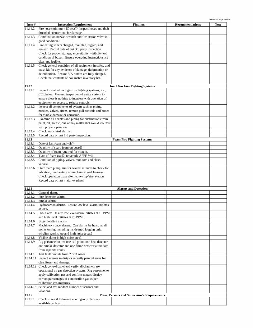
Section 11 Page 54 of 61
Item # Inspection Requirement Findings Recommendations Note11.11.2 Fire hose (minimum 50 feet)? Inspect hoses and their
threaded connections for damage.11.11.3 Combination nozzle, wrench and fire station valve in
good condition?11.11.4 Fire extinguishers charged, mounted, tagged, and
sealed? Record date of last 3rd party inspection.Check for proper storage, accessibility, visibility andcondition of boxes. Ensure operating instructions areclear and legible.
11.11.5 Check general condition of all equipment in safety andcrash kit for any evidence of damage, deformation ordeterioration. Ensure B/A bottles are fully charged.Check that contents of box match inventory list.
11.1211.12.1 Inspect installed inert gas fire fighting systems, i.e.,
C02, halon. General inspection of entire system toensure there is nothing to interfere with operation ofequipment or access to release controls.
11.12.2 Inspect all components of system such as piping,nozzles, valves, sirens, remote pull controls and boxesfor visible damage or corrosion.
11.12.3 Examine all nozzles and piping for obstructions frompaint, oil, grease, dirt or any matter that would interferewith proper operation.
11.12.4 Check associated alarms.11.12.5 Record date of last 3rd party inspection.11.1311.13.1 Date of last foam analysis?11.13.2 Quantity of spare foam on board?11.13.3 Quantity of foam required for system.11.13.4 Type of foam used? (example AFFF 3%)11.13.5 Condition of piping, valves, monitors and check
valves?11.13.6 Start foam pump, run for several minutes to check for
vibration, overheating or mechanical seal leakage.Check operation from alternative stop/start station.Record date of last major overhaul.
11.1411.14.1 General alarm.11.14.2 Fire detection alarm.11.14.3 Smoke alarm.11.14.4 Hydrocarbon alarms. Ensure low level alarm initiates
at 20%.11.14.5 H2S alarm. Insure low level alarm initiates at 10 PPM,
and high level initiates at 20 PPM.11.14.6 Bilge flooding alarms.11.14.7 Machinery space alarms. Can alarms be heard at all
points on rig, including inside mud logging unit,wireline work shop and high noise areas?
11.14.8 Visible alarm in high noise area?11.14.9 Rig personnel to test one call point, one heat detector,
one smoke detector and one flame detector at randomfrom separate zones.
11.14.10 Test fault circuits from 2 or 3 zones.11.14.11 Inspect sensors in dirty or recently painted areas for
cleanliness and damage.11.14.12 Check control panel and verify all channels are
operational on gas detection system. Rig personnel toapply calibration gas and confirm meters displaycorrect percentages of combustible gas as percalibration gas mixtures.
11.14.13 Select and test random number of sensors andlocations.
11.1511.15.1 Check to see if following contingency plans are
available on board.
Inert Gas Fire Fighting Systems
Foam Fire Fighting Systems
Alarms and Detection
Plans, Permits and Supervisor's Requirements

Section 11 Page 55 of 61
Item # Inspection Requirement Findings Recommendations Note11.15.2 Man overboard.11.15.3 Fire.11.15.4 Abandon rig.11.15.5 Critical H2S wells (sour gas).11.15.6 Current well control training?11.15.7 Confined Space Entry procedures as required.11.15.8 Incident report forms.11.15.9 Procedure for reporting accidents.11.15.10 Accident/injury forms filled out & copies to Operator's
Supervisor?11.15.11 Drilling Safety Program Manual.11.1611.16.1 Are fire drills conducted weekly?11.16.2 Are abandonment drills conducted weekly?11.16.3 Review / critique drills.11.16.4 Drills follow IADC guidelines?11.16.5 Check records of drills.11.1711.17.1 Regular safety inspections performed and corrections
made; records on-site?11.17.2 Accident prevention program in effect?11.17.3 Safety meetings held regularly? Safety meeting
minutes on record?11.17.4 Personnel training (API RP-54, well control, H2S;
FA/CPR, fire) records available?11.17.5 Employees trained in safety policies; orientation given
to all new employees?
Records
Drills

Section 11 Page 56 of 61
Item # Inspection Requirement Findings Recommendations Note11.17.6 Local doctor and hospital telephone numbers posted by
phone in tool pusher's office?11.17.7 Maintenance program and records for critical
equipment?11.1811.18.1 Depending on expected H2S concentration,
government regulation and management direction, is acopy of appropriate H2S regulations available?
11.18.2 Contingency plan on location, if required?11.18.3 Annual H2S safety training of personnel?11.18.4 First-aid training for H2S exposure provided in
employee training?11.18.5 Materials and equipment selected for H2S service?11.18.6 Protective breathing equipment maintained at two (2)
places on well site?11.18.7 Two (2) wind direction indicators at strategic
locations?11.18.8 Automatic H2S detection and alarm system?11.18.9 System of breathing air manifold, hoses and masks on
rig floor and in briefing areas?11.18.10 Cascade system to refill individual bottles?11.18.11 O2 resuscitator; stokes litter, retrieval ropes with
harness?11.18.12 Facial hair requirements?11.18.13 Chalk boards; bull horns?11.18.14 Weekly H2S drills?11.18.15 Safe breathing areas designated?
H2S Requirements
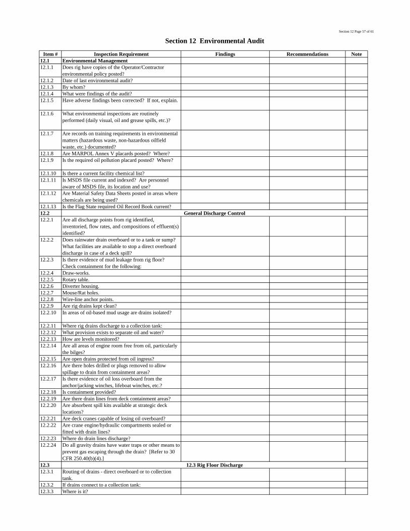
Section 12 Page 57 of 61
Item # Inspection Requirement Findings Recommendations Note12.1 Environmental Management12.1.1 Does rig have copies of the Operator/Contractor
environmental policy posted?12.1.2 Date of last environmental audit?12.1.3 By whom?12.1.4 What were findings of the audit?12.1.5 Have adverse findings been corrected? If not, explain.
12.1.6 What environmental inspections are routinelyperformed (daily visual, oil and grease spills, etc.)?
12.1.7 Are records on training requirements in environmentalmatters (hazardous waste, non-hazardous oilfieldwaste, etc.) documented?
12.1.8 Are MARPOL Annex V placards posted? Where?12.1.9 Is the required oil pollution placard posted? Where?
12.1.10 Is there a current facility chemical list?12.1.11 Is MSDS file current and indexed? Are personnel
aware of MSDS file, its location and use?12.1.12 Are Material Safety Data Sheets posted in areas where
chemicals are being used?12.1.13 Is the Flag State required Oil Record Book current?12.212.2.1 Are all discharge points from rig identified,
inventoried, flow rates, and compositions of effluent(s)identified?
12.2.2 Does rainwater drain overboard or to a tank or sump?What facilities are available to stop a direct overboarddischarge in case of a deck spill?
12.2.3 Is there evidence of mud leakage from rig floor?Check containment for the following:
12.2.4 Draw-works.12.2.5 Rotary table.12.2.6 Diverter housing.12.2.7 Mouse/Rat holes.12.2.8 Wire-line anchor points.12.2.9 Are rig drains kept clean?12.2.10 In areas of oil-based mud usage are drains isolated?
12.2.11 Where rig drains discharge to a collection tank:12.2.12 What provision exists to separate oil and water?12.2.13 How are levels monitored?12.2.14 Are all areas of engine room free from oil, particularly
the bilges?12.2.15 Are open drains protected from oil ingress?12.2.16 Are there holes drilled or plugs removed to allow
spillage to drain from containment areas?12.2.17 Is there evidence of oil loss overboard from the
anchor/jacking winches, lifeboat winches, etc.?12.2.18 Is containment provided?12.2.19 Are there drain lines from deck containment areas?12.2.20 Are absorbent spill kits available at strategic deck
locations?12.2.21 Are deck cranes capable of losing oil overboard?12.2.22 Are crane engine/hydraulic compartments sealed or
fitted with drain lines?12.2.23 Where do drain lines discharge?12.2.24 Do all gravity drains have water traps or other means to
prevent gas escaping through the drain? [Refer to 30CFR 250.40(b)(4).]
12.312.3.1 Routing of drains - direct overboard or to collection
tank.12.3.2 If drains connect to a collection tank:12.3.3 Where is it?
Section 12 Environmental Audit
General Discharge Control
12.3 Rig Floor Discharge

Section 12 Page 58 of 61
Item # Inspection Requirement Findings Recommendations Note12.3.4 Are there alarms on it?12.3.5 Where does mud bucket discharge?12.3.6 Is rig fitted with a drip tray under the rotary table?
Where does it discharge?12.3.7 Are mouse-hole and rat-hole blanked off? Where do
they discharge?12.3.8 Where is the standpipe bled to?12.3.9 Where does the Draw-works chain lube oil tank
discharge?12.3.10 Where does the rotary gear oil tank discharge?12.3.11 Where does the Draw-works cooling water discharge if
drained?12.3.12 What type of inhibitor is used?12.3.13 Where is the Elmagco brake system discharge?12.3.14 Is there any leakage from the slip joint?12.412.4.1 Are the mud and charging pumps within a containment
area?12.4.2 Where does the containment area(s) drain?12.4.3 Where are the pop-off lines routed?12.512.5.1 Are there locking devices on the dump valves?12.5.2 Is there a common drain for all the dump valves? Is
there a master dump valve in the common drain line?
12.5.3 Are the suction lines recessed into the bottom of thepits?
12.5.4 Are the pits able to be completely emptied withoutdischarging into the sea?
12.5.5 Are mud pits covered?12.5.6 Where does the sink in the pit room drain?12.5.7 Is there good ventilation in the pit room?12.612.6.1 Where do the drains from this area lead?12.6.2 Is the proper equipment available for handling drums?
12.6.3 Are the mixing pumps within containment and wheredoes the area drain?
12.6.4 Is the air around the mixing hoppers well ventilatedand filtered?
12.6.5 When the deck is washed down, where does it drain?
12.712.7.1 Are the open sections of flow-line fitted with splash
guards?12.7.2 Is the header box designed to prevent rig roll losses?
12.7.3 Is there a high pressure wash-down system in theshaker area?
12.7.4 What is the condition of the cutting retaining wall atthe end of the shakers?
12.7.5 Where are the drains routed on the shaker deck?12.7.6 Is the area ventilated?12.7.7 Where does the cutting's chute go?12.7.8 Where does the discharge from the "gumbo box" go?
12.812.8.1 Are the dump valves lockable? Are they locked?12.8.2 Is there a common drain line with a master dump
valve?12.8.3 Does the drain line go overboard or elsewhere?12.8.4 Can the sand-traps be completely emptied without
discharge to the sea?12.8.5 How are the centrifugal pumps for desilter, desander,
or centrifuges inside containment? Where does thecontainment drain?
12.8.6 Where does the discharge from the solids removalequipment go?
Shakers
Sand-traps
Mud Pump Room
Mud Pit Room
Sack Room/Mud Mixing Area

Section 12 Page 59 of 61
Item # Inspection Requirement Findings Recommendations Note12.912.9.1 Is the dump valve lockable? Is it locked?12.9.2 Where does the dump line discharge?12.9.3 Where does the overflow line discharge?12.9.4 Is the trip tank pump inside containment? Where does
the containment drain?12.1012.10.1 What is the condition of the hoses and spares?12.10.2 Are there dedicated hoses for brine, base oil, fuel oil,
cement, barite, etc.?12.1112.11.1 Is all excess bulk back-loaded or blown off?12.11.2 Are vents to all bulk tanks filtered before discharging
into the atmosphere?12.1212.12.1 Is waste separated into paper/metal/general waste, etc.,
so it can be recycled or sent to a landfill?12.12.2 What happens to damaged sacks of chemicals?12.12.3 What happens to empty plastic and metal drums?12.12.4 What happens to galley waste?12.1312.13.1 Where are the sinks routed?12.13..2 Are there suitable receptacles for waste chemicals,
etc.?12.1412.14.1 Where is the BOP control fluid discharged?12.14.2 What is type of BOP fluid in service?12.1512.15.1 Where is the excess mix water put or discharged?12.15.2 What happens to cement contaminated mud returns?12.15.3 Where do trail mixes of cement get put or discharged?
12.15.4 Where does tank cleaning effluent go?12.15.5 Where are the cement unit/lines flushed?12.15.6 Where is the cement surge tank emptied?12.1612.16.1 Are all produced hydrocarbons and cushions flared?
12.16.2 Is produced water dumped overboard?12.16.3 Is mercury free sampling performed?12.16.4 Are sand analysis and oil gravity tests collected in
waste oil drums and sent to town?12.1712.17.1 Where are the sinks routed?12.17.2 Where does the parts washer discharge?12.17.3 What type of solvent is used?12.17.4 Is there containment around all main generators?12.17.5 Where does the waste oil go?12.17.6 Where are deck drains in the engine room routed?12.1812.18.1 Where do the washing machines used in the
accommodations area discharge?12.18.2 Where does the gray water (galley, sinks, lavatories,
showers, etc.) go?12.1912.19.1 Where does the deck washing discharge?12.2012.20.1 Where does foam from fire drills discharge?12.20.2 Are Halon systems installed?12.2112.21.1 Who is responsible for handling waste, refuse, and
trash on the rig?12.21.2 What type of training have they received?12.21.3 When was the training conducted?12.21.4 Who is responsible for completing waster
manifests/shipping documents on the rig?12.21.5 What type of training have they received?12.21.6 When was the training conducted?
Main Deck
Firefighting
Waste Management
Mud Lab / Mud Logging / Wireline Unit
Koomey Unit
Cement Unit
Production Test Area
Engine Room
Accommodations
Trip Tank
Bulk and Fluid Transfer Hoses
Bulk System
Waste Containers

Section 12 Page 60 of 61
Item # Inspection Requirement Findings Recommendations Note12.21.7 Are waste shipments properly manifested?12.21.8 Are copies of manifests maintained on the unit?12.21.9 Are they accurate and complete?12.21.10 Do provisions exist for the recycling of waste?12.21.11 Are any programs or policies in effect to minimize the
generation of wastes (waste minimization)?12.21.12 Are wastes stored in proper receptacles (i.e., as not to
create a health hazard, containers netted, etc.)?
12.21.13 Is trash burned? Describe.12.21.14 Is there a trash compactor on the rig?12.21.15 Is there a garbage grinder on the rig?12.21.16 How are empty containers for drilling mud chemicals
(bags, plastic pails, barrels, etc.) disposed?
12.21.17 Are waste oil containers being sealed and tested forhalogens?
12.21.18 Are waste oil manifests being properly completed?12.2212.22.1 Are diesel lines to the pit room isolated or blanked?
12.22.2 Are records of calibration of mud level indicatorspresent?
12.22.3 Are records of all mud pit volumes kept at all times?
12.2312.23.1 What provisions are provided for overflow and vents
on storage tanks?12.2412.24.1 How are fuel filters and centrifuge waste disposed?12.24.2 Is diesel fuel centrifuge package in a containment area?
12.2512.25.1 Are written procedures available on the unit for oil and
fuel transfers? (Refer to 33 CFR 155.720.)12.25.2 Are procedures maintained current?12.25.3 Are oil/diesel transfers properly documented?12.25.4 Do vents and bunkering stations have appropriate
containments?12.25.5 Are all check and isolation valves in good order?12.25.6 Are hoses used for oil or diesel transfer marked with
words "Oil Service", the maximum allowable workingpressure, date of manufacture, and the latest test date?MAWP must be at least 150 PSI. Oil transfer hosesmust be tested annually. (Refer to 33 CFR 154.500,155.899, 156.170.)
12.25.7 Are there any interconnections between fuel, chemical,base oil, or oil-based mud systems and the open drains,seawater, potable water, ballast water, or other systemswhich have the potential to discharge overboard?
12.2612.26.1 What type of sewage treatment equipment is used on
the rig?12.26.2 Are results of overboard discharge testing from sewage
treatment plant current?12.26.3 Who is responsible for sewage treatment plant
sampling?12.2712.27.1 Is the required CFC recovery and recycle equipment
aboard? (Refer 40 CFR 82 subpart F.)12.27.2 Are consumption records maintained for CFC's?12.2812.28.1 Are spill absorption kits or suitable stocks of materials
immediately available for dealing with spillages?
12.28.2 Are a range of bungs for open drains similarlyavailable?
Oil/Fuel Transfer
Sewage Treatment Equipment
Refrigeration Units (CFC's)
Spill Contingency
Mud System
Storage Tanks
Diesel Filters/Centrifuges

Section 12 Page 61 of 61
Item # Inspection Requirement Findings Recommendations Note12.28.3 Are all personnel aware of this equipment and its
purpose?12.28.4 Is there a copy of the Operator's oil spill contingency
plan available for inspection?12.28.5 Is spill reporting information (contact and telephone
numbers) posted for easy access?12.28.6 Are procedures in place for reporting all spills and
environmental incidents?12.28.7 Are records kept of reported spills and incidents?12.2912.29.1 Are all work areas clean and tidy?12.29.2 Is rig wash being used of a type proven to be
environmentally acceptable for the operating area?12.29.3 Do drums which are in use have visible labels?12.29.4 Are drum storage areas tidy and drums fitted with drip
trays when in use?12.29.5 Are drums in containment areas?12.29.6 Is the waste oil tank located away from an open drain?
12.29.7 Chemical Storage:12.29.8 Are chemical pallets stored to prevent falling?12.29.9 Are chemical pallets properly labeled?12.29.10 Are chemicals stored in a segregated fashion?12.29.11 Is storage area tidy?12.29.12 Can stored chemicals be released to the environment?
12.29.13 Does containment exist in liquid chemical storageareas?
Maintenance and Housekeeping