ibc-sw installation manual - eaton · eaton 93pm integrated battery cabinet-small welded (ibc-sw)...
TRANSCRIPT

p/n: 164000639Revision 03
IBC-SWInstallation Manual
Eaton® 93PM Integrated Battery Cabinet-Small Welded

Eaton reserves the right to change specifications without prior notice. Modbus is a registered trademark of Schneider Automation, Inc.MOXA is a registered trademark and MGate is a trademark of MOXA, Inc. Spiralock is a registered trademark of Spiralock Corporation.KIRK is a registered trademark of Kirk Key Interlock company, LLC, a subsidiary of Halma plc. National Electrical Code and NEC areregistered trademarks of National Fire Protection Association, Inc. ERIFLEX and FLEXIBAR are registered trademark of Erico InternationalCorporation. All other trademarks are property of their respective companies.
©Copyright 2017-2019 Eaton, Raleigh, NC, USA. All rights reserved. No part of this document may be reproduced in any way without theexpress written approval of Eaton.
IMPORTANT SAFETY INSTRUCTIONS SAVE THESE INSTRUCTIONS
This manual contains important instructions that should be followed during installation andmaintenance of the UPS and batteries. Read all instructions before operating the equipment and savethis manual for future reference.
CONSIGNES DE SÉCURITÉ IMPORTANTES — CONSERVER CES INSTRUCTIONS
Ce manuel comporte des instructions importantes que vous êtes invité à suivre lors de touteprocédure d'installation et de maintenance des batteries et de l'onduleur. Veuillez consulterentièrement ces instructions avant de faire fonctionner l'équipement et conserver ce manuel afin depouvoir vous y reporter ultérieurement.
! IMPORTANTTo ensure you have the most up-to-date content and information for this product, please review thelatest manual revision on our website, www.eaton.com/93PM.

Eaton 93PM Integrated Battery Cabinet-Small Welded (IBC-SW) Installation Manual 164000639—Rev 03 iii
TTaabbllee ooff CCoonntteennttss
11 IInnttrroodduuccttiioonn .................................................................................................................................................................................................................................................................................................... 111.1 Installation Features ....................................................................................................................................2
1.2 Optional Thermal Sensor ..............................................................................................................................2
1.3 Model Configurations ..................................................................................................................................3
1.4 Using This Manual ......................................................................................................................................3
1.5 Conventions Used in This Manual ..................................................................................................................3
1.6 Symbols, Controls, and Indicators ..................................................................................................................4
1.7 For More Information ..................................................................................................................................4
1.8 Getting Help ..............................................................................................................................................5
1.9 Equipment Registration ...............................................................................................................................5
22 SSaaffeettyy WWaarrnniinnggss........................................................................................................................................................................................................................................................................................ 77
33 IInnssttaallllaattiioonn PPllaann aanndd UUnnppaacckkiinngg ...................................................................................................................................................................................................................................... 11113.1 Creating an Installation Plan ........................................................................................................................ 11
3.2 Preparing the Site ..................................................................................................................................... 11
3.2.1 Environmental and Installation Considerations .......................................................................................... 11
3.2.2 IBC–SW Power Wiring Preparation ......................................................................................................... 16
3.2.3 IBC–SW Interface Wiring Preparation...................................................................................................... 18
3.3 Inspecting and Unpacking the Eaton 93PM IBC–SW ........................................................................................ 19
3.4 Battery Breaker Location ............................................................................................................................ 21
44 IInnssttaallllaattiioonn .................................................................................................................................................................................................................................................................................................. 22334.1 Preliminary Installation Information............................................................................................................... 23
4.2 Unloading the IBC Cabinet from the Pallet...................................................................................................... 23
4.3 Installing Power Wiring .............................................................................................................................. 29
4.3.1 Line-Up-and-Match Power Wiring........................................................................................................... 29
4.3.2 Standalone Power Wiring ..................................................................................................................... 34
4.4 Installing IBC–SW Interface Wiring ............................................................................................................... 36
4.4.1 Installing Battery Detect Interface Connections ......................................................................................... 36
4.4.2 Installing Battery Shunt Trip Interface Connections .................................................................................... 41
4.4.3 Installing Thermal Sensor Interface Connections ....................................................................................... 43
4.5 Initial Startup ........................................................................................................................................... 44
4.6 Completing the Installation Checklist ............................................................................................................ 44
55 OOnneelliinneess aanndd SScchheemmaattiiccss .......................................................................................................................................................................................................................................................... 44775.1 Power Onelines ....................................................................................................................................... 47
5.2 Interface Onelines .................................................................................................................................... 49
5.3 Schematics ............................................................................................................................................. 49
66 MMaaiinntteennaannccee.............................................................................................................................................................................................................................................................................................. 55336.1 Important Safety Instructions ...................................................................................................................... 53

iv Eaton 93PM Integrated Battery Cabinet-Small Welded (IBC-SW) Installation Manual 164000639—Rev 03
6.2 Performing Preventive Maintenance............................................................................................................. 53
6.2.1 DAILY Maintenance ............................................................................................................................ 53
6.2.2 PERIODIC Maintenance ....................................................................................................................... 53
6.2.3 ANNUAL Maintenance......................................................................................................................... 53
6.2.4 BATTERY Maintenance........................................................................................................................ 53
6.2.5 BATTERY Shelf Life............................................................................................................................. 54
6.3 Recycling the Used Batteries ...................................................................................................................... 54
6.4 Maintenance Training ................................................................................................................................ 54
77 PPrroodduucctt SSppeecciiffiiccaattiioonnss ................................................................................................................................................................................................................................................................ 55557.1 Models................................................................................................................................................... 55
7.2 Specifications .......................................................................................................................................... 55
7.2.1 Battery Specifications .......................................................................................................................... 55
7.2.2 Environmental and Safety Specifications.................................................................................................. 56
88 WWaarrrraannttyy ........................................................................................................................................................................................................................................................................................................ 55778.1 Limited Factory Warranty for Three-Phase Eaton 93PM UPS and 93PM UPS Accessory Products.............................. 57
Table of Contents

Eaton 93PM Integrated Battery Cabinet-Small Welded (IBC-SW) Installation Manual 164000639—Rev 03 v
LLiisstt ooff FFiigguurreess
Figure 1. Eaton 93PM Integrated Battery Cabinet–Small Welded ..........................................................................1
Figure 2. Eaton 93PM UPS and Two 93PM IBC–SWs — Various Configurations.......................................................2
Figure 3. Eaton 93PM Integrated Battery Cabinet–Small Welded Dimensions (Front, Right Side, and RearViews) ....................................................................................................................................... 13
Figure 4. Eaton 93PM IBC–SW Dimensions (Top and Bottom Views)................................................................... 14
Figure 5. Eaton 93PM IBC–SW Center of Gravity............................................................................................. 15
Figure 6. Eaton 93PM IBC–SW as Shipped on Pallet ........................................................................................ 20
Figure 7. Eaton 93PM IBC–SW Battery Breaker Locations – Front View with Cover Removed................................... 21
Figure 8. Removing the Pallet Skids and Supports – Eaton 93PM Integrated Battery Cabinet .................................... 25
Figure 9. Line-Up-and-Match Wiring Access Locations...................................................................................... 27
Figure 10. Rear Ventilation ........................................................................................................................... 28
Figure 11. Top Ventilation............................................................................................................................. 29
Figure 12. Wiring Channel Location ................................................................................................................ 31
Figure 13. DC Power Terminal Locations – Eaton 93PM IBC–SW.......................................................................... 32
Figure 14. Wire Tie Anchors ......................................................................................................................... 33
Figure 15. DC Power Terminal Detail – Eaton 93PM IBC–SW............................................................................... 33
Figure 16. Top and Bottom Entry Conduit and Wire Entry Locations ...................................................................... 36
Figure 17. Interface Terminal Locations – Eaton 93PM IBC–SW ........................................................................... 38
Figure 18. Shunt Trip, Battery Detect, and Thermal Sensor Wiring ........................................................................ 40
Figure 19. Interface Terminal Detail – Eaton 93PM IBC–SW ................................................................................ 41
Figure 20. 93PM Integrated Battery Cabinet Line-Up-and-Match Power Oneline ...................................................... 47
Figure 21. 93PM Integrated Battery Cabinet Standalone Power Online – One or Two Cabinets ................................... 48
Figure 22. 93PM Integrated Battery Cabinet Standalone Power Online – Three or Four Cabinets ................................. 48
Figure 23. 93PM Integrated Battery Cabinet Interface Oneline ............................................................................. 49
Figure 24. 93PM Integrated Battery Cabinet Schematic...................................................................................... 50
Figure 25. 93PM Integrated Battery Cabinet — Battery String Detail Schematic....................................................... 51

vi Eaton 93PM Integrated Battery Cabinet-Small Welded (IBC-SW) Installation Manual 164000639—Rev 03
List of Figures
Eaton 93PM Integrated Battery Cabinet-Small Welded (IBC-SW) Installation Manual 164000639—Rev 03 vii
LLiisstt ooff TTaabblleess
Table 1. IBC-SW Cabinet Weights ................................................................................................................ 12
Table 2. IBC-SW Cabinet Clearances............................................................................................................. 13
Table 3. Line-Up-and-Match External Power Wiring Recommendations: Eaton 93PM IBC-SW (432V or 480V) .............. 17
Table 4. Standalone External Power Wiring Recommendations: Eaton 93PM IBC-SW (432V or 480V) ......................... 17
Table 5. External Power Cable Terminations for the Eaton 93PM IBC-SW ............................................................. 18
Table 6. Recommended DC Circuit Breaker or Disconnect Ratings (Three or Four IBCs)........................................... 18
Table 7. IBC TB2 Interface Connections......................................................................................................... 38
Table 8. IBC TB2 Interface Wiring Terminal Block Terminations .......................................................................... 39

viii Eaton 93PM Integrated Battery Cabinet-Small Welded (IBC-SW) Installation Manual 164000639—Rev 03
List of Tables
Eaton 93PM Integrated Battery Cabinet-Small Welded (IBC-SW) Installation Manual 164000639—Rev 03 1
CChhaapptteerr 11 IInnttrroodduuccttiioonn
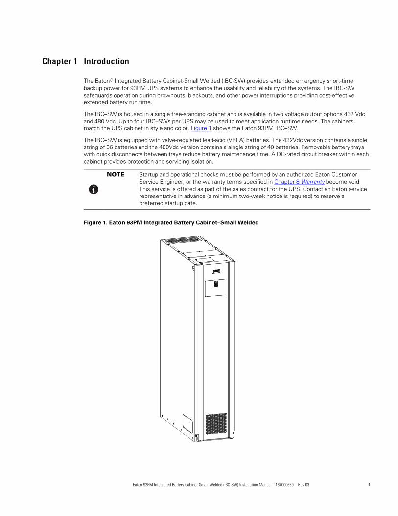
The Eaton® Integrated Battery Cabinet-Small Welded (IBC-SW) provides extended emergency short-timebackup power for 93PM UPS systems to enhance the usability and reliability of the systems. The IBC-SWsafeguards operation during brownouts, blackouts, and other power interruptions providing cost-effectiveextended battery run time.
The IBC–SW is housed in a single free-standing cabinet and is available in two voltage output options 432 Vdcand 480 Vdc. Up to four IBC–SWs per UPS may be used to meet application runtime needs. The cabinetsmatch the UPS cabinet in style and color. Figure 1 shows the Eaton 93PM IBC–SW.
The IBC–SW is equipped with valve-regulated lead-acid (VRLA) batteries. The 432Vdc version contains a singlestring of 36 batteries and the 480Vdc version contains a single string of 40 batteries. Removable battery trayswith quick disconnects between trays reduce battery maintenance time. A DC-rated circuit breaker within eachcabinet provides protection and servicing isolation.
NOTE Startup and operational checks must be performed by an authorized Eaton CustomerService Engineer, or the warranty terms specified in Chapter 8 Warranty become void.This service is offered as part of the sales contract for the UPS. Contact an Eaton servicerepresentative in advance (a minimum two-week notice is required) to reserve apreferred startup date.
Figure 1. Eaton 93PM Integrated Battery Cabinet–Small Welded

2 Eaton 93PM Integrated Battery Cabinet-Small Welded (IBC-SW) Installation Manual 164000639—Rev 03
11..11 IInnssttaallllaattiioonn FFeeaattuurreess• Line-up-and-match configurations using factory supplied power wiring or standalone configurations using
customer supplied power wiring
• Battery wiring can be run internally through the left or right sides of the IBC–SWs in line-up-and-matchconfigurations, or routed through the top or bottom of the IBC–SWs using conduit in standaloneconfigurations
• Front access panel for access to the battery breaker
• Interface wiring can be routed through the top left or right sides of the IBC–SWs in line-up-and-matchconfigurations or through the top or bottom of the IBC–SWs using conduit in standalone configurations
• Built-in casters for easy cabinet placement
• Cabinet bolt holes are provided for permanently mounting the IBC–SW using the optional Floor MountBracket Kit
Line-up-and-match battery cabinets are installed adjacent to the UPS. The IBC-SW can be installed on either theleft or right side or on both sides of the UPS cabinet (see Figure 2).
Figure 2. Eaton 93PM UPS and Two 93PM IBC–SWs — Various Configurations
Left Side IBC-SW Installation Right Side IBC-SW Installation Combination IBC-SW Installation
IBC-SW2 IBC-SW1 UPS UPS IBC-SW1 IBC-SW2 IBC-SW1 UPS IBC-SW2
11..22 OOppttiioonnaall TThheerrmmaall SSeennssoorrThermal runaway protection for VRLA batteries can be provided by installing an optional thermal sensor insidethe battery cabinet.
The sensor is wired to an UPS building alarm programmed to turn the charger off when a trip signal is received.
The thermal sensor will maintain the trip state until the temperature it is reset by service. Service should becalled to inspect the batteries and reset the sensor in case of such an event.
Introduction

Eaton 93PM Integrated Battery Cabinet-Small Welded (IBC-SW) Installation Manual 164000639—Rev 03 3
11..33 MMooddeell CCoonnffiigguurraattiioonnssThe following model configurations are available:
• 93PM Integrated Battery Cabinet-Small Welded
– Line-up-and-match, top entry, or bottom entry standalone
– Top or rear ventilation
– Contains one battery string with either 36 batteries (432 Vdc version) or 40 batteries (480 Vdc version)
– Available Eaton PWHR12200W4FR or CSB HRL12200WFR batteries
– Up to four IBC–SWs can be paralleled with a 93PM or 93PM-L UPS system to extend the runtime
11..44 UUssiinngg TThhiiss MMaannuuaallThis manual describes how to install the IBC–SW and is divided into chapters. Read and understand theprocedures described to ensure trouble-free installation and operation.
Read through each procedure before beginning the procedure. Perform only those procedures that apply to theUPS system being installed or operated.
Specifications listed in this manual are subject to change.
11..55 CCoonnvveennttiioonnss UUsseedd iinn TThhiiss MMaannuuaallThis manual uses these type conventions:
• Bold type highlights important concepts in discussions, key terms in procedures, and menu options, orrepresents a command or option that you type or enter at a prompt.
• Italic type highlights notes and new terms where they are defined.
• Screen type represents information that appears on the screen or LCD.
Icon Description
Note Information notes call attention to important features or instructions.
[Keys] Brackets are used when referring to a specific key, such as [Enter] or [Ctrl].
In this manual, the term UPS refers only to the UPS cabinet and its internal elements. The term UPS systemrefers to the entire power protection system – the UPS cabinet, an external battery system, and options oraccessories installed.
The term line-up-and-match refers to accessory cabinets that are physically located adjacent to the UPS. Theterm standalone refers to accessory cabinets that are located separate from the UPS.
Left and right side notations are referenced standing in front of the cabinet.
Introduction
4 Eaton 93PM Integrated Battery Cabinet-Small Welded (IBC-SW) Installation Manual 164000639—Rev 03
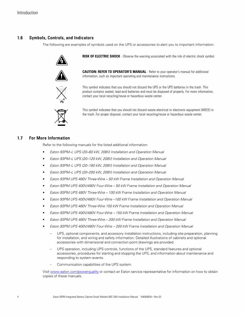
11..66 SSyymmbboollss,, CCoonnttrroollss,, aanndd IInnddiiccaattoorrssThe following are examples of symbols used on the UPS or accessories to alert you to important information:
Special Symbols
The following are examples of symbols used on the UPS or accessories to alert you to important
information:
RISK OF ELECTRIC SHOCK - Observe the warning associated with the risk of
electric shock symbol.
CAUTION: REFER TO OPERATOR'S MANUAL - Refer to your operator's manual for
additional information, such as important operating and maintenance
instructions.
This symbol indicates that you should not discard the UPS or the UPS batteries
in the trash. This product contains sealed, lead‐acid batteries and must be
disposed of properly. For more information, contact your local recycling/reuse or
hazardous waste center.
This symbol indicates that you should not discard waste electrical or electronic
equipment (WEEE) in the trash. For proper disposal, contact your local
recycling/reuse or hazardous waste center.
Eaton, Powerware, and BladeUPS are registered trademarks of Eaton Corporation or its subsidiaries and affiliates.
Phillips and Pozidriv are registered trademarks of Phillips Screw Company.
�Copyright 2008–2010 Eaton Corporation, Raleigh, NC, USA. All rights reserved. No part of this document may be
reproduced in any way without the express written approval of Eaton Corporation.
RISK OF ELECTRIC SHOCK - Observe the warning associated with the risk of electric shock symbol.
Special Symbols
The following are examples of symbols used on the UPS or accessories to alert you to important
information:
RISK OF ELECTRIC SHOCK - Observe the warning associated with the risk of
electric shock symbol.
CAUTION: REFER TO OPERATOR'S MANUAL - Refer to your operator's manual for
additional information, such as important operating and maintenance
instructions.
This symbol indicates that you should not discard the UPS or the UPS batteries
in the trash. This product contains sealed, lead‐acid batteries and must be
disposed of properly. For more information, contact your local recycling/reuse or
hazardous waste center.
This symbol indicates that you should not discard waste electrical or electronic
equipment (WEEE) in the trash. For proper disposal, contact your local
recycling/reuse or hazardous waste center.
Eaton, Powerware, and BladeUPS are registered trademarks of Eaton Corporation or its subsidiaries and affiliates.
Phillips and Pozidriv are registered trademarks of Phillips Screw Company.
�Copyright 2008–2010 Eaton Corporation, Raleigh, NC, USA. All rights reserved. No part of this document may be
reproduced in any way without the express written approval of Eaton Corporation.
CAUTION: REFER TO OPERATOR'S MANUAL - Refer to your operator's manual for additionalinformation, such as important operating and maintenance instructions.
Special Symbols
The following are examples of symbols used on the UPS or accessories to alert you to important
information:
RISK OF ELECTRIC SHOCK - Observe the warning associated with the risk of
electric shock symbol.
CAUTION: REFER TO OPERATOR'S MANUAL - Refer to your operator's manual for
additional information, such as important operating and maintenance
instructions.
This symbol indicates that you should not discard the UPS or the UPS batteries
in the trash. This product contains sealed, lead‐acid batteries and must be
disposed of properly. For more information, contact your local recycling/reuse or
hazardous waste center.
This symbol indicates that you should not discard waste electrical or electronic
equipment (WEEE) in the trash. For proper disposal, contact your local
recycling/reuse or hazardous waste center.
Eaton, Powerware, and BladeUPS are registered trademarks of Eaton Corporation or its subsidiaries and affiliates.
Phillips and Pozidriv are registered trademarks of Phillips Screw Company.
�Copyright 2008–2010 Eaton Corporation, Raleigh, NC, USA. All rights reserved. No part of this document may be
reproduced in any way without the express written approval of Eaton Corporation.
This symbol indicates that you should not discard the UPS or the UPS batteries in the trash. Thisproduct contains sealed, lead-acid batteries and must be disposed of properly. For more information,contact your local recycling/reuse or hazardous waste center.
Special Symbols
The following are examples of symbols used on the UPS or accessories to alert you to important
information:
RISK OF ELECTRIC SHOCK - Observe the warning associated with the risk of
electric shock symbol.
CAUTION: REFER TO OPERATOR'S MANUAL - Refer to your operator's manual for
additional information, such as important operating and maintenance
instructions.
This symbol indicates that you should not discard the UPS or the UPS batteries
in the trash. This product contains sealed, lead‐acid batteries and must be
disposed of properly. For more information, contact your local recycling/reuse or
hazardous waste center.
This symbol indicates that you should not discard waste electrical or electronic
equipment (WEEE) in the trash. For proper disposal, contact your local
recycling/reuse or hazardous waste center.
Eaton, Powerware, and BladeUPS are registered trademarks of Eaton Corporation or its subsidiaries and affiliates.
Phillips and Pozidriv are registered trademarks of Phillips Screw Company.
�Copyright 2008–2010 Eaton Corporation, Raleigh, NC, USA. All rights reserved. No part of this document may be
reproduced in any way without the express written approval of Eaton Corporation.
This symbol indicates that you should not discard waste electrical or electronic equipment (WEEE) inthe trash. For proper disposal, contact your local recycling/reuse or hazardous waste center.
11..77 FFoorr MMoorree IInnffoorrmmaattiioonnRefer to the following manuals for the listed additional information:
• Eaton 93PM–L UPS (20–60 kW, 208V) Installation and Operation Manual
• Eaton 93PM–L UPS (20–120 kW, 208V) Installation and Operation Manual
• Eaton 93PM–L UPS (20–160 kW, 208V) Installation and Operation Manual
• Eaton 93PM–L UPS (20–200 kW, 208V) Installation and Operation Manual
• Eaton 93PM UPS 480V Three-Wire – 50 kW Frame Installation and Operation Manual
• Eaton 93PM UPS 400V/480V Four-Wire – 50 kW Frame Installation and Operation Manual
• Eaton 93PM UPS 480V Three-Wire – 100 kW Frame Installation and Operation Manual
• Eaton 93PM UPS 400V/480V Four-Wire –100 kW Frame Installation and Operation Manual
• Eaton 93PM UPS 480V Three-Wire 150 kW Frame Installation and Operation Manual
• Eaton 93PM UPS 400V/480V Four-Wire – 150 kW Frame Installation and Operation Manual
• Eaton 93PM UPS 480V Three-Wire – 200 kW Frame Installation and Operation Manual
• Eaton 93PM UPS 400V/480V Four-Wire – 200 kW Frame Installation and Operation Manual
– UPS, optional components, and accessory installation instructions, including site preparation, planningfor installation, and wiring and safety information. Detailed illustrations of cabinets and optionalaccessories with dimensional and connection point drawings are provided.
– UPS operation, including UPS controls, functions of the UPS, standard features and optionalaccessories, procedures for starting and stopping the UPS, and information about maintenance andresponding to system events.
– Communication capabilities of the UPS system.
Visit www.eaton.com/powerquality or contact an Eaton service representative for information on how to obtaincopies of these manuals.
Introduction
Eaton 93PM Integrated Battery Cabinet-Small Welded (IBC-SW) Installation Manual 164000639—Rev 03 5
11..88 GGeettttiinngg HHeellppIf help is needed with any of the following:
• Scheduling initial startup
• Regional locations and telephone numbers
• A question about any of the information in this manual
• A question this manual does not answer
Please call the Customer Reliability Center at:
United States: 1-800-843-9433
Canada: 1–800-461-9166 ext 260
All other countries: Call your local service representative
Please use the following e-mail address for manual comments, suggestions, or to report an error in thismanual:
11..99 EEqquuiippmmeenntt RReeggiissttrraattiioonnPlease visit www.eaton.com/pq/register to register your new Eaton UPS / Eaton UPS Accessory.
Model Number:
Serial Number:
Introduction

6 Eaton 93PM Integrated Battery Cabinet-Small Welded (IBC-SW) Installation Manual 164000639—Rev 03
Introduction

Eaton 93PM Integrated Battery Cabinet-Small Welded (IBC-SW) Installation Manual 164000639—Rev 03 7
CChhaapptteerr 22 SSaaffeettyy WWaarrnniinnggss
IMPORTANT SAFETY INSTRUCTIONS SAVE THESE INSTRUCTIONS
This manual contains important instructions that should be followed during installation and maintenance of theUPS system and batteries. Read all instructions before operating the equipment and save this manual for futurereference.
The UPS system is designed for industrial or computer room applications, and contains safety shields behindthe door and front panels. However, the UPS system is a sophisticated power system and should be handledwith appropriate care.
DANGERThis UPS system contains LETHAL VOLTAGES. All repairs and service should be performed by AUTHORIZEDSERVICE PERSONNEL ONLY. There are NO USER SERVICEABLE PARTS inside the UPS.
WARNING
• The UPS system is powered by its own energy source (batteries). The output terminals may carry livevoltage even when the UPS is disconnected from an AC source.
• The battery cabinet contains its own energy source. The internal wiring and output terminals may carry livevoltage even when the UPS is not connected to an AC source.
• To reduce the risk of fire or electric shock, install this UPS system in a temperature and humiditycontrolled, indoor environment, free of conductive contaminants. Ambient temperature must not exceed40°C (104°F). Do not operate near water or excessive humidity (95% maximum). The system is notintended for outdoor use.
• As a result of the connected loads high leakage current is possible. Connection to earth ground is requiredfor safety and proper product operation. Do not check UPS system operation by any action that includesremoval of the earth (ground) connection with loads attached.
• Ensure all power is disconnected before performing installation or service.
• Batteries can present a risk of electrical shock or burn from high short-circuit current. The followingprecautions should be observed: 1) Remove watches, rings, or other metal objects; 2) Use tools withinsulated handles; 3) Do not lay tools or metal parts on top of batteries; 4) Wear voltage rated gloves andelectrical hazard footwear.
• ELECTRIC ENERGY HAZARD. Do not attempt to alter any UPS system or battery wiring or connectors.Attempting to alter wiring can cause injury.
• Do not open or mutilate batteries. Released electrolyte is harmful to the skin and eyes. It may be toxic.
8 Eaton 93PM Integrated Battery Cabinet-Small Welded (IBC-SW) Installation Manual 164000639—Rev 03
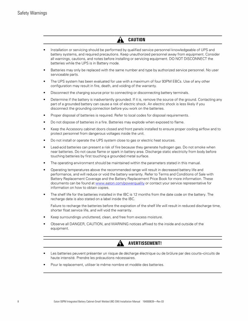
CAUTION
• Installation or servicing should be performed by qualified service personnel knowledgeable of UPS andbattery systems, and required precautions. Keep unauthorized personnel away from equipment. Considerall warnings, cautions, and notes before installing or servicing equipment. DO NOT DISCONNECT thebatteries while the UPS is in Battery mode.
• Batteries may only be replaced with the same number and type by authorized service personnel. No userserviceable parts.
• The UPS system has been evaluated for use with a maximum of four 93PM EBCs. Use of any otherconfiguration may result in fire, death, and voiding of the warranty.
• Disconnect the charging source prior to connecting or disconnecting battery terminals.
• Determine if the battery is inadvertently grounded. If it is, remove the source of the ground. Contacting anypart of a grounded battery can cause a risk of electric shock. An electric shock is less likely if youdisconnect the grounding connection before you work on the batteries.
• Proper disposal of batteries is required. Refer to local codes for disposal requirements.
• Do not dispose of batteries in a fire. Batteries may explode when exposed to flame.
• Keep the Accessory cabinet doors closed and front panels installed to ensure proper cooling airflow and toprotect personnel from dangerous voltages inside the unit.
• Do not install or operate the UPS system close to gas or electric heat sources.
• Lead-acid batteries can present a risk of fire because they generate hydrogen gas. Do not smoke whennear batteries. Do not cause flame or spark in battery area. Discharge static electricity from body beforetouching batteries by first touching a grounded metal surface.
• The operating environment should be maintained within the parameters stated in this manual.
• Operating temperatures above the recommended range will result in decreased battery life andperformance, and will reduce or void the battery warranty. Refer to Terms and Conditions of Sale withBattery Replacement Coverage and the Battery Replacement Price Book for more information. Thesedocuments can be found at www.eaton.com/powerquality or contact your service representative forinformation on how to obtain copies.
• The shelf life for the batteries installed in the IBC is 12 months from the date code on the battery. Therecharge date is also stated on a label inside the IBC.
Failure to recharge the batteries before the expiration of the shelf life will result in reduced discharge time,shorter float service life, and will void the warranty.
• Keep surroundings uncluttered, clean, and free from excess moisture.
• Observe all DANGER, CAUTION, and WARNING notices affixed to the inside and outside of theequipment.
AVERTISSEMENT!
• Les batteries peuvent présenter un risque de décharge électrique ou de brûlure par des courts–circuits dehaute intensité. Prendre les précautions nécessaires.
• Pour le replacement, utiliser le même nombre et modéle des batteries.
Safety Warnings
Eaton 93PM Integrated Battery Cabinet-Small Welded (IBC-SW) Installation Manual 164000639—Rev 03 9
ATTENTION!
• Une mise au rebut réglementaire des batteries est obligatoire. Consulter les règlements en vigueur dansvotre localité.
• Ne jamais jeter les batteries au feu. L'exposition aux flammes risque de les faire exploser.
• Les accumulateurs au plomb-acide peuvent représenter un risque d’incendie, car ils génèrent del’hydrogène gazeux. Ne pas fumer près des accumulateurs. Ne pas produire de flamme ou d’étincelle dansla zone de l’accumulateur. Dissiper l'électricité statique de votre corps en touchant une surface reliée à laterre avant de toucher les accumulateurs.
Safety Warnings

10 Eaton 93PM Integrated Battery Cabinet-Small Welded (IBC-SW) Installation Manual 164000639—Rev 03
Safety Warnings
Eaton 93PM Integrated Battery Cabinet-Small Welded (IBC-SW) Installation Manual 164000639—Rev 03 11
CChhaapptteerr 33 IInnssttaallllaattiioonn PPllaann aanndd UUnnppaacckkiinngg
Use the following basic sequence of steps to install the Eaton 93PM Integrated Battery Cabinet:
1. Create an installation plan for the IBC.
2. Prepare your site for the IBC.
3. Inspect and unpack the IBC.
4. Unload and install the IBC, and wire the system.
5. Complete the Installation Checklist.
6. Have authorized service personnel perform preliminary operational checks and start up the system.
NOTE Startup and operational checks must be performed by an authorized Eaton CustomerService Engineer, or the warranty terms specified in Chapter 8 Warranty become void.This service is offered as part of the sales contract for the UPS. Contact an Eaton servicerepresentative in advance (a minimum two-week notice is required) to reserve apreferred startup date.
33..11 CCrreeaattiinngg aann IInnssttaallllaattiioonn PPllaannBefore installing the IBC, read and understand how this manual applies to the system being installed. Use theprocedures and illustrations in this section and Chapter 4 Installation to create a logical plan for installingthe IBC. This section contains the following information:
• Physical features and requirements, including dimensions
• Power wiring installation notes
• Location of conduit and wire entry landing plates
• Location of power terminals
33..22 PPrreeppaarriinngg tthhee SSiitteeFor the UPS system to operate at peak efficiency, the installation site should meet the environmentalparameters outlined in this manual. The operating environment must meet the weight, clearance, andenvironmental requirements specified.
33..22..11 EEnnvviirroonnmmeennttaall aanndd IInnssttaallllaattiioonn CCoonnssiiddeerraattiioonnss
The UPS system installation, including the IBC, must meet the following guidelines:
• The system must be installed on a level floor suitable for computer or electronic equipment.
• The system must be operated at an altitude no higher than 1500m (5000 ft) without derating. For additionalinformation and assistance with high altitude operation, contact an Eaton service representative (seeparagraph 1.8 Getting Help).
• The system must be installed in a temperature and humidity controlled indoor area free of conductivecontaminants.
• Specifications are subject to change
Failure to follow guidelines may void your warranty.
The basic environmental requirements for operation of the IBC are:
• The battery cabinet is rated for operation in up to a 40°C (104°F) ambient temperature.
• The batteries are rated for a 25°C (77°F) ambient temperature to extend their useful life.

12 Eaton 93PM Integrated Battery Cabinet-Small Welded (IBC-SW) Installation Manual 164000639—Rev 03
• Maximum Relative Humidity: 5–95%, noncondensing
CAUTIONIt is recommended for optimal battery life and discharge performance to keep the ambient air temperature thebattery is used in at 25°C (77°F). Operating temperatures above the recommended range will result indecreased battery life and performance, and will reduce or void the battery warranty. Refer to Eaton's Termsand Conditions of Sale with Battery Replacement Coverage and the Battery Replacement Price Book for moreinformation. These documents can be found at www.eaton.com/powerquality or contact your servicerepresentative for information on how to obtain copies.
CAUTIONThe shelf life for the batteries installed in the IBC is 12 months from the date code on the battery. The rechargedate is also stated on a label inside the IBC.
Failure to recharge the batteries before the expiration of the shelf life will result in reduced discharge time,shorter float service life, and will void the warranty.
The IBC–SW operating environment must meet the weight requirements shown in Table 1 and the sizerequirements shown in Figure 3 through Figure 5. Dimensions are in millimeters (inches). Specifications aresubject to change.
Table 1. IBC-SW Cabinet Weights
Model
Weight kg (lb)
Voltage Shipping Installed Point Loading
Eaton 93PM IBC–SWwith 1 battery string (36 batteries)
432V 935 (2061) 908 (2001) 6 at 151 (334)
Eaton 93PM IBC–SWwith 1 battery string (40 batteries)
480V 1007 (2219) 980 (2159) 6 at 163 (360)
Eaton 93PM IBC–SWShipped without batteries
432V 301 (665)
Eaton 93PM IBC–SWShipped without batteries
480V 303 (667)
The IBC–SW uses natural convection cooling to regulate internal component temperature. Air inlets are in thefront of the cabinet and outlets are on the back or top of the cabinet. Allow clearance in front of, and on back ortop of the cabinet for proper air circulation. The clearances required around the IBC–SW cabinet are shown inTable 2.
Installation Plan and Unpacking

Eaton 93PM Integrated Battery Cabinet-Small Welded (IBC-SW) Installation Manual 164000639—Rev 03 13
Table 2. IBC-SW Cabinet Clearances
From Top of Cabinet with Rear Exhaust Option 203.2 mm (8") minimum clearance
From Top of Cabinet with Top Exhaust Option 203.2 mm (8") minimum clearance
From Front of Cabinet 914.4 mm (36") working space
From Back of Cabinet with Top Exhaust Option None Required
From Back of Cabinet with Rear Exhaust Option 203.2 mm (8") minimum clearance
From Right Side of Cabinet None Required
From Left Side of Cabinet None Required
Figure 3. Eaton 93PM Integrated Battery Cabinet–Small Welded Dimensions (Front, Right Side, andRear Views)
1880[74.0]
425 [16.7]
1067 [42.0]
330 [13.0]
242 [9.5] 330 [13.0]58 [2.3]
47 [1.9]
60 [2.4]30 [1.2]
245 [9.6] 30 [1.2]
39 [1.5]
149[5.9]
79[3.1]
340[13.4]
Dimensions are in millimeters [inches]
Covered by a platewhen configuredfor top ventilation
Installation Plan and Unpacking

14 Eaton 93PM Integrated Battery Cabinet-Small Welded (IBC-SW) Installation Manual 164000639—Rev 03
Figure 4. Eaton 93PM IBC–SW Dimensions (Top and Bottom Views)
31[1.2]
340[13.4]
149[5.9]
833[32.8]
134[5.3]
69[2.7]
166[6.5]
102[4.0]
150[5.9]
757[29.8]
138[5.4]
Covered by a platewhen configuredfor rear ventilation
Dimensions are in millimeters [inches]
Installation Plan and Unpacking
Eaton 93PM Integrated Battery Cabinet-Small Welded (IBC-SW) Installation Manual 164000639—Rev 03 15
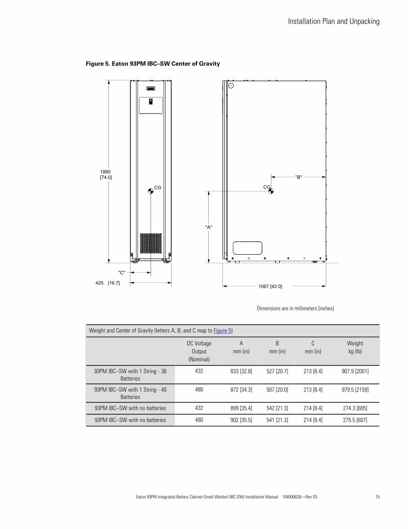
Figure 5. Eaton 93PM IBC–SW Center of Gravity
1880[74.0]
425 [16.7]1067 [42.0]
"C"
"B"
"A"
CGCG
Dimensions are in millimeters [inches]
Weight and Center of Gravity (letters A, B, and C map to Figure 5)
DC VoltageOutput
(Nominal)
Amm (in)
Bmm (in)
Cmm (in)
Weightkg (lb)
93PM IBC–SW with 1 String - 36Batteries
432 833 [32.8] 527 [20.7] 213 [8.4] 907.9 [2001]
93PM IBC–SW with 1 String - 40Batteries
480 872 [34.3] 507 [20.0] 213 [8.4] 979.5 [2159]
93PM IBC–SW with no batteries 432 899 [35.4] 542 [21.3] 214 [8.4] 274.3 [605]
93PM IBC–SW with no batteries 480 902 [35.5] 541 [21.3] 214 [8.4] 275.5 [607]
Installation Plan and Unpacking

16 Eaton 93PM Integrated Battery Cabinet-Small Welded (IBC-SW) Installation Manual 164000639—Rev 03
33..22..22 IIBBCC––SSWW PPoowweerr WWiirriinngg PPrreeppaarraattiioonn
Read and understand the following notes while planning and performing the installation:
WARNINGAs a result of the connected loads high leakage current is possible. Connection to earth ground is required forsafety and proper product operation. Do not check IBC–SW operation by any action that includes removal of theearth (ground) connection with loads attached.
• Refer to national and local electrical codes for acceptable external wiring practices.
• Material and labor for external wiring requirements are to be provided by the customer.
• For external wiring, use only 75°C copper wire.
! IMPORTANTThis product has been evaluated for use with copper wire only.
Wire sizes listed in Table 3 and Table 4 are for copper wiring only. If wire is run in an ambient temperaturegreater than 40°C, higher temperature wire and/or larger size wire may be necessary. Wire sizes are basedon using the specified breakers.
• Recommended wire sizes are based on NFPA National Electrical Code® (NEC®)70 Table 310.15(B)(16) 75°C ampacity with 40°C ambient correction factors.
• The battery wiring used between the battery and the UPS for standalone installations should be amaximum of 20 meters (65 feet) with a voltage drop of less than 1% of nominal DC voltage at ratedbattery current.
• Refer to NEC Article 250 and local codes for proper grounding practices.
• Battery voltage is computed at 2 volts per cell as defined by Article 480 of the NEC. Rated battery currentis computed at 2 volts per cell.
• The battery cabinet frame is not referenced to the DC circuit.
• Each battery cabinet has its own overcurrent protection device.
• Internal battery strings are to be connected by an authorized Eaton Customer Service Engineer.
• Refer to the appropriate Eaton 93PM UPS Installation and Operation manual listed in paragraph1.7 For More Information for UPS cabinet conduit and terminal specifications and locations.
• The term line-up-and-match refers to accessory cabinets that are physically located adjacent to the UPS.The term standalone refers to accessory cabinets that are located separate from the UPS.
For line-up-and-match external power wiring requirements, including the minimum AWG size of external wiring,see Table 3. For standalone external power wiring requirements, including the minimum AWG size of externalwiring, see Table 4. Wire sizes listed are for copper wiring only.
Installation Plan and Unpacking

Eaton 93PM Integrated Battery Cabinet-Small Welded (IBC-SW) Installation Manual 164000639—Rev 03 17
Table 3. Line-Up-and-Match External Power Wiring Recommendations: Eaton 93PM IBC-SW (432V or 480V)
Battery Cabinet to UPS
UPS Frame
MinimumNumberof BatteryCabinets Terminal
RecommendedConductor Size(AWG or kcmil) Number per Pole
50 kW 1 Battery (+)
Battery (–)
Ground
Factory Supplied 2/0
Factory Supplied 2/0
#4
1
1
one per cabinet
100 kW 2
150 kW 3
200 kW 3
NOTE Standalone IBC–SW installations with three or four IBC–SWs require a customersupplied external tie point and circuit breaker or disconnect between the IBC–SWs andthe UPS.
Table 4. Standalone External Power Wiring Recommendations: Eaton 93PM IBC-SW (432V or 480V)
Battery Cabinet to UPS orExternal Customer Supplied Tie
Pointand Breaker or Disconnect
Tie Point and Breakeror Disconnect to UPS
UPSFrame
MinimumNumberof BatteryCabinets Terminal
RecommendedConductor Size(AWG or kcmil)
Numberper Pole
RecommendedConductor Size(AWG or kcmil)
Numberper Pole
50 kW 1 Battery (+) 2/0 2 Not Required
100 kW 2 Battery (–) 2/0 2 Not Required
150 kW 3 Battery (+) 2/0 2 2/0 2
200 kW 3 Battery (–) 2/0 2 2/0 2
Ground #4 oneper cabinet
#4 one per cabinet
The power wiring terminals are pressure terminations, UL and CSA rated at 90°C. See Table 5 for externalpower cable terminations.
Figure 13 and Figure 15 show the location of the IBC power cable terminals.
Installation Plan and Unpacking

18 Eaton 93PM Integrated Battery Cabinet-Small Welded (IBC-SW) Installation Manual 164000639—Rev 03
Table 5. External Power Cable Terminations for the Eaton 93PM IBC-SW
ModelTerminalFunction Terminal Function
Number and Size ofPressure Termination
TighteningTorque Nm (lb in)
Screw Sizeand Type
IBC-SWDC Output
Battery + Positive 2 - #6-250 kcmil 31 (275) 5/16" Hex
Battery – Negative 2 - #6-250 kcmil 31 (275) 5/16" Hex
Customer Ground Ground Ground 6 - #6-1/0 5.1 (45) Slotted
NOTE Customer ground, sized in accordance with NEC Table 250.122, can be run in any conduit listed. Refer to the appropriateUPS manual.
External DC input overcurrent protection and disconnect switch for the remote battery location (three or fourIBC–SWs) is to be provided by the customer. Table 6 lists the maximum rating for continuous-duty rated circuitbreakers satisfying the criteria for both.
Table 6. Recommended DC Circuit Breaker or Disconnect Ratings (Three or Four IBCs)
Model UPS Model Input Rating
IBC-SW
50 kW100 kW150 kW200 kW
250A
33..22..33 IIBBCC––SSWW IInntteerrffaaccee WWiirriinngg PPrreeppaarraattiioonn
Control wiring for features and options should be connected at the customer interface terminal blocks locatedinside the IBC–SW.
WARNINGDo not directly connect relay contacts to the mains related circuits. Reinforced insulation to the mains isrequired.
Read and understand the following notes while planning and performing the installation:
• Use Class 1 wiring methods (as defined by the NEC) for interface wiring from 30V to 600V. The wireshould be rated for 600V, 1A minimum. 12 AWG maximum wire size.
• Use Class 2 wiring methods (as defined by the NEC) for interface wiring up to 30V. The wire should berated for 24V, 1A minimum.
• Because of the battery shunt trip wiring route in the 93PM UPS cabinet, the wiring from the IBC to theUPS must use wire rated for 600V and Class 1 wiring methods.
• The battery detect signal wiring from the battery cabinet must be connected to a programmed UPSbuilding alarm.
• Battery detect and 48 Vdc shunt trip wiring should be a minimum of 18 AWG.
• Use twisted-pair wires for each input and return or common.
• All interface wiring and conduit is to be supplied by the customer.
• Interface wiring can be installed using the inter-cabinet wiring access pass-through or by routing wiringthrough conduit between cabinets.
Installation Plan and Unpacking

Eaton 93PM Integrated Battery Cabinet-Small Welded (IBC-SW) Installation Manual 164000639—Rev 03 19
• Install the interface wiring in separate conduit from the power wiring.
33..33 IInnssppeeccttiinngg aanndd UUnnppaacckkiinngg tthhee EEaattoonn 9933PPMM IIBBCC––SSWWThe cabinet is shipped bolted to a metal and wood pallet (see Figure 6), and covered with outer protectivepackaging material.
NOTE Startup and operational checks must be performed by an authorized Eaton CustomerService Engineer, or the warranty terms specified in Chapter 8 Warranty become void.This service is offered as part of the sales contract for the UPS. Contact an Eaton servicerepresentative in advance (usually a two-week notice is required) to reserve a preferredstartup date.
WARNINGThe IBC–SW is heavy (see Table 1). If unpacking and unloading instructions are not closely followed, thecabinet may tip and cause serious injury.
1. Carefully inspect the outer packaging for evidence of damage during transit.
CAUTIONDo not install a damaged cabinet. Report any damage to the carrier and contact an Eaton service representativeimmediately.
NOTE For the following step, verify that the forklift or pallet jack is rated to handle the weightof the cabinet (see Table 1 for cabinet weight).
2. Use a forklift or pallet jack to move the packaged cabinet to the installation site, or as close as possible,before unpacking. If possible, move the cabinet using the pallet. Insert the forklift or pallet jack forksbetween the supports on the bottom of the pallet. See Figure 5 for the IBC–SW cabinet center of gravitymeasurements.
3. Set the pallet on a firm, level surface, allowing a minimum clearance of 3m (10 ft) on each side forremoving the cabinet from the pallet
4. Remove the protective packaging material from the cabinet and recycle in a responsible manner. Retainthe parts kit box packed at the top of the cabinet.
5. Inspect the contents for any evidence of physical damage, and compare each item with the Bill of Lading.If damage has occurred or shortages are evident, contact an Eaton service representative immediately todetermine the extent of the damage and its impact on further installation.
NOTE While waiting for installation, protect the unpacked cabinet from moisture, dust, andother harmful contaminants. Failure to store and protect the IBC properly may void thewarranty.
Installation Plan and Unpacking

20 Eaton 93PM Integrated Battery Cabinet-Small Welded (IBC-SW) Installation Manual 164000639—Rev 03
Figure 6. Eaton 93PM IBC–SW as Shipped on Pallet
Installation Plan and Unpacking

Eaton 93PM Integrated Battery Cabinet-Small Welded (IBC-SW) Installation Manual 164000639—Rev 03 21
33..44 BBaatttteerryy BBrreeaakkeerr LLooccaattiioonnFigure 7 shows the location of the battery breaker in the 93PM Integrated Battery Cabinet–Small Welded withthe front cover removed.
Figure 7. Eaton 93PM IBC–SW Battery Breaker Locations – Front View with Cover Removed
Battery Breaker
Installation Plan and Unpacking

22 Eaton 93PM Integrated Battery Cabinet-Small Welded (IBC-SW) Installation Manual 164000639—Rev 03
Installation Plan and Unpacking

Eaton 93PM Integrated Battery Cabinet-Small Welded (IBC-SW) Installation Manual 164000639—Rev 03 23
CChhaapptteerr 44 IInnssttaallllaattiioonn
44..11 PPrreelliimmiinnaarryy IInnssttaallllaattiioonn IInnffoorrmmaattiioonn
WARNINGInstallation should be performed only by qualified personnel knowledgeable of batteries and the requiredprecautions.
Observe these precautions while installing the Integrated Battery Cabinet (IBC):
• Remove watches, rings, or other metal objects.
• Use tools with insulated handles.
• Wear voltage rated gloves and electrical hazard footwear.
• Do not lay tools or metal parts on top of batteries or battery cabinets.
• Refer to Chapter 3 Installation Plan and Unpacking for cabinet dimensions and weight, wiring andterminal data, and installation notes.
• Do not tilt the cabinets more than 10° during installation.
Failure to follow these instructions may result in severe injury or death.
44..22 UUnnllooaaddiinngg tthhee IIBBCC CCaabbiinneett ffrroomm tthhee PPaalllleett
DANGERRISK OF INSTABILITY. Do not remove any internal panels until the cabinet is removed from and lowered fromthe pallet.
WARNING
• The IBC is heavy (see Table 1). If unpacking and unloading instructions are not closely followed, the cabinetmay tip and cause serious injury or death.
• Lift the cabinets only with a forklift or pallet jack or damage may occur.
• Verify that the forklift or pallet jack is rated to handle the weight of the cabinet (see Table 1 for cabinetweight).
• Do not tilt cabinet more than 10° from vertical.
Failure to follow these instructions may result in severe injury or death.
The IBC is bolted to a pallet consisting of four metal angle supports secured to two wood supports.
To remove the pallet:
CAUTIONDo not use the jacking bolts on a soft surface floor. Use only on a hard surface, such as concrete. If necessaryremove pallet on a hard surface and roll cabinet to final installation position.
1. If not already accomplished, use a forklift or pallet jack to move the IBC to the installation area, or as closeas possible, before unloading from the pallet. Insert the forklift or pallet jack forks between the supports onthe bottom of the pallet (see Figure 5 for the IBC cabinet center of gravity measurements).

24 Eaton 93PM Integrated Battery Cabinet-Small Welded (IBC-SW) Installation Manual 164000639—Rev 03
2. Remove the front cover by loosening the left and right side bottom mounting bolts and remove the twomounting bolts on the top. Lift the cover to disengage the cover from the bottom bolts then set the coverto the side in a safe location. Retain the hardware for later use.
3. Locate the four 1/2" jacking bolts from the parts bag packed inside the front cover and install them in thethreaded holes in the front and rear supports as shown in Figure 8. Place a floor protector from the parts kitunderneath each jacking bolt, and screw the bolts down against them.
The floor protectors protect the floor from being marred by the jacking bolts.
WARNINGDo not remove or loosen the cabinet mounting or cabinet support bolts until instructed.
4. Loosen, but do not remove, the skid mounting bolts holding the front and rear supports to the pallet skids.
WARNINGRISK OF INSTABILITY. Turning the jacking bolts unevenly may cause the cabinet to become unbalanced. Toprevent tipping the cabinet, raise the cabinet no more than 3 mm (1/8") above the floor (just enough to allow theremoval of the pallet skids). Failure to follow these instructions can result in serious injury or death.
5. Turn each jacking bolt consecutively, two full turns, until the pallet skids clear the floor by approximately 3mm (1/8").
6. Remove the hardware loosened in Step 4.
7. Pull the pallet skids out from under the metal angle supports without disturbing the jacking bolts. Recyclethe pallet skids and hardware in a responsible manner.
CAUTIONCABINET MAY FALL. Do not loosen the hardware attaching the front supports to the cabinet base. The cabinetmust be lowered by the jacking bolts before the supports can be removed.
8. Carefully and evenly lower the cabinet by turning each jacking bolt consecutively two full turns(maximum) until the casters contact the floor and the cabinet is no longer supported by the jacking bolts.
9. After the IBC is resting on the floor, remove the jacking bolts and floor protectors. Recycle them in aresponsible manner.
Installation
Eaton 93PM Integrated Battery Cabinet-Small Welded (IBC-SW) Installation Manual 164000639—Rev 03 25
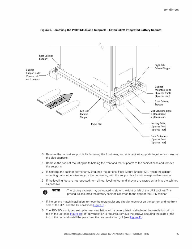
Figure 8. Removing the Pallet Skids and Supports – Eaton 93PM Integrated Battery Cabinet
Rear CabinetSupport
CabinetSupport Bolts(2 places ateach corner)
Left SideCabinetSupport
Pallet Skid
Right SideCabinet Support
CabinetMounting Bolts(4 places front)(4 places rear)
Front CabinetSupport
Skid Mounting Bolts(4 places front)(4 places rear)
Jacking Bolts(2 places front)(2 places rear)
Floor Protectors(2 places front)(2 places rear)
10. Remove the cabinet support bolts fastening the front, rear, and side cabinet supports together and removethe side supports.
11. Remove the cabinet mounting bolts holding the front and rear supports to the cabinet base and removethe supports.
12. If installing the cabinet permanently (requires the optional Floor Mount Bracket Kit), retain the cabinetmounting bolts; otherwise, recycle the bolts along with the support brackets in a responsible manner.
13. If the leveling feet are not retracted, turn all four leveling feet until they are retracted as far into the cabinetas possible.
NOTE The battery cabinet may be located to either the right or left of the UPS cabinet. Thisprocedure assumes the battery cabinet is located to the right of the UPS cabinet.
14. If line-up-and-match installation, remove the rectangular and circular knockout on the bottom and top frontside of the UPS and the IBC–SW (see Figure 9).
15. The IBC–SW is shipped set up for rear ventilation with a cover plate installed over the ventilation grill ontop of the unit (see Figure 10). If top ventilation is required, remove the screws securing the plate at thetop of the unit and install the plate over the rear ventilation grill (see Figure 11).
Installation

26 Eaton 93PM Integrated Battery Cabinet-Small Welded (IBC-SW) Installation Manual 164000639—Rev 03
CAUTIONTo prevent tipping when rolling the cabinet, push the cabinet from the rear whenever possible.
16. Roll the IBC–SW to the line-up-and-match installation location on the side of the UPS cabinet making surethe covers are flush with each other or to the standalone installation location.
17. Lower the cabinet’s leveling feet and using a bubble level, adjust the leveling feet accordingly until thecabinet is level.
18. Locate the top splice bracket shipped with the IBC.
19. Remove the screws along each adjacent cabinet top panel securing the top panels. Retain the hardwarefor later use.
20. Install the top splice bracket between the adjacent cabinet and secure the tie strap with retained hardware.
21. If permanently mounting the IBC (requires the optional Floor Mount Bracket Kit), continue to Step 22;otherwise, proceed to Step 25.
22. Locate the two floor mounting brackets from the Floor Mount Bracket kit.
23. Using the retained cabinet mounting bolts, install the floor mounting brackets to the front and rear of theIBC with the angle facing outward.
24. Secure the cabinet to the floor with customer-supplied hardware.
NOTE In standalone configurations, multiple IBCs are installed adjacent to each other, butseparate from the UPS.
25. If installing more than one IBC, remove the rectangular knockouts on the bottom front sides the IBCs (seeFigure 9) and repeat Steps 1 through 24; otherwise, proceed to Step 26.
Install additional IBCs on the right or left side of the first IBC.
26. Proceed to paragraph 4.3 Installing Power Wiring.
Installation

Eaton 93PM Integrated Battery Cabinet-Small Welded (IBC-SW) Installation Manual 164000639—Rev 03 27
Figure 9. Line-Up-and-Match Wiring Access Locations
Inter-cabinet wiring accessto route interface wiringbetween cabinets.
Inter-cabinet wiring accessknockouts. Remove knockoutsas required to route powerwiring between cabinets.
Left Side View Right Side View
Installation
28 Eaton 93PM Integrated Battery Cabinet-Small Welded (IBC-SW) Installation Manual 164000639—Rev 03
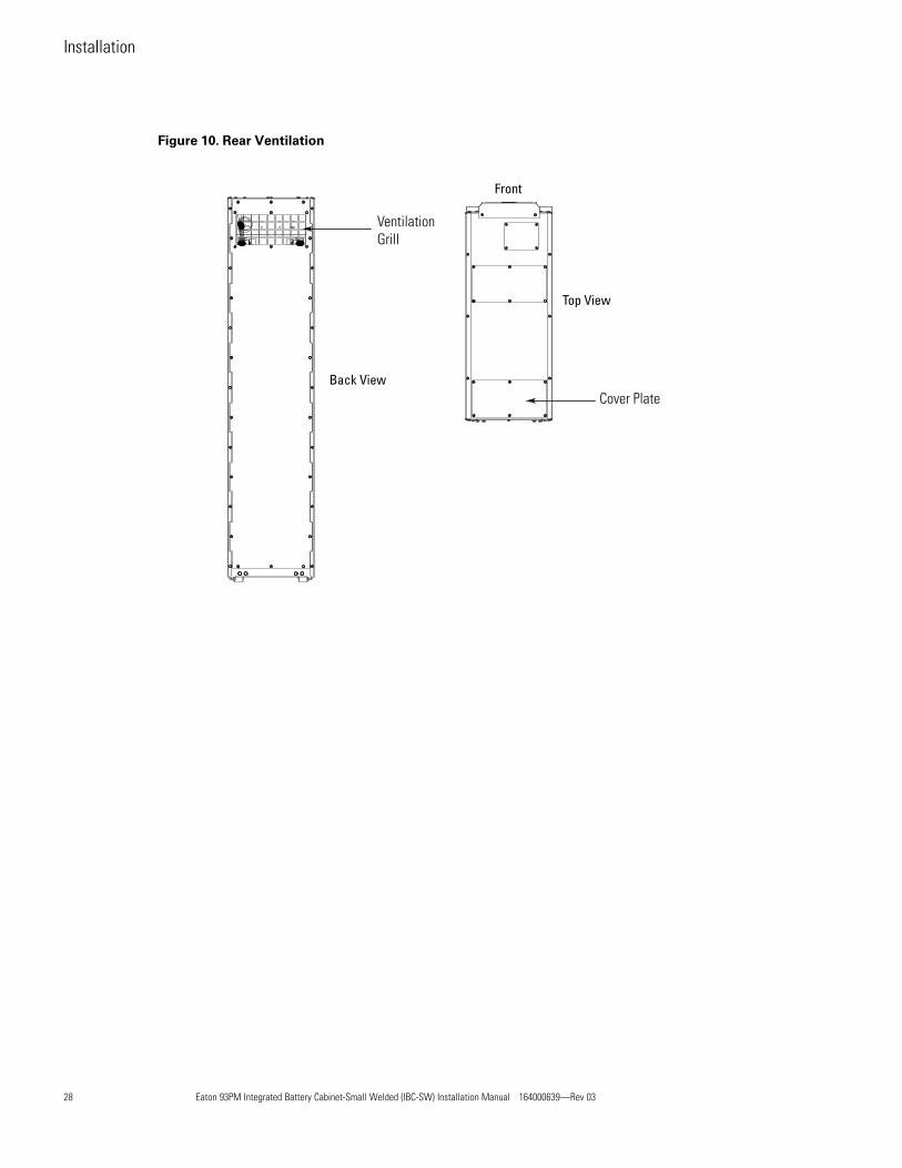
Figure 10. Rear Ventilation
VentilationGrill
Cover Plate
Front
Top View
Back View
Installation

Eaton 93PM Integrated Battery Cabinet-Small Welded (IBC-SW) Installation Manual 164000639—Rev 03 29
Figure 11. Top Ventilation
VentilationCover Plate Grill
Top View
Back View
Front
44..33 IInnssttaalllliinngg PPoowweerr WWiirriinnggIBC–SWs can be installed in a line-up-and-match configuration with the power wiring routed through the IBC–SWs and UPS cabinet or in a standalone configuration with the power wiring routed between the IBC–SWs andthe UPS cabinet using conduit. Use the appropriate procedure for the type of installation being wired.
! IMPORTANTThis product has been evaluated for use with copper wire only. For external wiring, use only 75°C copper wire.
44..33..11 LLiinnee--UUpp--aanndd--MMaattcchh PPoowweerr WWiirriinngg
NOTE 1 Each battery cabinet will be directly connected to the UPS and not daisy-chainedbetween cabinets. All power wiring between the IBC–SWs and the UPS is factorysupplied.
NOTE 2 Up to four IBC–SWs can be installed in a line-up-and-match configuration.
Use this procedure to wire line-up-and-match 93PM Integrated Battery Cabinets to the 93PM UPS cabinet.
To install wiring to connections:
1. Verify the UPS system is turned off and all power sources are removed. Refer to the applicable Eaton93PM UPS Installation and Operation manual, listed in paragraph 1.7 For More Information, for UPSoperating procedures.
Installation

30 Eaton 93PM Integrated Battery Cabinet-Small Welded (IBC-SW) Installation Manual 164000639—Rev 03
2. If not already removed, remove the front cover by loosening the left and right side bottom mounting boltsand remove the two mounting bolts on the top. Lift the cover to disengage the cover from the bottombolts then set the cover to the side in a safe location. Retain the hardware for later use.
3. Remove the screws securing the internal safety shield panel and remove the panel to gain access to thebattery power terminals. Retain the hardware for later use.
NOTE 1 Line-up-and-match positive and negative battery wiring is factory supplied coiled insidethe IBC–SW.
NOTE 2 Ferrules are installed on the ends of the factory supplied wiring. Do not shorten or cutfactory supplied wiring.
4. Route the battery wiring (positive and negative) from the UPS DC Input terminals through the bottom sideinter-cabinet access pass-through (see Figure 9) of the UPS cabinet and IBC–SW to the wiring channel onthe left side of the IBC–SW (see Figure 12). Route the wiring along the wiring channel to the IBC–SW DCOutput terminal block. See Figure 13 for terminal locations. See paragraph3.2.2 IBC–SW Power Wiring Preparation and Table 3 for wiring requirements. Refer to the applicable Eaton93PM UPS Installation and Operation manual listed in paragraph 1.7 For More Information, for UPS cabinetterminal locations.
5. Secure the battery wiring to the wire tie anchors (see Figure 14) using Zip ties.
6. Route the battery cabinet ground wiring from the UPS through the bottom side inter-cabinet access pass-through (see 4.3.1 Line-Up-and-Match Power Wiring) of the UPS cabinet and IBC–SW to the IBC–SWground terminal block. See Figure 13 for terminal location. See paragraph3.2.2 IBC–SW Power Wiring Preparation and Table 3 for wiring requirements.
WARNINGVerify polarity of connections. Risk of personal injury and damage to equipment from arc flash if connectionsare reversed.
7. Connect the positive and negative power wiring to the IBC–SW DC (+) and IBC–SW DC (–) outputterminals. Connect the ground wiring to the IBC–SW ground terminal. See Table 5 for terminationrequirements.
For a detailed view of the IBC–SW terminal block, see Figure 15.
8. Connect the positive, negative, and ground power wiring from the IBC–SW to the UPS cabinet externalbattery input and ground terminals. Refer to the applicable Eaton 93PM UPS Installation and Operationmanual listed in paragraph 1.7 For More Information, for UPS cabinet termination requirements.
NOTE Route the battery wiring between the UPS and subsequent IBC–SWs through thebottom of the adjacent IBC–SW.
9. If installing more than one IBC–SW, repeat Steps 2 through 8 for each IBC–SW, and then proceed toparagraph 4.4 Installing IBC–SW Interface Wiring; otherwise, proceed to paragraph4.4 Installing IBC–SW Interface Wiring.
NOTE The internal battery string is to be connected by an authorized Eaton Customer ServiceEngineer at system startup.
Installation

Eaton 93PM Integrated Battery Cabinet-Small Welded (IBC-SW) Installation Manual 164000639—Rev 03 31
Figure 12. Wiring Channel Location
Wiring Channel
Installation

32 Eaton 93PM Integrated Battery Cabinet-Small Welded (IBC-SW) Installation Manual 164000639—Rev 03
Figure 13. DC Power Terminal Locations – Eaton 93PM IBC–SW
DC Output Terminals+ and –
Ground Terminals
Installation

Eaton 93PM Integrated Battery Cabinet-Small Welded (IBC-SW) Installation Manual 164000639—Rev 03 33
Figure 14. Wire Tie Anchors
Wire TieAnchor
Figure 15. DC Power Terminal Detail – Eaton 93PM IBC–SW
IBC–SW DC (+)Output to UPSPositiveTerminals (+)
IBC–SW DC (–)Output to UPSNegativeTerminals (–)
Wire Tie Anchors
Battery Breaker
Installation

34 Eaton 93PM Integrated Battery Cabinet-Small Welded (IBC-SW) Installation Manual 164000639—Rev 03
44..33..22 SSttaannddaalloonnee PPoowweerr WWiirriinngg
NOTE 1 Each battery cabinet will be directly connected to the UPS and not daisy-chainedbetween cabinets.
NOTE 2 Standalone IBC installations with three or four IBCs require a customer supplied externaltie point and circuit breaker or disconnect between the IBCs and the UPS.
NOTE 3 Up to four IBCs can be installed in a standalone configuration.
NOTE 4 In multiple IBC installations, individual conduit will be run between each battery cabinetand the UPS or disconnect. DO NOT run battery wiring from subsequent IBCs throughthe bottom of the adjacent IBCs.
NOTE 5 Remove the IBC conduit landing plates to drill or punch conduit holes, or removeknockouts in the conduit plate.
Use this procedure to wire standalone 93PM Integrated Battery Cabinets to the 93PM UPS cabinet.
To install wiring to connections:
1. Verify the UPS system is turned off and all power sources are removed. Refer to the applicable Eaton93PM UPS Installation and Operation manual, listed in paragraph 1.7 For More Information, for UPSoperating procedures.
2. If not already removed, remove the front cover by loosening the left and right side bottom mounting boltsand remove the two mounting bolts on the top. Lift the cover to disengage the cover from the bottombolts then set the cover to the side in a safe location. Retain the hardware for later use.
3. Remove the screws securing the internal safety shield panel and remove the panel to gain access to thebattery power terminals. Retain the hardware for later use.
4. If wiring the IBC–SW using the top entry access, continue to Step 5; if using bottom entry access, proceedto Step 13.
5. Top Entry Wiring. Remove the top conduit plate (see Figure 16) from the top of the IBC–SW. Identify allconduit requirements and mark their location. Drill and punch all conduit holes in the top conduit plate priorto mounting on the IBC–SW. Install the conduit plate and install all conduit runs into the plate. Pull thewiring through the conduit into the wiring area.
Note: Power and Interface wiring share the same conduit plate.
6. Route the battery wiring (positive and negative) from the UPS DC Input terminals or DC disconnect tiepoint through top of the IBC–SW to the IBC–SW DC Output terminal block. See Figure 13 for terminallocations. See paragraph 3.2.2 IBC–SW Power Wiring Preparation and Table 4 for wiring requirements.Refer to the applicable Eaton 93PM UPS Installation and Operation manual listed in paragraph1.7 For More Information, for UPS cabinet terminal locations.
7. Route the battery cabinet ground wiring from the UPS through the top of the IBC–SW to the wiringchannel on the left side of the IBC–SW (see Figure 12). Route the wiring along the wiring channel to theIBC–SW ground terminal block. See Figure 13 for terminal location. See paragraph3.2.2 IBC–SW Power Wiring Preparation and Table 4 for wiring requirements.
8. Secure the ground wiring to the wire tie anchors (see Figure 14) using Zip ties.
9. Connect the positive and negative power wiring to the IBC–SW DC (+) and DC (–) output terminals.Connect the ground wiring to the IBC–SW ground terminal. See paragraph3.2.2 IBC–SW Power Wiring Preparation and Table 4 for termination requirements.
10. Connect the positive, negative, and ground DC power wiring from the IBC–SW or disconnect to the UPScabinet battery and ground terminals. Refer to the applicable Eaton 93PM UPS Installation and Operationmanual listed in paragraph 1.7 For More Information, for UPS cabinet termination requirements.
Installation

Eaton 93PM Integrated Battery Cabinet-Small Welded (IBC-SW) Installation Manual 164000639—Rev 03 35
11. Secure the positive, negative, and ground DC power wiring to the wire tie anchors (see Figure 14) usingZip ties.
NOTE If installing more than one IBC–SW, individual conduit will be run between each batterycabinet and the UPS or disconnect. DO NOT run battery wiring from subsequent IBC–SWs through the bottom of the adjacent IBC–SWs.
12. If installing more than one IBC–SW, repeat Steps 2 through 11 for each IBC–SW, and then proceed toparagraph 4.4 Installing IBC–SW Interface Wiring; otherwise, proceed to paragraph4.4 Installing IBC–SW Interface Wiring.
NOTE The internal battery string is to be connected by an authorized Eaton Customer ServiceEngineer at system startup.
13. Bottom Entry Wiring. Remove the bottom conduit plate (see Figure 16) from the inside bottom of theIBC–SW. Identify all conduit requirements and mark their location. Drill and punch all conduit holes in thebottom conduit plate prior to mounting on the IBC–SW. Install the conduit plate and install all conduit runsinto the plate. Pull the wiring through the conduit into the wiring areas.
Note: Power and Interface wiring share the same conduit plate.
14. Route the battery wiring (positive and negative) from the UPS DC Input terminals or DC disconnect tiepoint through the bottom of the IBC–SW to the wiring channel on the left side of the IBC–SW (seeFigure 12). Route the wiring along the wiring channel to the IBC–SW DC Output terminal block. SeeFigure 13 for terminal locations. See paragraph 3.2.2 IBC–SW Power Wiring Preparation and Table 4 forwiring requirements. Refer to the applicable Eaton 93PM UPS Installation and Operation manual listed inparagraph 1.7 For More Information, for UPS cabinet terminal locations.
15. Secure the battery wiring to the wire tie anchors (see Figure 14) using Zip ties.
16. Route the battery cabinet ground wiring from the UPS through the bottom of the IBC–SW to the IBC–SWground terminal block. See Figure 13 for terminal location. See paragraph3.2.2 IBC–SW Power Wiring Preparation and Table 3 for wiring requirements.
17. Connect the positive and negative power wiring to the IBC–SW DC (+) and DC (–) output terminals.Connect the ground wiring to the ground terminal on the IBC–SW. See paragraph3.2.2 IBC–SW Power Wiring Preparation and Table 4 for termination requirements.
For a detailed view of the IBC–SW terminal block, see .
18. Connect the positive, negative, and ground DC power wiring from the IBC–SW or disconnect to the UPScabinet battery and ground terminals. Refer to the applicable Eaton 93PM UPS Installation and Operationmanual listed in paragraph 1.7 For More Information, for UPS cabinet termination requirements.
19. Secure the positive, negative, and ground DC power wiring to the wire tie anchors (see Figure 14) usingZip ties.
NOTE If installing more than one IBC–SW, individual conduit will be run between each batterycabinet and the UPS or disconnect. DO NOT run battery wiring from subsequent IBC–SWs through the bottom of the adjacent IBC–SWs.
20. If installing more than one IBC–SW, repeat Steps 13 through 19 for each IBC–SW, and then proceed toparagraph 4.4 Installing IBC–SW Interface Wiring; otherwise, proceed to paragraph4.4 Installing IBC–SW Interface Wiring.
NOTE The internal battery string is to be connected by an authorized Eaton Customer ServiceEngineer at system startup.
Installation

36 Eaton 93PM Integrated Battery Cabinet-Small Welded (IBC-SW) Installation Manual 164000639—Rev 03
Figure 16. Top and Bottom Entry Conduit and Wire Entry Locations
Access plate forService use only.
**Not to be used forconduit routing**
Top Entry ConduitLanding for DC Output /Interface wiring(Remove panel to drillor punch conduit holes.)
Bottom Entry ConduitLanding for DC Output /Interface wiring(Remove panel to drillor punch conduit holes.)
Top View Bottom View
Front Front
44..44 IInnssttaalllliinngg IIBBCC––SSWW IInntteerrffaaccee WWiirriinnggIBC–SWs can be installed in a line-up-and-match configuration with the interface wiring routed through theIBC–SWs and UPS cabinet or in a standalone configuration with the interface wiring routed between the IBC–SWs and the UPS cabinet using conduit.
44..44..11 IInnssttaalllliinngg BBaatttteerryy DDeetteecctt IInntteerrffaaccee CCoonnnneeccttiioonnss
NOTE 1 Disconnect terminal block plug from terminal block to wire plug.
NOTE 2 If the inter-cabinet wiring access pass-through is not used to install the battery detectinterface wiring connections, conduit must be installed between the battery cabinet andthe UPS cabinet.
To install wiring:
1. If wiring the IBC–SW battery detect interface terminals using line-up-and-match wiring using the inter-cabinet wiring access pass-through (see Figure 9) continue to Step 2; if wiring the IBC–SW battery detectinterface terminals using the top entry access, proceed to Step 5; if wiring the IBC–SW battery detectinterface terminals using the bottom entry access, proceed to Step 8.
NOTE In multiple IBC–SW installations, route the battery interface wiring between IBC–SWsthrough the top of the adjacent IBC–SW using the top side inter-cabinet access pass-through (see Figure 9).
Installation
Eaton 93PM Integrated Battery Cabinet-Small Welded (IBC-SW) Installation Manual 164000639—Rev 03 37
2. Line-Up-and-Match Wiring. Route the battery detect interface wiring from the UPS battery detectinterface terminals through the top inter-cabinet access pass-through (see Figure 9) of the UPS cabinet andIBC–SW to the IBC–SW battery interface terminal block TB2. See Figure 17 for terminal locations. Seeparagraph 3.2.3 IBC–SW Interface Wiring Preparation, Table 7, and Figure 18 for wiring and terminationrequirements. Refer to the applicable Eaton 93PM UPS Installation and Operation manual listed inparagraph 1.7 For More Information, for UPS cabinet terminal locations.
3. Proceed to Step 10.
4. Top Entry Wiring. Remove the top conduit plate (see Figure 16) from the top of the IBC–SW. Identify allconduit requirements and mark their location. Drill and punch all conduit holes in the top conduit plate priorto mounting on the IBC–SW. Install the conduit plate and install all conduit runs into the plate. Pull thewiring through the conduit into the wiring area.
NOTE In multiple IBC–SW installations, route the battery interface wiring between IBC–SWsthrough the top of the adjacent IBC–SW using the top side inter-cabinet access pass-through (see Figure 9).
5. Route the battery detect interface wiring from the UPS battery detect interface terminals through top ofthe IBC–SW to the IBC–SW battery interface terminal block TB2. See Figure 17 for terminal locations. Seeparagraph 3.2.3 IBC–SW Interface Wiring Preparation, Table 7, and Figure 18 for wiring and terminationrequirements. Refer to the applicable Eaton 93PM UPS Installation and Operation manual listed inparagraph 1.7 For More Information, for UPS cabinet terminal locations.
6. Proceed to Step 10.
7. Bottom Entry Wiring. Remove the bottom conduit plate (see Figure 16) from the inside bottom of theIBC–SW. Identify all conduit requirements and mark their location. Drill and punch all conduit holes in thebottom conduit plate prior to mounting on the IBC–SW. Install the conduit plate and install all conduit runsinto the plate. Pull the wiring through the conduit into the wiring areas.
NOTE In multiple IBC–SW installations, route the battery interface wiring between IBC–SWsthrough the top of the adjacent IBC–SW using the top side inter-cabinet access pass-through (see Figure 9).
8. Route the battery detect interface wiring from the UPS battery detect interface terminals through thebottom of the IBC–SW to the wiring channel on the left side of the IBC–SW (see Figure 12). Route thewiring along the wiring channel to the IBC–SW battery interface terminal block TB2. See Figure 17 forterminal locations. See paragraph 3.2.3 IBC–SW Interface Wiring Preparation, Table 7, and Figure 18 forwiring and termination requirements. Refer to the applicable Eaton 93PM UPS Installation and Operationmanual listed in paragraph 1.7 For More Information, for UPS cabinet terminal locations.
9. Secure the interface wiring to the wire tie anchors (see Figure 14) using Zip ties.
10. Connect the battery detect interface wiring to the IBC–SW battery detect interface terminals. Seeparagraph 3.2.3 IBC–SW Interface Wiring Preparation and Table 8 for termination requirements.
For a detailed view of the IBC–SW terminal block, see Figure 19.
11. Connect the battery detect interface wiring to the UPS battery detect interface terminals. Refer to theapplicable Eaton 93PM UPS Installation and Operation manual listed in paragraph1.7 For More Information, for UPS cabinet termination requirements.
NOTE In the following step, if the safety shield cannot be reinstalled because of misalignment,use the leveling feet to realign the cabinet.
12. Reinstall the internal safety shield panel removed in Step 3 of paragraph4.3.1 Line-Up-and-Match Power Wiring.
Installation

38 Eaton 93PM Integrated Battery Cabinet-Small Welded (IBC-SW) Installation Manual 164000639—Rev 03
13. Install the front cover (previously removed) by carefully lowering the cover onto the bottom mountingbolts. Secure the top of the cover with the two retained mounting bolts and tighten the bottom bolts.
14. Once the battery cabinets are installed and wired, return to the applicable Eaton 93PM UPS Installation andOperation manual, listed in paragraph 1.7 For More Information, to complete the UPS wiring.
Figure 17. Interface Terminal Locations – Eaton 93PM IBC–SW
InterfaceTerminal TB2
Table 7. IBC TB2 Interface Connections
TerminalTB2 Name Description
10 Thermal Sensor Contact used to signal a battery temperature out of specification andto turn off the battery charger to prevent thermal runaway.
Installation

Eaton 93PM Integrated Battery Cabinet-Small Welded (IBC-SW) Installation Manual 164000639—Rev 03 39
Table 7. IBC TB2 Interface Connections (Continued)
TerminalTB2 Name Description
9 Thermal Sensor Return
8 Not Used
7 To Next IBC TB2-2 Contacts used to open battery breaker or disconnect on second,third, and fourth IBCs.6 To Next IBC TB2-1
5 Battery Detect Common Contacts used to indicate whether UPS battery breaker is open orclosed.4 Battery Detect
3 Not Used
2 48 Vdc Battery Shunt Trip –Contacts used to open battery breaker or disconnect.
1 48 Vdc Battery Shunt Trip +
Table 8. IBC TB2 Interface Wiring Terminal Block Terminations
Terminal FunctionSize of PressureTermination
TighteningTorque Nm (lb
in)TypeScrew Comments
Shunt Trip #26–#16 0.4 (3.5) - 0.8 (7.1) Slotted Use #18 AWG twisted-pair wires for each inputand return or common. Strip wire insulationback 10 millimeters to wire terminal blocks.Use wire rated for 600V and Class 1 wiringmethods.
Battery Detect #26–#16 0.4 (3.5) - 0.8 (7.1) Slotted Use #18 AWG twisted-pair wires for each inputand return or common. Strip wire insulationback 10 millimeters to wire terminal blocks.
Thermal Sensor #26–#16 0.4 (3.5) - 0.8 (7.1) Slotted Use #18 AWG twisted-pair wires for each inputand return or common. Strip wire insulationback 10 millimeters to wire terminal blocks.
Installation

40 Eaton 93PM Integrated Battery Cabinet-Small Welded (IBC-SW) Installation Manual 164000639—Rev 03
Figure 18. Shunt Trip, Battery Detect, and Thermal Sensor Wiring
UPS
ShuntTrip TB
1
2
3
4
IBC1
TB2
1
2
3
4
5
6
7
8
9
10
IBC2
TB2
1
2
3
4
5
6
7
8
9
10
IBC3
TB2
1
2
3
4
5
6
7
8
9
10
IBC4
TB2
1
2
3
4
5
6
7
8
9
10
ShuntTrip
BatteryDetect
ThermalSensor
UPS
BuildingAlarm TB
5
6
7
8
1
2
3
4
9
10
NOTE 1 IBC–SW1 is closest to the UPS.
NOTE 2 The IBC–SW shunt trip is wired in parallel. The IBC–SW battery detect is wired in series.
NOTE 3 If less than four IBC–SWs are installed, the last IBC–SW TB2-5 connection returns toUPS Battery Detect Building Alarm terminal.
NOTE 4 Because of the battery shunt trip wiring route in the 93PM UPS cabinet, the wiring fromthe IBC–SW battery shunt trip terminals to the UPS must use wire rated for 600V andClass 1 wiring methods.
NOTE 5 The Thermal Sensor is optional. If not installed, terminals TB2-9, and TB2-10 are notused.
Installation
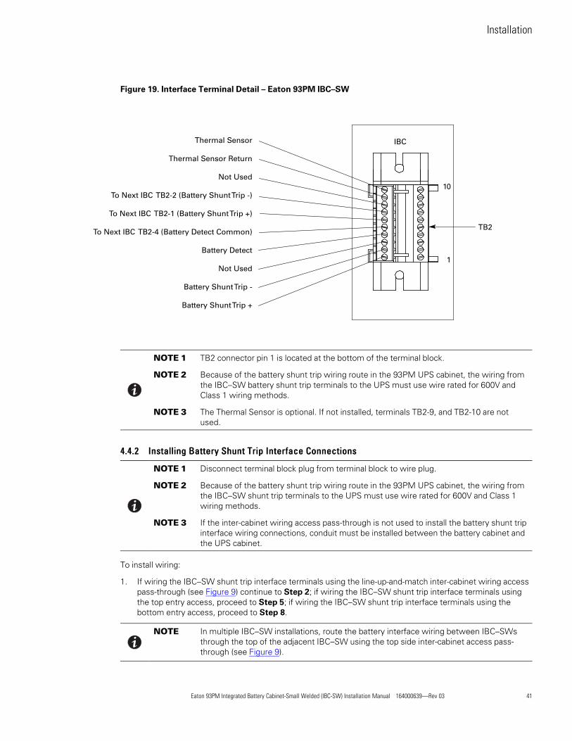
Eaton 93PM Integrated Battery Cabinet-Small Welded (IBC-SW) Installation Manual 164000639—Rev 03 41
Figure 19. Interface Terminal Detail – Eaton 93PM IBC–SW
Thermal Sensor
Thermal Sensor Return
Not Used
To Next IBC TB2-2 (Battery Shunt Trip -)
To Next IBC TB2-1 (Battery Shunt Trip +)
To Next IBC TB2-4 (Battery Detect Common)
Battery Detect
Not Used
Battery Shunt Trip -
Battery Shunt Trip +
IBC
TB2
10
1
NOTE 1 TB2 connector pin 1 is located at the bottom of the terminal block.
NOTE 2 Because of the battery shunt trip wiring route in the 93PM UPS cabinet, the wiring fromthe IBC–SW battery shunt trip terminals to the UPS must use wire rated for 600V andClass 1 wiring methods.
NOTE 3 The Thermal Sensor is optional. If not installed, terminals TB2-9, and TB2-10 are notused.
44..44..22 IInnssttaalllliinngg BBaatttteerryy SShhuunntt TTrriipp IInntteerrffaaccee CCoonnnneeccttiioonnss
NOTE 1 Disconnect terminal block plug from terminal block to wire plug.
NOTE 2 Because of the battery shunt trip wiring route in the 93PM UPS cabinet, the wiring fromthe IBC–SW shunt trip terminals to the UPS must use wire rated for 600V and Class 1wiring methods.
NOTE 3 If the inter-cabinet wiring access pass-through is not used to install the battery shunt tripinterface wiring connections, conduit must be installed between the battery cabinet andthe UPS cabinet.
To install wiring:
1. If wiring the IBC–SW shunt trip interface terminals using the line-up-and-match inter-cabinet wiring accesspass-through (see Figure 9) continue to Step 2; if wiring the IBC–SW shunt trip interface terminals usingthe top entry access, proceed to Step 5; if wiring the IBC–SW shunt trip interface terminals using thebottom entry access, proceed to Step 8.
NOTE In multiple IBC–SW installations, route the battery interface wiring between IBC–SWsthrough the top of the adjacent IBC–SW using the top side inter-cabinet access pass-through (see Figure 9).
Installation

42 Eaton 93PM Integrated Battery Cabinet-Small Welded (IBC-SW) Installation Manual 164000639—Rev 03
2. Line-Up-and-Match Wiring. Route the battery shunt trip interface wiring from the UPS battery shunt tripinterface terminals through the bottom inter-cabinet access pass-through (see Figure 9) of the UPS cabinetand IBC–SW to the wiring channel on the left side of the IBC–SW (see Figure 12). Route the wiring alongthe wiring channel to the IBC–SW battery interface terminal block TB2. See Figure 17 for terminallocations. See paragraph 3.2.3 IBC–SW Interface Wiring Preparation, Table 7, and Figure 18 for wiring andtermination requirements. Refer to the applicable Eaton 93PM UPS Installation and Operation manuallisted in paragraph 1.7 For More Information, for UPS cabinet terminal locations.
3. Secure the interface wiring to the wire tie anchors (see Figure 14) using Zip ties.
4. Proceed to Step 11.
5. Top Entry Wiring. Remove the top conduit plate (see Figure 16) from the top of the IBC–SW. Identify allconduit requirements and mark their location. Drill and punch all conduit holes in the top conduit plate priorto mounting on the IBC–SW. Install the conduit plate and install all conduit runs into the plate. Pull thewiring through the conduit into the wiring area.
NOTE In multiple IBC–SW installations, route the battery interface wiring between IBC–SWsthrough the top of the adjacent IBC–SW using the top side inter-cabinet access pass-through (see Figure 9).
6. Route the battery shunt trip interface wiring from the UPS battery shunt trip interface terminals throughtop of the IBC–SW to the IBC–SW battery interface terminal block TB2. See Figure 17 for terminallocations. See paragraph 3.2.3 IBC–SW Interface Wiring Preparation, Table 7, and Figure 18 for wiring andtermination requirements. Refer to the applicable Eaton 93PM UPS Installation and Operation manuallisted in paragraph 1.7 For More Information, for UPS cabinet terminal locations.
7. Proceed to Step 11.
8. Bottom Entry Wiring. Remove the bottom conduit plate (see Figure 16) from the inside bottom of theIBC–SW. Identify all conduit requirements and mark their location. Drill and punch all conduit holes in thebottom conduit plate prior to mounting on the IBC–SW. Install the conduit plate and install all conduit runsinto the plate. Pull the wiring through the conduit into the wiring areas.
NOTE In multiple IBC–SW installations, route the battery interface wiring between IBC–SWsthrough the top of the adjacent IBC–SW using the top side inter-cabinet access pass-through (see Figure 9).
9. Route the battery shunt trip interface wiring from the UPS battery shunt trip interface terminals throughthe bottom of the IBC–SW to the wiring channel on the left side of the IBC–SW (see Figure 12). Route thewiring along the wiring channel to the IBC–SW battery interface terminal block TB2. See Figure 17 forterminal locations. See paragraph 3.2.3 IBC–SW Interface Wiring Preparation, Table 7, and Figure 18 forwiring and termination requirements. Refer to the applicable Eaton 93PM UPS Installation and Operationmanual listed in paragraph 1.7 For More Information, for UPS cabinet terminal locations.
10. Secure the interface wiring to the wire tie anchors (see Figure 14) using Zip ties.
11. Connect the battery shunt trip interface wiring to the IBC–SW battery shunt trip interface terminals. Seeparagraph 3.2.3 IBC–SW Interface Wiring Preparation and Table 8 for termination requirements.
For a detailed view of the IBC–SW terminal block, see Figure 19.
12. Connect the battery shunt trip interface wiring to the UPS battery shunt trip interface terminals. Refer tothe applicable Eaton 93PM UPS Installation and Operation manual listed in paragraph1.7 For More Information, for UPS cabinet termination requirements.
NOTE In the following step, if the safety shield cannot be reinstalled because of misalignment,use the leveling feet to realign the cabinet.
Installation

Eaton 93PM Integrated Battery Cabinet-Small Welded (IBC-SW) Installation Manual 164000639—Rev 03 43
13. Reinstall the internal safety shield panel removed in Step 3 of paragraph4.3.1 Line-Up-and-Match Power Wiring.
14. Install the front cover (previously removed) by carefully lowering the cover onto the bottom mountingbolts. Secure the top of the cover with the two retained mounting bolts and tighten the bottom bolts.
15. Once the battery cabinets are installed and wired, return to the applicable Eaton 93PM UPS Installation andOperation manual, listed in paragraph 1.7 For More Information, to complete the UPS wiring.
44..44..33 IInnssttaalllliinngg TThheerrmmaall SSeennssoorr IInntteerrffaaccee CCoonnnneeccttiioonnss
NOTE 1 The UPS thermal sensor signal uses an UPS building alarm input to indicate a thermaltrip condition and to turn off the battery charger.
NOTE 2 Any pair of unused building alarm terminals may be used for the thermal sensorconnections.
NOTE 3 Program the thermal sensor building alarm to read battery thermal trip and for normallyopen contacts.
NOTE 4 Disconnect terminal block plug from terminal block to wire plug.
NOTE 5 If the inter-cabinet wiring access pass-through is not used to install the thermal sensorinterface wiring connections, conduit must be installed between the battery cabinet andthe UPS cabinet.
To install wiring:
1. If wiring the IBC–SW thermal sensor interface terminals using line-up-and-match wiring using the inter-cabinet wiring access pass-through (see Figure 9) continue to Step 2; if wiring the IBC–SW thermal sensorinterface terminals using the top entry access, proceed to Step 4; if wiring the IBC–SW thermal sensorinterface terminals using the bottom entry access, proceed to Step 7.
NOTE In multiple IBC–SW installations, route the battery interface wiring between IBC–SWsthrough the top of the adjacent IBC–SW using the top side inter-cabinet access pass-through (see Figure 9).
2. Line-Up-and-Match Wiring. Route the thermal sensor interface wiring from the UPS thermal sensor(building alarm) interface terminals through the top inter-cabinet access pass-through (see Figure 9) of theUPS cabinet and IBC–SW to the IBC–SW battery interface terminal block TB2. See Figure 17 for terminallocations. See paragraph 3.2.3 IBC–SW Interface Wiring Preparation, Table 7, and Figure 18 for wiring andtermination requirements. Refer to the applicable Eaton 93PM UPS Installation and Operation manuallisted in paragraph 1.7 For More Information, for UPS cabinet terminal locations.
3. Proceed to Step 10.
4. Top Entry Wiring. Remove the top conduit plate (see Figure 16) from the top of the IBC–SW. Identify allconduit requirements and mark their location. Drill and punch all conduit holes in the top conduit plate priorto mounting on the IBC–SW. Install the conduit plate and install all conduit runs into the plate. Pull thewiring through the conduit into the wiring area.
NOTE In multiple IBC–SW installations, route the battery interface wiring between IBC–SWsthrough the top of the adjacent IBC–SW using the top side inter-cabinet access pass-through (see Figure 9).
5. Route the thermal sensor interface wiring from the UPS thermal sensor (building alarm) interface terminalsthrough the top of the IBC–SW and the top IBC–SW inter-cabinet wiring access pass-through (seeFigure 9) to the IBC–SW battery interface terminal block TB2. See Figure 17 for terminal locations. Seeparagraph 3.2.3 IBC–SW Interface Wiring Preparation, Table 7, and Figure 18 for wiring and termination
Installation
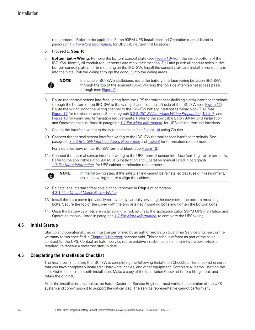
44 Eaton 93PM Integrated Battery Cabinet-Small Welded (IBC-SW) Installation Manual 164000639—Rev 03
requirements. Refer to the applicable Eaton 93PM UPS Installation and Operation manual listed inparagraph 1.7 For More Information, for UPS cabinet terminal locations.
6. Proceed to Step 10.
7. Bottom Entry Wiring. Remove the bottom conduit plate (see Figure 16) from the inside bottom of theIBC–SW. Identify all conduit requirements and mark their location. Drill and punch all conduit holes in thebottom conduit plate prior to mounting on the IBC–SW. Install the conduit plate and install all conduit runsinto the plate. Pull the wiring through the conduit into the wiring areas.
NOTE In multiple IBC–SW installations, route the battery interface wiring between IBC–SWsthrough the top of the adjacent IBC–SW using the top side inter-cabinet access pass-through (see Figure 9).
8. Route the thermal sensor interface wiring from the UPS thermal sensor (building alarm) interface terminalsthrough the bottom of the IBC–SW to the wiring channel on the left side of the IBC–SW (see Figure 12).Route the wiring along the wiring channel to the IBC–SW battery interface terminal block TB2. SeeFigure 17 for terminal locations. See paragraph 3.2.3 IBC–SW Interface Wiring Preparation, Table 7, andFigure 18 for wiring and termination requirements. Refer to the applicable Eaton 93PM UPS Installationand Operation manual listed in paragraph 1.7 For More Information, for UPS cabinet terminal locations.
9. Secure the interface wiring to the wire tie anchors (see Figure 14) using Zip ties.
10. Connect the thermal sensor interface wiring to the IBC–SW thermal sensor interface terminals. Seeparagraph 3.2.3 IBC–SW Interface Wiring Preparation and Table 8 for termination requirements.
For a detailed view of the IBC–SW terminal block, see Figure 19.
11. Connect the thermal sensor interface wiring to the UPS thermal sensor interface (building alarm) terminals.Refer to the applicable Eaton 93PM UPS Installation and Operation manual listed in paragraph1.7 For More Information, for UPS cabinet termination requirements.
NOTE In the following step, if the safety shield cannot be reinstalled because of misalignment,use the leveling feet to realign the cabinet.
12. Reinstall the internal safety shield panel removed in Step 3 of paragraph4.3.1 Line-Up-and-Match Power Wiring.
13. Install the front cover (previously removed) by carefully lowering the cover onto the bottom mountingbolts. Secure the top of the cover with the two retained mounting bolts and tighten the bottom bolts.
14. Once the battery cabinets are installed and wired, return to the applicable Eaton 93PM UPS Installation andOperation manual, listed in paragraph 1.7 For More Information, to complete the UPS wiring.
44..55 IInniittiiaall SSttaarrttuuppStartup and operational checks must be performed by an authorized Eaton Customer Service Engineer, or thewarranty terms specified in Chapter 8 Warranty become void. This service is offered as part of the salescontract for the UPS. Contact an Eaton service representative in advance (a minimum two-week notice isrequired) to reserve a preferred startup date.
44..66 CCoommpplleettiinngg tthhee IInnssttaallllaattiioonn CChheecckklliissttThe final step in installing the IBC–SW is completing the following Installation Checklist. This checklist ensuresthat you have completely installed all hardware, cables, and other equipment. Complete all items listed on thechecklist to ensure a smooth installation. Make a copy of the Installation Checklist before filling it out, andretain the original.
After the installation is complete, an Eaton Customer Service Engineer must verify the operation of the UPSsystem and commission it to support the critical load. The service representative cannot perform any
Installation

Eaton 93PM Integrated Battery Cabinet-Small Welded (IBC-SW) Installation Manual 164000639—Rev 03 45
installation tasks other than verifying software and operating setup parameters. Service personnel may requesta copy of the completed Installation Checklist to verify all applicable equipment installations have beencompleted.
NOTE The Installation Checklist MUST be completed prior to starting the UPS system for thefirst time.
Installation Checklist
o All IBCs are the same model and rating.
o All packing materials and restraints have been removed from each cabinet.
o The IBCs are installed on a level floor suitable for computer or electronic equipment.
o The IBCs are placed in their installed location
o All conduits and cables are properly routed between the IBCs and the UPS.
o All power cables are properly sized and terminated.
o A ground conductor is properly installed.
o Battery cables are terminated on the positive and negative terminals in the UPS cabinet.
o Battery Shunt trip and Battery Detect signal wiring is connected from the battery breaker to the UPS.
o All internal safety shields are installed.
o Air conditioning equipment is installed and operating correctly.
o The area around the UPS system is clean and dust-free.
o Adequate workspace exists around the IBC and other cabinets.
o Adequate lighting is provided around all IBC and UPS equipment.
o A 120 Vac service outlet is located within 7.5 meters (25 feet) of the IBC and UPS equipment.
o Startup and operational checks are performed by an authorized Eaton Customer Service Engineer.
o Visit www.eaton.com/pq/register to register your new Eaton UPS / Eaton UPS Accessory.
Installation

46 Eaton 93PM Integrated Battery Cabinet-Small Welded (IBC-SW) Installation Manual 164000639—Rev 03
Notes
_________________________________________________________________________
_________________________________________________________________________
_________________________________________________________________________
_________________________________________________________________________
_________________________________________________________________________
_________________________________________________________________________
_________________________________________________________________________
_________________________________________________________________________
_________________________________________________________________________
_________________________________________________________________________
_________________________________________________________________________
_________________________________________________________________________
_________________________________________________________________________
_________________________________________________________________________
_________________________________________________________________________
Installation

Eaton 93PM Integrated Battery Cabinet-Small Welded (IBC-SW) Installation Manual 164000639—Rev 03 47
CChhaapptteerr 55 OOnneelliinneess aanndd SScchheemmaattiiccss
55..11 PPoowweerr OOnneelliinneessFigure 20 through Figure 22 show the 93PM UPS and 93PM Integrated Battery Cabinet intercabinet powerconnection onelines.
Figure 20. 93PM Integrated Battery Cabinet Line-Up-and-Match Power Oneline
UPS Cabinet Battery Cabinet 1 Battery Cabinet 2 Battery Cabinet 3 Battery Cabinet 4
Internal Internal Internal InternalBattery Battery Battery BatteryBreaker Breaker Breaker Breaker
Four Battery Cabinets Maximum
NOTE Three and four battery cabinet wiring assumes using factory supplied wiring and onewire per pole.
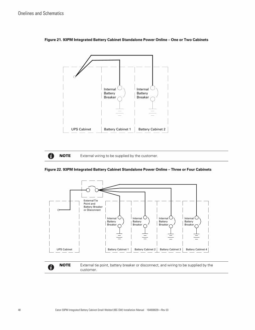
48 Eaton 93PM Integrated Battery Cabinet-Small Welded (IBC-SW) Installation Manual 164000639—Rev 03
Figure 21. 93PM Integrated Battery Cabinet Standalone Power Online – One or Two Cabinets
Internal Internal Battery Battery Breaker Breaker
UPS Cabinet Battery Cabinet 1 Battery Cabinet 2
NOTE External wiring to be supplied by the customer.
Figure 22. 93PM Integrated Battery Cabinet Standalone Power Online – Three or Four Cabinets
External TiePoint and Battery Breakeror Disconnect
UPS Cabinet Battery Cabinet 1 Battery Cabinet 2 Battery Cabinet 3 Battery Cabinet 4
Internal Internal Internal InternalBattery Battery Battery BatteryBreaker Breaker Breaker Breaker
NOTE External tie point, battery breaker or disconnect, and wiring to be supplied by thecustomer.
Onelines and Schematics

Eaton 93PM Integrated Battery Cabinet-Small Welded (IBC-SW) Installation Manual 164000639—Rev 03 49
55..22 IInntteerrffaaccee OOnneelliinneessFigure 23 shows the 93PM UPS and 93PM Integrated Battery Cabinet intercabinet interface connectiononelines.
Figure 23. 93PM Integrated Battery Cabinet Interface Oneline
BatteryCabinet 1
(First)
ST
BatteryCabinet 2(Middle)
ST
BatteryCabinet 4
(Last)
ST
BatteryCabinet 3(Middle)
ST
Multiple Battery Cabinets
48 Vdc
NOTE Battery Detect and DC Shunt Trip wiring should be a minimum of 18 AWG.
UPS Shunt Trip TB
BatteryCabinet
ST
Single Battery Cabinet
Battery Detect
Battery Detect Common
48 Vdc Battery Shunt Trip +
48 Vdc Battery Shunt Trip –
1
2
48 Vdc
TB2 TB2 TB2 TB2
UPS BuildingAlarm TB
1
2
TB2
UPS Shunt Trip TB
Battery Detect
Battery Detect Common
48 Vdc Battery Shunt Trip +
48 Vdc Battery Shunt Trip –
1
2
UPS BuildingAlarm TB
1
2
55..33 SScchheemmaattiiccssFigure 24 and Figure 25 show the 93PM Integrated Battery Cabinet schematics.
Onelines and Schematics

50 Eaton 93PM Integrated Battery Cabinet-Small Welded (IBC-SW) Installation Manual 164000639—Rev 03
Figure 24. 93PM Integrated Battery Cabinet Schematic
Onelines and Schematics

Eaton 93PM Integrated Battery Cabinet-Small Welded (IBC-SW) Installation Manual 164000639—Rev 03 51
Figure 25. 93PM Integrated Battery Cabinet — Battery String Detail Schematic
Onelines and Schematics

52 Eaton 93PM Integrated Battery Cabinet-Small Welded (IBC-SW) Installation Manual 164000639—Rev 03
Onelines and Schematics

Eaton 93PM Integrated Battery Cabinet-Small Welded (IBC-SW) Installation Manual 164000639—Rev 03 53
CChhaapptteerr 66 MMaaiinntteennaannccee
The components inside the IBC are secured to a sturdy metal frame. All repairable parts and assemblies arelocated for easy removal, with very little disassembly. This design allows authorized service personnel toperform routine maintenance and servicing quickly.
You must schedule periodic performance checks of the UPS system to keep it running properly. Regularroutine checks of operation and system parameters enable your system to function efficiently for many trouble-free years.
66..11 IImmppoorrttaanntt SSaaffeettyy IInnssttrruuccttiioonnssRemember that your UPS system is designed to supply power EVENWHEN DISCONNECTED FROM THEUTILITY POWER.
WARNING
• No user serviceable components.
• Servicing and maintenance should be performed by qualified service personnel only.
• LETHAL VOLTAGE PRESENT. This unit should not be operated with the cabinet doors open or protectivepanels removed. Do not make any assumptions about the electrical state of any cabinet in the UPSsystem.
66..22 PPeerrffoorrmmiinngg PPrreevveennttiivvee MMaaiinntteennaanncceeThe UPS system requires very little preventive maintenance. However, the system should be inspectedperiodically to verify that the units are operating normally. Record maintenance results and any correctiveactions in a suitable log.
66..22..11 DDAAIILLYY MMaaiinntteennaannccee
Perform the following steps daily:
1. Check the area surrounding the UPS system. Ensure the area is not cluttered, allowing free accessto the unit.
2. Ensure the air intakes on the Accessory cabinets are not blocked.
3. Ensure the operating environment is within the parameters specified in paragraph 3.2.1 Environmentaland Installation Considerations and Chapter 7 Product Specifications.
66..22..22 PPEERRIIOODDIICC MMaaiinntteennaannccee
Periodic inspections of the IBC should be made to determine if components, wiring, and connections exhibitevidence of overheating. Particular attention should be given to the compression lug connections. Maintenanceprocedures should specify that the compression lug connections be retorqued to values listed in this manual.
66..22..33 AANNNNUUAALL MMaaiinntteennaannccee
Annual preventive maintenance should be performed only by authorized service personnel familiar withmaintenance and servicing of the UPS system. Contact an Eaton service representative for more informationabout service offerings.
66..22..44 BBAATTTTEERRYY MMaaiinntteennaannccee
Contact an Eaton service representative for battery maintenance. Battery replacement and maintenance shouldbe performed only by authorized service personnel.

54 Eaton 93PM Integrated Battery Cabinet-Small Welded (IBC-SW) Installation Manual 164000639—Rev 03
66..22..55 BBAATTTTEERRYY SShheellff LLiiffee
The shelf life for the batteries installed in the IBC is 12 months from the date code on the battery. The rechargedate is also stated on a label inside the IBC.
CAUTIONFailure to recharge the batteries before the expiration of the shelf life will result in reduced discharge time,shorter float service life, and will void the warranty.
66..33 RReeccyycclliinngg tthhee UUsseedd BBaatttteerriieessContact your local recycling or hazardous waste center for information on proper disposal of the used Valve-Regulated Lead-Acid (VRLA) batteries.
WARNING
• Do not dispose of the battery or batteries in a fire. Batteries may explode. Proper disposal of batteries isrequired. Refer to your local codes for disposal requirements.
• Do not open or mutilate the battery or batteries. Released electrolyte is harmful to the skin and eyes. Itmay be toxic.
• A battery can cause electrical shock, burn from high short-circuit current, or fire. Observe properprecautions.
ATTENTION!
• Une batterie peut prêsenter un risque de choc êlectrique, de brulure, ou d'incendie. Suivre les précautionsqui s'imposent.
• Pour le remplacement, utiliser le même nombre et modéle des batteries.
• L'élimination des batteries est règlementée. Consulter les codes locaux à cet effet.
CAUTION
Do not discard the UPS or the UPS batteries in the trash. This product contains sealed, lead-acid batteries andmust be disposed of properly. For more information, contact your local recycling/reuse or hazardous wastecenter.
Special SymbolsThe following are examples of symbols used on the UPS or accessories to alert you to importantinformation:
RISK OF ELECTRIC SHOCK - Observe the warning associated with the risk ofelectric shock symbol.
CAUTION: REFER TO OPERATOR'S MANUAL - Refer to your operator's manual foradditional information, such as important operating and maintenanceinstructions.
This symbol indicates that you should not discard the UPS or the UPS batteriesin the trash. This product contains sealed, lead‐acid batteries and must bedisposed of properly. For more information, contact your local recycling/reuse orhazardous waste center.
This symbol indicates that you should not discard waste electrical or electronicequipment (WEEE) in the trash. For proper disposal, contact your localrecycling/reuse or hazardous waste center.
Eaton, Powerware, and BladeUPS are registered trademarks of Eaton Corporation or its subsidiaries and affiliates.Phillips and Pozidriv are registered trademarks of Phillips Screw Company.
�Copyright 2008–2010 Eaton Corporation, Raleigh, NC, USA. All rights reserved. No part of this document may bereproduced in any way without the express written approval of Eaton Corporation.
CAUTION
Do not discard waste electrical or electronic equipment (WEEE) in the trash. For proper disposal, contact yourlocal recycling/reuse or hazardous waste center.
66..44 MMaaiinntteennaannccee TTrraaiinniinnggA basic training course, available from Eaton, gives you a competent working knowledge of the UPS systemoperation and teaches you how to perform first level corrective maintenance. For more information abouttraining and other services, contact the Customer Reliability Center (see paragraph 1.8 Getting Help).
Maintenance

Eaton 93PM Integrated Battery Cabinet-Small Welded (IBC-SW) Installation Manual 164000639—Rev 03 55
CChhaapptteerr 77 PPrroodduucctt SSppeecciiffiiccaattiioonnss
This section provides the following specifications:
• Model Numbers
• Battery specifications
• Environmental and safety specifications
77..11 MMooddeellssThe Integrated Battery Cabinet – Small Welded (IBC–SW) is available in two models to meet the needs of theEaton 93PM UPS product line.
Integrated BatteryCabinet (IBC)
DC VoltageOutput
(Nominal)
BatteryNameplateCurrent Description
Eaton 93PM IntegratedBattery Cabinet-Small
Welded
432V 165A
IBC for:Eaton 93PM (400/480V) 50 kW UPSEaton 93PM (400/480V) 100 kW UPSEaton 93PM (400/480V) 150 kW UPSEaton 93PM (400/480V) 200 kW UPS
480V 158A
IBC for:Eaton 93PM-L (208V) 60 kW UPSEaton 93PM-L (208V) 120 kW UPSEaton 93PM-L (208V) 160 kW UPSEaton 93PM-L (208V) 200 kW UPSandEaton 93PM (400/480V) 50 kW UPSEaton 93PM (400/480V) 100 kW UPSEaton 93PM (400/480V) 150 kW UPSEaton 93PM (400/480V) 200 kW UPS
77..22 SSppeecciiffiiccaattiioonnssThe following sections detail the battery specifications, battery runtimes, and the environmental and safetyspecifications for the UPS. Specifications are subject to change.
77..22..11 BBaatttteerryy SSppeecciiffiiccaattiioonnss
IBC-SW Battery Type Eaton PWHR12200W4FR or CSB HRL12200WFR 200 Watts/cell valve-regulated lead-acid (VRLA) with a 3-5 year float service life at 77°F (25°C)
Number of Strings IBC–SW (432V) 1 string with 36 BatteriesIBC–SW (480V) 1 string with 40 Batteries
Battery Replacement Must be replaced by a qualified service technician
Protection IBC–SW output protected by 250A circuit breaker.
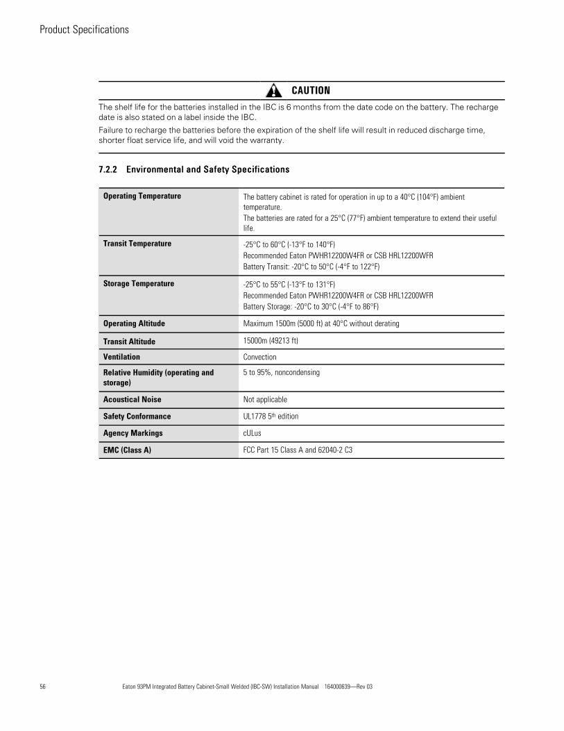
56 Eaton 93PM Integrated Battery Cabinet-Small Welded (IBC-SW) Installation Manual 164000639—Rev 03
CAUTIONThe shelf life for the batteries installed in the IBC is 6 months from the date code on the battery. The rechargedate is also stated on a label inside the IBC.
Failure to recharge the batteries before the expiration of the shelf life will result in reduced discharge time,shorter float service life, and will void the warranty.
77..22..22 EEnnvviirroonnmmeennttaall aanndd SSaaffeettyy SSppeecciiffiiccaattiioonnss
Operating Temperature The battery cabinet is rated for operation in up to a 40°C (104°F) ambienttemperature.The batteries are rated for a 25°C (77°F) ambient temperature to extend their usefullife.
Transit Temperature -25°C to 60°C (-13°F to 140°F)Recommended Eaton PWHR12200W4FR or CSB HRL12200WFRBattery Transit: -20°C to 50°C (-4°F to 122°F)
Storage Temperature -25°C to 55°C (-13°F to 131°F)Recommended Eaton PWHR12200W4FR or CSB HRL12200WFRBattery Storage: -20°C to 30°C (-4°F to 86°F)
Operating Altitude Maximum 1500m (5000 ft) at 40°C without derating
Transit Altitude 15000m (49213 ft)
Ventilation Convection
Relative Humidity (operating andstorage)
5 to 95%, noncondensing
Acoustical Noise Not applicable
Safety Conformance UL1778 5th edition
Agency Markings cULus
EMC (Class A) FCC Part 15 Class A and 62040-2 C3
Product Specifications

Eaton 93PM Integrated Battery Cabinet-Small Welded (IBC-SW) Installation Manual 164000639—Rev 03 57
CChhaapptteerr 88 WWaarrrraannttyy
88..11 LLiimmiitteedd FFaaccttoorryy WWaarrrraannttyy ffoorr TThhrreeee--PPhhaassee EEaattoonn 9933PPMM UUPPSS aanndd 9933PPMM UUPPSS AAcccceessssoorryy PPrroodduuccttssWARRANTOR: The warrantor for the limited warranties set forth herein is Eaton (”Eaton”).
LIMITED WARRANTY: This limited warranty (this ”Warranty”) applies only to the original end-user (the ”End-User”) of the Eaton Three-Phase 93PM UPS and 93PM UPS Accessory Products (the ”Product”) and cannot betransferred. This restriction applies even in the event that the Product is initially sold by Eaton for resale to anEndUser. This Warranty gives you specific legal rights, and you may also have other rights which vary fromState to State (or jurisdiction to jurisdiction).
WHAT THIS LIMITED WARRANTY COVERS: The warrantor warrants, with the terms of this Warranty, thatthe Eaton three-phase UPS electronics, Eaton-built accessories, and Eaton-built battery cabinets (individuallyand collectively, the ”Warranted Items”) are free from defects in material and workmanship.
For Product installed (and currently located) in the fifty (50) United States and the District of Columbia, if, in theopinion of Eaton, a Warranted Item is defective, Eaton's sole obligation, at the option of Eaton, will be torefurbish or replace such defective Warranted Item (including the costs of providing diagnosis, service, andlabor [“labor coverage”]). The defective Warranted Item will be refurbished or replaced onsite at the End-User'slocation or such other location as determined by Eaton. Any parts that are replaced may be new orreconditioned. All parts replaced by Eaton shall become the property of Eaton.
For Product installed (and currently located) outside the fifty (50) United States and the District of Columbia, if,in the opinion of Eaton, a Warranted Item is defective, Eaton's sole obligation, at the option of Eaton, will be torefurbish or replace such defective Warranted Item (not including the costs of labor coverage). The defectiveWarranted Item will be refurbished or replaced onsite at the End-User's location or such other location asdetermined by Eaton. Any parts that are replaced may be new or reconditioned. All parts replaced by Eatonshall become the property of Eaton.
LIMITED WARRANTY PERIOD: The period covered by this Warranty for Product installed (and currentlylocated) in the fifty (50) United States and the District of Columbia is six (6) months from the date of Productpurchase for labor coverage when no startup is performed by an authorized Eaton Customer Service Engineeror Agent or twelve (12) months from the date of Product purchase with startup performed by an authorizedEaton Customer Service Engineer or Agent and twelve (12) months from the date of Product purchase oreighteen (18) months from date of Product shipment, whichever occurs first, for the refurbishment/replacement of parts.
The period covered by this Warranty for Product installed (and currently located) outside the fifty (50) UnitedStates and the District of Columbia is twelve (12) months from the date of Product purchase or eighteen (18)months from the date of Product shipment, whichever occurs first, for the refurbishment/replacement of parts.
WHAT THIS LIMITED WARRANTY DOES NOT COVER: This Warranty does not cover any defects ordamages caused by: (a) failure to properly store the Product before installation, including the ”trickle charge” ofbatteries no later than the date indicated on the packaging; (b) shipping and delivery of the Product if shipping isFOB Factory; (c) neglect, accident, fire, flood, lightning, vandalism, acts of God, Customer's neglect, abuse,misuse, misapplication, incorrect installation; (d) repair or alteration not authorized in writing by Eaton personnelor performed by an authorized Eaton Customer Service Engineer or Agent; or (e) improper testing, operation,maintenance, adjustment, or any modification of any kind not authorized in writing by Eaton personnel orperformed by an authorized Eaton Customer Service Engineer or Agent.
This Warranty is not valid: if the Product's serial numbers have been removed or are illegible. Any WarrantedItems repaired or replaced pursuant to this Warranty will be warranted for the remaining portion of the originalWarranty subject to all the terms thereof. Eaton does not provide a labor warranty for Product located outsideof the fifty (50) United States or the District of Columbia. Any equipment, parts, or materials included in theProduct and not manufactured by Eaton are warranted solely by the manufacturer of such equipment,parts, or materials and are not included as part of this Warranty. Batteries are not warranted by Eaton.

58 Eaton 93PM Integrated Battery Cabinet-Small Welded (IBC-SW) Installation Manual 164000639—Rev 03
THIS WARRANTY IS THE ENDUSER'S SOLE REMEDY AND IS EXPRESSLY IN LIEU OF, AND THERE ARENO OTHER, EXPRESSED OR IMPLIED GUARANTEES ORWARRANTIES (INCLUDING ANY IMPLIEDWARRANTY OF MERCHANTABILITY OR FITNESS FOR ANY PURPOSE, WHICH ARE EXPRESSLYDISCLAIMED). SOME STATES OR JURISDICTIONS DO NOT ALLOW THE EXCLUSION OF EXPRESS ORIMPLIED WARRANTIES, SO THE ABOVE EXCLUSION MAY NOT APPLY TO YOU. IN THAT EVENT, SUCHWARRANTIES ARE LIMITED IN DURATION TO THE LIMITED WARRANTY PERIOD. SOME STATES ORJURISDICTIONS DO NOT ALLOW LIMITATIONS ON HOW LONG AN IMPLIED WARRANTY LASTS ORTHE EXCLUSION OR LIMITATION OF INCIDENTAL OR CONSEQUENTIAL DAMAGES, SO THE ABOVELIMITATIONS AND/OR EXCLUSIONS MAY NOT APPLY TO YOU.
LIMITATION OF LIABILITY: In no event shall Eaton be liable for any indirect, incidental, special orconsequential damages of any kind or type whatsoever, resulting from or in connection with any claim or causeof action, whether brought in contract or in tort (including negligence and strict liability). Some States orjurisdictions do not allow the exclusion of limitation of incidental or consequential damages, so the abovelimitation or exclusion may not apply to you. Eaton shall not be responsible for failure to provide service or partsdue to causes beyond Eaton's reasonable control. In no case will Eaton's liability under this Warranty exceedthe replacement value of the Warranted Items.
END-USER'S OBLIGATIONS: In order to receive the benefits of this Warranty, the End-User must register theproduct warranty (via mail or online at www.eaton.com/pq/register “product registration”); use the Product in anormal way; follow the Product's user's guide; and protect against further damage to the Product if there is acovered defect.
OTHER LIMITATIONS: Eaton's obligations under this Warranty are expressly conditioned upon receiptby Eaton of all payments due to it (including interest charges, if any). During such time as Eaton has notreceived payment of any amount due to it for the Product, in accordance with the contract terms underwhich the Product is sold, Eaton shall have no obligation under this Warranty. Also during such time,the period of this Warranty shall continue to run and the expiration of this Warranty shall not beextended upon payment of any overdue or unpaid amounts.
COSTS NOT RELATED TOWARRANTY: The End-User shall be invoiced for, and shall pay for, all services notexpressly provided for by the terms of this Warranty, including without limitation site calls involving aninspection that determines no corrective maintenance is required. Any costs for replacement equipment,installation, materials, freight charges, travel expenses, or labor of Eaton representatives outside the terms ofthis Warranty will be borne by the End-User.
OBTAININGWARRANTY SERVICE: In the USA, call the Eaton Customer Reliability Center 7x24 at 800-843-9433. Outside of the USA, call your local Eaton sales or service representative, or call the Eaton CustomerReliability Center in the United States at 919845-3633. For comments or questions about this Limited FactoryWarranty, write to the Customer Quality Representative, 8609 Six Forks Road, Raleigh, North Carolina 27615USA.
Warranty

Eaton 93PM Integrated Battery Cabinet-Small Welded (IBC-SW) Installation Manual 164000639—Rev 03 59
Warranty

16400063903164000639 03