ibm z systems qualified dwdm: cisco · overview this ibm® redpaper™ publication is one in a...
TRANSCRIPT

Redpaper
Front cover
IBM z Systems Qualified DWDM Cisco ONS 15454 Multi-Service Transport Platform Release Level 9.6.1.1and WSE Card Release Level 9.8.1.3
Bill White
Pasquale "PJ" Catalano
Andrew Crimmins

IBM REDBOOKS PROMOTIONS
Find and read thousands of IBM Redbooks publications
Search, bookmark, save and organize favorites
Get personalized notifications of new content
Link to the latest Redbooks blogs and videos
DownloadNow
Get the latest version of the Redbooks Mobile App
iOS
Android
Place a Sponsorship Promotion in an IBM Redbooks publication, featuring your business or solution with a link to your web site.
Qualified IBM Business Partners may place a full page promotion in the most popular Redbooks publications. Imagine the power of being seen by users who download millions of Redbooks publications each year!
®
®
Promote your business in an IBM Redbooks publication
ibm.com/RedbooksAbout Redbooks Business Partner Programs
IBM Redbooks promotions

THIS PAGE INTENTIONALLY LEFT BLANK

Overview
This IBM® Redpaper™ publication is one in a series that describes IBM z Systems™ qualified dense wavelength division multiplexing (DWDM) vendor products for IBM Geographically Dispersed Parallel Sysplex™ (IBM GDPS®) solutions with Server Time Protocol (STP). The protocols that are described in this paper are used for IBM supported solutions that require cross-site connectivity of a multisite Parallel Sysplex or remote copy technologies, which can include GDPS and non-GDPS applications. GDPS qualification testing is conducted at the IBM Vendor Solutions Connectivity (VSC) Lab in Poughkeepsie, New York.
IBM and Cisco Systems Inc. have successfully completed qualification testing of the ONS 15454 Multi-Service Transport Platform. This paper describes the applicable environments, protocols, and topologies that are qualified and supported by z Systems for connecting through the ONS 15454 Multi-Service Transport Platform hardware and software, Release 9.6.0.5 and WSE card Release level 9.8.1.31.
This paper is intended for anyone who wants to learn more about the ONS 15454 Multi-Service Transport Platform Release 9.6.0.5 and WSE card Release level 9.8.1.3. This document is not meant to determine qualified products. To ensure that the planned products to be implemented are qualified, registered users can see the IBM Resource Link® library for current information about qualified DWDM vendor products:
https://www.ibm.com/servers/resourcelink/lib03020.nsf/pages/systemzQualifiedWdmProductsForGdpsSolutions?OpenDocument&pathID=
For more information about z Systems qualified DWDM vendor products, see this website:
http://www.redbooks.ibm.com/cgi-bin/searchsite.cgi?query=qualified+AND+wdm&SearchOrder=1&SearchFuzzy=
z Systems GDPS qualification overview
GDPS is an enterprise-wide continuous availability (CA) and disaster recovery (DR) automation solution that can manage recovery from planned and unplanned outages across distributed servers and z Systems platforms. GDPS can be configured in either a single site or in a multisite configuration. It is designed to manage remote copy configuration between storage subsystems, automate Parallel Sysplex operational tasks, and affect failure recovery. This configuration is done from a single point-of-control, which leads to improved application
1 When ONS 15454 Multi-Service Transport Platform system software is downloaded from Cisco.com, check the package name to ensure that the code release level is 9.6.1.1 or 9.8.1.3.
© Copyright IBM Corp. 2016. All rights reserved. ibm.com/redbooks 1

availability. Historically, this solution was known as a GDPS. Today, GDPS continues to be applied as a general term for a suite of business continuity solutions. This term includes solutions that do not require a dispersed or multisite sysplex environment.
GDPS supports the following forms of remote copy in multisite solutions:
� IBM System Storage® Metro Mirror, a synchronous form of remote copy previously known as Peer-to-Peer Remote Copy (PPRC)
� IBM System Storage Global Mirror, an asynchronous form of remote copy for z Systems and distributed systems
� IBM System Storage z/OS® Global Mirror, an asynchronous form of remote copy for z Systems, previously known as Extended Remote Copy (XRC)
Depending on the form of the remote copy that is implemented, the GDPS solution is known as one of these configurations:
� GDPS with Metro Mirror� GDPS with Global Mirror� GDPS with z/OS Global Mirror
GDPS also offers two solutions that combine the technologies of Metro Mirror with either Global Mirror or z/OS Global Mirror. This combination allows clients to meet requirements for CA with zero data loss locally within metropolitan distances (for most failures). The combination also provides a disaster recovery solution in the case of a region-wide disaster.
The disaster recovery solutions include the following options:
� GDPS with Metro and Global Mirror (GDPS with MGM), which is a cascading data replication solution for both z Systems and distributed systems data
� GDPS with Metro and z/OS Global Mirror (GDPS with MzGM), which is a multitarget data replication solution for z Systems data
The GDPS solution is also independent of the disk vendor, if the vendor meets the specific levels of Metro Mirror, Global Mirror, and z/OS Global Mirror architectures.
For more information about GDPS, see this website:
http://www.ibm.com/systems/z/advantages/gdps/index.html
IBM supports DWDM products that are qualified by z Systems for use in GDPS solutions. To obtain this qualification, DWDM vendors obtain licensed IBM patents, intellectual property, and know-how that are related to the GDPS architecture. This licensing provides vendors access to the proprietary IBM protocols and applications that are used in a GDPS environment. These proprietary items include InterSystem Channel (ISC), STP, Metro Mirror, Global Mirror, and z/OS Global Mirror.
Licensing of IBM patents also provides the DWDM vendor with technical information that pertains to future IBM releases. Qualified vendors typically license this information for an extended period. This license allows them to subscribe to the latest GDPS architecture changes and to be among the first to the market with offerings that support these features.
In addition, IBM tests and qualifies these vendor products with the same test environment and procedures that were used to test the protocols that provide the required connectivity of a GDPS configuration. This testing includes functionality and recovery verification. Having
Licensing: Check with your DWDM vendor for current IBM technology and patent licensing status.
2 IBM z Systems Qualified DWDM: Cisco

access to these test facilities allows IBM to configure a fully functional sysplex. By using test facilities, failure and recovery actions can be simulated that cannot be tested as part of a working client environment.
IBM has the facilities to test and qualify these products with both current and previous generation equipment within the VSC Lab. With this qualification testing, IBM can reproduce any conditions that might arise when using this equipment in a client application.
Figure 1 shows the test environment that is used for DWDM vendor qualification and the logical connections for IBM System Storage Metro Mirror and Global Mirror.
Figure 1 VSC Lab environment
Qualification testing
The VSC Lab contains z Systems hardware with software applications that test the interoperability of DWDM products within a GDPS. A typical qualification test cycle is six to eight weeks in length.
The hardware that was used for testing purposes includes (but is not limited to) the following components:
� IBM z Systems™ platforms enabled for STP� IBM System Storage� IBM z Systems qualified Fibre Connection (FICON®) Directors� IBM Ethernet products� IBM zEnterprise® BladeCenter Extension (10 Gigabit Ethernet)
DWDM links of varying distances are deployed by using spools of single-mode fiber in lengths of 5 - 50 km (3.11 - 31.07 miles). Multiple spools are interconnected to test DWDM link protocols up to the maximum supported distances. To achieve the maximum distances that are qualified for GDPS protocols, vendors can use optical amplifiers (OAs) and dispersion compensation units (DCUs). They can insert the OAs and DCUs, at various link points, to condition the signals on the fiber links. These links are connected to the DWDM equipment.
z Systems
IEDN(10 GbE)
OSA-Express (1/10 GbE)
PSIFB LR (STP Messaging)
QualifiedFCP/FICONDirector
FCP/FICON
System Storage System Storage System Storage
FC
P /
FIC
ON
(1/
2/4
/8 G
bp
s)
Up to100Km*
Up to100Km*
IBM System Storage Metro MirrorIBM System Storage Global MirrorFCP/FICON
OSA-Express ( IEDN 10 GbE)
EthernetSwitch
Inter-Switch Link (ISL)
QualifiedFCP/FICONDirector
ISC-3 Peer (STP Messaging)
FCP / FICON (1/2/4/8 Gbps)
z Systems z SystemszBX
*RPQ required for longer distances
3

The operating system and application software are installed to create and stress test the GDPS environment. The software used in the test environment includes, but is not limited to, the following components:
� z/OS, Linux on z Systems, and Parallel Sysplex software exploiters� Coupling Facility Control Code (CFCC)� IBM proprietary software and microcode utility test suites
As part of the GDPS qualification test, IBM proprietary software and microcode utility test suites are used. The software and test suites drive the various GDPS components and protocols to the full data rate of each link type that is transported by the DWDM equipment. This level of testing ensures that the maximum channel utilization is achieved and tested to levels well beyond typical client environments.
The test suites are used for verification of z Systems architecture functionality. For a trial to be classified as successful during these functionality tests, no errors can be detected by the attached subsystems. Any errors that are detected during this testing are captured and analyzed by the test suites.
The test suites are also used for verification of z Systems architecture recovery by creating various fault and error conditions. The recovery tests check for the correct detection of a fault or error condition by the attached subsystems, and ensure that the recovery adheres to z Systems architecture rules.
Some of the recovery tests conducted for each link type include the following actions:
� Link state change interrupt detection and recovery: Links are deliberately broken and reestablished to ensure that detection and error recovery occur correctly.
� Link error threshold and link synchronization error detection and recovery: Errors are deliberately injected, at the application and channel subsystem levels, into the link protocol data streams to ensure that detection and error recovery take place correctly.
� Link service and maintenance package recovery: Link hardware maintenance actions are conducted to ensure that link state change detection and recovery take place correctly.
� Link protection schemes and recovery: Vendor-specific protection methods are tested to ensure that the expected link errors are detected and that recovery takes place correctly.
� STP timing link recovery: STP timing links are broken to ensure that changes to the Coordinated Timing Network (CTN) behave correctly when the break occurs and when the links are reconnected.
GDPS components and protocols
The IBM technologies that are featured in this section are functional components of GDPS and are tested during the qualification process. Clients can also use these components in environments that do not require a full GDPS solution. The testing provides a level of assurance that the components function when used with a qualified DWDM platform.
Qualified DCUs: Fiber-based DCUs are not qualified for use in STP applications unless otherwise stated in the qualification letter.
4 IBM z Systems Qualified DWDM: Cisco

Components
The following GDPS components are tested during the qualification process:
� IBM z Systems platforms� IBM Parallel Sysplex � IBM System Storage� IBM System Storage Metro Mirror (PPRC)� IBM System Storage Global Mirror� IBM System Storage z/OS Global Mirror (XRC)� Vendor DWDM platform� IBM Ethernet products� IBM zEnterprise BladeCenter Extension� Inter-Switch links (ISLs) between two z Systems qualified FICON/Fibre Channel directors
Protocols
Table 1 lists the GDPS connectivity protocols and their data transfer rates. Not all protocols were tested on the ONS 15454 Multi-Service Transport Platform. For a complete list of the protocols and interface cards that were qualified, see Table 2 on page 15.
Table 1 GDPS supported protocols
Often, these supported protocols are also used in environments that are not GDPS. Robust testing is conducted during the qualification process. The results must provide clients with a high level of confidence when using these z Systems qualified DWDM vendor platforms in environments that are not GDPS.
Protocol Data transfer rate
Enterprise Systems Connection (ESCON)a
a. ESCON is not supported on the IBM z13™, zEC12, or zBC12.
200 Mbpsb
b. Effective channel data rate of an ESCON channel is affected by distance.
Fibre Connection (FICON) 1 Gbps
Fibre Connection (FICON) Express2 1, 2 Gbps
Fibre Connection (FICON) Express4 1, 2, 4 Gbps
Fibre Connection (FICON) Express8 2, 4, 8 Gbps
Fibre Channel FC100/ FC200/ FC400/ FC800 1, 2, 4, 8 Gbps
Inter-Switch Link (ISL) FC100/ FC200/ FC400/ FC800/ FC1000/ FC1600
1, 2, 4, 8, 10, 16 Gbps
InterSystem Channel-3 (ISC-3) Peer Modec
c. The zEC12 and zBC12 are the last platforms to support InterSystem Channel-3 (ISC-3).
2 Gbps
STP (ISC-3 Peer Mode with STP message passing)c 2 Gbps
STP (Parallel Sysplex InfiniBand Long Reach (PSIFB LR) 1x IB-single data rate (SDR) with STP message passing)
2.5 Gbps
STP (PSIFB LR 1x IB-double data rate (DDR) with STP message passing)
5 Gbps
Gigabit Ethernet (GbE) 1, 10 Gbps
5

Server Time ProtocolSTP is designed to provide the capability for multiple servers and coupling facilities (CFs) to maintain time synchronization with each other.
STP is a message-based protocol in which STP timekeeping information is passed over externally defined coupling links: ISC-3 Peer Mode and PSIFB links. ISC-3 links in peer mode and PSIFB Long Reach (LR) are the only coupling links that can be used to transport STP messages between data centers over a DWDM platform.
The STP design introduced a concept called CTN, which is a collection of servers and CFs that are synchronized to a time value. This value is called Coordinated Server Time (CST). The CST represents the time for the entire network of servers. A CTN can be configured as either an STP-only CTN or a Mixed CTN. For more information, see the Server Time Protocol Planning Guide, SG24-7280; Server Time Protocol Implementation Guide, SG24-7281; and Server Time Protocol Recovery Guide, SG24-7380.
Figure 2 shows a multisite STP-only CTN.
Figure 2 Multisite STP-only CTN
IBM zEnterprise BladeCenter ExtensionThe IBM zEnterprise BladeCenter Extension (zBX) is available as an option with the IBM z Systems platform. The zBX brings the computing capacity of systems in blade form-factor to the z Systems platform and provides several distributed environments, such as IBM AIX® on POWER7®, Linux on System x, and Microsoft Windows on System x.
The zBX is designed with a redundant hardware infrastructure that supports the multi-platform environment in a seamless, integrated way. Its hardware features are part of the mainframe, not add-ons.
The zBX and the z Systems platform are interconnected through a high-speed private network that is called an intraensemble data network (IEDN). The IEDN consists of
PSIFB LR
or
ISC-3 Peer
with STP Messaging
ISL
System Storage System Storage
z Systems z Systems
Site 1 Site 2
QualifiedFICON
Director
FCP/FICON
FCP/FICON
QualifiedFICON
Director
FCP/FICON
FCP/FICON
EthernetSwitch
OSA-Express
(1 GbE and 10 GbE)
6 IBM z Systems Qualified DWDM: Cisco

top-of-rack 10 GbE switches in the zBX and OSA-Express 10 GbE features in the z Systems platform.
The IEDN provides private and secure data paths between all elements of a z Systems ensemble. A z Systems ensemble is a collection of highly virtualized diverse systems that can be managed as a single logical entity, and where diverse workloads can be deployed. It is composed of up to eight nodes, each of which consists of a z Systems platform and an optional zBX (Figure 3).
Figure 3 z Systems node
GDPS/PPRC and GDPS with Global Mirror support zBX hardware components, providing workload failover for automated multi-site recovery. These capabilities can help facilitate the management of planned and unplanned outages across the z Systems platform.
For more information about the zBX, see Building an Ensemble Using IBM zEnterprise Unified Resource Manager, SG24-7921.
IBM 10 Gigabit Ethernet (10GbE) RoCE Express The 10GbE RoCE Express feature uses Remote Direct Memory Access over Converged Ethernet (RoCE) and is designed to provide fast memory-to-memory communications between two z Systems platforms.
Use of the 10GbE RoCE Express feature helps reduce consumption of CPU resources for applications that use the TCP/IP stack. It might also help to reduce network latency with memory-to-memory transfers using Shared Memory Communications over Remote Direct Memory Access (SMC-R).
SMC-R uses a TCP connection to determine eligibility to use the RoCE fabric and then to build a point-to-point SMC-R link for the data flow over the RDMA connection path. TCP/IP is used not only to establish the TCP/IP and RDMA connections, but also for Keepalive functions and to terminate the TCP and the associated RDMA connections. The standard TCP/IP path over an OSA-Express port need not be dedicated to RDMA usage. It can be used simultaneously for other, non-RDMA traffic.
zBX
z Systems Top-of-rackSwitches
OSA-Express10 GbE Intraensemble
Data Network
7

The OSA-Express port and the 10GbE RoCE Express port can be attached to a 10 Gigabit Ethernet switch or they can both have a point-to-point connection (see Figure 4).
Figure 4 RoCE in a two site configuration using DWDM
The 10GbE RoCE Express feature uses a short reach (SR) laser as the optical transceiver and supports the use of a multimode fiber optic cable terminated with an LC Duplex connector.
If the IBM 10GbE RoCE Express features are connected to 10 GbE switches, the switches must support the following requirements:
� Global Pause function enabled� Priority flow control (PFC) disabled� No firewalls or routing
For more information about the 10Gbe RoCE Express feature, see IBM z Systems Connectivity Handbook, SG24-5444.
Connectivity considerations with DWDM
When planning DWDM intersite connectivity for GDPS environments, consider the following items:
� Differential delay: The difference in the distance or latency between a transmit fiber and a receive fiber in a single fiber pair of a timing link. To ensure correct server time synchronization, examine the end-to-end lengths of the transmit and receive fibers within an individual STP link (ISC-3 Peer Mode with STP messaging or PSIFB). The lengths must not exceed the equivalent of 900 meters differential delay between the transmit and receive paths of the link. This stipulation includes all DWDM components, OAs, DCUs2, dark fiber links, and any time-division multiplexing (TDM)-based aggregation.
� If both the CF data and STP timing information must be transmitted between two servers, you cannot select a subset of coupling links to be used just for STP timing information.
z Systems
OSA-Express10 GbE
10GbE RoCE Express
OSA-Express10 GbE
10GbE RoCE Express
10 Gigabit Ethernet
z Systems
Note: The 10GbE RoCE Express feature is only supported on the z13, zEC12, and zBC12.
2 Fiber-based DCUs are not qualified for use in STP applications unless otherwise stated in the qualification letter.
Supported devices: DCUs might contain significant lengths of fiber that must be included in the differential delay calculation for timing links. Not all DCUs are supported. Check the qualification letters for supported devices.
8 IBM z Systems Qualified DWDM: Cisco

� Protection schemes, for individual timing links or for fiber trunks that transport timing links, must be bidirectional (switch both transmit and receive paths during a failure). This configuration ensures that the correct differential delay is maintained.
� DWDM configurations must have high availability topologies in place to avoid single points of failure.
� Fiber trunk protection schemes must be designed with two trunk switching modules and four site-to-site fiber pairs that are carried over at least two diverse routes. STP links must connect by using separate trunk switching modules to ensure that a fiber trunk protection event does not interrupt all timing links simultaneously.
� TDM-based aggregation DWDM hardware can be used for STP links (ISC-3 Peer Mode or PSIFB LR with STP message passing) only if it is qualified for STP usage.
� GDPS DWDM configuration must be a point-to-point fixed dark fiber network.
For more information about the STP recovery process, see the Server Time Protocol Recovery Guide, SG24-7380.
Technical description
The ONS 15454 Multi-Service Transport Platform is a scalable, high-speed fiber-optic data transport system. It consists of a modular chassis, which can be interconnected to form an optical network that supports International Telecommunications Union (ITU)-specific wavelengths. The wavelengths are multiplexed onto a single pair of fibers by using DWDM.
The optical network that connects the ONS 15454 Multi-Service Transport Platform can be configured in a two-site point-to-point, multisite ring, or meshed network.
The ONS 15454 Multi-Service Transport Platform was qualified by using Software Release 9.6.0.5 and WSE card Release level 9.8.1.3. It has a modular chassis that can house multiple optical interface cards, depending on the chassis. Multiple ONS 15454 Multi-Service Transport Platform chassis can be interconnected to support larger quantities of client interfaces.
Interface cards and modules
This section includes a detailed list of the ONS 15454 Multi-Service Transport Platform optical interface cards and modules that are qualified by z Systems GDPS testing.
The following optical interface cards and modules are qualified by z Systems GDPS testing:
� Transponder cards
Transponder cards connect client equipment to the DWDM platform. The transponder card converts client optical signals to an ITU-compliant DWDM wavelength for transmission to the remote site.
ONS 15454 Multi-Service Transport Platform Transponder cards have pluggable client optical transceivers.
Note: IBM only qualifies point-to-point topologies for GDPS solutions. Other topologies might contain significant length variations of fiber that go beyond the differential delay limits for timing links and are therefore not supported.
9

The following ONS 15454 Multi-Service Transport Platform Transponder card types are qualified:
– 15454-10Ex-L1-xx.x=: Extended Performance 10G Multirate Transponder, Full C-Band ITU tunable
– 15454-10E-L1-xx.x=: Extended Performance 10G Multirate Transponder, Full C-Band ITU tunable
– 15454-OTU2-XP=: Four port XFP 10G Transponder, with pluggable network transceivers, Full C-Band ITU Tunable or one fixed channel ITU
– 15454-M-10X10G-LC (in Transponder Mode): 10 Port 10G Client Card in 5:5 Transponder mode
– 15454-WSE-L-K9=: 10 Port 10G Client 5:5 Transponder Card with Encryption
– 15454-AR-MXP= (in Transponder mode): Multi-rate Transponder/Muxponder with 8 SFP and 2 XFP ports for client/trunk connections. Supports four client ports in Transponder Mode
– 15454-AR-XPE= (in Transponder mode): Multi-rate Transponder/Muxponder with 8 SFP and 2 XFP ports for client/trunk connections. Supports four client ports In Transponder Mode
� Muxponder cards
The ONS 15454 Multi-Service Transport Platform support the aggregation of client signals. Muxponder cards use TDM to aggregate multiple client optical interfaces for transport over a single ITU-specific wavelength.
Muxponder cards have pluggable client optical transceivers that support different client protocols and fiber types.
The following Muxponder card types are qualified for use in the ONS 15454 Multi-Service Transport Platform:
– 15454-10DME-C=: 10G Data Muxponder 80-Channel Tunable
– 15454-10DMEX-C=: Extended Performance 10G Data Muxponder 80-Channel Tunable
– 15454-40E-MXP-C=: Four port 40 Gbps Data Muxponder Full C-Band ITU Tunable
– 15454-40ME-MXP-C=: Four port 40 Gbps Data Muxponder Full C-Band ITU Tunable
– 15454-M-10X10G-LC (Client Card) and 15454-M-100G-LC-C (Trunk Card): 100G Trunk Card/10 Port 10G Line Card Combination
– 15454-M-10X10G-LC (Client Card) and 15454-M-100ME-LC-C (Trunk Card): 100G Trunk Card/10 Port 10G Line Card Combination
– 15454-AR-MXP= (in Muxponder mode): 10G Multi-rate Transponder/Muxponder with 8 SFP and 2 XFP ports for client/trunk connections. Supports up to eight client ports in Muxponder Mode
– 15454-AR-XPE= (in Muxponder mode): 20G Multi-rate Transponder/Muxponder with 8 SFP and 2 XFP ports for client/trunk connections. Supports up to eight client ports in Muxponder Mode
� Optical filter modules
Optical filter modules are optical components that combine (multiplex) or separate (demultiplex) multiple optical signals onto a fiber link.
The reconfigurable optical add-drop multiplexer (ROADM) allows adding or dropping of optical signals at the wavelengths layer without an optical-electrical-optical conversion in multiple directions in an optical cross-connect system.
10 IBM z Systems Qualified DWDM: Cisco
The ONS 15454 Multi-Service Transport Platform supports a series of optical filter modules that can multiplex or demultiplex signals onto a fiber pair or a single fiber for transmission between sites. Optical filter modules are used in a tiered arrangement to multiplex or demultiplex groups of client channels on a fiber link for transmission between sites.
� Optical amplifier (OA)
The OA module provides inline optical amplification of multiple ITU-specific wavelengths within a fiber. For particular extended distances, the use of these OAs might be required.
� Dispersion compensation unit (DCU)
The DCU provides compensation to chromatic dispersion fiber impairment, which causes signal degradation and limits the transmission distance.
The following ONS 15454 Multi-Service Transport Platform DCU types3 are qualified (all are Low Latency DCUs based on Fiber Bragg Grating Technology):
– 15216-FBGDCU-165
– 15216-FBGDCU-331
– 15216-FBGDCU-496
– 15216-FBGDCU-661
– 15216-FBGDCU-826
– 15216-FBGDCU-992
– 15216-FBGDCU-1157
– 15216-FBGDCU-1322
– 15216-FBGDCU-1653
– 15216-FBGDCU-1983
� Protection Switch Module (PSM)
The ONS 15454 Multi-Service Transport Platform supports optically switched fiber protection for point-to-point DWDM links with the use of the PSM. The PSM protects site-to-site traffic from physical damage to a fiber or fiber pair by switching bidirectionally to a redundant fiber or fiber pair.
The following Cisco Systems Inc. ONS 15454 Multi-Service Transport Platform PSM types are qualified:
– The 15454-PSM=: Optical Protection Switching Module (in Bi-Directional Mode) is a qualified PSM type of the ONS 15454 Multi-Service Transport Platform (supported for use with STP links).
� Y-Cable line card protection4
The ONS 15454 Multi-Service Transport Platform supports per wavelength protection from Transponder module failure and site-to-site fiber failure with the Y-Cable protection. The Y-Cable splits a client signal into two Transponder modules that are configured to send their trunk facing line signals over two diverse site-to-site links.
3 This DCU is qualified for STP.
Delay calculation for timing links: Some DCUs contain significant lengths of fiber, which must be included in the differential delay calculation for timing links.
4 Y-cable protection is not supported with the 15454-WSE-L-K9= client card, 10 Gbps ISLs with the 15454-M-10X10G-LC client card in Transponder mode, or for the 15454-M-10x10G-LC client card in 10:1 Muxponder mode paired with either a 15454-M-100G-LC-C or 15454-M-100ME-LC-C trunk card.
11

The 15454-YCBL-LC= is a qualified Y-Cable protection drawer type of the ONS 15454 Multi-Service Transport Platform.
Topologies and protection schemes
z Systems qualifies a two-site point-to-point DWDM network topology and protection against failures in site-to-site fiber links or failures in individual components within the DWDM network for GDPS.
GDPS is a high-availability solution that can use several protection schemes. Some restrictions apply for particular protocols, such as STP (ISC-3 Peer Mode and PSIFB LR) links.
Protection schemesThe ONS 15454 Multi-Service Transport Platform provides the following protection schemes:
� Unprotected
An unprotected transponder or Muxponder card is connected to one client interface and to one site-to-site fiber link only. A failure of the transponder or Muxponder card or the site-to-site fiber link results in a loss of client communications.
� Client-based protection
Client-based protection uses at least two client interfaces that are connected to the DWDM. These interfaces are arranged so that the transponder or Muxponder cards that connect the two sites are distributed over two diverse site-to-site fiber links. The client device is responsible for ensuring that a failure of a DWDM module or of a single site-to-site fiber link does not result in a total loss of client communications.
GDPS timing links (STP) are qualified for use in a client-based protection scheme if they are using separate paths (routes).
Note: The Y-cable is not qualified for use with STP links.
Important: Protection schemes must guarantee the correct differential delay for individual timing links:
� STP links must not exceed the equivalent of 900 meters differential delay between the transmit and receive paths of the link.
Diagram components: For simplicity, several of the components in the optical path are not shown in the diagrams in this section.
12 IBM z Systems Qualified DWDM: Cisco
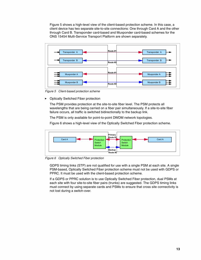
Figure 5 shows a high-level view of the client-based protection scheme. In this case, a client device has two separate site-to-site connections: One through Card A and the other through Card B. Transponder card-based and Muxponder card-based schemes for the ONS 15454 Multi-Service Transport Platform are shown separately.
Figure 5 Client-based protection scheme
� Optically Switched Fiber protection
The PSM provides protection at the site-to-site fiber level. The PSM protects all wavelengths that are being carried on a fiber pair simultaneously. If a site-to-site fiber failure occurs, all traffic is switched bidirectionally to the backup link.
The PSM is only available for point-to-point DWDM network topologies.
Figure 6 shows a high-level view of the Optically Switched Fiber protection scheme.
Figure 6 Optically Switched Fiber protection
GDPS timing links (STP) are not qualified for use with a single PSM at each site. A single PSM-based, Optically Switched Fiber protection scheme must not be used with GDPS or PPRC. It must be used with the client-based protection scheme.
If a GDPS or PPRC solution is to use Optically Switched Fiber protection, dual PSMs at each site with four site-to-site fiber pairs (trunks) are suggested. The GDPS timing links must connect by using separate cards and PSMs to ensure that cross site connectivity is not lost during a switch-over.
Transponder A Transponder A
Transponder B Transponder B
Muxponder A Muxponder A
Aggregation Card B Aggregation Card BMuxponder B Muxponder B
Route #1
Route #2
Route #1
Route #2
ProtectionSwitchModule
ProtectionSwitchModule
PrimaryRoute #1
BackupRoute #2
Card A Card A
13

Figure 7 shows a high-level view of the dual Optically Switched Fiber protection scheme.
Figure 7 Dual Optically Switched Fiber protection
� Y-Cable Line Card Protection
Y-Cable Line Card protection provides per wavelength protection against a Transponder module failure, and also against a site-to-site fiber failure. The signal received from the client is optically split by using a Y-Cable and connected into two Transponder modules. The Transponder modules are configured to send their trunk facing signals over two diverse site-to-site fiber links. At the remote site, WDM control logic ensures that the client facing transmit laser of only one Transponder module is enabled for the remote client interface. Transponder-based Y-Cable Line Card protection is supported on the ONS 15454 Multi-Service Transport Platform.
GDPS timing links (STP) are not qualified for use with Y-Cable.
Figure 8 shows a high-level view of the Y-Cable Line Card protection scheme.
Figure 8 Y-Cable Line card protected scheme
Protection scheme intermixAll protection schemes can be intermixed within the same ONS 15454 Multi-Service Transport Platform chassis or network on an individual client interface basis.
ProtectionSwitchModule
ProtectionSwitchModule
Card A
PrimaryRoute #1
BackupRoute #2
PrimaryRoute #2
ProtectionSwitchModule
ProtectionSwitchModuleCard B
BackupRoute #1
Card B
Card A
Transponder A Transponder A
Transponder B Transponder B
One Transponder laser is enabled to Client
Client input signal is optically split
Route #1
Route #2
14 IBM z Systems Qualified DWDM: Cisco

Interface card specifications
Table 2 lists the specifications of the qualified ONS 15454 Multi-Service Transport Platform interface cards and tested protocols.
For particular extended distances, the use of OAs and DCUs might be required. For distance and link budget specifications, reference the DWDM vendor documentation.
Table 2 Qualified client interface card details
Card type and protocol Fiber type Light source Qualified distancea,b
15454-OTU2-XP=, 4 port 10 Gbps XFP transponder full C-Band Tunable ITUc
ISL (10 Gbps)d,e SM 1310 nm 100 km (62 miles)
ISL (10 Gbps)d,e MM 850 nm 100 km
Gigabit Ethernet (10 Gbps)f SM 1310 nm 100 km
Gigabit Ethernet (10 Gbps)f MM 850 nm 100 km
PSIFB 1x IFB-DDR LR (5 Gbps)g with STP SM 1310 nm 100 km
15454-10Ex-L1-xx.x=, Extended performance 10 Gbps multirate transponder full C-band Tunable ITUc
ISL (10 Gbps)d,e SM 1310 nm 150 km (93 miles)
ISL (10 Gbps)d,e MM 850 nm 150 km
Gigabit Ethernet (10 Gbps)f SM 1310 nm 150 km
Gigabit Ethernet (10 Gbps)f MM 850 nm 150 km
PSIFB 1x IFB-DDR LR (5 Gbps)g with STP SM 1310 nm 150 km
15454-10E-L1-xx.x=, Extended performance 10 Gbps multirate transponder full C-band Tunable ITUc
ISL (10 Gbps)d,e SM 1310 nm 150 km
ISL (10 Gbps)d,e MM 850 nm 150 km
Gigabit Ethernet (10 Gbps)f SM 1310 nm 150 km
Gigabit Ethernet (10 Gbps)f MM 850 nm 150 km
15454-10DME-C=, 10G Data Muxponder 80-Channel Tunablec
Fibre Channel (2, 4 Gbps) SM 1310 nm 150 km
Fibre Channel (2, 4 Gbps) MM 850 nm 150 km
FICON (2, 4 Gbps)d SM 1310 nm 150 km
FICON (2, 4 Gbps)d MM 850 nm 150 km
ISL (2, 4 Gbps)d SM 1310 nm 150 km
ISL (2. 4 Gbps)d MM 850 nm 150 km
15454-10DMEX-C=, Extended Performance 10G Data Muxponder 80-Channel Tunablec
Fibre Channel (2, 4 Gbps) SM 1310 nm 150 km
Fibre Channel (2, 4 Gbps) MM 850 nm 150 km
FICON (2, 4 Gbps)d SM 1310 nm 150 km
FICON (2, 4 Gbps)d MM 850 nm 150 km
ISL (2, 4 Gbps)d SM 1310 nm 150 km
15

ISL (2. 4 Gbps)d MM 850 nm 150 km
15454-40E-MXP-C=, 4 port 40 Gbps data muxponder full C-Band Tunable ITUc
ISL (8, 10 Gbps)d,h SM 1310 nm 150 km
ISL (8, 10 Gbps)d,h MM 850 nm 150 km
Gigabit Ethernet (10 Gbps)f SM 1310 nm 150 km
Gigabit Ethernet (10 Gbps)f MM 850 nm 150 km
15454-40ME-MXP-C=, 4 port 40 Gbps data muxponder full C-Band Tunable ITUc
ISL (8, 10 Gbps)d,h SM 1310 nm 150 km
ISL (8, 10 Gbps)d,h MM 850 nm 150 km
Gigabit Ethernet (10 Gbps)f SM 1310 nm 150 km
Gigabit Ethernet (10 Gbps)f MM 850 nm 150 km
15454-M-10X10G-LC (client card) and 15454-M-100G-LC-C (trunk card), 10 port 100G muxponder client and line card combinationc
ISL (8, 10 Gbps)d,i SM 1310 nm 150 km
ISL (8, 10 Gbps)d,i MM 850 nm 150 km
Gigabit Ethernet (10 Gbps)f SM 1310 nm 150 km
Gigabit Ethernet (10 Gbps)f MM 850 nm 150 km
15454-M-10X10G-LC (client card) and 15454-M-100ME-LC-C (trunk card), 10 port 100G muxponder client and line card combinationc
ISL (8, 10 Gbps)d,i SM 1310 nm 150 km
ISL (8, 10 Gbps)d,i MM 850 nm 150 km
Gigabit Ethernet (10 Gbps)f SM 1310 nm 150 km
Gigabit Ethernet (10 Gbps)f MM 850 nm 150 km
15454-M-10X10G-LC (client card) in 5:5 Transponder Modec
ISL (8, 10 Gbps)d,i SM 1310 nm 150 km
ISL (8, 10 Gbps)d,i MM 850 nm 150 km
Gigabit Ethernet (10 Gbps)f SM 1310 nm 150 km
Gigabit Ethernet (10 Gbps)f,j MM 850 nm 150 km
15454-AR-MXP=, 10G Multirate Transponder/Muxponder with 8 SFP and 2 XFP ports for client/trunk connectionsc
ESCON (200 Mbps) MM 1310 nm 100 km
Fibre Channel (2, 4 Gbps)k,l SM 1310 nm 150 km
Fibre Channel (2, 4 Gbps)k,l MM 850 nm 150 km
FICON (2, 4 Gbps)d,k,l SM 1310 nm 150 km
FICON (2, 4 Gbps)d,k,l MM 850 nm 150 km
ISL (2, 4, 8 Gbps)d,l SM 1310 nm 150 km
ISL (2, 4, 8 Gbps)d,l MM 850 nm 150 km
ISC-3 Peer Mode (2 Gbps)g with STPm SM 1310 nm 150 km
Card type and protocol Fiber type Light source Qualified distancea,b
16 IBM z Systems Qualified DWDM: Cisco

15454-AR-XPE=, 20G Multirate Transponder/Muxponder with 8 SFP and 2 XFP ports for client/trunk connectionsc
ESCON (200 Mbps) MM 1310 nm 100 km
Fibre Channel (2, 4 Gbps)k,l SM 1310 nm 150 km
Fibre Channel (2, 4 Gbps)k,l MM 850 nm 150 km
FICON (2, 4 Gbps)d,k,l SM 1310 nm 150 km
FICON (2, 4 Gbps)d,k,l MM 850 nm 150 km
ISL (2, 4, 8 Gbps)d,l SM 1310 nm 150 km
ISL (2, 4, 8 Gbps)d,l MM 850 nm 150 km
15454-WSE-L-K9=, 10 Port 10G Client 5:5 Transponder Card with Encryptionc,n
ISL (8, 10 Gbps)d,i SM 1310 nm 150 km
ISL (8, 10 Gbps)d,i MM 850 nm 150 km
Gigabit Ethernet (10 Gbps)f SM 1310 nm 150 km
Gigabit Ethernet (10 Gbps)f MM 850 nm 150 km
SM = single-mode fiber (9/125 micron)MM = multimode fiber (50/125 or 62.5/125 micron)
a. Qualified distance is based on the VSC Lab test environment, which is a physical point-to-point topology without any intermediate nodes besides OAs and DCUs.
b. Requires request for price quotation (RPQ) - 8P2340 (z196, z114), 8P2581 (zEC12), 8P2781(zBC12), 8P2981 (z13) for distances over 100 km.
c. Protocol and wavelength support depend on a pluggable client interface transceiver.d. Protocol is configured as Fibre Channel Protocol (FCP) on DWDM.e. 10 Gbps ISLs from Brocade switches/Directors are not supported on the following modules:
15454-10Ex-L1-xx.x=, 15454-10E-L1-xx.x=, 15454-OTU2-XP=.f. The 10 GbE connection is also qualified with the IBM z Systems intraensemble data network
(IEDN).g. Multiple STP links can be supported on the same card.h. The 40E and 40ME Muxponder cards currently do not initialize properly with 8 Gbps ISLs from
Brocade switches running FOS 7.1+. Defect #560946 addresses this interoperability issue. Ensure that the level of FOS that is running contains this modification, and the ISL is configures as an E-Port. The ISL can be initialized manually by toggling the ISL R_RDY mode on the switch, using the command portCfgISLMode on both sides of the cascaded link.
i. To run 10 Gbps ISLs from Brocade switches/Directors over the 10 x 10G card (either in 5:5 Transponder mode or in 10:1 Muxponder mode paired with a 100E or 100ME card) or the WSE card, the “Squelch” feature must be disabled on the card.
j. On this card, the 10 GbE connection is also qualified for RoCE using SMC-R on the z13, zEC12, and zBC12.To get 10GbE RoCE Express for SMC-R links to come online over the Cisco 10 x 10G card in 5:5 Transponder mode, users must take the TCP/IP stack down on both sides of the link (in the z Systems), and take the line side of the Cisco DWDM link down on the 10 x 10G card for the associated client port. They then bring the TCP/IP stack back up so the RoCE link goes into the “Starting” state, and bring the line side of the Cisco DWDM link up on the 10 x 10G card for the associated client port.
k. The 15454-AR-XPE= and 15454-AR-MXP= cards do not support auto-negotiation of the link speeds. For z Systems FICON and FCP client links with these interface cards, cascaded Directors/switches are required to set the link speed at both ends of the link.
l. The 15454-AR-XPE= and 15454-AR-MXP= cards in 4Gbps Transponder mode are not supported for direct attachment to the IBM z systems FICON Express16s card. ISLs between Cascaded Directors/switches are required.
m. ISC-3 without STP is supported.
Card type and protocol Fiber type Light source Qualified distancea,b
17

References
For more information about z Systems connectivity, see these resources:
� z Systems I/O connectivity home page
http://www.ibm.com/systems/z/hardware/connectivity/index.html
� IBM z Systems Connectivity Handbook, SG24-5444
http://www.redbooks.ibm.com/abstracts/sg245444.html
� FICON Planning and Implementation Guide, SG24-6497
http://www.redbooks.ibm.com/abstracts/sg246497.html
� Implementing and Managing InfiniBand Coupling Links on IBM System z, SG24-7539
http://www.redbooks.ibm.com/abstracts/sg247539.html
For more information about GDPS, see these resources:
� GDPS home page
http://www.ibm.com/systems/z/advantages/gdps/index.html
� IBM GDPS Family of Products: An Introduction to Concepts and Capabilities, SG24-6374
http://www.redbooks.ibm.com/abstracts/sg246374.html
For more information about STP, see these resources:
� Parallel Sysplex home page:
http://www.ibm.com/systems/z/advantages/pso/index.html
� Server Time Protocol Planning Guide, SG24-7280
http://www.redbooks.ibm.com/abstracts/sg247280.html
� Server Time Protocol Implementation Guide, SG24-7281
http://www.redbooks.ibm.com/abstracts/sg247281.html
� Server Time Protocol Recovery Guide, SG24-7380
http://www.redbooks.ibm.com/abstracts/sg247380.html
For current information about qualified DWDM vendor products, registered users can see the library at the IBM Resourcelink website:
https://www.ibm.com/servers/resourcelink/lib03020.nsf/pages/systemzQualifiedWdmProductsForGdpsSolutions?OpenDocument&pathID=
For current information about qualified vendor switches and directors for IBM z Systems FICON and FCP channels, registered users can see the library at the Resourcelink website:
https://www.ibm.com/servers/resourcelink/lib03020.nsf/pages/switchesAndDirectorsQualifiedForIbmSystemZRFiconRAndFcpChannels?OpenDocument
n. The 15454-WSE-L-K9= card is only qualified for use in Cisco 15454 Chassis running Software Release 9.8.1.3. The line-side output of the WSE card can be fed into the Muxes, amplifiers, and DCUs in another set of 15454 chassis running a different qualified release, such as 9.6.1.1.
Qualified distances: Consult your storage area network (SAN) switch vendors for qualified ISL-supported distances.
18 IBM z Systems Qualified DWDM: Cisco

For more information about IBM Redbooks® publications on z Systems qualified DWDM vendor products, see this website:
http://www.redbooks.ibm.com/cgi-bin/searchsite.cgi?query=qualified+AND+wdm&SearchOrder=1&SearchFuzzy=
For more information about the ONS 15454 Multi-Service Transport Platform, see this website:
http://www.Cisco.com
Authors
This Redpaper publication was produced by a team of specialists working at the IBM International Technical Support Organization, Poughkeepsie Center.
Bill White is a Project Leader at the IBM International Technical Support Organization, Poughkeepsie, NY.
Pasquale "PJ" Catalano is a z Systems I/O Test Architect on the Engineering System Test & Integration team in Poughkeepsie, NY. He has 12 years of experience in vendor qualification testing. He has a Masters of Science in Electrical Engineering from the State University of New York at New Paltz.
Andrew Crimmins is the Technical Team Leader at the IBM Vendor Solutions Connectivity Lab in Poughkeepsie, NY. He has five years of experience in DWDM vendor qualification testing. He has a Bachelors of Science in Computer Engineering from the State University of New York at New Paltz.
Now you can become a published author, too!
Here’s an opportunity to spotlight your skills, grow your career, and become a published author - all at the same time! Join an ITSO residency project and help write a book in your area of expertise, while honing your experience using leading-edge technologies. Your efforts will help to increase product acceptance and customer satisfaction, as you expand your network of technical contacts and relationships. Residencies run from two to six weeks in length, and you can participate either in person or as a remote resident working from your home base.
Obtain more about the residency program, browse the residency index, and apply online at:
ibm.com/redbooks/residencies.html
Stay connected to IBM Redbooks
� Find us on Facebook:
http://www.facebook.com/IBMRedbooks
� Follow us on Twitter:
http://twitter.com/ibmredbooks
19

� Look for us on LinkedIn:
http://www.linkedin.com/groups?home=&gid=2130806
� Explore new Redbooks publications, residencies, and workshops with the IBM Redbooks weekly newsletter:
https://www.redbooks.ibm.com/Redbooks.nsf/subscribe?OpenForm
� Stay current on recent Redbooks publications with RSS Feeds:
http://www.redbooks.ibm.com/rss.html
20 IBM z Systems Qualified DWDM: Cisco

Notices
This information was developed for products and services offered in the US. This material might be available from IBM in other languages. However, you may be required to own a copy of the product or product version in that language in order to access it.
IBM may not offer the products, services, or features discussed in this document in other countries. Consult your local IBM representative for information on the products and services currently available in your area. Any reference to an IBM product, program, or service is not intended to state or imply that only that IBM product, program, or service may be used. Any functionally equivalent product, program, or service that does not infringe any IBM intellectual property right may be used instead. However, it is the user's responsibility to evaluate and verify the operation of any non-IBM product, program, or service.
IBM may have patents or pending patent applications covering subject matter described in this document. The furnishing of this document does not grant you any license to these patents. You can send license inquiries, in writing, to:IBM Director of Licensing, IBM Corporation, North Castle Drive, MD-NC119, Armonk, NY 10504-1785, US
INTERNATIONAL BUSINESS MACHINES CORPORATION PROVIDES THIS PUBLICATION “AS IS” WITHOUT WARRANTY OF ANY KIND, EITHER EXPRESS OR IMPLIED, INCLUDING, BUT NOT LIMITED TO, THE IMPLIED WARRANTIES OF NON-INFRINGEMENT, MERCHANTABILITY OR FITNESS FOR A PARTICULAR PURPOSE. Some jurisdictions do not allow disclaimer of express or implied warranties in certain transactions, therefore, this statement may not apply to you.
This information could include technical inaccuracies or typographical errors. Changes are periodically made to the information herein; these changes will be incorporated in new editions of the publication. IBM may make improvements and/or changes in the product(s) and/or the program(s) described in this publication at any time without notice.
Any references in this information to non-IBM websites are provided for convenience only and do not in any manner serve as an endorsement of those websites. The materials at those websites are not part of the materials for this IBM product and use of those websites is at your own risk.
IBM may use or distribute any of the information you provide in any way it believes appropriate without incurring any obligation to you.
The performance data and client examples cited are presented for illustrative purposes only. Actual performance results may vary depending on specific configurations and operating conditions.
Information concerning non-IBM products was obtained from the suppliers of those products, their published announcements or other publicly available sources. IBM has not tested those products and cannot confirm the accuracy of performance, compatibility or any other claims related to non-IBM products. Questions on the capabilities of non-IBM products should be addressed to the suppliers of those products.
Statements regarding IBM's future direction or intent are subject to change or withdrawal without notice, and represent goals and objectives only.
This information contains examples of data and reports used in daily business operations. To illustrate them as completely as possible, the examples include the names of individuals, companies, brands, and products. All of these names are fictitious and any similarity to actual people or business enterprises is entirely coincidental.
COPYRIGHT LICENSE:
This information contains sample application programs in source language, which illustrate programming techniques on various operating platforms. You may copy, modify, and distribute these sample programs in any form without payment to IBM, for the purposes of developing, using, marketing or distributing application programs conforming to the application programming interface for the operating platform for which the sample programs are written. These examples have not been thoroughly tested under all conditions. IBM, therefore, cannot guarantee or imply reliability, serviceability, or function of these programs. The sample programs are provided “AS IS”, without warranty of any kind. IBM shall not be liable for any damages arising out of your use of the sample programs.
© Copyright IBM Corp. 2016. All rights reserved. 21

Trademarks
IBM, the IBM logo, and ibm.com are trademarks or registered trademarks of International Business Machines Corporation, registered in many jurisdictions worldwide. Other product and service names might be trademarks of IBM or other companies. A current list of IBM trademarks is available on the web at “Copyright and trademark information” at http://www.ibm.com/legal/copytrade.shtml
The following terms are trademarks or registered trademarks of International Business Machines Corporation, and might also be trademarks or registered trademarks in other countries.
AIX®FICON®GDPS®Geographically Dispersed Parallel
Sysplex™IBM®IBM z™
IBM z Systems™IBM z13™Parallel Sysplex®POWER7®Redbooks®Redpaper™Redbooks (logo) ®
Resource Link®System Storage®z Systems™z/OS®z13™zEnterprise®
The following terms are trademarks of other companies:
Inc., and Inc. device are trademarks or registered trademarks of Kenexa, an IBM Company.
Linux is a trademark of Linus Torvalds in the United States, other countries, or both.
Microsoft, Windows, and the Windows logo are trademarks of Microsoft Corporation in the United States, other countries, or both.
Other company, product, or service names may be trademarks or service marks of others.
22 IBM z Systems Qualified DWDM: Cisco


ibm.com/redbooks
Printed in U.S.A.
Back cover
ISBN 0738455288
REDP-5372-00
®