ibp-202 - ctc u · the ibp-202 optical bypass switch is an industrial grade external bypass switch...
TRANSCRIPT

10101
0101
R
Specifications & design are subject to change without prior notice. Please visit CTC Union website for more details. www.ctcu.com / [email protected] V1.0
7
7-47
▪ 100M/1G/2.5G/10G Ethernet or Telecom applications
▪ SC/ST/LC SM or MM optical
▪ Optical bypass switching time <10ms
▪ Provides rotary switch to set delay boot time (0~180 seconds)
▪ EN50121-4, EN61000-6-2, EN61000-6-4,CE, FCC certified
EN61000-6-2EN61000-6-4EN50121-4
The IBP-202 Optical Bypass Switch is an industrial grade external bypass switch for optical-node failure in fiber optical network infrastructures. The IBP-202 Optical Bypass Switch prevents and saves communication from network failures during power loss. When power failure occurs, the Bypass switch will swiftly set to bypass mode and isolate the main-network from the local networking device (See Figure 1). Bypass switches are commonly used in some major optical networks, such as in railway communication systems, factory automation, and power substation, where fiber link failures are not tolerated.
Features ▪ Low insertions loss (<1.5dB) ▪ Redundant dual DC input power 12/24/48VDC (9.6 ~ 60VDC) ▪ IP30 rugged metal housing and fanless ▪ Wide operating temperature -20 ~ 70°C
SpecificationsFiber Connector SC, ST, LC
Operating wavelength
SM: 1260 ~ 1650nm MM: 810~890nm , 1260~1340nm
Optic Fiber cable Single mode: 8/125um~10/125um Multi mode: 50/125um
Insertion loss <1.5dBOptical Switching time < 10ms
LED indicator Power 1, Power 2, Operation mode (Normal /Bypass)Boot up delay adjuster
Provides a rotary switch to configure boot up delay time (0~180 seconds)
Removable Terminal Block Provide for redundant power
Power supply 12/24/48VDC (9.6~60VDC), Redundant power with polarity reverse protect function and removable terminal block
Reverse Polarity Protection Supported for Power Input
Overload Current Protection Supported
Powerconsumption 0.4W (12VDC), 0.5W (24VDC), 0.8W (48VDC)
Housing Rugged metal, IP30 protection and fanlessDimensions 106 x 62.5 x 135mm (D x W x H)Weight 530g (IBP-202-SLC)
545g (IBP-202-SSC, IBP-202-SST)Installation DIN Rail mounting, or wall mounting (Optional)Operating Temperature -20~70˚C
Storage temperature -40 ~ 85˚C
OperatingHumidity 5% ~ 95% (Non-condensing)
MTBF 273,054 Hours (MIL-HDBK-217)
Warranty 5 Years
Certification
EMC CE (EN55024, EN55032)EMI(ElectromagneticInterference)
FCC Part 15 Subpart B Class A, CE
Immunity forHeavyIndustrialEnvironment
EN61000-6-2
Emission forHeavy IndustrialEnvironment
EN61000-6-4
Railway Traffic EN50121-4EMS (Electromagnetic Susceptibility) Protection Leve
EN61000-4-2 (ESD) Level 3, Criteria B
EN61000-4-3 (RS) Level 3, Criteria A
EN61000-4-4 (EFT) Level 3, Criteria AEN61000-4-5 (Surge) Level 3, Criteria BEN61000-4-6 (CS) Level 3, Criteria AEN61000-4-8 (PFMF) Field strength 300A/m Criteria A
Shock IEC 60068-2-27Freefall IEC 60068-2-32Vibration IEC 60068-2-6
Industrial Optical Fiber Bypass Switch
Optical Fiber Bypass Switch
Industrial O
ptical Fiber Bypass Switch IBP-202
IBP-202
R
Specifications & design are subject to change without prior notice. Please visit CTC Union website for more details. www.ctcu.com / [email protected]
2020 V1.0
10101
0101
7
7-48
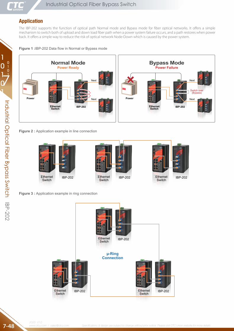
Figure 2 : Application example in line connection
IBP-202
IBP-202
IBP-202 IBP-202 IBP-202
IBP-202
µ-RingConnection
EthernetSwitch
EthernetSwitch
EthernetSwitch
EthernetSwitch
EthernetSwitch
EthernetSwitch
Bypass ModePower Failure
Normal ModePower Ready
IBP-202
Power
EthernetSwitch
Next
Next
Next
Next
IBP-202
Power
EthernetSwitch
Switch over(Bypass)
Figure 1 :IBP-202 Data flow in Normal or Bypass mode
IBP-202
IBP-202
IBP-202 IBP-202 IBP-202
IBP-202
µ-RingConnection
EthernetSwitch
EthernetSwitch
EthernetSwitch
EthernetSwitch
EthernetSwitch
EthernetSwitch
Figure 3 : Application example in ring connection
Industrial Optical Fiber Bypass Switch
Industrial O
ptical Fiber Bypass Switch IBP-202
ApplicationThe IBP-202 supports the function of optical path Normal mode and Bypass mode for fiber optical networks. It offers a simple mechanism to switch both of upload and down load fiber path when a power system failure occurs, and a path restores when power back. It offers a simple way to reduce the risk of optical network Node-Down which is caused by the power system.

10101
0101
R
Specifications & design are subject to change without prior notice. Please visit CTC Union website for more details. www.ctcu.com / [email protected] V1.0
7
7-49
Industrial Optical Fiber Bypass Switch
Dimensions
IBP-202 SC Type
9.4
14.913
5.00
15.20
62.50
30.48
106.0050.00
184.
30
54.00
50.5
3
IBP-202 LC Type
15.2
12.5
135.
00
15.20
62.50
30.48
106.0050.00
184.
30
54.00
50.5
3
IBP-202 ST Type
9.4
15.9
135.
00
15.20
62.50
30.48
106.0050.00
184.
30
54.00
50.5
3
Side View Front View Rear View DIN-Rail Kit View Wall-Mount Kit View
Side View Front View Rear View DIN-Rail Kit View Wall-Mount Kit View
Side View Front View Rear View DIN-Rail Kit View Wall-Mount Kit View
IBP-202 SC Type
9.4
14.9
135.
00
15.20
62.50
30.48
106.0050.00
184.
30
54.00
50.5
3
IBP-202 LC Type
15.2
12.5
135.
00
15.20
62.50
30.48
106.0050.00
184.
30
54.00
50.5
3
IBP-202 ST Type
9.4
15.9
135.
00
15.20
62.50
30.48
106.0050.00
184.
30
54.00
50.5
3
Side View Front View Rear View DIN-Rail Kit View Wall-Mount Kit View
Side View Front View Rear View DIN-Rail Kit View Wall-Mount Kit View
Side View Front View Rear View DIN-Rail Kit View Wall-Mount Kit View
IBP-202 SC Type
IBP-202 LC Type
IBP-202 ST Type
(Optional accessory)
(Optional accessory)
(Optional accessory)
Industrial Optical Fiber Bypass SwitchInd
ustrial Optical Fiber Bypass Sw
itch IBP-202
R
Specifications & design are subject to change without prior notice. Please visit CTC Union website for more details. www.ctcu.com / [email protected]
2020 V1.0
10101
0101
7
7-50
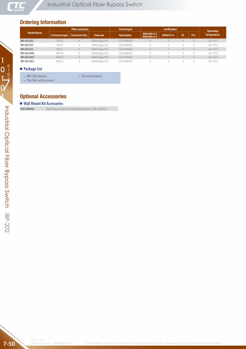
Ordering Information
Model NameFiber connector Power Input Certification Operating
TemperatureConnector type Connector Q'ty Data rate Redundant EN61000-6-2EN61000-6-4 EN50121-4 CE FCC
IBP-202-SSC SM SC 4 100M/Giga/10G 12/24/48VDC V V V V -20~70˚C
IBP-202-SST SM ST 4 100M/Giga/10G 12/24/48VDC V V V V -20~70˚C
IBP-202-SLC SM LC 4 100M/Giga/10G 12/24/48VDC V V V V -20~70˚CIBP-202-MSC MM SC 4 100M/Giga/10G 12/24/48VDC V V V V -20~70˚CIBP-202-MST MM ST 4 100M/Giga/10G 12/24/48VDC V V V V -20~70˚CIBP-202-MLC MM LC 4 100M/Giga/10G 12/24/48VDC V V V V -20~70˚C
Optional Accessories
IND-WMK02 Wall Mount kit for Industrial product, 184 x 50mm
Wall Mount Kit Accessories
Package List
• IBP-202device• DinRailwithscrews
• Terminalblock
Industrial Optical Fiber Bypass Switch
Industrial O
ptical Fiber Bypass Switch IBP-202