ic rf test report - texas instruments wikiprocessors.wiki.ti.com/images/8/81/cr3n2752atx_r01... ·...
TRANSCRIPT

SPORTON INTERNATIONAL INC. Page Number : 1 of 72
TEL : 886-3-327-3456 Report Issued Date : Jan. 22, 2014
FAX : 886-3-328-4978 Report Version : Rev. 01
IC : 451I-WL1835COM
IC RF Test Report Report No. : CR3N2752ATX
IC RF Test Report
APPLICANT : Texas Instruments Incorporated
EQUIPMENT : WiFi and Bluetooth Evaluation Board
BRAND NAME : Texas Instruments
MODEL NAME : WL1835MODCOM8B
IC : 451I-WL1835COM
STANDARD : IC RSS-210 issue 8
The product was received on Nov. 27, 2013 and testing was completed on Dec. 12, 2013. We,
SPORTON INTERNATIONAL INC., would like to declare that the tested sample has been
evaluated in accordance with the procedures and shown to be compliant with the applicable
technical standards.
The test results in this report apply exclusively to the tested model / sample. Without written
approval of SPORTON INTERNATIONAL INC., the test report shall not be reproduced except
in full.
Reviewed by: Joseph Lin / Supervisor
Approved by: Jones Tsai / Manager
SPORTON INTERNATIONAL INC. No. 52, Hwa Ya 1st Rd., Hwa Ya Technology Park, Kwei-Shan Hsiang, Tao Yuan Hsien, Taiwan, R.O.C.
SPORTON INTERNATIONAL INC. Page Number : 2 of 72
TEL : 886-3-327-3456 Report Issued Date : Jan. 22, 2014
FAX : 886-3-328-4978 Report Version : Rev. 01
IC : 451I-WL1835COM
IC RF Test Report Report No. : CR3N2752ATX
TABLE OF CONTENTS REVISION HISTORY .......................................................................................................................................... 3
SUMMARY OF TEST RESULT ......................................................................................................................... 4
1 GENERAL DESCRIPTION .......................................................................................................................... 5
1.1 Applicant ............................................................................................................................................ 5
1.2 Manufacturer ...................................................................................................................................... 5 1.3 Feature of Equipment Under Test ..................................................................................................... 5 1.4 Product Specification of Equipment Under Test ................................................................................ 5 1.5 Modification of EUT ........................................................................................................................... 6 1.6 Testing Site ........................................................................................................................................ 6 1.7 Applied Standards ............................................................................................................................. 6
2 TEST CONFIGURATION OF EQUIPMENT UNDER TEST ........................................................................ 7
2.1 Descriptions of Test Mode ................................................................................................................. 7 2.2 Test Mode .......................................................................................................................................... 8 2.3 Connection Diagram of Test System ................................................................................................. 9
2.4 Support Unit used in test configuration and system ........................................................................ 10 2.5 EUT Operation Test Setup .............................................................................................................. 10 2.6 Measurement Results Explanation Example ................................................................................... 10
3 TEST RESULT .......................................................................................................................................... 11
3.1 Number of Channel Measurement .................................................................................................. 11 3.2 Hopping Channel Separation Measurement ................................................................................... 13
3.3 Dwell Time Measurement ................................................................................................................ 20 3.4 20dB and 99% Bandwidth Measurement ........................................................................................ 23 3.5 Peak Output Power Measurement .................................................................................................. 36 3.6 Conducted Band Edges Measurement............................................................................................ 38
3.7 Conducted Spurious Emission Measurement ................................................................................. 45 3.8 Radiated Band Edges and Spurious Emission Measurement ........................................................ 55 3.9 AC Conducted Emission Measurement........................................................................................... 66 3.10 Antenna Requirements .................................................................................................................... 70
4 LIST OF MEASURING EQUIPMENT ........................................................................................................ 71
5 UNCERTAINTY OF EVALUATION ........................................................................................................... 72
APPENDIX A. SETUP PHOTOGRAPHS
SPORTON INTERNATIONAL INC. Page Number : 3 of 72
TEL : 886-3-327-3456 Report Issued Date : Jan. 22, 2014
FAX : 886-3-328-4978 Report Version : Rev. 01
IC : 451I-WL1835COM
IC RF Test Report Report No. : CR3N2752ATX
REVISION HISTORY
REPORT NO. VERSION DESCRIPTION ISSUED DATE
CR3N2752ATX Rev. 01 Initial issue of report Jan. 22, 2014
SPORTON INTERNATIONAL INC. Page Number : 4 of 72
TEL : 886-3-327-3456 Report Issued Date : Jan. 22, 2014
FAX : 886-3-328-4978 Report Version : Rev. 01
IC : 451I-WL1835COM
IC RF Test Report Report No. : CR3N2752ATX
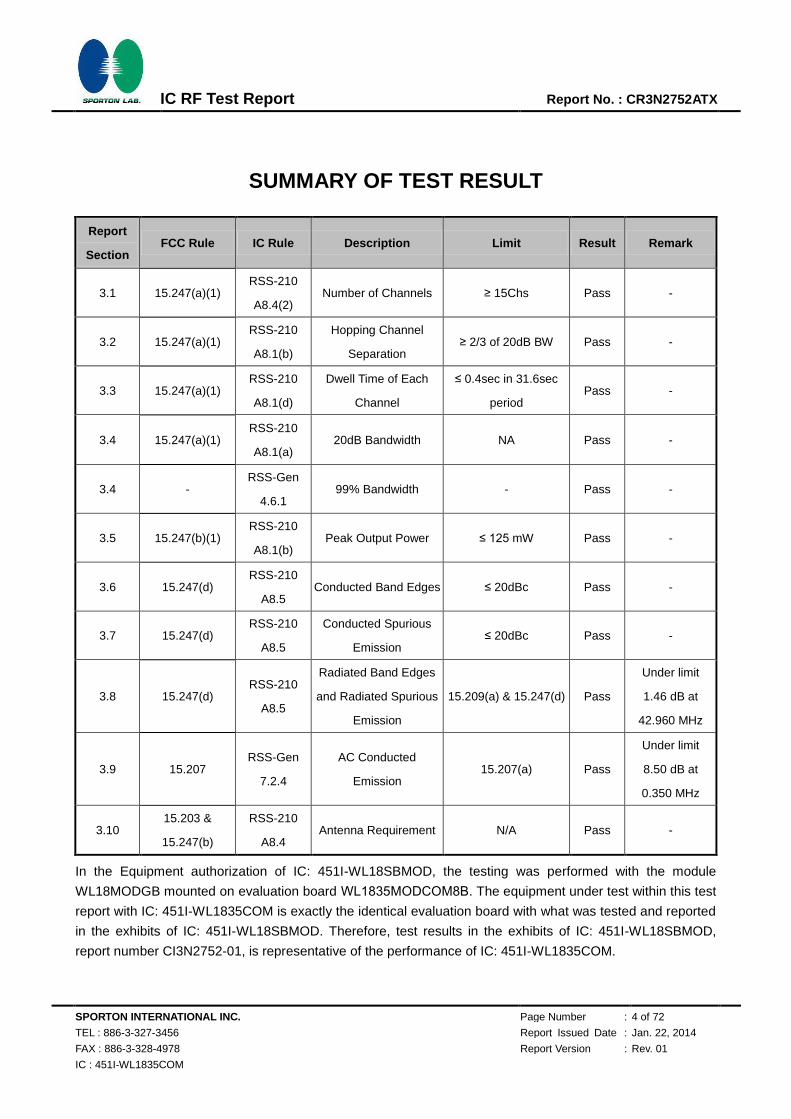
SUMMARY OF TEST RESULT
Report
Section FCC Rule IC Rule Description Limit Result Remark
3.1 15.247(a)(1) RSS-210
A8.4(2) Number of Channels ≥ 15Chs Pass -
3.2 15.247(a)(1) RSS-210
A8.1(b)
Hopping Channel
Separation ≥ 2/3 of 20dB BW Pass -
3.3 15.247(a)(1) RSS-210
A8.1(d)
Dwell Time of Each
Channel
≤ 0.4sec in 31.6sec
period Pass -
3.4 15.247(a)(1) RSS-210
A8.1(a) 20dB Bandwidth NA Pass -
3.4 - RSS-Gen
4.6.1 99% Bandwidth - Pass -
3.5 15.247(b)(1) RSS-210
A8.1(b) Peak Output Power ≤ 125 mW Pass -
3.6 15.247(d) RSS-210
A8.5 Conducted Band Edges ≤ 20dBc Pass -
3.7 15.247(d) RSS-210
A8.5
Conducted Spurious
Emission ≤ 20dBc Pass -
3.8 15.247(d) RSS-210
A8.5
Radiated Band Edges
and Radiated Spurious
Emission
15.209(a) & 15.247(d) Pass
Under limit
1.46 dB at
42.960 MHz
3.9 15.207 RSS-Gen
7.2.4
AC Conducted
Emission 15.207(a) Pass
Under limit
8.50 dB at
0.350 MHz
3.10 15.203 &
15.247(b)
RSS-210
A8.4 Antenna Requirement N/A Pass -
In the Equipment authorization of IC: 451I-WL18SBMOD, the testing was performed with the module
WL18MODGB mounted on evaluation board WL1835MODCOM8B. The equipment under test within this test
report with IC: 451I-WL1835COM is exactly the identical evaluation board with what was tested and reported
in the exhibits of IC: 451I-WL18SBMOD. Therefore, test results in the exhibits of IC: 451I-WL18SBMOD,
report number CI3N2752-01, is representative of the performance of IC: 451I-WL1835COM.
SPORTON INTERNATIONAL INC. Page Number : 5 of 72
TEL : 886-3-327-3456 Report Issued Date : Jan. 22, 2014
FAX : 886-3-328-4978 Report Version : Rev. 01
IC : 451I-WL1835COM
IC RF Test Report Report No. : CR3N2752ATX
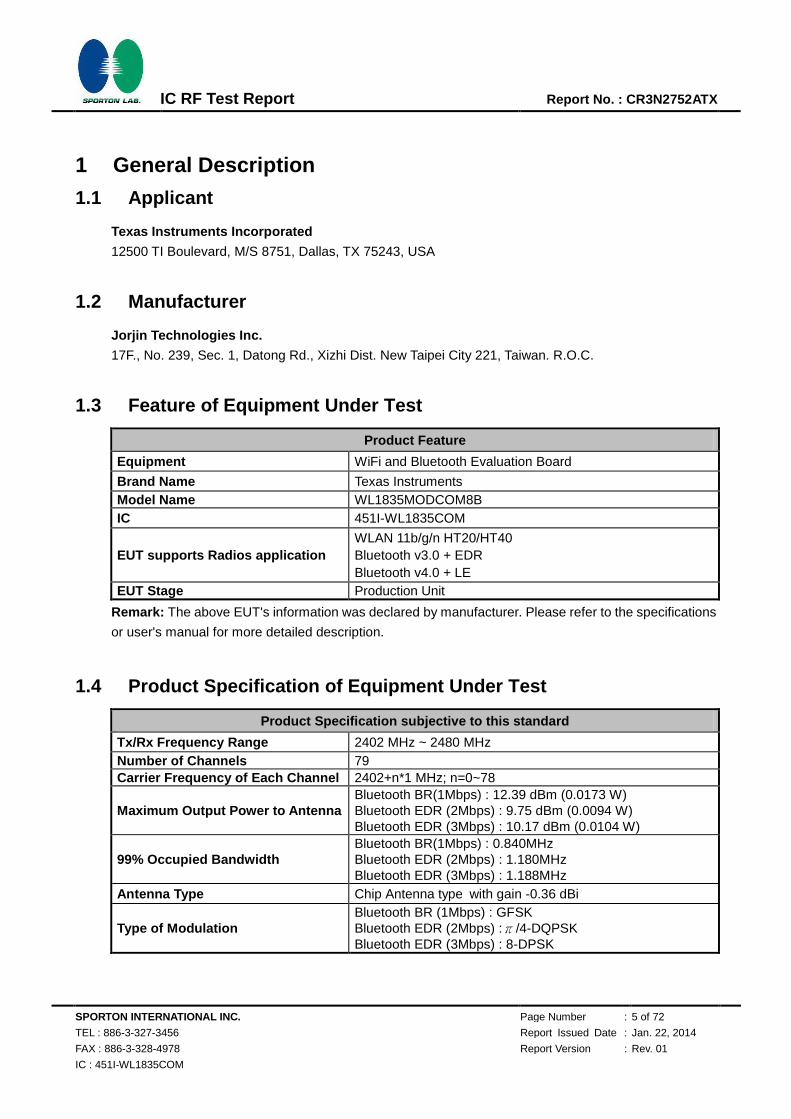
1 General Description
1.1 Applicant
Texas Instruments Incorporated
12500 TI Boulevard, M/S 8751, Dallas, TX 75243, USA
1.2 Manufacturer
Jorjin Technologies Inc.
17F., No. 239, Sec. 1, Datong Rd., Xizhi Dist. New Taipei City 221, Taiwan. R.O.C.
1.3 Feature of Equipment Under Test
Product Feature
Equipment WiFi and Bluetooth Evaluation Board
Brand Name Texas Instruments Model Name WL1835MODCOM8B IC 451I-WL1835COM
EUT supports Radios application WLAN 11b/g/n HT20/HT40 Bluetooth v3.0 + EDR Bluetooth v4.0 + LE
EUT Stage Production Unit
Remark: The above EUT's information was declared by manufacturer. Please refer to the specifications
or user's manual for more detailed description.
1.4 Product Specification of Equipment Under Test
Product Specification subjective to this standard
Tx/Rx Frequency Range 2402 MHz ~ 2480 MHz Number of Channels 79 Carrier Frequency of Each Channel 2402+n*1 MHz; n=0~78
Maximum Output Power to Antenna Bluetooth BR(1Mbps) : 12.39 dBm (0.0173 W) Bluetooth EDR (2Mbps) : 9.75 dBm (0.0094 W) Bluetooth EDR (3Mbps) : 10.17 dBm (0.0104 W)
99% Occupied Bandwidth Bluetooth BR(1Mbps) : 0.840MHz Bluetooth EDR (2Mbps) : 1.180MHz Bluetooth EDR (3Mbps) : 1.188MHz
Antenna Type Chip Antenna type with gain -0.36 dBi
Type of Modulation Bluetooth BR (1Mbps) : GFSK Bluetooth EDR (2Mbps) :π/4-DQPSK Bluetooth EDR (3Mbps) : 8-DPSK
SPORTON INTERNATIONAL INC. Page Number : 6 of 72
TEL : 886-3-327-3456 Report Issued Date : Jan. 22, 2014
FAX : 886-3-328-4978 Report Version : Rev. 01
IC : 451I-WL1835COM
IC RF Test Report Report No. : CR3N2752ATX
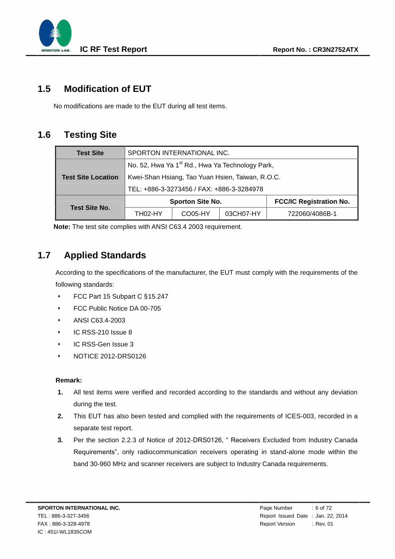
1.5 Modification of EUT
No modifications are made to the EUT during all test items.
1.6 Testing Site
Test Site SPORTON INTERNATIONAL INC.
Test Site Location
No. 52, Hwa Ya 1st Rd., Hwa Ya Technology Park,
Kwei-Shan Hsiang, Tao Yuan Hsien, Taiwan, R.O.C.
TEL: +886-3-3273456 / FAX: +886-3-3284978
Test Site No. Sporton Site No. FCC/IC Registration No.
TH02-HY CO05-HY 03CH07-HY 722060/4086B-1
Note: The test site complies with ANSI C63.4 2003 requirement.
1.7 Applied Standards
According to the specifications of the manufacturer, the EUT must comply with the requirements of the
following standards:
FCC Part 15 Subpart C §15.247
FCC Public Notice DA 00-705
ANSI C63.4-2003
IC RSS-210 Issue 8
IC RSS-Gen Issue 3
NOTICE 2012-DRS0126
Remark:
1. All test items were verified and recorded according to the standards and without any deviation
during the test.
2. This EUT has also been tested and complied with the requirements of ICES-003, recorded in a
separate test report.
3. Per the section 2.2.3 of Notice of 2012-DRS0126, “ Receivers Excluded from Industry Canada
Requirements”, only radiocommunication receivers operating in stand-alone mode within the
band 30-960 MHz and scanner receivers are subject to Industry Canada requirements.
SPORTON INTERNATIONAL INC. Page Number : 7 of 72
TEL : 886-3-327-3456 Report Issued Date : Jan. 22, 2014
FAX : 886-3-328-4978 Report Version : Rev. 01
IC : 451I-WL1835COM
IC RF Test Report Report No. : CR3N2752ATX
2 Test Configuration of Equipment Under Test
2.1 Descriptions of Test Mode
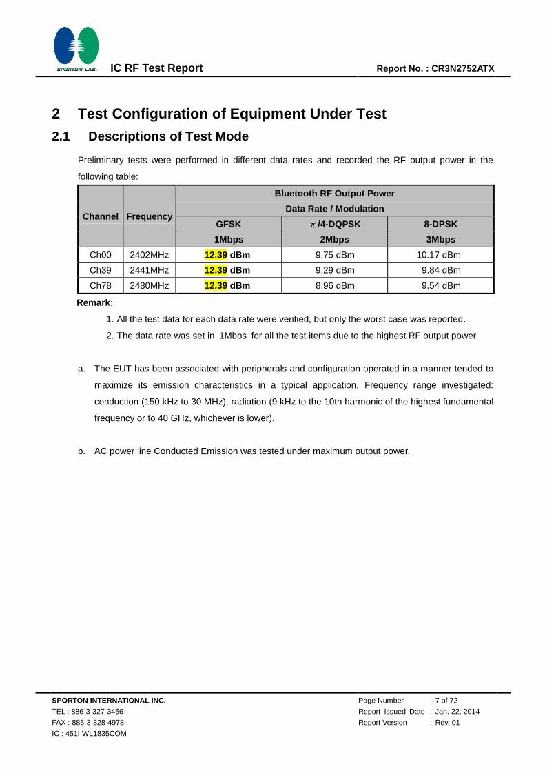
Preliminary tests were performed in different data rates and recorded the RF output power in the
following table:
Channel Frequency
Bluetooth RF Output Power
Data Rate / Modulation
GFSK π/4-DQPSK 8-DPSK
1Mbps 2Mbps 3Mbps
Ch00 2402MHz 12.39 dBm 9.75 dBm 10.17 dBm
Ch39 2441MHz 12.39 dBm 9.29 dBm 9.84 dBm
Ch78 2480MHz 12.39 dBm 8.96 dBm 9.54 dBm
Remark:
1. All the test data for each data rate were verified, but only the worst case was reported.
2. The data rate was set in 1Mbps for all the test items due to the highest RF output power.
a. The EUT has been associated with peripherals and configuration operated in a manner tended to
maximize its emission characteristics in a typical application. Frequency range investigated:
conduction (150 kHz to 30 MHz), radiation (9 kHz to the 10th harmonic of the highest fundamental
frequency or to 40 GHz, whichever is lower).
b. AC power line Conducted Emission was tested under maximum output power.

SPORTON INTERNATIONAL INC. Page Number : 8 of 72
TEL : 886-3-327-3456 Report Issued Date : Jan. 22, 2014
FAX : 886-3-328-4978 Report Version : Rev. 01
IC : 451I-WL1835COM
IC RF Test Report Report No. : CR3N2752ATX
2.2 Test Mode
The following summary table is showing all test modes to demonstrate in compliance with the standard.
Summary table of Test Cases
Test Item
Data Rate / Modulation
Bluetooth BR 1Mbps
GFSK
Bluetooth EDR 2Mbps
π/4-DQPSK
Bluetooth EDR 3Mbps
8-DPSK
Conducted
Test Cases
Mode 1: CH00_2402 MHz
Mode 2: CH39_2441 MHz
Mode 3: CH78_2480 MHz
Mode 4: CH00_2402 MHz
Mode 5: CH39_2441 MHz
Mode 6: CH78_2480 MHz
Mode 7: CH00_2402 MHz
Mode 8: CH39_2441 MHz
Mode 9: CH78_2480 MHz
Radiated
Test Cases
Bluetooth BR 1Mbps GFSK
Mode 1: CH00_2402 MHz
Mode 2: CH39_2441 MHz
Mode 3: CH78_2480 MHz
AC
Conducted
Emission
Mode 1 : WLAN Link + Bluetooth Link + Adapter
Remark: For radiated test cases, the worst mode data rate 1Mbps was reported only, because this
data rate has the highest RF output power at preliminary tests, and the conducted spurious
emissions and conducted band edge measurement for each data rate are no worse than
1Mbps, and no other significantly frequencies found in conducted spurious emission.
SPORTON INTERNATIONAL INC. Page Number : 9 of 72
TEL : 886-3-327-3456 Report Issued Date : Jan. 22, 2014
FAX : 886-3-328-4978 Report Version : Rev. 01
IC : 451I-WL1835COM
IC RF Test Report Report No. : CR3N2752ATX
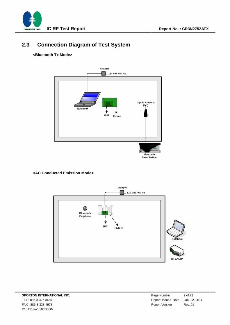
2.3 Connection Diagram of Test System
<Bluetooth Tx Mode>
Bluetooth Base Station
Dipole Antenna
Fixture
Notebook
Adapter
120 Vac / 60 Hz
EUT
<AC Conducted Emission Mode>
Adapter
120 Vac / 60 Hz
BluetoothEarphone
WLAN AP
EUTFixture
EUT
Notebook

SPORTON INTERNATIONAL INC. Page Number : 10 of 72
TEL : 886-3-327-3456 Report Issued Date : Jan. 22, 2014
FAX : 886-3-328-4978 Report Version : Rev. 01
IC : 451I-WL1835COM
IC RF Test Report Report No. : CR3N2752ATX
2.4 Support Unit used in test configuration and system
Item Equipment Trade Name Model Name FCC ID Data Cable Power Cord
1. Bluetooth Base Station R&S CBT32 N/A N/A Unshielded, 1.8 m
2. Bluetooth Earphone SonyErricsson MW600 PY700A2029 N/A N/A
3. WLAN AP D-Link DIR-628 KA2DIR628A2 N/A Unshielded, 1.8 m
4. Notebook DELL Vostro 1320 FCC DoC N/A
AC I/P:
Unshielded, 1.2 m
DC O/P:
Shielded, 1.8 m
5. Notebook DELL Latitude E6320 FCC DoC N/A
AC I/P:
Unshielded, 1.2 m
DC O/P:
Shielded, 1.8 m
6. Fixture N/A WG7XXXT01 N/A N/A N/A
7. Adapter Aviv Energy HK-IP15-A05 N/A N/A Unshielded, 1.8 m
2.5 EUT Operation Test Setup
For Bluetooth function, the RF utility, “HCT Tester” was installed in notebook which was programmed in
order to make the EUT get into the engineering modes to contact with Bluetooth base station for
continuous transmitting and receiving signals.
2.6 Measurement Results Explanation Example
For all conducted test items:
The offset level is set in the spectrum analyzer to compensate the RF cable loss and attenuator factor
between EUT conducted output port and spectrum analyzer. With the offset compensation, the
spectrum analyzer reading level is exactly the EUT RF output level. Example:
The spectrum analyzer offset is derived from RF cable loss and attenuator factor.
Offset = RF cable loss + attenuator factor.
Following shows an offset computation example with cable loss 4.2 dB and 10dB attenuator.
Offset(dB) = RF cable loss(dB) + attenuator factor(dB).
= 4.2 + 10 = 14.2 (dB)
SPORTON INTERNATIONAL INC. Page Number : 11 of 72
TEL : 886-3-327-3456 Report Issued Date : Jan. 22, 2014
FAX : 886-3-328-4978 Report Version : Rev. 01
IC : 451I-WL1835COM
IC RF Test Report Report No. : CR3N2752ATX
3 Test Result
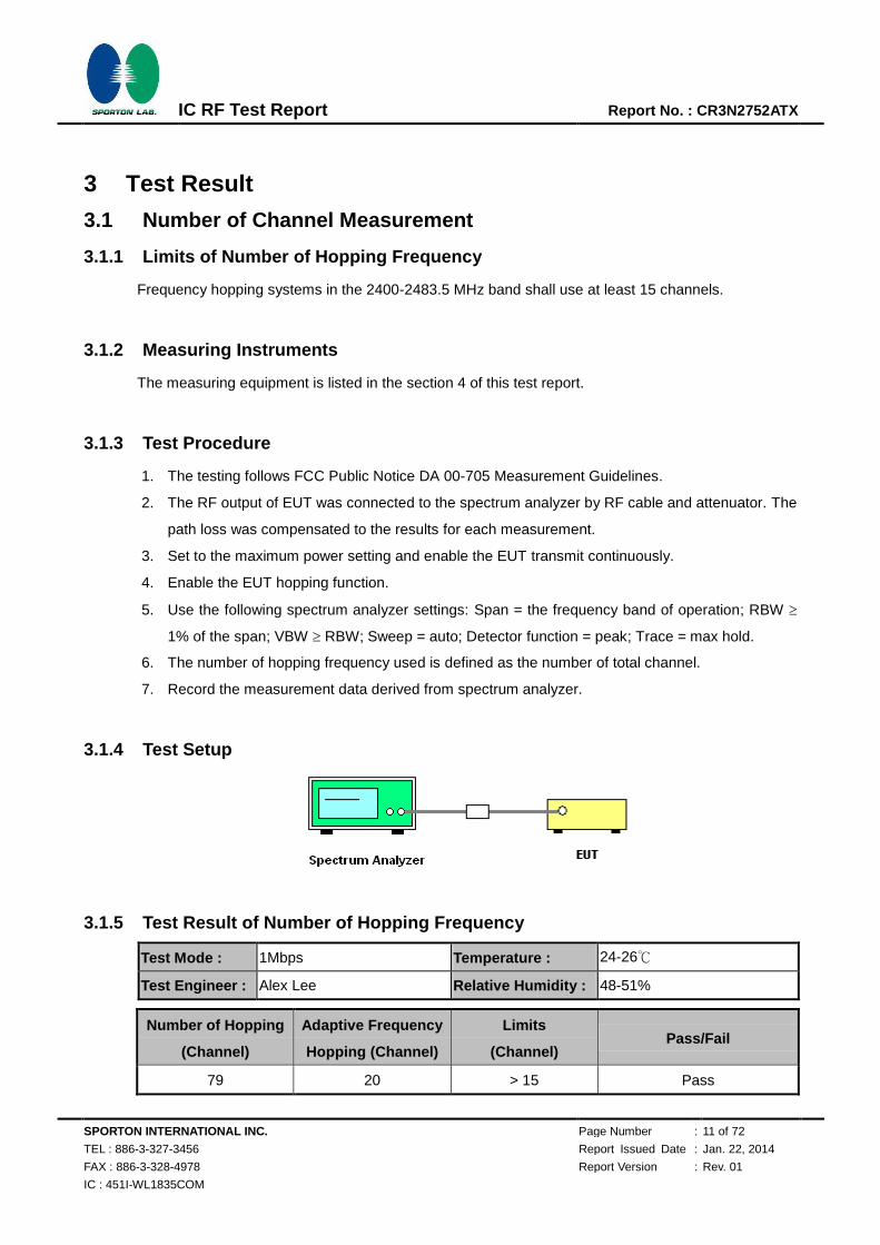
3.1 Number of Channel Measurement
3.1.1 Limits of Number of Hopping Frequency
Frequency hopping systems in the 2400-2483.5 MHz band shall use at least 15 channels.
3.1.2 Measuring Instruments
The measuring equipment is listed in the section 4 of this test report.
3.1.3 Test Procedure
1. The testing follows FCC Public Notice DA 00-705 Measurement Guidelines.
2. The RF output of EUT was connected to the spectrum analyzer by RF cable and attenuator. The
path loss was compensated to the results for each measurement.
3. Set to the maximum power setting and enable the EUT transmit continuously.
4. Enable the EUT hopping function.
5. Use the following spectrum analyzer settings: Span = the frequency band of operation; RBW
1% of the span; VBW RBW; Sweep = auto; Detector function = peak; Trace = max hold.
6. The number of hopping frequency used is defined as the number of total channel.
7. Record the measurement data derived from spectrum analyzer.
3.1.4 Test Setup
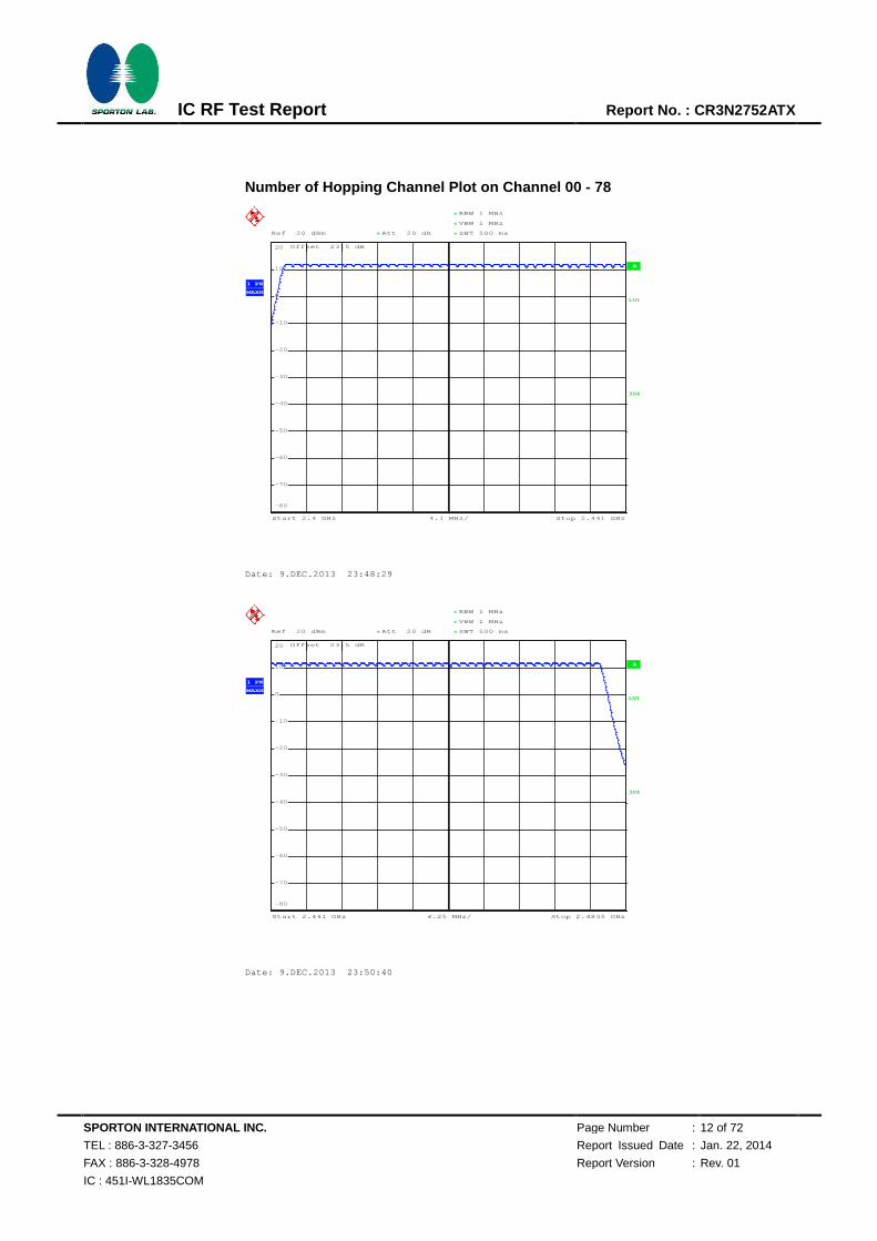
3.1.5 Test Result of Number of Hopping Frequency
Test Mode : 1Mbps Temperature : 24-26℃
Test Engineer : Alex Lee Relative Humidity : 48-51%
Number of Hopping
(Channel)
Adaptive Frequency
Hopping (Channel)
Limits
(Channel) Pass/Fail
79 20 > 15 Pass
SPORTON INTERNATIONAL INC. Page Number : 12 of 72
TEL : 886-3-327-3456 Report Issued Date : Jan. 22, 2014
FAX : 886-3-328-4978 Report Version : Rev. 01
IC : 451I-WL1835COM
IC RF Test Report Report No. : CR3N2752ATX
Number of Hopping Channel Plot on Channel 00 - 78
A
Offset 23.5 dB
LVL
Ref 20 dBm Att 20 dB **
4.1 MHz/Start 2.4 GHz Stop 2.441 GHz
*
*
3DB
RBW 1 MHz
VBW 1 MHz
SWT 500 ms*
1 PK
MAXH
-80
-70
-60
-50
-40
-30
-20
-10
0
10
20
Date: 9.DEC.2013 23:48:29
Ref 20 dBm Att 20 dB **
*
Offset 23.5 dB
A
LVL
3DB
RBW 1 MHz
VBW 1 MHz
SWT 500 ms
*
Start 2.441 GHz Stop 2.4835 GHz4.25 MHz/
*
1 PK
MAXH
-80
-70
-60
-50
-40
-30
-20
-10
0
10
20
Date: 9.DEC.2013 23:50:40
720510
SPORTON INTERNATIONAL INC. Page Number : 13 of 72
TEL : 886-3-327-3456 Report Issued Date : Jan. 22, 2014
FAX : 886-3-328-4978 Report Version : Rev. 01
IC : 451I-WL1835COM
IC RF Test Report Report No. : CR3N2752ATX
3.2 Hopping Channel Separation Measurement
3.2.1 Limit of Hopping Channel Separation
Frequency hopping systems operating in the 2400-2483.5 MHz band may have hopping channel
carrier frequencies that are separated by 25 kHz or two-thirds of the 20 dB bandwidth of the hopping
channel, whichever is greater.
3.2.2 Measuring Instruments
The measuring equipment is listed in the section 4 of this test report.
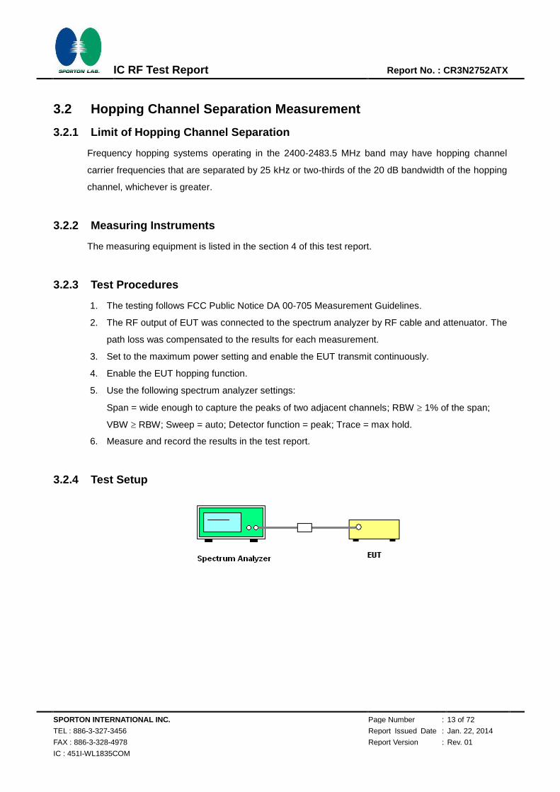
3.2.3 Test Procedures
1. The testing follows FCC Public Notice DA 00-705 Measurement Guidelines.
2. The RF output of EUT was connected to the spectrum analyzer by RF cable and attenuator. The
path loss was compensated to the results for each measurement.
3. Set to the maximum power setting and enable the EUT transmit continuously.
4. Enable the EUT hopping function.
5. Use the following spectrum analyzer settings:
Span = wide enough to capture the peaks of two adjacent channels; RBW 1% of the span;
VBW RBW; Sweep = auto; Detector function = peak; Trace = max hold.
6. Measure and record the results in the test report.
3.2.4 Test Setup
SPORTON INTERNATIONAL INC. Page Number : 14 of 72
TEL : 886-3-327-3456 Report Issued Date : Jan. 22, 2014
FAX : 886-3-328-4978 Report Version : Rev. 01
IC : 451I-WL1835COM
IC RF Test Report Report No. : CR3N2752ATX
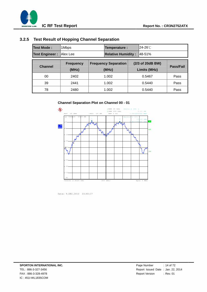
3.2.5 Test Result of Hopping Channel Separation
Test Mode : 1Mbps Temperature : 24-26℃
Test Engineer : Alex Lee Relative Humidity : 48-51%
Channel Frequency
(MHz)
Frequency Separation
(MHz)
(2/3 of 20dB BW)
Limits (MHz) Pass/Fail
00 2402 1.002 0.5467 Pass
39 2441 1.002 0.5440 Pass
78 2480 1.002 0.5440 Pass
Channel Separation Plot on Channel 00 - 01
Ref 20 dBm Att 20 dB*
*
*
Offset 23.5 dB
1 PK
MAXH
A
LVL
3DB
RBW 30 kHz
VBW 100 kHz
SWT 5 ms
Center 2.4025 GHz Span 3 MHz300 kHz/
-80
-70
-60
-50
-40
-30
-20
-10
0
10
20
1
Marker 1 [T1 ]
11.43 dBm
2.401996000 GHz
2
Delta 2 [T1 ]
0.10 dB
1.002000000 MHz
Date: 9.DEC.2013 23:40:17
720510

SPORTON INTERNATIONAL INC. Page Number : 15 of 72
TEL : 886-3-327-3456 Report Issued Date : Jan. 22, 2014
FAX : 886-3-328-4978 Report Version : Rev. 01
IC : 451I-WL1835COM
IC RF Test Report Report No. : CR3N2752ATX
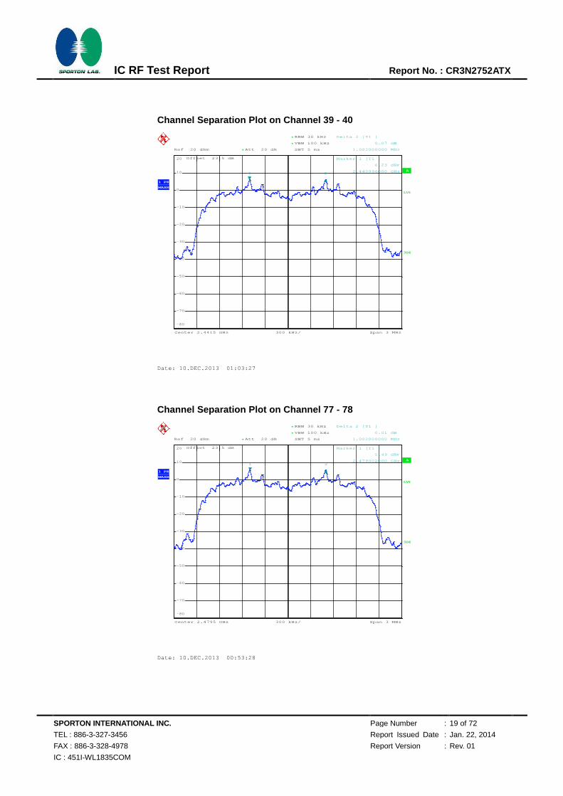
Channel Separation Plot on Channel 39 - 40
Channel Separation Plot on Channel 77 - 78
Ref 20 dBm Att 20 dB*
*
*
Offset 23.5 dB
1 PK
MAXH
A
LVL
3DB
RBW 30 kHz
VBW 100 kHz
SWT 5 ms
Center 2.4415 GHz Span 3 MHz300 kHz/
-80
-70
-60
-50
-40
-30
-20
-10
0
10
20
1
Marker 1 [T1 ]
11.34 dBm
2.440996000 GHz
2
Delta 2 [T1 ]
-0.01 dB
1.002000000 MHz
Date: 9.DEC.2013 23:58:12
Ref 20 dBm Att 20 dB*
*
*
Offset 23.5 dB
1 PK
MAXH
A
LVL
3DB
RBW 30 kHz
VBW 100 kHz
SWT 5 ms
Center 2.4795 GHz Span 3 MHz300 kHz/
-80
-70
-60
-50
-40
-30
-20
-10
0
10
20
1
Marker 1 [T1 ]
11.16 dBm
2.479002000 GHz
2
Delta 2 [T1 ]
-0.05 dB
1.002000000 MHz
Date: 10.DEC.2013 00:08:17
720510
720510

SPORTON INTERNATIONAL INC. Page Number : 16 of 72
TEL : 886-3-327-3456 Report Issued Date : Jan. 22, 2014
FAX : 886-3-328-4978 Report Version : Rev. 01
IC : 451I-WL1835COM
IC RF Test Report Report No. : CR3N2752ATX
Test Mode : 2Mbps Temperature : 24-26℃
Test Engineer : Alex Lee Relative Humidity : 48-51%
Channel Frequency
(MHz)
Frequency Separation
(MHz)
(2/3 of 20dB BW)
Limits (MHz) Pass/Fail
00 2402 1.002 0.8520 Pass
39 2441 1.002 0.8520 Pass
78 2480 1.002 0.8520 Pass
Channel Separation Plot on Channel 00 - 01
Ref 20 dBm Att 20 dB*
*
*
Offset 23.5 dB
1 PK
MAXH
A
LVL
3DB
RBW 30 kHz
VBW 100 kHz
SWT 5 ms
Center 2.4025 GHz Span 3 MHz300 kHz/
-80
-70
-60
-50
-40
-30
-20
-10
0
10
20
1
Marker 1 [T1 ]
6.95 dBm
2.401996000 GHz2
Delta 2 [T1 ]
0.06 dB
1.002000000 MHz
Date: 10.DEC.2013 00:18:05
720510

SPORTON INTERNATIONAL INC. Page Number : 17 of 72
TEL : 886-3-327-3456 Report Issued Date : Jan. 22, 2014
FAX : 886-3-328-4978 Report Version : Rev. 01
IC : 451I-WL1835COM
IC RF Test Report Report No. : CR3N2752ATX
Channel Separation Plot on Channel 39 - 40
Channel Separation Plot on Channel 77 - 78
Ref 20 dBm Att 20 dB*
*
*
Offset 23.5 dB
1 PK
MAXH
A
LVL
3DB
RBW 30 kHz
VBW 100 kHz
SWT 5 ms
Center 2.4415 GHz Span 3 MHz300 kHz/
-80
-70
-60
-50
-40
-30
-20
-10
0
10
20
1
Marker 1 [T1 ]
6.19 dBm
2.441002000 GHz2
Delta 2 [T1 ]
-0.03 dB
1.002000000 MHz
Date: 10.DEC.2013 00:28:49
Ref 20 dBm Att 20 dB*
*
*
Offset 23.5 dB
1 PK
MAXH
A
LVL
3DB
RBW 30 kHz
VBW 100 kHz
SWT 5 ms
Center 2.4795 GHz Span 3 MHz300 kHz/
-80
-70
-60
-50
-40
-30
-20
-10
0
10
20
1
Marker 1 [T1 ]
5.54 dBm
2.479002000 GHz2
Delta 2 [T1 ]
-0.07 dB
1.002000000 MHz
Date: 10.DEC.2013 00:50:56
720510
720510
SPORTON INTERNATIONAL INC. Page Number : 18 of 72
TEL : 886-3-327-3456 Report Issued Date : Jan. 22, 2014
FAX : 886-3-328-4978 Report Version : Rev. 01
IC : 451I-WL1835COM
IC RF Test Report Report No. : CR3N2752ATX
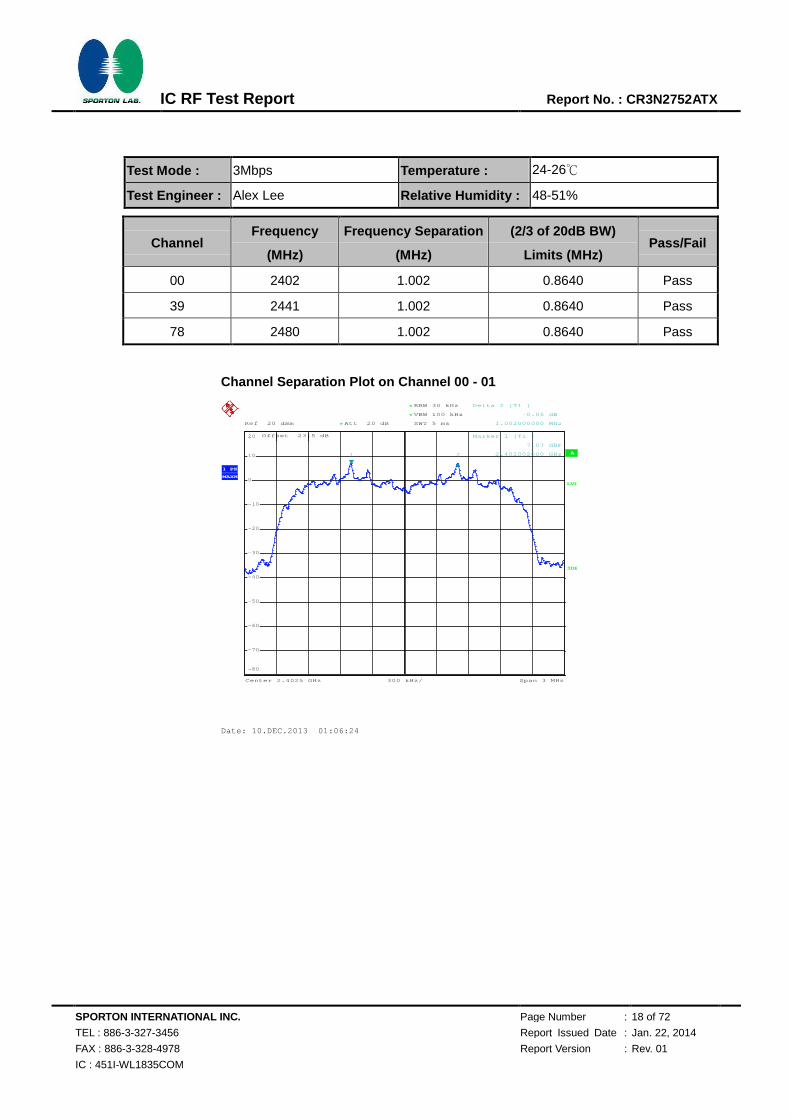
Test Mode : 3Mbps Temperature : 24-26℃
Test Engineer : Alex Lee Relative Humidity : 48-51%
Channel Frequency
(MHz)
Frequency Separation
(MHz)
(2/3 of 20dB BW)
Limits (MHz) Pass/Fail
00 2402 1.002 0.8640 Pass
39 2441 1.002 0.8640 Pass
78 2480 1.002 0.8640 Pass
Channel Separation Plot on Channel 00 - 01
Ref 20 dBm Att 20 dB*
*
*
Offset 23.5 dB
1 PK
MAXH
A
LVL
3DB
RBW 30 kHz
VBW 100 kHz
SWT 5 ms
Center 2.4025 GHz Span 3 MHz300 kHz/
-80
-70
-60
-50
-40
-30
-20
-10
0
10
20
1
Marker 1 [T1 ]
7.07 dBm
2.402002000 GHz2
Delta 2 [T1 ]
-0.05 dB
1.002000000 MHz
Date: 10.DEC.2013 01:06:24
720510
SPORTON INTERNATIONAL INC. Page Number : 19 of 72
TEL : 886-3-327-3456 Report Issued Date : Jan. 22, 2014
FAX : 886-3-328-4978 Report Version : Rev. 01
IC : 451I-WL1835COM
IC RF Test Report Report No. : CR3N2752ATX
Channel Separation Plot on Channel 39 - 40
Channel Separation Plot on Channel 77 - 78
Ref 20 dBm Att 20 dB*
*
*
Offset 23.5 dB
1 PK
MAXH
A
LVL
3DB
RBW 30 kHz
VBW 100 kHz
SWT 5 ms
Center 2.4415 GHz Span 3 MHz300 kHz/
-80
-70
-60
-50
-40
-30
-20
-10
0
10
20
1
Marker 1 [T1 ]
6.23 dBm
2.440996000 GHz2
Delta 2 [T1 ]
0.07 dB
1.002000000 MHz
Date: 10.DEC.2013 01:03:27
Ref 20 dBm Att 20 dB*
*
*
Offset 23.5 dB
1 PK
MAXH
A
LVL
3DB
RBW 30 kHz
VBW 100 kHz
SWT 5 ms
Center 2.4795 GHz Span 3 MHz300 kHz/
-80
-70
-60
-50
-40
-30
-20
-10
0
10
20
1
Marker 1 [T1 ]
5.49 dBm
2.479002000 GHz2
Delta 2 [T1 ]
0.01 dB
1.002000000 MHz
Date: 10.DEC.2013 00:53:28
720510
720510

SPORTON INTERNATIONAL INC. Page Number : 20 of 72
TEL : 886-3-327-3456 Report Issued Date : Jan. 22, 2014
FAX : 886-3-328-4978 Report Version : Rev. 01
IC : 451I-WL1835COM
IC RF Test Report Report No. : CR3N2752ATX
3.3 Dwell Time Measurement
3.3.1 Limit of Dwell Time
The average time of occupancy on any channel shall not be greater than 0.4 seconds within a period
of 0.4 seconds multiplied by the number of hopping channels employed.
3.3.2 Measuring Instruments
The measuring equipment is listed in the section 4 of this test report.
3.3.3 Test Procedures
1. The testing follows FCC Public Notice DA 00-705 Measurement Guidelines.
2. The RF output of EUT was connected to the spectrum analyzer by RF cable and attenuator.
The path loss was compensated to the results for each measurement.
3. Set to the maximum power setting and enable the EUT transmit continuously.
4. Enable the EUT hopping function.
5. Use the following spectrum analyzer settings: Span = zero span, centered on a hopping
channel; RBW = 1 MHz; VBW RBW; Sweep = as necessary to capture the entire dwell time
per hopping channel; Detector function = peak; Trace = max hold.
6. Measure and record the results in the test report.
3.3.4 Test Setup
SPORTON INTERNATIONAL INC. Page Number : 21 of 72
TEL : 886-3-327-3456 Report Issued Date : Jan. 22, 2014
FAX : 886-3-328-4978 Report Version : Rev. 01
IC : 451I-WL1835COM
IC RF Test Report Report No. : CR3N2752ATX
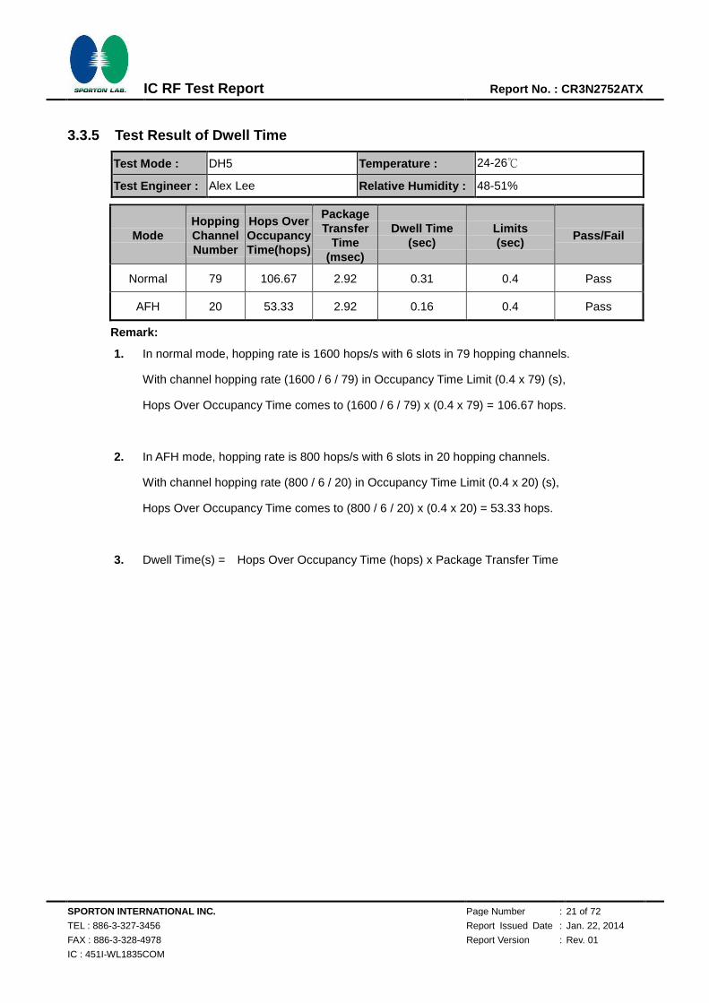
3.3.5 Test Result of Dwell Time
Test Mode : DH5 Temperature : 24-26℃
Test Engineer : Alex Lee Relative Humidity : 48-51%
Mode Hopping Channel Number
Hops Over Occupancy Time(hops)
Package Transfer
Time (msec)
Dwell Time (sec)
Limits (sec)
Pass/Fail
Normal 79 106.67 2.92 0.31 0.4 Pass
AFH 20 53.33 2.92 0.16 0.4 Pass
Remark:
1. In normal mode, hopping rate is 1600 hops/s with 6 slots in 79 hopping channels.
With channel hopping rate (1600 / 6 / 79) in Occupancy Time Limit (0.4 x 79) (s),
Hops Over Occupancy Time comes to (1600 / 6 / 79) x (0.4 x 79) = 106.67 hops.
2. In AFH mode, hopping rate is 800 hops/s with 6 slots in 20 hopping channels.
With channel hopping rate (800 / 6 / 20) in Occupancy Time Limit (0.4 x 20) (s),
Hops Over Occupancy Time comes to (800 / 6 / 20) x (0.4 x 20) = 53.33 hops.
3. Dwell Time(s) = Hops Over Occupancy Time (hops) x Package Transfer Time

SPORTON INTERNATIONAL INC. Page Number : 22 of 72
TEL : 886-3-327-3456 Report Issued Date : Jan. 22, 2014
FAX : 886-3-328-4978 Report Version : Rev. 01
IC : 451I-WL1835COM
IC RF Test Report Report No. : CR3N2752ATX
Package Transfer Time Plot
Ref 20 dBm Att 20 dB*
*
Offset 25.1 dB
Center 2.441 GHz 1 ms/
1 PK
MAXH
A
SGL
LVL
3DB
RBW 1 MHz
VBW 1 MHz
SWT 10 ms
AC
-80
-70
-60
-50
-40
-30
-20
-10
0
10
201
Marker 1 [T1 ]
12.49 dBm
1.520000 ms
2
Delta 2 [T1 ]
-0.36 dB
2.920000 ms
3
Delta 3 [T1 ]
-0.00 dB
3.760000 ms
Date: 4.DEC.2013 14:46:32
720510
SPORTON INTERNATIONAL INC. Page Number : 23 of 72
TEL : 886-3-327-3456 Report Issued Date : Jan. 22, 2014
FAX : 886-3-328-4978 Report Version : Rev. 01
IC : 451I-WL1835COM
IC RF Test Report Report No. : CR3N2752ATX
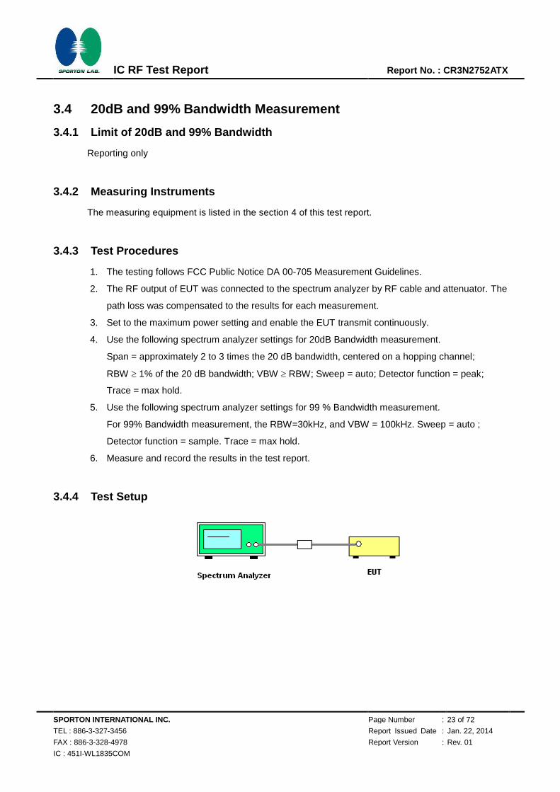
3.4 20dB and 99% Bandwidth Measurement
3.4.1 Limit of 20dB and 99% Bandwidth
Reporting only
3.4.2 Measuring Instruments
The measuring equipment is listed in the section 4 of this test report.
3.4.3 Test Procedures
1. The testing follows FCC Public Notice DA 00-705 Measurement Guidelines.
2. The RF output of EUT was connected to the spectrum analyzer by RF cable and attenuator. The
path loss was compensated to the results for each measurement.
3. Set to the maximum power setting and enable the EUT transmit continuously.
4. Use the following spectrum analyzer settings for 20dB Bandwidth measurement.
Span = approximately 2 to 3 times the 20 dB bandwidth, centered on a hopping channel;
RBW 1% of the 20 dB bandwidth; VBW RBW; Sweep = auto; Detector function = peak;
Trace = max hold.
5. Use the following spectrum analyzer settings for 99 % Bandwidth measurement.
For 99% Bandwidth measurement, the RBW=30kHz, and VBW = 100kHz. Sweep = auto ;
Detector function = sample. Trace = max hold.
6. Measure and record the results in the test report.
3.4.4 Test Setup
SPORTON INTERNATIONAL INC. Page Number : 24 of 72
TEL : 886-3-327-3456 Report Issued Date : Jan. 22, 2014
FAX : 886-3-328-4978 Report Version : Rev. 01
IC : 451I-WL1835COM
IC RF Test Report Report No. : CR3N2752ATX
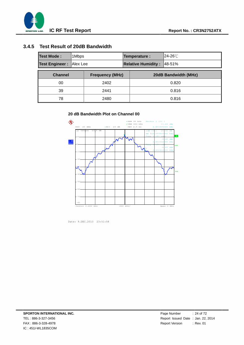
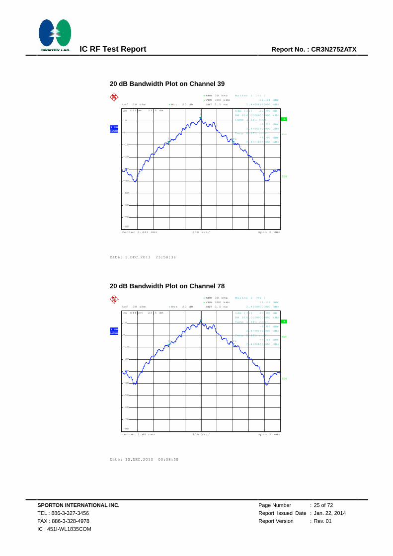
3.4.5 Test Result of 20dB Bandwidth
Test Mode : 1Mbps Temperature : 24-26℃
Test Engineer : Alex Lee Relative Humidity : 48-51%
Channel Frequency (MHz) 20dB Bandwidth (MHz)
00 2402 0.820
39 2441 0.816
78 2480 0.816
20 dB Bandwidth Plot on Channel 00
A
Offset 23.5 dB
LVL
Ref 20 dBm
Center 2.402 GHz Span 2 MHz200 kHz/
Att 20 dB*
3DB
RBW 30 kHz
SWT 2.5 ms
*
VBW 300 kHz*
1 PK
MAXH
-80
-70
-60
-50
-40
-30
-20
-10
0
10
20
1
Marker 1 [T1 ]
11.65 dBm
2.401996000 GHz
ndB [T1] 20.00 dB
BW 820.000000000 kHz
T1
Temp 1 [T1 ndB]
-8.45 dBm
2.401592000 GHz
T2
Temp 2 [T1 ndB]
-8.87 dBm
2.402412000 GHz
Date: 9.DEC.2013 23:51:58
720510
SPORTON INTERNATIONAL INC. Page Number : 25 of 72
TEL : 886-3-327-3456 Report Issued Date : Jan. 22, 2014
FAX : 886-3-328-4978 Report Version : Rev. 01
IC : 451I-WL1835COM
IC RF Test Report Report No. : CR3N2752ATX
20 dB Bandwidth Plot on Channel 39
20 dB Bandwidth Plot on Channel 78
A
Offset 23.5 dB
LVL
Ref 20 dBm
Center 2.441 GHz Span 2 MHz200 kHz/
Att 20 dB*
3DB
RBW 30 kHz
SWT 2.5 ms
*
VBW 300 kHz*
1 PK
MAXH
-80
-70
-60
-50
-40
-30
-20
-10
0
10
20
1
Marker 1 [T1 ]
11.34 dBm
2.440996000 GHz
ndB [T1] 20.00 dB
BW 816.000000000 kHz
T1
Temp 1 [T1 ndB]
-8.26 dBm
2.440592000 GHz
T2
Temp 2 [T1 ndB]
-8.40 dBm
2.441408000 GHz
Date: 9.DEC.2013 23:58:36
A
Offset 23.5 dB
LVL
Ref 20 dBm
Center 2.48 GHz Span 2 MHz200 kHz/
Att 20 dB*
3DB
RBW 30 kHz
SWT 2.5 ms
*
VBW 300 kHz*
1 PK
MAXH
-80
-70
-60
-50
-40
-30
-20
-10
0
10
20
1
Marker 1 [T1 ]
11.23 dBm
2.480000000 GHz
ndB [T1] 20.00 dB
BW 816.000000000 kHz
T1
Temp 1 [T1 ndB]
-8.86 dBm
2.479592000 GHz
T2
Temp 2 [T1 ndB]
-8.47 dBm
2.480408000 GHz
Date: 10.DEC.2013 00:08:50
720510
720510

SPORTON INTERNATIONAL INC. Page Number : 26 of 72
TEL : 886-3-327-3456 Report Issued Date : Jan. 22, 2014
FAX : 886-3-328-4978 Report Version : Rev. 01
IC : 451I-WL1835COM
IC RF Test Report Report No. : CR3N2752ATX
Test Mode : 2Mbps Temperature : 24-26℃
Test Engineer : Alex Lee Relative Humidity : 48-51%
Channel Frequency (MHz) 20dB Bandwidth (MHz)
00 2402 1.278
39 2441 1.278
78 2480 1.278
20 dB Bandwidth Plot on Channel 00
A
Offset 23.5 dB
LVL
Ref 20 dBm
Center 2.402 GHz Span 3 MHz300 kHz/
Att 20 dB*
3DB
RBW 30 kHz
SWT 5 ms
*
VBW 300 kHz*
1 PK
MAXH
-80
-70
-60
-50
-40
-30
-20
-10
0
10
20
1
Marker 1 [T1 ]
7.00 dBm
2.402000000 GHz
ndB [T1] 20.00 dB
BW 1.278000000 MHz
T1
Temp 1 [T1 ndB]
-12.83 dBm
2.401370000 GHz
T2
Temp 2 [T1 ndB]
-13.03 dBm
2.402648000 GHz
Date: 10.DEC.2013 00:18:42
720510
SPORTON INTERNATIONAL INC. Page Number : 27 of 72
TEL : 886-3-327-3456 Report Issued Date : Jan. 22, 2014
FAX : 886-3-328-4978 Report Version : Rev. 01
IC : 451I-WL1835COM
IC RF Test Report Report No. : CR3N2752ATX
20 dB Bandwidth Plot on Channel 39
20 dB Bandwidth Plot on Channel 78
A
Offset 23.5 dB
LVL
Ref 20 dBm
Center 2.441 GHz Span 3 MHz300 kHz/
Att 20 dB*
3DB
RBW 30 kHz
SWT 5 ms
*
VBW 300 kHz*
1 PK
MAXH
-80
-70
-60
-50
-40
-30
-20
-10
0
10
20
1
Marker 1 [T1 ]
6.31 dBm
2.441000000 GHz
ndB [T1] 20.00 dB
BW 1.278000000 MHz
T1
Temp 1 [T1 ndB]
-13.50 dBm
2.440370000 GHz
T2
Temp 2 [T1 ndB]
-13.75 dBm
2.441648000 GHz
Date: 10.DEC.2013 00:29:14
A
Offset 23.5 dB
LVL
Ref 20 dBm
Center 2.48 GHz Span 3 MHz300 kHz/
Att 20 dB*
3DB
RBW 30 kHz
SWT 5 ms
*
VBW 300 kHz*
1 PK
MAXH
-80
-70
-60
-50
-40
-30
-20
-10
0
10
20
1
Marker 1 [T1 ]
5.50 dBm
2.480000000 GHz
ndB [T1] 20.00 dB
BW 1.278000000 MHz
T1
Temp 1 [T1 ndB]
-14.20 dBm
2.479370000 GHz
T2
Temp 2 [T1 ndB]
-14.50 dBm
2.480648000 GHz
Date: 10.DEC.2013 00:31:48
720510
720510
SPORTON INTERNATIONAL INC. Page Number : 28 of 72
TEL : 886-3-327-3456 Report Issued Date : Jan. 22, 2014
FAX : 886-3-328-4978 Report Version : Rev. 01
IC : 451I-WL1835COM
IC RF Test Report Report No. : CR3N2752ATX
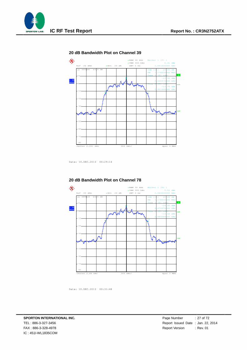
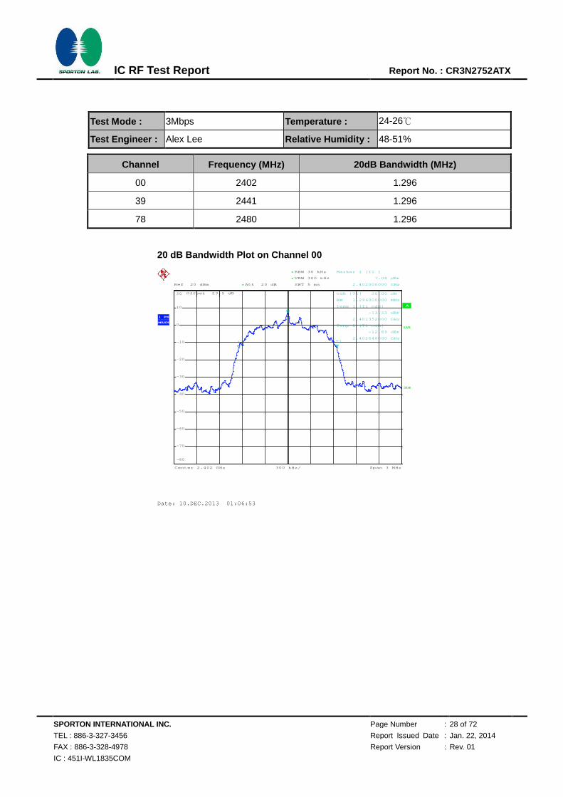
Test Mode : 3Mbps Temperature : 24-26℃
Test Engineer : Alex Lee Relative Humidity : 48-51%
Channel Frequency (MHz) 20dB Bandwidth (MHz)
00 2402 1.296
39 2441 1.296
78 2480 1.296
20 dB Bandwidth Plot on Channel 00
A
Offset 23.5 dB
LVL
Ref 20 dBm
Center 2.402 GHz Span 3 MHz300 kHz/
Att 20 dB*
3DB
RBW 30 kHz
SWT 5 ms
*
VBW 300 kHz*
1 PK
MAXH
-80
-70
-60
-50
-40
-30
-20
-10
0
10
20
1
Marker 1 [T1 ]
7.08 dBm
2.402000000 GHz
ndB [T1] 20.00 dB
BW 1.296000000 MHz
T1
Temp 1 [T1 ndB]
-13.23 dBm
2.401352000 GHz
T2
Temp 2 [T1 ndB]
-12.89 dBm
2.402648000 GHz
Date: 10.DEC.2013 01:06:53
720510

SPORTON INTERNATIONAL INC. Page Number : 29 of 72
TEL : 886-3-327-3456 Report Issued Date : Jan. 22, 2014
FAX : 886-3-328-4978 Report Version : Rev. 01
IC : 451I-WL1835COM
IC RF Test Report Report No. : CR3N2752ATX
20 dB Bandwidth Plot on Channel 39
20 dB Bandwidth Plot on Channel 78
A
Offset 23.5 dB
LVL
Ref 20 dBm
Center 2.441 GHz Span 3 MHz300 kHz/
Att 20 dB*
3DB
RBW 30 kHz
SWT 5 ms
*
VBW 300 kHz*
1 PK
MAXH
-80
-70
-60
-50
-40
-30
-20
-10
0
10
20
1
Marker 1 [T1 ]
6.32 dBm
2.441000000 GHz
ndB [T1] 20.00 dB
BW 1.296000000 MHz
T1
Temp 1 [T1 ndB]
-13.76 dBm
2.440352000 GHz
T2
Temp 2 [T1 ndB]
-13.71 dBm
2.441648000 GHz
Date: 10.DEC.2013 01:03:51
A
Offset 23.5 dB
LVL
Ref 20 dBm
Center 2.48 GHz Span 3 MHz300 kHz/
Att 20 dB*
3DB
RBW 30 kHz
SWT 5 ms
*
VBW 300 kHz*
1 PK
MAXH
-80
-70
-60
-50
-40
-30
-20
-10
0
10
20
1
Marker 1 [T1 ]
5.44 dBm
2.480000000 GHz
ndB [T1] 20.00 dB
BW 1.296000000 MHz
T1
Temp 1 [T1 ndB]
-14.68 dBm
2.479352000 GHz
T2
Temp 2 [T1 ndB]
-14.53 dBm
2.480648000 GHz
Date: 10.DEC.2013 00:54:04
720510
720510
SPORTON INTERNATIONAL INC. Page Number : 30 of 72
TEL : 886-3-327-3456 Report Issued Date : Jan. 22, 2014
FAX : 886-3-328-4978 Report Version : Rev. 01
IC : 451I-WL1835COM
IC RF Test Report Report No. : CR3N2752ATX
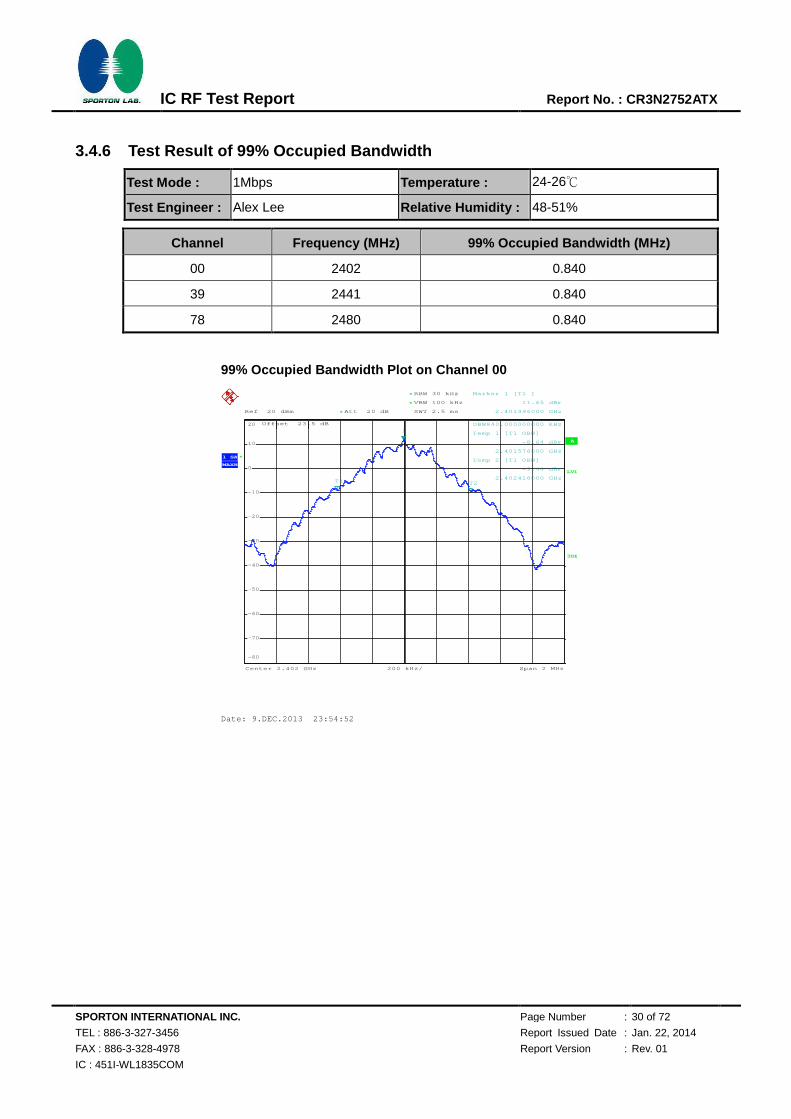
3.4.6 Test Result of 99% Occupied Bandwidth
Test Mode : 1Mbps Temperature : 24-26℃
Test Engineer : Alex Lee Relative Humidity : 48-51%
Channel Frequency (MHz) 99% Occupied Bandwidth (MHz)
00 2402 0.840
39 2441 0.840
78 2480 0.840
99% Occupied Bandwidth Plot on Channel 00
A
Offset 23.5 dB
LVL
Ref 20 dBm
Center 2.402 GHz Span 2 MHz200 kHz/
Att 20 dB*
*
*
3DB
RBW 30 kHz
VBW 100 kHz
SWT 2.5 ms
*
1 SA
MAXH
-80
-70
-60
-50
-40
-30
-20
-10
0
10
20
1
Marker 1 [T1 ]
11.65 dBm
2.401996000 GHz
OBW840.000000000 kHz
T1
Temp 1 [T1 OBW]
-8.64 dBm
2.401576000 GHz
T2
Temp 2 [T1 OBW]
-9.44 dBm
2.402416000 GHz
Date: 9.DEC.2013 23:54:52
720510

SPORTON INTERNATIONAL INC. Page Number : 31 of 72
TEL : 886-3-327-3456 Report Issued Date : Jan. 22, 2014
FAX : 886-3-328-4978 Report Version : Rev. 01
IC : 451I-WL1835COM
IC RF Test Report Report No. : CR3N2752ATX
99% Occupied Bandwidth Plot on Channel 39
99% Occupied Bandwidth Plot on Channel 78
A
Offset 23.5 dB
LVL
Ref 20 dBm
Center 2.441 GHz Span 2 MHz200 kHz/
Att 20 dB*
*
*
3DB
RBW 30 kHz
VBW 100 kHz
SWT 2.5 ms
*
1 SA
MAXH
-80
-70
-60
-50
-40
-30
-20
-10
0
10
20
1
Marker 1 [T1 ]
11.40 dBm
2.440996000 GHz
OBW840.000000000 kHz
T1
Temp 1 [T1 OBW]
-8.81 dBm
2.440576000 GHz
T2
Temp 2 [T1 OBW]
-9.43 dBm
2.441416000 GHz
Date: 10.DEC.2013 00:00:20
A
Offset 23.5 dB
LVL
Ref 20 dBm
Center 2.48 GHz Span 2 MHz200 kHz/
Att 20 dB*
*
*
3DB
RBW 30 kHz
VBW 100 kHz
SWT 2.5 ms
*
1 SA
MAXH
-80
-70
-60
-50
-40
-30
-20
-10
0
10
20
1
Marker 1 [T1 ]
11.23 dBm
2.479996000 GHz
OBW840.000000000 kHz
T1
Temp 1 [T1 OBW]
-9.09 dBm
2.479576000 GHz
T2
Temp 2 [T1 OBW]
-9.61 dBm
2.480416000 GHz
Date: 10.DEC.2013 00:13:15
720510
720510
SPORTON INTERNATIONAL INC. Page Number : 32 of 72
TEL : 886-3-327-3456 Report Issued Date : Jan. 22, 2014
FAX : 886-3-328-4978 Report Version : Rev. 01
IC : 451I-WL1835COM
IC RF Test Report Report No. : CR3N2752ATX
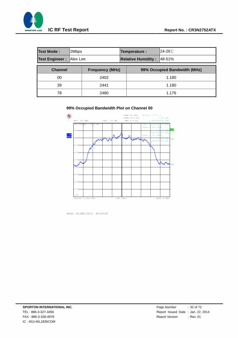
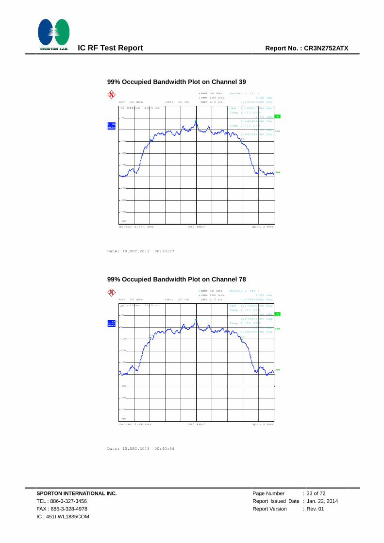
Test Mode : 2Mbps Temperature : 24-26℃
Test Engineer : Alex Lee Relative Humidity : 48-51%
Channel Frequency (MHz) 99% Occupied Bandwidth (MHz)
00 2402 1.180
39 2441 1.180
78 2480 1.176
99% Occupied Bandwidth Plot on Channel 00
A
Offset 23.5 dB
LVL
Ref 20 dBm
Center 2.402 GHz Span 2 MHz200 kHz/
Att 20 dB*
*
*
3DB
RBW 30 kHz
VBW 100 kHz
SWT 2.5 ms
*
1 SA
MAXH
-80
-70
-60
-50
-40
-30
-20
-10
0
10
20
1
Marker 1 [T1 ]
7.00 dBm
2.402000000 GHz
OBW 1.180000000 MHz
T1
Temp 1 [T1 OBW]
-8.79 dBm
2.401404000 GHz
T2
Temp 2 [T1 OBW]
-10.42 dBm
2.402584000 GHz
Date: 10.DEC.2013 00:20:52
720510
SPORTON INTERNATIONAL INC. Page Number : 33 of 72
TEL : 886-3-327-3456 Report Issued Date : Jan. 22, 2014
FAX : 886-3-328-4978 Report Version : Rev. 01
IC : 451I-WL1835COM
IC RF Test Report Report No. : CR3N2752ATX
99% Occupied Bandwidth Plot on Channel 39
99% Occupied Bandwidth Plot on Channel 78
A
Offset 23.5 dB
LVL
Ref 20 dBm
Center 2.441 GHz Span 2 MHz200 kHz/
Att 20 dB*
*
*
3DB
RBW 30 kHz
VBW 100 kHz
SWT 2.5 ms
*
1 SA
MAXH
-80
-70
-60
-50
-40
-30
-20
-10
0
10
20
1
Marker 1 [T1 ]
6.28 dBm
2.440992000 GHz
OBW 1.180000000 MHz
T1
Temp 1 [T1 OBW]
-9.59 dBm
2.440404000 GHz
T2
Temp 2 [T1 OBW]
-11.39 dBm
2.441584000 GHz
Date: 10.DEC.2013 00:30:07
A
Offset 23.5 dB
LVL
Ref 20 dBm
Center 2.48 GHz Span 2 MHz200 kHz/
Att 20 dB*
*
*
3DB
RBW 30 kHz
VBW 100 kHz
SWT 2.5 ms
*
1 SA
MAXH
-80
-70
-60
-50
-40
-30
-20
-10
0
10
20
1
Marker 1 [T1 ]
5.57 dBm
2.479996000 GHz
OBW 1.176000000 MHz
T1
Temp 1 [T1 OBW]
-10.02 dBm
2.479408000 GHz
T2
Temp 2 [T1 OBW]
-11.75 dBm
2.480584000 GHz
Date: 10.DEC.2013 00:40:34
720510
720510

SPORTON INTERNATIONAL INC. Page Number : 34 of 72
TEL : 886-3-327-3456 Report Issued Date : Jan. 22, 2014
FAX : 886-3-328-4978 Report Version : Rev. 01
IC : 451I-WL1835COM
IC RF Test Report Report No. : CR3N2752ATX
Test Mode : 3Mbps Temperature : 24-26℃
Test Engineer : Alex Lee Relative Humidity : 48-51%
Channel Frequency (MHz) 99% Occupied Bandwidth (MHz)
00 2402 1.188
39 2441 1.184
78 2480 1.180
99% Occupied Bandwidth Plot on Channel 00
A
Offset 23.5 dB
LVL
Ref 20 dBm
Center 2.402 GHz Span 2 MHz200 kHz/
Att 20 dB*
*
*
3DB
RBW 30 kHz
VBW 100 kHz
SWT 2.5 ms
*
1 SA
MAXH
-80
-70
-60
-50
-40
-30
-20
-10
0
10
20
1
Marker 1 [T1 ]
6.92 dBm
2.401992000 GHz
OBW 1.188000000 MHz
T1
Temp 1 [T1 OBW]
-11.44 dBm
2.401404000 GHz
T2
Temp 2 [T1 OBW]
-8.90 dBm
2.402592000 GHz
Date: 10.DEC.2013 01:07:35
720510

SPORTON INTERNATIONAL INC. Page Number : 35 of 72
TEL : 886-3-327-3456 Report Issued Date : Jan. 22, 2014
FAX : 886-3-328-4978 Report Version : Rev. 01
IC : 451I-WL1835COM
IC RF Test Report Report No. : CR3N2752ATX
99% Occupied Bandwidth Plot on Channel 39
99% Occupied Bandwidth Plot on Channel 78
A
Offset 23.5 dB
LVL
Ref 20 dBm
Center 2.441 GHz Span 2 MHz200 kHz/
Att 20 dB*
*
*
3DB
RBW 30 kHz
VBW 100 kHz
SWT 2.5 ms
*
1 SA
MAXH
-80
-70
-60
-50
-40
-30
-20
-10
0
10
20
1
Marker 1 [T1 ]
6.30 dBm
2.440992000 GHz
OBW 1.184000000 MHz
T1
Temp 1 [T1 OBW]
-12.03 dBm
2.440404000 GHz
T2
Temp 2 [T1 OBW]
-9.67 dBm
2.441588000 GHz
Date: 10.DEC.2013 01:04:29
A
Offset 23.5 dB
LVL
Ref 20 dBm
Center 2.48 GHz Span 2 MHz200 kHz/
Att 20 dB*
*
*
3DB
RBW 30 kHz
VBW 100 kHz
SWT 2.5 ms
*
1 SA
MAXH
-80
-70
-60
-50
-40
-30
-20
-10
0
10
20
1
Marker 1 [T1 ]
5.46 dBm
2.480000000 GHz
OBW 1.180000000 MHz
T1
Temp 1 [T1 OBW]
-12.08 dBm
2.479408000 GHz
T2
Temp 2 [T1 OBW]
-10.54 dBm
2.480588000 GHz
Date: 10.DEC.2013 01:00:08
720510
720510
SPORTON INTERNATIONAL INC. Page Number : 36 of 72
TEL : 886-3-327-3456 Report Issued Date : Jan. 22, 2014
FAX : 886-3-328-4978 Report Version : Rev. 01
IC : 451I-WL1835COM
IC RF Test Report Report No. : CR3N2752ATX
3.5 Peak Output Power Measurement
3.5.1 Limit of Peak Output Power
Section 15.247 (b) The maximum peak conducted output power of the intentional radiator shall not
exceed the following: (1) For frequency hopping systems operating in the 2400-2483.5 MHz band
employing at least 75 non-overlapping hopping channels, and all frequency hopping systems in the
5725-5850 MHz band: 1 watt. For all other frequency hopping systems in the 2400-2483.5 MHz band
0.125 watts. The power limit for 1Mbps is 1watt, and for 2Mbps, 3Mbps and AFH are 0.125 watts.
3.5.2 Measuring Instruments
The measuring equipment is listed in the section 4 of this test report.
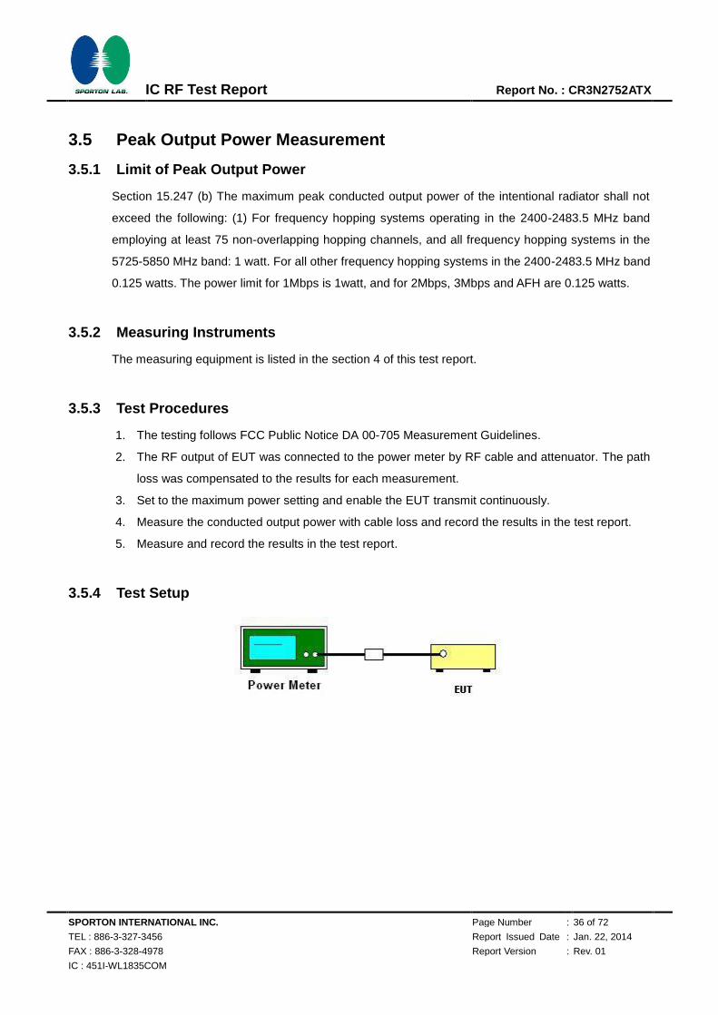
3.5.3 Test Procedures
1. The testing follows FCC Public Notice DA 00-705 Measurement Guidelines.
2. The RF output of EUT was connected to the power meter by RF cable and attenuator. The path
loss was compensated to the results for each measurement.
3. Set to the maximum power setting and enable the EUT transmit continuously.
4. Measure the conducted output power with cable loss and record the results in the test report.
5. Measure and record the results in the test report.
3.5.4 Test Setup
SPORTON INTERNATIONAL INC. Page Number : 37 of 72
TEL : 886-3-327-3456 Report Issued Date : Jan. 22, 2014
FAX : 886-3-328-4978 Report Version : Rev. 01
IC : 451I-WL1835COM
IC RF Test Report Report No. : CR3N2752ATX
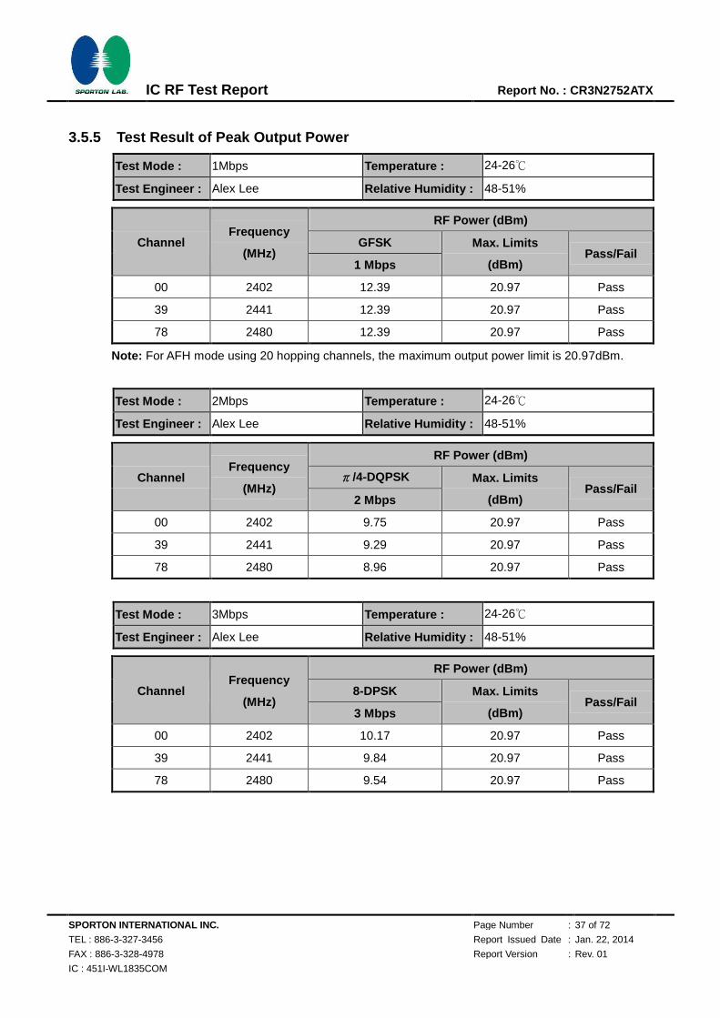
3.5.5 Test Result of Peak Output Power
Test Mode : 1Mbps Temperature : 24-26℃
Test Engineer : Alex Lee Relative Humidity : 48-51%
Channel Frequency
(MHz)
RF Power (dBm)
GFSK Max. Limits
(dBm) Pass/Fail
1 Mbps
00 2402 12.39 20.97 Pass
39 2441 12.39 20.97 Pass
78 2480 12.39 20.97 Pass
Note: For AFH mode using 20 hopping channels, the maximum output power limit is 20.97dBm.
Test Mode : 2Mbps Temperature : 24-26℃
Test Engineer : Alex Lee Relative Humidity : 48-51%
Channel Frequency
(MHz)
RF Power (dBm)
π/4-DQPSK Max. Limits
(dBm) Pass/Fail
2 Mbps
00 2402 9.75 20.97 Pass
39 2441 9.29 20.97 Pass
78 2480 8.96 20.97 Pass
Test Mode : 3Mbps Temperature : 24-26℃
Test Engineer : Alex Lee Relative Humidity : 48-51%
Channel Frequency
(MHz)
RF Power (dBm)
8-DPSK Max. Limits
(dBm) Pass/Fail
3 Mbps
00 2402 10.17 20.97 Pass
39 2441 9.84 20.97 Pass
78 2480 9.54 20.97 Pass

SPORTON INTERNATIONAL INC. Page Number : 38 of 72
TEL : 886-3-327-3456 Report Issued Date : Jan. 22, 2014
FAX : 886-3-328-4978 Report Version : Rev. 01
IC : 451I-WL1835COM
IC RF Test Report Report No. : CR3N2752ATX
3.6 Conducted Band Edges Measurement
3.6.1 Limit of Band Edges
In any 100 kHz bandwidth outside the intentional radiation frequency band, the radio frequency power
shall be at least 20 dB below the highest level of the radiated power. In addition, radiated emissions
which fall in the restricted bands must also comply with the radiated emission limits.
3.6.2 Measuring Instruments
The measuring equipment is listed in the section 4 of this test report.
3.6.3 Test Procedures
1. The testing follows the guidelines in Band-edge Compliance of RF Conducted Emissions of
FCC Public Notice DA 00-705 Measurement Guidelines.
2. Set to the maximum power setting and enable the EUT transmit continuously.
3. Set RBW = 100kHz ( 1% span=10MHz ), VBW = 300kHz ( RBW). Band edge emissions
must be at least 20 dB down from the highest emission level within the authorized band as
measured with a 100kHz RBW. The attenuation shall be 30 dB instead of 20 dB when RMS
conducted output power procedure is used.
4. Enable hopping function of the EUT and then repeat step 2. and 3.
5. Measure and record the results in the test report.
3.6.4 Test Setup
SPORTON INTERNATIONAL INC. Page Number : 39 of 72
TEL : 886-3-327-3456 Report Issued Date : Jan. 22, 2014
FAX : 886-3-328-4978 Report Version : Rev. 01
IC : 451I-WL1835COM
IC RF Test Report Report No. : CR3N2752ATX
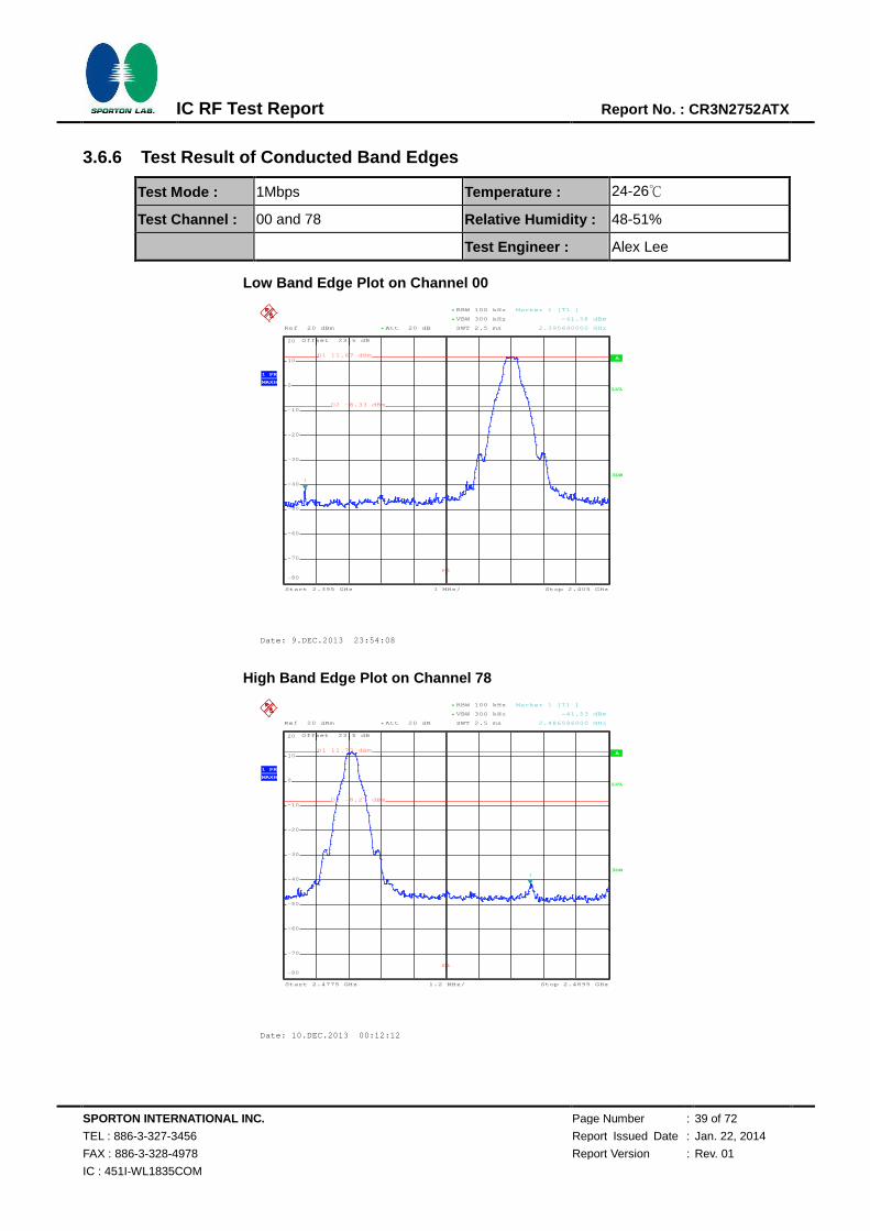
3.6.6 Test Result of Conducted Band Edges
Test Mode : 1Mbps Temperature : 24-26℃
Test Channel : 00 and 78 Relative Humidity : 48-51%
Test Engineer : Alex Lee
Low Band Edge Plot on Channel 00
High Band Edge Plot on Channel 78
A
Offset 23.5 dB
LVL
Ref 20 dBm Att 20 dB*
1 MHz/Start 2.395 GHz Stop 2.405 GHz
3DB
RBW 100 kHz
SWT 2.5 ms
*
VBW 300 kHz*
1 PK
MAXH
-80
-70
-60
-50
-40
-30
-20
-10
0
10
20
1
Marker 1 [T1 ]
-41.58 dBm
2.395640000 GHz
D1 11.67 dBm
D2 -8.33 dBm
F1
Date: 9.DEC.2013 23:54:08
A
Offset 23.5 dB
LVL
Ref 20 dBm Att 20 dB*
1.2 MHz/Start 2.4775 GHz Stop 2.4895 GHz
3DB
RBW 100 kHz
SWT 2.5 ms
*
VBW 300 kHz*
1 PK
MAXH
-80
-70
-60
-50
-40
-30
-20
-10
0
10
20
1
Marker 1 [T1 ]
-41.53 dBm
2.486596000 GHz
D1 11.73 dBm
D2 -8.27 dBm
F1
Date: 10.DEC.2013 00:12:12
720510
720510
SPORTON INTERNATIONAL INC. Page Number : 40 of 72
TEL : 886-3-327-3456 Report Issued Date : Jan. 22, 2014
FAX : 886-3-328-4978 Report Version : Rev. 01
IC : 451I-WL1835COM
IC RF Test Report Report No. : CR3N2752ATX
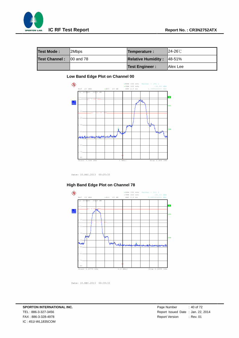
Test Mode : 2Mbps Temperature : 24-26℃
Test Channel : 00 and 78 Relative Humidity : 48-51%
Test Engineer : Alex Lee
Low Band Edge Plot on Channel 00
High Band Edge Plot on Channel 78
A
Offset 23.5 dB
LVL
Ref 20 dBm Att 20 dB*
1 MHz/Start 2.395 GHz Stop 2.405 GHz
3DB
RBW 100 kHz
SWT 2.5 ms
*
VBW 300 kHz*
1 PK
MAXH
-80
-70
-60
-50
-40
-30
-20
-10
0
10
20
1
Marker 1 [T1 ]
-36.86 dBm
2.399520000 GHz
D1 7.65 dBm
D2 -12.35 dBm
F1
Date: 10.DEC.2013 00:25:33
A
Offset 23.5 dB
LVL
Ref 20 dBm Att 20 dB*
1.2 MHz/Start 2.4775 GHz Stop 2.4895 GHz
3DB
RBW 100 kHz
SWT 2.5 ms
*
VBW 300 kHz*
1 PK
MAXH
-80
-70
-60
-50
-40
-30
-20
-10
0
10
20
1
Marker 1 [T1 ]
-45.10 dBm
2.485324000 GHz
D1 6.08 dBm
D2 -13.92 dBm
F1
Date: 10.DEC.2013 00:39:33
720510

SPORTON INTERNATIONAL INC. Page Number : 41 of 72
TEL : 886-3-327-3456 Report Issued Date : Jan. 22, 2014
FAX : 886-3-328-4978 Report Version : Rev. 01
IC : 451I-WL1835COM
IC RF Test Report Report No. : CR3N2752ATX
Test Mode : 3Mbps Temperature : 24-26℃
Test Channel : 00 and 78 Relative Humidity : 48-51%
Test Engineer : Alex Lee
Low Band Edge Plot on Channel 00
High Band Edge Plot on Channel 78
A
Offset 23.5 dB
LVL
Ref 20 dBm Att 20 dB*
1 MHz/Start 2.395 GHz Stop 2.405 GHz
3DB
RBW 100 kHz
SWT 2.5 ms
*
VBW 300 kHz*
1 PK
MAXH
-80
-70
-60
-50
-40
-30
-20
-10
0
10
20
1
Marker 1 [T1 ]
-36.41 dBm
2.399540000 GHz
D1 7.64 dBm
D2 -12.36 dBm
F1
Date: 10.DEC.2013 01:14:41
A
Offset 23.5 dB
LVL
Ref 20 dBm Att 20 dB*
1.2 MHz/Start 2.4775 GHz Stop 2.4895 GHz
3DB
RBW 100 kHz
SWT 2.5 ms
*
VBW 300 kHz*
1 PK
MAXH
-80
-70
-60
-50
-40
-30
-20
-10
0
10
20
1
Marker 1 [T1 ]
-43.94 dBm
2.486692000 GHz
D1 6.04 dBm
D2 -13.96 dBm
F1
Date: 10.DEC.2013 00:59:19
720510
720510
SPORTON INTERNATIONAL INC. Page Number : 42 of 72
TEL : 886-3-327-3456 Report Issued Date : Jan. 22, 2014
FAX : 886-3-328-4978 Report Version : Rev. 01
IC : 451I-WL1835COM
IC RF Test Report Report No. : CR3N2752ATX
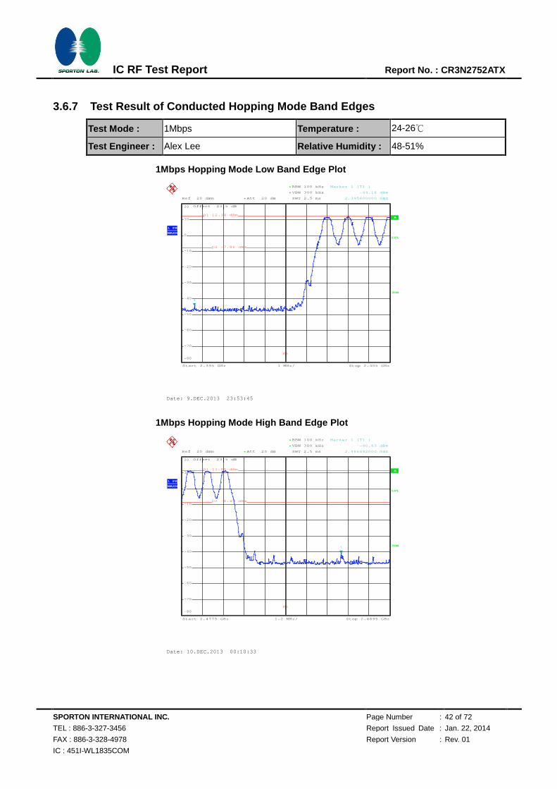
3.6.7 Test Result of Conducted Hopping Mode Band Edges
Test Mode : 1Mbps Temperature : 24-26℃
Test Engineer : Alex Lee Relative Humidity : 48-51%
1Mbps Hopping Mode Low Band Edge Plot
1Mbps Hopping Mode High Band Edge Plot
A
Offset 23.5 dB
LVL
Ref 20 dBm Att 20 dB*
1 MHz/Start 2.395 GHz Stop 2.405 GHz
3DB
RBW 100 kHz
SWT 2.5 ms
*
VBW 300 kHz*
1 PK
MAXH
-80
-70
-60
-50
-40
-30
-20
-10
0
10
20
1
Marker 1 [T1 ]
-44.16 dBm
2.395600000 GHz
D1 12.14 dBm
D2 -7.86 dBm
F1
Date: 9.DEC.2013 23:53:45
A
Offset 23.5 dB
LVL
Ref 20 dBm Att 20 dB*
1.2 MHz/Start 2.4775 GHz Stop 2.4895 GHz
3DB
RBW 100 kHz
SWT 2.5 ms
*
VBW 300 kHz*
1 PK
MAXH
-80
-70
-60
-50
-40
-30
-20
-10
0
10
20
1
Marker 1 [T1 ]
-40.63 dBm
2.486692000 GHz
D1 11.55 dBm
D2 -8.45 dBm
F1
Date: 10.DEC.2013 00:10:33
720510
720510
SPORTON INTERNATIONAL INC. Page Number : 43 of 72
TEL : 886-3-327-3456 Report Issued Date : Jan. 22, 2014
FAX : 886-3-328-4978 Report Version : Rev. 01
IC : 451I-WL1835COM
IC RF Test Report Report No. : CR3N2752ATX
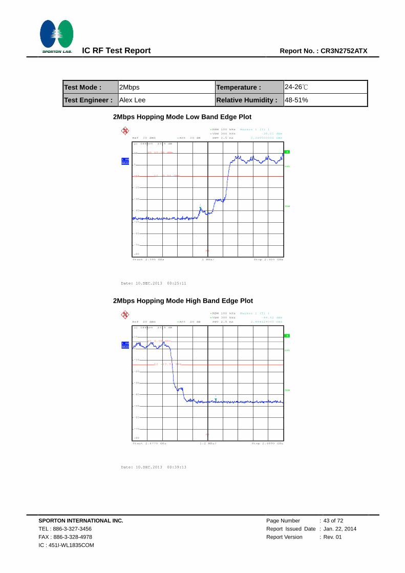
Test Mode : 2Mbps Temperature : 24-26℃
Test Engineer : Alex Lee Relative Humidity : 48-51%
2Mbps Hopping Mode Low Band Edge Plot
2Mbps Hopping Mode High Band Edge Plot
A
Offset 23.5 dB
LVL
Ref 20 dBm Att 20 dB*
1 MHz/Start 2.395 GHz Stop 2.405 GHz
3DB
RBW 100 kHz
SWT 2.5 ms
*
VBW 300 kHz*
1 PK
MAXH
-80
-70
-60
-50
-40
-30
-20
-10
0
10
20
1
Marker 1 [T1 ]
-38.01 dBm
2.399500000 GHz
D1 10.06 dBm
D2 -9.94 dBm
F1
Date: 10.DEC.2013 00:25:11
A
Offset 23.5 dB
LVL
Ref 20 dBm Att 20 dB*
1.2 MHz/Start 2.4775 GHz Stop 2.4895 GHz
3DB
RBW 100 kHz
SWT 2.5 ms
*
VBW 300 kHz*
1 PK
MAXH
-80
-70
-60
-50
-40
-30
-20
-10
0
10
20
1
Marker 1 [T1 ]
-44.62 dBm
2.484124000 GHz
D1 6.08 dBm
D2 -13.92 dBm
F1
Date: 10.DEC.2013 00:39:13
720510
720510
SPORTON INTERNATIONAL INC. Page Number : 44 of 72
TEL : 886-3-327-3456 Report Issued Date : Jan. 22, 2014
FAX : 886-3-328-4978 Report Version : Rev. 01
IC : 451I-WL1835COM
IC RF Test Report Report No. : CR3N2752ATX
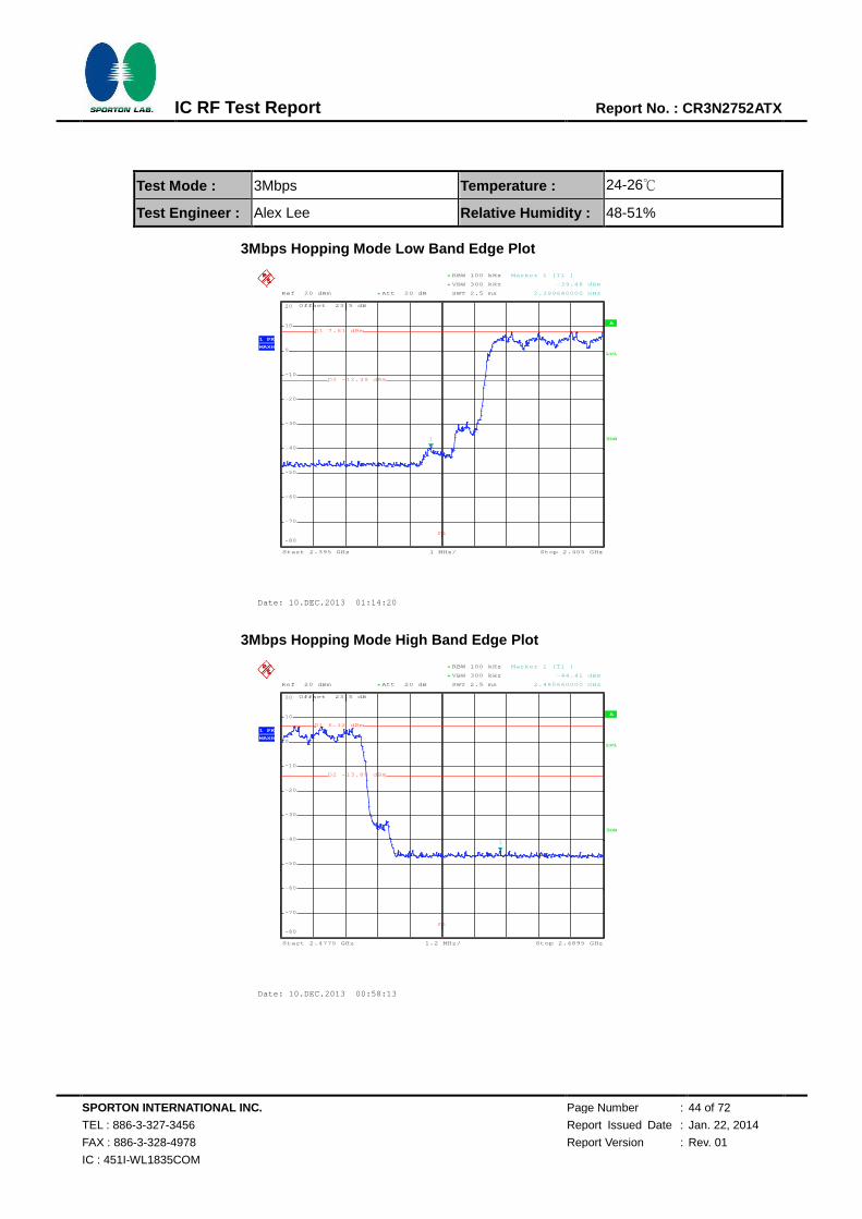
Test Mode : 3Mbps Temperature : 24-26℃
Test Engineer : Alex Lee Relative Humidity : 48-51%
3Mbps Hopping Mode Low Band Edge Plot
3Mbps Hopping Mode High Band Edge Plot
A
Offset 23.5 dB
LVL
Ref 20 dBm Att 20 dB*
1 MHz/Start 2.395 GHz Stop 2.405 GHz
3DB
RBW 100 kHz
SWT 2.5 ms
*
VBW 300 kHz*
1 PK
MAXH
-80
-70
-60
-50
-40
-30
-20
-10
0
10
20
1
Marker 1 [T1 ]
-39.48 dBm
2.399640000 GHz
D1 7.61 dBm
D2 -12.39 dBm
F1
Date: 10.DEC.2013 01:14:20
A
Offset 23.5 dB
LVL
Ref 20 dBm Att 20 dB*
1.2 MHz/Start 2.4775 GHz Stop 2.4895 GHz
3DB
RBW 100 kHz
SWT 2.5 ms
*
VBW 300 kHz*
1 PK
MAXH
-80
-70
-60
-50
-40
-30
-20
-10
0
10
20
1
Marker 1 [T1 ]
-44.41 dBm
2.485660000 GHz
D1 6.12 dBm
D2 -13.88 dBm
F1
Date: 10.DEC.2013 00:58:13
720510
SPORTON INTERNATIONAL INC. Page Number : 45 of 72
TEL : 886-3-327-3456 Report Issued Date : Jan. 22, 2014
FAX : 886-3-328-4978 Report Version : Rev. 01
IC : 451I-WL1835COM
IC RF Test Report Report No. : CR3N2752ATX
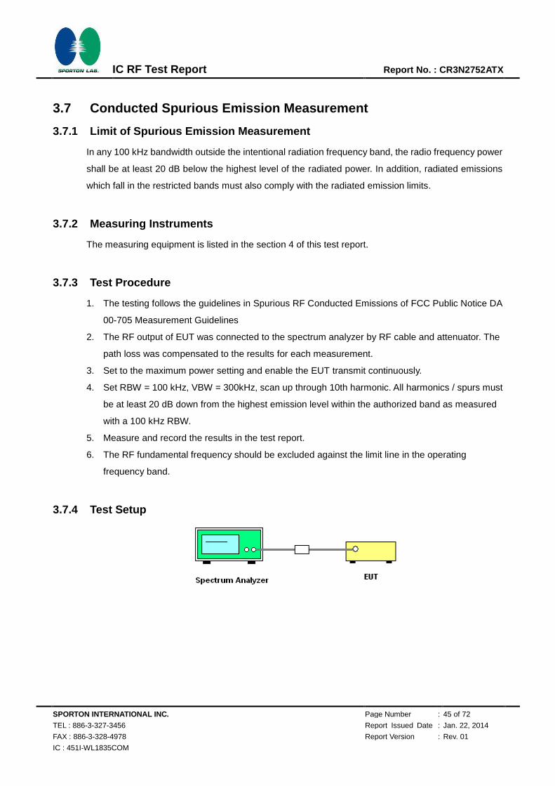
3.7 Conducted Spurious Emission Measurement
3.7.1 Limit of Spurious Emission Measurement
In any 100 kHz bandwidth outside the intentional radiation frequency band, the radio frequency power
shall be at least 20 dB below the highest level of the radiated power. In addition, radiated emissions
which fall in the restricted bands must also comply with the radiated emission limits.
3.7.2 Measuring Instruments
The measuring equipment is listed in the section 4 of this test report.
3.7.3 Test Procedure
1. The testing follows the guidelines in Spurious RF Conducted Emissions of FCC Public Notice DA
00-705 Measurement Guidelines
2. The RF output of EUT was connected to the spectrum analyzer by RF cable and attenuator. The
path loss was compensated to the results for each measurement.
3. Set to the maximum power setting and enable the EUT transmit continuously.
4. Set RBW = 100 kHz, VBW = 300kHz, scan up through 10th harmonic. All harmonics / spurs must
be at least 20 dB down from the highest emission level within the authorized band as measured
with a 100 kHz RBW.
5. Measure and record the results in the test report.
6. The RF fundamental frequency should be excluded against the limit line in the operating
frequency band.
3.7.4 Test Setup

SPORTON INTERNATIONAL INC. Page Number : 46 of 72
TEL : 886-3-327-3456 Report Issued Date : Jan. 22, 2014
FAX : 886-3-328-4978 Report Version : Rev. 01
IC : 451I-WL1835COM
IC RF Test Report Report No. : CR3N2752ATX
3.7.5 Test Result of Conducted Spurious Emission
Test Mode : 1Mbps Temperature : 24-26℃
Test Channel : 00 Relative Humidity : 48-51%
Test Engineer : Alex Lee
1Mbps CSE Plot on Ch 00 between 30MHz ~ 3 GHz
1Mbps CSE Plot on Ch 00 between 2 GHz ~ 25 GHz
A
Att 20 dB*Ref 20 dBm
Offset 23.5 dB
LVL
297 MHz/Start 30 MHz Stop 3 GHz
*
*
3DB
RBW 100 kHz
VBW 300 kHz
SWT 300 ms
1 PK
VIEW
-80
-70
-60
-50
-40
-30
-20
-10
0
10
20
1
Marker 1 [T1 ]
-45.09 dBm
2.506980000 GHz
D1 12.25 dBm
D2 -7.75 dBm
Date: 9.DEC.2013 23:55:20
A
Att 20 dB*Ref 20 dBm
Offset 23.5 dB
LVL
2.3 GHz/Start 2 GHz Stop 25 GHz
*
*
RBW 100 kHz
VBW 300 kHz
SWT 2.3 s
3DB
1 PK
VIEW
-80
-70
-60
-50
-40
-30
-20
-10
0
10
20
1
Marker 1 [T1 ]
-29.88 dBm
24.770000000 GHz
D1 12.11 dBm
D2 -7.89 dBm
Date: 9.DEC.2013 23:55:43
720510
720510

SPORTON INTERNATIONAL INC. Page Number : 47 of 72
TEL : 886-3-327-3456 Report Issued Date : Jan. 22, 2014
FAX : 886-3-328-4978 Report Version : Rev. 01
IC : 451I-WL1835COM
IC RF Test Report Report No. : CR3N2752ATX
Test Mode : 1Mbps Temperature : 24-26℃
Test Channel : 39 Relative Humidity : 48-51%
Test Engineer : Alex Lee
1Mbps CSE Plot on Ch 39 between 30MHz ~ 3 GHz
1Mbps CSE Plot on Ch 39 between 2 GHz ~ 25 GHz
A
Att 20 dB*Ref 20 dBm
Offset 23.5 dB
LVL
297 MHz/Start 30 MHz Stop 3 GHz
*
*
3DB
RBW 100 kHz
VBW 300 kHz
SWT 300 ms
1 PK
VIEW
-80
-70
-60
-50
-40
-30
-20
-10
0
10
20
1
Marker 1 [T1 ]
-44.82 dBm
3.000000000 GHz
D1 11.74 dBm
D2 -8.26 dBm
Date: 10.DEC.2013 00:00:52
A
Att 20 dB*Ref 20 dBm
Offset 23.5 dB
LVL
2.3 GHz/Start 2 GHz Stop 25 GHz
*
*
RBW 100 kHz
VBW 300 kHz
SWT 2.3 s
3DB
1 PK
VIEW
-80
-70
-60
-50
-40
-30
-20
-10
0
10
20
1
Marker 1 [T1 ]
-29.45 dBm
25.000000000 GHz
D1 10.56 dBm
D2 -9.44 dBm
Date: 10.DEC.2013 00:01:14
720510
720510
SPORTON INTERNATIONAL INC. Page Number : 48 of 72
TEL : 886-3-327-3456 Report Issued Date : Jan. 22, 2014
FAX : 886-3-328-4978 Report Version : Rev. 01
IC : 451I-WL1835COM
IC RF Test Report Report No. : CR3N2752ATX
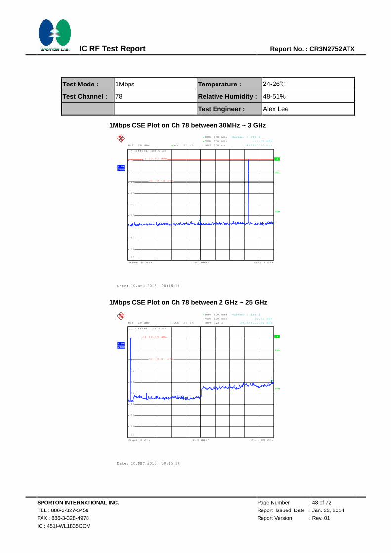
Test Mode : 1Mbps Temperature : 24-26℃
Test Channel : 78 Relative Humidity : 48-51%
Test Engineer : Alex Lee
1Mbps CSE Plot on Ch 78 between 30MHz ~ 3 GHz
1Mbps CSE Plot on Ch 78 between 2 GHz ~ 25 GHz
A
Att 20 dB*Ref 20 dBm
Offset 23.5 dB
LVL
297 MHz/Start 30 MHz Stop 3 GHz
*
*
3DB
RBW 100 kHz
VBW 300 kHz
SWT 300 ms
1 PK
VIEW
-80
-70
-60
-50
-40
-30
-20
-10
0
10
20
1
Marker 1 [T1 ]
-45.16 dBm
1.497180000 GHz
D1 10.82 dBm
D2 -9.18 dBm
Date: 10.DEC.2013 00:15:11
A
Att 20 dB*Ref 20 dBm
Offset 23.5 dB
LVL
2.3 GHz/Start 2 GHz Stop 25 GHz
*
*
RBW 100 kHz
VBW 300 kHz
SWT 2.3 s
3DB
1 PK
VIEW
-80
-70
-60
-50
-40
-30
-20
-10
0
10
20
1
Marker 1 [T1 ]
-29.21 dBm
24.724000000 GHz
D1 10.19 dBm
D2 -9.81 dBm
Date: 10.DEC.2013 00:15:34
720510
720510
SPORTON INTERNATIONAL INC. Page Number : 49 of 72
TEL : 886-3-327-3456 Report Issued Date : Jan. 22, 2014
FAX : 886-3-328-4978 Report Version : Rev. 01
IC : 451I-WL1835COM
IC RF Test Report Report No. : CR3N2752ATX
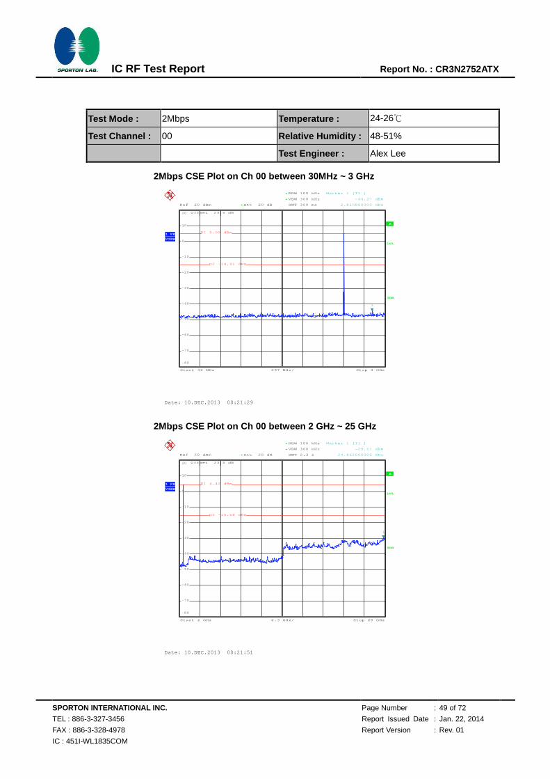
Test Mode : 2Mbps Temperature : 24-26℃
Test Channel : 00 Relative Humidity : 48-51%
Test Engineer : Alex Lee
2Mbps CSE Plot on Ch 00 between 30MHz ~ 3 GHz
2Mbps CSE Plot on Ch 00 between 2 GHz ~ 25 GHz
A
Att 20 dB*Ref 20 dBm
Offset 23.5 dB
LVL
297 MHz/Start 30 MHz Stop 3 GHz
*
*
3DB
RBW 100 kHz
VBW 300 kHz
SWT 300 ms
1 PK
VIEW
-80
-70
-60
-50
-40
-30
-20
-10
0
10
20
1
Marker 1 [T1 ]
-44.27 dBm
2.815860000 GHz
D1 5.09 dBm
D2 -14.91 dBm
Date: 10.DEC.2013 00:21:29
A
Att 20 dB*Ref 20 dBm
Offset 23.5 dB
LVL
2.3 GHz/Start 2 GHz Stop 25 GHz
*
*
RBW 100 kHz
VBW 300 kHz
SWT 2.3 s
3DB
1 PK
VIEW
-80
-70
-60
-50
-40
-30
-20
-10
0
10
20
1
Marker 1 [T1 ]
-29.51 dBm
24.862000000 GHz
D1 4.42 dBm
D2 -15.58 dBm
Date: 10.DEC.2013 00:21:51
720510
720510

SPORTON INTERNATIONAL INC. Page Number : 50 of 72
TEL : 886-3-327-3456 Report Issued Date : Jan. 22, 2014
FAX : 886-3-328-4978 Report Version : Rev. 01
IC : 451I-WL1835COM
IC RF Test Report Report No. : CR3N2752ATX
Test Mode : 2Mbps Temperature : 24-26℃
Test Channel : 39 Relative Humidity : 48-51%
Test Engineer : Alex Lee
2Mbps CSE Plot on Ch 39 between 30MHz ~ 3 GHz
2Mbps CSE Plot on Ch 39 between 2 GHz ~ 25 GHz
A
Att 20 dB*Ref 20 dBm
Offset 23.5 dB
LVL
297 MHz/Start 30 MHz Stop 3 GHz
*
*
3DB
RBW 100 kHz
VBW 300 kHz
SWT 300 ms
1 PK
VIEW
-80
-70
-60
-50
-40
-30
-20
-10
0
10
20
1
Marker 1 [T1 ]
-45.26 dBm
1.425900000 GHz
D1 6.97 dBm
D2 -13.03 dBm
Date: 10.DEC.2013 00:30:55
A
Att 20 dB*Ref 20 dBm
Offset 23.5 dB
LVL
2.3 GHz/Start 2 GHz Stop 25 GHz
*
*
RBW 100 kHz
VBW 300 kHz
SWT 2.3 s
3DB
1 PK
VIEW
-80
-70
-60
-50
-40
-30
-20
-10
0
10
20
1
Marker 1 [T1 ]
-30.05 dBm
24.908000000 GHz
D1 3.49 dBm
D2 -16.51 dBm
Date: 10.DEC.2013 00:31:17
720510
720510

SPORTON INTERNATIONAL INC. Page Number : 51 of 72
TEL : 886-3-327-3456 Report Issued Date : Jan. 22, 2014
FAX : 886-3-328-4978 Report Version : Rev. 01
IC : 451I-WL1835COM
IC RF Test Report Report No. : CR3N2752ATX
Test Mode : 2Mbps Temperature : 24-26℃
Test Channel : 78 Relative Humidity : 48-51%
Test Engineer : Alex Lee
2Mbps CSE Plot on Ch 78 between 30MHz ~ 3 GHz
2Mbps CSE Plot on Ch 78 between 2 GHz ~ 25 GHz
A
Att 20 dB*Ref 20 dBm
Offset 23.5 dB
LVL
297 MHz/Start 30 MHz Stop 3 GHz
*
*
3DB
RBW 100 kHz
VBW 300 kHz
SWT 300 ms
1 PK
VIEW
-80
-70
-60
-50
-40
-30
-20
-10
0
10
20
1
Marker 1 [T1 ]
-45.28 dBm
2.667360000 GHz
D1 4.28 dBm
D2 -15.72 dBm
Date: 10.DEC.2013 00:41:01
A
Att 20 dB*Ref 20 dBm
Offset 23.5 dB
LVL
2.3 GHz/Start 2 GHz Stop 25 GHz
*
*
RBW 100 kHz
VBW 300 kHz
SWT 2.3 s
3DB
1 PK
VIEW
-80
-70
-60
-50
-40
-30
-20
-10
0
10
20
1
Marker 1 [T1 ]
-30.16 dBm
24.954000000 GHz
D1 2.53 dBm
D2 -17.47 dBm
Date: 10.DEC.2013 00:41:24
720510
720510
SPORTON INTERNATIONAL INC. Page Number : 52 of 72
TEL : 886-3-327-3456 Report Issued Date : Jan. 22, 2014
FAX : 886-3-328-4978 Report Version : Rev. 01
IC : 451I-WL1835COM
IC RF Test Report Report No. : CR3N2752ATX
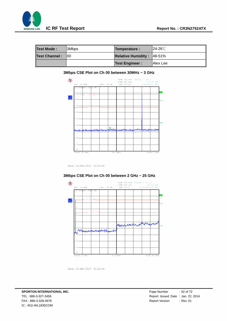
Test Mode : 3Mbps Temperature : 24-26℃
Test Channel : 00 Relative Humidity : 48-51%
Test Engineer : Alex Lee
3Mbps CSE Plot on Ch 00 between 30MHz ~ 3 GHz
3Mbps CSE Plot on Ch 00 between 2 GHz ~ 25 GHz
A
Att 20 dB*Ref 20 dBm
Offset 23.5 dB
LVL
297 MHz/Start 30 MHz Stop 3 GHz
*
*
3DB
RBW 100 kHz
VBW 300 kHz
SWT 300 ms
1 PK
VIEW
-80
-70
-60
-50
-40
-30
-20
-10
0
10
20
1
Marker 1 [T1 ]
-44.66 dBm
1.289280000 GHz
D1 7.66 dBm
D2 -12.34 dBm
Date: 10.DEC.2013 01:21:42
A
Att 20 dB*Ref 20 dBm
Offset 23.5 dB
LVL
2.3 GHz/Start 2 GHz Stop 25 GHz
*
*
RBW 100 kHz
VBW 300 kHz
SWT 2.3 s
3DB
1 PK
VIEW
-80
-70
-60
-50
-40
-30
-20
-10
0
10
20
1
Marker 1 [T1 ]
-29.53 dBm
24.908000000 GHz
D1 4.22 dBm
D2 -15.78 dBm
Date: 10.DEC.2013 01:22:04
720510
720510

SPORTON INTERNATIONAL INC. Page Number : 53 of 72
TEL : 886-3-327-3456 Report Issued Date : Jan. 22, 2014
FAX : 886-3-328-4978 Report Version : Rev. 01
IC : 451I-WL1835COM
IC RF Test Report Report No. : CR3N2752ATX
Test Mode : 3Mbps Temperature : 24-26℃
Test Channel : 39 Relative Humidity : 48-51%
Test Engineer : Alex Lee
3Mbps CSE Plot on Ch 39 between 30MHz ~ 3 GHz
3Mbps CSE Plot on Ch 39 between 2 GHz ~ 25 GHz
A
Att 20 dB*Ref 20 dBm
Offset 23.5 dB
LVL
297 MHz/Start 30 MHz Stop 3 GHz
*
*
3DB
RBW 100 kHz
VBW 300 kHz
SWT 300 ms
1 PK
VIEW
-80
-70
-60
-50
-40
-30
-20
-10
0
10
20
1
Marker 1 [T1 ]
-43.08 dBm
2.976240000 GHz
D1 4.31 dBm
D2 -15.69 dBm
Date: 10.DEC.2013 01:04:55
A
Att 20 dB*Ref 20 dBm
Offset 23.5 dB
LVL
2.3 GHz/Start 2 GHz Stop 25 GHz
*
*
RBW 100 kHz
VBW 300 kHz
SWT 2.3 s
3DB
1 PK
VIEW
-80
-70
-60
-50
-40
-30
-20
-10
0
10
20
1
Marker 1 [T1 ]
-28.07 dBm
24.816000000 GHz
D1 2.61 dBm
D2 -17.39 dBm
Date: 10.DEC.2013 01:05:18
720510
720510

SPORTON INTERNATIONAL INC. Page Number : 54 of 72
TEL : 886-3-327-3456 Report Issued Date : Jan. 22, 2014
FAX : 886-3-328-4978 Report Version : Rev. 01
IC : 451I-WL1835COM
IC RF Test Report Report No. : CR3N2752ATX
Test Mode : 3Mbps Temperature : 24-26℃
Test Channel : 78 Relative Humidity : 48-51%
Test Engineer : Alex Lee
3Mbps CSE Plot on Ch 78 between 30MHz ~ 3 GHz
3Mbps CSE Plot on Ch 78 between 2 GHz ~ 25 GHz
A
Att 20 dB*Ref 20 dBm
Offset 23.5 dB
LVL
297 MHz/Start 30 MHz Stop 3 GHz
*
*
3DB
RBW 100 kHz
VBW 300 kHz
SWT 300 ms
1 PK
VIEW
-80
-70
-60
-50
-40
-30
-20
-10
0
10
20
1
Marker 1 [T1 ]
-45.02 dBm
2.982180000 GHz
D1 4.13 dBm
D2 -15.87 dBm
Date: 10.DEC.2013 01:01:38
A
Att 20 dB*Ref 20 dBm
Offset 23.5 dB
LVL
2.3 GHz/Start 2 GHz Stop 25 GHz
*
*
RBW 100 kHz
VBW 300 kHz
SWT 2.3 s
3DB
1 PK
VIEW
-80
-70
-60
-50
-40
-30
-20
-10
0
10
20
1
Marker 1 [T1 ]
-30.17 dBm
20.630000000 GHz
D1 2.74 dBm
D2 -17.26 dBm
Date: 10.DEC.2013 01:02:00
720510
720510
SPORTON INTERNATIONAL INC. Page Number : 55 of 72
TEL : 886-3-327-3456 Report Issued Date : Jan. 22, 2014
FAX : 886-3-328-4978 Report Version : Rev. 01
IC : 451I-WL1835COM
IC RF Test Report Report No. : CR3N2752ATX
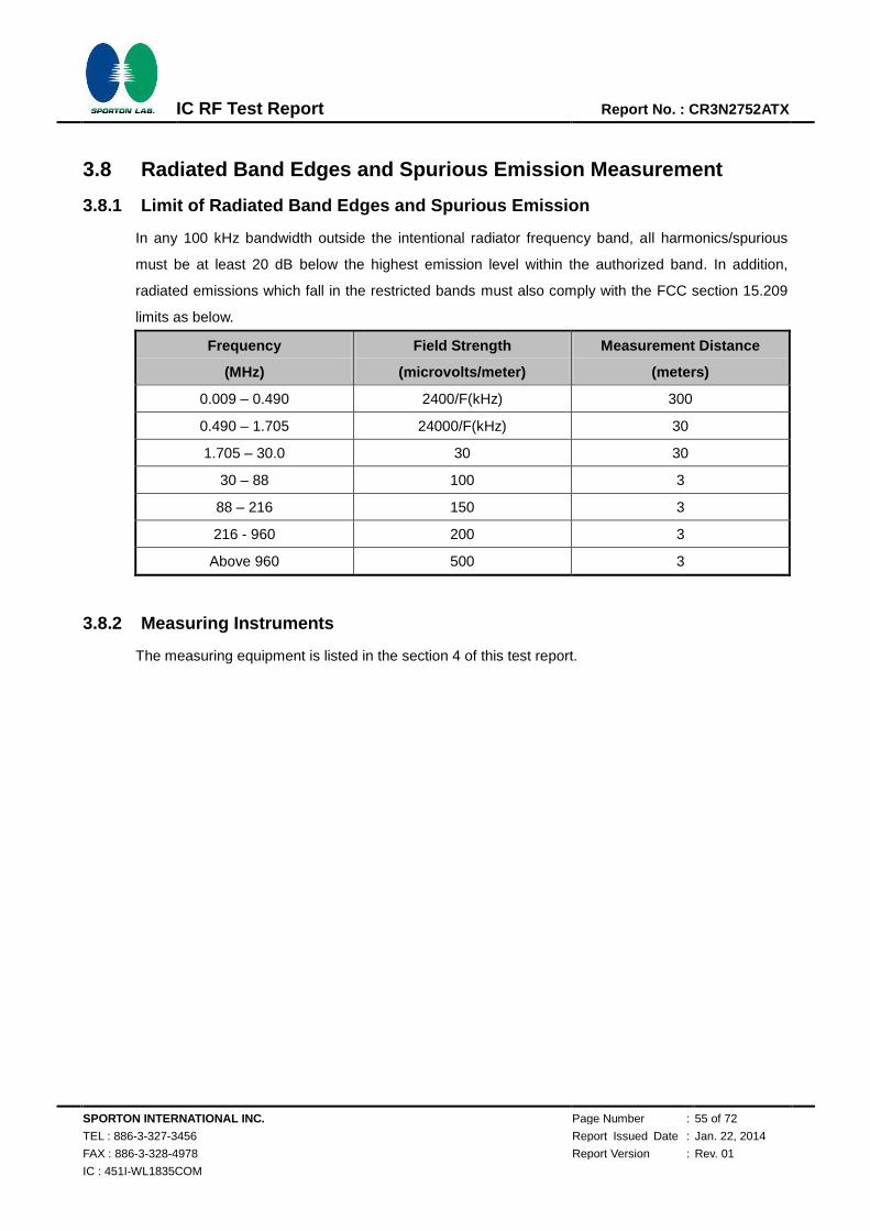
3.8 Radiated Band Edges and Spurious Emission Measurement
3.8.1 Limit of Radiated Band Edges and Spurious Emission
In any 100 kHz bandwidth outside the intentional radiator frequency band, all harmonics/spurious
must be at least 20 dB below the highest emission level within the authorized band. In addition,
radiated emissions which fall in the restricted bands must also comply with the FCC section 15.209
limits as below.
Frequency
(MHz)
Field Strength
(microvolts/meter)
Measurement Distance
(meters)
0.009 – 0.490 2400/F(kHz) 300
0.490 – 1.705 24000/F(kHz) 30
1.705 – 30.0 30 30
30 – 88 100 3
88 – 216 150 3
216 - 960 200 3
Above 960 500 3
3.8.2 Measuring Instruments
The measuring equipment is listed in the section 4 of this test report.
SPORTON INTERNATIONAL INC. Page Number : 56 of 72
TEL : 886-3-327-3456 Report Issued Date : Jan. 22, 2014
FAX : 886-3-328-4978 Report Version : Rev. 01
IC : 451I-WL1835COM
IC RF Test Report Report No. : CR3N2752ATX
3.8.3 Test Procedures
1. The testing follows the guidelines in Spurious Radiated Emissions of FCC Public Notice DA
00-705 Measurement Guidelines.
2. The EUT was placed on a turntable with 0.8 meter above ground.
3. The EUT was set 3 meters from the interference receiving antenna, which was mounted on the
top of a variable height antenna tower.
4. For each suspected emission, the EUT was arranged to its worst case and then tune the
Antenna tower (from 1 m to 4 m) and turntable (from 0 degree to 360 degrees) to find the
maximum reading. A pre-amp and a high pass filter are used for the test in order to get better
signal level to comply with the guidelines.
5. Set to the maximum power setting and enable the EUT transmit continuously.
6. Use the following spectrum analyzer settings:
(1) Span shall wide enough to fully capture the emission being measured;
(2) Set RBW=100 kHz for f < 1 GHz, RBW=1MHz for f>1GHz ; VBW RBW; Sweep = auto;
Detector function = peak; Trace = max hold for peak
(3) For average measurement: use duty cycle correction factor method per 15.35(c).
Duty cycle = On time/100 milliseconds
On time = N1*L1+N2*L2+...+Nn-1*LNn-1+Nn*Ln
Where N1 is number of type 1 pulses, L1 is length of type 1 pulses, etc.
Average Emission Level = Peak Emission Level + 20*log(Duty cycle)
7. Corrected Reading: Antenna Factor + Cable Loss + Read Level - Preamp Factor = Level
Note: The average levels were calculated from the peak level corrected with duty cycle correction
factor (-24.79dB) derived from 20log (dwell time/100ms). This correction is only for signals that hop
with the fundamental signal, such as band-edge and harmonic. Other spurious signals that are
independent of the hopping signal would not use this correction.

SPORTON INTERNATIONAL INC. Page Number : 57 of 72
TEL : 886-3-327-3456 Report Issued Date : Jan. 22, 2014
FAX : 886-3-328-4978 Report Version : Rev. 01
IC : 451I-WL1835COM
IC RF Test Report Report No. : CR3N2752ATX
3.8.4 Test Setup
For radiated emissions below 30MHz
For radiated emissions from 30MHz to 1GHz
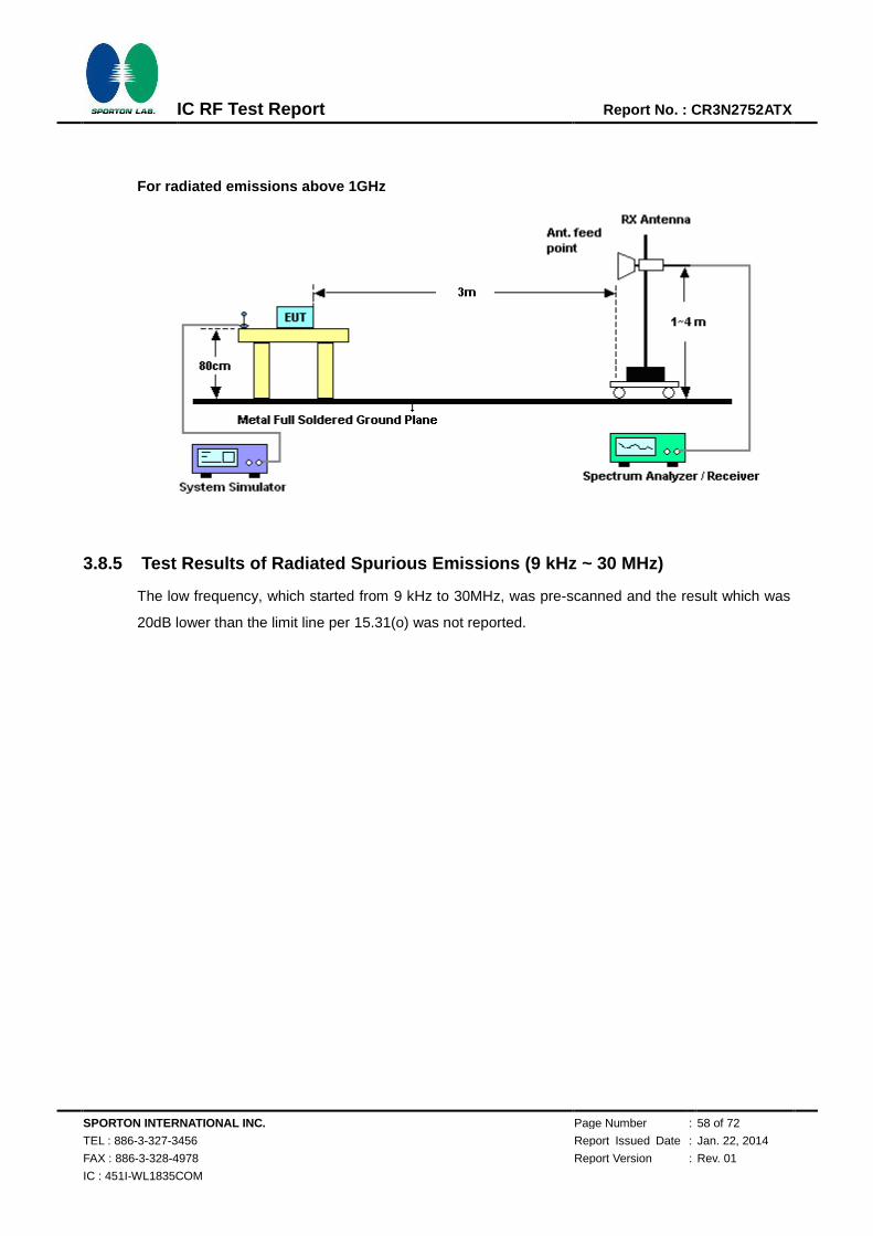
SPORTON INTERNATIONAL INC. Page Number : 58 of 72
TEL : 886-3-327-3456 Report Issued Date : Jan. 22, 2014
FAX : 886-3-328-4978 Report Version : Rev. 01
IC : 451I-WL1835COM
IC RF Test Report Report No. : CR3N2752ATX
For radiated emissions above 1GHz
3.8.5 Test Results of Radiated Spurious Emissions (9 kHz ~ 30 MHz)
The low frequency, which started from 9 kHz to 30MHz, was pre-scanned and the result which was
20dB lower than the limit line per 15.31(o) was not reported.

SPORTON INTERNATIONAL INC. Page Number : 59 of 72
TEL : 886-3-327-3456 Report Issued Date : Jan. 22, 2014
FAX : 886-3-328-4978 Report Version : Rev. 01
IC : 451I-WL1835COM
IC RF Test Report Report No. : CR3N2752ATX
3.8.6 Duty cycle correction factor for average measurement
DH5 on time (One Pulse) Plot on Channel 39
DH5 on time (Count Pulses) Plot on Channel 39
Note:
1. Worst case Duty cycle = on time/100 milliseconds = 2 * 2.88 / 100 = 5.76 %
2. Worst case Duty cycle correction factor = 20*log(Duty cycle) = -24.79 dB
3. DH5 has the highest duty cycle worst case and is reported.
720510
720510
SPORTON INTERNATIONAL INC. Page Number : 60 of 72
TEL : 886-3-327-3456 Report Issued Date : Jan. 22, 2014
FAX : 886-3-328-4978 Report Version : Rev. 01
IC : 451I-WL1835COM
IC RF Test Report Report No. : CR3N2752ATX
Duty Cycle Correction Factor Consideration for AFH mode:
Bluetooth normal hopping rate is 1600Hz and reduced to 800Hz in AFH mode; due to the reduced number of
hopping frequencies, with the same packet configuration the dwell time in each channel frequency within
100msec period is longer in AFH mode than normal mode.
In AFH mode, the minimum hopping frequencies are 20, to get the longest dwell time DH5 packet is observed;
the period to have DH5 packet completing one hopping sequence is
2.88 ms x 20 channels = 57.6 ms
There cannot be 2 complete hopping sequences within 100ms period, considering the random hopping
behavior, maximum 2 hops can be possibly observed within the period. [100ms / 57.6ms ] = 2 hops
Thus, the maximum possible ON time:
2.88 ms x 2 = 5.76 ms
Worst case Duty Cycle Correction factor, which is derived from the maximum possible ON time,
20 x log(5.76 ms/100ms) = -24.79 dB
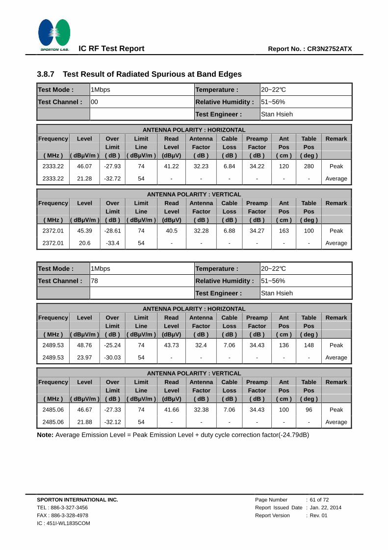
SPORTON INTERNATIONAL INC. Page Number : 61 of 72
TEL : 886-3-327-3456 Report Issued Date : Jan. 22, 2014
FAX : 886-3-328-4978 Report Version : Rev. 01
IC : 451I-WL1835COM
IC RF Test Report Report No. : CR3N2752ATX
3.8.7 Test Result of Radiated Spurious at Band Edges
Test Mode : 1Mbps Temperature : 20~22°C
Test Channel : 00 Relative Humidity : 51~56%
Test Engineer : Stan Hsieh
ANTENNA POLARITY : HORIZONTAL
Frequency Level Over Limit Read Antenna Cable Preamp Ant Table Remark Limit Line Level Factor Loss Factor Pos Pos
( MHz ) ( dBμV/m ) ( dB ) ( dBμV/m ) (dBμV) ( dB ) ( dB ) ( dB ) ( cm ) ( deg )
2333.22 46.07 -27.93 74 41.22 32.23 6.84 34.22 120 280 Peak
2333.22 21.28 -32.72 54 - - - - - - Average
ANTENNA POLARITY : VERTICAL Frequency Level Over Limit Read Antenna Cable Preamp Ant Table Remark
Limit Line Level Factor Loss Factor Pos Pos ( MHz ) ( dBμV/m ) ( dB ) ( dBμV/m ) (dBμV) ( dB ) ( dB ) ( dB ) ( cm ) ( deg )
2372.01 45.39 -28.61 74 40.5 32.28 6.88 34.27 163 100 Peak
2372.01 20.6 -33.4 54 - - - - - - Average
Test Mode : 1Mbps Temperature : 20~22°C
Test Channel : 78 Relative Humidity : 51~56%
Test Engineer : Stan Hsieh
ANTENNA POLARITY : HORIZONTAL
Frequency Level Over Limit Read Antenna Cable Preamp Ant Table Remark Limit Line Level Factor Loss Factor Pos Pos
( MHz ) ( dBμV/m ) ( dB ) ( dBμV/m ) (dBμV) ( dB ) ( dB ) ( dB ) ( cm ) ( deg )
2489.53 48.76 -25.24 74 43.73 32.4 7.06 34.43 136 148 Peak
2489.53 23.97 -30.03 54 - - - - - - Average
ANTENNA POLARITY : VERTICAL Frequency Level Over Limit Read Antenna Cable Preamp Ant Table Remark
Limit Line Level Factor Loss Factor Pos Pos ( MHz ) ( dBμV/m ) ( dB ) ( dBμV/m ) (dBμV) ( dB ) ( dB ) ( dB ) ( cm ) ( deg )
2485.06 46.67 -27.33 74 41.66 32.38 7.06 34.43 100 96 Peak
2485.06 21.88 -32.12 54 - - - - - - Average
Note: Average Emission Level = Peak Emission Level + duty cycle correction factor(-24.79dB)
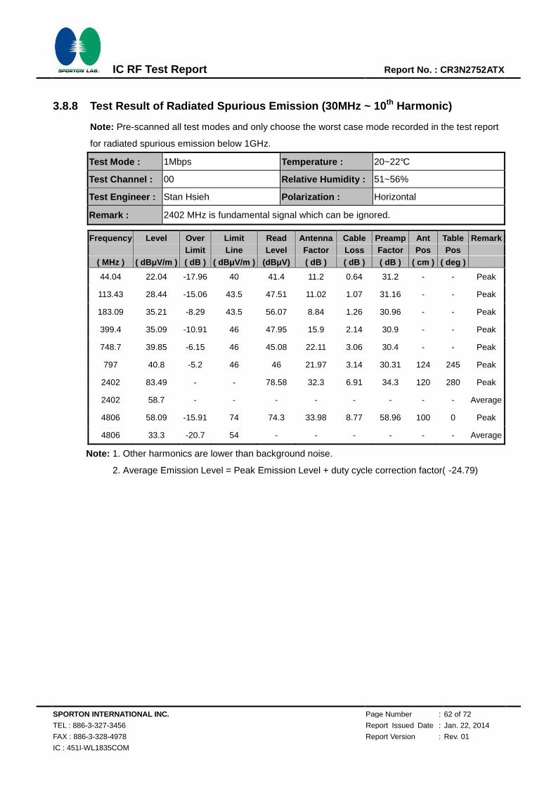
SPORTON INTERNATIONAL INC. Page Number : 62 of 72
TEL : 886-3-327-3456 Report Issued Date : Jan. 22, 2014
FAX : 886-3-328-4978 Report Version : Rev. 01
IC : 451I-WL1835COM
IC RF Test Report Report No. : CR3N2752ATX
3.8.8 Test Result of Radiated Spurious Emission (30MHz ~ 10th Harmonic)
Note: Pre-scanned all test modes and only choose the worst case mode recorded in the test report
for radiated spurious emission below 1GHz.
Test Mode : 1Mbps Temperature : 20~22°C
Test Channel : 00 Relative Humidity : 51~56%
Test Engineer : Stan Hsieh Polarization : Horizontal
Remark : 2402 MHz is fundamental signal which can be ignored.
Frequency Level Over Limit Read Antenna Cable Preamp Ant Table Remark Limit Line Level Factor Loss Factor Pos Pos
( MHz ) ( dBμV/m ) ( dB ) ( dBμV/m ) (dBμV) ( dB ) ( dB ) ( dB ) ( cm ) ( deg )
44.04 22.04 -17.96 40 41.4 11.2 0.64 31.2 - - Peak
113.43 28.44 -15.06 43.5 47.51 11.02 1.07 31.16 - - Peak
183.09 35.21 -8.29 43.5 56.07 8.84 1.26 30.96 - - Peak
399.4 35.09 -10.91 46 47.95 15.9 2.14 30.9 - - Peak
748.7 39.85 -6.15 46 45.08 22.11 3.06 30.4 - - Peak
797 40.8 -5.2 46 46 21.97 3.14 30.31 124 245 Peak
2402 83.49 - - 78.58 32.3 6.91 34.3 120 280 Peak
2402 58.7 - - - - - - - - Average
4806 58.09 -15.91 74 74.3 33.98 8.77 58.96 100 0 Peak
4806 33.3 -20.7 54 - - - - - - Average
Note: 1. Other harmonics are lower than background noise.
2. Average Emission Level = Peak Emission Level + duty cycle correction factor( -24.79)
720510
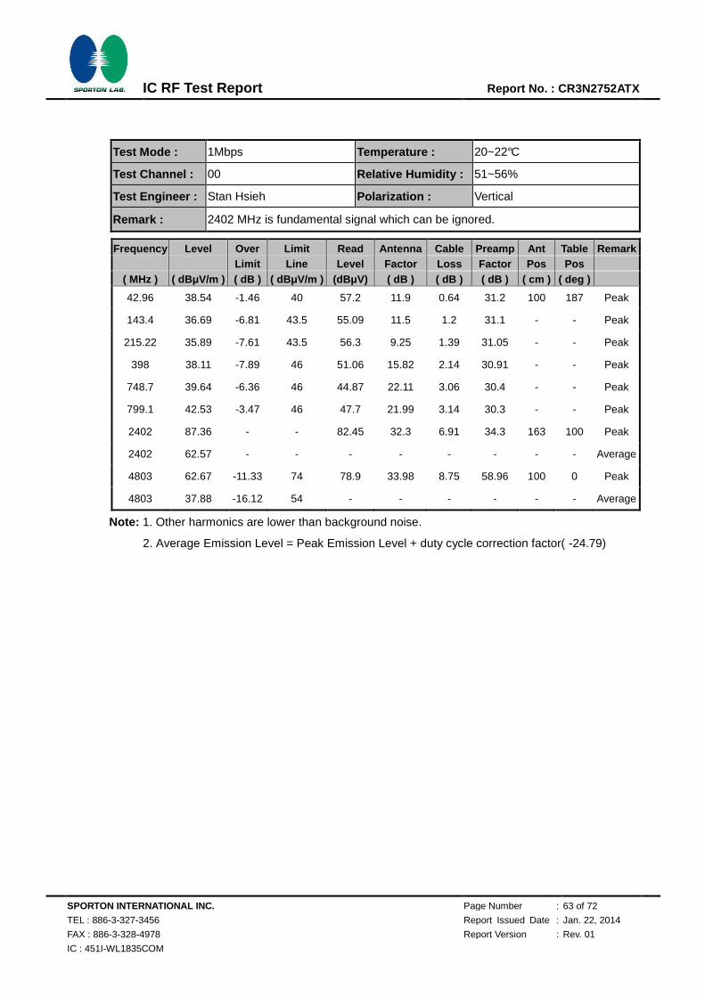
SPORTON INTERNATIONAL INC. Page Number : 63 of 72
TEL : 886-3-327-3456 Report Issued Date : Jan. 22, 2014
FAX : 886-3-328-4978 Report Version : Rev. 01
IC : 451I-WL1835COM
IC RF Test Report Report No. : CR3N2752ATX
Test Mode : 1Mbps Temperature : 20~22°C
Test Channel : 00 Relative Humidity : 51~56%
Test Engineer : Stan Hsieh Polarization : Vertical
Remark : 2402 MHz is fundamental signal which can be ignored.
Frequency Level Over Limit Read Antenna Cable Preamp Ant Table Remark Limit Line Level Factor Loss Factor Pos Pos
( MHz ) ( dBμV/m ) ( dB ) ( dBμV/m ) (dBμV) ( dB ) ( dB ) ( dB ) ( cm ) ( deg )
42.96 38.54 -1.46 40 57.2 11.9 0.64 31.2 100 187 Peak
143.4 36.69 -6.81 43.5 55.09 11.5 1.2 31.1 - - Peak
215.22 35.89 -7.61 43.5 56.3 9.25 1.39 31.05 - - Peak
398 38.11 -7.89 46 51.06 15.82 2.14 30.91 - - Peak
748.7 39.64 -6.36 46 44.87 22.11 3.06 30.4 - - Peak
799.1 42.53 -3.47 46 47.7 21.99 3.14 30.3 - - Peak
2402 87.36 - - 82.45 32.3 6.91 34.3 163 100 Peak
2402 62.57 - - - - - - - - Average
4803 62.67 -11.33 74 78.9 33.98 8.75 58.96 100 0 Peak
4803 37.88 -16.12 54 - - - - - - Average
Note: 1. Other harmonics are lower than background noise.
2. Average Emission Level = Peak Emission Level + duty cycle correction factor( -24.79)
720510
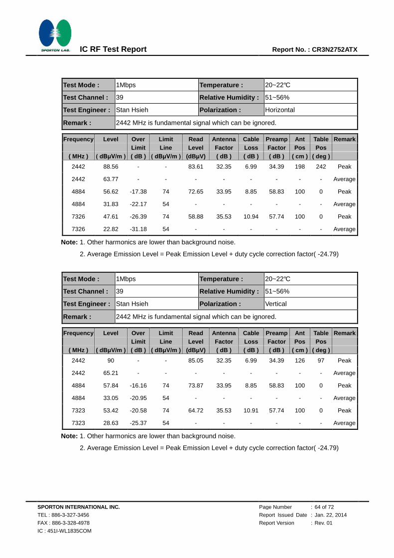
SPORTON INTERNATIONAL INC. Page Number : 64 of 72
TEL : 886-3-327-3456 Report Issued Date : Jan. 22, 2014
FAX : 886-3-328-4978 Report Version : Rev. 01
IC : 451I-WL1835COM
IC RF Test Report Report No. : CR3N2752ATX
Test Mode : 1Mbps Temperature : 20~22°C
Test Channel : 39 Relative Humidity : 51~56%
Test Engineer : Stan Hsieh Polarization : Horizontal
Remark : 2442 MHz is fundamental signal which can be ignored.
Frequency Level Over Limit Read Antenna Cable Preamp Ant Table Remark Limit Line Level Factor Loss Factor Pos Pos
( MHz ) ( dBμV/m ) ( dB ) ( dBμV/m ) (dBμV) ( dB ) ( dB ) ( dB ) ( cm ) ( deg )
2442 88.56 - - 83.61 32.35 6.99 34.39 198 242 Peak
2442 63.77 - - - - - - - - Average
4884 56.62 -17.38 74 72.65 33.95 8.85 58.83 100 0 Peak
4884 31.83 -22.17 54 - - - - - - Average
7326 47.61 -26.39 74 58.88 35.53 10.94 57.74 100 0 Peak
7326 22.82 -31.18 54 - - - - - - Average
Note: 1. Other harmonics are lower than background noise.
2. Average Emission Level = Peak Emission Level + duty cycle correction factor( -24.79)
Test Mode : 1Mbps Temperature : 20~22°C
Test Channel : 39 Relative Humidity : 51~56%
Test Engineer : Stan Hsieh Polarization : Vertical
Remark : 2442 MHz is fundamental signal which can be ignored.
Frequency Level Over Limit Read Antenna Cable Preamp Ant Table Remark Limit Line Level Factor Loss Factor Pos Pos
( MHz ) ( dBμV/m ) ( dB ) ( dBμV/m ) (dBμV) ( dB ) ( dB ) ( dB ) ( cm ) ( deg )
2442 90 - - 85.05 32.35 6.99 34.39 126 97 Peak
2442 65.21 - - - - - - - - Average
4884 57.84 -16.16 74 73.87 33.95 8.85 58.83 100 0 Peak
4884 33.05 -20.95 54 - - - - - - Average
7323 53.42 -20.58 74 64.72 35.53 10.91 57.74 100 0 Peak
7323 28.63 -25.37 54 - - - - - - Average
Note: 1. Other harmonics are lower than background noise.
2. Average Emission Level = Peak Emission Level + duty cycle correction factor( -24.79)
720510
720510

SPORTON INTERNATIONAL INC. Page Number : 65 of 72
TEL : 886-3-327-3456 Report Issued Date : Jan. 22, 2014
FAX : 886-3-328-4978 Report Version : Rev. 01
IC : 451I-WL1835COM
IC RF Test Report Report No. : CR3N2752ATX
Test Mode : 1Mbps Temperature : 20~22°C
Test Channel : 78 Relative Humidity : 51~56%
Test Engineer : Stan Hsieh Polarization : Horizontal
Remark : 2480 MHz is fundamental signal which can be ignored.
Frequency Level Over Limit Read Antenna Cable Preamp Ant Table Remark Limit Line Level Factor Loss Factor Pos Pos
( MHz ) ( dBμV/m ) ( dB ) ( dBμV/m ) (dBμV) ( dB ) ( dB ) ( dB ) ( cm ) ( deg )
2480 97.22 - - 92.21 32.38 7.06 34.43 136 148 Peak
2480 72.43 - - - - - - - - Average
4962 56.24 -17.76 74 72.07 33.91 8.92 58.66 100 0 Peak
4962 31.45 -22.55 54 - - - - - - Average
7440 48.26 -25.74 74 59.56 35.51 11.04 57.85 100 0 Peak
7440 23.47 -30.53 54 - - - - - - Average
Note: 1. Other harmonics are lower than background noise.
2. Average Emission Level = Peak Emission Level + duty cycle correction factor( -24.79)
Test Mode : 1Mbps Temperature : 20~22°C
Test Channel : 78 Relative Humidity : 51~56%
Test Engineer : Stan Hsieh Polarization : Vertical
Remark : 2480 MHz is fundamental signal which can be ignored.
Frequency Level Over Limit Read Antenna Cable Preamp Ant Table Remark Limit Line Level Factor Loss Factor Pos Pos
( MHz ) ( dBμV/m ) ( dB ) ( dBμV/m ) (dBμV) ( dB ) ( dB ) ( dB ) ( cm ) ( deg )
2480 93.22 - - 88.21 32.38 7.06 34.43 100 96 Peak
2480 68.43 - - - - - - - - Average
4962 57.78 -16.22 74 73.61 33.91 8.92 58.66 100 0 Peak
4962 32.99 -21.01 54 - - - - - - Average
7440 53.66 -20.34 74 64.96 35.51 11.04 57.85 100 0 Peak
7440 28.87 -25.13 54 - - - - - - Average
Note: 1. Other harmonics are lower than background noise.
2. Average Emission Level = Peak Emission Level + duty cycle correction factor( -24.79)
720510
720510
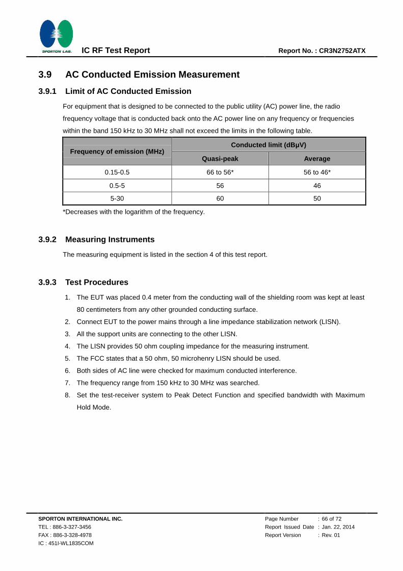
SPORTON INTERNATIONAL INC. Page Number : 66 of 72
TEL : 886-3-327-3456 Report Issued Date : Jan. 22, 2014
FAX : 886-3-328-4978 Report Version : Rev. 01
IC : 451I-WL1835COM
IC RF Test Report Report No. : CR3N2752ATX
3.9 AC Conducted Emission Measurement
3.9.1 Limit of AC Conducted Emission
For equipment that is designed to be connected to the public utility (AC) power line, the radio
frequency voltage that is conducted back onto the AC power line on any frequency or frequencies
within the band 150 kHz to 30 MHz shall not exceed the limits in the following table.
Frequency of emission (MHz) Conducted limit (dBμV)
Quasi-peak Average
0.15-0.5 66 to 56* 56 to 46*
0.5-5 56 46
5-30 60 50
*Decreases with the logarithm of the frequency.
3.9.2 Measuring Instruments
The measuring equipment is listed in the section 4 of this test report.
3.9.3 Test Procedures
1. The EUT was placed 0.4 meter from the conducting wall of the shielding room was kept at least
80 centimeters from any other grounded conducting surface.
2. Connect EUT to the power mains through a line impedance stabilization network (LISN).
3. All the support units are connecting to the other LISN.
4. The LISN provides 50 ohm coupling impedance for the measuring instrument.
5. The FCC states that a 50 ohm, 50 microhenry LISN should be used.
6. Both sides of AC line were checked for maximum conducted interference.
7. The frequency range from 150 kHz to 30 MHz was searched.
8. Set the test-receiver system to Peak Detect Function and specified bandwidth with Maximum
Hold Mode.
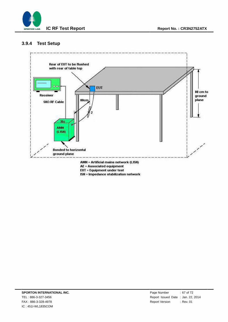
SPORTON INTERNATIONAL INC. Page Number : 67 of 72
TEL : 886-3-327-3456 Report Issued Date : Jan. 22, 2014
FAX : 886-3-328-4978 Report Version : Rev. 01
IC : 451I-WL1835COM
IC RF Test Report Report No. : CR3N2752ATX
3.9.4 Test Setup

SPORTON INTERNATIONAL INC. Page Number : 68 of 72
TEL : 886-3-327-3456 Report Issued Date : Jan. 22, 2014
FAX : 886-3-328-4978 Report Version : Rev. 01
IC : 451I-WL1835COM
IC RF Test Report Report No. : CR3N2752ATX
3.9.5 Test Result of AC Conducted Emission
Test Mode : Mode 1 Temperature : 20~22℃
Test Engineer : Cosmo Xu Relative Humidity : 45~47%
Test Voltage : 120Vac / 60Hz Phase : Line
Function Type : WLAN Link + Bluetooth Link + Adapter
Final Result : Quasi-Peak
Frequency
(MHz)
Quasi-Peak
(dBµV) Filter Line
Corr.
(dB)
Margin
(dB)
Limit
(dBµV)
0.150000 51.8 Off L1 19.4 14.2 66.0
0.190000 43.4 Off L1 19.4 20.6 64.0
0.286000 40.0 Off L1 19.4 20.6 60.6
0.342000 44.2 Off L1 19.4 15.0 59.2
0.558000 38.7 Off L1 19.4 17.3 56.0
2.630000 37.5 Off L1 19.6 18.5 56.0
Final Result : Average
Frequency
(MHz)
Average
(dBµV) Filter Line
Corr.
(dB)
Margin
(dB)
Limit
(dBµV)
0.150000 41.1 Off L1 19.4 14.9 56.0
0.190000 32.8 Off L1 19.4 21.2 54.0
0.286000 36.5 Off L1 19.4 14.1 50.6
0.342000 40.5 Off L1 19.4 8.7 49.2
0.558000 33.2 Off L1 19.4 12.8 46.0
2.630000 31.4 Off L1 19.6 14.6 46.0

SPORTON INTERNATIONAL INC. Page Number : 69 of 72
TEL : 886-3-327-3456 Report Issued Date : Jan. 22, 2014
FAX : 886-3-328-4978 Report Version : Rev. 01
IC : 451I-WL1835COM
IC RF Test Report Report No. : CR3N2752ATX
Test Mode : Mode 1 Temperature : 20~22℃
Test Engineer : Cosmo Xu Relative Humidity : 45~47%
Test Voltage : 120Vac / 60Hz Phase : Neutral
Function Type : WLAN Link + Bluetooth Link + Adapter
Final Result : Quasi-Peak
Frequency
(MHz)
Quasi-Peak
(dBµV) Filter Line
Corr.
(dB)
Margin
(dB)
Limit
(dBµV)
0.150000 53.5 Off N 19.4 12.5 66.0
0.198000 42.2 Off N 19.3 21.5 63.7
0.350000 43.8 Off N 19.4 15.2 59.0
0.550000 39.7 Off N 19.4 16.3 56.0
0.990000 37.8 Off N 19.4 18.2 56.0
2.574000 38.2 Off N 19.6 17.8 56.0
Final Result : Average
Frequency
(MHz)
Average
(dBµV) Filter Line
Corr.
(dB)
Margin
(dB)
Limit
(dBµV)
0.150000 38.4 Off N 19.4 17.6 56.0
0.198000 31.5 Off N 19.3 22.2 53.7
0.350000 40.5 Off N 19.4 8.5 49.0
0.550000 34.9 Off N 19.4 11.1 46.0
0.990000 30.9 Off N 19.4 15.1 46.0
2.574000 32.6 Off N 19.6 13.4 46.0

SPORTON INTERNATIONAL INC. Page Number : 70 of 72
TEL : 886-3-327-3456 Report Issued Date : Jan. 22, 2014
FAX : 886-3-328-4978 Report Version : Rev. 01
IC : 451I-WL1835COM
IC RF Test Report Report No. : CR3N2752ATX
3.10 Antenna Requirements
3.10.1 Standard Applicable
If directional gain of transmitting antennas is greater than 6dBi, the power shall be reduced by the
same level in dB comparing to gain minus 6dBi. The use of a permanently attached antenna or of an
antenna that uses a unique coupling to the intentional radiator shall be considered sufficient to
comply with the FCC rule.
3.10.2 Antenna Anti-Replacement Construction
Non-standard antenna connector is used.
3.10.3 Antenna Gain
The antenna peak gain of EUT is less than 6 dBi. Therefore, it is not necessary to reduce maximum
peak output power limit.

SPORTON INTERNATIONAL INC. Page Number : 71 of 72
TEL : 886-3-327-3456 Report Issued Date : Jan. 22, 2014
FAX : 886-3-328-4978 Report Version : Rev. 01
IC : 451I-WL1835COM
IC RF Test Report Report No. : CR3N2752ATX
4 List of Measuring Equipment
Instrument Manufacturer Model No. Serial No. Characteristics Calibration
Date Test Date Due Date Remark
Spectrum
Analyzer
Rohde &
Schwarz FSP40 100055 9kHz~40GHz Jun. 07, 2013
Dec. 04, 2013~
Dec. 10, 2013 Jun. 06, 2014
Conducted
(TH02-HY)
Power Meter Agilent E4416A GB4129234
4 300MHz~40GHz Feb. 05, 2013
Dec. 04, 2013~
Dec. 10, 2013 Feb. 04, 2014
Conducted
(TH02-HY)
Power Sensor Agilent E9327A US40441548 300MHz~40GHz Feb. 05, 2013 Dec. 04, 2013~
Dec. 10, 2013 Feb. 04, 2014
Conducted
(TH02-HY)
EMI Test Receiver Rohde &
Schwarz ESCI 7 100724 9 kHz~7 GHz Sep. 06, 2013
Dec. 11, 2013~
Dec. 12, 2013 Sep. 05, 2014
Radiation
(03CH07-HY)
Spectrum
Analyzer
Rohde &
Schwarz FSP30 101067 9 kHz ~ 30 GHz Nov. 20, 2013
Dec. 11, 2013~
Dec. 12, 2013 Nov. 19, 2014
Radiation
(03CH07-HY)
Loop Antenna Rohde &
Schwarz HFH2-Z2 860004/0001 9 kHz~30 Mhz Jul. 03, 2012
Dec. 11, 2013~
Dec. 12, 2013 Jul. 03, 2014
Radiation
(03CH07-HY)
Bilog Antenna Schaffner CBL6111C 2726 30 MHz ~ 1 GHz Oct. 10, 2013 Dec. 11, 2013~
Dec. 12, 2013 Oct. 09, 2014
Radiation
(03CH07-HY)
Double Ridge
Horn Antenna ESCO 3117 75962 1 GHz~18 GHz Aug. 22, 2013
Dec. 11, 2013~
Dec. 12, 2013 Aug. 21, 2014
Radiation
(03CH07-HY)
SHF-EHF Horn
Antenna
SCHWARZBE
CK BBHA 9170
BBHA91702
51 15 GHz- 40 GHz Oct. 03, 2013
Dec. 11, 2013~
Dec. 12, 2013 Oct. 02, 2014
Radiation
(03CH07-HY)
Preamplifier COM-POWER PA-103A 161241 30 MHz~1 GHz Feb. 26, 2013 Dec. 11, 2013~
Dec. 12, 2013 Feb. 25, 2014
Radiation
(03CH07-HY)
Preamplifier Agilent 8449B 3008A01917 1 GHz~26.5 GHz Aug. 12, 2013 Dec. 11, 2013~
Dec. 12, 2013 Aug. 11, 2014
Radiation
(03CH07-HY)
Preamplifier MITEQ
AMF-7D-00
101800-30-
10P
159088 DC~18 G High
Gain Feb. 27, 2013
Dec. 11, 2013~
Dec. 12, 2013 Feb. 26, 2014
Radiation
(03CH07-HY)
Turn Table ChainTek ChainTek
3000 N/A 0 ~ 360 degree N/A
Dec. 11, 2013~
Dec. 12, 2013 N/A
Radiation
(03CH07-HY)
Antenna Mast ChainTek ChainTek
3000 N/A N/A N/A
Dec. 11, 2013~
Dec. 12, 2013 N/A
Radiation
(03CH07-HY)
EMI Test Receiver Rohde &
Schwarz ESCS 30 100356 9kHz ~ 2.75GHz Nov. 15, 2013 Dec. 10, 2013 Nov. 14, 2014
Conduction
(CO05-HY)
Two-LISN
(for auxiliary
equipment)
Rohde &
Schwarz ENV216 100081 9kHz ~ 30MHz Dec. 12, 2013 Dec. 10, 2013 Dec. 11, 2014
Conduction
(CO05-HY)
Two-LISN Rohde &
Schwarz ENV216 100080 9kHz ~ 30MHz Dec. 04, 2013 Dec. 10, 2013 Dec. 03, 2014
Conduction
(CO05-HY)
AC Power Source APC APC-1000
W N/A N/A N/A Dec. 10, 2013 N/A
Conduction
(CO05-HY)

SPORTON INTERNATIONAL INC. Page Number : 72 of 72
TEL : 886-3-327-3456 Report Issued Date : Jan. 22, 2014
FAX : 886-3-328-4978 Report Version : Rev. 01
IC : 451I-WL1835COM
IC RF Test Report Report No. : CR3N2752ATX
5 Uncertainty of Evaluation
Uncertainty of Conducted Emission Measurement (150 kHz ~ 30 MHz)
Measuring Uncertainty for a Level of Confidence of 95% (U = 2Uc(y))
2.26
Uncertainty of Radiated Emission Measurement (30 MHz ~ 1000 MHz)
Measuring Uncertainty for a Level of Confidence of 95% (U = 2Uc(y))
4.50

SPORTON INTERNATIONAL INC. Page Number : A1 of A2
TEL : 886-3-327-3456 Report Issued Date : Jan. 22, 2014
FAX : 886-3-328-4978 Report Version : Rev. 01
IC : 451I-WL1835COM
IC RF Test Report Report No. : CR3N2752ATX
Appendix A. Setup Photographs
<Conducted Emission>

SPORTON INTERNATIONAL INC. Page Number : A2 of A2
TEL : 886-3-327-3456 Report Issued Date : Jan. 22, 2014
FAX : 886-3-328-4978 Report Version : Rev. 01
IC : 451I-WL1835COM
IC RF Test Report Report No. : CR3N2752ATX
<Radiated Emission>
LF
HF