rf semiconductor test
TRANSCRIPT
Cobham Wireless - Validation Part Number 46900-095 Issue 1
www.cobham.com/wireless
The most important thing we build is trust
RF Semiconductor Test AXRF-Q Multi-Port PXI RF Sub-System Datasheet
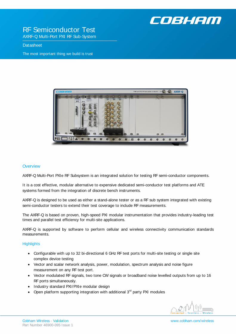
Overview AXRF-Q Multi-Port PXIe RF Subsystem is an integrated solution for testing RF semi-conductor components.
It is a cost effective, modular alternative to expensive dedicated semi-conductor test platforms and ATE systems formed from the integration of discrete bench instruments.
AXRF-Q is designed to be used as either a stand-alone tester or as a RF sub system integrated with existing semi-conductor testers to extend their test coverage to include RF measurements.
The AXRF-Q is based on proven, high-speed PXI modular instrumentation that provides industry-leading test times and parallel test efficiency for multi-site applications. AXRF-Q is supported by software to perform cellular and wireless connectivity communication standards measurements. Highlights
• Configurable with up to 32 bi-directional 6 GHz RF test ports for multi-site testing or single site complex device testing
• Vector and scalar network analysis, power, modulation, spectrum analysis and noise figure measurement on any RF test port.
• Vector modulated RF signals, two tone CW signals or broadband noise levelled outputs from up to 16 RF ports simultaneously.
• Industry standard PXI/PXIe modular design • Open platform supporting integration with additional 3rd party PXI modules
AXRF-Q Datasheet
Cobham Wireless - Validation Part Number 46900-095, Issue 1
www.cobham.com/wireless
Applications
• Single / multi-site production and design characterisation testing of o Discrete RF components o Multi-mode multi-band power amplifiers (MMMB) o Front End Modules o Switches o Transceivers
OEM RF sub-system for SOC, uController device test Measurements
• S11, S12, S22, S21 • Return Loss • Noise Figure, Gain • Modulation Quality1
o EVM, RCE, Rho, phase/amplitude error, skew, gain imbalance, carrier leak • Spectral emissions2
o ACPR, OBW, SEM Performance
• 65 MHz to 6 GHz o Frequency settling time <400 µs
• RF output level up to +15 dBm (PEP) with:- o 0.01 dB resolution o Amplitude settling time <50 µs o CW or IQ modulated o Residual EVM better than 1%3 o Repeatability <0.02 dB o Accuracy <0.5 dB o Return Loss >20 dB
• RF input level -45dBm to +20 dBm with:- o Noise floor @ -154 dBm/Hz o Return Loss >20dB o Port to Port isolation better than 80 dB o Residual EVM better than 1%
• Instantaneous I/O signal bandwidth 200 MHz • Scalar measurement repeatability 0.05 dB • NF measurement to 2 dB • S11, S22 measurements with 0.4 dB/2.5 deg repeatability • S12, S21 measurement with 0.1 dB/2.0 deg repeatability
1 When the requisite option is enabled. Methods in accordance with those published 3GPP, 3GPP2, IEEE communications standard. 2 As above 3 WLAN 11ac VHT80 MCS9 @ 5.8 GHz, equalisation = pre-amble only, phase tracking enabled
AXRF-Q Datasheet
Cobham Wireless - Validation Part Number 46900-095, Issue 1
www.cobham.com/wireless
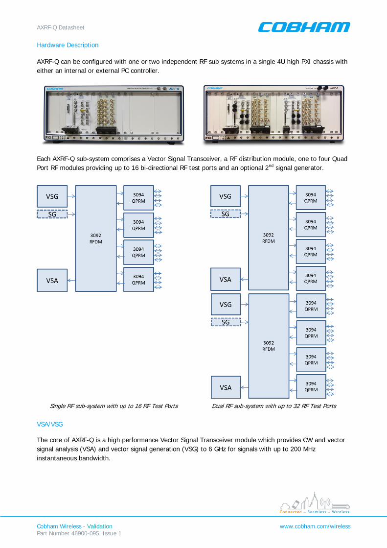
Hardware Description AXRF-Q can be configured with one or two independent RF sub systems in a single 4U high PXI chassis with either an internal or external PC controller.
Each AXRF-Q sub-system comprises a Vector Signal Transceiver, a RF distribution module, one to four Quad Port RF modules providing up to 16 bi-directional RF test ports and an optional 2nd signal generator.
Single RF sub-system with up to 16 RF Test Ports Dual RF sub-system with up to 32 RF Test Ports
VSA/VSG The core of AXRF-Q is a high performance Vector Signal Transceiver module which provides CW and vector signal analysis (VSA) and vector signal generation (VSG) to 6 GHz for signals with up to 200 MHz instantaneous bandwidth.
AXRF-Q Datasheet
Cobham Wireless - Validation Part Number 46900-095, Issue 1
www.cobham.com/wireless
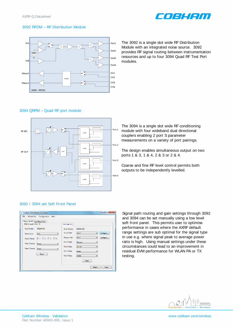
3092 RFDM – RF Distribution Module
The 3092 is a single slot wide RF Distribution Module with an integrated noise source. 3092 provides RF signal routing between instrumentation resources and up to four 3094 Quad RF Test Port modules.
3094 QRPM – Quad RF port module
The 3094 is a single slot wide RF conditioning module with four wideband dual directional couplers enabling 2 port S parameter measurements on a variety of port pairings.
The design enables simultaneous output on two ports 1 & 3, 1 & 4, 2 & 3 or 2 & 4.
Coarse and fine RF level control permits both outputs to be independently levelled.
3092 / 3094 set Soft Front Panel
Signal path routing and gain settings through 3092 and 3094 can be set manually using a low level soft front panel. This permits user to optimise performance in cases where the AXRF default range settings are sub optimal for the signal type in use e.g. where signal peak to average power ratio is high. Using manual settings under these circumstances could lead to an improvement in residual EVM performance for WLAN PA or TX testing.

AXRF-Q Datasheet
Cobham Wireless - Validation Part Number 46900-095, Issue 1
www.cobham.com/wireless
Operation AXRF is supplied with a high level C / .net programming interface and a soft front panel user interface. The soft front panel permits manual setup of noise figure, scalar or vector 2 port measurements. The UI displays results, traces and statistics for single point or swept measurement.
Scalar Measurements In scalar mode AXRF-Q can perform gain or loss measurement between any 2 RF test ports.
Amplifier gain sweep using scalar mode
S Parameter Measurement In vector mode S parameters can be measured between ports pairs 1-2 and 3-4 on each 3094 module.
Amplifier S parameter measurement sweep
AXRF-Q Datasheet
Cobham Wireless - Validation Part Number 46900-095, Issue 1
www.cobham.com/wireless
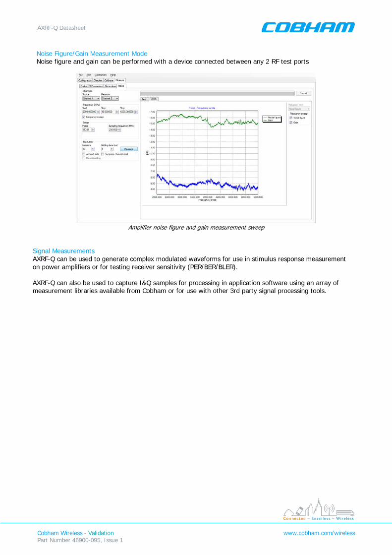
Noise Figure/Gain Measurement Mode Noise figure and gain can be performed with a device connected between any 2 RF test ports
Amplifier noise figure and gain measurement sweep
Signal Measurements AXRF-Q can be used to generate complex modulated waveforms for use in stimulus response measurement on power amplifiers or for testing receiver sensitivity (PER/BER/BLER). AXRF-Q can also be used to capture I&Q samples for processing in application software using an array of measurement libraries available from Cobham or for use with other 3rd party signal processing tools.

AXRF-Q Datasheet
Cobham Wireless - Validation Part Number 46900-095, Issue 1
www.cobham.com/wireless
IQCreator Waveform creation tools for generating waveforms emulating commercial and proprietary radio standards. RF signals can be played out of any AXRF-Q test port and used to stimulate receivers to measure sensitivity or used as input to power amplifiers when characterising output modulation quality, power and spectral containment.
Measurement Libraries Measurements libraries for use in characterising signals in accordance with methods defined by commercial radio standards for use in cellular and wireless connectivity equipment.
LTE FDD/TDD Uplink / Downlink Bluetooth, BR/EDR/LE
UMTS Uplink / Downlink DECT
GSM/EDGE WiMAX OFDMA
cdma2k / EV-DO Reverse link Generic PSK, QAM, FSK, FM
WLAN 802.11a,b,g,n,p,ac Spectrum Analysis
Expansion slots Unused PXI slots are available to the user to populate with 3rd party instrumentation modules.
Calibration AXRF-Q is calibrated in the line periodically using a portable automated calibrator accessory.
AXRF-Q Datasheet
Cobham Wireless - Validation Part Number 46900-095, Issue 1
www.cobham.com/wireless
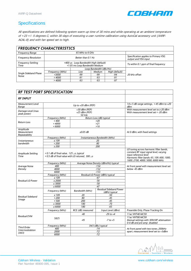
Specifications All specifications are defined following system warm up time of 30 mins and while operating at an ambient temperature of +23 +/- 5 degrees C, within 30 days of executing a user runtime calibration using AutoCal accessory unit (AXRF-ACAL-8) and with fan speed set to high. FREQUENCY CHARACTERISTICS Frequency Range 65 MHz to 6 GHz
Frequency Resolution Better than 0.1 Hz Specification applies to Primary VSG output and VSA input
Frequency Settling Time
<400 us Loop Bandwidth High (default) <1.05 ms Loop Bandwidth Medium To within 0.1 ppm of final frequency
Single Sideband Phase Noise
Loop Bandwidth (dBc/Hz)
20 kHz offset Frequency (MHz) Low Medium High (default)
<3000 -99 -99 -94 < 4000 -91 -93 -91 > 4000 -93 -93 -97
RF TEST PORT SPECIFICATION
RF INPUT
Measurement Level Range Up to +20 dBm (PEP) 14 x 5 dB range settings, <-45 dBm to +20
dBm
Damage Level (max peak power)
+30 dBm (PEP) +25 dBm (PEP)
50 Vdc
With measurement level set to ≥-20 dBm With measurement level set < -20 dBm
Return Loss
Frequency (MHz) Return Loss (dB) typical < 400
< 4000 < 6000
>20 >21 >16
Amplitude Measurement Repeatability
±0.05 dB At 0 dBm, with fixed settings
Instantaneous bandwidth
Frequency (MHz) Instantaneous Bandwidth (MHz)
≤ 109 20 < 200 80 ≥ 200 200
Amplitude Settling Time
< 0.1 dB of final value, 125 μs, typical < 0.5 dB of final value with LO retuned, 300 μs
LO tuning across harmonic filter bands, constant RF input signal level, varying input reference level Harmonic filter bands: 65, 109, 600, 1000, 1600, 2700, 4000, 5000, 6000 MHz
Average Noise Density
Frequency (MHz) Average Noise Density (dBm/Hz) typical At front panel with measurement level set below -45 dBm
400 -154 4000 -152 6000 -153
Residual LO Power
Frequency (MHz) Residual LO Power (dBfs) typical
≤ 109 -67
≤ 2000 -56 ≤ 3000 -58 ≤ 6000 -47
Residual Sideband Image
Frequency (MHz) Bandwidth (MHz) Residual Sideband Power (dBfs) typical
≤ 109 20 -50 < 200 80 -45 < 500 200 -45
≤ 3000 180 -70 ≤ 6000 180 -65
Residual EVM
Frequency (MHz) RCE (dB) measured Input Level (dBm) Preamble Only, Phase Tracking On
5825
-40 -29 to +4 11ac VHT40 MCS9
-45 -7 to +5 11ac VHT80 MCS9 Manual settings with 3094 RF attenuation 0-4 dB and pre-amp disabled
Third Order Intermodulation (IM3)
Frequency (MHz) IM3 (dBc) typical At front panel with two tones, 200kHz apart, measurement level set to +3dBm
400 -74 2000 -72 6000 -72
AXRF-Q Datasheet
Cobham Wireless - Validation Part Number 46900-095, Issue 1
www.cobham.com/wireless
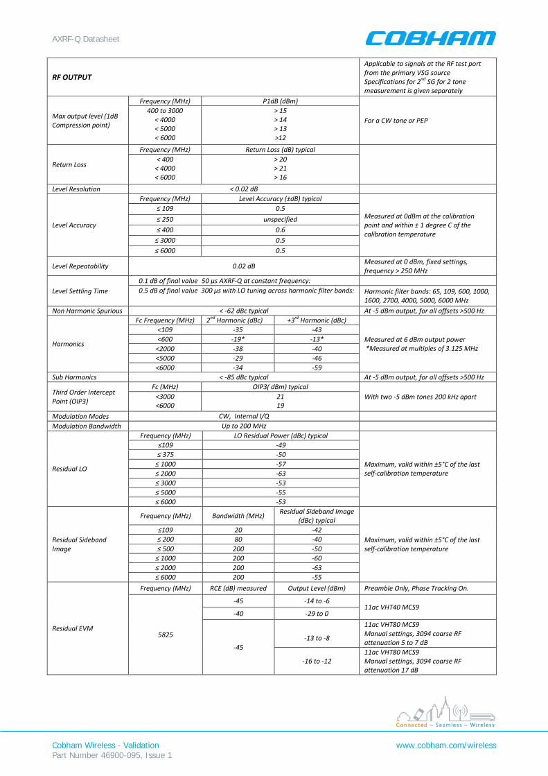
RF OUTPUT
Applicable to signals at the RF test port from the primary VSG source Specifications for 2nd SG for 2 tone measurement is given separately
Max output level (1dB Compression point)
Frequency (MHz) P1dB (dBm)
For a CW tone or PEP 400 to 3000
< 4000 < 5000 < 6000
> 15 > 14 > 13 >12
Return Loss
Frequency (MHz) Return Loss (dB) typical
< 400
< 4000 < 6000
> 20 > 21 > 16
Level Resolution < 0.02 dB
Level Accuracy
Frequency (MHz) Level Accuracy (±dB) typical
Measured at 0dBm at the calibration point and within ± 1 degree C of the calibration temperature
≤ 109 0.5 ≤ 250 unspecified ≤ 400 0.6
≤ 3000 0.5 ≤ 6000 0.5
Level Repeatability 0.02 dB Measured at 0 dBm, fixed settings, frequency > 250 MHz
Level Settling Time 0.1 dB of final value 50 µs AXRF-Q at constant frequency: 0.5 dB of final value 300 µs with LO tuning across harmonic filter bands: Harmonic filter bands: 65, 109, 600, 1000,
1600, 2700, 4000, 5000, 6000 MHz Non Harmonic Spurious < -62 dBc typical At -5 dBm output, for all offsets >500 Hz
Harmonics
Fc Frequency (MHz) 2nd Harmonic (dBc) +3rd Harmonic (dBc)
Measured at 6 dBm output power *Measured at multiples of 3.125 MHz
<109 -35 -43 <600 -19* -13*
<2000 -38 -40 <5000 -29 -46 <6000 -34 -59
Sub Harmonics < -85 dBc typical At -5 dBm output, for all offsets >500 Hz
Third Order Intercept Point (OIP3)
Fc (MHz) OIP3( dBm) typical With two -5 dBm tones 200 kHz apart <3000
<6000 21 19
Modulation Modes CW, Internal I/Q Modulation Bandwidth Up to 200 MHz
Residual LO
Frequency (MHz) LO Residual Power (dBc) typical
Maximum, valid within ±5°C of the last self-calibration temperature
≤109 -49 ≤ 375 -50
≤ 1000 -57 ≤ 2000 -63 ≤ 3000 -53 ≤ 5000 -55 ≤ 6000 -53
Residual Sideband Image
Frequency (MHz) Bandwidth (MHz) Residual Sideband Image (dBc) typical
Maximum, valid within ±5°C of the last self-calibration temperature
≤109 20 -42 ≤ 200 80 -40 ≤ 500 200 -50
≤ 1000 200 -60 ≤ 2000 200 -63 ≤ 6000 200 -55
Residual EVM
Frequency (MHz) RCE (dB) measured Output Level (dBm) Preamble Only, Phase Tracking On.
5825
-45 -14 to -6 11ac VHT40 MCS9
-40 -29 to 0
-45
-13 to -8
11ac VHT80 MCS9 Manual settings, 3094 coarse RF attenuation 5 to 7 dB
-16 to -12 11ac VHT80 MCS9 Manual settings, 3094 coarse RF attenuation 17 dB
AXRF-Q Datasheet
Cobham Wireless - Validation Part Number 46900-095, Issue 1
www.cobham.com/wireless
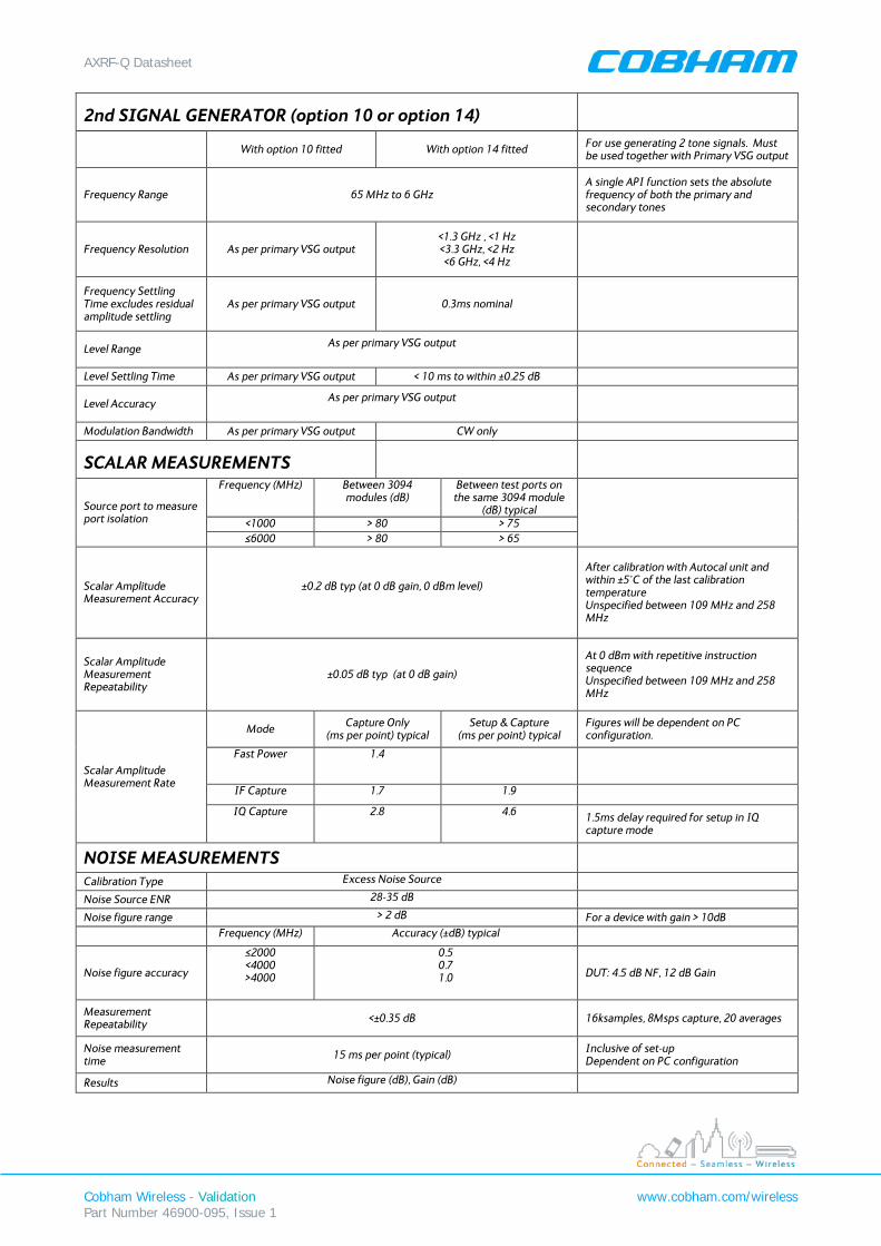
2nd SIGNAL GENERATOR (option 10 or option 14)
With option 10 fitted With option 14 fitted For use generating 2 tone signals. Must
be used together with Primary VSG output
Frequency Range 65 MHz to 6 GHz A single API function sets the absolute frequency of both the primary and secondary tones
Frequency Resolution As per primary VSG output <1.3 GHz , <1 Hz <3.3 GHz, <2 Hz <6 GHz, <4 Hz
Frequency Settling Time excludes residual amplitude settling
As per primary VSG output 0.3ms nominal
Level Range As per primary VSG output
Level Settling Time As per primary VSG output < 10 ms to within ±0.25 dB
Level Accuracy As per primary VSG output
Modulation Bandwidth As per primary VSG output CW only
SCALAR MEASUREMENTS
Source port to measure port isolation
Frequency (MHz) Between 3094 modules (dB)
Between test ports on the same 3094 module
(dB) typical
<1000 > 80 > 75 ≤6000 > 80 > 65
Scalar Amplitude Measurement Accuracy
±0.2 dB typ (at 0 dB gain, 0 dBm level)
After calibration with Autocal unit and within ±5°C of the last calibration temperature Unspecified between 109 MHz and 258 MHz
Scalar Amplitude Measurement Repeatability
±0.05 dB typ (at 0 dB gain)
At 0 dBm with repetitive instruction sequence Unspecified between 109 MHz and 258 MHz
Scalar Amplitude Measurement Rate
Mode Capture Only (ms per point) typical
Setup & Capture (ms per point) typical
Figures will be dependent on PC configuration.
Fast Power 1.4
IF Capture 1.7 1.9 IQ Capture 2.8 4.6 1.5ms delay required for setup in IQ
capture mode
NOISE MEASUREMENTS
Calibration Type Excess Noise Source
Noise Source ENR 28-35 dB
Noise figure range > 2 dB For a device with gain > 10dB
Frequency (MHz) Accuracy (±dB) typical
Noise figure accuracy
≤2000 <4000 >4000
0.5 0.7 1.0 DUT: 4.5 dB NF, 12 dB Gain
Measurement Repeatability <±0.35 dB 16ksamples, 8Msps capture, 20 averages
Noise measurement time 15 ms per point (typical) Inclusive of set-up
Dependent on PC configuration
Results Noise figure (dB), Gain (dB)
AXRF-Q Datasheet
Cobham Wireless - Validation Part Number 46900-095, Issue 1
www.cobham.com/wireless
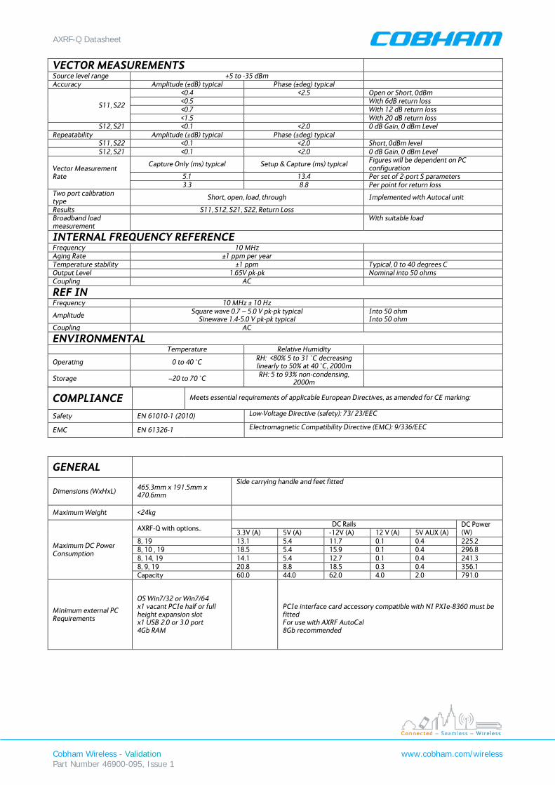
VECTOR MEASUREMENTS Source level range +5 to -35 dBm Accuracy Amplitude (±dB) typical Phase (±deg) typical
S11, S22
<0.4 <2.5 Open or Short, 0dBm <0.5 With 6dB return loss <0.7 With 12 dB return loss <1.5 With 20 dB return loss
S12, S21 <0.1 <2.0 0 dB Gain, 0 dBm Level Repeatability Amplitude (±dB) typical Phase (±deg) typical
S11, S22 <0.1 <2.0 Short, 0dBm level S12, S21 <0.1 <2.0 0 dB Gain, 0 dBm Level
Vector Measurement Rate
Capture Only (ms) typical Setup & Capture (ms) typical Figures will be dependent on PC configuration
5.1 13.4 Per set of 2-port S parameters 3.3 8.8 Per point for return loss
Two port calibration type Short, open, load, through Implemented with Autocal unit
Results S11, S12, S21, S22, Return Loss Broadband load measurement
With suitable load
INTERNAL FREQUENCY REFERENCE Frequency 10 MHz Aging Rate ±1 ppm per year Temperature stability ±1 ppm Typical, 0 to 40 degrees C Output Level 1.65V pk-pk Nominal into 50 ohms Coupling AC
REF IN Frequency 10 MHz ± 10 Hz
Amplitude Square wave 0.7 – 5.0 V pk-pk typical Sinewave 1.4-5.0 V pk-pk typical
Into 50 ohm Into 50 ohm
Coupling AC
ENVIRONMENTAL Temperature Relative Humidity
Operating 0 to 40 °C RH: <80% 5 to 31 °C decreasing linearly to 50% at 40 °C, 2000m
Storage −20 to 70 °C RH: 5 to 93% non-condensing, 2000m
COMPLIANCE
Meets essential requirements of applicable European Directives, as amended for CE marking:
Safety EN 61010-1 (2010) Low-Voltage Directive (safety): 73/ 23/EEC
EMC EN 61326-1 Electromagnetic Compatibility Directive (EMC): 9/336/EEC
GENERAL
Dimensions (WxHxL) 465.3mm x 191.5mm x 470.6mm
Side carrying handle and feet fitted
Maximum Weight <24kg
Maximum DC Power Consumption
AXRF-Q with options.. DC Rails DC Power (W) 3.3V (A) 5V (A) -12V (A) 12 V (A) 5V AUX (A)
8, 19 13.1 5.4 11.7 0.1 0.4 225.2 8, 10 , 19 18.5 5.4 15.9 0.1 0.4 296.8 8, 14, 19 14.1 5.4 12.7 0.1 0.4 241.3 8, 9, 19 20.8 8.8 18.5 0.3 0.4 356.1 Capacity 60.0 44.0 62.0 4.0 2.0 791.0
Minimum external PC Requirements
OS Win7/32 or Win7/64 x1 vacant PCIe half or full height expansion slot x1 USB 2.0 or 3.0 port 4Gb RAM
PCIe interface card accessory compatible with NI PXIe-8360 must be fitted For use with AXRF AutoCal 8Gb recommended
AXRF-Q Datasheet
Cobham Wireless - Validation Part Number 46900-095, Issue 1
www.cobham.com/wireless
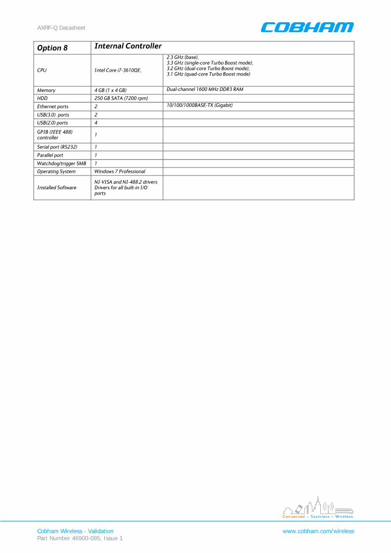
Option 8 Internal Controller
CPU Intel Core i7-3610QE,
2.3 GHz (base), 3.3 GHz (single-core Turbo Boost mode), 3.2 GHz (dual-core Turbo Boost mode), 3.1 GHz (quad-core Turbo Boost mode)
Memory 4 GB (1 x 4 GB) Dual-channel 1600 MHz DDR3 RAM
HDD 250 GB SATA (7200 rpm)
Ethernet ports 2 10/100/1000BASE-TX (Gigabit)
USB(3.0) ports 2
USB(2.0) ports 4
GPIB (IEEE 488) controller 1
Serial port (RS232) 1
Parallel port 1
Watchdog/trigger SMB 1
Operating System Windows 7 Professional
Installed Software NI-VISA and NI-488.2 drivers Drivers for all built-in I/O ports
AXRF-Q Datasheet
Cobham Wireless - Validation Part Number 46900-095, Issue 1
www.cobham.com/wireless
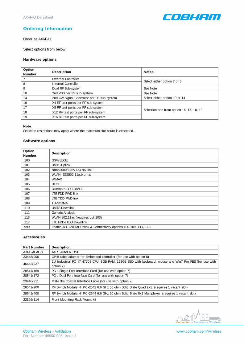
Ordering Information Order as AXRF-Q Select options from below Hardware options Option Number
Description Notes
7 External Controller Select either option 7 or 8
8 Internal Controller 9 Dual RF Sub-system See Note 10 2nd VSG per RF sub-system See Note
Select either option 10 or 14 14 2nd CW Signal Generator per RF sub-system 16 X4 RF test ports per RF sub-system
Selection one from option 16, 17, 18, 19 17 X8 RF test ports per RF sub-system 18 X12 RF test ports per RF sub-system 19 X16 RF test ports per RF sub-system Note Selection restrictions may apply where the maximum slot count is exceeded. Software options Option Number
Description
100 GSM/EDGE 101 UMTS Uplink 102 cdma2000/1xEV-DO rev link 103 WLAN IEEE802.11a,b,g,n,p 104 WiMAX 105 DECT 106 Bluetooth BR/EDR/LE 107 LTE FDD FWD link 108 LTE TDD FWD link 109 TD-SCDMA 110 UMTS Downlink 111 Generic Analysis 113 WLAN 802.11ac (requires opt 103) 117 LTE FDD&TDD Downlink 999 Enable ALL Cellular Uplink & Connectivity options 100-109, 111, 113
Accessories Part Number Description AXRF-ACAL-8 AXRF AutoCal Unit 23448/906 GPIB cable adapter for Embedded controller (for use with option 8)
46662/927 2U Industrial PC i7 4770S CPU, 8GB RAM, 128GB SSD with keyboard, mouse and Win7 Pro FES (for use with option 7)
28541/169 PCIe Single Port Interface Card (for use with option 7) 28541/172 PCIe Dual Port Interface Card (for use with option 7)
23448/911 MXIe 3m Coaxial Interface Cable (for use with option 7)
28541/200 RF Switch Module NI PXI-2542 6.6 GHz 50 ohm Solid State Quad 2x1 (requires 1 vacant slot)
28541/400 RF Switch Module NI PXI-2544 6.6 GHz 50 ohm Solid State 8x1 Multiplexer (requires 1 vacant slot)
22326/114 Front Mounting Rack Mount kit