ick foundation memory - access r · reg. mercantil de madrid, tomo 30.059, folio 205, sección 8ª,...
TRANSCRIPT

iCK Foundation
Analysis and Design
Work: iCK Foundation
Location: Description: Detail analysis and design of iCK patented foundation for Wind Turbine Towers Prop: Gestamp Hybrid Towers Date: 31/10/2012 File:
Author: Jorge Franco Rey Ingeniero de Caminos, Canales y Puertos Colegiado: 19.951

Avda. Monforte de Lemos 187 10B
28035 Madrid (Spain)
www.iconkrete.com
iConkrete, S.L., Avda. Monforte de Lemos 187 10B, 28035 Madrid. Reg. Mercantil de Madrid, Tomo 30.059, Folio 205, Sección 8ª, hoja M-541038. CIF: B86491131
M-2
1. ABSTRACT 4
2. SOFTWARE USED 7
3. AIMS AND DIFFERENT LEVEL ANALYSIS 8
3.1. LEVEL 1 ANALYSIS 8 3.2. LEVEL 2 ANALYSIS 11 3.3. LEVEL 3 ANALYSIS 12
4. DIFFERENT ANALYSIS LEVELS RESULT VERIFICATION 13
4.1. VERIFICATION A OF THE LEVEL 1 ANALYSIS MODEL 13 4.1.1. COMPARISON CHART 16 4.1.2. APPLICATION TO OCTAGONAL SHAPE FOUNDATIONS 17 4.2. VERIFICATION B OF THE LEVEL 1 ANALYSIS MODEL 18 4.2.1. COMPARISON CHART 21 4.3. VERIFICATION C 22 4.4. VERIFICATION D 23 4.4.1. COMPARISON CHART 27
5. WIND TURBINE TOWER CONSIDERED 28
6. DESIGN CODE 28
7. GEOTECHNICAL DESIGN 29
7.1. SKIN FRICTION 29 7.2. ADHESION 30 7.3. SLOPE STABILITY DURING EXCAVATION 31
8. STRUCTURAL DESIGN 32
8.1. CONCRETE COVER 32 8.2. INTERNAL FORCES 32 8.2.1. BEAMS 32 8.2.2. CENTRAL RING AND TOP SLAB 33
9. REFERENCES 34

Avda. Monforte de Lemos 187 10B
28035 Madrid (Spain)
www.iconkrete.com
iConkrete, S.L., Avda. Monforte de Lemos 187 10B, 28035 Madrid. Reg. Mercantil de Madrid, Tomo 30.059, Folio 205, Sección 8ª, hoja M-541038. CIF: B86491131
M-3
10. ANNEX 1: WIND TURBINE LOADS 1
11. ANNEX 2: LEVEL 1 CALCULATIONS 1
12. ANNEX 3: LEVEL 2 CALCULATIONS 1
12.1. TOP SLAB DESIGN 2 12.1.1. GENERAL MODEL DATA 2 12.1.2. SLAB FLEXURAL DESIGN 5 12.1.3. SLAB SHEAR DESIGN 42 12.1.4. SLAB SUSPENSION REINFORCEMENT 43 12.2. CENTRAL RING DESIGN 46 12.2.1. OUTER HORIZONTAL REINFORCEMENT 46 12.2.2. OUTER VERTICAL REINFORCEMENT 61 12.2.3. INNER HORIZONTAL REINFORCEMENT 67 12.2.4. INNER VERTICAL REINFORCEMENT 73
13. ANNEX 4: LEVEL 3 CALCULATIONS 1
13.1. INTRODUCTION 2 13.2. MODEL 03AAB: EXTREME LOADS (NORMAL SITUATION) 3 13.2.1. MATERIALS 3 13.2.2. LOADS 4 13.2.3. CONSTRUCTION STAGES 5 13.2.4. FINITE ELEMENT MESH 5 13.2.5. RESULTS 6 13.3. MODEL 03AAB: OVERTURNING ANALYSIS 14 13.3.1. MATERIALS 15 13.3.2. LOADS 16 13.3.3. CONSTRUCTION STAGES 17 13.3.4. FINITE ELEMENT MESH 17 13.3.5. RESULTS 18
14. FIGURES INDEX 23

Avda. Monforte de Lemos 187 10B
28035 Madrid (Spain)
www.iconkrete.com
iConkrete, S.L., Avda. Monforte de Lemos 187 10B, 28035 Madrid. Reg. Mercantil de Madrid, Tomo 30.059, Folio 205, Sección 8ª, hoja M-541038. CIF: B86491131
M-4
1. Abstract
The iCK foundation presents four principal elements:
a) A top slab whose function is to achieve a more uniform distribution of pressure on the ground
b) A central reinforced ring
c) Several radial reinforced beams or stiffening ribs that forms a composite section with the top slab.
d) Pedestal
Fig. 1: Geometry of the iCK foundation

Avda. Monforte de Lemos 187 10B
28035 Madrid (Spain)
www.iconkrete.com
iConkrete, S.L., Avda. Monforte de Lemos 187 10B, 28035 Madrid. Reg. Mercantil de Madrid, Tomo 30.059, Folio 205, Sección 8ª, hoja M-541038. CIF: B86491131
M-5
Fig. 2: Bottom view of the foundation
¿Why this design? The design of the iCK foundation is different from other existing foundations in which the ribs are arranged on the top of the slab. Our goal is developing a better structural performance with a T section that provides more efficiency and ductility. This is because the bending stresses to which it is subjected in the foundation act precisely the bottom-up direction, so that the traction is placed on the bottom and the compressions in the top.
Fig. 3: Beam bending moment

Avda. Monforte de Lemos 187 10B
28035 Madrid (Spain)
www.iconkrete.com
iConkrete, S.L., Avda. Monforte de Lemos 187 10B, 28035 Madrid. Reg. Mercantil de Madrid, Tomo 30.059, Folio 205, Sección 8ª, hoja M-541038. CIF: B86491131
M-6
With the configuration of the iCK foundation you have a T-section, highly efficient, which compressions are distributed across the top of the T head, getting a higher inner lever arm and a significant improvement in the ductility by reducing the relative depth of the neutral axis. In the pictures below compares the flexural strength between the iCK foundation and a foundation with stiffening ribs placed in top position:
Fig. 4: iCK foundation. Ultimate Bending Moment = 33000 KNm, x/d=0,12
Fig. 5: Conventional ribbed foundation. Ultimate Bending Moment = 29800 KNm, x/d = 0,38
As can be seen, with the iCK foundation design, at equal volume amount of concrete reinforcement, gives a flexural strength 10% higher and a depth relative neutral fiber considerably lower (0.12 versus 0.38) , which allows a higher ductility, a higher resistant reserve and an improved fatigue behavior for the concrete. The performance of the iCK foundation has been tested with an advanced FEM geothecnical calculation with Midas GTS software that takes into account the construction stages, the different properties of the soil and the interaction between the soil and the foundation.

Avda. Monforte de Lemos 187 10B
28035 Madrid (Spain)
www.iconkrete.com
iConkrete, S.L., Avda. Monforte de Lemos 187 10B, 28035 Madrid. Reg. Mercantil de Madrid, Tomo 30.059, Folio 205, Sección 8ª, hoja M-541038. CIF: B86491131
M-7
2. Software used
- Propietary software developed under licensed Microsoft Excel v.2010
- Midas Gen v 2012, by Midas Information Technology, license nº U001-04379
- Midas GTS v 2012 by Midas Information Technology, license nº U001-05346
- Fagus 6 by Cubus AG, license nº BN-4096-01

Avda. Monforte de Lemos 187 10B
28035 Madrid (Spain)
www.iconkrete.com
iConkrete, S.L., Avda. Monforte de Lemos 187 10B, 28035 Madrid. Reg. Mercantil de Madrid, Tomo 30.059, Folio 205, Sección 8ª, hoja M-541038. CIF: B86491131
M-8
3. Aims and different level analysis
The main objective in this document is to study and analyze the patented iCK Foundation, presenting all the results of calculation and design, both from a geotechnical and structural point of view. Three levels of complexity are used in the study of the iCK foundation:
3.1. Level 1 analysis
Classic treatment. We have implemented an application to obtain the soil pressure distribution between a circular foundation and further obtain the overturning a sliding security factor and the effective uniform soil pressure in order to calculate the beam (ribs) internal forces.
Fig. 6: Soil pressures on a circular foundation. See [1]
Fig. 7: Graph to calculate circular foundations. See [1]
The following implicit expression is resolved numerically through the Microsoft Excel Solver add-in.
With the solution, we have the neutral axis depth and we can obtain the soil pressure distribution under the foundation. We know that the iCK foundation is not a perfect circular slab with a smooth surface in contact with the soil, as other common foundations for wind turbines, but at this level study we think is sufficiently approximate. With the analysis of levels 2 and 3 we will check the veracity of this statement.
Avda. Monforte de Lemos 187 10B
28035 Madrid (Spain)
www.iconkrete.com
iConkrete, S.L., Avda. Monforte de Lemos 187 10B, 28035 Madrid. Reg. Mercantil de Madrid, Tomo 30.059, Folio 205, Sección 8ª, hoja M-541038. CIF: B86491131
M-9
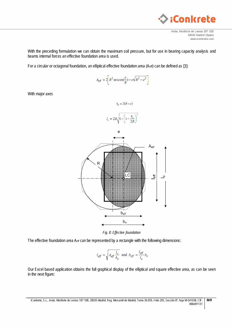
With the preceding formulation we can obtain the maximum soil pressure, but for use in bearing capacity analysis and beams internal forces an effective foundation area is used. For a circular or octagonal foundation, an elliptical effective foundation area (Aeff) can be defined as [3]:
With major axes
Fig. 8: Effective foundation
The effective foundation area Aeff can be represented by a rectangle with the following dimensions:
Our Excel based application obtains the full graphical display of the elliptical and square effective area, as can be seen in the next figure:

Avda. Monforte de Lemos 187 10B
28035 Madrid (Spain)
www.iconkrete.com
iConkrete, S.L., Avda. Monforte de Lemos 187 10B, 28035 Madrid. Reg. Mercantil de Madrid, Tomo 30.059, Folio 205, Sección 8ª, hoja M-541038. CIF: B86491131
M-10
Fig. 9: Elliptic and rectangular effective areas
Avda. Monforte de Lemos 187 10B
28035 Madrid (Spain)
www.iconkrete.com
iConkrete, S.L., Avda. Monforte de Lemos 187 10B, 28035 Madrid. Reg. Mercantil de Madrid, Tomo 30.059, Folio 205, Sección 8ª, hoja M-541038. CIF: B86491131
M-11
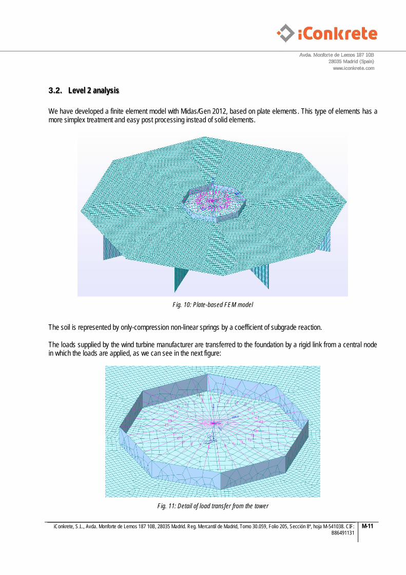
3.2. Level 2 analysis
We have developed a finite element model with Midas/Gen 2012, based on plate elements. This type of elements has a more simplex treatment and easy post processing instead of solid elements.
Fig. 10: Plate-based FEM model
The soil is represented by only-compression non-linear springs by a coefficient of subgrade reaction. The loads supplied by the wind turbine manufacturer are transferred to the foundation by a rigid link from a central node in which the loads are applied, as we can see in the next figure:
Fig. 11: Detail of load transfer from the tower

Avda. Monforte de Lemos 187 10B
28035 Madrid (Spain)
www.iconkrete.com
iConkrete, S.L., Avda. Monforte de Lemos 187 10B, 28035 Madrid. Reg. Mercantil de Madrid, Tomo 30.059, Folio 205, Sección 8ª, hoja M-541038. CIF: B86491131
M-12
3.3. Level 3 analysis
In this level, we have developed an advanced 3D geotechnical finite element model with the Midas GTS program. In this model we define the real 3D geometry of the soil and the different construction stages (excavation, concrete pouring,
Fig. 12: Advanced finite element model
Avda. Monforte de Lemos 187 10B
28035 Madrid (Spain)
www.iconkrete.com
iConkrete, S.L., Avda. Monforte de Lemos 187 10B, 28035 Madrid. Reg. Mercantil de Madrid, Tomo 30.059, Folio 205, Sección 8ª, hoja M-541038. CIF: B86491131
M-13
4. Different analysis levels result verification
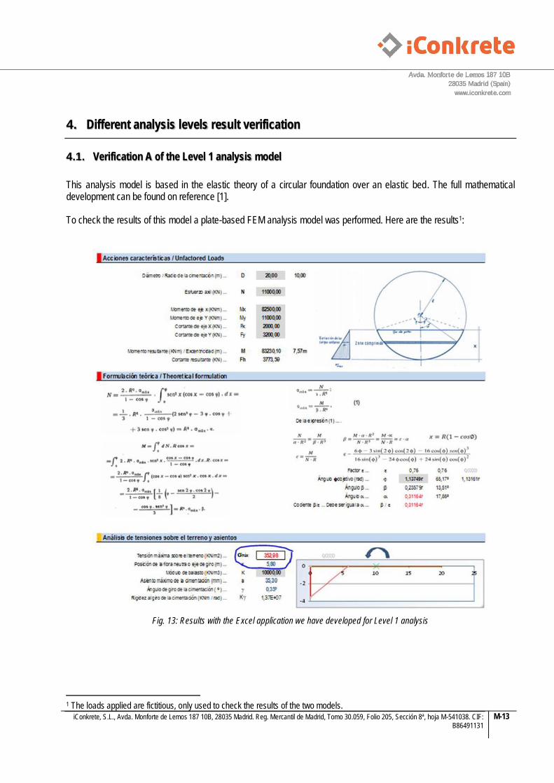
4.1. Verification A of the Level 1 analysis model
This analysis model is based in the elastic theory of a circular foundation over an elastic bed. The full mathematical development can be found on reference [1]. To check the results of this model a plate-based FEM analysis model was performed. Here are the results1:
Fig. 13: Results with the Excel application we have developed for Level 1 analysis
1 The loads applied are fictitious, only used to check the results of the two models.

Avda. Monforte de Lemos 187 10B
28035 Madrid (Spain)
www.iconkrete.com
iConkrete, S.L., Avda. Monforte de Lemos 187 10B, 28035 Madrid. Reg. Mercantil de Madrid, Tomo 30.059, Folio 205, Sección 8ª, hoja M-541038. CIF: B86491131
M-14
Fig. 14: Circular plate resting on elastic bed with the same modulus of subgrade reaction
Fig. 15: Vertical displacements of the foundation

Avda. Monforte de Lemos 187 10B
28035 Madrid (Spain)
www.iconkrete.com
iConkrete, S.L., Avda. Monforte de Lemos 187 10B, 28035 Madrid. Reg. Mercantil de Madrid, Tomo 30.059, Folio 205, Sección 8ª, hoja M-541038. CIF: B86491131
M-15
Fig. 16: Detail of the vertical displacements
Fig. 17: Neutral axis determination in the FEM model

Avda. Monforte de Lemos 187 10B
28035 Madrid (Spain)
www.iconkrete.com
iConkrete, S.L., Avda. Monforte de Lemos 187 10B, 28035 Madrid. Reg. Mercantil de Madrid, Tomo 30.059, Folio 205, Sección 8ª, hoja M-541038. CIF: B86491131
M-16
Fig. 18: Spring reactions that show us the soil pressure distribution
4.1.1. Comparison chart
Max. soil pressure (KN/m2)
Max. Vertical displacement (mm)
Neutral axis distance (m)
Excel Level 1 model 352,98 35,30 5,80
Midas Gen FEM plate-based model 358,32 35,83 6,00
% Dif. 1,51% 1,50% 3,45 %

Avda. Monforte de Lemos 187 10B
28035 Madrid (Spain)
www.iconkrete.com
iConkrete, S.L., Avda. Monforte de Lemos 187 10B, 28035 Madrid. Reg. Mercantil de Madrid, Tomo 30.059, Folio 205, Sección 8ª, hoja M-541038. CIF: B86491131
M-17
4.1.2. Application to octagonal shape foundations
In order to simplify the rebar of the top slab, we used a circumscribed octagonal shape. We think the differences are small and the Level 1 application to determine soil pressures is sufficiently approximate.
Fig. 19: Circumscribed octagonal shape top slab

Avda. Monforte de Lemos 187 10B
28035 Madrid (Spain)
www.iconkrete.com
iConkrete, S.L., Avda. Monforte de Lemos 187 10B, 28035 Madrid. Reg. Mercantil de Madrid, Tomo 30.059, Folio 205, Sección 8ª, hoja M-541038. CIF: B86491131
M-18
4.2. Verification B of the Level 1 analysis model
In order to check the beam internal forces obtained with the level 1 analysis model, we have develop a simple model based on beams resting on an multilinear point spring support.
Fig. 20: Simple bar finite element model

Avda. Monforte de Lemos 187 10B
28035 Madrid (Spain)
www.iconkrete.com
iConkrete, S.L., Avda. Monforte de Lemos 187 10B, 28035 Madrid. Reg. Mercantil de Madrid, Tomo 30.059, Folio 205, Sección 8ª, hoja M-541038. CIF: B86491131
M-19
Fig. 21: Loads applied to the model
We have limited the maximum soil pressure on the beam end using a multi-linear spring with this hysteresis curve:
Fig. 22: Multi-linear point spring support
Fig. 23: Multi-linear point spring support definition
The limitation of 350 KN respond to a maxium soil pressure equal to 350 KN / (1,20m·0,588m) = 496 KN/m2 0,588 m is the separation between nodes of the model and 1,20 m is the beam width.
Avda. Monforte de Lemos 187 10B
28035 Madrid (Spain)
www.iconkrete.com
iConkrete, S.L., Avda. Monforte de Lemos 187 10B, 28035 Madrid. Reg. Mercantil de Madrid, Tomo 30.059, Folio 205, Sección 8ª, hoja M-541038. CIF: B86491131
M-20
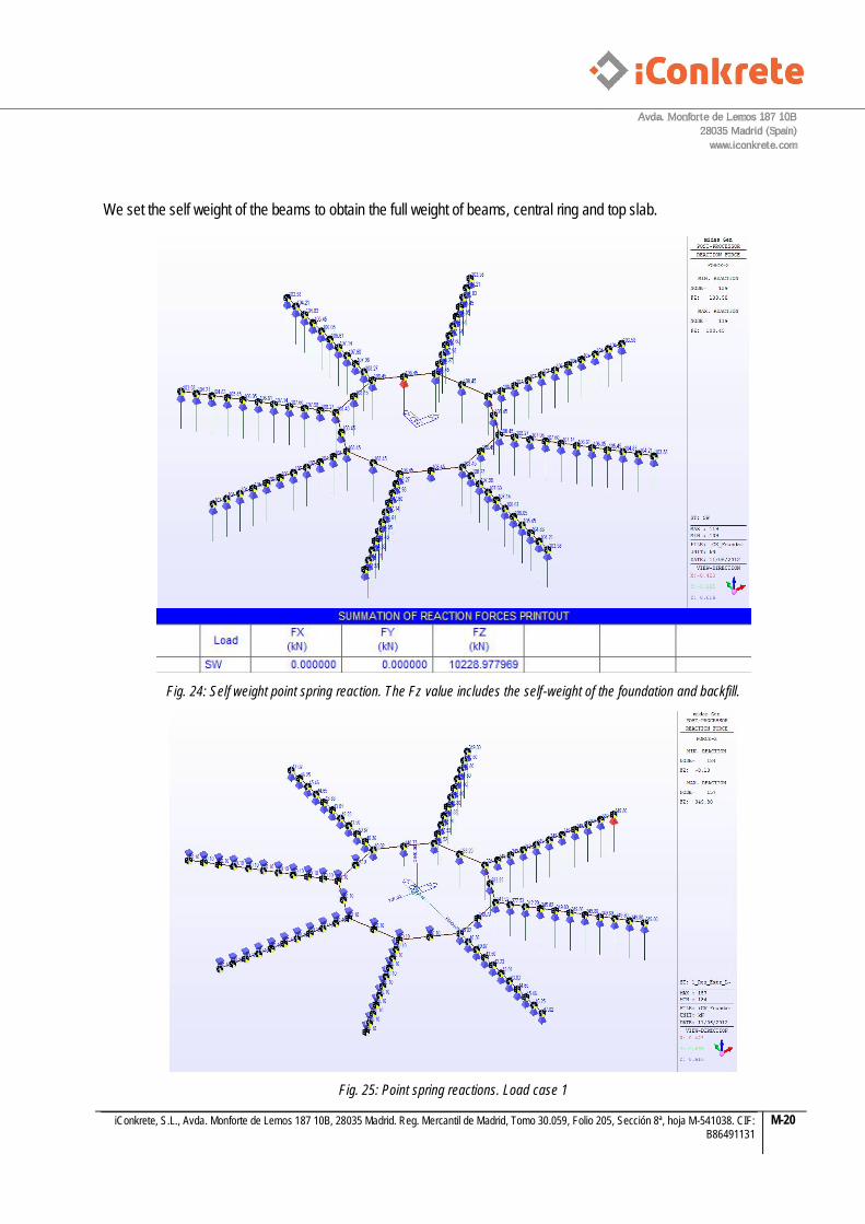
We set the self weight of the beams to obtain the full weight of beams, central ring and top slab.
Fig. 24: Self weight point spring reaction. The Fz value includes the self-weight of the foundation and backfill.
Fig. 25: Point spring reactions. Load case 1

Avda. Monforte de Lemos 187 10B
28035 Madrid (Spain)
www.iconkrete.com
iConkrete, S.L., Avda. Monforte de Lemos 187 10B, 28035 Madrid. Reg. Mercantil de Madrid, Tomo 30.059, Folio 205, Sección 8ª, hoja M-541038. CIF: B86491131
M-21
Fig. 26: Bending moments load case 1
4.2.1. Comparison chart
Factored bottom bending
moment Load Case 1
(KNm)
Factored top bending moment
Load Case 1 (KNm)
Excel Level 1 model 12134 -3667
Midas Gen bar model 8647·1,50 = 12970 -2683,5·1,50 = -4025
% Dif. 6,8% 9,7%
The bar model is a simplification in which all the forces are taken by the bars. In reality, the top slab takes a part of the forces, downloading the beams.
Avda. Monforte de Lemos 187 10B
28035 Madrid (Spain)
www.iconkrete.com
iConkrete, S.L., Avda. Monforte de Lemos 187 10B, 28035 Madrid. Reg. Mercantil de Madrid, Tomo 30.059, Folio 205, Sección 8ª, hoja M-541038. CIF: B86491131
M-22
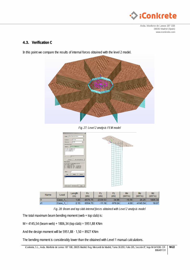
4.3. Verification C
In this point we compare the results of internal forces obtained with the level 2 model.
Fig. 27: Level 2 analysis FEM model
Fig. 28: Beam and top slab internal forces obtained with Level 2 analysis model
The total maximum beam bending moment (web + top slab) is: M = 4145,54 (beam web) + 1806,34 (top slab) = 5951,88 KNm And the design moment will be 5951,88 · 1,50 = 8927 KNm The bending moment is considerably lower than the obtained with Level 1 manual calculations.
Avda. Monforte de Lemos 187 10B
28035 Madrid (Spain)
www.iconkrete.com
iConkrete, S.L., Avda. Monforte de Lemos 187 10B, 28035 Madrid. Reg. Mercantil de Madrid, Tomo 30.059, Folio 205, Sección 8ª, hoja M-541038. CIF: B86491131
M-23
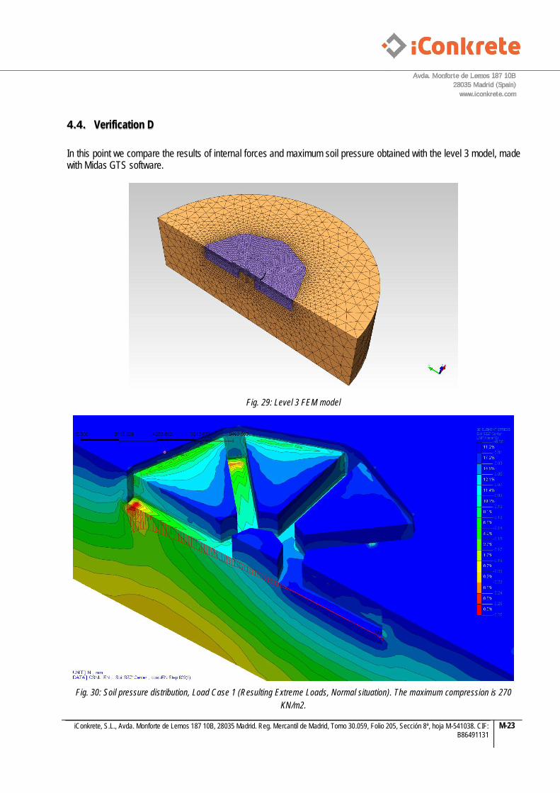
4.4. Verification D
In this point we compare the results of internal forces and maximum soil pressure obtained with the level 3 model, made with Midas GTS software.
Fig. 29: Level 3 FEM model
Fig. 30: Soil pressure distribution, Load Case 1 (Resulting Extreme Loads, Normal situation). The maximum compression is 270
KN/m2.

Avda. Monforte de Lemos 187 10B
28035 Madrid (Spain)
www.iconkrete.com
iConkrete, S.L., Avda. Monforte de Lemos 187 10B, 28035 Madrid. Reg. Mercantil de Madrid, Tomo 30.059, Folio 205, Sección 8ª, hoja M-541038. CIF: B86491131
M-24
Fig. 31: Fig. 32: Vertical soil pressure under beam
Avda. Monforte de Lemos 187 10B
28035 Madrid (Spain)
www.iconkrete.com
iConkrete, S.L., Avda. Monforte de Lemos 187 10B, 28035 Madrid. Reg. Mercantil de Madrid, Tomo 30.059, Folio 205, Sección 8ª, hoja M-541038. CIF: B86491131
M-25
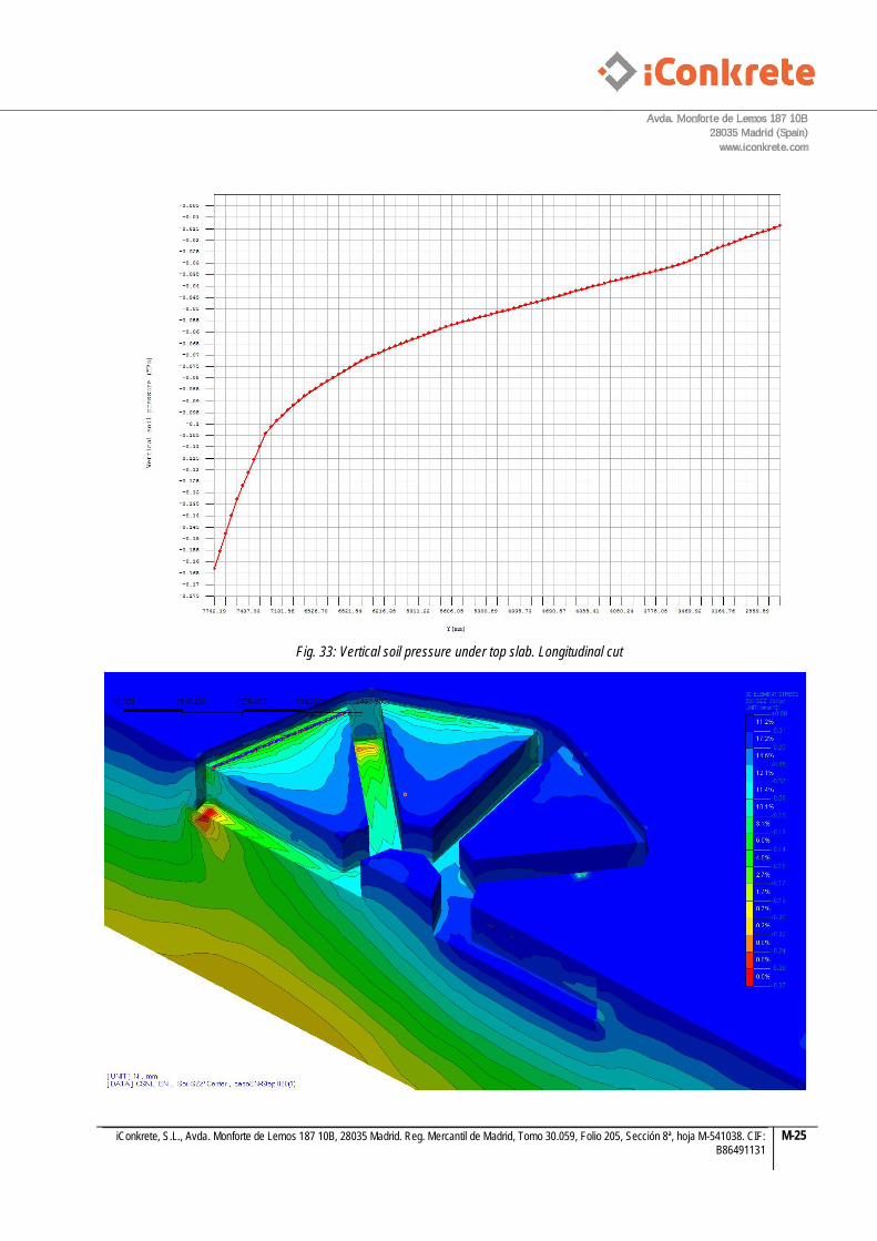
Fig. 33: Vertical soil pressure under top slab. Longitudinal cut

Avda. Monforte de Lemos 187 10B
28035 Madrid (Spain)
www.iconkrete.com
iConkrete, S.L., Avda. Monforte de Lemos 187 10B, 28035 Madrid. Reg. Mercantil de Madrid, Tomo 30.059, Folio 205, Sección 8ª, hoja M-541038. CIF: B86491131
M-26
Fig. 34: Vertical soil pressure under top slab. Transversal cut
Fig. 35: Beam forces integration. The unfactored bending moment is My = 3610 KNm · 2 = 7220 KNm

Avda. Monforte de Lemos 187 10B
28035 Madrid (Spain)
www.iconkrete.com
iConkrete, S.L., Avda. Monforte de Lemos 187 10B, 28035 Madrid. Reg. Mercantil de Madrid, Tomo 30.059, Folio 205, Sección 8ª, hoja M-541038. CIF: B86491131
M-27
4.4.1. Comparison chart
Factored bottom bending
moment Load Case 1
(KNm)
Maximum soil pressure Load Case 1
(KN/m2)
Excel Level 1 model 12134 183,30
Midas Gen bar model 8647·1,50 = 12970 Not obtained
Midas Gen plate model (Level 2) 5951,88 · 1,50 = 8927,82 162,69
Midas GTS 3D FEM model (Level 3) 7220 · 1,50 = 10830 Peak beam: 262 KN/m2 (*1)
Peak slab: 160 KN/m2 (*2) (*1) Peak soil pressure under beam. In the Fig. 48 can be seen that this is a peak stress and that rapidly decreases to a value of aprox. 160 KN/m2 (0,16 MPa). Under the slab (*2) the peak stress is aprox. 160 KN/m2. We can see that the results are similar. The forces obtained with the model of level 1 are the largest of comparison and will be used for beam design in this document. Therefore, the design of the iCK foundation with the downward ribs is functioning properly. Compared to a conventional foundation with the flat base it can be seen that there is a little stress concentration under the beam end that, in any case, has an acceptable value. Can also be seen the collaboration of the top slab in the distribution of loads over the soil.
Avda. Monforte de Lemos 187 10B
28035 Madrid (Spain)
www.iconkrete.com
iConkrete, S.L., Avda. Monforte de Lemos 187 10B, 28035 Madrid. Reg. Mercantil de Madrid, Tomo 30.059, Folio 205, Sección 8ª, hoja M-541038. CIF: B86491131
M-28
5. Wind Turbine Tower considered
All the calculations have been developed with the following Wind Turbine: VESTAS V100 1.8 MW Mk7.5 HH 80m IECS T-flange The foundation loads can be found in Annex 1. The foundation is designed with a steel tower, but is valid for a full concrete or a hybrid tower. Both full concrete and hybrid tower has the advantage of a major self-weight, which is a favourable effect for the foundation.
6. Design code
In this document the Eurocodes are used. own national appendix to the Eurocodes wich specifies values that should be used to fulfill the demands. In this document the recommended values are used. Also, in concordance with DIN 1054, Limit states of failure in the ground and soil pressure distribution are verified using Design Approach 2 in which the entire calculation is performed using characteristic values and the partial factors are introduced at the end, when the ultimate limit state condition is checked. The global ULS factor used to obtain the factored loads for the structural concrete design is 1,50.

Avda. Monforte de Lemos 187 10B
28035 Madrid (Spain)
www.iconkrete.com
iConkrete, S.L., Avda. Monforte de Lemos 187 10B, 28035 Madrid. Reg. Mercantil de Madrid, Tomo 30.059, Folio 205, Sección 8ª, hoja M-541038. CIF: B86491131
M-29
7. Geotechnical design
The geotechnical design has to consider several possible types of failure. The ones that are verified in this memory are:
: soil pressure verification.
: overturning and sliding security factor.
Settlements calculation The iCK foundation allows selectively taking into consideration the skin friction resistance and adhesion between the soil and the radial beams and the soil. This has been implemented as described below.
7.1. Skin friction
Fig. 36: Soil pressure over the radial beams and central ring
The unit frictional resistance is:
Koh is the at rest soil pressure coefficient:
o is the effective medium soil pressure over the lateral surface of beams and central ring:

Avda. Monforte de Lemos 187 10B
28035 Madrid (Spain)
www.iconkrete.com
iConkrete, S.L., Avda. Monforte de Lemos 187 10B, 28035 Madrid. Reg. Mercantil de Madrid, Tomo 30.059, Folio 205, Sección 8ª, hoja M-541038. CIF: B86491131
M-30
And
Fig. 37: Geometrical definition of the iCK foundation
7.2. Adhesion
The unit adhesion between soil and concrete is:
cu is the undrained shear strength.

Avda. Monforte de Lemos 187 10B
28035 Madrid (Spain)
www.iconkrete.com
iConkrete, S.L., Avda. Monforte de Lemos 187 10B, 28035 Madrid. Reg. Mercantil de Madrid, Tomo 30.059, Folio 205, Sección 8ª, hoja M-541038. CIF: B86491131
M-31
7.3. Slope stability during excavation
An important aspect is the stability of the slopes during excavation. In the advanced model 3D finite element the excavation has been considered as a construction stage, so the computation show us when it is necessary to excavate with a certain slope and / or arrange a shoring or formwork. Moreover, the mounting procedure of the iCK foundation is based in pre-assembling the reinforcement of beams and central ring for later introduction into previously excavated trenches. This procedure has the advantage of allowing the reinforcement assembling of several foundations before starting the excavation. Where required by ground conditions, on the preassembled reinforcement should be attached a formwork (like a geomesh, a wire mesh or pecafil system) that will prevent spillage during concreting. The geomesh or wire mesh has the advantage of allowing the passage of concrete so that it is in contact with the ground and can be counted on the frictional resistance and adhesion aforementioned.
Fig. 38: Example of pecafil formwork
Fig. 39: Example of geomesh
It is normal that the slopes are not perfectly vertical. In this situation the concrete volume will be greater and hence the weight of the foundation as well, which represents a favorable effect for the foundation. Also, in this case, the concrete surface will be greater and therefore the soil pressures will be smaller.
Avda. Monforte de Lemos 187 10B
28035 Madrid (Spain)
www.iconkrete.com
iConkrete, S.L., Avda. Monforte de Lemos 187 10B, 28035 Madrid. Reg. Mercantil de Madrid, Tomo 30.059, Folio 205, Sección 8ª, hoja M-541038. CIF: B86491131
M-32
8. Structural design
The reinforced concrete analysis is made with the Eurocode.
8.1. Concrete cover
Exposure class: XC2 Structural class: S4 Cover of concrete poured directly over the soil: 75 mm Cover of concrete poured over a regularization concrete bed: 40 mm
8.2. Internal forces
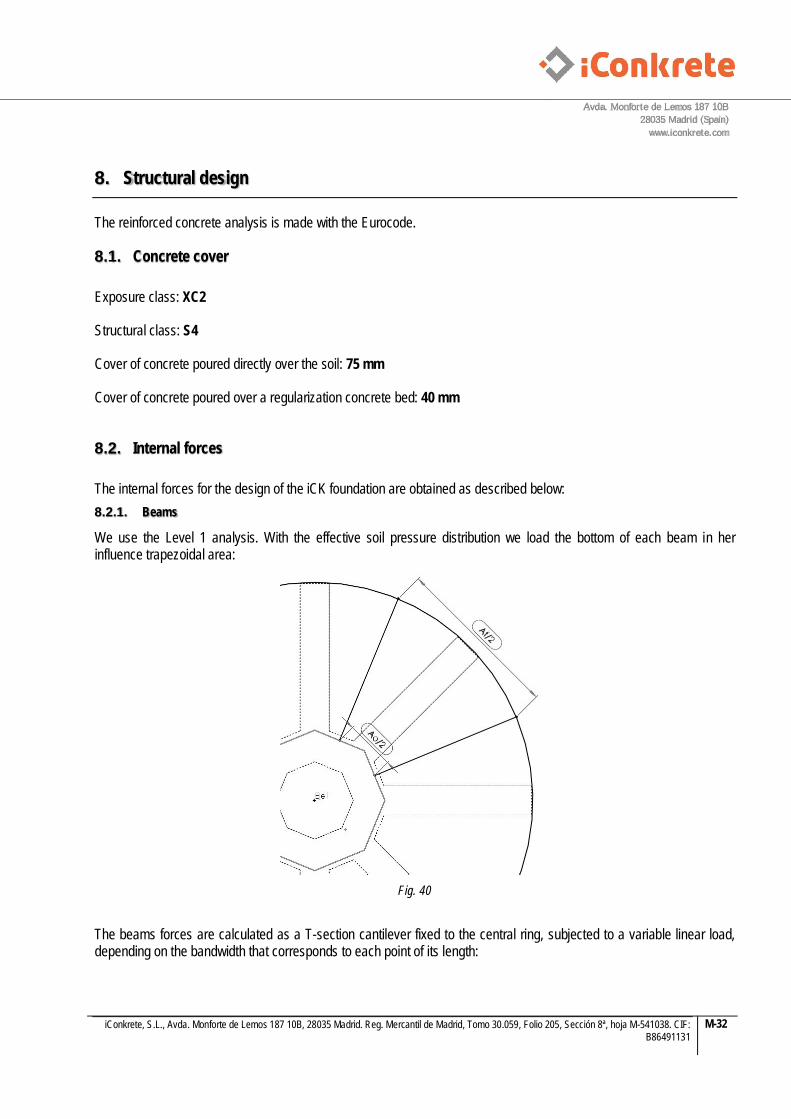
The internal forces for the design of the iCK foundation are obtained as described below: 8.2.1. Beams
We use the Level 1 analysis. With the effective soil pressure distribution we load the bottom of each beam in her influence trapezoidal area:
Fig. 40
The beams forces are calculated as a T-section cantilever fixed to the central ring, subjected to a variable linear load, depending on the bandwidth that corresponds to each point of its length:

Avda. Monforte de Lemos 187 10B
28035 Madrid (Spain)
www.iconkrete.com
iConkrete, S.L., Avda. Monforte de Lemos 187 10B, 28035 Madrid. Reg. Mercantil de Madrid, Tomo 30.059, Folio 205, Sección 8ª, hoja M-541038. CIF: B86491131
M-33
Fig. 41: Loading scheme of a radial beam
The design of the beams are made with Midas/Gen design capabilities.
8.2.2. Central ring and top slab
We use the Level 2 analysis. With the plate finite element model we obtain the internal forces of both components. The design of the central ring and top slab are made with Midas/Gen design capabilities.
En Madrid (Spain), 09 de Noviembre de 2012
Fdo.: Jorge Franco Rey Ingeniero de Caminos, Canales y Puertos, Col.19951 Director Técnico / Technical Manager

Avda. Monforte de Lemos 187 10B
28035 Madrid (Spain)
www.iconkrete.com
iConkrete, S.L., Avda. Monforte de Lemos 187 10B, 28035 Madrid. Reg. Mercantil de Madrid, Tomo 30.059, Folio 205, Sección 8ª, hoja M-541038. CIF: B86491131
M-34
9. References
[1] Cálculo de cimentaciones circulares. Antonio Angulo, Ingeniero de Caminos, Canales y Puertos. Revista de Obras Públicas, Junio de 1946. [2] Germanischer Lloyd (GL), Guideline for the Certification of Wind Turbines, Edition 2010 [3] Det Norske Veritas (DNV), Design of offshore wind turbine structures, Offshore standard DNV-OS-J101, September 2011 [4] Det Norske Veritas (DNV), Offshore concrete structures, Offshore standard DNV-OS-C502, October 2010 [5] H.Svensson, LUND University, Design of foundations for wind turbin [6] Guía de cimentaciones en obras de carretera. Gobierno de España, Ministerio de Fomento, Dirección Gral. de carreteras, 2009 [7] DIN-1054:2005-01 [8] European Committee for Standardization (ECS), Eurocode 7 Geotechnical design [9] European Committee for Standardization (ECS), Eurocode 2 Design of Concrete Structures Part 1.1: General rules and rules for buildings