idec sa1u photoelectric switches - clrwtr.com photoelectric switches types package quantity: 1...
TRANSCRIPT
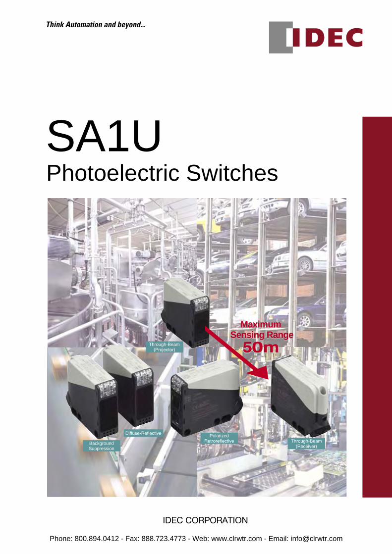
SA1UPhotoelectric Switches
Background Suppression
Diffuse-Reflective Polarized Retroreflective Through-Beam
(Receiver)
Through-Beam (Projector)
Maximum Sensing Range
Maximum Sensing Range
Phone: 800.894.0412 - Fax: 888.723.4773 - Web: www.clrwtr.com - Email: [email protected]
Long sensing range of 50m maximum (through-beam type)Universal voltage and DC power types available for worldwide usage SA1U Terminal
Block Type
Photoelectric Switches
IDEC’s original spring-up screwterminal block saves wiring time
Washdown IP67 Environment
Four Sensing Methods
Time Delay
Various Mounting Hole Layouts
Universal Voltage Power Supply
Ideal for use in a wet enviroment such as bottling and foodprocessing lines.
Four operation modes to choose from: one shot, ON delay,OFF delay, and normal modes. Time ranges can be set from 0.1 to 5 seconds.
Universal voltage types operate on 24 to 240V AC and 12 to 240V DC. DC power types operate on 12 to 24V DC.
Mounting hole centers are selectable from 40, 50 to 55 mm.
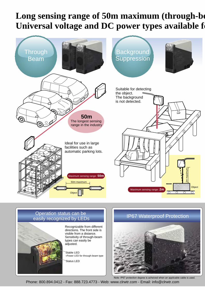
Long distance detection. Offers sensing range of up to 50m.
Sensing range up to 2m. Not affected by background.
Sensing range up to 7m. Easily detects mirrored surfaces.
Sensing range up to 1m. Detects objects that reflect light,even transparent objects.
Background suppresion
Polarized-retroreflective
Spring-up screw terminal blockenables easy wiring. Save up to65% wiring time comparedto competitor products(IDEC research).
IDEC’s unique spring-up screw terminal block∗ is used.∗The screw is normally in the lifted position, ready for wiring. No need to loosen or remove screws, improving work efficiency. Screws are held captive.
Spring-Up Screw Terminal BlockIP67 Waterproof Protection Easy WiringOperation status can be
easily recognized by LEDsRecognizable from different directions. The front side is visible from a distance. Sensitivity of through-beam types can easily be adjusted.
Close Mounting (except through-beam)Interference prevention enables close mountingof two SA1U photoelectric switches in limited spaces.
Diffuse-reflective
Through-beam
Suitable for detecting the object. The backgroundis not detected.
Ideal for use in largefacilities such as automatic parking lots.
PolarizedRetroreflective
ThroughBeam
BackgroundSuppression
DiffuseReflective
Easily detects objectsthat absorb light and mirror surface objects
Detects objects that reflect light, even transparent objects.
Maximum sensing range: 50m
Maximum sensing range: 2m
Maximum sensing range: 1m
Maximum sensing range: 7m
50mThe longest sensing range in the industry
50m maximum1m maximum
7m maximum
2m m
axim
um
Object
Object
Object
Object
Reflector
Stable LED*Power LED for through-beam type
Status LED
Note: IP67 protection degree is acheived when an applicable cable is used.
Phone: 800.894.0412 - Fax: 888.723.4773 - Web: www.clrwtr.com - Email: [email protected]

Long sensing range of 50m maximum (through-beam type)Universal voltage and DC power types available for worldwide usage SA1U Terminal
Block Type
Photoelectric Switches
IDEC’s original spring-up screw terminal block saves wiring time
Washdown IP67 Environment
Four Sensing Methods
Time Delay
Various Mounting Hole Layouts
Universal Voltage Power Supply
Ideal for use in a wet enviroment such as bottling and foodprocessing lines.
Four operation modes to choose from: one shot, ON delay,OFF delay, and normal modes. Time ranges can be set from 0.1 to 5 seconds.
Universal voltage types operate on 24 to 240V AC and 12 to 240V DC. DC power types operate on 12 to 24V DC.
Mounting hole centers are selectable from 40, 50 to 55 mm.
Long distance detection. Offers sensing range of up to 50m.
Sensing range up to 2m. Not affected by background.
Sensing range up to 7m. Easily detects mirrored surfaces.
Sensing range up to 1m. Detects objects that reflect light,even transparent objects.
Background suppresion
Polarized-retroreflective
Spring-up screw terminal blockenables easy wiring. Save up to 65% wiring time compared to competitor products (IDEC research).
IDEC’s unique spring-up screw terminal block∗ is used.∗The screw is normally in the lifted position, ready for wiring. No need to loosen or remove screws, improving work efficiency. Screws are held captive.
Spring-Up Screw Terminal BlockIP67 Waterproof Protection Easy WiringOperation status can be easily recognized by LEDs
Recognizable from differentdirections. The front side is visible from a distance.Sensitivity of through-beamtypes can easily be adjusted.
Close Mounting (except through-beam)Interference prevention enables close mountingof two SA1U photoelectric switches in limited spaces.
Diffuse-reflective
Through-beam
Suitable for detecting the object. The backgroundis not detected.
Ideal for use in largefacilities such as automatic parking lots.
PolarizedRetroreflective
ThroughBeam
BackgroundSuppression
DiffuseReflective
Easily detects objects that absorb light and mirror surface objects
Detects objects that reflect light, even transparent objects.
Maximum sensing range: 50m
Maximum sensing range: 2m
Maximum sensing range: 1m
Maximum sensing range: 7m
50mThe longest sensing range in the industry
50m maximum1m maximum
7m maximum
2m m
axim
um
Object
Object
Object
Object
Reflector
Phone: 800.894.0412 - Fax: 888.723.4773 - Web: www.clrwtr.com - Email: [email protected]
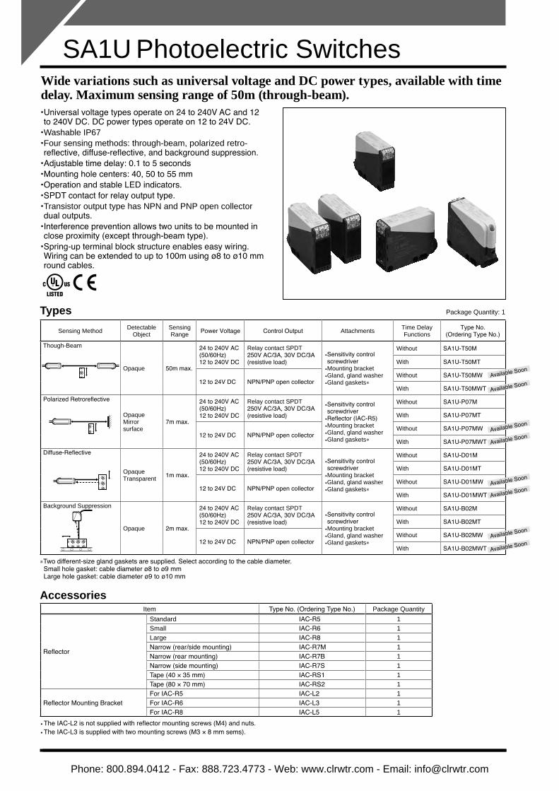
Wide variations such as universal voltage and DC power types, available with time delay. Maximum sensing range of 50m (through-beam). Universal voltage types operate on 24 to 240V AC and 12• to 240V DC. DC power types operate on 12 to 24V DC.Washable IP67• Four sensing methods: through-beam, • polarized retro-reflective, diffuse-reflective, and background suppression.Adjustable time delay: 0.1 to 5 seconds• Mounting hole centers: 40, 50 to 55 mm• Operation and stable LED indicators.• SPDT contact for relay output type.• Transistor output type has NPN and PNP open collector• dual outputs.Interference prevention allows two units to be mounted in• close proximity (except through-beam type).Spring-up terminal block structure enables easy wiring.• Wiring can be extended to up to 100m using ø8 to ø10 mmround cables.
Types Package Quantity: 1
Sensing Method Detectable Object
Sensing Range Power Voltage Control Output Attachments Time Delay
FunctionsType No.
(Ordering Type No.)
Though-Beam
Opaque 50m max.
24 to 240V AC (50/60Hz)12 to 240V DC
Relay contact SPDT250V AC/3A, 30V DC/3A (resistive load)
Sensitivity control • screwdriverMounting bracket• Gland, gland washer • Gland gaskets• *
Without SA1U-T50M
With SA1U-T50MT
12 to 24V DC NPN/PNP open collectorWithout SA1U-T50MW
With SA1U-T50MWTPolarized Retroreflective
OpaqueMirror surface
7m max.
24 to 240V AC(50/60Hz)12 to 240V DC
Relay contact SPDT250V AC/3A, 30V DC/3A (resistive load)
Sensitivity control • screwdriverReflector (IAC-R5)• Mounting bracket• Gland, gland washer • Gland gaskets• *
Without SA1U-P07M
With SA1U-P07MT
12 to 24V DC NPN/PNP open collectorWithout SA1U-P07MW
With SA1U-P07MWTDiffuse-Reflective
OpaqueTransparent 1m max.
24 to 240V AC(50/60Hz)12 to 240V DC
Relay contact SPDT250V AC/3A, 30V DC/3A (resistive load)
Sensitivity control • screwdriverMounting bracket• Gland, gland washer • Gland gaskets• *
Without SA1U-D01M
With SA1U-D01MT
12 to 24V DC NPN/PNP open collectorWithout SA1U-D01MW
With SA1U-D01MWTBackground Suppression
Opaque 2m max.
24 to 240V AC(50/60Hz)12 to 240V DC
Relay contact SPDT250V AC/3A, 30V DC/3A (resistive load)
Sensitivity control • screwdriverMounting bracket• Gland, gland washer • Gland gaskets• *
Without SA1U-B02M
With SA1U-B02MT
12 to 24V DC NPN/PNP open collectorWithout SA1U-B02MW
With SA1U-B02MWT
*Two different-size gland gaskets are supplied. Select according to the cable diameter.Small hole gasket: cable diameter ø8 to ø9 mm Large hole gasket: cable diameter ø9 to ø10 mm
AccessoriesItem Type No. (Ordering Type No.) Package Quantity
Reflector
Standard IAC-R5 1Small IAC-R6 1Large IAC-R8 1Narrow (rear/side mounting) IAC-R7M 1Narrow (rear mounting) IAC-R7B 1Narrow (side mounting) IAC-R7S 1Tape (40 × 35 mm) IAC-RS1 1Tape (80 × 70 mm) IAC-RS2 1
Reflector Mounting BracketFor IAC-R5 IAC-L2 1For IAC-R6 IAC-L3 1For IAC-R8 IAC-L5 1
The IAC-L2 is not supplied with reflector mounting screws (M4) and nuts.• The IAC-L3 is supplied with two mounting screws (M3 • × 8 mm sems).
SA1U Photoelectric Switches
Available Soon
Available Soon
Available Soon
Available Soon
Available Soon
Available Soon
Available Soon
Available Soon
Phone: 800.894.0412 - Fax: 888.723.4773 - Web: www.clrwtr.com - Email: [email protected]

SA1U Photoelectric Switches
Types Package Quantity: 1
Sensing Method DetectableObject
SensingRange Power Voltage Control Output Attachments Time Delay
FunctionsType No.
(Ordering Type No.)
Though-Beam
Opaque 50m max.
24 to 240V AC (50/60Hz)12 to 240V DC
Relay contact SPDT250V AC/3A, 30V DC/3A (resistive load)
Sensitivity control •screwdriverMounting bracket•Gland, gland washer •Gland gaskets• *
Without SA1U-T50M
With SA1U-T50MT
12 to 24V DC NPN/PNP open collectorWithout SA1U-T50MW
With SA1U-T50MWTPolarized Retroreflective
OpaqueMirror surface
7m max.
24 to 240V AC(50/60Hz)12 to 240V DC
Relay contact SPDT250V AC/3A, 30V DC/3A (resistive load)
Sensitivity control •screwdriverReflector (IAC-R5)•Mounting bracket•Gland, gland washer •Gland gaskets• *
Without SA1U-P07M
With SA1U-P07MT
12 to 24V DC NPN/PNP open collectorWithout SA1U-P07MW
With SA1U-P07MWTDiffuse-Reflective
OpaqueTransparent 1m max.
24 to 240V AC(50/60Hz)12 to 240V DC
Relay contact SPDT250V AC/3A, 30V DC/3A (resistive load)
Sensitivity control •screwdriverMounting bracket•Gland, gland washer •Gland gaskets• *
Without SA1U-D01M
With SA1U-D01MT
12 to 24V DC NPN/PNP open collectorWithout SA1U-D01MW
With SA1U-D01MWTBackground Suppression
Opaque 2m max.
24 to 240V AC(50/60Hz)12 to 240V DC
Relay contact SPDT250V AC/3A, 30V DC/3A (resistive load)
Sensitivity control •screwdriverMounting bracket•Gland, gland washer •Gland gaskets• *
Without SA1U-B02M
With SA1U-B02MT
12 to 24V DC NPN/PNP open collectorWithout SA1U-B02MW
With SA1U-B02MWT
*Two different-size gland gaskets are supplied. Select according to the cable diameter. Small hole gasket: cable diameter ø8 to ø9 mm Large hole gasket: cable diameter ø9 to ø10 mm
Specifications•Universal Voltage TypeSensing Method Through-Beam Polarized Retroreflective Diffuse-Reflective Background Suppression
Type No. SA1U-T50MSA1U-T50MT
SA1U-P07MSA1U-P07MT
SA1U-D01MSA1U-D01MT
SA1U-B02MSA1U-B02MT
Power Voltage 24 to 240V AC (21.6 to 264V AC) 50/60Hz, 12 to 240V DC (10.8 to 264V DC) compatible
Power Consumption Projector: 3 VA maximumReceiver: 3 VA maximum 3 VA maximum
Control OutputRelay contact SPDT, switching capacity: 250V AC/3A (resistive load), 30V DC/3A (resistive load)Electrical life (minimum operations): 100,000 (NO contact), 50,000 (NC contact) Mechanical life (minimum operations): 50,000,000
Minimum Applicable Load 5V DC, 10 mA minimum (reference value)Response Time 20 ms maximumInsulation Resistance Between power and output terminals: 20 MΩ minimum (500V DC megger)Dielectric Strength Between power and output terminals: 1500V AC, 1 minute, Between output terminals: 750V AC, 1 minuteWeight (approx.) Projector: 115g, Receiver: 130g 130g
•DC Power TypeSensing Method Through-Beam Polarized Retroreflective Diffuse-Reflective Background Suppression
Type No. SA1U-T50MWSA1U-T50MWT
SA1U-P07MWSA1U-P07MWT
SA1U-D01MWSA1U-D01MWT
SA1U-B02MWSA1U-B02MWT
Power Voltage 12 to 24V DC (10 to 30V DC) ripple rate 10% p-p maximum
Current Draw Projector: 20 mA maximumReceiver: 25 mA maximum 30 mA maximum
Control Output
Type NPN, PNP open collector (dual output)Load Current NPN: 100 mA maximum, PNP: 100 mA maximum Applied Voltage 30V DC maximumVoltage Drop NPN: 2.4V maximum, PNP: 2.4V maximum
Response Time 1 ms maximumInsulation Resistance Between live and dead parts: 20 MΩ minimum (500V DC megger)Dielectric Strength Between live and dead parts: 1000V AC, 1 minuteWeight (approx.) Projector: 105g, Receiver: 110g 110g
•Common SpecificationsSensing Method Through-Beam Polarized Retroreflective Diffuse-Reflective Background Suppression
Sensing Distance 50m maximum 0.2 to 7m (when using supplied reflector IAC-R5)
1m maximum (200 × 200 mm white mat paper)
0.2 to 2m (200 × 200 mm white mat paper)
Preset Distance — 0.4 to 2m (200 × 200 mm white mat paper)
Detectable Object Opaque Opaque/Mirror surface Opaque/Transparent OpaqueHysteresis — — 20% of sensing distance max. 15% of sensing distance max.Operation Mode Light ON or Dark ON (mode selector)
Control Output [Projector] Power LED: Green[Receiver] Operation LED:Yellow
Stable LED: GreenOperation LED: YellowStable LED: Green Operation LED: Yellow
Light Emitting Element Infrared LED (870 nm) Red LED (660 nm) Infrared LED (870 nm)Sensitivity Adjustment 1-turn control knob 8-turn control knobExtraneous Light Immunity Sunlight: 10,000 lux maximum, Incandescent lamp: 5,000 lux maximum
Vibration Resistance Damage limits: 10 to 55 Hz, amplitude 1.5 mm, 30 minutes in each axisShock Resistance Damage limits: 500 m/s2, 3 shocks each in 6 axes 3 consecutive timesOperating Temperature −25 to +60℃ (no freezing), storage temperature: −40 to +70℃Operating Humidity 35 to 85% RH (no condensation), storage humidity: 35 to 85% RHConnection Method Terminal block with M3 spring-up screwsApplicable Cable Outside diameter ø8 to ø10 mm (core 0.3 to 0.75 mm2)Cable Extension Extendable up to 100m with a cabtyre cable of 0.3 mm2 minimumHousing Material PBT (indicator cover: PC)Lens Material PC/PET PMMA PC/PETDegree of Protection IP67 (IEC/EN60529)
•Time Delay SpecificationsSensing Method Through-Beam Polarized Retroreflective Diffuse-Reflective Background Suppression
Type No. SA1U-T50MTSA1U-T50MWT
SA1U-P07MTSA1U-P07MWT
SA1U-D01MTSA1U-D01MWT
SA1U-B02MTSA1U-B02MWT
Time Range 0.1 to 5.0 sec (adjusted with the 1-turn control knob)Time Delay Function One shot, ON delay, OFF delay, and normal (no delay limit operation) modesTemperature Effect of Time Delay ±10% maximum of the time delay for 20ºC temperature rise within the operating temperature range
Repetitive Accuracy of Time Delay ±1.0% maximum of the time delay for repetitive inputs at 10 seconds or more
Phone: 800.894.0412 - Fax: 888.723.4773 - Web: www.clrwtr.com - Email: [email protected]

SA1U Photoelectric Switches
Universal voltage power supplycircuit
NOCOM
NC
Power supply24 to 240V AC (50/60Hz)or 12 to 240V DC
Power supply24 to 240V AC (50/60Hz)or 12 to 240V DC
Relay contactoutput (SPDT)
Main circuit
Main circuit
PNP
+V
+
–
+
–
OUT
NPN
0V
12 to 24V DC
OUT
Terminal No.
Terminal No.
Terminal No.
Load
Load
External Connection
External ConnectionInternal Circuit
Internal Circuit
1
2
1
5
4
3
2
1
1
3
4
2
2
All models except though-beam projector
[Univervsal Voltage Type] [DC Power Type]All models except though-beam projector
Though-beam projector Though-beam projector
Mai
n ci
rcui
tM
ain
circ
uit
12 to 24V DC
Uni
vers
al v
olta
gepo
wer
sup
ply
circ
uit
Descriptions
•Part Names
•Output Circuit / Connection Diagram•Part Names
•Operation Chart
•Output Circuit / Connection Diagram See the “Output Circuit / Connection Diagram” diagram above.
•Terminal Arrangement See the “Terminal Arrangement” diagram above.
•Operation Chart
Mode Selector (Light ON / Dark ON)
Operation LED (yellow) (Note 2)
Operation LED (yellow)
Stable LED (green) (Note 1)
Sensitivity Control (Note 2)
Sensing Range Control
Mode Selector (Light ON / Dark ON) ∗2
SA1U-T50M∗SA1U-P07M∗SA1U-D01M∗
SA1U-B02M∗
Timer Control ∗2
SA1U-T50M∗TSA1U-P07M∗TSA1U-D01M∗T
SA1U-B02M∗T
Operation LED (yellow)
Timer Control
Sensitivity Control ∗2
Mode Selector(Light ON / Dark ON, time delay mode)
Mode Selector ∗2(Light ON / Dark ON, time delay mode)
Sensing Range Control
Operation LED (yellow) ∗2
Stable LED (green) ∗1
Control Output
Control Output
OperationLED
OperationLED
Ligh
t ON
Dar
k O
NIncidentInterruption
ONOFF
ONOFF
ONOFF
ONOFF
OFF delay
Normal
One shot
ON delay
OFF delay
Normal
One shot
ON delay
Normal
0
1
2
3
4
5
6
7
8
9
ONOFF
ONOFF
ONOFF
ONOFF
ONOFF
ONOFF
ONOFF
ONOFF
ONOFF
Operation ModeMode
SelectorPosition
T T
T T
T T T
T T
T T T
T T
Ligh
t ON
Ligh
t ON
Dar
k O
N
IncidentInterruption
•Terminal Arrangement3
21
4 5
With
out T
ime
Del
ayW
ith T
ime
Del
ay
*1: Power LED for through-beam projector*2: Not available on through-beam projector
*1: Power LED for through-beam projector*2: Not available on through-beam projector
*Terminal ➄ not available on DC power types.
Phone: 800.894.0412 - Fax: 888.723.4773 - Web: www.clrwtr.com - Email: [email protected]

SA1U Photoelectric Switches
902540
30
67.5
5.5
1010
.5 10 5
22Polarized-reflective,Diffuse-reflective: receiver
Polarized-reflective: projectorBackground supression: projector
Diffuse-reflective: projector
Through-beam: projector/receiver
185
4050
557
Dimensions
•Photoelectric Switch
0.5
52 271.
276
.5 7614
.5
28.5 29 34 39 49
Polarized-reflective, Diffuse-reflective: receiver
Through-beam: projector/receiver
Diffuse-reflective: projectorPolarized-reflective: projector
Background supression: projector
70
55
2727
14.5
14.5
6
11
7.5R3
156
R3
152
•When the Mounting Bracket is Attached •Mounting Bracket
•Reflector
2-ø3.6 3.3
8.335.3
34.3
42.3
25
4(2
1)
IAC-R62-ø4.3
(Effective reflecting area: 47.2 × 47.2)(Effective reflecting area: 47 × 47)
(Effective reflecting area: 30 × 31)
51
72 60
39
IAC-R5
35
40
IAC-RS1
(thickness 0.5)
61
8
IAC-R8
2−ø4.53040
30.4
51.2
51.2
IAC-R7M (rear/side mounting) Positioning Projection(ø3.0, height 1.0)
• Effective reflecting area: 8.6 × 29.5• The mounting plate for reflector must be 0.8 to 2.5 mm.
• Effective reflecting area: 8.6 × 29.5• The mounting plate for reflector must be 0.8 to 2.5 mm.
• Effective reflecting area: 8.6 × 29.5• The mounting plate for reflector
must be 0.8 to 2.5 mm.
Positioning projection(ø3.0, height 1.0)
2-M3 tapping screw hole(ø2.6, depth 8.6)
M3 tapping screw hole(ø2.6, depth 7.7)
M3 tapping screw hole(ø2.6, depth 7.7)
M3 tapping screw hole(ø2.6, depth 8.6)
7.3
2-
3.012.4
33.3
25.4
12.4
11.5
IAC-R7B (rear mounting)
7.3
2-
12.4
33.3
12.4
11.5
IAC-R7S (side mounting)
7.3
2-
3.012.4
33.3
25.4
12.4
IAC-RS2
70
80
(thickness 0.5)
All dimensions in mm.
Phone: 800.894.0412 - Fax: 888.723.4773 - Web: www.clrwtr.com - Email: [email protected]
SA1U Photoelectric Switches
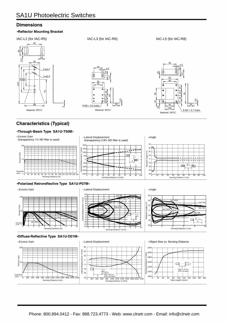
IAC-L2 (for IAC-R5)
4-ø4.4
2-ø3.4
42
5.5
19
6
28
58
70
376074
30
113
2
Material: SPCC
IAC-L3 (for IAC-R6)
254.5
1110
44
20
1.6
8-M3 × 0.5 holes
3525
1610
86
Material: SPCC 8-M4 × 0.7 holes
1615
187
4050
26
1235
(28)(3)
40
11
4.5
(3)
10
61
20
(2)
IAC-L5 (for IAC-R8)
Material: SPCC
Characteristics (Typical)
Lateral Displacement • (transparency 2.8% ND filter is used)
Lateral Displacement•
Excess Gain•
Angle•
Angle• Excess Gain•
Lateral Displacement• Object Size vs. Sensing Distance•
•Through-Beam Type SA1U-T50M*
•Polarized Retroreflective Type SA1U-P07M*
•Diffuse-Reflective Type SA1U-D01M*
•Reflector Mounting Bracket
Dimensions
Excess Gain • (transparency 1% ND filter is used)
1
10
100
0 10 20 30 40 50 60 70 80 90 100 110 120 130 140 150Sensing Distance (m)
OperationLevel
Exce
ss G
ain
-2000
-1500
-1000
-500
0
500
1000
1500
2000
0 10 20 30 40 50 60 70 80 90 100
X
Y
Late
ral D
ispl
acem
ent Y
(mm
)
Sensing Distance X (mm)
-40
-30
-20
-10
0
10
20
30
40
0 10 20 30 40 50 60 70 80 90 100Sensing Distance X (m)
X
θ
Rec
eive
r Ang
le θ
(º)
IAC-R7 IAC-R6IAC-R8
IAC-RS1
IAC-RS2 IAC-R5
10
100
0 1 2 3 4 5 6 7 8 9 101
Exce
ss G
ain
OperationLevel
Sensing Distance (m)-140-120-100-80-60-40-200
20406080
100120140
0 1 2 3 4 5 6 7 8 9 10
IAC-R5IAC-R6
IAC-R7
IAC-RS1IAC-RS2
IAC-R8
Late
ral D
ispl
acem
ent Y
(mm
)
Sensing Distance X (mm)
X
Y
-60
-40
-20
0
0
20
40
60
2 4 6 8 10
IAC-R5
IAC-R6IAC-R7
IAC-RS2
IAC-RS1
Xθ
IAC-R8
Ref
lect
or A
ngle
θ (º
)
Sensing Distance X (m)
-15
-5
5
15
25
35
800 1000 1200 1400 1600 1800 2000 2200
X
Y
Sensing Distance X (mm)
Late
ral D
ispl
acem
ent Y
(mm
)
Object:200 x 200 mmWhite mat paper
600-35 0 200 400
-25
1000
1200
1400
1600
1800
2000
2200
0 20 40 60 80 100 120 140 160 180 200
XA
Object: A mm white mat paper
Side Length A (mm)
Sens
ing
Dis
tanc
e X
(mm
)
1
10
100
0 200 400 600 800 1000 1200 1400 1600 1800 2000 2200
Exce
ss G
ain
OperationLevel
Sensing Distance (mm)
Phone: 800.894.0412 - Fax: 888.723.4773 - Web: www.clrwtr.com - Email: [email protected]

SA1U Photoelectric Switches
Control Knob vs. Sensing Distance• Sensing Distance vs. Hysteresis•
Light Beam Diameter•
•Background Suppression Type SA1U-B02M*
Lateral Displacement (preset 1m)• Lateral Displacement• (preset 2m)
Color Mat Paper and Other Materials•
Characteristics (Typical)
InstallationMake sure that there are no gaps between the cover and the hous-ing as shown in the diagram below.
To maintain waterproof characteristics, tighten the screws within the range of the recommended tightening torque.Excessive tightening may cause damage.
Screw Tightening Torque• Screw Recommended Tightening Torque (N·m)
Terminal screwGlandCover set screw Housing mounting screw
0.6 to 1.0 4.0 to 6.00.5 to 0.80.8 to 1.2
NotesWhen installing photoelectric switches, take into consideration the• reflecting light from the floor or walls as it may affect sensing of through-beam and background suppression types.Make sure to prevent sunlight, fluorescent light, and fluorescent• light of inverters from entering the receiver of the photoelectricswitch directly. Keep the through-beam type receiver away fromintense extraneous light.When installing SA1U photoelectric switches, do not tighten the• mounting screws excessively or hit the switch with a hammer,otherwise the protection degree cannot be maintained.Make sure that the supply voltage is within the rated values.• When using a switching regulator, be sure to ground the FG (frame• ground) terminal.To suppress a transient state at start-up, a circuit to turn off the•
output is installed (universal voltage type: 50 ms, DC power type: 100 ms). The timer will start after resetting the off output. To meet European Union Low Voltage Directives, install an EN ap-• proved fuse on the outside of the power terminal or output terminalof the universal voltage type SA1U photoelectric switches.Attach the cover properly to maintain waterproof characteristics.• Interference prevention allows two SA1U photoelectric switches to• be mounted in close proximity. However, the through-beam typeis not equipped with interference prevention. Maintain appropriatedistance between the switches referring to the lateral displacementcharacteristics on page 8.Polycarbonate or acrylic resins are used for optical elements. Do• not use ammonia or caustic soda for cleaning, otherwise opticalelements will dissolve. To remove dust and moisture build-up, usesoft dry cloth.When mounting the reflector, do not tighten the mounting screws• excessively, otherwise the screw hole of the reflector may be dam-aged.Use M4 mounting screws for the IAC-R5 and IAC-R8 reflectors and• M3 mounting screws for the IAC-R6 reflector. Tighten the mountingscrews to a tightening torque of 0.5 N·m maximum.Use the M3 self-tapping screw, flat washer, and spring washer to• tighten the IAC-R7 reflector to a torque of 0.5 to 0.6 N·m. Whileoptional reflector mounting bracket IAC-L2 is not supplied withmounting screws or nuts, the IAC-L3 and IAC-L5 are supplied withmounting screws for mounting the reflector on the bracket.IAC-RS1 and IAC-RS2 reflectors can be installed directly on a• flat surface using the adhesive tape attached to the back of thereflector. Before attaching the reflector, clean the surface to ensuresecure attachment.
Instructions
-80
-60
-40
-20
0
20
40
60
80
0 200 400 600 800 1000Sensing Distance X (mm)
X
Y
Whitepaper
Blackpaper
Late
ral D
ispl
acem
ent Y
(mm
)
Object: 200 × 200 mm mat paper∗Use white mat paper for sensing distance setting -100
-80-60-40-200
20406080
100
0 200 400 600 800 1000Sensing Distance X (mm)
Late
ral D
ispl
acem
ent Y
(mm
) Blackpaper
Whitepaper
1400 1600 1800 2000 2200
X
YObject: 200 × 200 mm mat paper∗Use white mat paper for sensing distance setting
12000
20
40
60
80
100
120
140
160
0 500 1000 1500 2000 2500Sensing Distance (mm)
Ligh
t Bea
m D
iam
eter
(mm
)
0
5
10
15
20
25
30
0 200 400 600 800 1000 1200 1400 1600 1800 2000 2200Sensing Distance (mm)
Hys
tere
sis
(%) Black paper
Gray paper
White paper
0500
100015002000250030003500400045005000
0 1 2 3 4 5 6 7 8Control Knob (turns)
Sens
ing
Dis
tanc
e (m
m)
WhitePaper
GrayPaper
BlackPaper
0
200
400
600
800
1000
Comparison of sensing distance when set to detect white mat paper ( 200) at 1m
Comparison of sensing distance when set to detect white mat paper ( 200) at 2m
Sens
ing
Dis
tanc
e (m
m)
Sens
ing
Dis
tanc
e (m
m)
0200400600800
100012001400160018002000
Whi
te
Red
Gre
enG
reen
Blue
Gra
y
Blac
k
Car
dboa
rd
Alum
inum
Stai
nles
s St
eel
Bras
s
Vene
er
Whi
te
Red Blue
Gra
y
Blac
k
Car
dboa
rd
Alum
inum
Stai
nles
s St
eel
Bras
s
Vene
er
No Gap
Cover Set Screw
Terminal Screw(5 pcs max.)
Housing MountingScrew (2 pcs)
Gland
Phone: 800.894.0412 - Fax: 888.723.4773 - Web: www.clrwtr.com - Email: [email protected]

SA1U Photoelectric Switches
•Installing the Background Suppression (BGS) TypeInstall the sensor head as shown below to minimize sensing er-rors.
Object
Correct Correct Incorrect
ObjectObject
Wiring•Connecting Cables
Recommended insulation length (A)Terminal No.Length “A” (mm)
➀
45➁
30➂
55➃
40➄
25
Gland
Gland washer Gland gasket(2 types supplied. Choose according to cable diameter)
ø8 to 10 mm
Approx.10 mm
➀
➀
➁
➁
➂
➂
➃
➃
➄
➄
A
Connect the cables to the correct terminal number. Connect the • lower terminal screws first.Attach the cover and secure with the set screw.• *To maintain waterproof and dustproof characteristics, use cab-tyre cables (do not use soft cables as it may fall out) with ø8 to ø10 mm diameter. Install the attached gland gasket and washer and tighten the gland securely. For the small gland gasket, use a cable with ø8 to ø10 mm diameter. For the large gland gas-ket, use a cable with ø9 to ø10 mm diameter. The cable sheath should be 10 mm approx. Make sure that the gland washer fits in the groove of the gasket.
When wiring, make sure that the power is turned off.• Incorrect wiring may cause damage to the internal circuit.• Avoid parallel wiring with high-voltage or power lines (especially • inverters) in the same conduit, otherwise noise may cause mal-function and damage. When wiring is long or may be affected by power lines, use a • separate conduit for wiring.Use a cable of 0.3 mm• 2 minimum core wires. The cable can be extended up to 100m. For DC power types, voltage drop due to resistance of the cable lead wire should be taken into consider-ation.
When using crimp terminals, make sure that the terminals do not • come into contact with adjacent terminals. For correct installation, see the figure below.
IncorrectCorrect
•Dimension of Applicable Crimping TerminalsDimensions in mm.
Ring Terminal Spade Terminal
ø3.2 min.
6.0 max. 6.0 max.
5.2 min.11.0 max.3.3 max.
ø3.2 min.
6.0 max. 6.0 max.
5.2 min.
11.0 max.5.0 max.
When using insulation for ring terminals, use an insulating sheath.• Install the insulation sheath to the crimp part before wiring.• Only one crimp terminal can be connected per terminal.•
Indicator and Output OperationSE
NS.
L-O
ND
-ON
Operation LED (yellow)
Stable LED (green)
The operation LED turns on (yellow) when the control output is on. The stable LED turns on (green) either at stable incident or stable interruption. Make sure to use the SA1U photoelectric switch after the stable LED is on.See the table below.
Light Receiving
Status
StableLED
(green)
Operation LED (yellow)/Control Output
Light ON Dark ONStable
Incident ONON OFFUnstable
Incident OFFUnstableInterruption OFF ONStableInterruption ON
Instructions
Phone: 800.894.0412 - Fax: 888.723.4773 - Web: www.clrwtr.com - Email: [email protected]
SA1U Photoelectric Switches
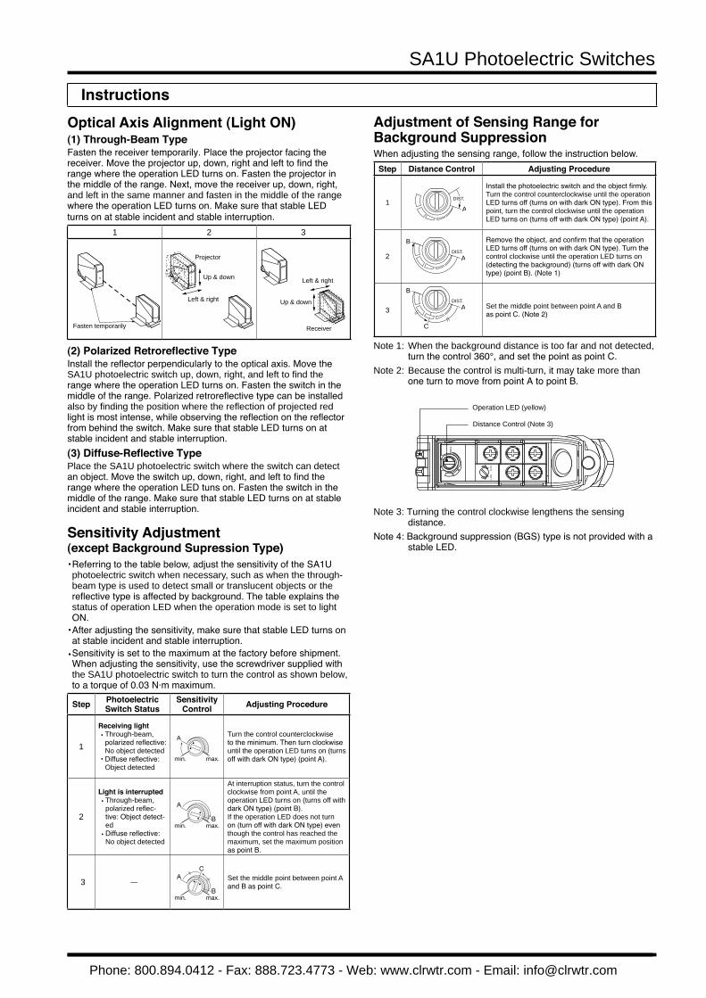
Optical Axis Alignment (Light ON)(1) Through-Beam TypeFasten the receiver temporarily. Place the projector facing thereceiver. Move the projector up, down, right and left to find therange where the operation LED turns on. Fasten the projector inthe middle of the range. Next, move the receiver up, down, right,and left in the same manner and fasten in the middle of the rangewhere the operation LED turns on. Make sure that stable LED turns on at stable incident and stable interruption.
1 2 3
Fasten temporarily
Up & down
Left & right
Projector
Receiver
Up & down
Left & right
(2) Polarized Retroreflective TypeInstall the reflector perpendicularly to the optical axis. Move the SA1U photoelectric switch up, down, right, and left to find the range where the operation LED turns on. Fasten the switch in the middle of the range. Polarized retroreflective type can be installed also by finding the position where the reflection of projected red light is most intense, while observing the reflection on the reflector from behind the switch. Make sure that stable LED turns on at stable incident and stable interruption.(3) Diffuse-Reflective TypePlace the SA1U photoelectric switch where the switch can detectan object. Move the switch up, down, right, and left to find therange where the operation LED tuns on. Fasten the switch in themiddle of the range. Make sure that stable LED turns on at stableincident and stable interruption.
Sensitivity Adjustment (except Background Supression Type)Referring to the table below, adjust the sensitivity of the SA1U • photoelectric switch when necessary, such as when the through-beam type is used to detect small or translucent objects or the reflective type is affected by background. The table explains the status of operation LED when the operation mode is set to light ON.After adjusting the sensitivity, make sure that stable LED turns on • at stable incident and stable interruption.Sensitivity is set to the maximum at the factory before shipment.• When adjusting the sensitivity, use the screwdriver supplied with the SA1U photoelectric switch to turn the control as shown below, to a torque of 0.03 N·m maximum.
Step PhotoelectricSwitch Status
SensitivityControl Adjusting Procedure
1
Receiving lightThrough-beam, • polarized reflective: No object detectedDiffuse reflective: • Object detected
A
min. max.
Turn the control counterclockwiseto the minimum. Then turn clockwiseuntil the operation LED turns on (turns off with dark ON type) (point A).
2
Light is interruptedThrough-beam, • polarized reflec-tive: Object detect-edDiffuse reflective: • No object detected
A
Bmin. max.
At interruption status, turn the control clockwise from point A, until the operation LED turns on (turns off with dark ON type) (point B).If the operation LED does not turn on (turn off with dark ON type) even though the control has reached the maximum, set the maximum position as point B.
3 —A
C
Bmin. max.
Set the middle point between point A and B as point C.
Adjustment of Sensing Range for Background SuppressionWhen adjusting the sensing range, follow the instruction below.
Step Distance Control Adjusting Procedure
1A
DIST.
Install the photoelectric switch and the object firmly. Turn the control counterclockwise until the operation LED turns off (turns on with dark ON type). From this point, turn the control clockwise until the operation LED turns on (turns off with dark ON type) (point A).
2DIST.
A
B Remove the object, and confirm that the operation LED turns off (turns on with dark ON type). Turn the control clockwise until the operation LED turns on (detecting the background) (turns off with dark ON type) (point B). (Note 1)
3DIST.
A
C
B
Set the middle point between point A and Bas point C. (Note 2)
Note 1: When the background distance is too far and not detected, turn the control 360°, and set the point as point C.
Note 2: Because the control is multi-turn, it may take more than one turn to move from point A to point B.
DIS
T.
L-O
ND
-ON
Operation LED (yellow)
Distance Control (Note 3)
Note 3: Turning the control clockwise lengthens the sensing distance.
Note 4: Background suppression (BGS) type is not provided with a stable LED.
Instructions
Phone: 800.894.0412 - Fax: 888.723.4773 - Web: www.clrwtr.com - Email: [email protected]
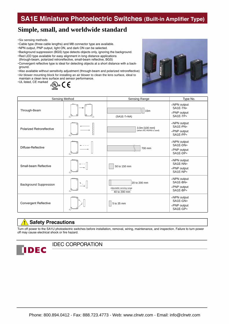
Six sensing methods• Cable type (three cable lengths) and M8 connector type are available.• NPN output, PNP output, light ON, and dark ON can be selected.• Background suppression (BGS) type detects objects only, ignoring the background.• Red LED type available for easy alignment in long distance applications • (through-beam, polarized retroreflective, small-beam reflective, BGS)Convergent reflective type is ideal for detecting objects at a short distance with a back-• ground.Also available without sensitivity adjustment (through-beam and polarized retroreflective)• Air blower mounting block for installing an air blower to clean the lens surface, ideal to • maintain a clean lens surface and sensor performance.UL listed, CE marked•
Simple, small, and worldwide standardSA1E Miniature Photoelectric Switches (Built-in Amplifier Type)
Sensing Method Sensing Range Type No.
Through-Beam 15m
(SA1E-T∗NA)
NPN output • SA1E-TN*
PNP output • SA1E-TP*
Polarized Retroreflective 3.0m [100 mm](when IAC-R5/R8 is used)
NPN output • SA1E-PN*
PNP output • SA1E-PP*
Diffuse-Reflective 700 mm
NPN output • SA1E-DN*
PNP output • SA1E-DP*
Small-beam Reflective 50 to 150 mm
NPN output • SA1E-NN*
PNP output • SA1E-NP*
Background Suppression 20 to 200 mm
40 to 200 mmAdjustable sensing range
NPN output • SA1E-BN*
PNP output • SA1E-BP*
Convergent Reflective 5 to 35 mm
NPN output • SA1E-GN*
PNP output • SA1E-GP*
Safety PrecautionsTurn off power to the SA1U photoelectric switches before installation, removal, wiring, maintenance, and inspection. Failure to turn power off may cause electrical shock or fire hazard.
Phone: 800.894.0412 - Fax: 888.723.4773 - Web: www.clrwtr.com - Email: [email protected]