ieee-pes psrc report on design and testing of selected system integrity protection schemes
TRANSCRIPT

7/21/2019 IEEE-PES PSRC Report on Design and Testing of Selected System Integrity Protection Schemes
http://slidepdf.com/reader/full/ieee-pes-psrc-report-on-design-and-testing-of-selected-system-integrity-protection 1/5
1
Abstract—This paper is a summary of an IEEE/PES Power
System Relaying Committee (PSRC) report [2] on the design and
testing of selected System Integrity Protection Schemes (SIPS).
The report includes high level general considerations in SIPS
design and testing, and the industry practice in design and testing
of the following selected SIPS with example implemented
schemes: (1) Generator rejection; (2) Load rejection; (3) Adaptiveload mitigation; (4) Dynamic braking; and (5) System separation.
Index Terms—System Integrity Protection Scheme, Remedial
Action Scheme, System Protection System, Generator Rejection,
Load Rejection, Adaptive Load Mitigation, Dynamic Braking,
System Separation
I. I NTRODUCTION
n IEEE transaction paper, “IEEE PSRC Report on Global
Industry Experiences with System Integrity Protection
Schemes (SIPS)” [1], has shown wide application of various
types of system integrity protection schemes (SIPS) in the
global power industry. Unlike conventional protection systemsthat are applied to protect a specific power system element,
such as a generator, a transformer, a line, and so on, SIPS are
applied to protect the integrity of the power system or strategic
portions of the system. SIPS encompass Special Protection
Schemes (SPS), Remedial Action Schemes (RAS) and
varieties of other safety nets. These schemes provide
reasonable countermeasures to prevent, slowdown and/or stop
cascading outages caused by several levels of contingencies.
According to the survey results of the paper [1], SIPS in use
today include
• Generator Rejection
•
Load Rejection• Under-Frequency Load Shedding
• Under-Voltage Load Shedding
• Adaptive Load Mitigation
• Out-of-Step Tripping
• Voltage Instability Advance Warning Scheme
• Angular Stability Advance Warning Scheme
• Overload Mitigation
• Congestion Mitigation
• System Separation
• Shunt Capacitor Switching
• Tap-Changer Control
• SVC/STATCOM Control
• Turbine Valve Control
• HVDC Controls
•
Power System Stabilizer Control
• Discrete Excitation
• Dynamic Braking
• Generator Runback
• Bypassing Series Capacitor
• Black-Start or Gas-Turbine Start-Up
• AGC Actions
• Busbar Splitting
SIPS often are the last line of defense for preventing the
protected power system or portions of the system from
cascading outages. The proper design, documentation, and
testing of SIPS is the basis for reliable and accurate operation
of such schemes. For some SIPS, their design and/or testing
have been studied extensively over the years, such as the
under-frequency load shedding scheme [3], out-of-step
tripping [4], etc., while other SIPS (e.g. generator rejection,
load rejection, etc.), which are also in wide use in power
systems [1], are less studied.
This IEEE/PES PSRC report, “Design and Testing of
Selected System Integrity Protection Schemes”, was developed
to provide practical design examples for five widely used
SIPS: (1) Generator rejection; (2) Load rejection; (3) Adaptive
load mitigation; (4) Dynamic braking; and (5) System
separation.The report includes information in two main areas: the high
level general considerations in SIPS design and testing, and
more detailed specific design considerations and the testing for
the selected five SIPS design and application examples.
II. GENERAL CONSIDERATIONS IN SIPS DESIGN AND TESTING
Although SIPS are typically different from each other
because their applications are specific to special requirements,
there are some considerations in their design and testing that
are generally common to them all. The report has included the
IEEE/PES PSRC Report on Design and Testing of
Selected System Integrity Protection Schemes
Jonathan Sykes, Senior Member, IEEE , Pacific Gas & Electric, 6111 Bollinger Canyon Rd., San
Ramon, CA 94602USA (phone: 925-328-5470; e-mail: [email protected]).
Yi Hu, Senior Member, IEEE , Quanta Technology LLC, 4020 Westchase Blvd. Suite 300, Raleigh,
NC 27607, USA (phone: 919-334-3042; e-mail: [email protected]).
Alexander Apostolov, Fellow, IEEE, OMICRON electronics, 2950 Bentley Ave, Los Angeles, CA
90064, USA (phone: 310-478-5967; e-mail: [email protected]).
A

7/21/2019 IEEE-PES PSRC Report on Design and Testing of Selected System Integrity Protection Schemes
http://slidepdf.com/reader/full/ieee-pes-psrc-report-on-design-and-testing-of-selected-system-integrity-protection 2/5
2
following general considerations in SIPS design and testing:
Power system hierarchy
The specific hierarchy of the electric power system needs to
be considered in the design and implementation of SIPS.
Today’s electric power system is very complex, consisting of a
large number of generation power plants that generate electric
power for delivery to the loads through highly interconnected
transmission systems and distribution networks. The growingnumber of distributed generation units, renewable generation
resources, and micro-grids further increases the complexity of
the modern power systems.
The electric power system is operated with energy
management systems to maintain generation-load balance of
the system typically with sufficient security margin to
withstand certain system disturbances and contingencies, such
as loss of a transmission line and/or a generating unit.
When the power system cannot be operated securely against
such contingencies or when multiple contingencies occurring
within a very short time period which may result in system
instability or overloaded elements, a SIPS should be
considered. The action of the SIPS may decelerate the system,
reestablish the balance between load and generation, isolate
the unstable parts of the system, or unload the overloaded
elements. These SIPS actions highly depend on the hierarchy
of the part of the power system where they are applied and
must be properly considered and addressed in the SIPS design.
Generic SIPS Description Model
Although specific SIPS may have very different
architecture and use different components, they can be
described using a generic model as shown below (Fig. 1), i.e.
all SIPS can be described to have monitoring and detection,
communication, decision making, and mitigation measureexecution part.
Processor 1
Processor 2
Processor 3
Switch
Router
Switch Router
Centralized Processor ACentralized Processor B
Substation #1 (SIPS B)
Substation #1 (SIPS A)
Substation #N (SIPS A)Substation #N (SIPS B)
Relay Relay
Switch Router
Gen. Plant or Load Sub. #M (SIPS B)
Relaywith
Logic
Switch
Router
I. Monitoring & Detection1. Line flow monitoring
2. Line outage detection
II. SIPS Logic Processing1. Arming Calculations & logic checks
2. Mitigation Level Calculations
III. Mitigation1. Generation/load level monitoring
2. Generation Tripping/load shedding
Gen. Plant or Load Sub. #M (SIPS A)
Gen. Plant or Load Sub. #1 (SIPS A)Gen. Plant or Load Sub. #1 (SIPS B)
Generationor
Load
TelecommunicationsNetwork A
TelecommunicationsNetwork B
Fig. 1. Generalized SIPS Architecture
Communications Requirements
Communications are used by SIPS to acquire data from
distant locations for the central controller where the decision
for any action is made. Communications are also used to send
SIPS control commands to the field to execute the mitigation
action. In order to assure power system stability, SIPS signals
transmission requires the communications system that it uses
to meet specific speed, security and dependability
requirements. The report described typical communication
media commonly used in various SIPS and their typical delay
values.
Centralized SIPS vs. Distributed SIPS
SIPS could be designed to have either a centralized or a
distributed architecture. In centralized SIPS, all logic processing and arming is done at a central site, and only
input/output (I/O) interface devices are deployed at the remote
sites. In distributed SIPS, the logic processing and arming
functionality is distributed across the various stations or
hierarchical levels. The logic processor at each station can
independently initiate control actions. The design choice
should be based on the specific design requirements.
Redundancy Considerations
Failure of the SIPS to operate when required, or its
undesired or unintentional operation may have adverse impact
on the power system. Therefore, design of the SIPS often
involves redundancy or some backup functions. Althoughsimple redundancy or backup systems will improve the
dependability of the system it will reduce the security of the
overall system. To maintain the security level of a single
system and achieve the dependability of a redundant system a
two out of three voting system may be needed. Redundant
systems also improve operations and maintenance efficiency
by minimizing downtime, and the overall life cycle support.
One drawback of redundant systems is increased hardware
complexity. Depending on the application philosophy of
primary and redundant applications being same or different
hardware (component), additional training costs and need for
more spare parts may also be considered as drawbacks.However, if product and type of hardware used are common to
other (conventional) protection and control applications, then
added hardware and training are addressed from a “Program”
level at the power company.
Functional and System Testing of SIPS
Functional and system test plays an important role in
confirming how well a SIPS satisfies its design requirements at
any given time or under any specific conditions. Functional
testing is the most widely accepted practice for protection and
control systems and is required to ensure that the SIPS and
each of its components will operate as designed under different
system conditions.Understanding what has or has not been tested in a complex
system is still a major challenge for many organizations. The
time commitment required for quality assurance functional
testing needs to be one of the highest priorities for ensuring
successful operation of the SIPS. It is essential that the
functional testing requirements, test cases, test methods and
tools are considered and defined as part of all stages of the
engineering of the SIPS.
With functional testing the engineering, commissioning and
maintenance teams translate functional requirements into
7/21/2019 IEEE-PES PSRC Report on Design and Testing of Selected System Integrity Protection Schemes
http://slidepdf.com/reader/full/ieee-pes-psrc-report-on-design-and-testing-of-selected-system-integrity-protection 3/5
3
executable test cases that confirm how well the SIPS satisfies
the requirements at any given time or under any specific
conditions. A test plan needs to be developed in order to build
a suite of executable tests that define and verify the
functionality requirements, providing a fast and objective way
to assess the performance of the tested function. It is important
to include in this test plan the simulation of common events
and conditions for which the SIPS should not operate,
particularly when the consequences of false operation areharmful to the system or costly. This process should start
together with the design of the SIPS and follow through at
each step until the detailed test plan for the SIPS and each of
its components is defined. These tests can then be executed
regularly to ensure that functional modifications or firmware
upgrades do not unintentionally change previously verified
functionality.
An effective functional testing practice involves the
definition of guidelines for using functional testing
technologies effectively (based on the user’s protection testing
philosophy), and then the implementation and integration of
those guidelines into the asset management system.To achieve effective system testing, the user or
manufacturer must not only have a defined practice for its use,
but that practice must be implemented and integrated into the
engineering process so that it can be used consistently and
regularly across the organization. The definition of the
functional tests will be part of the design and testing
documentation of the SIPS. At the time when the functionality
of every single element of the SIPS is designed, it must be
specified how it is going to be tested.
Utility Documents
The design and testing of SIPS may need to follow the
requirements of reliability coordination authorities in additionto utility’s own guidelines. Individual utilities have also
developed whitepapers and internal guidelines about the SIPS
for their own use. These documents should be consulted and
the requirements should be followed in the SIPS design,
documentation, and testing guidelines to ensure compliance
where they are implemented.
III. PRACTICAL EXAMPLES OF SELECTED SIPS
The report included practical design examples for five
widely used SIPS: (1) Generator rejection; (2) Load rejection;
(3) Adaptive load mitigation; (4) Dynamic braking; and (5)
System separation.
Generator rejection
Generation rejection schemes involve tripping of one or
more generating units. The practice of generator tripping is
used on all kinds of units but especially on hydro-generator
units. Generation rejection improves transient stability by
reducing the accelerating torque on the machines that remain
in service after a disturbance. Generation rejection can also be
used to reduce power transfers on certain parts of a
transmission system and thus solve overload or voltage
stability problems.
The generator rejection design example provided in this
report is for a four unit coal-fired electrical generating plant
(the Plant) located in the western United States. The plant has
the capacity of a net output of 2120 MW, and it is remote from
the load and connected to a transmission network by three long
345 kV and two 230 kV transmission lines. When the
transmission path is being operated at the path load transfer
limit and a transmission line in the path is lost, the generationat the Plant must be reduced to maintain the transient stability
of the power grid. To arrest the transient power swing
following the clearing of the line fault from dropping the
voltage below 0.3 per unit, a SIPS that trips generating units at
the Plant is deployed.
Load rejection
Load rejection is a protection system designed to trip load
following an event or disturbance that causes supply-load
unbalances that may lead to a wide area disturbance. Load
rejection SIPS typically are designed to keep a system or sub-
system in parallel with the remaining parts of the system in
case of the loss of a major supply to the affected power system
area. Load rejection differs from the automatic under-
frequency load shedding, since one of SIPS main goals is to
prevent the separation of an area of the system before the
change of frequency can result in the operation of the under-
frequency relays.
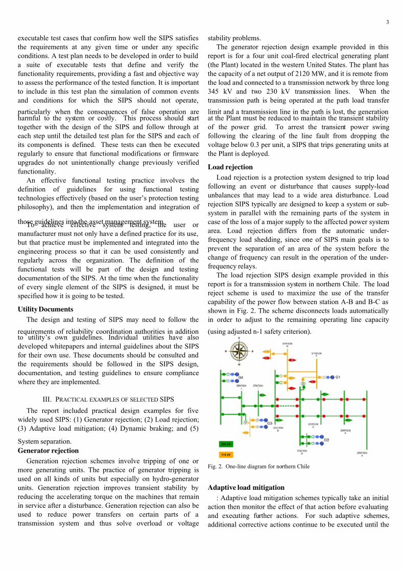
The load rejection SIPS design example provided in this
report is for a transmission system in northern Chile. The load
reject scheme is used to maximize the use of the transfer
capability of the power flow between station A-B and B-C as
shown in Fig. 2. The scheme disconnects loads automatically
in order to adjust to the remaining operating line capacity
(using adjusted n-1 safety criterion).
Fig. 2. One-line diagram for northern Chile
Adaptive load mitigation
: Adaptive load mitigation schemes typically take an initial
action then monitor the effect of that action before evaluating
and executing further actions. For such adaptive schemes,
additional corrective actions continue to be executed until the

7/21/2019 IEEE-PES PSRC Report on Design and Testing of Selected System Integrity Protection Schemes
http://slidepdf.com/reader/full/ieee-pes-psrc-report-on-design-and-testing-of-selected-system-integrity-protection 4/5
4
congestion is mitigated and system is relieved. The arming of
such schemes determines the mode of operation and whether
the system adjustments need to be immediate or the conditions
support more gradual balancing of load and system capability,
including generation.
The adaptive load mitigation SIPS design example
provided in the report is for an area in Western US that is
served by five 115 kV transmission lines (Fig. 3). Generation
station N is substantially less economic to operate than otheravailable generation sources for the area, but is a designated as
a must-run station for minimizing risks of operating the area.
The other two “source” 115 kV lines (D and E) connect the
area to more economical generation and stronger transmission
sources. Loss of line E, by itself, does not result in system
performance outside acceptable limits. However, various
contingency conditions (e.g. loss of line D, outages on 230 kV
system, etc.) could result in an overload of line E by as much
as 60% above its thermal rating. Without additional
transmission line capability the only solution is load shedding
in the area. The amount of load that must be shed varies as a
function of the actual load at the time of the critical outage,hence an adaptive load mitigation scheme is used.
Fig. 3. One-line diagram of the 115 kV system
Dynamic braking
A dynamic brake is a resistive shunt type load that is
switched onto the power system briefly to help maintain
transient stability once a disturbance has occurred. For the
design example in this report, application of a dynamic brake
is used to enhance transient angular stability between adjacent
systems allowing one system to benefit from the other systems’
remotely located renewable power sources [5]. When first
installed, availability of this three-phase 1400 MW braking
scheme was thought to increase power transfer capability by
900 MW.
The dynamic braking scheme is applied to a system which
also has several other SIPS schemes in operation at any time.
Using dynamic braking scheme avoids the need for equivalent
generation reduction amounts using a gen rejection scheme
when the system is in export mode. The brake is applied at a
single location adjacent to large hydroelectric generation units
as part of a wide area protection scheme. The control is open
loop type, with fixed duration of application.
System separation
The system separation scheme design example included in
this report serves as the primary means for maintaining system
angular stability and maintain reliability within regulator
planning requirements such as NERC TPL-003 (or category C
– double contingency events). It will trip breakers at substationB, line 8 and 9 (Fig. 4) for unstable power swings separating
the system in two islands and block system separation for
stable power swings.
138 KV BUSMONITORING
SUBSTATION A
LINE 2 LINE 3LINE 1
LINE 5 LINE 6LINE 4
68 -1 68 -2
345 KV
BUS
LINE 8(REMOTE)
LINE 9(REMOTE)
V∠θ
E1∠θ = V∠θ + ITOTAL*X
X
ITOTAL
SUBSTATION DSUBSTATION B
SUBSTATION C
AUXILIARYTRANSFORMER
5/12.5 A
Fig. 4. Example system one-line diagram
The report provides more detailed description of design
considerations, the design details and the testing of these
examples.
IV. CONCLUSIONS
The SIPS included in this PSRC report demonstrated that
design and testing of SIPS are highly system dependent.
Specific system and grid conditions, such as grid topology,generation levels, load levels, load flow patterns, etc., greatly
influence the types of SIPS being selected. However, the
design and testing of a specific scheme of the same type of
SIPS should still take specific power system and grid
conditions into account.
SIPS can be very diverse in design. This requires owners
and the region to perform detailed and sometimes extensive
studies and apply the appropriate standards and oversight to
ensure the design meets acceptable performance requirements.
The examples in this report are intended to provide a reference
of design and testing techniques used to meet a specific
application and are not intended to apply without any change
to every SIPS of the same type.
V. ACKNOWLEDGMENT
This paper is based on the report created by IEEE Power
System Relaying Committee working group C15 and is
available at http://www.pes-psrc.org. The content of the report
is a collective effort of many industry members from IEEE
PSRC. The authors acknowledge contributions by the Working
Group members that have made this report [2] possible:

7/21/2019 IEEE-PES PSRC Report on Design and Testing of Selected System Integrity Protection Schemes
http://slidepdf.com/reader/full/ieee-pes-psrc-report-on-design-and-testing-of-selected-system-integrity-protection 5/5
5
Mark Adamiak, Bui Dac-Phuoc, Alla Deronja, Jim Ebrecht,
Gene Henneberg, Shinichi Imai, Vahid Madani, Dean Miller,
Alfredo De La Quintana, Benton Vandiver, Roger Whittaker,
Mohammad Zubair, and Solveig Ward.
The authors are also grateful to many guest working group
meeting attendees for their valuable input and comments
during the development of this report.
VI. R EFERENCES [1]
Vahid Madani, Damir Novosel, Stan Horowitz, Mark Adamiak, Javier
Amantegui, Daniel Karlsson, Shinichi Imai, Alexander Apostolov,
“IEEE PSRC Report on Global Industry Experiences with System
Integrity Protection Schemes (SIPS)”, IEEE Trans. on Power Delivery,
Volume 25, Issue 4, Oct. 2010, Page 2143 – 2155
[2]
IEEE/PES PSRC WG C15 Report, “Design and Testing of Selected
System Integrity Protection Schemes”, Nov. 2012
[3]
IEEE C37.117-2007, “IEEE Guide for the Application of Protective
Relays Used for Abnormal Frequency Load Shedding and Restoration”
[4]
IEEE/PES PSRC WG D6 Report, “Power Swing and Out-of-Step
Considerations on Transmission Lines”, July 2005
[5]
A. H. M. A. Rahim, and D. A. H. Alamgir, “A Closed-Loop Quasi-
Optimal Braking Resistor and Shunt Reactor Control Strategy for
Transient Stability Control”, IEEE Transactions on Power Systems, Vol.
3, No. 3, August 1988, pp. 879-886
BIOGRAPHIES
Jonanth Sykes (SM) is Manager of System Protection at
Pacific Gas and Electric Company in
Oakland California. Jonathan graduated
from the University of Arizona in 1982,
is a Professionally Licensed Electrical
Engineer, and has 30 years of
engineering experience in System
Protection. He is active on several
committees in the Western Electric
Coordinating Council and is past
Chairman of the North American Electric Reliability
Corporation System Protection and Control Subcommittee.
Jonathan has authored and co-authored papers for conferences
and publications and is an active senior member of IEEE and
regularly contributes to the Power System Relay
Committees. Jonathan has been involved in EHV protection
and control for over 15 years and established standards in
EHV relaying and SPS/RAS design and implementation.
Jonathan has been active in NERC and WECC standards
interpretation and development and is a subject matter expert
in the interpretation of various protection and critical
infrastructure related standards.
Yi Hu (SM’2005) received his B.Sc. degree from Southeast
University, China in 1982 and M.Sc.
degree from Nanjing Automation
Research Institute (NARI), China in
1984, in Electrical Engineering. He
received his Ph.D. degree in Electrical
and Computer Engineering from the
University of Manitoba in 1994. He was
with NARI, ABB, TEKELEC, KEMAConsulting and is currently with Quanta Technology. He is a
leading consultant in the areas of power system protection and
control, system modeling/analysis, testing and quality
assurance. Dr. Hu holds thirteen US patents. He has been and
continues to be involved in a number of large-scale PMU
system deployment projects. He is vice chair of IEEE/PES
PSRC WG C15, and chair of PSRC WG C21 and H21.
Alexander Apostolov (F) received MSc in Electrical
Engineering, MSc in Applied
Mathematics and Ph.D. from the
Technical University in Sofia, Bulgaria.He has more than 35 year experience in
power systems protection, automation,
control and communications. He is
Principal Engineer for OMICRON
electronics. He is IEEE Fellow, IEEE
Distinguished Lecturer and Member of
the Power Systems Relaying Committee. He is past Chairman
of the Relay Communications Subcommittee, serves on many
IEEE PES, IEC TC 57, IEC TC 95 and CIGRE B5 Working
Groups. He holds four patents, authored and presented more
than 400 technical papers. He is Editor-in-Chief of PAC
World.