iem cam catalog - clark and osborne · iem cam catalog service we deliver and quality you can...
TRANSCRIPT

IEMwww.danly.com
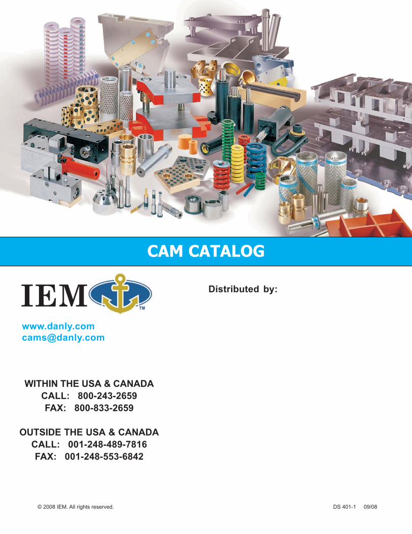
CAM CATALOGCAM CATALOGCAM CATALOG
TRUSTED SOLUTIONS AND INNOVATION
IEMIEM

IEMwww.danly.com CAM CATALOG
Service We Deliver and Quality You Can Depend OnIEM is a leading manufacturer of die sets and die component products supplied globally to the partsforming industry. Backed by years of tool and die experience, quality and innovation are some of thereasons why our name is respected throughout the world. We have taken the lead role in creating andbringing new products to customers and helping them find solutions that improve their operations.Based on the capabilities IEM offers, we can help you to meet the demands of quick deliveries,technical support, quality products and competitive prices. IEM and its broad distribution channelsand direct sales personnel will assist you in any way to make your product a better and moreprofitable one.
Whether you purchase on-line or in person, you will receive the same reliable service IEM is knownfor. We understand the demanding schedules of die builders and production personnel and havedeveloped efficient manufacturing processes to shorten product lead times as well as put inventoryon our shelves so you can have it in your facility when you need it. Put the IEM network to work foryou. We’ve got the service you’ve been looking for.
Included in our full line offering are both inch and metric size die sets and die components that aredesigned to numerous die standards including ISO, NAAMS, JIS and many large automotive andappliance manufacturers’ standards. The complete product offering includes:
• Ball bearing and friction style die sets including custom and catalog sets• Machined plate• Guide posts & bushings• ISO and JIS Die springs• In-die tapping units for both mechanical and hydraulic presses• Formathane® Urethane springs, strippers, sheets, bars, rods and die cover film• Diemakers’ supplies such as pry bars, dowel pins, hoist rings, clamps and fasteners• Standard and self-lubricating wear product including wear plate, wear strips, gibs,
keeper plates and guide blocks• Cam units, including MiniTM, Aerial and Die Mount styles• AccubendTM Rotary Benders• Standard and Ball lock punches and retainers• Air presses• Pad retainers• Nitrogen gas springs
1
Ask Customer Service for design templates on our website or CD.
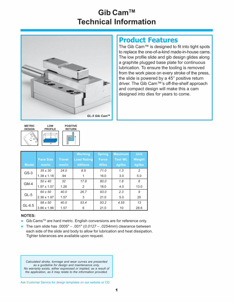
The Gib Cam™ is designed to fit into tight spotsto replace the one-of-a-kind made-in-house cams.The low profile slide and gib design glides alonga graphite plugged base plate for continuouslubrication. To ensure the tooling is removedfrom the work piece on every stroke of the press,the slide is powered by a 45° positive returndriver. The Gib Cam™’s off-the-shelf approachand compact design will make this a camdesigned into dies for years to come.
Gib CamTM
Technical Information
GL-5 Gib CamTM
Product Features
NOTES:♦ Gib CamsTM are hard metric. English conversions are for reference only.♦ The cam slide has .0005" – .001" (0.0127 – .0254mm) clearance between
each side of the slide and body to allow for lubrication and heat dissipation.Tighter tolerances are available upon request.
LOWPROFILE
POSITIVERETURN
METRICDESIGN
Calculated stroke, tonnage and wear curves are presentedas a guideline for design and maintenance only.
No warranty exists, either expressed or implied, as a result ofthe application, as it may relate to the information provided.
Working Spring Maximum UnitFace Size Travel Load Rating Force Tool Wt. Weight
Model mm/in mm/in kN/tons N/lbs kg/lbs kg/lbs
35 x 30 24.0 8.9 71.0 1.3 21.38 x 1.18 .94 1 16.0 3.0 5.0
50 x 40 32 17.8 80.0 1.8 61.97 x 1.57 1.26 2 18.0 4.0 13.0
60 x 50 40.0 26.7 93.0 2.3 92.36 x 1.97 1.57 3 21.0 5.0 20
98 x 50 40.0 53.4 93.2 4.55 133.86 x 1.96 1.57 6 21.0 10 28.6
GL-5
GM-4
GS-3
GL-6.5

2
Ask Customer Service for design templates on our website or CD.
Gib CamTM
GS-3
Gib CamsTM are hard metric.
All dimensions are for reference onlyand no tolerance is stated or implied.

3
Ask Customer Service for design templates on our website or CD.
Gib CamTM
GM-4
Gib CamsTM are hard metric.
All dimensions are for reference onlyand no tolerance is stated or implied.
4
Ask Customer Service for design templates on our website or CD.
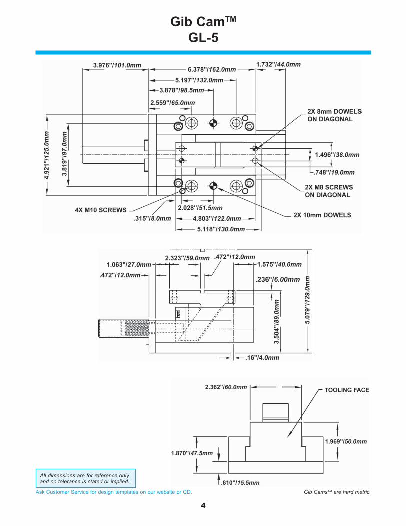
Gib CamTM
GL-5
Gib CamsTM are hard metric.
All dimensions are for reference onlyand no tolerance is stated or implied.

5
Ask Customer Service for design templates on our website or CD.
Gib CamTM
GL-6.5
Gib CamsTM are hard metric.
All dimensions are for reference onlyand no tolerance is stated or implied.
6
Ask Customer Service for design templates on our website or CD.
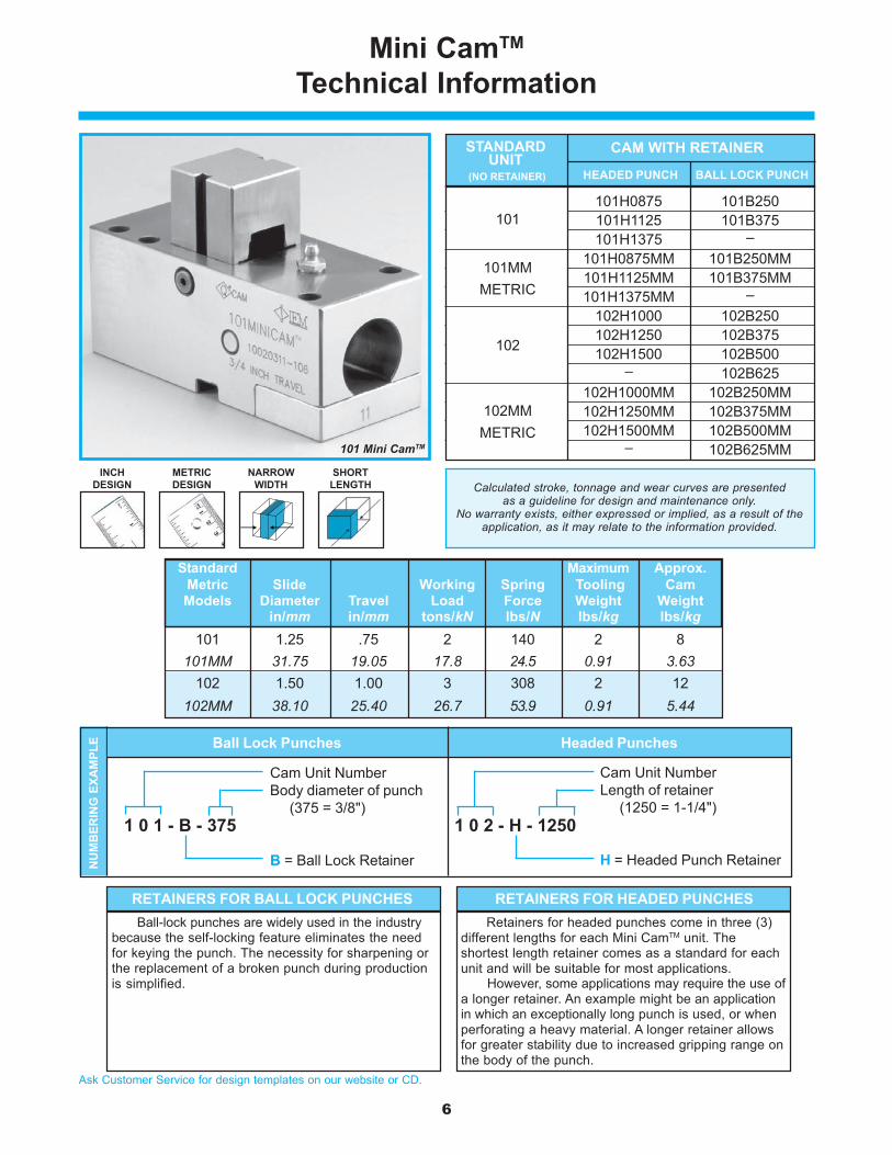
Mini CamTM
Technical Information
101 Mini CamTM
NARROWWIDTH
SHORTLENGTH
INCHDESIGN
METRICDESIGN
101 101H0875 101B250101H1125 101B375101H1375 –
101MM 101H0875MM 101B250MM101H1125MM 101B375MM101H1375MM –
102 102H1000 102B250102H1250 102B375102H1500 102B500
– 102B625102MM 102H1000MM 102B250MM
102H1250MM 102B375MM102H1500MM 102B500MM
– 102B625MM
STANDARD CAM WITH RETAINERUNIT
HEADED PUNCH BALL LOCK PUNCH
101
102
101MMMETRIC
(NO RETAINER)
102MMMETRIC
Calculated stroke, tonnage and wear curves are presentedas a guideline for design and maintenance only.
No warranty exists, either expressed or implied, as a result of theapplication, as it may relate to the information provided.
Standard Maximum Approx.Metric Slide Working Spring Tooling CamModels Diameter Travel Load Force Weight Weight
in/mm in/mm tons/kN lbs/N lbs/kg lbs/kg101 1.25 .75 2 140 2 8
101MM 31.75 19.05 17.8 24.5 0.91 3.63102 1.50 1.00 3 308 2 12
102MM 38.10 25.40 26.7 53.9 0.91 5.44
NU
MB
ERIN
G E
XAM
PLE
Cam Unit NumberBody diameter of punch (375 = 3/8")
B = Ball Lock Retainer
1 0 1 - B - 375
Ball Lock Punches
Cam Unit NumberLength of retainer (1250 = 1-1/4")
H = Headed Punch Retainer
1 0 2 - H - 1250
Headed Punches
Ball-lock punches are widely used in the industrybecause the self-locking feature eliminates the needfor keying the punch. The necessity for sharpening orthe replacement of a broken punch during productionis simplified.
RETAINERS FOR BALL LOCK PUNCHESRetainers for headed punches come in three (3)
different lengths for each Mini CamTM unit. Theshortest length retainer comes as a standard for eachunit and will be suitable for most applications.
However, some applications may require the use ofa longer retainer. An example might be an applicationin which an exceptionally long punch is used, or whenperforating a heavy material. A longer retainer allowsfor greater stability due to increased gripping range onthe body of the punch.
RETAINERS FOR HEADED PUNCHES

7
Ask Customer Service for design templates on our website or CD.
Mini CamTM
101/101MM Slide Unit
Cam models are designedin both inch and metric.
Listed dimensions may not convertdirectly into the other standard.
All dimensions are for reference onlyand no tolerance is stated or implied.
Catalog Headed Punches Light DutyNumber Shaped Round Ball Lock
with A B C Point Point PunchesRetainer in/mm in/mm in/mm in in in
101H0875 3/8 .1884 5-7/8 3/16 – 1/2 up to 1/2 –9.5 4.79 149.2
101H1125 5/8 .1884 6-1/8 3/16 – 1/2 up to 1/2 –15.9 4.79 155.6
101H1375 7/8 .1884 6-3/8 3/16 – 1/2 up to 1/2 –22.2 4.79 161.9
101B250 11/16 .2503 6-3/16 – – 1/417.5 6.36 157.2
101B375 11/16 .375 6-3/16 – – 3/817.5 9.53 157.2
Catalog Retainer HeightNumber Dimension
with DRetainer in/mm
101H0875 .875 (22.2)101H1125 1.125 (28.6)101H1375 1.375 (34.9)101B250 1.000 (25.4)101B375 1.000 (25.4)
8
Ask Customer Service for design templates on our website or CD.
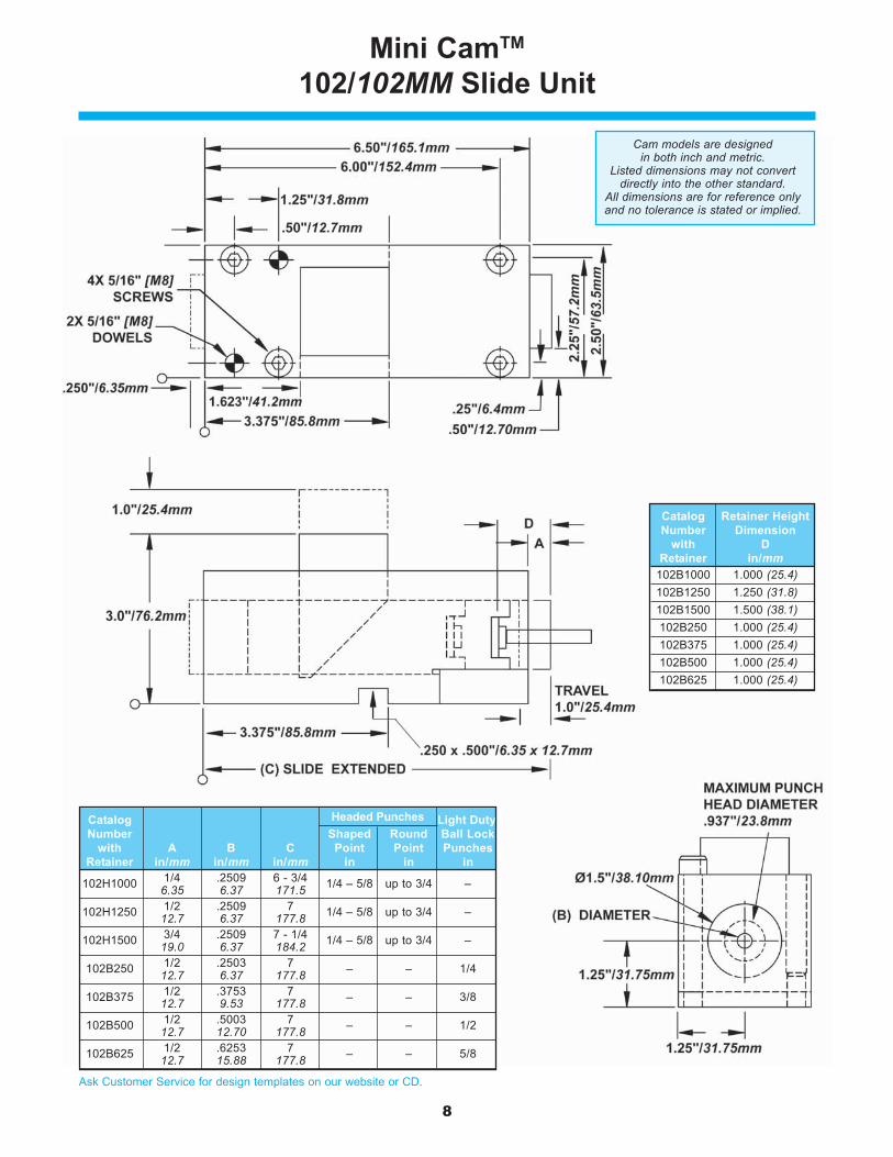
Mini CamTM
102/102MM Slide Unit
Cam models are designedin both inch and metric.
Listed dimensions may not convertdirectly into the other standard.
All dimensions are for reference onlyand no tolerance is stated or implied.
Catalog Headed Punches Light DutyNumber Shaped Round Ball Lock
with A B C Point Point PunchesRetainer in/mm in/mm in/mm in in in
102H1000 1/4 .2509 6 - 3/4 1/4 – 5/8 up to 3/4 –6.35 6.37 171.5
102H1250 1/2 .2509 7 1/4 – 5/8 up to 3/4 –12.7 6.37 177.8
102H1500 3/4 .2509 7 - 1/4 1/4 – 5/8 up to 3/4 –19.0 6.37 184.2
102B250 1/2 .2503 7 – – 1/412.7 6.37 177.8
102B375 1/2 .3753 7 – – 3/812.7 9.53 177.8
102B500 1/2 .5003 7 – – 1/212.7 12.70 177.8
102B625 1/2 .6253 7 – – 5/812.7 15.88 177.8
Catalog Retainer HeightNumber Dimension
with DRetainer in/mm
102B1000 1.000 (25.4)102B1250 1.250 (31.8)102B1500 1.500 (38.1)102B250 1.000 (25.4)102B375 1.000 (25.4)102B500 1.000 (25.4)102B625 1.000 (25.4)
9
Ask Customer Service for design templates on our website or CD.
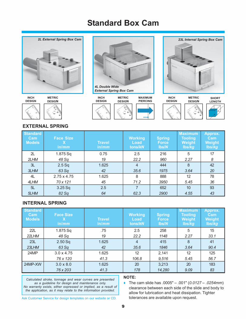
Standard Box Cam
2L External Spring Box Cam 23L Internal Spring Box Cam
4L Double WideExternal Spring Box Cam
INCHDESIGN
METRICDESIGN
SHORTLENGTH
INCHDESIGN
METRICDESIGN
EXTERNAL SPRING
INCHDESIGN
METRICDESIGN
MAXIMUMPIERCING
NOTE:♦ The cam slide has .0005" – .001" (0.0127 – .0254mm)
clearance between each side of the slide and body toallow for lubrication and heat dissipation. Tightertolerances are available upon request.
INTERNAL SPRINGStandard Maximum Approx.
Cam Face Size Working Spring Tooling CamModels X Travel Load Force Weight Weight
in/mm in/mm tons/kN lbs/N lbs/kg lbs/kg22L 1.875 Sq .75 2.5 258 5 15
22LHM 48 Sq 19 22.2 1148 2.27 33.123L 2.50 Sq 1.625 4 415 8 41
23LHM 63 Sq 42 35.6 1846 3.64 90.424MP 3.0 x 4.75 1.625 12 2,141 12 125
76 x 120 41.3 106.8 9,516 5.45 56.724MP-XW 3.0 x 8.0 1.625 20 3,213 20 183
76 x 203 41.3 178 14,280 9.09 83
Standard Maximum Approx.Cam Face Size Working Spring Tooling Cam
Models X Travel Load Force Weight Weightin/mm in/mm tons/kN lbs/N lbs/kg lbs/kg
2L 1.875 Sq 0.75 2.5 216 5 172LHM 48 Sq 19 22.2 960 2.27 8
3L 2.5 Sq 1.625 4 444 8 423LHM 63 Sq 42 35.6 1975 3.64 20
4L 2.75 x 4.75 1.625 8 888 12 784LHM 70 x 121 45 71.2 3950 5.45 36
5L 3.25 Sq 2.5 7 652 10 935LHM 82 Sq 64 62.3 2900 4.55 43
Calculated stroke, tonnage and wear curves are presentedas a guideline for design and maintenance only.
No warranty exists, either expressed or implied, as a result ofthe application, as it may relate to the information provided.
10
Ask Customer Service for design templates on our website or CD.
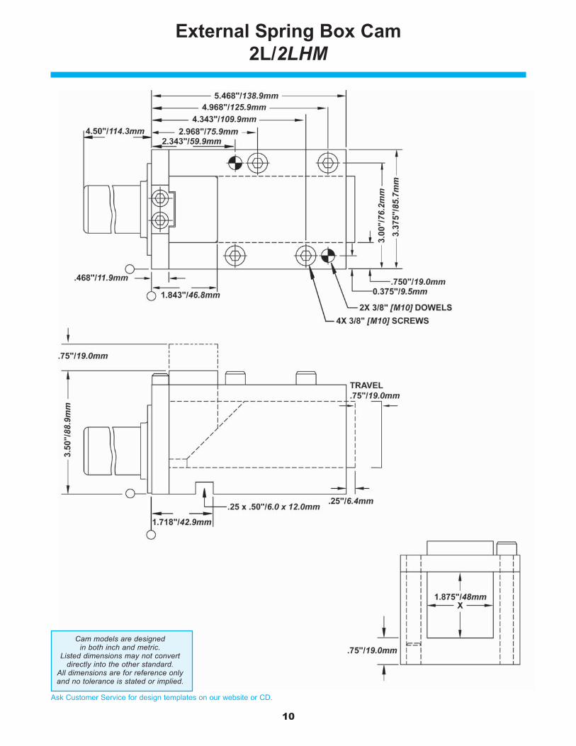
External Spring Box Cam2L/2LHM
Cam models are designedin both inch and metric.
Listed dimensions may not convertdirectly into the other standard.
All dimensions are for reference onlyand no tolerance is stated or implied.

11
Ask Customer Service for design templates on our website or CD.
External Spring Box Cam3L/3LHM
Cam models are designedin both inch and metric.
Listed dimensions may not convertdirectly into the other standard.
All dimensions are for reference onlyand no tolerance is stated or implied.
12
Ask Customer Service for design templates on our website or CD.
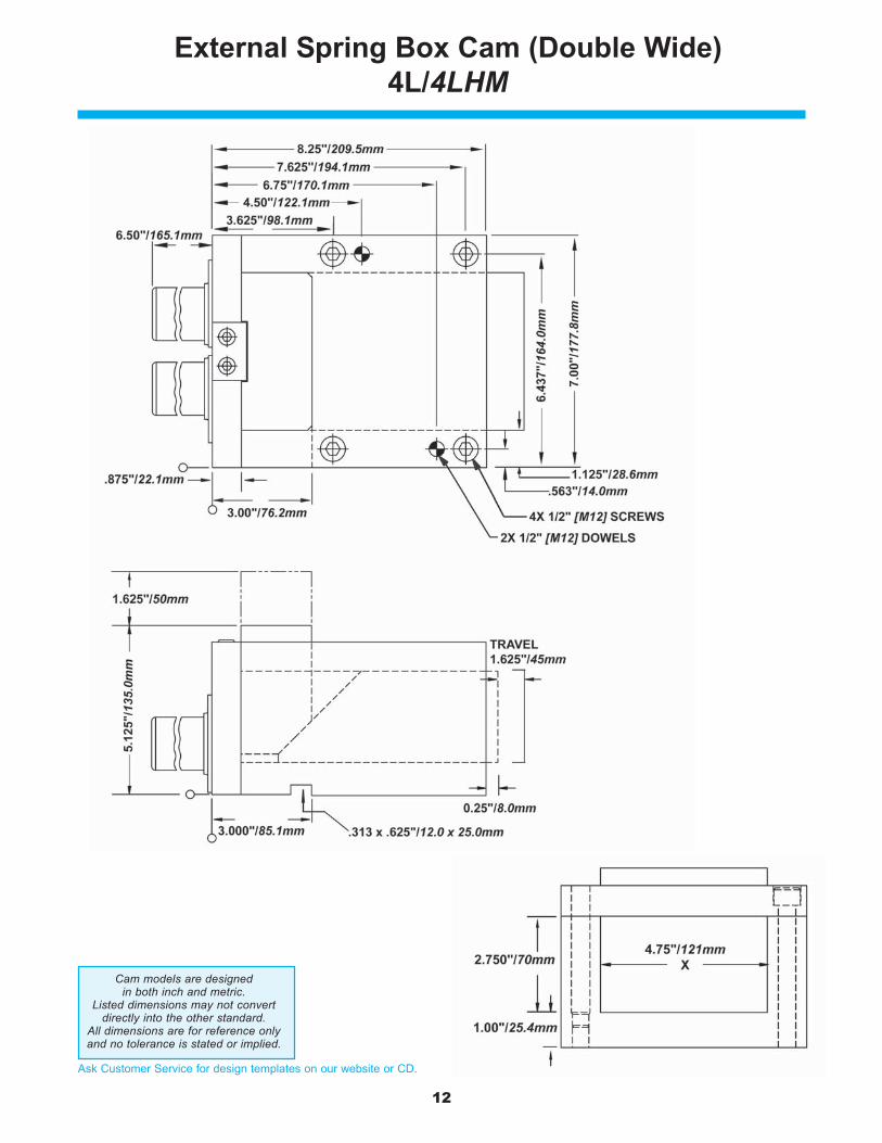
External Spring Box Cam (Double Wide)4L/4LHM
Cam models are designedin both inch and metric.
Listed dimensions may not convertdirectly into the other standard.
All dimensions are for reference onlyand no tolerance is stated or implied.
13
Ask Customer Service for design templates on our website or CD.
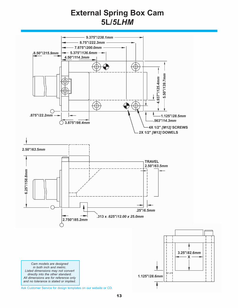
External Spring Box Cam5L/5LHM
Cam models are designedin both inch and metric.
Listed dimensions may not convertdirectly into the other standard.
All dimensions are for reference onlyand no tolerance is stated or implied.

14
Ask Customer Service for design templates on our website or CD.
Internal Spring Box Cam22L/22LMM
Cam models are designedin both inch and metric.
Listed dimensions may not convertdirectly into the other standard.
All dimensions are for reference onlyand no tolerance is stated or implied.
15
Ask Customer Service for design templates on our website or CD.
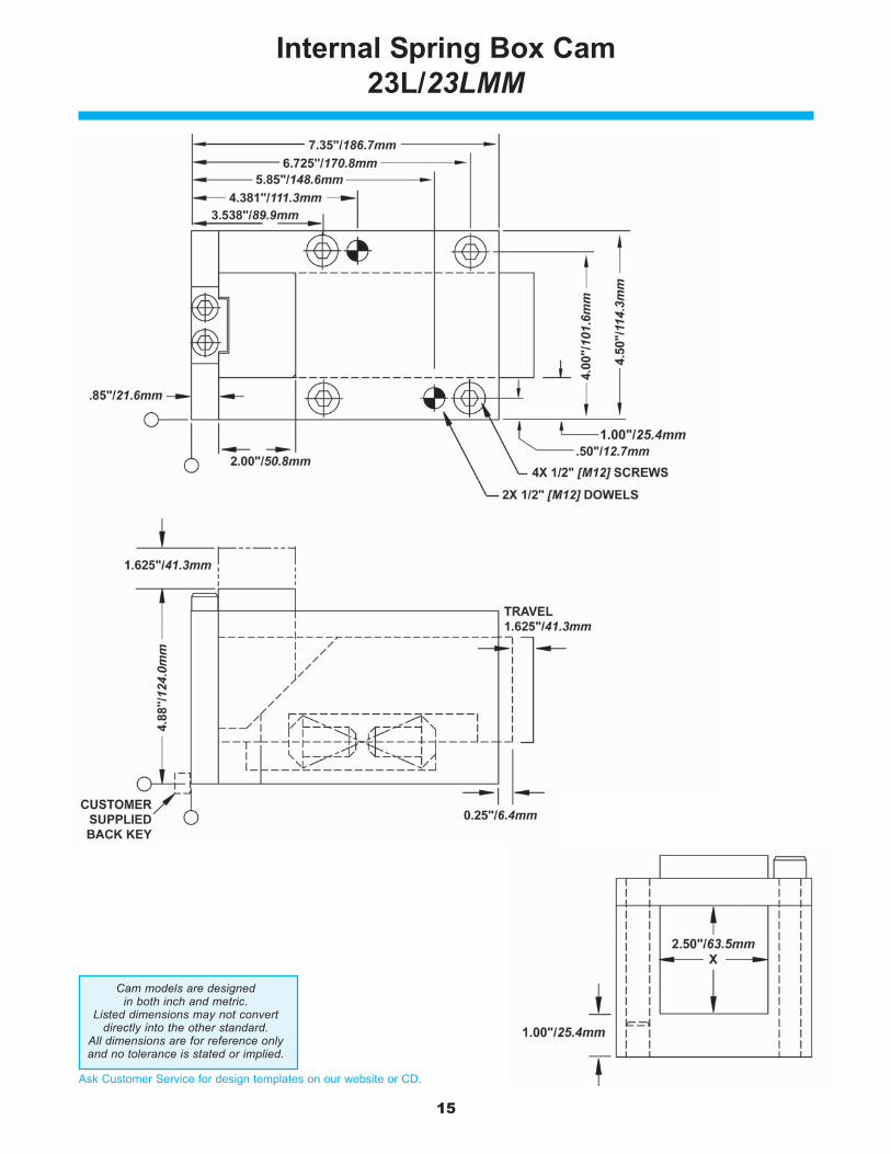
Internal Spring Box Cam23L/23LMM
Cam models are designedin both inch and metric.
Listed dimensions may not convertdirectly into the other standard.
All dimensions are for reference onlyand no tolerance is stated or implied.
16
Ask Customer Service for design templates on our website or CD.
INCHDESIGN
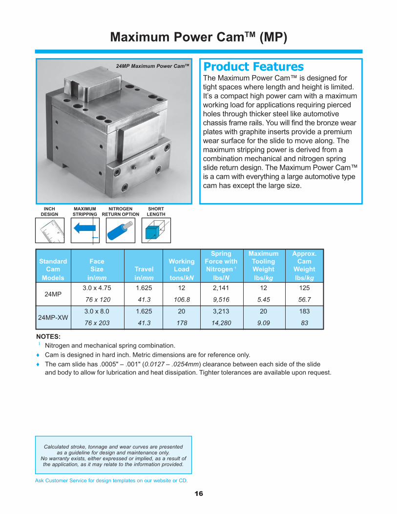
24MP Maximum Power CamTM
MAXIMUMSTRIPPING
SHORTLENGTH
NITROGENRETURN OPTION
Maximum Power CamTM (MP)
Spring Maximum Approx.Standard Face Working Force with Tooling Cam
Cam Size Travel Load Nitrogen 1 Weight WeightModels in/mm in/mm tons/kN lbs/N lbs/kg lbs/kg
24MP3.0 x 4.75 1.625 12 2,141 12 125
76 x 120 41.3 106.8 9,516 5.45 56.7
24MP-XW3.0 x 8.0 1.625 20 3,213 20 183
76 x 203 41.3 178 14,280 9.09 83
The Maximum Power Cam™ is designed fortight spaces where length and height is limited.It’s a compact high power cam with a maximumworking load for applications requiring piercedholes through thicker steel like automotivechassis frame rails. You will find the bronze wearplates with graphite inserts provide a premiumwear surface for the slide to move along. Themaximum stripping power is derived from acombination mechanical and nitrogen springslide return design. The Maximum Power Cam™is a cam with everything a large automotive typecam has except the large size.
Product Features
NOTES: 1 Nitrogen and mechanical spring combination.♦ Cam is designed in hard inch. Metric dimensions are for reference only.♦ The cam slide has .0005" – .001" (0.0127 – .0254mm) clearance between each side of the slide
and body to allow for lubrication and heat dissipation. Tighter tolerances are available upon request.
Calculated stroke, tonnage and wear curves are presentedas a guideline for design and maintenance only.
No warranty exists, either expressed or implied, as a result ofthe application, as it may relate to the information provided.
17
Ask Customer Service for design templates on our website or CD.
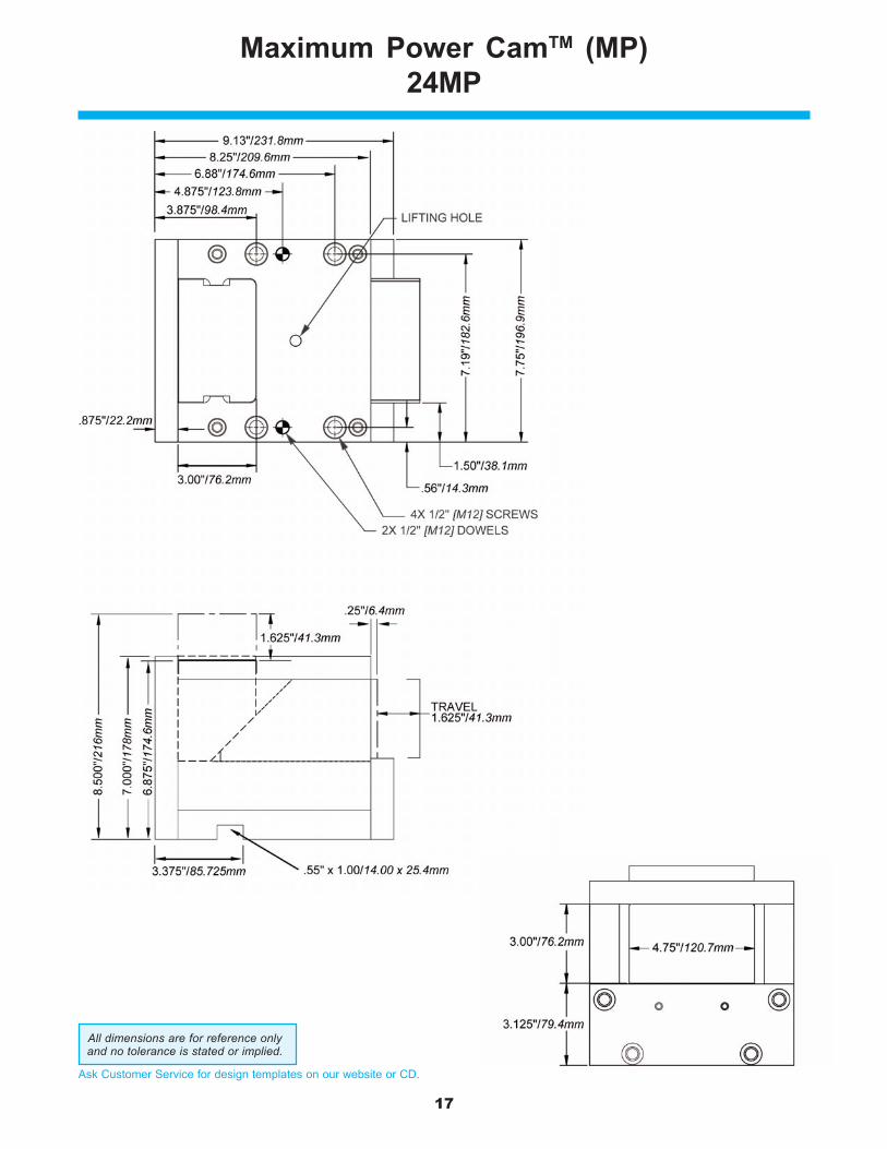
Maximum Power CamTM (MP)24MP
All dimensions are for reference onlyand no tolerance is stated or implied.
18
Ask Customer Service for design templates on our website or CD.
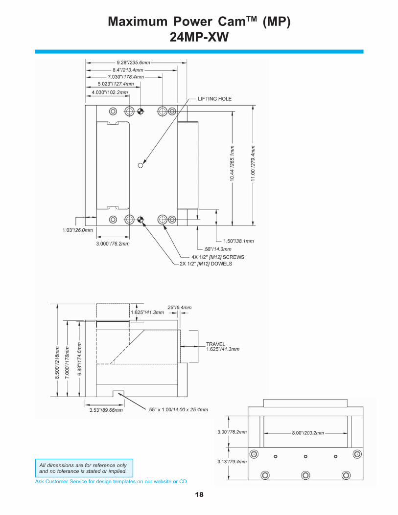
Maximum Power CamTM (MP)24MP-XW
All dimensions are for reference onlyand no tolerance is stated or implied.
19
Ask Customer Service for design templates on our website or CD.
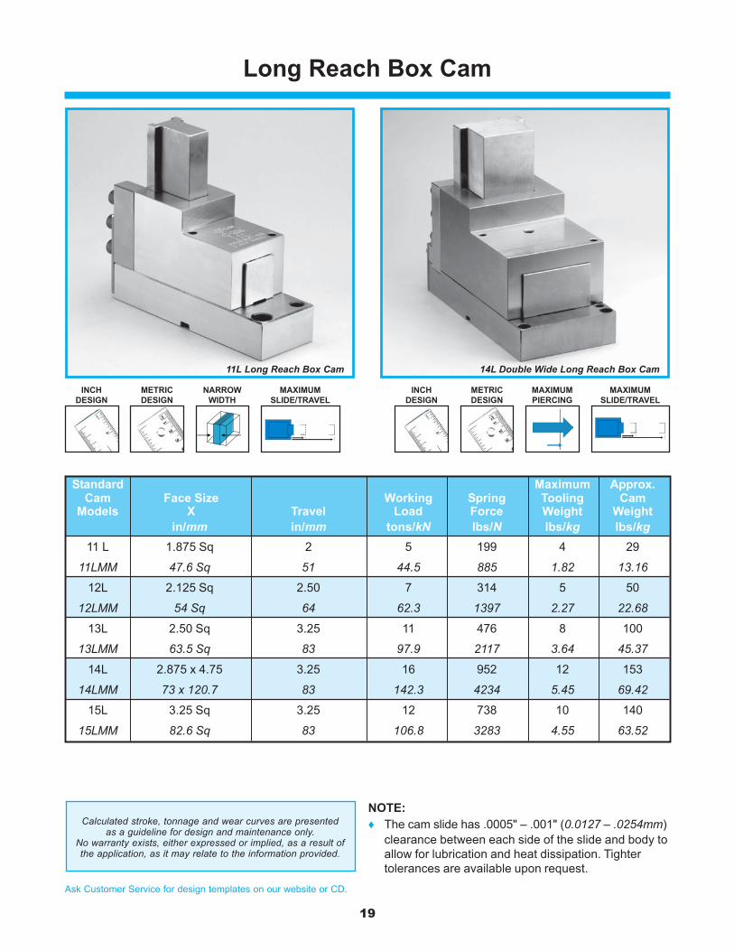
Long Reach Box Cam
11L Long Reach Box Cam 14L Double Wide Long Reach Box Cam
NARROWWIDTH
MAXIMUMSLIDE/TRAVEL
METRICDESIGN
MAXIMUMPIERCING
MAXIMUMSLIDE/TRAVEL
INCHDESIGN
METRICDESIGN
INCHDESIGN
Calculated stroke, tonnage and wear curves are presentedas a guideline for design and maintenance only.
No warranty exists, either expressed or implied, as a result ofthe application, as it may relate to the information provided.
NOTE:♦ The cam slide has .0005" – .001" (0.0127 – .0254mm)
clearance between each side of the slide and body toallow for lubrication and heat dissipation. Tightertolerances are available upon request.
Standard Maximum Approx.Cam Face Size Working Spring Tooling Cam
Models X Travel Load Force Weight Weightin/mm in/mm tons/kN lbs/N lbs/kg lbs/kg
11 L 1.875 Sq 2 5 199 4 29
11LMM 47.6 Sq 51 44.5 885 1.82 13.16
12L 2.125 Sq 2.50 7 314 5 50
12LMM 54 Sq 64 62.3 1397 2.27 22.68
13L 2.50 Sq 3.25 11 476 8 100
13LMM 63.5 Sq 83 97.9 2117 3.64 45.37
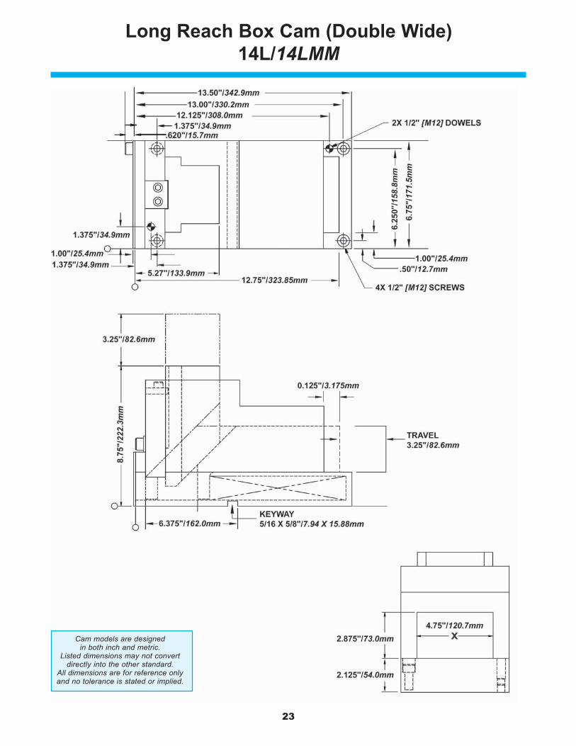
14L 2.875 x 4.75 3.25 16 952 12 153
14LMM 73 x 120.7 83 142.3 4234 5.45 69.42
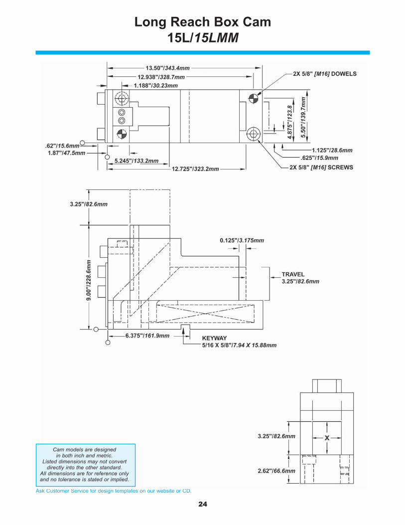
15L 3.25 Sq 3.25 12 738 10 140
15LMM 82.6 Sq 83 106.8 3283 4.55 63.52
20
Ask Customer Service for design templates on our website or CD.
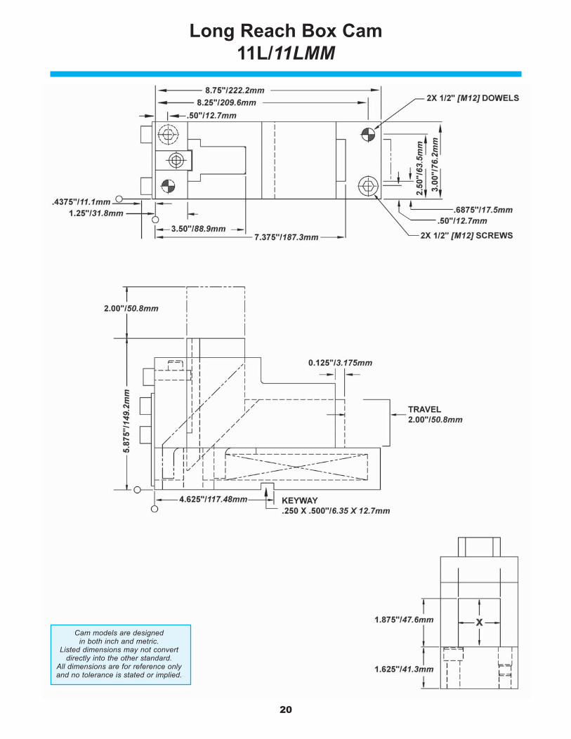
Long Reach Box Cam11L/11LMM
Cam models are designedin both inch and metric.
Listed dimensions may not convertdirectly into the other standard.
All dimensions are for reference onlyand no tolerance is stated or implied.
21
Ask Customer Service for design templates on our website or CD.
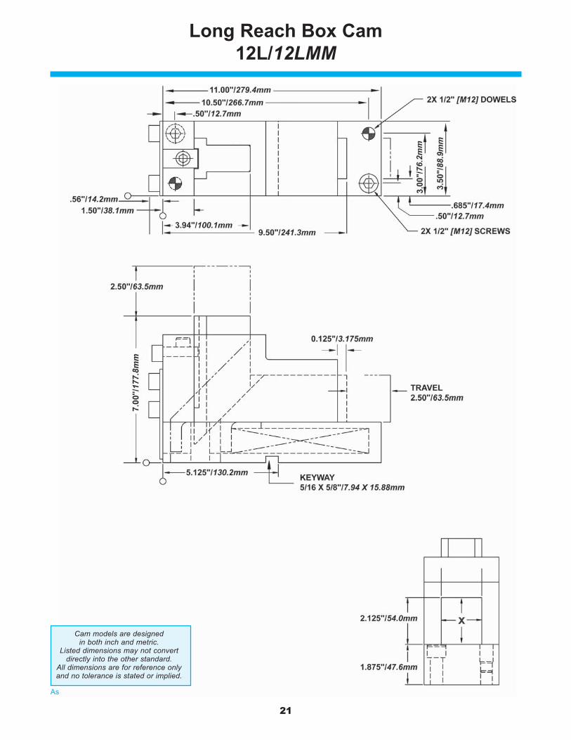
Long Reach Box Cam12L/12LMM
Cam models are designedin both inch and metric.
Listed dimensions may not convertdirectly into the other standard.
All dimensions are for reference onlyand no tolerance is stated or implied.
22
Ask Customer Service for design templates on our website or CD.
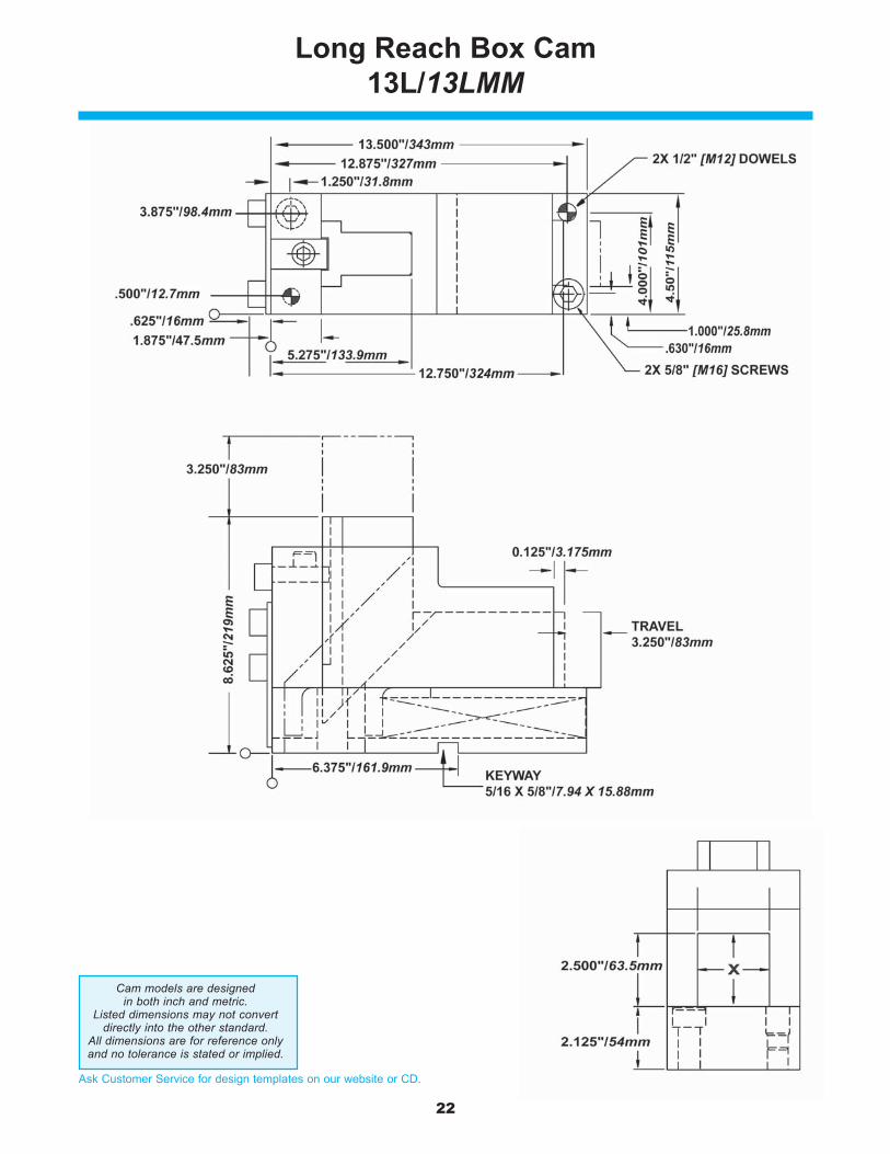
Long Reach Box Cam13L/13LMM
Cam models are designedin both inch and metric.
Listed dimensions may not convertdirectly into the other standard.
All dimensions are for reference onlyand no tolerance is stated or implied.
23
Ask Customer Service for design templates on our website or CD.
Long Reach Box Cam (Double Wide)14L/14LMM
Cam models are designedin both inch and metric.
Listed dimensions may not convertdirectly into the other standard.
All dimensions are for reference onlyand no tolerance is stated or implied.
24
Ask Customer Service for design templates on our website or CD.
Long Reach Box Cam15L/15LMM
Cam models are designedin both inch and metric.
Listed dimensions may not convertdirectly into the other standard.
All dimensions are for reference onlyand no tolerance is stated or implied.
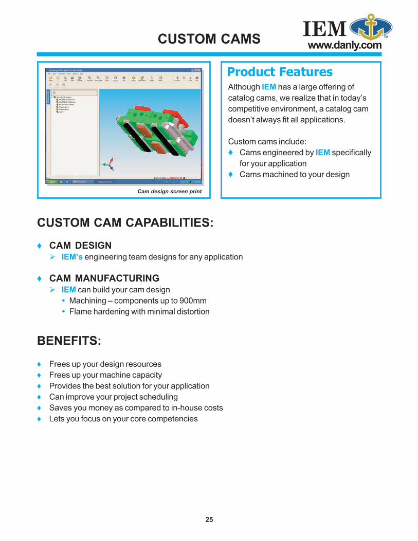
IEMwww.danly.comCUSTOM CAMS
Although IEM has a large offering ofcatalog cams, we realize that in today’scompetitive environment, a catalog camdoesn’t always fit all applications.
Custom cams include:♦ Cams engineered by IEM specifically
for your application♦ Cams machined to your design
CUSTOM CAM CAPABILITIES:
♦ CAM DESIGNIEM’s engineering team designs for any application
♦ CAM MANUFACTURINGIEM can build your cam design
Machining – components up to 900mmFlame hardening with minimal distortion
BENEFITS:
♦ Frees up your design resources♦ Frees up your machine capacity♦ Provides the best solution for your application♦ Can improve your project scheduling♦ Saves you money as compared to in-house costs♦ Lets you focus on your core competencies
25
Cam design screen print
Product Features
IEMwww.danly.com
CAM CATALOG
DS 401-1 09/08© 2008 IEM. All rights reserved.
Distributed by:
WITHIN THE USA & CANADACALL: 800-243-2659FAX: 800-833-2659
OUTSIDE THE USA & CANADACALL: 001-248-489-7816FAX: 001-248-553-6842
IEM