iem aerial and die mount cams catalog - anchor danly · iem aerial & die mount cams service we...
TRANSCRIPT

IEMwww.danly.com
AERIAL & DIE MOUNTCAMS CATALOG
AERIAL & DIE MOUNTAERIAL & DIE MOUNTCAMS CATALOGCAMS CATALOG
TRUSTED SOLUTIONS AND INNOVATION
IEMIEM
IEMwww.danly.com
AERIAL & DIE MOUNT CAMS
SERVICE WE DELIVER AND QUALITY YOU CAN DEPEND ON
IEM is a leading manufacturer of die sets and die component products supplied globally to the parts forming industry.Backed by years of tool and die experience, quality and innovation are some of the reasons why our name is respectedthroughout the world. We have taken the lead role in creating and bringing new products to customers and helpingthem find solutions that improve their operations. Based on the capabilities IEM offers, we can help you to meetthe demands of quick deliveries, technical support, quality products and competitive prices. IEM and its’ broaddistribution channels and direct sales personnel will assist you in any way to make your product a better and moreprofitable one.
Whether standard or customized products, with our years of experience, customers can be sure the products theyreceive will meet their expectations for reliability and dependable performance. We understand the demanding schedulesof die builders and production personnel and have developed efficient manufacturing processes to shorten productlead times as well as put inventory on our shelves so you can have it in your facility when you need it. Put the IEMnetwork to work for you. We’ve got the service you’ve been looking for.
Included in our full line offering are both inch and metric size die sets and die components that are designed tonumerous die standards including ISO, NAAMS, JIS and many large automotive and appliance manufacturers’standards. The complete product offering includes:
Accu-BendTM Rotary BendersAir PressesCams• Aerial and Diemount Cams• Box Cams• Roller Cams• Wide CamsDie AccessoriesDie Sets• Plain and Ball Bearing Sets• Catalog Ball Bearing Sets• Wear Plate Sets• Cast SetsEjector BoxesGuide Posts and Bushings• Plain and Ball Bearing Styles• Steel, Bronze, Bronze-Plated and
Self-Lubricating Bushings• Lempcoloy® Bushings• Special Pins, Bushings and RetainersHydraulics• Electronic Die Setters• Die Separators• Drill and Tap Equipment• Hydraulic MotorsIn-Die Tapping UnitsMachined and Cut Ground Plate• Adapter Plates• Bolster Plates• 1020, 1045 & 4140 Materials
Manufacturing Services• CNC Machining• Blanchard Grinding• Stress Relieving• Die Set RepairMold Components• Bronze-Plated and Self-Lubricated Bushings• Leader Pins• Bronze and Bronze-Plated Wear Strips and WaysPunches, Buttons & RetainersReliance Fabrications• Custom Fabrications• Robotic Welding• Aluminum and Steel Fixture BasesSprings• DieMaxTM L Inch Series Springs• DieMax XLTM Series ISO Springs• JIS Series Springs• Custom Heavy Duty Springs• Marsh Mellow® Springs• Formathane® Urethane• Kaller Gas Springs• Utility and Disc SpringsWear Products• Plates, Strips, Gibs and Blocks• Steel, Bronze, Bronze-Plated and
Self-Lubricating Materials

1
Ask Customer Service for design templates on our website or CD. All dimensions are for reference only.Picture not representative of all angles. No tolerance is stated or implied.
CONTENTS
Cam Selection Matrix 2
General Information 3
NAAMS Standards Aerial Cams50 mm 475 mm 6125 mm 8150 mm 10175 mm 12200 mm 14250 mm 16300 mm 18
NAAMS Standards Die Mount Cams50 mm 2075 mm 22150 mm 24200 mm 26250 mm 28300 mm 33
Long Reaching (Extra Travel)Die Mount Cams (LRD)When to Use a LRD Cam 3375 mm 34150 mm 36200 mm 38
Calculation of Load and Stroke 40
PAGE NUMBER

2
Ask Customer Service for design templates on our website or CD. All dimensions are for reference only.Picture not representative of all angles. No tolerance is stated or implied.
Cam Selection Matrix
Nitrogen Return Option – Using nitrogen springs to replace thestandard mechanical springs will provide more slide return force for applicationsinvolving heavier tooling mounted on the slide face. Individual return forcescan be found on the specifications table for each size cam.
Positive Return – Included are mechanical return straps designedinto the cam to pull the slide and tooling out of the part in case of a toolingjam. Positive return straps are designed to provide a positive return but arenot designed to provide continuous stripping force.
Electronic Templates Available – Each cam has Template orModel files online for easy download into your die designs. The slide, body anddriver are broken into three components for die movement simulation. Theformats available are 2D/3D DWG, IGES, STEP, Parasolid, Catia, andSolidworks.
Special Cam Designs – We know there are sometimes when astandard cam doesn't fit into an application or is at the wrong angle. If youprovide us with your application specifications, we will design and build aspecial cam for you.
Items inthe blueshadedarea areincludedin this
catalog.
Gib
TM
Min
iTM
Long
Rea
ch B
ox
(Ext
ra Tr
avel
)St
anda
rd B
oxM
ax P
ower
TMBo
x (M
P)M
ilfab
®
NDM
Die
Mou
nts
NAC
Aeria
lLo
ng R
each
ing
(Ext
ra Tr
avel
)
Die
Mou
nt
NAAMSStandards
Inch X X X XMetric X X X X X X X X XLow profile X XNarrow width X X XShort length X X X XMaximumslide travel X XMaximumstripping force X XNitrogen Return X X X X XPositive return X X X X XMaximumpiercing force X X X X XDesigned toNAAMS Standards X XSpecial CamDesigns Available X X X X X X X X X
S

3
Ask Customer Service for design templates on our website or CD. All dimensions are for reference only.Picture not representative of all angles. No tolerance is stated or implied.
Product Information
Every NAAMS cam provides excellentperformance and is designed with heavy-dutyhigh volume production in mind.
♦ Self lubricating sliding surfaces providemaintenance free operation.
♦ Aluminum Bronze against steel wear surfacesis standard with an option of steel on steelwear surfaces.
♦ Slide accelerators are added to certain anglesfor quiet operation & reduced wear.
♦ Positive return(s) on the cam slide assuresslide retraction and extra protection.
♦ Ease of setup with home position slide lockoutcapabilities.
♦ Rear spring access for ease of maintenance.
♦ Quick slide removal with top access keeperplate for all die mount cams.
Product Features
NAC075-20NAAMS
Aerial Cam
NDM075-00NAAMS
Die Mount Cam

4
Ask Customer Service for design templates on our website or CD. All dimensions are for reference only.Picture not representative of all angles. No tolerance is stated or implied.
Aerial Cam – 50 mm
TOP VIEW
909
0 13 212
2X ø12 DOWELS
2X M12 MOUNTINGSCREWS
80 12
SIDE VIEW
Z
2X ø12 DOWELS
012
.5
909
BOTTOM VIEW (Driver Only)
2X M12 MOUNTINGSCREWS
225
E
C N
225 SLIDETRAVEL
WORKTRAVEL
WORKANGLE
A
67
94.1MAX.
H P
D
Y
5080
TOOLINGFACE CL
TOOLINGBALL CL
TOOLING MOUNTING FACE
CUSTOMER SUPPLIEDBACK KEY
REF.
Ø12
12
NAAMS TOOLING BALL
J
PRESS TRAVEL
SLIDETRAVEL
30 mm
WORKTRAVEL WORK
ANGLE
ADAPTERANGLE
CAM MOTION
Tooling ball located at “A” dimension per NAAMS.“Y” dimension represents the tooling ball from the slide centerline.
Dowel holes undersized 0.2/0.3mm.
0 - 15° 147.520 - 60° 127.5
WORKANGLE Z
Tooling ball is not suppliedwith the cam and is
a reference point only.
5
Ask Customer Service for design templates on our website or CD. All dimensions are for reference only.Picture not representative of all angles. No tolerance is stated or implied.
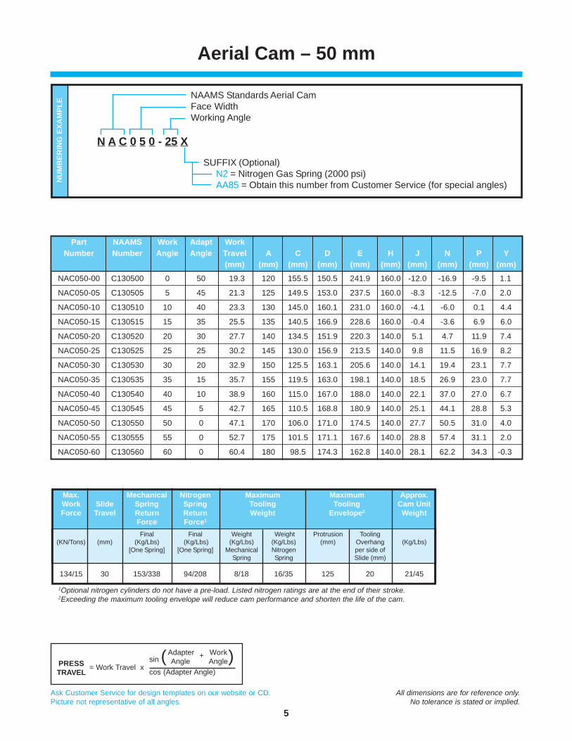
Aerial Cam – 50 mm
NAAMS Standards Aerial CamFace WidthWorking Angle
SUFFIX (Optional)N2 = Nitrogen Gas Spring (2000 psi)AA85 = Obtain this number from Customer Service (for special angles)
N A C 0 5 0 - 25 X
NU
MB
ERIN
G E
XAM
PLE
1Optional nitrogen cylinders do not have a pre-load. Listed nitrogen ratings are at the end of their stroke.2Exceeding the maximum tooling envelope will reduce cam performance and shorten the life of the cam.
Max. Mechanical Nitrogen Maximum Maximum Approx.Work Slide Spring Spring Tooling Tooling Cam UnitForce Travel Return Return Weight Envelope2 Weight
Force Force1
Final Final Weight Weight Protrusion Tooling(KN/Tons) (mm) (Kg/Lbs) (Kg/Lbs) (Kg/Lbs) (Kg/Lbs) (mm) Overhang (Kg/Lbs)
[One Spring] [One Spring] Mechanical Nitrogen per side ofSpring Spring Slide (mm)
134/15 30 153/338 94/208 8/18 16/35 125 20 21/45
Part NAAMS Work Adapt WorkNumber Number Angle Angle Travel A C D E H J N P Y
(mm) (mm) (mm) (mm) (mm) (mm) (mm) (mm) (mm) (mm)
NAC050-00 C130500 0 50 19.3 120 155.5 150.5 241.9 160.0 -12.0 -16.9 -9.5 1.1
NAC050-05 C130505 5 45 21.3 125 149.5 153.0 237.5 160.0 -8.3 -12.5 -7.0 2.0
NAC050-10 C130510 10 40 23.3 130 145.0 160.1 231.0 160.0 -4.1 -6.0 0.1 4.4
NAC050-15 C130515 15 35 25.5 135 140.5 166.9 228.6 160.0 -0.4 -3.6 6.9 6.0
NAC050-20 C130520 20 30 27.7 140 134.5 151.9 220.3 140.0 5.1 4.7 11.9 7.4
NAC050-25 C130525 25 25 30.2 145 130.0 156.9 213.5 140.0 9.8 11.5 16.9 8.2
NAC050-30 C130530 30 20 32.9 150 125.5 163.1 205.6 140.0 14.1 19.4 23.1 7.7
NAC050-35 C130535 35 15 35.7 155 119.5 163.0 198.1 140.0 18.5 26.9 23.0 7.7
NAC050-40 C130540 40 10 38.9 160 115.0 167.0 188.0 140.0 22.1 37.0 27.0 6.7
NAC050-45 C130545 45 5 42.7 165 110.5 168.8 180.9 140.0 25.1 44.1 28.8 5.3
NAC050-50 C130550 50 0 47.1 170 106.0 171.0 174.5 140.0 27.7 50.5 31.0 4.0
NAC050-55 C130555 55 0 52.7 175 101.5 171.1 167.6 140.0 28.8 57.4 31.1 2.0
NAC050-60 C130560 60 0 60.4 180 98.5 174.3 162.8 140.0 28.1 62.2 34.3 -0.3
PRESSTRAVEL = Work Travel x
sin ( )cos (Adapter Angle)
Adapter + WorkAngle Angle

6
Ask Customer Service for design templates on our website or CD. All dimensions are for reference only.Picture not representative of all angles. No tolerance is stated or implied.
0 15 180
2X ø12 DOWELS
BOTTOM VIEW (Driver Only)
4X M12 MOUNTINGSCREWS
SIDE VIEW
115
12
CUSTOMER SUPPLIEDBACK KEY
REF.
WORKANGLE
195
D
P
102 154.3MAX.
75
95
TOOLING MOUNTING FACE
Y
WORKTRAVEL
J
A
N
GE
C
SLIDETRAVEL275
TOOLINGFACE CL
TOOLINGBALL CL
0 1845
0
45
2X ø12 DOWELS
4X M12 MOUNTINGSCREWS
TOP VIEW
Q
48
Ø12
12
NAAMS TOOLING BALL
Z
0
Z
PRESS TRAVEL
SLIDETRAVEL
50 mm
WORKTRAVEL WORK
ANGLE
ADAPTERANGLE
CAM MOTION
0° 272 18.55° 282 18.5
10° 292 18.515° 287 18.520° 292 22.525° 282 22.530° 292 22.535° 287 22.540° 287 22.545° 287 22.550° 277 22.555° 277 22.560° 277 22.5
WORKANGLE Q Z
Aerial CAM – 75 mm
Tooling ball located at “A” dimension per NAAMS.“Y” dimension represents the tooling ball from the slide centerline.
Dowel holes undersized 0.2/0.3mm.
Tooling ball is not suppliedwith the cam and is
a reference point only.

7
Ask Customer Service for design templates on our website or CD. All dimensions are for reference only.Picture not representative of all angles. No tolerance is stated or implied.
Aerial CAM – 75 mm
NAAMS Standards Aerial CamFace WidthWorking Angle
SUFFIX (Optional)N2 = Nitrogen Gas Spring (2000 psi)AA85 = Obtain this number from Customer Service (for special angles)
N A C 0 7 5 - 25 X
NU
MB
ERIN
G E
XAM
PLE
1Optional nitrogen cylinders do not have a pre-load. Listed nitrogen ratings are at the end of their stroke.2Exceeding the maximum tooling envelope will reduce cam performance and shorten the life of the cam.
Max. Mechanical Nitrogen Maximum Maximum Approx.Work Slide Spring Spring Tooling Tooling Cam UnitForce Travel Return Return Weight Envelope2 Weight
Force Force1
Final Final Weight Weight Protrusion Tooling(KN/Tons) (mm) (Kg/Lbs) (Kg/Lbs) (Kg/Lbs) (Kg/Lbs) (mm) Overhang (Kg/Lbs)
[One Spring] [One Spring] Mechanical Nitrogen per side ofSpring Spring Slide (mm)
134/15 50 220/485 316/697 12/26 24/53 140 20 46/100
Part NAAMS Work Adapt WorkNumber Number Angle Angle Travel A C D E G J N P Y
(mm) (mm) (mm) (mm) (mm) (mm) (mm) (mm) (mm) (mm)
NAC075-00 C130700 0 50 32.1 155 180.0 210.1 330.0 290 -12.0 -40.0 15.1 15.0
NAC075-05 C130705 5 45 35.5 160 160.5 217.5 330.2 300 -6.6 -30.2 22.5 14.4
NAC075-10 C130710 10 40 38.9 165 153.0 224.7 330.4 310 -1.3 -20.4 29.7 13.2
NAC075-15 C130715 15 35 42.4 170 144.0 230.9 320.0 305 4.3 -15.0 35.9 13.9
NAC075-20 C130720 20 30 46.1 175 136.5 237.6 315.0 310 8.9 -5.0 42.6 11.5
NAC075-25 C130725 25 25 50.0 180 127.5 246.6 300.0 300 10.4 0.0 51.6 2.8
NAC075-30 C130730 30 20 54.3 185 120.0 254.0 300.0 310 12.6 10.0 59.0 -1.5
NAC075-35 C130735 35 15 59.0 190 112.5 261.8 285.0 305 13.6 20.0 66.8 -6.7
NAC075-40 C130740 40 10 64.3 195 105.0 270.4 275.0 305 12.9 30.0 75.4 -13.2
NAC075-45 C130745 45 5 70.4 200 99.0 274.9 265.0 305 15.1 40.0 79.9 -14.1
NAC075-50 C130750 50 0 77.8 205 93.0 278.6 263.6 295 17.2 31.4 83.6 -15.0
NAC075-55 C130755 55 0 87.2 210 72.0 267.5 240.9 295 33.8 54.1 72.5 2.2
NAC075-60 C130760 60 0 100.0 215 79.0 282.0 246.8 295 24.9 48.2 87.0 -11.8
PRESSTRAVEL = Work Travel x
sin ( )cos (Adapter Angle)
Adapter + WorkAngle Angle
8
Ask Customer Service for design templates on our website or CD. All dimensions are for reference only.Picture not representative of all angles. No tolerance is stated or implied.
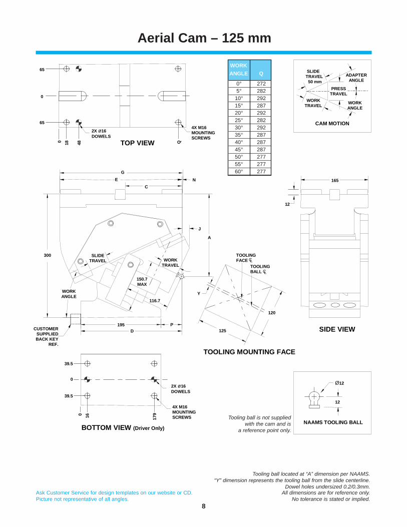
Aerial Cam – 125 mm
BOTTOM VIEW (Driver Only)
39.5
0
39.5
4X M16 MOUNTINGSCREWS
2X ø16 DOWELS
0 16 179
0 18 48
12
165
SIDE VIEW
TOOLING MOUNTING FACE
CUSTOMERSUPPLIEDBACK KEY
REF.
WORK ANGLE
150.7MAX
195D
P
116.7
WORKTRAVEL
125
120
Y
A
J
300 SLIDETRAVEL
N
GE
C
TOOLINGFACE CL
TOOLINGBALL CL
2X ø16 DOWELS
4X M16 MOUNTINGSCREWS
Q
65
0
65
TOP VIEW
PRESS TRAVEL
SLIDETRAVEL
50 mm
WORKTRAVEL WORK
ANGLE
ADAPTERANGLE
CAM MOTION
Ø12
12
NAAMS TOOLING BALL
0° 2725° 282
10° 29215° 28720° 29225° 28230° 29235° 28740° 28745° 28750° 27755° 27760° 277
WORKANGLE Q
Tooling ball located at “A” dimension per NAAMS.“Y” dimension represents the tooling ball from the slide centerline.
Dowel holes undersized 0.2/0.3mm.
Tooling ball is not suppliedwith the cam and is
a reference point only.
9
Ask Customer Service for design templates on our website or CD. All dimensions are for reference only.Picture not representative of all angles. No tolerance is stated or implied.
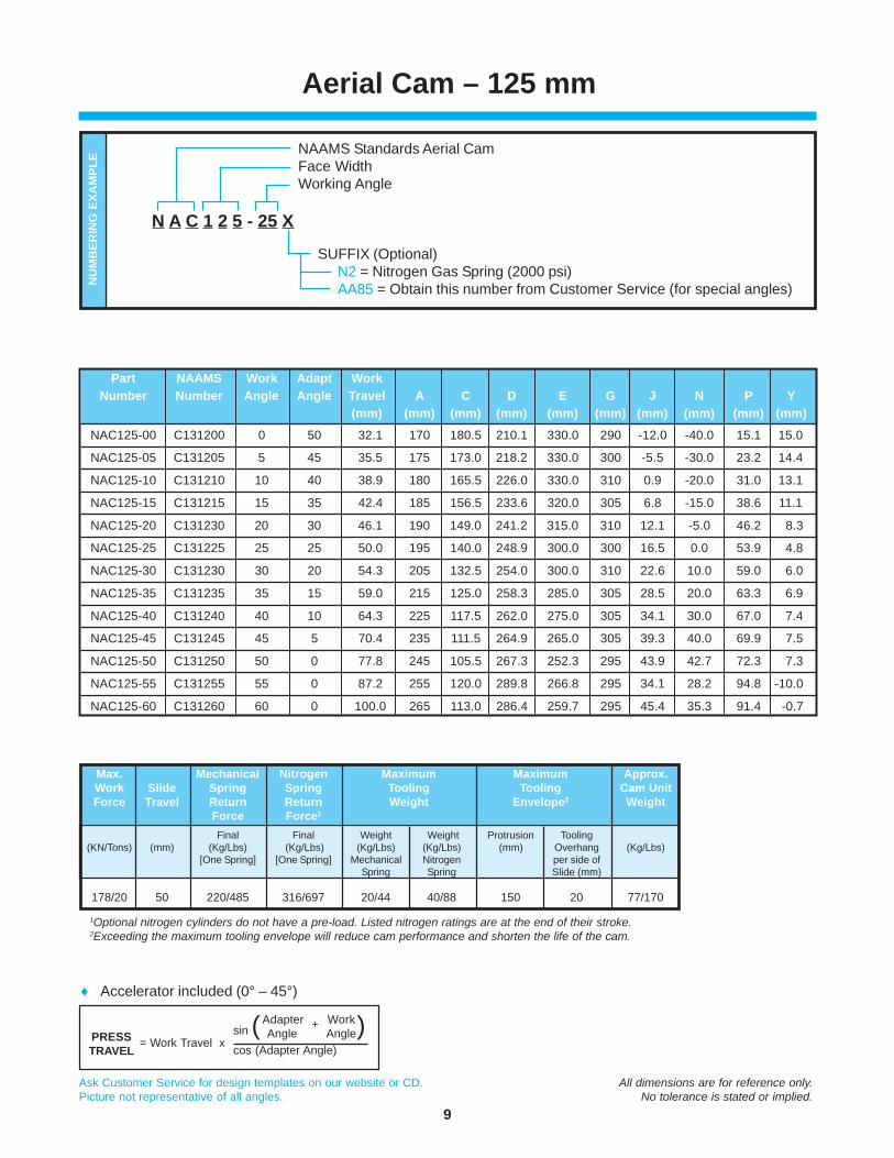
Part NAAMS Work Adapt WorkNumber Number Angle Angle Travel A C D E G J N P Y
(mm) (mm) (mm) (mm) (mm) (mm) (mm) (mm) (mm) (mm)
NAC125-00 C131200 0 50 32.1 170 180.5 210.1 330.0 290 -12.0 -40.0 15.1 15.0
NAC125-05 C131205 5 45 35.5 175 173.0 218.2 330.0 300 -5.5 -30.0 23.2 14.4
NAC125-10 C131210 10 40 38.9 180 165.5 226.0 330.0 310 0.9 -20.0 31.0 13.1
NAC125-15 C131215 15 35 42.4 185 156.5 233.6 320.0 305 6.8 -15.0 38.6 11.1
NAC125-20 C131230 20 30 46.1 190 149.0 241.2 315.0 310 12.1 -5.0 46.2 8.3
NAC125-25 C131225 25 25 50.0 195 140.0 248.9 300.0 300 16.5 0.0 53.9 4.8
NAC125-30 C131230 30 20 54.3 205 132.5 254.0 300.0 310 22.6 10.0 59.0 6.0
NAC125-35 C131235 35 15 59.0 215 125.0 258.3 285.0 305 28.5 20.0 63.3 6.9
NAC125-40 C131240 40 10 64.3 225 117.5 262.0 275.0 305 34.1 30.0 67.0 7.4
NAC125-45 C131245 45 5 70.4 235 111.5 264.9 265.0 305 39.3 40.0 69.9 7.5
NAC125-50 C131250 50 0 77.8 245 105.5 267.3 252.3 295 43.9 42.7 72.3 7.3
NAC125-55 C131255 55 0 87.2 255 120.0 289.8 266.8 295 34.1 28.2 94.8 -10.0
NAC125-60 C131260 60 0 100.0 265 113.0 286.4 259.7 295 45.4 35.3 91.4 -0.7
Aerial Cam – 125 mm
NAAMS Standards Aerial CamFace WidthWorking Angle
SUFFIX (Optional)N2 = Nitrogen Gas Spring (2000 psi)AA85 = Obtain this number from Customer Service (for special angles)
N A C 1 2 5 - 25 X
NU
MB
ERIN
G E
XAM
PLE
♦ Accelerator included (0° – 45°)
1Optional nitrogen cylinders do not have a pre-load. Listed nitrogen ratings are at the end of their stroke.2Exceeding the maximum tooling envelope will reduce cam performance and shorten the life of the cam.
Max. Mechanical Nitrogen Maximum Maximum Approx.Work Slide Spring Spring Tooling Tooling Cam UnitForce Travel Return Return Weight Envelope2 Weight
Force Force1
Final Final Weight Weight Protrusion Tooling(KN/Tons) (mm) (Kg/Lbs) (Kg/Lbs) (Kg/Lbs) (Kg/Lbs) (mm) Overhang (Kg/Lbs)
[One Spring] [One Spring] Mechanical Nitrogen per side ofSpring Spring Slide (mm)
178/20 50 220/485 316/697 20/44 40/88 150 20 77/170
PRESSTRAVEL = Work Travel x
sin ( )cos (Adapter Angle)
Adapter + WorkAngle Angle

10
Ask Customer Service for design templates on our website or CD. All dimensions are for reference only.Picture not representative of all angles. No tolerance is stated or implied.
Aerial Cam – 150 mm
0 16 179
2X ø16 DOWELS
BOTTOM VIEW (Driver Only)
4X M16 MOUNTINGSCREWS TOOLING
MOUNTING FACE
SIDE VIEW150
120
P
52
0
52
CUSTOMERSUPPLIEDBACK KEY
REF.
195D
116.7
WORKANGLE
300 SLIDETRAVEL
150.7MAX.
WORKTRAVEL
Y
AJ
GE
CN
0 18 48
2X ø16 DOWELS 4X M16
MOUNTINGSCREWS
Q
78
0
78
TOP VIEW
190
12
TOOLINGFACE CL
TOOLINGBALL CL
PRESS TRAVEL
SLIDETRAVEL
50 mm
WORKTRAVEL WORK
ANGLE
ADAPTERANGLE
CAM MOTION
Ø12
12
NAAMS TOOLING BALL
0° 2725° 282
10° 29215° 28720° 29225° 28230° 29235° 28740° 28745° 28750° 27755° 27760° 277
WORKANGLE Q
Tooling ball located at “A” dimension per NAAMS.“Y” dimension represents the tooling ball from the slide centerline.
Dowel holes undersized 0.2/0.3mm.
Tooling ball is not suppliedwith the cam and is
a reference point only.

11
Ask Customer Service for design templates on our website or CD. All dimensions are for reference only.Picture not representative of all angles. No tolerance is stated or implied.
Aerial Cam – 150 mm
NAAMS Standards Aerial CamFace WidthWorking Angle
SUFFIX (Optional)N2 = Nitrogen Gas Spring (2000 psi)AA85 = Obtain this number from Customer Service (for special angles)
N A C 1 5 0 - 25 X
NU
MB
ERIN
G E
XAM
PLE
♦ Accelerator included (0° – 45°)
1Optional nitrogen cylinders do not have a pre-load. Listed nitrogen ratings are at the end of their stroke.2Exceeding the maximum tooling envelope will reduce cam performance and shorten the life of the cam.
Max. Mechanical Nitrogen Maximum Maximum Approx.Work Slide Spring Spring Tooling Tooling Cam UnitForce Travel Return Return Weight Envelope2 Weight
Force Force1
Final Final Weight Weight Protrusion Tooling(KN/Tons) (mm) (Kg/Lbs) (Kg/Lbs) (Kg/Lbs) (Kg/Lbs) (mm) Overhang (Kg/Lbs)
[Two Springs] [Two Springs] Mechanical Nitrogen per side ofSpring Spring Slide (mm)
223/25 50 440/970 632/1394 20/44 40/88 150 20 96/210
Part NAAMS Work Adapt WorkNumber Number Angle Angle Travel A C D E G J N P Y
(mm) (mm) (mm) (mm) (mm) (mm) (mm) (mm) (mm) (mm)
NAC150-00 C131500 0 50 32.1 170 180.5 210.1 330.0 290 -12.0 -40.0 15.1 15.0
NAC150-05 C131505 5 45 35.5 175 173.0 218.2 330.0 300 -5.5 -30.0 23.2 14.4
NAC150-10 C131510 10 40 38.9 180 165.5 226.0 330.0 310 0.9 -20.0 31.0 13.1
NAC150-15 C131515 15 35 42.4 185 156.5 233.6 320.0 305 6.8 -15.0 38.6 11.1
NAC150-20 C131520 20 30 46.1 190 149.0 241.2 315.0 310 12.1 -5.0 46.2 8.3
NAC150-25 C131525 25 25 50.0 195 140.0 248.9 300.0 300 16.5 0.0 53.9 4.8
NAC150-30 C131530 30 20 54.3 205 132.5 254.0 300.0 310 22.6 10.0 59.0 5.7
NAC150-35 C131535 35 15 59.0 215 125.0 258.3 285.0 305 28.5 20.0 63.3 6.9
NAC150-40 C131540 40 10 64.3 225 117.5 262.0 275.0 305 34.1 30.0 67.0 7.4
NAC150-45 C131545 45 5 70.4 235 111.5 264.9 265.0 305 39.3 40.0 69.9 7.5
NAC150-50 C131550 50 0 77.8 245 105.5 267.3 252.3 295 43.9 42.7 72.3 7.3
NAC150-55 C131555 55 0 87.2 255 120.0 289.8 266.8 295 34.1 28.2 94.8 -10.0
NAC150-60 C131560 60 0 100.0 265 113.0 289.3 259.7 295 45.4 35.3 94.3 -0.7
PRESSTRAVEL = Work Travel x
sin ( )cos (Adapter Angle)
Adapter + WorkAngle Angle

12
Ask Customer Service for design templates on our website or CD. All dimensions are for reference only.Picture not representative of all angles. No tolerance is stated or implied.
Aerial Cam – 175 mm
TOP VIEW
2X ø16 DOWELS
4X M16 MOUNTINGSCREWS64.5
0
64.5
0 16 179
BOTTOM VIEW (Driver Only)
SIDE VIEW
12
215
90
0
90
0 18 48
2X ø16 DOWELS
4X M16 MOUNTINGSCREWSQ
GE
CN
AJ
WORKTRAVEL
150.7MAX.
116.7
SLIDETRAVEL
WORKANGLE
300
195D
Y
P
175
120
TOOLINGFACE CL
TOOLINGBALL CL
TOOLINGMOUNTING FACE
PRESS TRAVEL
SLIDETRAVEL
50 mm
WORKTRAVEL WORK
ANGLE
ADAPTERANGLE
CAM MOTION
Ø12
12
NAAMS TOOLING BALL
0° 2725° 28210° 29215° 28720° 29225° 28230° 29235° 28740° 28745° 28750° 27755° 27760° 277
WORKANGLE Q
Tooling ball located at “A” dimension per NAAMS.“Y” dimension represents the tooling ball from the slide centerline.
Dowel holes undersized 0.2/0.3mm.
Tooling ball is not suppliedwith the cam and is
a reference point only.

13
Ask Customer Service for design templates on our website or CD. All dimensions are for reference only.Picture not representative of all angles. No tolerance is stated or implied.
Aerial Cam – 175 mm
NAAMS Standards Aerial CamFace WidthWorking Angle
SUFFIX (Optional)N2 = Nitrogen Gas Spring (2000 psi)AA85 = Obtain this number from Customer Service (for special angles)
N A C 1 7 5 - 25 X
NU
MB
ERIN
G E
XAM
PLE
♦ Accelerator included (0° – 45°)
1Optional nitrogen cylinders do not have a pre-load. Listed nitrogen ratings are at the end of their stroke.2Exceeding the maximum tooling envelope will reduce cam performance and shorten the life of the cam.
Max. Mechanical Nitrogen Maximum Maximum Approx.Work Slide Spring Spring Tooling Tooling Cam UnitForce Travel Return Return Weight Envelope2 Weight
Force Force1
Final Final Weight Weight Protrusion Tooling(KN/Tons) (mm) (Kg/Lbs) (Kg/Lbs) (Kg/Lbs) (Kg/Lbs) (mm) Overhang (Kg/Lbs)
[Two Springs] [Two Springs] Mechanical Nitrogen per side ofSpring Spring Slide (mm)
267/30 50 440/970 632/1394 32/71 64/141 175 30 105/230
Part NAAMS Work Adapt WorkNumber Number Angle Angle Travel A C D E G J N P Y
(mm) (mm) (mm) (mm) (mm) (mm) (mm) (mm) (mm) (mm)
NAC175-00 C131700 0 50 32.1 170 180.5 210.1 330 290 -12.0 -40.0 15.1 15.0
NAC175-05 C131705 5 45 35.5 175 173.0 218.2 330 300 -5.5 -30.0 23.2 14.4
NAC175-10 C131710 10 40 38.9 180 165.5 226.0 330 310 0.9 -20.0 31.0 13.1
NAC175-15 C131715 15 35 42.4 185 156.5 233.6 320 305 6.8 -15.0 38.6 11.1
NAC175-20 C131720 20 30 46.1 190 149.0 241.2 315 310 12.1 -5.0 46.2 8.3
NAC175-25 C131725 25 25 50.0 195 140.0 248.9 300 300 16.5 0.0 53.9 4.8
NAC175-30 C131730 30 20 54.3 205 132.5 254.0 300 310 22.6 10.0 59.0 6.0
NAC175-35 C131735 35 15 59.0 215 125.0 258.3 285 305 28.6 20.0 63.3 6.9
NAC175-40 C131740 40 10 64.3 225 117.5 262.0 275 305 34.1 30.0 67.0 7.4
NAC175-45 C131745 45 5 70.4 235 111.5 264.9 265 305 39.3 40.0 69.9 7.5
NAC175-50 C131750 50 0 77.8 245 105.5 267.3 252.3 295 43.9 42.7 72.3 7.3
NAC175-55 C131755 55 0 87.2 255 120.0 289.9 266.8 295 34.1 28.2 94.9 -10.0
NAC175-60 C131760 60 0 100.0 265 113.0 289.3 259.7 295 45.4 35.3 94.3 -0.7
PRESSTRAVEL = Work Travel x
sin ( )cos (Adapter Angle)
Adapter + WorkAngle Angle

14
Ask Customer Service for design templates on our website or CD. All dimensions are for reference only.Picture not representative of all angles. No tolerance is stated or implied.
Aerial Cam – 200 mm
TOP VIEW
GE
C N
AJ
Y
WORKTRAVEL
150.7MAX.
WORKANGLE
SLIDETRAVEL
116.7
195D
P
300
77
0
77
0 16 179
2X ø16 DOWELS
4X M16 MOUNTINGSCREWS
BOTTOM VIEW (Driver Only)
200
120
12
240
SIDE VIEW
TOOLINGFACE CL TOOLING
BALL CL
103
0
103
0 18 48
2X ø16 DOWELS
4X M16 MOUNTINGSCREWSQ
TOOLING MOUNTING FACE
PRESS TRAVEL
SLIDETRAVEL
50 mm
WORKTRAVEL WORK
ANGLE
ADAPTERANGLE
CAM MOTION
Ø12
12
NAAMS TOOLING BALL
0° 2725° 282
10° 29215° 28720° 29225° 28230° 29235° 28740° 28745° 28750° 27755° 27760° 277
WORKANGLE Q
Tooling ball located at “A” dimension per NAAMS.“Y” dimension represents the tooling ball from the slide centerline.
Dowel holes undersized 0.2/0.3mm.
Tooling ball is not suppliedwith the cam and is
a reference point only.

15
Ask Customer Service for design templates on our website or CD. All dimensions are for reference only.Picture not representative of all angles. No tolerance is stated or implied.
Part NAAMS Work Adapt WorkNumber Number Angle Angle Travel A C D E G J N P Y
(mm) (mm) (mm) (mm) (mm) (mm) (mm) (mm) (mm) (mm)
NAC200-00 C132000 0 50 32.1 170 180.5 210.1 330 290 -12.0 -40.0 15.1 15.0
NAC200-05 C132005 5 45 35.5 175 173.0 218.2 330 300 -5.5 -30.0 23.2 14.4
NAC200-10 C132010 10 40 38.9 180 165.5 226.0 330 310 0.9 -20.0 31.0 13.1
NAC200-15 C132015 15 35 42.4 185 156.5 233.6 320 305 6.8 -15.0 38.6 11.1
NAC200-20 C132020 20 30 46.1 190 149.0 241.2 315 310 12.1 -5.0 46.2 8.3
NAC200-25 C132025 25 25 50.0 195 140.0 248.9 300 300 16.5 0.0 53.9 4.8
NAC200-30 C132030 30 20 54.3 205 132.5 254.0 300 310 22.6 10.0 59.0 6.0
NAC200-35 C132035 35 15 59.0 215 125.0 258.3 285 305 28.6 20.0 63.3 6.9
NAC200-40 C132040 40 10 64.3 225 117.5 262.0 275 305 34.1 30.0 67.0 7.4
NAC200-45 C132045 45 5 70.4 235 111.5 264.9 265 305 39.3 40.0 69.9 7.5
NAC200-50 C132050 50 0 77.8 245 105.5 267.3 252.3 295 43.9 42.7 72.3 7.3
NAC200-55 C132055 55 0 87.2 255 120.0 289.9 266.8 295 34.1 28.2 94.9 -10.0
NAC200-60 C132060 60 0 100.0 265 113.0 289.3 259.7 295 45.4 35.3 94.3 -0.7
Aerial Cam – 200 mm
NAAMS Standards Aerial CamFace WidthWorking Angle
SUFFIX (Optional)N2 = Nitrogen Gas Spring (2000 psi)AA85 = Obtain this number from Customer Service (for special angles)
N A C 2 0 0 - 25 X
NU
MB
ERIN
G E
XAM
PLE
♦ Accelerator included (0° – 45°)
Max. Mechanical Nitrogen # Optional Return Maximum Maximum Approx.Work Slide Spring Spring Nitrogen Force per Tooling Tooling Cam UnitForce Travel Return Return Cylinder Nitrogen Weight Envelope3 Weight
Force Force1 Pockets2 SpringFinal Final Final Weight Weight Protrusion Tooling
(KN/Tons) (mm) (Kg/Lbs) (Kg/Lbs) (Kg/Lbs) (Kg/Lbs) (Kg/Lbs) (mm) Overhang (Kg/Lbs)[Three Springs] [Two Springs] Mechanical Nitrogen per side of
Spring Spring Slide (mm)
312/35 50 660/1455 632/1394 1 316/697 32/71 64/141 175 30 127/280
1Nitrogen cylinders do not have a pre-load. Listed nitrogen ratings are at the end of their stroke.2Three spring pockets built into the cam, two nitrogen springs supplied with nitrogen spring configuration. Spring return calculated based on the standard spring quantity. Customer can add an additional spring for more return force.3Exceeding the maximum tooling envelope will reduce cam performance and shorten the life of the cam.
PRESSTRAVEL = Work Travel x
sin ( )cos (Adapter Angle)
Adapter + WorkAngle Angle

16
Ask Customer Service for design templates on our website or CD. All dimensions are for reference only.Picture not representative of all angles. No tolerance is stated or implied.
Aerial Cam – 250 mm
TOOLING MOUNTING FACE
375
0 25 T U
BOTTOM VIEW (Driver Only)
4X M20 MOUNTINGSCREWS
2X Ø20 DOWELS
133
0
133
CUSTOMER SUPPLIEDBACK KEY
REF.
SLIDETRAVEL
WORKANGLE
HD
P
M 149MAX.
Y
WORKTRAVEL
J A
GE N
250
160
SIDE VIEW
12
310
TOP VIEW
TOOLINGFACE CL TOOLING
BALL CL
C
133
0
133
0 25 55
2X ø20 DOWELS4X M20 MOUNTING SCREWS
Q
PRESS TRAVEL
SLIDETRAVEL
60 mm
WORKTRAVEL WORK
ANGLE
ADAPTERANGLE
CAM MOTION
Ø12
12
NAAMS TOOLING BALL
0° 320 170 2105° 335 170 210
10° 345 170 21015° 355 170 21020° 370 170 21025° 375 160 20030° 375 145 18535° 375 145 18540° 375 135 17545° 375 130 17050° 350 135 17555° 350 135 17560° 350 135 175
WORKANGLE Q T U
Tooling ball located at “A” dimension per NAAMS.“Y” dimension represents the tooling ball from the slide centerline.
Dowel holes undersized 0.2/0.3mm.
Tooling ball is not suppliedwith the cam and is
a reference point only.

17
Ask Customer Service for design templates on our website or CD. All dimensions are for reference only.Picture not representative of all angles. No tolerance is stated or implied.
Part NAAMS Work Adapt WorkNumber Number Angle AngleTravel A C D E G H J M N P Y
(mm) (mm) (mm) (mm) (mm) (mm) (mm) (mm) (mm) (mm) (mm) (mm)
NAC250-00 C132500 0 50 38.6 180.0 193.0 242.0 345.0 345 235 -12.0 103.0 0.0 7.0 14.1
NAC250-05 C132505 5 45 42.6 185.0 182.5 255.7 350.0 360 235 -4.1 103.0 10.0 20.7 10.7
NAC250-10 C132510 10 40 46.7 190.0 172.0 269.8 350.0 370 235 3.1 103.0 20.0 34.8 6.0
NAC250-15 C132515 15 35 50.9 195.0 161.5 283.3 350.0 380 235 10.5 103.0 30.0 48.3 5.2
NAC250-20 C132520 20 30 55.3 200.0 151.0 296.8 345.0 395 235 17.2 103.0 50.0 61.8 3.1
NAC250-25 C132525 25 25 60.0 205.0 140.5 300.6 345.0 400 225 22.8 103.0 55.0 75.6 -0.3
NAC250-30 C132530 30 20 65.1 215.0 130.0 297.0 335.0 400 210 29.9 103.0 65.0 87.0 0.5
NAC250-35 C132535 35 15 70.8 225.0 121.0 308.1 320.0 400 210 36.2 103.0 80.0 98.1 0.2
NAC250-40 C132540 40 10 77.1 235.0 112.0 309.1 315.0 400 200 41.3 103.0 85.0 109.1 -1.4
NAC250-45 C132545 45 5 84.5 245.0 103.0 315.3 310.0 400 195 45.0 103.0 90.0 120.3 -4.4
NAC250-50 C132550 50 0 93.3 265.0 94.0 320.1 289.8 375 200 58.5 103.0 85.2 120.1 6.5
NAC250-55 C132555 55 0 104.6 285.0 86.5 325.2 277.5 375 200 68.2 108.0 97.5 125.2 11.6
NAC250-60 C132560 60 0 120.0 300.0 79.0 326.9 263.0 375 200 76.3 108.0 112.0 126.9 15.0
Aerial Cam – 250 mm
NAAMS Standards Aerial CamFace WidthWorking Angle
SUFFIX (Optional)N2 = Nitrogen Gas Spring (2000 psi)AA85 = Obtain this number from Customer Service (for special angles)
N A C 2 5 0 - 25 X
NU
MB
ERIN
G E
XAM
PLE
♦ Accelerator included (0° – 45°)
Max. Mechanical Nitrogen # Optional Return Maximum Maximum Approx.Work Slide Spring Spring Nitrogen Force per Tooling Tooling Cam UnitForce Travel Return Return Cylinder Nitrogen Weight Envelope3 Weight
Force Force 1 Pockets2 SpringFinal Final Final Weight Weight Protrusion Tooling
(KN/Tons) (mm) (Kg/Lbs) (Kg/Lbs) (Kg/Lbs) (Kg/Lbs) (Kg/Lbs) (mm) Overhang (Kg/Lbs)[Three Springs] [Two Springs] Mechanical Nitrogen per side of
Spring Spring Slide (mm)
356/40 60 685/1512 640/1410 1 320/705 65/143 130/287 200 40 200/440
1Nitrogen cylinders do not have a pre-load. Listed nitrogen ratings are at the end of their stroke.2Three spring pockets built into the cam, two nitrogen springs supplied with nitrogen spring configuration. Spring return calculated based on the standard spring quantity. Customer can add an additional spring for more return force.3Exceeding the maximum tooling envelope will reduce cam performance and shorten the life of the cam.
PRESSTRAVEL = Work Travel x
sin ( )cos (Adapter Angle)
Adapter + WorkAngle Angle

18
Ask Customer Service for design templates on our website or CD. All dimensions are for reference only.Picture not representative of all angles. No tolerance is stated or implied.
TOP VIEW Q
4X M20 MOUNTING SCREWS
TOOLING MOUNTING FACE133
0
133
2X ø20 DOWELS
0 25
BOTTOM VIEW (Driver Only)
T U
SIDE VIEW
12
360
300160
TOOLINGFACECL
TOOLINGBALL CL
158
0
158
0 25 55
2X ø20 DOWELS4X M20 MOUNTING SCREWS
GE
SLIDETRAVEL
375
WORKANGLE
CUSTOMERSUPPLIEDBACK KEY
REF.
M
HD
P
Y
WORKTRAVEL
J A
CN
PRESS TRAVEL
SLIDETRAVEL
60 mm
WORKTRAVEL WORK
ANGLE
ADAPTERANGLE
CAM MOTION
Ø12
12
NAAMS TOOLING BALL
149MAX.
Aerial Cam – 300 mm
0° 320 170 2105° 335 170 21010° 345 170 21015° 355 170 21020° 370 170 21025° 375 160 20030° 375 145 18535° 375 145 18540° 375 135 17545° 375 130 17050° 350 135 17555° 350 135 17560° 350 135 175
WORKANGLE Q T U
Tooling ball located at “A” dimension per NAAMS.“Y” dimension represents the tooling ball from the slide centerline.
Dowel holes undersized 0.2/0.3mm.
Tooling ball is not suppliedwith the cam and is
a reference point only.

19
Ask Customer Service for design templates on our website or CD. All dimensions are for reference only.Picture not representative of all angles. No tolerance is stated or implied.
Part NAAMS Work Adapt WorkNumber Number Angle Angle Travel A C D E G H J M N P Y
(mm) (mm) (mm) (mm) (mm) (mm) (mm) (mm) (mm) (mm) (mm) (mm)
NAC300-00 C133000 0 50 38.6 180.0 193.0 242.0 345 345 235 -12.0 103.0 0.0 7.0 14.1
NAC300-05 C133005 5 45 42.6 185.0 182.5 255.7 350 360 235 -4.1 103.0 10.0 20.7 10.7
NAC300-10 C133010 10 40 46.7 190.0 172.0 269.8 350 370 235 3.1 103.0 20.0 34.8 6.0
NAC300-15 C133015 15 35 50.9 195.0 161.5 283.3 350 380 235 10.5 103.0 30.0 48.3 5.2
NAC300-20 C133020 20 30 55.3 200.0 151.0 296.8 345 395 235 17.2 103.0 50.0 61.8 3.1
NAC300-25 C133025 25 25 60.0 205.0 140.5 300.6 345 400 225 22.8 103.0 55.0 75.6 -0.3
NAC300-30 C133030 30 20 65.1 215.0 130.0 297.0 335 400 210 29.9 103.0 65.0 87.0 0.5
NAC300-35 C133035 35 15 70.8 225.0 121.0 308.1 320 400 210 36.2 103.0 80.0 98.1 0.2
NAC300-40 C133040 40 10 77.1 235.0 112.0 309.1 315 400 200 41.3 103.0 85.0 109.1 -1.4
NAC300-45 C133045 45 5 84.5 245.0 103.0 315.3 310 400 195 45.0 103.0 90.0 120.3 -4.4
NAC300-50 C133050 50 0 93.3 265.0 94.0 320.1 289.8 375 200 58.5 103.0 85.2 120.1 6.5
NAC300-55 C133055 55 0 104.6 285.0 86.5 325.2 277.5 375 200 68.2 108.0 97.5 125.2 11.6
NAC300-60 C133060 60 0 120.0 300.0 79.0 326.9 263 375 200 76.3 108.0 112.0 126.9 15.0
Aerial Cam – 300 mm
NAAMS Standards Aerial CamFace WidthWorking Angle
SUFFIX (Optional)N2 = Nitrogen Gas Spring (2000 psi)AA85 = Obtain this number from Customer Service (for special angles)
N A C 3 0 0 - 25 X
NU
MB
ERIN
G E
XAM
PLE
♦ Accelerator included (0° – 45°)
Max. Mechanical Nitrogen # Optional Return Maximum Maximum Approx.Work Slide Spring Spring Nitrogen Force per Tooling Tooling Cam UnitForce Travel Return Return Cylinder Nitrogen Weight Envelope3 Weight
Force Force1 Pockets2 Spring SetFinal Final Final Weight Weight Protrusion Tooling
(KN/Tons) (mm) (Kg/Lbs) (Kg/Lbs) (Kg/Lbs) (Kg/Lbs) (Kg/Lbs) (mm) Overhang (Kg/Lbs)[Four Springs) [Two Springs] Mechanical Nitrogen per side of
Spring Spring Slide (mm)
444/50 60 912.4/2016 640/1410 2 320/705 65/143 130/287 200 50 227/500
1Nitrogen cylinders do not have a pre-load. Listed nitrogen ratings are at the end of their stroke.2Four spring pockets built into the cam, two nitrogen springs supplied with nitrogen spring configuration. Spring return calculated based on the standard spring quantity. Customer can add an additional one or two springs for more return force.3Exceeding the maximum tooling envelope will reduce cam performance and shorten the life of the cam.
PRESSTRAVEL = Work Travel x
sin ( )cos (Adapter Angle)
Adapter + WorkAngle Angle

20
Ask Customer Service for design templates on our website or CD. All dimensions are for reference only.Picture not representative of all angles. No tolerance is stated or implied.
Die Mount Cam – 50 mm
CUSTOMER SUPPLIED
BACK KEY REF.
TOOLING MOUNTING
FACE
D
H
J
225
WORKANGLE
WORKTRAVEL
C
E
G
N
A75
50
SIDE VIEW
90
0 15
BOTTOM VIEW (Body only)
2X M12 MOUNTING SCREWS
2X Ø12 DOWELS
12.50
12.5
315
TOP VIEW (Driver only)
0 15 Q
12.50
12.5
4X M12 MOUNTING SCREWS
2X Ø12 DOWELS
Y
TOOLINGFACE CL
CLTOOLINGBALL
12
Ø12
12
NAAMS TOOLING BALL
MOUNTINGFACE
0° 1505° 160
10° 16515° 17020° 170
WORKANGLE Q
Tooling ball located at “A” dimension per NAAMS.“Y” dimension represents the tooling ball from the slide centerline.
Dowel holes undersized 0.2/0.3mm.
Tooling ball is not suppliedwith the cam and is
a reference point only.

21
Ask Customer Service for design templates on our website or CD. All dimensions are for reference only.Picture not representative of all angles. No tolerance is stated or implied.
Part NAAMS Work WorkNumber Number Angle Travel A C D E G H J N Y
(mm) (mm) (mm) (mm) (mm) (mm) (mm) (mm) (mm) (mm)
NDM050-00 C230500 0 45 160 170.0 242.0 292.0 330 165 -12 38.0 0.0
NDM050-05 C230505 5 45 150 180.0 247.5 300.0 330 175 -8.7 30.0 0.0
NDM050-10 C230510 10 45 140 190.0 248.0 308.0 330 180 -5.3 22.0 0.0
NDM050-15 C230515 15 45 135 200.0 250.8 325.3 330 185 -1.9 4.7 0.0
NDM050-20 C230520 20 45 130 210.0 247.8 325.3 330 185 -1.6 4.7 0.0
Die Mount Cam – 50 mm
NAAMS Standards Die Mount CamFace WidthWorking Angle
SUFFIX (Optional)N2 = Nitrogen Gas Spring (2000 psi)AA85 = Obtain this number from Customer Service (for special angles)
N D M 0 5 0 - 20 X
NU
MB
ERIN
G E
XAM
PLE
1Optional nitrogen cylinders do not have a pre-load. Listed nitrogen ratings are at the end of their stroke.2Exceeding the maximum tooling envelope will reduce cam performance and shorten the life of the cam.
Max. Mechanical Nitrogen Maximum Maximum Approx.Work Slide Spring Spring Tooling Tooling Cam UnitForce Travel Return Return Weight Envelope2 Weight
Force Force1
Final Final Weight Weight Protrusion Tooling(KN/Tons) (mm) (Kg/Lbs) (Kg/Lbs) (Kg/Lbs) (Kg/Lbs) (mm) Overhang (Kg/Lbs)
[One Spring] [One Spring] Mechanical Nitrogen per side ofSpring Spring Slide (mm)
134/15 45 58/128 94/208 8/18 16/35 125 25 28/60

22
Ask Customer Service for design templates on our website or CD. All dimensions are for reference only.Picture not representative of all angles. No tolerance is stated or implied.
Die Mount Cam – 75 mm
C
E
G
TOP VIEW (Driver Only)
20
020
0 18 Q
2X ø12 DOWELS
4X M12 MOUNTING SCREWS
CUSTOMER SUPPLIED
BACK KEY REF.
D
H
WORKTRAVEL275
J
Y
A
75
364
2X ø12 DOWELS
0 16
180
18
BOTTOM VIEW (Body Only)
4X M12 MOUNTING SCREWS
TOOLING MOUNTING
FACEN
90
12
SIDE VIEW
TOOLINGFACE CL TOOLING
BALLCL
115
Ø12
12
NAAMS TOOLING BALL
MOUNTINGFACE
0° 1675° 172
10° 18215° 18220° 182
WORKANGLE Q
Tooling ball located at “A” dimension per NAAMS.“Y” dimension represents the tooling ball from the slide centerline.
Dowel holes undersized 0.2/0.3mm.
Tooling ball is not suppliedwith the cam and is
a reference point only.
23
Ask Customer Service for design templates on our website or CD. All dimensions are for reference only.Picture not representative of all angles. No tolerance is stated or implied.
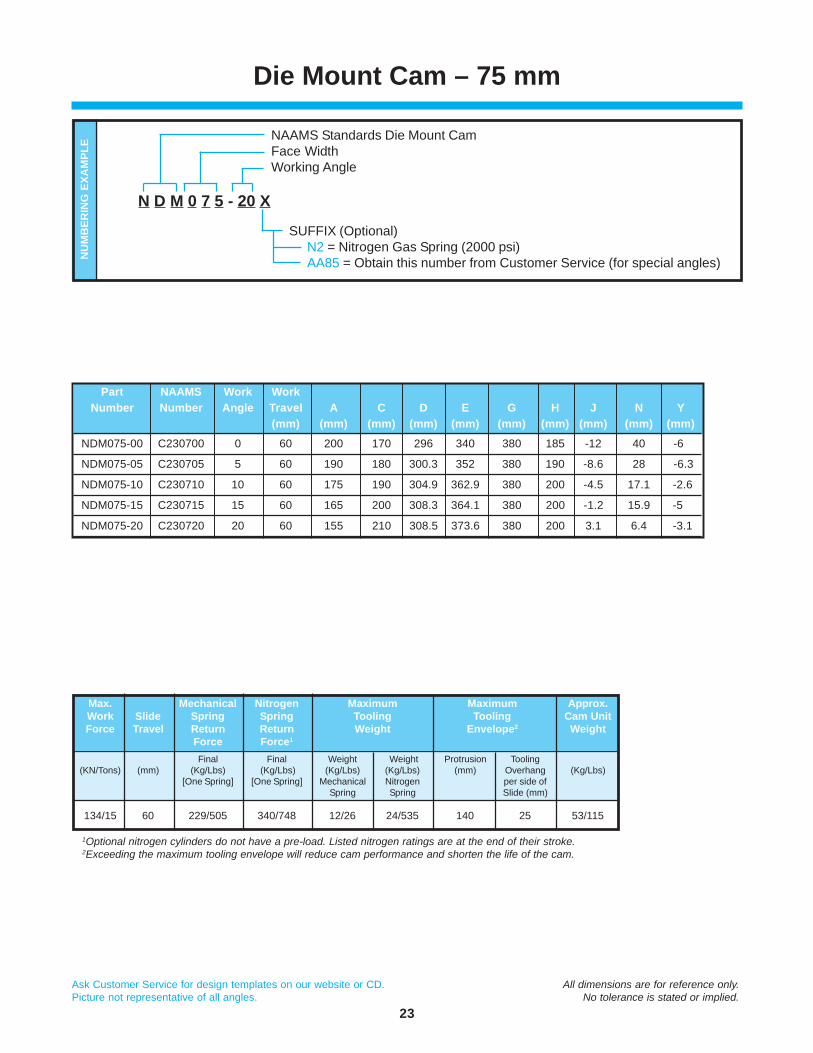
Part NAAMS Work WorkNumber Number Angle Travel A C D E G H J N Y
(mm) (mm) (mm) (mm) (mm) (mm) (mm) (mm) (mm) (mm)
NDM075-00 C230700 0 60 200 170 296 340 380 185 -12 40 -6
NDM075-05 C230705 5 60 190 180 300.3 352 380 190 -8.6 28 -6.3
NDM075-10 C230710 10 60 175 190 304.9 362.9 380 200 -4.5 17.1 -2.6
NDM075-15 C230715 15 60 165 200 308.3 364.1 380 200 -1.2 15.9 -5
NDM075-20 C230720 20 60 155 210 308.5 373.6 380 200 3.1 6.4 -3.1
Die Mount Cam – 75 mm
NAAMS Standards Die Mount CamFace WidthWorking Angle
SUFFIX (Optional)N2 = Nitrogen Gas Spring (2000 psi)AA85 = Obtain this number from Customer Service (for special angles)
N D M 0 7 5 - 20 X
NU
MB
ERIN
G E
XAM
PLE
1Optional nitrogen cylinders do not have a pre-load. Listed nitrogen ratings are at the end of their stroke.2Exceeding the maximum tooling envelope will reduce cam performance and shorten the life of the cam.
Max. Mechanical Nitrogen Maximum Maximum Approx.Work Slide Spring Spring Tooling Tooling Cam UnitForce Travel Return Return Weight Envelope2 Weight
Force Force1
Final Final Weight Weight Protrusion Tooling(KN/Tons) (mm) (Kg/Lbs) (Kg/Lbs) (Kg/Lbs) (Kg/Lbs) (mm) Overhang (Kg/Lbs)
[One Spring] [One Spring] Mechanical Nitrogen per side ofSpring Spring Slide (mm)
134/15 60 229/505 340/748 12/26 24/535 140 25 53/115

24
Ask Customer Service for design templates on our website or CD. All dimensions are for reference only.Picture not representative of all angles. No tolerance is stated or implied.
Die Mount Cam – 150 mm
CEG
CUSTOMER SUPPLIEDBACK KEY
REF.
TOP VIEW (Driver Only)
4X M16 MOUNTING SCREWS54
0
54
0 18 Q
2X ø16 DOWELS
WORKTRAVEL
300
H
D
J
WORKANGLE
0 16
2X ø16 DOWELS
54
0
54
BOTTOM VIEW (Body Only)
4X M16 MOUNTING SCREWS
374
12N
A Y
120
SIDE VIEWTOOLING
MOUNTING FACE
190
150
TOOLINGFACE CL
TOOLINGBALL CL
Ø12
12
NAAMS TOOLING BALL
MOUNTINGFACE
0° 1775° 177
10° 18215° 19220° 207
WORKANGLE Q
Tooling ball located at “A” dimension per NAAMS.“Y” dimension represents the tooling ball from the slide centerline.
Dowel holes undersized 0.2/0.3mm.
Tooling ball is not suppliedwith the cam and is
a reference point only.

25
Ask Customer Service for design templates on our website or CD. All dimensions are for reference only.Picture not representative of all angles. No tolerance is stated or implied.
Part NAAMS Work WorkNumber Number Angle Travel A C D E G H J N Y
(mm) (mm) (mm) (mm) (mm) (mm) (mm) (mm) (mm) (mm)
NDM150-00 C231500 0 60 200 170.0 296.0 350.0 390 195 -12 40.0 -1.0
NDM150-05 C231505 5 60 190 180.0 301.2 362.9 390 195 -6.8 27.1 -1.4
NDM150-10 C231510 10 60 175 190.0 306.7 374.7 390 200 -1 15.3 2.2
NDM150-15 C231515 15 60 165 200.0 311.0 376.8 390 210 3.9 13.2 -0.3
NDM150-20 C231520 20 60 155 210.0 312.2 387.2 390 225 9.7 2.8 1.3
Die Mount Cam – 150 mm
NAAMS Standards Die Mount CamFace WidthWorking Angle
SUFFIX (Optional)N2 = Nitrogen Gas Spring (2000 psi)AA85 = Obtain this number from Customer Service (for special angles)
N D M 1 5 0 - 20 X
NU
MB
ERIN
G E
XAM
PLE
♦ Accelerator included (0° – 20°)
1Optional nitrogen cylinders do not have a pre-load. Listed nitrogen ratings are at the end of their stroke.2Exceeding the maximum tooling envelope will reduce cam performance and shorten the life of the cam.
Max. Mechanical Nitrogen Maximum Maximum Approx.Work Slide Spring Spring Tooling Tooling Cam UnitForce Travel Return Return Weight Envelope2 Weight
Force Force1
Final Final Weight Weight Protrusion Tooling(KN/Tons) (mm) (Kg/Lbs) (Kg/Lbs) (Kg/Lbs) (Kg/Lbs) (mm) Overhang (Kg/Lbs)
[Two Springs] [Two Springs] Mechanical Nitrogen per side ofSpring Spring Slide (mm)
223/25 60 458/1010 680/1496 20/44 40/88 150 45 100/220

26
Ask Customer Service for design templates on our website or CD. All dimensions are for reference only.Picture not representative of all angles. No tolerance is stated or implied.
Die Mount Cam – 200 mm
TOP VIEW (Driver Only)
75
0
75
0 18 Q
2X ø16 DOWELS
4X M16 MOUNTING SCREWS
DH
300
WORKTRAVEL
WORKANGLE
J
CUSTOMER SUPPLIEDBACK KEY
REF.
A Y
C
EG TOOLING
MOUNTING FACE
200
120
12
240
374
2X ø16 DOWELS
0 16
BOTTOM VIEW (Body Only)
4X M16MOUNTING SCREWS
SIDE VIEW
TOOLINGFACE CL TOOLING
BALL CL
75
0
75
Ø12
12
NAAMS TOOLING BALL
MOUNTINGFACE
N
0° 1775° 17710° 18215° 19220° 207
WORKANGLE Q
Tooling ball located at “A” dimension per NAAMS.“Y” dimension represents the tooling ball from the slide centerline.
Dowel holes undersized 0.2/0.3mm.
Tooling ball is not suppliedwith the cam and is
a reference point only.
27
Ask Customer Service for design templates on our website or CD. All dimensions are for reference only.Picture not representative of all angles. No tolerance is stated or implied.
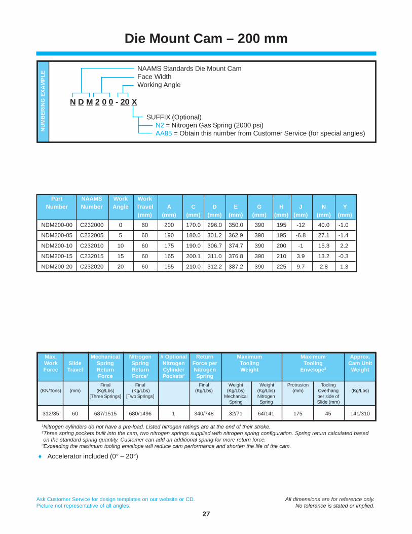
Part NAAMS Work WorkNumber Number Angle Travel A C D E G H J N Y
(mm) (mm) (mm) (mm) (mm) (mm) (mm) (mm) (mm) (mm)
NDM200-00 C232000 0 60 200 170.0 296.0 350.0 390 195 -12 40.0 -1.0
NDM200-05 C232005 5 60 190 180.0 301.2 362.9 390 195 -6.8 27.1 -1.4
NDM200-10 C232010 10 60 175 190.0 306.7 374.7 390 200 -1 15.3 2.2
NDM200-15 C232015 15 60 165 200.1 311.0 376.8 390 210 3.9 13.2 -0.3
NDM200-20 C232020 20 60 155 210.0 312.2 387.2 390 225 9.7 2.8 1.3
Die Mount Cam – 200 mm
NAAMS Standards Die Mount CamFace WidthWorking Angle
SUFFIX (Optional)N2 = Nitrogen Gas Spring (2000 psi)AA85 = Obtain this number from Customer Service (for special angles)
N D M 2 0 0 - 20 X
NU
MB
ERIN
G E
XAM
PLE
♦ Accelerator included (0° – 20°)
Max. Mechanical Nitrogen # Optional Return Maximum Maximum Approx.Work Slide Spring Spring Nitrogen Force per Tooling Tooling Cam UnitForce Travel Return Return Cylinder Nitrogen Weight Envelope3 Weight
Force Force1 Pockets2 SpringFinal Final Final Weight Weight Protrusion Tooling
(KN/Tons) (mm) (Kg/Lbs) (Kg/Lbs) (Kg/Lbs) (Kg/Lbs) (Kg/Lbs) (mm) Overhang (Kg/Lbs)[Three Springs] [Two Springs] Mechanical Nitrogen per side of
Spring Spring Slide (mm)
312/35 60 687/1515 680/1496 1 340/748 32/71 64/141 175 45 141/310
1Nitrogen cylinders do not have a pre-load. Listed nitrogen ratings are at the end of their stroke.2Three spring pockets built into the cam, two nitrogen springs supplied with nitrogen spring configuration. Spring return calculated based on the standard spring quantity. Customer can add an additional spring for more return force.3Exceeding the maximum tooling envelope will reduce cam performance and shorten the life of the cam.
28
Ask Customer Service for design templates on our website or CD. All dimensions are for reference only.Picture not representative of all angles. No tolerance is stated or implied.
Die Mount Cam – 250 mm
TOP VIEW (Driver Only)
133
0
133
0 25 175
215
2X ø20 DOWELS
4X M20 MOUNTINGSCREWS
U2Xø20 DOWELS
0 25 55
133
0
133
BOTTOM VIEW (Body Only)
4X M20 MOUNTING SCREWS
SIDE VIEW
DH
J
375
WORKTRAVEL
A
CUSTOMER SUPPLIEDBACK KEY
REF.
WORKANGLE
Y
12C
GE
250
TOOLING MOUNTING FACE
170
310
TOOLINGFACE CL TOOLING
BALL CL
Ø12
12
NAAMS TOOLING BALL
MOUNTINGFACE
N
0° 3505° 375
10° 37515° 37520° 375
WORKANGLE U
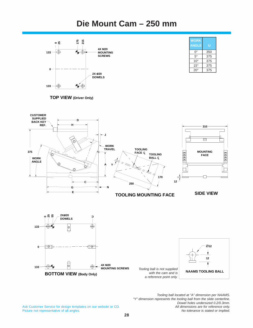
Tooling ball located at “A” dimension per NAAMS.“Y” dimension represents the tooling ball from the slide centerline.
Dowel holes undersized 0.2/0.3mm.
Tooling ball is not suppliedwith the cam and is
a reference point only.

29
Ask Customer Service for design templates on our website or CD. All dimensions are for reference only.Picture not representative of all angles. No tolerance is stated or implied.
Part NAAMS Work WorkNumber Number Angle Travel A C D E G H J N Y
(mm) (mm) (mm) (mm) (mm) (mm) (mm) (mm) (mm) (mm)
NDM250-00 C232500 0 60 260 170.0 359.2 372.0 375 240 -12 3.0 -3.4
NDM250-05 C232505 5 60 235 180.0 351.6 383.3 400 240 -4.4 16.7 2.1
NDM250-10 C232510 10 60 225 190.0 344.6 390.6 400 240 1.8 9.4 -6.6
NDM250-15 C232515 15 60 210 200.0 336.5 396.0 400 240 7.9 4.0 -9.5
NDM250-20 C232520 20 60 195 210.0 327.6 410.3 400 240 13.9 -10.3 -11.5
Die Mount Cam – 250 mm
NAAMS Standards Die Mount CamFace WidthWorking Angle
SUFFIX (Optional)N2 = Nitrogen Gas Spring (2000 psi)AA85 = Obtain this number from Customer Service (for special angles)
N D M 2 5 0 - 20 X
NU
MB
ERIN
G E
XAM
PLE
♦ Accelerator included (0° – 20°)
Max. Mechanical Nitrogen # Optional Return Maximum Maximum Approx.Work Slide Spring Spring Nitrogen Force per Tooling Tooling Cam UnitForce Travel Return Return Cylinder Nitrogen Weight Envelope3 Weight
Force Force1 Pockets2 SpringFinal Final Final Weight Weight Protrusion Tooling
(KN/Tons) (mm) (Kg/Lbs) (Kg/Lbs) (Kg/Lbs) (Kg/Lbs) (Kg/Lbs) (mm) Overhang (Kg/Lbs)[Three Springs] [Two Springs] Mechanical Nitrogen per side of
Spring Spring Slide (mm)
356/40 60 687/1515 640/1410 1 320/705 65/143 130/287 200 40 227/500
1Nitrogen cylinders do not have a pre-load. Listed nitrogen ratings are at the end of their stroke.2Three spring pockets built into the cam, two nitrogen springs supplied with nitrogen spring configuration. Spring return calculated based on the standard spring quantity. Customer can add an additional spring for more return force.3Exceeding the maximum tooling envelope will reduce cam performance and shorten the life of the cam.

30
Ask Customer Service for design templates on our website or CD. All dimensions are for reference only.Picture not representative of all angles. No tolerance is stated or implied.
Die Mount Cam – 300 mm
CG
E
TOP VIEW (Driver Only)
133
0
133
0 25 175
215
2X ø20 DOWELS
4X M20 MOUNTINGSCREWS
DH
375
WORKTRAVEL
CUSTOMER SUPPLIEDBACK KEY REF.
WORKANGLE
J
YA
U
2X M20 DOWELS0 25 55
158
0
158
BOTTOM VIEW (Body Only)
4X M20 MOUNTING SCREWS
300
TOOLING MOUNTING FACE
170
12
SIDE VIEW
TOOLINGFACE CL TOOLING
BALLCL
Ø12
12
NAAMS TOOLING BALL
360
MOUNTINGFACE
N
0° 3505° 375
10° 37515° 37520° 375
WORKANGLE U
Tooling ball located at “A” dimension per NAAMS.“Y” dimension represents the tooling ball from the slide centerline.
Dowel holes undersized 0.2/0.3mm.
Tooling ball is not suppliedwith the cam and is
a reference point only.

31
Ask Customer Service for design templates on our website or CD. All dimensions are for reference only.Picture not representative of all angles. No tolerance is stated or implied.
Part NAAMS Work WorkNumber Number Angle Travel A C D E G H J N Y
(mm) (mm) (mm) (mm) (mm) (mm) (mm) (mm) (mm) (mm)
NDM300-00 C233000 0 60 260 170.0 359.2 372.0 375 240 -12 3.0 -3.4
NDM300-05 C233005 5 60 235 180.0 351.6 383.3 400 240 -4.4 16.7 2.1
NDM300-10 C233010 10 60 225 190.0 344.6 390.6 400 240 1.8 9.4 -6.6
NDM300-15 C233015 15 60 210 200.0 336.5 396.0 400 240 7.9 4.0 -9.5
NDM300-20 C233020 20 60 195 210.0 327.6 410.3 400 240 13.9 -10.3 -11.5
Die Mount Cam – 300 mm
NAAMS Standards Die Mount CamFace WidthWorking Angle
SUFFIX (Optional)N2 = Nitrogen Gas Spring (2000 psi)AA85 = Obtain this number from Customer Service (for special angles)
N D M 3 0 0 - 20 X
NU
MB
ERIN
G E
XAM
PLE
♦ Accelerator included (0° – 20°)
Max. Mechanical Nitrogen # Optional Return Maximum Maximum Approx.Work Slide Spring Spring Nitrogen Force per Tooling Tooling Cam UnitForce Travel Return Return Cylinder Nitrogen Weight Envelope3 Weight
Force Force1 Pockets2 SpringFinal Final Final Weight Weight Protrusion Tooling
(KN/Tons) (mm) (Kg/Lbs) (Kg/Lbs) (Kg/Lbs) (Kg/Lbs) (Kg/Lbs) (mm) Overhang (Kg/Lbs)[Four Springs] [Two Springs] Mechanical Nitrogen per side of
Spring Spring Slide (mm)
444/50 60 916/2020 640/1410 2 320/705 65/143 130/287 200 50 254/560
1Nitrogen cylinders do not have a pre-load. Listed nitrogen ratings are at the end of their stroke.2Four spring pockets built into the cam, two nitrogen springs supplied with nitrogen spring configuration. Spring return calculated based on the standard spring quantity. Customer can add an additional one or two springs for more return force.3Exceeding the maximum tooling envelope will reduce cam performance and shorten the life of the cam.

32
Ask Customer Service for design templates on our website or CD. All dimensions are for reference only.Picture not representative of all angles. No tolerance is stated or implied.
Notes

33
Ask Customer Service for design templates on our website or CD. All dimensions are for reference only.Picture not representative of all angles. No tolerance is stated or implied.
Long Reaching (Extra Travel)Die Mount Cams
The Long Reaching (Extra Travel) Die Mount Cam line is designed to provide maximumclearance for material movement while optimizing the preferred kinematics associated withstandard Die Mount Cams. The Long Reaching (Extra Travel) Die Mount Cam provides asound alternative to the use of low angle aerial cams in transfer press operations and is partof our next generation of automotive and large die cams.
Designers will find the height and length of the 110mm travel Long Reaching (Extra Travel)Cam to be a perfect package providing 30% more slide travel than competitive cams. Take alook at the performance features and you will find it’s easy to see why the Long ReachingCam line will make everyone’s job easier.
When to use a LRD Cam
♦ 110mm slide travel allows unencumberedtravel over part flanges
♦ Quick slide removal with top accesskeeper plate
♦ Side wear strip on slide for extralubrication and ease of maintenance
♦ Reduce noise and wear with the optionalaccelerator (150 & 200 wide cams)
♦ Long lasting Aluminum Bronze WearPlates against hardened steel surfaces
♦ Maintenance-free, self-lubricatingcomponents
♦ Optional, longer slide adds 35mm to reach
♦ Urethane bumper to cushion return
♦ ISO nitrogen cylinder with no pre-load
♦ Double protection with positive returns
♦ Ease of setup with slide lockout capability
♦ Rear spring access for ease ofmaintenance

34
Ask Customer Service for design templates on our website or CD. All dimensions are for reference only.Picture not representative of all angles. No tolerance is stated or implied.
Long Reaching (Extra Travel)Die Mount Cam – 75 mm
4X M12MOUNTING
SCREWS
2X Ø12DOWELS
18.0
0
18.0
D
E
C
B
F A 25.0
13.0TYP. WORK
TRAVEL
350.0
WORKANGLE
31.0
25.0
MOUNTING FACE
35.0
456.
5
483.
050
0.0
0 16.0
42.5
100.
0
4X M12MOUNTING SCREWS
2X Ø12DOWELS
37.519.5
019.537.5
MOUNTINGFACE
125.0
75.0
L-SLIDE(OPTIONAL)
HANDLING HOLE
TOP VIEW
BOTTOM VIEW (Body Only)
SIDE VIEW
145
Dowel holes are press fit.

35
Ask Customer Service for design templates on our website or CD. All dimensions are for reference only.Picture not representative of all angles. No tolerance is stated or implied.
Long Reaching (Extra Travel)Die Mount Cam – 75 mm
Long Reaching (Extra Travel) Die Mount CAMFace WidthWorking Angle
SUFFIX (Optional) L = Long Slide (35mm longer)
L R D 0 7 5 - 20 - X
NU
MB
ERIN
G E
XAM
PLE
1Optional nitrogen cylinders do not have a pre-load. Listed nitrogen ratings are at the end of their stroke.2Exceeding the maximum tooling envelope will reduce cam performance and shorten the life of the cam.
Max. Mechanical Nitrogen Maximum Maximum Approx.Work Slide Spring Spring Tooling Tooling Cam UnitForce Travel Return Return Weight Envelope2 Weight
Force Force1
Final Final Weight Weight Protrusion Tooling(KN/Tons) (mm) (Kg/Lbs) (Kg/Lbs) (Kg/Lbs) (Kg/Lbs) (mm) Overhang (Kg/Lbs)
[One Spring] [One Spring] Mechanical Nitrogen per side ofSpring Spring Slide (mm)
134/15 110 N/A 340/748 N/A 8/18 140 25 98/215
Part Work WorkNumber Angle Travel A B C D E F
(mm) (mm) (mm) (mm) (mm) (mm) (mm)
LRD075-00 0 110 90 270 320 65 81 25
LRD075-05 5 110 90 270 320 65 81 25
LRD075-10 10 110 90 270 320 65 81 25
LRD075-15 15 110 30 210 260 125 141 30
LRD075-20 20 110 30 210 260 125 141 30

36
Ask Customer Service for design templates on our website or CD. All dimensions are for reference only.Picture not representative of all angles. No tolerance is stated or implied.
Long Reaching (Extra Travel)Die Mount Cam – 150 mm
F A 25.0
4X M16MOUNTING
SCREWS
2X Ø16DOWELS
55.0
0
55.0
D
E
C
B
13.0TYP.
WORKTRAVEL
MOUNTINGFACE
35.0
456.
5
483.
050
0.0
0 16.0
42.5
100.
0
WORKANGLE
350.0
31.0
25.0
75.057.0
0
57.075.0
4X M16MOUNTINGSCREWS
2X Ø16DOWELS
150.0
MOUNTINGFACE
200.0
L-SLIDE(OPTIONAL)
HANDLING HOLE
TOP VIEW
BOTTOM VIEW (Body Only)
SIDE VIEW
150
Dowel holes are press fit.

37
Ask Customer Service for design templates on our website or CD. All dimensions are for reference only.Picture not representative of all angles. No tolerance is stated or implied.
Part Work WorkNumber Angle Travel A B C D E F
(mm) (mm) (mm) (mm) (mm) (mm) (mm)
LRD150-00 0 110 90 270 320 65 81 25
LRD150-05 5 110 90 270 320 65 81 25
LRD150-10 10 110 90 270 320 65 81 25
LRD150-15 15 110 30 210 260 125 141 30
LRD150-20 20 110 30 210 260 125 141 30
Long Reaching (Extra Travel)Die Mount Cam – 150 mm
Long Reaching (Extra Travel) Die Mount CAMFace WidthWorking Angle
SUFFIX (Optional) A = Accelerator L = Long Slide (35mm longer)
L R D 1 5 0 - 20 - X
NU
MB
ERIN
G E
XAM
PLE
1Optional nitrogen cylinders do not have a pre-load. Listed nitrogen ratings are at the end of their stroke.2Exceeding the maximum tooling envelope will reduce cam performance and shorten the life of the cam.
Max. Mechanical Nitrogen Maximum Maximum Approx.Work Slide Spring Spring Tooling Tooling Cam UnitForce Travel Return Return Weight Envelope2 Weight
Force Force1
Final Final Weight Weight Protrusion Tooling(KN/Tons) (mm) (Kg/Lbs) (Kg/Lbs) (Kg/Lbs) (Kg/Lbs) (mm) Overhang (Kg/Lbs)
[Two Springs] [Two Springs] Mechanical Nitrogen per side ofSpring Spring Slide (mm)
223/25 110 N/A 680/1498 N/A 12/26 150 45 179/395

38
Ask Customer Service for design templates on our website or CD. All dimensions are for reference only.Picture not representative of all angles. No tolerance is stated or implied.
Long Reaching (Extra Travel)Die Mount Cam – 200 mm
F A 25.0
4X M16MOUNTING
SCREWS
2X Ø16DOWELS
80.0
0
80.0
D
E
13.0TYP.
WORKTRAVEL
350.0
WORKANGLE
25.0
L-SLIDE(OPTIONAL)
MOUNTING FACE
35.0
456.
5
483.
050
0.0
0 16.0
42.5
100.
0
4X M16MOUNTING SCREWS
2X Ø16DOWELS
100.082.0
0
82.0100.0
C
B
31.0
TOP VIEW
BOTTOM VIEW (Body Only)
HANDLING HOLE
MOUNTINGFACE
200.0
250.0
SIDE VIEW
145
Dowel holes are press fit.
39
Ask Customer Service for design templates on our website or CD. All dimensions are for reference only.Picture not representative of all angles. No tolerance is stated or implied.
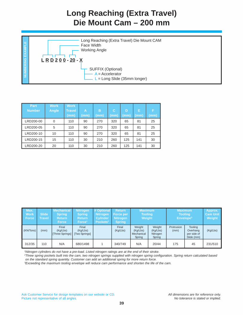
Part Work WorkNumber Angle Travel A B C D E F
(mm) (mm) (mm) (mm) (mm) (mm) (mm)
LRD200-00 0 110 90 270 320 65 81 25
LRD200-05 5 110 90 270 320 65 81 25
LRD200-10 10 110 90 270 320 65 81 25
LRD200-15 15 110 30 210 260 125 141 30
LRD200-20 20 110 30 210 260 125 141 30
Long Reaching (Extra Travel)Die Mount Cam – 200 mm
Long Reaching (Extra Travel) Die Mount CAMFace WidthWorking Angle
SUFFIX (Optional) A = Accelerator L = Long Slide (35mm longer)
L R D 2 0 0 - 20 - X
NU
MB
ERIN
G E
XAM
PLE
Max. Mechanical Nitrogen # Optional Return Maximum Maximum Approx.Work Slide Spring Spring Nitrogen Force per Tooling Tooling Cam UnitForce Travel Return Return Cylinder Nitrogen Weight Envelope3 Weight
Force Force1 Pockets2 SpringFinal Final Final Weight Weight Protrusion Tooling
(KN/Tons) (mm) (Kg/Lbs) (Kg/Lbs) (Kg/Lbs) (Kg/Lbs) (Kg/Lbs) (mm) Overhang (Kg/Lbs)[Three Springs] [Two Springs] Mechanical Nitrogen per side of
Spring Spring Slide (mm)
312/35 110 N/A 680/1498 1 340/749 N/A 20/44 175 45 231/510
1Nitrogen cylinders do not have a pre-load. Listed nitrogen ratings are at the end of their stroke.2Three spring pockets built into the cam, two nitrogen springs supplied with nitrogen spring configuration. Spring return calculated based on the standard spring quantity. Customer can add an additional spring for more return force.3Exceeding the maximum tooling envelope will reduce cam performance and shorten the life of the cam.

40
Ask Customer Service for design templates on our website or CD. All dimensions are for reference only.Picture not representative of all angles. No tolerance is stated or implied.
Calculation of Load and Stroke
P
S1
Q
L
Θ1
Θ2
S
VF
S1
STROKE DIAGRAM
S
Θ1
Θ2
L
Θ1
P = F x cos
sin ( )Θ2+Θ1
Q = F x 1
sin ( )Θ2+Θ1
V = F x 1
tan ( )Θ2+Θ1
L = S xsin ( ) cos
Θ2+Θ1
Θ1
S1 = S x cos
cosΘ2
Θ1
S = S x cos
cos Θ2
Θ1
DRIVING ANGLE OF INCLINATIONWORKING ANGLE
F FORCE REQUIRED (PIERCING/TRIMMING/FLANGINGFORCE + PAD FORCE + SPRING RETURN FORCE)
P PRESS FORCEV LOAD ON SLIDING SURFACE OF DRIVERQ LOAD ON SLIDING SURFACE OF SLIDES WORKING STROKES1 SPRING STROKE (SLIDE TRAVEL)L PRESS STROKE
Θ2
Θ1

IEMwww.danly.com
AERIAL & DIE MOUNT CAMS
The IEM Value PropositionI. IEM is recognized as the leader in manufacturing quality die sets and related products to
the global parts forming industry. Our reputation has been built by satisfying customer needs,and we are very strong in the automotive and appliance industries.
II. IEM offers outstanding delivery on a consistent basis. Choosing us as a supplier meansthat our customers have a competitive advantage in delivering their products to the market.
III. IEM has complex machining capabilities on die sets at several strategically located facilities.Various locations means lower shipping costs and allowing IEM to machine complex diesets means the customer’s machining centers have additional capacity.
IV. IEM’s vast breadth of products assures innovative solutions. We strive to address customerproblems by utilizing our research and development department as well as other technicalprofessionals.
V. IEM has a technically trained sales force and distributor channels with engineering support.Sales, marketing and engineering professionals are available to support our product lines.
...A LEADING MANUFACTURERAND INNOVATOR OF DIE SETS
AND DIE COMPONENTSSUPPLIED GLOBALLY TO THEMETAL FORMING INDUSTRY...
Competitive PricesReliability and Performance
High Quality Design & ConstructionOutstanding Service & Support
IEMwww.danly.com
AERIAL & DIE MOUNT CAMS CATALOG
© 2011 IEM. All rights reserved. DS400-2 REV 03/11
Distributed by:
WITHIN THE USA & CANADACALL: 800-652-6462FAX: 800-406-4410
OUTSIDE THE USA & CANADACALL: 001-248-489-7816FAX: 001-248-553-6842
IEM
The Anchor Danly Company