ifatca the controller - january 1964
DESCRIPTION
ÂTRANSCRIPT


TELEFUNKEN radar for safe
guidance from take-off to landing
TELEFUNKEN
I FAT CA JOURNAL OF AIR TRAFFIC CONTROL
THE CONTROLLER Frankfurt am Main, January 1964 Volume 3 · No. 1
Publisher: International Federation of Air Traffic Controllers' Associations, Cologne-Wahn Airport, Germany.
Officers of IFATCA: L. N. Tekstra, President; G. W. Monk, Executive Secretary; Maurice Cerf, First Vice President; Roger Sad et, Second Vice President; Hans W. Thau, Hon. Secretary; Henning Throne, Treasurer; Walter Endlich, Editor.
Editor: Walter H. Endlich,. 6471 Rommelhausen, Wilhelmstrasse 10, Phone Frankfurt 20821.
Production and Advertising Sales Office: W.Kramer &Co., 6 Frankfurt am Main NO 14, Bornheimer Landwehr57a, Phone 44325, Postscheckkonto Frankfurt am Main 11727. Rate Card Nr. 1.
Printed by: W.Kramer&Co.,6 Frankfurt am Main N014, Bornheimer Landwehr 57a.
Subscription Rate: DM 8,- per annum (in Germany).
Contributors are expressing their personal points of view and opinions, which must not necessarily coincide with those of the International Federation of Air Traffic Controllers' Associations (IFATCAJ.
IFATCA does not assume responsibility for statements made and opinions expressed, it does only accept responsibility for publishing these contributions.
Contributions are welcome as are comments and criticism. No payment can be made for manuscripts submitted for publication in •The Controller·. The Editor reserves the right to make any editorial changes in manuscripts, which he believes will improve the material without altering the intended meaning.
Written permission by the Editor is necessary for reprinting any part of this Journal.
Advertisers in this Issue: The Decca Navigator Co., Ltd. (2). Decca Rodar Ltd. (Bock Cover) The Marconi Co. (15, 16). N. V. Nederlondse Signoolapporoten (Inside Bock Cover). Telefunken AG (Inside Front Cover). Picture Credit: City of Brussels (12). Hazeltine Corp. (6, 7, 8, 9, 10)
CONTENTS
Controllers and Conversing Computers
James E. Grambart
Recent Developments in Helicopter IFR Operations
Tirey K. Vickers
ICAO RAC/OPS Meeting
Maurice Cerf
Brussels invites you
Symposium on Electronics Research and Development for Civil Aviation
G. W. Monk
3
6
11
12
13
I say, Humphrey, look at that simply marvellous
aeroplane. How madly fast it's Hying.
And there's another one over there- and there- and there
Do you suppose they know where they're going?
Crazy man. of course there's a frantic genius in that control tower place taking care of all that
Like poor Cuthbert, my controller cousin,
who was wafted screaming to a clinic?
You'd think there was an easier way ...
. .. There is!
The precise push-button
navigation system with
air traffic control data link
Controllers and Conversing Computers* By James E. Grambart Human Factors Branch
NAFEC
While research and development work proceeds on the Supersonic Transport, it is becoming clear that the 1970-75 air traffic control system design should be predicated, at least in part, by the control requirements of supersonic flight. This article gives a clearly authoritative, although unofficial view of what kind of automation the system is likely to need then, and how it will do its job.
Author Grambart made his first solo flight in an OX-5 powered Waco 10 back in '31, when he was a line boy al the Jamaica Sea Airport. In 1941, he joined the RAF. Following Pearl Harbor, Mr. Grambart put in time with the Pan-American ferry program and the civil pilot training program. Traffic control work began as a trainee at Richmond tower, and since then he's worked in various facilities, topped with nine years at Laguardia Tower where he •never worked harder, or felt more useful.· This experience got him thinking about the potential of automation, and he transferred to the ARDS in 1961. He now works with the Human Factors branch of the Research Division, under Dr. E. Buckley in the development of optimum display criteria.
The purpose of this paper is to discuss some aspects of automated control as applied to the forthcoming Supersonic Transport. Readers are warned that, in some quarters, the writer is considered a permanent resident of cloud nine. In that context the opinion set forth should be considered wholly his own. - the author
The Technical Journals seem to agree that the SST will probably reach operational status between 1972 and 1975, with prototype testing in the late sixties. Major decisions on the U.S. effort are scheduled to be made this year. The combined French/English effort is already underway and it would be unlikely that the Russians are not working full time on their own SST program. There is an under-current of wishful thinking that the vehicle should wait an additional decade because of the potential of runaway equipment competition and the overcapacity that it breeds. However, the inexorable advance of technology rarely waits upon the cautions of the cost accountant. It is just a matter of who will produce a commercially practical SST first.
While the Anglo-French machine may cruise at Madi 2._2 it is probable that the advent of more powerful engines, combined with steel airframe construction, will boost speeds to the Mach 3-3.5 range. We can, then, reas_onable anticipate a vehicle that will cruise at something like 1,800 statute miles per hour, a 330% increase over the present sub-sonic jets. At one mile every two seconds the airplane will be cruising at the muzzle velocity of a Garand rifle bullet. Try translating that into target movement on your ARSR scope!
Because the high cruising speed will dictate a large power-to-weight ratio, the SST should take off in less distan_ce than the present jets. Wing loadings at landing we1g~t should be comparable with present values, This, combined with expected improvement in high lift, high drag devices, perhaps even blown flaps or boundary layer control, should limit the new beast to present approach speeds and roll-out distances. The enormous thrust will
• Reprinted from ATCA's JOURNAL OF AIR TRAFFIC CONTROL with kind permission of the Editor.
permit climb angles and rates which should minimize public objection to the more powerful engines. Actually, the climb angle will be limited largely by passenger comfort. To facilitate anti-noise climb-out, perhaps the seats coufd be gimballed so that the bemused passenger could study the cabin carpet as the fuselage floor swung steeply toward his face in a sixty degree climb!
Airborne Automation
The subsonic transport, in the climb-cruise-descent regimes, is rarely hand-flown because of the fuel savings and increased schedule keeping accuracy made possible by the precision of the auto-pilot. It is estimated that 55-60% of the SST direct operating costs will be chargeable to fuel. Since fuel load and payload are closely related, the fuel savings and scheduling accuracies attributable to the auto-pilot will make auto flight even more desirable for the SST. The term "Auto Flight" is used to describe combined automatic navigation and attitude control as permitted by an integrated self-contained navigation and auto-pilot system.
It is the writer's opinion that the great speed, enormous fuel consumption and very high cruise altitudes of the SST (60 to 80 thousand) will almost surely rule out primary reliance upon ground-based radio aids except for take-off and landing. Rigorous fuel economy considerations will dictate great circle navigation for all long distance flights. Fortunately there are in being (and in use) two self-contained navigation systems (SECONS) which permit automatic and programmable Great Circle navigation and which are almost, but not quite, independent of ground radio aids. The brain of both systems is
the electronic computer. The Dopler Navigator pulses radio energy toward
the ground along the lateral and longitudinal axis of the aircraft and listens for a returned echo. Minute frequency differences between transmitted and reflected energy (Doppler Shift) permit accurate sensing of ground sp~ed and drift angle. Today the Doppler Navigator is coming into its own. It is particularly useful for, but by no means limited to, over-water jet operation. .
Like its Doppler cousin the more sophisticated Inertial Navigator may be described as an automa~ed dead reckoning system. A "stable-table" is space-oriented by three gyros with axes at right angles to each other. The table will maintain the local vertical regardless of the aircraft's attitude or geographical position. Micro-accelerometers, capable of sensing millionths of c1 G, are mounted on the table along the three major axes of the aircraft. So mounted, they sense inertial loads imposed by the slightest speed change along any axis. The heading
3

reference of the stable table together with the output of the accelerometers and a real time source is fed into the system's computer. Acceleration multiplied by time equals speed, and speed multiplied by time equals distance covered. The computer does this arithmetic (like crazy!) to provide the pilot a continual readout of ground speed, drift angle and distance remaining. Unlike the Doppler system, the Inertial Navigator may be expected in future to provide an altitude and vertical speed readout quite
free of barometric vagaries. Also unlike the Doppler, tlie Inertial Navigator will work in any medium, including water. If any of you scope watchers are still wondering how the nuclear subs are able to operate for long periods beneath the Arctic ice and still split the North Pole, Dr. Charles Draper's brain child, the Inertial Guidance System is your answer.
SST and ATC
Having briefly discussed probable performance characteristics and navigation necessities of the SST, let us try to foresee some aspects of its ATC enviroment. Remember we are dealing now with the time interval 1972-75. It is reasonable to assume that a major part of the indevelopment National Airspace Utilization System will then be operational. Individual items would include:
~ Unbroken radar coverage on all major routes and at all flight levels.
D>- Mosaic radar displays to combine several antennae inputs into a single large and variable presentation.
~ Alti-coders to provide radar target height/identity data.
Iii>- Radar trackers to continuously tag selected targets with pertinent alpha-numeric data derived from the alti-coders.
g:... Computer-generated electronic tabular displays of flight plan data, automatically updated.
Iii>- Computer generated and .displayed conflict predition and resolution.
~ Computer-aided terminal area sequencing.
~ An all-weather automatic or semi-automatic landing system.
laP- Airspace segregation on an aircraft-performance and pilot-capability basis.
Processed Radar and Data Link
The above is an imposing and encouraging degree of
projected system improvement. It should certainly enable the controller to cope safely and efficiently with most of the traffic load foreseen for the period under consideral ion. However it is humbly suggested that two major additions are required to enable him to deal with special problems posed by that guided missile, the SST. The first of these is Processed Radar. The second is Data Link.
Processed Radar (PRORAD) is obtained by feeding radar from one or more sites to an ATC computer. Coverogc from multiple radars and a single aircraft is resolved lo provide a single target return on a priority return basis.
4
The alti-coder transponder returns provide height/identity data. The data is integrated with a real time input, drumstored, and displayed as alphanumerics tagged to the target on a Charactron tube, and/or on an associated electronic tabular display. The important thing to know is that the computer, in addition to displaying the ground velocity and positional data, remembers it. Similarly, the computer can be programmed to process and remember all relevant target data in a particular environment and to display information for any particular altitude strata, permitting vertical sectorization.
Data Link is an automatic or semi-automatic airgound-air communication system wherein data is digitized and transmitted as a pulse train of information bits. Such data is transmitted thousands of times faster than a spoken message, enormously increasing the efficiency of frequency utilization and helping to conserve what remains of the unused spectrum. The received data can be displayed to the pilot as alpha-numerics on a small Charactron tube. The pulse train transmitted by an altimetercoded transponder (alti-coder) is a form of Data Link.
We referred briefly above to the fact that neither Doppler nor Inertial Navigators are quite independent of ground radio aids. Because they have system errors which are accumulative with time (random wander rates) they will gradually get out of geographical alignment. Anyone who has done dead reckoning knows that his error increases with time from his last known geographical fix. These automated dead reckoning systems must be periodically informed of their real position. They can be reset manually from another information source or they can incorporate automatic fix correcting equipment which does the job by sampling inputs from a star tracker, VOR/DME or Loran C Sensors. However most of the correction is done manually. Because often long periods must elapse before an accurate correcting fix can be obtained, the navigation systems must be built to the nth degree of accuracy to minimize the random wander rate. But there is a method of fix-correction, yet to be explored, which may provide almost constant, accurate fix updating.
Air-Ground Computer Cooperation
We all know that automatic data exchange between business computers via leased telephone line is an established and increasingly used DATA-LINK technique. What are the navigation and control possibilities in the SST air traffic enviroment? Let's suppose that both the airborne navigation computer and the radar-processing master ATC computers are equipped with a Data-Link transceiver. Assume that the ATC computer is programmed to convert slant-path radar data (it has target altitude from the
alti-coder) to true range and azimuth data, and to convert
this in turn to X-Y coordinates. Assume that the master computer is further programmed to transmit this processed
postion data at prescribed intervals, addressed via the
identity feature of the alti-coder, to the correct aircraft.
The received data will permit the navigation computer to realign itself with the real world at very short intervals,
holding the cumulative error to near zero. A suitable
warning would alert the pilot to any large scale machine realignment which would indicate either a gross error in the navigation system itself, or the reception of an incorrect position from the Radar Processor.
The above technique, while useful over land masses, could obviously not be used for overwater flights outside of present radar range. But it is probable that the SST, flying at its great altitudes, would rarely if ever be out of range of a network of long-range, ocean scanning radars which could be integrated with a master ATC computer. This computer, equipped with a single sideband transceiver, could fix-update the overocean flights via Data Link even at long ranges.
With such a system of automatic fix updating, autonavigators would not need to be manufactured to expensively close tolerances and it would permit true area navigation-quite free of airway restriction or reliance upon airway radio aids for fix updating. Great circle flight presupposes area navigation. Area navigation based upon reliable navigation aids will permit multi-channel routings of same-direction traffic; will allow us to spread out the traffic instead of crowding it into narrow airways.
Getting more from the System
Meanwhile, back at the ranch, the master ATC computer is busy sampling, processing, displaying and transmitting radar position data. Remember that through radar inputs it can know and retain the complete control picture: range, azimuth, altitude, velocity and time (X, Y, Z, V and T) for all alti-coder equipped traffic, and it will be programmed to perform memory search and computation to provide and display conflict detection and resolution.
Let us simultaneously increase the capability of the airborne self-contained navigation system. Mr. Walter Fried of General Precision Laboratory has suggested that these units can be equipped with an "ETA Zero Reader". Since fuel consumption of the SST will be such that its approach time slot at destination should be known and, as far as possible, guaranteed before take-off, such an instrument will be enormously helpful to the pilot in precisely meeting his ETA.
Here is how the ETA Zero Reader would work. Essentially a "slow-fast" time indicator integrated with the auto-navigator, it would be centered on the planned ETA at take-off. Thereafter the autonavigator would generate throttle setting signals via the auto-pilot servos to keep
the ?irc::raft on the desired schedule. The pilot, observing the 1nd1cator, would have a constant running check on his schedule status. And just incidentally, so would the ATC computer, by continuously tracking the radar target.
Computer Control
Having beefed up the ro~e of both the autonavigator and the Master ATC Computer, they can be tied into a cooperative computer complex via Data Link. Since this
env1s1ons a man-supervised, machine-to-machine experimental system it opens up new possibilities in the realm of ATC automation. Like any experiment it should progress from the simple to the complicated. Our simple test environment would be the lightly populated SST cruise
altitudes.
Here's how the system would work. Assume that two supersonic transports at cruise altitudes are on courses converging toward a potential conflict. The master ATC computer, sampling radar inputs (X, Y, Z, V and T) analyzes the situation and displays it to the controller. It also generates an optimum conflict resolution and displays it graphically along with the proposed clearance message. The controller approves the machine-generated clearance, pushes a "send" l:tutton, and the Data-Link, addressing the message vi:; the alticoder identity feature, transmits it to the correct airplane. The clearance is displayed to the pilot via a small rectangular Charactron tube and also stored as maneuver instruction in the navigation computer. The pilot complies with the clearance by depressing an "execute" button and the autoflight system c:ompletes the control instruction. Both pilot and controller remain in the loop as active supervisors of a machine system.
Automated Collision Avoidance
A Data-Linked, man-supervised cooperative computer system promises formulation and execution of ATC instructions at a rate commensurate with the enormous velocities of the SST. It means that this fuel-guzzling vehicle will have the required precise schedule-keeping and freedom from delay. But the heart of the system is the master computer, informed of the dynamics of all controlled aircraft by processed radar and flight data inputs. A participating aircraft need not have an auto-flight system to benefit from this ground-based collision avoidance system. The only additional equipment required is (1) the Alti
coder and (2) a Data-Link receiver with suitable readout.
The pilot would acknowledge by voice as he manually
complies with the clearance.
The system described is only the logical extension of a new, explosively expanding machine age. Compared to present computer technology, we are in the position of the hand-weaver when Watt produced his steam engine. The creation of a fully automated ATC network will call for an overwhelming amount of systems engineering. But the creation of a modernized ATC system is a tremendous job and requires uninhibited thinking. There will be people to say that the proposed system is beyond our capacity. However - man has always overestimated his short term capability while seriously under-estimating his long-term potential. The cost will be great, but so ore the rewards,
and progress never carries a bargain price tag.
* * *
Don't miss it
5

Recent Developments in Helicopter I FR Operations by Tirey K. Vickers
Hazeltine Corporation Fig . 1 VERTOL V-107 He licopte r, p ossing Uni ted Na tions Building.
Some of the most interesting pioneering work in the field of flight operations today, is being accomplished by one of the shortest scheduled a ir lines in the world. The airline is New York Airways. Their pioneering is all a imed at the goal of becoming the first helicopter air car rier to obta in a supplementary FAA certificate for instrument flight operations.
Lack of instrument flight capabi lity has been costly. In summer, NYA's 25-passenger twin-engine Verto l V-1 07 he licopters may shuttle 27,000 passengers a month, between ld lewild, Wall Street, and N ewark. But winter is a d ifferent story . Last winter, NYA had to cancel 190/o of its schedules because of wea ther. The economic effect of these cancellations was even worse, because of a fi ck le factor known as passenger loya lty. NYA has found that after a prolonged interruption, passenger loads just don't jump back to normal when the helicopters start flying again - sometimes it takes several days. A lthough schedule dependability is desirable for any airline, it's critically important to NYA, whose potential competitors (taxi cabs) number in the thousands.
So th is year, NYA is doing something about the weather. However, IFR certification isn 't something w hich can be achieved overnight. In this case, it involves the unprecedented task of certifying the pilots, the helicopters, and even the navigation system. The actual tests started last spring and are expected to take about a year.
The program is important to U. S. aviation, because it has finally g iven the FAA a reason to develop IFR criteria for helicopter o perations. (Up to now, hel icopter operations have been sub ject to a number of fixed-wing regu lations.)
The program is important to cont ro llers, because one of its basic concepts, the use of precise pictorial navigatio n, cou ld point the way someday to a major si mpl ification of air traffic control procedures.
Technical Problems
W ith commercial jet transports abo ut to achieve a ll
weather capabi lity, why ha.ve the slow, d~cile2 whirlybirds
remained, for years, essential ly VFR machines . . For one thing, hel icopter design has had to wa it for
the comparatively recent development of the compact,
6
high-power, low -weight, gas turb ine, before anyone could market a commerc ia l mult i-engine helicopter with acceptable one-engine-out performance. But the re have been other problems.
Almost every helicopter ever bui lt has been lacking in aerodynamic stability. If its attitude is d isturbed, the typical copter shows no particular tendency to return to straight and level flig ht - in fact, it may tend to diverge even more. As a result, constant corrective action on the controls is required . This makes it fatiguing to fly for long periods - and espec ially on inst ruments.
The latter prob lem has been pro longed by the technica l lag in develop ing special instrumentation for low speed fl ight. Up to now, hel icopters have been forced to use flig ht instruments which were origina lly developed for fi xed-wing aircraft. Helicopter pi lo ts complain that these instruments are not easy to interpret and follow, in hovering or low-speed operations.
The IFR w inter hazard of icing can have an especially serious effect on he licopters, in fhat an unequally-balanced bui ld-up on the w hirling rotor b lades can lead suddent ly to a cri tica l vibration problem.
Another l imitation has been that the VHF and UHF navigation systems presently in use are sub ject to li neof-sight cutoff prob lems, in some of the most important min imum-alt itude a reas desi red for helicopter operat ions. These systems a lso lack flexibi lity, due to the siting problems which exist around bui lt-up metropol itan a reas.
N ew York Airways now has a tentative solut ion to each of these technica l problems. The object of the IFR certificat ion program is to demonst rate conclusive ly to the FAA, that all these solution a re adequate.
Engine-Out Capability
As sho wn in Figure 1, the Vertol V-107 has two rotors . They are geared together, through a common drive shaf t, to turn in opposite di rections. The shaf t is powered by two Genera l Electric gas turb ine eng ines, presently rated a t 1250 horsepower each. Th e eng ines are connected to the rotor drive through indiv idua l overrunning (freewheel ing) c lu tches. Should one eng ine suddenly fai l, its clutch in stantly goes into free-whee ling . The live engine can then assume the entire job of powering the rotor blades, with -
a:: w 3: 0 a..
0
POWER REQUIRED
- - - POWER AVAILABLE
·1 POWER AVAILABLE FOR &.....;..;,;,......._-'--"--':: SINGLE-ENGINE CLIMB
2 ENGINES ---------
SINGLE ENGINE SPEED
OPTIMUM SPEED
SPEED
MAXIMUM SPEED
I ENGINE
MAXIMUM CRUISE SPEED
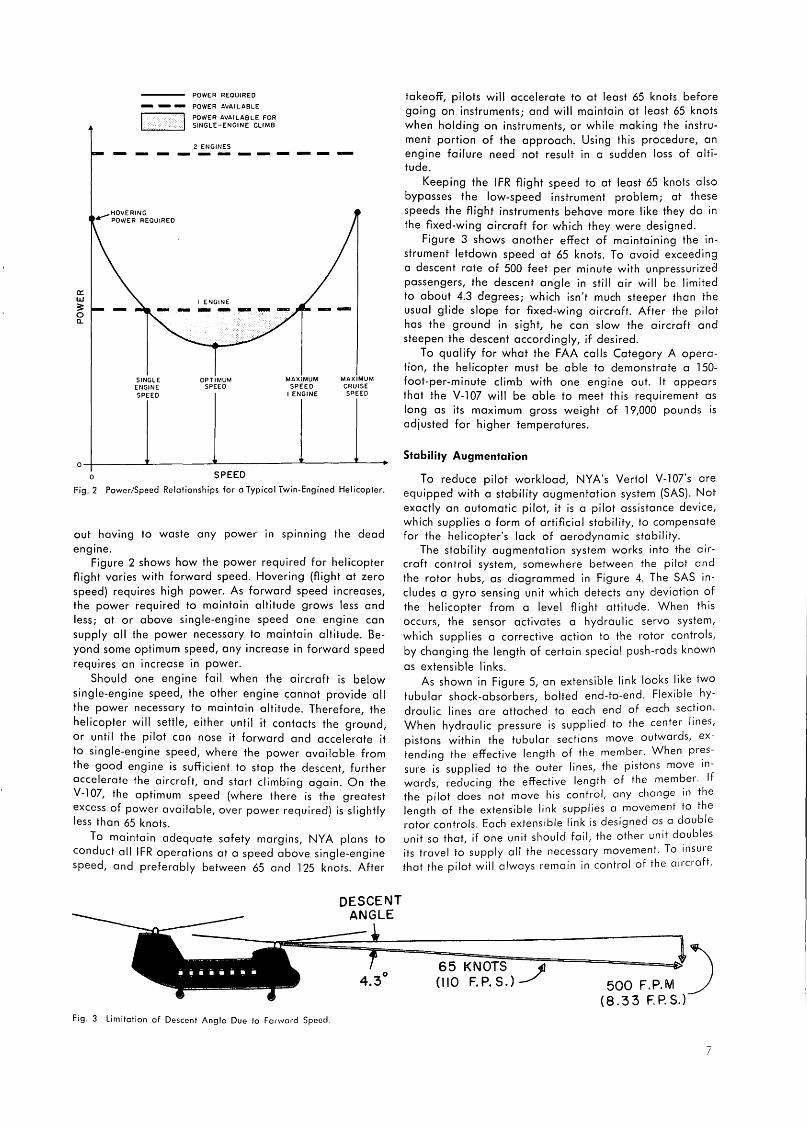
Fig. 2 Power/Speed Relationships for a Typical Twin-Engined Helicopter.
out having to waste any power in spinning the dead engine.
Figure 2 shows how the power required for helicopter flight varies with forward speed. Hovering (flight at zero speed) requires high power. As forward speed increases, the power required to maintain altitude grows less and less; at or above single-engine speed one engine can supply all the power necessary to maintain altitude. Beyond some optimum speed, any increase in forward speed requires an increase in power.
Should one engine fail when the aircraft is below single-engine speed, the other engine cannot provide all the power necessary to maintain altitude. Therefore, the helicopter will settle, either until it contacts the ground, or until the pilot can nose it forward and accelerate it to single-engine speed, where the power available from the good engine is sufficient to stop the descent, further accelerate the aircraft, and start climbing again. On the V-107, the optimum speed (where there is the greatest excess of power available, over power required) is slightly less than 65 knots.
To maintain adequate safety margins, NYA plans to conduct all IFR operations at a speed above single-engine speed, and preferably between 65 and 125 knots. After
Fig. 3 Limitation of Descent Angle Due to Forward Speed.
takeoff, pilots will accelerate to at least 65 knots before going on instruments; and will maintain at least 65 knots when holding on instruments, or while making the instrument portion of the approach. Using this procedure, an engine failure need not result in a sudden loss of altitude.
Keeping the IFR flight speed to at least 65 knots also bypasses the low-speed instrument problem; at these speeds the flight instruments behave more like they do in the frxed-wing aircraft for which they were designed.
Figure 3 shows another effect of maintaining the instrument letdown speed at 65 knots. To avoid exceeding a descent rate of 500 feet per minute with unpressurized passengers, the descent angle in still air will be limited to about 4.3 degrees; which isn't much steeper than the usual glide slope for frxed-wing aircraft. After the pilot has the ground in sight, he can slow the aircraft and steepen the descent accordingly, if desired.
To qualify for what the FAA calls Category A operation, the helicopter must be able to demonstrate a 150-foot-per-minute climb with one engine out. It appears that the V-107 will be able to meet this requirement as long as its maximum gross weight of 19,000 pounds is adjusted for higher temperatures.
Stability Augmentation
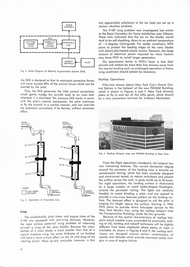
To reduce pilot workload, NYA's Vertol V-107's are equipped with a stability augmentation system (SAS). Not exactly an automatic pilot, it is a pilot assistance device, which supplies a form of artificial stability, to compensate for the helicopter's lack of aerodynamic stability.
The stability augmentation system works into the aircraft control system, somewhere between the pilot and the rotor hubs, as diagrammed in Figure 4. The SAS includes a gyro sensing unit which detects any deviation of the helicopter from a level flight attitude. When this occurs, the sensor activates a hydraulic servo system, which supplies a corrective action to the rotor controls, by changing the length of certain special push-rods known
as extensible links. As shown in Figure 5, an extensible link looks like two
tubular shock-absorbers, bolted end-to-end. flexible hydraulic lines are attached to each end of each section. When hydraulic pressure is supplied to the center lines, pistons within the tubular sections move outwards, extending the effective length of the member. When pr~ssure is supplied to the outer lines, the pistons move in
wards, reducing the effective length of the mem~er. If the pilot does not move his control, any change in the length of the extensible link supplies a movement to the rotor controls. Each extensible link is designed as a double unit so that, if one unit should fail, the other unit doubles its travel to supply all the necessary movement. To insure that the pilot will always remain in control of the aircraft,
65 KNOTS _JJ ( 110 F. P. S. ) 500 F.P.M )
( 8. 3 3 F. P. S.)
7
ROTOR CONTROLS
r---------;~----- --, I I I I I
1 .--~~~
I A~~~TS~~E HY~~~~~IC EXTEN SIBLE
I GYRO SYSTEM LI NK
I L---------- ------ _ _ _ J
COCKPIT CON TROLS PIL OT
Fig. 4 Block Diogrom of Stabili ty Augmenfofion System (SAS).
the SAS is designed so that its maximum corrective forces will never exceed 30% of the control forces which can be exerted by the pilot.
Thus, the SAS generates the little control corrections which gent ly mudge the aircraft back to an even keel whenever it is dis turbed. Yet, because SAS works in series w ith th e pilot's control movements, the pilot continues to Ay the a ircra ft in a normal manner, and can override the automa tic corrections if he desires, without conscious effo rt.
ROTOR CONTROLS
LEGEND
D FLUID UNDER PRESSURE
® I COCKPIT /I CONTROLS
0
Fig . 5 Operation of Extensible link.
Icing
ROTOR CONTROLS
The windss hields, pitot tubes, a nd engi ne inlets o f the V-107 are equipped with anti-ici ng devicyes . However, the most serious potential icing p ro blem o f rotorw ing aircraft is icing of the rotor blades. Because the crosssection of a rotor b lade is much sma ll er than that of a typical airplone wing, the same thickness of ice bui ldup will hove a more cr itica l effect on the l ift and drag of the rotating airfoil. More quickly noticab le, however , is th at
8
any appreciable unba lance in the ice load con set up a serious v ibration prob lem.
The V-107 icing problem was investigated lost winter at the Roya l Ca nadian A ir Force installat ion near Ottawa. These tests indicated that the ice on the b lades w ould tend to be self-sheddi ng, dow n to a n ambient temperature of -4 degrees Centrigrade. For colder conditions, N YA plans to protect the leading edges of the rotor b lades with electrically-heated plastic covers. However, the large amount of electrical power required for these heaters may force NYA to install larger generators.
On operat ional factor in NYA's fovor is tha t the ir aircraft will seldom be more than five minutes away from the neo;est landing pod; so prolonged operat ion in heavy icing conditions should seldom be necessary.
Rooftop Operations
Fifty-nine storeys above New York City 's Grand Centra l Station is the hel iport of the new PANAM Bu ilding, which is shown i n Figu res 6 and 7. New York Ai rways plans to Ay in and out o f th is lof ty perch, which should be a very conve ni ent terminal for midtow n Manhattan .
Fig. 6 Rooftop Heliport atop new PANAM Build ing in N ew York.
From the fli ght opera tions sta nd po int, the hel iport has two interesting features. The curved hor izontal edging around the perimeter o f the land ing area is actually an aerodynamic fa iring, which has been carefully designed a nd wind-tunnel tested, to red uce turbulence and smoo th the airflow acro ss the roof, in gusty wi nds up to 50 knots. For ni ght opera tions, the landing surface is i lluminated by a large num ber of smal l bul let-sha ped floodlights, aro und the perimeter roi l ing. The lights ore carefull y hooded, to avoid blinding a pi lot; and are spaced to provide a cr iss-cross textured pattern on the landing surface. The textured effect is desig ned to aid the pilot in judging his height above the surface. Start ing in 1964, NYA plans to p rovide d irect he l icopter service to the N ew York World's Fa ir, using the rooftop hel iport atop the Transportat ion Building, inside the fa ir grounds.
Because of the spatia l characteristics of roo ftop heliports (sma ll useab le areas suro unded by pract ically nothing a t a ll), landing and takeoff techniques wi l l be slightly different from those employed where plenty o f room is ava ila ble. A s shown in Figures 8 and 9, the rooftop techniques a re designed around certa in combinations of speeds and alt itudes which provide maximum safety marg ins in case of engine fai lure.

II
Fig. 7 Landing Surface and Perimeter Lighting Installation of PANAM Rooftop Hel iport.
DECISION HEIGHT
120-150 FEET
j
PILOT MAINTAINS AT LEAST 35 KNOTS DOWN TO LANDING DECISION POINT, 120-150 FEET ABOVE LANDING PAD. THIS PROCEDURE PROVIDES AMPLE CLEARANCE FOR RECOVERY TO SINGLE-ENGINE SPEED IN CASE OF SUDDEN ENGINE FAILURE.
HEIGHT LOSS
t 48
KNOTS SINGL E ENGINE SPEED
65 KNOTS
Fig . 8 Rooftop Land ing Procedure.
f tUJ:: : : : : : : : : :
I® I WITH ENGINE FAILURE
VERTICAL - PRIOR TO REACHING 8 CLIMB AT PILOT CAN RETURN TO LANO AT A 1000 FPM
TO WITH ENGINE FAILURE AT OR DECISION AFTER REACHING 8, PILOT CAN HEIGHT ACCELERATE TO SINGLE-ENGINE
115 FEET SPEED ANO BEGIN CLIMBOUT
I 111111 II 11 J II · ,~,, I II 111111 II I
Fig. 9 Rooftop TokeoA' Procedure
SINGLE ENGINE SPEED
48 KNOTS
35 FEET CLEARANCE ABOVE TAKE OFF ELEVATION
L
9

Pilot Certification
Most NYA pilots have had their fixed-wing instrument ratings for years. One of the primary tasks in the IFR certification program has been to draw up a course of training to enable these pilots to qualify for their helicopter instrument ratings. NYA, FAA, and the Air Line Pi lot's Association have all furnished ideas for this training program. The test is equivalent in scope, and required proficiency, to an FAA test for a fixed-wing rating in a twin-engine turboprop transport aircraft. The helicopter flight test includes single-engine operation as well as flight with SAS inoperative.
As no suitable helicopter flight simulator is available, all training is being conducted in the actual aircraft. Qualification of NYA's 30 pilots is expected to require about 500 total flight hours. NYA hopes that these tests will result initially in authorized weather minimums of 300-foot ceiling and 1/i-mile visibility; with a possible reduction to 100-foot ceiling and ' /•-mile visibility at some distant date.
Navigation System
Requirements: It isn't often that an airline has to supply its own navigation system, but NYA had to do it. Its special requirements for low-altitude navigation, around the concrete canyons of the New York area, could not be
met by available U.S. systems. NYA needed a navigation system which would provide
sol id coverage, without reflections, clear down to the ground, in an area characterized by the largest collection of tall buildings in the world. They needed extremely accurate navigation, to find their way precisely to tiny pads like the PANAM and Wall Street Heliports. They needed an extremely flexible method of navigation, to follow pre-defined curved tracks which would avoid high obstacles and stay clear of the approach and departure lanes of fixed-wing aircraft.
NYA needed a system which would provide closelyspaced parallel tracks so they could fly simultaneous schedules in opposite directions, at a single minimum-altitude flight level. They needed area coverage so they could modify their route structure and add additional terminals as desired, without having to relocate ground facilities or add new ones. And, because piloting a helicopter requires both hands and both feet, NYA needed a navigation system which would show the pilot exactly where he was, at all times, without having to shuffle charts or twist knobs.
So they got Decca. The ground stations of the New York Decca chain are
operated by a subsidiary of New York A irways, and are monitored continously by recorders installed in NYA's flight operations office at LaGuardia Ai rport.
NYA's helicopters are all equipped with dual installations of the Decca Mork 8-A receivers and Flight Logs, as shown in Figure 10. During the course of the certification program, the reliability of the a irborne equipment has been increased tremendously by the adoption of a new solid-state digital computer (in place of the former ana
logue computer) to drive the Flight Log. Around New York VFR helicopter approaches and de
partures are often made at right angles to the fixed-wing runway in use. Keep ing helicopters out of the stream of fixed-wing traffic is advantageous from the ATC stand-
10
Fig. 10 Dual DECCA lnstallalian in New York Airways VERTOL V-107 Helicopter.
point, as thei r relatively low forwa rd speed could tie up an approach o r departure path for a considerable period. With Decca, there is no part icular reason why NYA's instrument flight paths should differ from those normally used in VFR weather. System accuracy on NYA's present routes will perm it a pilot to navigate about as accurately on instruments, with a Flight Log, as he can in visual flight conditions using familiar neighborhood landmarks.
Significance for ATC - Although most people don't associate navigation with today's critical ATC problems, the character istics of the present navigation system have a pronounced effect on the efficiency of the a ir traffic control system. Having just completed a study concerned with finding a suitable site for a new major airport in the New York metropo litan a rea, the w riter is painfully aware of the restrictions w hich are imposed on 3-dimensional traffic flow by the present singletrack ai rway system and its radial col l ision cou rses.
To handle increasing traffic, radar controllers have had to compensate for these limitations by assuming more and more of the navigationa l responsibility themselves. However, the widespread employment o f a ir route radar vectoring procedures has greatly increased the controller workloads of ta rget track ing, communication, and coordination. Sometimes, as in the New York area on June 7 1963, th e total work load bu ilds up to the point wher~ severe flow restrict ions must be imposed; the result is reduced capacity, and monumental delay stat istics.
Could a high-accuracy navigation system, with pictoria l presentat ion for the p ilot, reverse this current trend towards more controller workload per aircraft? Previous ATC research has shown that the use of parallel dual- lane airways, in place of today's single-track diverging-converging routes, will e liminate much of the control workload and congestion presently encountered on busy climb and descent segments.
Pictorial navigation, on parallel multi -track coded routes, promises a ma jor reduction in controller workload, by providing more mutua lly non-i nterfering flight tracks, and then giving pilots the capability of following them accurately through congested areas, without control ler assistance. He re perhaps is the most significant gain that any future system improvement could make, towards increasing the capac ity of tomorrow's air route network.
ICAO RAC/ OPS Meeting, Montreal, May 1963 Maurice Cerf lst Vice President, IFATCA
As an international and aeronautic organization, ICAO owed it to themselves to choose, for their permanent headquarters, a city both air minded and sufficiently cosmopolitan to accomodate the taste of their various members. Montreal meets these requirements as being the air lines center of a large country where air transport is part of the everyday life, on the other hand it is a many sided city at once British, American and French looking: there are British districts with pleasant detached houses, green lawns; French districts with old churches, picturesque narrow streets that make you think of provincial towns; the center is strikingly American with a flood of neon signs, busy streets, drug stores and gigantic buildings. When I add that, due to immigration, Montreal is a melting pot of European born people, you will understand that one has no difficulty in feeling at home at one place or another.
We, Air Traffic Controllers, are all concerned with the activities of ICAO; our professionnal life is deeply influenced by its decisions, therefore we most naturally consider ICAO with utmost reverence. IFATCA attributed a great importance to its participation to an ICAO meeting and you will remember that during our last annual conference in London, a long session was devoted to the study of the working papers IFATCA would submit to the RAC/OPS meeting. I left Paris for Montreal my brief case filled with these papers and my mind with the articles of document 4444, and annexes 2 and 11 which constituted the main object of the meeting.
ICAO occupies most of the Aviation Building in the central section of Montreal, when I went there for the first time I had the pleasant surprise of seeing a great number of familiar faces belonging to those aviation experts who attend air traffic meetings all over the world; this simplified my introduction to ICAO.
The RAC/OPS meeting was divided into four committees, the fourth one convening only on the third week. Nineteen items were on the agenda and distributed among the different committees, you wiH immediately notice that it takes a four to five men delegation to cover the whole of the discussions. I had some moments of perplexity when two committees dealt with items of equal importance to I FATCA. The length of the discussions was another cause of worry, it was absolutely impossible to foresee the end of an item, some last minute objection being always possible with the effect of stretching the talks for, sometimes, another day.
At this point I would like to state that my task was rendered eomparatively easy by the wholehearted cooperation of several delegates and observers who kept me informed of the happenings when I could not be present, I would like to mention the friendly attitude of the Chairmen who took the trouble of sending for me when they wanted me to introduce one of our working papers.
What did IFATCA expect of this meeting? ICAO is an impressive organization, its recommendations are regarded with the highest respect in every country and, as it is in any assembly with its own habits and procedures, it is not considered wise for a newcomer to make himself too obvious during his first attendance so we decided to con-
centrate on the elaboration of working papers which, being distributed to all the delegates and observers, would spread the views of the Federation. I would, of course, be available to answer any question. I think this was the right thing to do as our papers were widely read and commented upon. I had to answer a lot of questions proving the interest they had raised. IFATCA succeeded in convincing delegates that its aims went towards a constructive cooperation. You should know that our attendance was regarded, at first, with a certain amount of reluctance, people were dubious about our designs, fearing that we would be just another pressure group whose purpose is to push new rules or amendments for the benefit of a determined category of people; it was a relief to find out that, far from that, we were willing to offer our cooperation for the improvement of Air Traffic Control.
This kind of approach which was to be my rule of conduct, did not prevent me, once I was more familiar with the place, from taking part in the discussions. I had first to introduce verbally our working papers to the committee concerned, apart from the above mentioned questions which were asked in the lobby during the coffee breaks. I had to answer more formal ones asked through the Chairmen. When I felt it necessary I presented some draft amendments in line with our working papers, this happened with item 9 (Airspace Organization) on which we had a pretty good paper offering some definite solutions. One of my amendments advocated the stratification of the airspace, another the use of flight recorders as a means of collecting data for the establishment of procedures. I did not get much support on these and they did not pass. My simple proposal of adding the aircraft characteristics to the factors to be taken into account in the determina
tion of flight paths was seconded and accepted, so was
my other amendment whose effect was to open the door
to area coverage nav-aids.
Item 7 (Horizontal Separation), rather unexpe:t~~ly brought up the matter of the Controller's respons1bil1ty when radar is used. IFALPA, capitally represented at ICAO, didn't quite see eye to eye with me on this point. Feeling that this question was worth of further discussion we ~resented a joint statement saying that our two federations would meet in the near future to study the problem.
The Controller's responsibility was again in question when we came to item 10 (ATS personnel responsibility). The responsibility mentioned here is understood mainly in regard to terrain clearance. We had a rather strong pap~r on that subject prepared by the Netherlands Guild, this paper had beforehand raised some controversy as it advocated some new concepts easy to admit when the evolution of Air Traffic Control is considered, yet needing some time to be progressively assimilated. On this point, as on the others, the Delegates did not wish to underta.ke any major change and satisfied themselves with restat1n.g .the long established principle that the primary respons1bil1ty rests with the pilot, yet they agreed that, when an aircraft is being vectored by radar, a pilot is often unable to determine his exact position and his terrain clearance .. under such circumstances the controller should be responsible
for ensuring adequate terrain clearance.
11
This compromise was reached after long and rather d iff icult discussions, IFALPA with whom I hod extensive excha nge of views, supported the ideo.
I wi ll not go into the detailed but somewhat tedious study o f every item of the agenda, I am certain that you will re ad the complete ICAO report.
I would li ke to acknowledge here the vo luoble help d ispensed by mony people. Mr. J. de Vien ne, Chief of RAC/SAR Se ction of the Air Navigation Bureau, gave me the be nefit of his experienced advice, preventing me from a ny inconsiderate "faux pas". IFALPA, on old timer with ICAO, was always friendly and cooperative, I hod great p le a sure in d iscussing, sometimes pretty heated ly, with Capta in R. I. Hil l and his delegatio n.
It may interest you to know that the number of interna tiona l orgon izotions invited to the RAC/OPS meeting wa s very limited, there were seven of the m, a mong which : IATA, IFALPA, Eurocontrol, FAI a nd USSR.
It was o g re a t rel ief for me to be joined by Hons Thau who, unfortuna te ly, could only come for the lost week. The working papers presented on behalf o f IFATCA whe re for
the greater port made by the British G uild to which we ore very much inde bted, the Netherlands Guild prepared the paper on the Controlle r's responsib ility, one o f the most important item on my brief.
The most obvious conclusion I could draw from this experience is o techn ica l one; if IFATCA is to a ttend any other such meeting we must be prepared to consider the advisabi lity o f sending o bigger delegation. IFALPA hod permanently five observers sca ttered in the d ifferent committees and gathering every evening to prepare the nexf day's work. We cannot th ink o f such a numbe r of delegates, yet two o r bette r th re e peo ple would he lp and it would certainly be worth the expense.
I would like to expre ss both the ho no ur and p lea sure I felt in representing IFATCA a t on ICAO me et ing. Every Controller is very prope rly co nvinced tha t he belongs to a dedicated and respected p rofessio n whose te chnical advice should be to ken in considerat ion, representing this profess ion at such a high level may have been somewhat overcoming at firs t, yet it constituted o very gratify ing expe rie nce and gave me the sa tisfac tion of making it better known.
BRUSSELS, future Capital of Europe, invites you!
Dear Observer,
Dear Delegate,
In the American Wild West salaans it was common practice to use o notice board ta excuse the performa nce of a particula r artist. For exomplt:, notices suc.h as : · o on't
shaat the p ianist, he is trying hard!" Perhaps the members al the Committee
of the Belgian Guild of Air Traffic Controllers require such o notice for they hove been charged to prepare the IFATCA Annual Conference to be held in Brussels from 21 to 23 April next.
It is the first time that the Belgian Assa· ciotion hos been aske d to organise on event of such importance and our concern is to ach ieve in this respect a success as great as that achieved by our sister Associations of the Netherlands, Fronce and the United Kingdom.
These are ou r thoughts as we work on the prepa rations of the Conference. Every· thing possible will be done to give a hearty we lcome to the delega tes coming to Brussels from oll ports of the world . It is most ne· cessory to establish the best conditions for the proceedings of the Conference which will be of great importance to the future of our profe ssion. Shall we succeed? Well, this is o ur hope and o im ond you wi ll be our best 1udges.
In add ition to the responsibili ties a nd d uties confronting us os on o rgon 1Sing member of the Conference, we, as Belgians, hove also to safegua rd the reputa tion of ou r country.
Be lg ium hos always been a land of hosp itality and its we lcome is p roverbia l II 1s 0 country where life is good ond wliere the pleasures o f eating take 0 very important place. Artists. such os Breughel, Rub~ns o nd Jordacns hove im mortalised this way of life wh ich might even raise
o smile from a fo reigner So d on ·t be su rprised , Dea r Guest, if sometimes the speech and
ma nne rs o f your hosts look rather goy But don.' t be shocked, you may be sure tha t aside f•o m this aspect of our notional character, we ore very conscious o f the importa nce of the va rious topics to be discus~ed .
Brussel s, moreove r. hos 0 spec ia l obli gation to you . Although 11 is the copi lot o f 0 small country of only 9 OOO OOO inhabitants, she finds
12
herself becomi ng the capito l of Europe. The Council of the Ministers o f the Co mmon Ma rket ha s its permanent sea t in the some bu ild ing in which the IFATCA Conference will lake p lace. You will fi nd a lso in Brussels the services o f the European Economic Community (Common Ma r· ket). the Headquarters o f Eura tom, the European Bank of Investmen ts, and last but by no means least, Euroconlrol.
The secrt:f hope o f all Belgians is that the governing bodit:s of future
European political Communities will be established in the ir capital. As wa s said earlier, the Be lgian Guild"s desire then, is to prepare
everything in such a way that the Conference's discussions proceed in the most fruitful way.
We invite a ll de legates to a "get together" on the evening before the Conference, that is an 20th April. This will enable the guests to meet in a cordial atmosphe re. We think thol this is a most advantageous woy to open the proceedings.
De legates from all ports of Europe, we might even soy the world, ore coming to Brussels to part icipate in the discuS6ions. Many will hard· ly know each other and ii will be necessary fo r all to exe rcise under· standing and close collaboration to achieve succe ss.
Although the Conference Agenda hos not been fi na lized, we can announce new thol same very impo rtant topics will be d iscussed; these include:
Rodar Procedures ; Porolle l IFR Landings; The Role of 10 cm Rada r; Air Ground Da ta Lin k;
Civi l/ Mili ta ry Co-ordination; Terrain Clea rance; Pilot/Co nt roller Relationsh ip ; e tc.
As in Poris and Landan , a th ird day will be devoted la visits al aero· nautical interest. At the moment the complele programme is not fixed , but it will be available ve ry soon.
Nevertheless we extend a very cord ial invita tion to delega tes to participate in these visits os they offer a un ique opportun ity to establish contact outside the official activities. Alle r two da ys of conference work during which you will hove hod little time to get to know Brussels, we feel you will enjoy these visits.
You oll know, Dear De legate, the vicissitudes of family life . You r wile may net a lways acce pt lightly the conse quences of you r be ing nominated as a Confe rence Delegate. Our advice: Bring her with you!
We promise that we will do e verything possible to make her stay in Brussels most agreeable and we will be very glad ta welcome her at the sacial functions .
You will shortly receive detai led information about the Conference including agenda, hotel addresses, elc. '
We look forward to meeting yau in Brussels.
Yau rs s incere ly,
The Be lgian Guild of Air Tra ffic Controllers
Symposium on Electronics Research and Development for Civil Aviation by G. W. Monk
Continued from the October 1963 issue
In a Symposium and an Exhibition of this extent, it is almost impossible to give other than a few general im
pressions. The Organisation was excellent, and the delegates are
indebted for the hospitality, and for the helpfulness of the officials of the Ministry of Aviation, the Electronic Engineering Association, and the many industrial concerns exhibiting. The large number of delegates was split up into smaller units and conducted by guides, and coach if necessary, to the various lecture rooms and exhibits.
It was most heartening to attend such a gathering, where both in the lectures and in general conversation, Air Traffic Control was continually referred to. It is matter for considerable regret, however, that there were so few Air Traffic Control Officers present.
It was pleasing to note the emphasis placed, throughout the Symposium, and the IEE Conference, on reliability.
Most of the lectures and their supporting exhibits concerned ATC of the future, and were somewhat academic in character. It was disappointing that there appeared to be little attempt to tackle the ATC problems that already exist today. The improved radar, both primary and secondary, data processing, display systems, automatic tracking, etc., would do much toward relieving the ATCO of some of the load at present borne by him, leaving him more time for monitoring and planning by making his tools more automatic. The theoretical application of these improvements were directed in only a general way to ATC systems and to en-route aspects. It is thought that, however useful these improved facilities may be, they will achieve only a small overall improvement in Terminal Areas for example unless the basic systems are radically
changed. The opinion was expressed in discussions on primary
radar, and in relation to the "battle" between 10 cm. and 50 cm. equipment, that over-emphasis had been placed on the advantages of the latter. It was said that a combination of circular polarisation and pulse compression should give 10 cm. equipment a satisfactory performance in rain conditions. 3 D radar (stacked beam) would also help in elimination from displays of rain areas.
In the discussion on the analytical studies of Air Traffic Systems, and the cost of Air Traffic delays, divertions, etc., the opinion was expressed that Operators had got rid of navigators and that aircraft navigation was mucn worse than it had been. This in turn led to a greater reliance being placed on Air Traffic Control, the cost of which was generally paid for by the State and not the Operators.
An interesting attempt at forecasting the future of primary and secondary radar was made by one lecturer. He thought that by 1975 there would be: -
(a) A ground controlled ATC System. A system based on data gathering, to operate with computer techniques.
(b) Secondary radar. Primary radar was much more developed than secondary, but the latter would have to be extended as it was a requirement for automatic tracking, communication, identifrcation, and short term intent. Communication and coded messages to individual aircraft and
not to all others in the system. Aircraft replies from their transponder would give the position of the aircraft. This would give a greatly increased two way communication facility.
(c) A requirement on the ground for the assimilation of the vast amount of material received in a very short time.
(d) Primary radar would require greatly increased data gathering facilities to cope with the advent of Super Sonic Aircraft.
(e) Eventually there might be a completely automatic system, monitored by perhaps one ATCO, but this would be many years ahead.
In discussion on automatic equipment, data displays, etc., the point was made that it would probably not be possible for an ATCO to take over should there be an equipment failure; the work load would be much too great.
The Conference held by the Institution of Electrical Engineers consisted of about 60 papers, mostly of a technical nature. Nevertheless, many were extremely interesting to ATC but may be said to have repeated what was discussed at Malvern and Farnborough, but in much more detail and with a more technical approach.
Five questions were submitted by IFATCA and the Guild of ATCO's for the frnal discussion on the 1 st October. Somewhat to our surprise, three of them were brought up to open the discussion, and in fact comprised most of the subjects discussed. Numbers 3, 4 and 5, were read and debated, while the other two, on Reliability and Terminal Areas, were referred to and repeated in a discussion on a question put by another delegate.
The reply to the question on the necessity for an area navigational aid indicated that there was general agreement, but the difficulty of obtaining international agreement on the type of aid was referred to. The representa
tive of the British Air Line Pilots Association backed up the requirements and added a requirement for a visual
display in the cockpit, which he said his Association had asked for as far back as 1958.
The reply to the question testing equipment closer to an operational environment was dealt with by Sir Laurence Sinclair The Controller of the National Air Traffic Control Servi~es, who said he thought there was good contact and instanced the "Apollo" computer project being carried out at the Oceanic Control Area centre at
Prestwick. The question on the tendency for projects to become
over elaborate was answered by Captain V. Hunt, the Director of Control (Plans) in the NATCS Organisation, who rather doubted whether this in fact did take p~ace. Examples given, in reply to Captain Hunt, _were rnter console markings and ring strobing, all of whrch we had seen at Farnborough and Malvern for sori:e. te.n yeai_·s
. . · I e in crvrl arr traffic but which were not yet rn operatrona us control systems in the United Kingdom.
The questions on reliability and Terminal Areas were not really dealt with, although it was stated that .attention was continually being directed towards h.e Terminal Area problem, while as regards reliabiliy the drscussron centred mainly on the more sophisticated items of equipment.
13

14
Corporation Members
of the International Federation
of Air Traffic Controllers' Associations
Cossor Radar and Electronics Limited, Harlow, England
The Decca Navigator Company Limited, London
ELLIOT Bros. Ltd., London
Hazeltine Corporation, Little Neck, N. Y., USA
IBM World Trade Europe Corporation, Paris, France
KLM Royal Dutch Airlines The Hague, Netherlands
Marcon i's Wireless Telegraph Company, Ltd. Radar Division Chelmsford, Essex, England
N.V. Hollandse Signaalapparaten Hengelo, Netherlands
Telefunken AG, Ulm/Donau, Germany
Texas Instruments Inc., Dai las 22, Texas, USA
The International Federation of Air Traffic Controllers' Associations would like to invite all corporations, organizations, and institutions interested in and concerned with the maintenance and promotion of safety in air traffic to join their organization as Corporation Members.
Corporation Members support the aims of the Federation by means of an annual subscription and by supplying the Federation with technical information. The Federation's international journal "The Controller" is offered as a platform for the discussion of technical and procedural developments in the
field of air traffic control.
For further information on Corporation Membership please contact Mr. H. W. Thau, Secretary, IFATCA,
Cologne Wahn Airport, Germany.

International co-operation produces the most advanced SECONDARY RADAR SYSTEM
in production to-day
SE CAR The Marconi Company and Compagnie Franc;aise Thomson-Houston
jointly produced the ground element of a secondary radar system embodying every latest electronic technique to meet ICAO and all known future Air Traffic Control requirements
SECONDARY RADAR SYSTEMS
T HE MARCON I COMPANY LIMITED C H ELMS F O R D . ESSEX · ENGLAND
COMPAGNIE FRANCAISE TH OMSON - HOUSTON • 173 BOULEVARD H AUSSMA N · PARIS · FRAN C E Si I
MARCONI 50 cm. all weather air traffic control radars
30%+ MORE RANGE The Marcon i S.264 Mk.11 and S.232 series
50 cm. radars are now equipped with
parametric receivers giving 30- 40%
greater coverage.
45 Marconi 50 cm. radars have been
chosen for reliable all weather airways
and terminal area survei llance through
out the world.
18" ;t;:.]: 11 AIR TRAFFIC CONTROL SYSTEMS
RADAR DIVISION
THE MARCONI COMPANY LIMITED, CHELMSFORD, ESSEX, ENGLAND .
SIO

DECCA RADAR LIMITED • LONDON · ENGLAND DECCA RADAR
Decca AR-1 ONE RADAR FOR ALL TERMINAL REQUIREMENTS
THE DECCA AIR TRAFFIC CONTROL RADAR TYPE AR· I
is a low cost, S-band radar wh ich gives unbroken coverage on a typical c ivil t ransport aircraft to a range of 70 miles and to heights in excess of 35,000 feet, with outstanding low cove r extend ing beyond 35 miles at 0° elevation. Technical features include stable transistorised MTI , low no ise TWT ampl ifier and highly effective circular polarisation.
The Decca AH-1 is suitable fo r:
Terminal Area Surveil lance A pproach Control Outbound Control
GCA Surveil lance Element PPI Approaches
Fi ghter Recovery Standby radar for other equ ipments
at major airports.
AR·1 - ANOT HER RAD AR IN
THE DECCA RANGE OF IN TEGRAT ED
SYSTEMS FO R CIVIL A V IATION
Sat co
Efficient transport means prosperity
Satco comprises the ground equipment to predict, coordinate, check and display the movements of air traffic en route and in terminal areas. It provides an extremely rapid method of calculating flight paths, for assessing potential conflicts and for coordination between Area Control Centres. Special features are included for military I civil coordination and for the control of jet· powered traffic.
The system has been ordered by The Netherlands Government and the first phase is in operational use.
Signaal N.V. HOLLANDSE SIGNAALA PPARATEN - HENGELO - NETHERLANDS