iff schematic translation for cadenceliterature.cdn.keysight.com/litweb/pdf/ads2004a/pdf/iffc.pdfthe...
TRANSCRIPT

IFF Schematic Translation for Cadence
September 2004

Notice
The information contained in this document is subject to change without notice.
Agilent Technologies makes no warranty of any kind with regard to this material,including, but not limited to, the implied warranties of merchantability and fitnessfor a particular purpose. Agilent Technologies shall not be liable for errors containedherein or for incidental or consequential damages in connection with the furnishing,performance, or use of this material.
Warranty
A copy of the specific warranty terms that apply to this software product is availableupon request from your Agilent Technologies representative.
Restricted Rights Legend
Use, duplication or disclosure by the U. S. Government is subject to restrictions as setforth in subparagraph (c) (1) (ii) of the Rights in Technical Data and ComputerSoftware clause at DFARS 252.227-7013 for DoD agencies, and subparagraphs (c) (1)and (c) (2) of the Commercial Computer Software Restricted Rights clause at FAR52.227-19 for other agencies.
Agilent Technologies395 Page Mill RoadPalo Alto, CA 94304 U.S.A.
Copyright © 1998-2004, Agilent Technologies. All Rights Reserved.
Acknowledgments
Mentor Graphics is a trademark of Mentor Graphics Corporation in the U.S. andother countries.
Microsoft®, Windows®, MS Windows®, Windows NT®, and MS-DOS® are U.S.registered trademarks of Microsoft Corporation.
Pentium® is a U.S. registered trademark of Intel Corporation.
PostScript® and Acrobat® are trademarks of Adobe Systems Incorporated.
UNIX® is a registered trademark of the Open Group.
Java™ is a U.S. trademark of Sun Microsystems, Inc.
ii
Contents1 Introduction
Advanced Design System ........................................................................................ 1-1Virtuoso Schematic Composer................................................................................. 1-1The IFF Translator .................................................................................................... 1-2
IFF Interface Major Benefits ............................................................................... 1-2IFF Interface Major Features .............................................................................. 1-2
Intended Audience.................................................................................................... 1-2Main Requirements .................................................................................................. 1-3The IFF Transfer Process ......................................................................................... 1-3What’s in this Manual................................................................................................ 1-5About Design Translation.......................................................................................... 1-6
2 Before Using the IFF TranslatorsConfiguring your Software for IFF Translation .......................................................... 2-1
Software Requirements ...................................................................................... 2-1License Requirements........................................................................................ 2-2Modifying the Cadence Initialization File ............................................................ 2-2Setting up the System ‘.cdsenv’ File................................................................... 2-3Verifying your Cadence IFF Configuration.......................................................... 2-4Checking for the “basic” and “analogLib” Libraries............................................. 2-6
Understanding Component Library Requirements ................................................... 2-7Simulating a Design Transferred via IFF............................................................. 2-8Getting Help ....................................................................................................... 2-8
Constructing Schematics for IFF Translation ............................................................ 2-9Implementing Power Supply Connections .......................................................... 2-9Separating Simulation Control Elements............................................................ 2-9Including Design Variables and Equations ......................................................... 2-9
Known Issues and Limitations .................................................................................. 2-10
3 Importing IFF Schematic Files into ADSOpening an ADS Project and Schematic Window.................................................... 3-2Importing an IFF Schematic File .............................................................................. 3-3
Accessing the Schematic Import dialog ............................................................. 3-3Specifying the Import File Selection ................................................................... 3-4Selecting Import IFF Options.............................................................................. 3-5Completing the IFF Import.................................................................................. 3-7
4 Exporting IFF Schematic Files from ADSExporting an IFF Schematic File .............................................................................. 4-2
Accessing the Schematic Export dialog ............................................................. 4-2Specifying the Export File Selection................................................................... 4-3
iii

Selecting Export IFF Options ............................................................................. 4-4Completing the IFF Export ................................................................................. 4-9
5 Importing IFF Schematic Files into DFIIImporting an IFF Schematic File .............................................................................. 5-2
Accessing the Framework Input Transfer Form .................................................. 5-2Specifying the File Name and Setting Import Options........................................ 5-3Completing the Import ........................................................................................ 5-5
6 Exporting IFF Schematic Files from DFIIExporting an IFF Schematic File .............................................................................. 6-1
Accessing the Framework Output Transfer Form ............................................... 6-2Specifying the File Name and Setting Export Options ....................................... 6-3Completing the Export........................................................................................ 6-6
Additional Export Options......................................................................................... 6-6Export library data for formsets .......................................................................... 6-6Configure IFF Variables...................................................................................... 6-8
Framework Software Version.................................................................................... 6-10Index
iv

Chapter 1: IntroductionAgilent Technologies and Cadence Design Systems both offer powerful EDA designtools. Many of today’s design engineers prefer to use a combination of these tools totake advantage of the strengths of both design environments. Because of this desireto use multiple tools, Agilent Technologies has developed the Intermediate FileFormat translators as a method for transferring designs between the AgilentTechnologies Advanced Design System (ADS) and Cadence environments.
Intermediate File Format (IFF) is an ASCII file format that is both platform andapplication independent. The file has a simple, line-oriented command structure witha fairly rich set of constructs, thus simplifying design transfer. The IFF translatorsoffered by Agilent Technologies provide a means for transferring IFF files betweenAdvanced Design System and third-party electronic design automation (EDA) toolssuch as Design Framework II (DFII) from Cadence Design Systems.
Advanced Design SystemAdvanced Design System has been developed specifically to simulate the entirecommunications signal path. This unique solution integrates the widest variety ofproven RF, DSP, and electromagnetic design tools into a single, flexible environment.Building on years of expertise developing new technologies for our EDA tools, such asSeries IV and MDS, Advanced Design System provides a broad range ofhigh-performance capability. This makes it easy to explore design ideas, then modelthe electrical and physical design of the best candidates.
Virtuoso Schematic ComposerThe Virtuoso Schematic Composer from Cadence Design Systems is a hierarchicaldesign entry tool used by RFIC circuit designers. Useful for both analog and digitaldesigns, the database created is accessible by the Cadence simulation and physicallayout tools. The tool supports multi-sheet schematics, including cross-referencing,symbol creation, automatic HDL cell template generation, global nets andhierarchical property definition for most database objects. The tool also provideshierarchical checking of connectivity, consistency of different cell representations andlabel attachments.
Advanced Design System 1-1

Introduction
The IFF TranslatorThe IFF translator provided by Agilent Technologies is an EDA frameworkintegration software product that stores circuit component and connectivityinformation. This product enables you to exchange design information between ADSand other EDA frameworks that provide an IFF interface. Agilent’s IFF Interfaceenables you to generate IFF files from ADS Schematic information as well as receiveIFF files from other design environments that support IFF translation. AgilentTechnologies has also developed an IFF translator for use with Cadence DFII. Thecombination of these two translators enables you to share schematics between thetwo EDA design tools.
IFF Interface Major Benefits
The IFF Interface enables you to translate schematic information between AdvancedDesign System and the Cadence design environment resulting in the followingbenefits:
• Avoiding re-entry of designs
• Helps eliminate the possibility of errors in design re-entry
• Time savings
IFF Interface Major Features
Key features of the IFF Interface enable you to:
• Import IFF files into ADS from DFII and vice versa
• Export IFF files from ADS to DFII and vice versa
• Preserve circuit component and connectivity information during transfer
Intended AudienceThe audience intended for this manual consists of CAD System Administrators andRFIC Designers. It is assumed that the designer using the IFF translators has someworking knowledge of both Advanced Design System and Cadence DFII.
1-2 The IFF Translator

Main RequirementsTo enable the successful IFF translation of an RFIC schematic design between ADSand Cadence DFII, you must ensure that:
• The link between IFF and the Cadence design environment is available andinstalled.
• The component libraries used for creating the schematic in ADS and DFII havebeen implemented to support translation via IFF. For more detailed informationon library requirements, refer to “Understanding Component LibraryRequirements” on page 2-7.
Note The link between IFF and DFII for IC design is developed and supporteddirectly by Agilent Technologies. Agilent Technologies is generally not responsible forthe development or support of the link between IFF and other 3rd party frameworks.Contact your 3rd party framework vendor for information on IFF translationavailability.
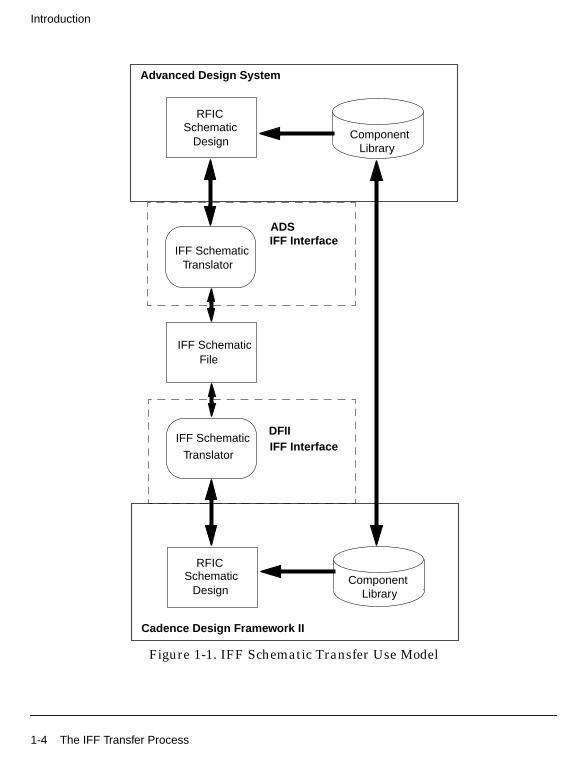
The IFF Transfer ProcessOnce the main requirements have been satisfied, your schematic can be transferredbetween Advanced Design System and Cadence DFII. Importing and exporting canbe initiated from either EDA design environment.
The diagram shown in Figure 1-1 describes the general use model for translating adesign using the IFF Interface as it applies to Advanced Design System and CadenceDFII. The link between the two EDA environments is established via the ADS andDFII IFF Interface. The two component libraries in both ADS and DFII must becompatible to support an IFF translation.
For more information on the library requirements, refer to Chapter 2, Before Usingthe IFF Translators.
Main Requirements 1-3
Introduction
Figure 1-1. IFF Schematic Transfer Use Model
SchematicRFIC
Design
IFF SchematicTranslator
IFF Interface
Advanced Design System
IFF SchematicFile
SchematicRFIC
Design
IFF Schematic
TranslatorIFF Interface
Cadence Design Framework II
ADS
DFII
ComponentLibrary
LibraryComponent
1-4 The IFF Transfer Process

What’s in this ManualThe goal of this manual is to help you get started, providing relevant examples thatteach you how to setup and use the software, and showing you where you can getmore information as you need it. This manual contains:
• Chapter 2, Before Using the IFF Translators describes how to configure yourCadence design environment to support IFF translation between ADS andDFII. This chapter also discusses some of the issues related to IFF schematictranslation in the ADS and DFII environments.
• Chapter 3, Importing IFF Schematic Files into ADS describes the procedure forimporting an IFF file into an Advanced Design System Schematic.
• Chapter 4, Exporting IFF Schematic Files from ADS describes the procedure forexporting an ADS Schematic to an IFF file from Advanced Design System.
• Chapter 5, Importing IFF Schematic Files into DFII describes the procedure forimporting an IFF file into DFII for use in Virtuoso Schematic Composer.
• Chapter 6, Exporting IFF Schematic Files from DFII describes the procedurefor exporting a Composer Schematic to an IFF file from DFII.
What’s in this Manual 1-5
Introduction
About Design TranslationIt is highly recommended that the IFF Translator be used only for schematictranslation in the presence of compatible component libraries in the twoenvironments that have been developed to support this translation process. The IFFTranslator can also be used to perform partial translation of a Cadence library intoan ADS library and vice versa. To complete the translation task however, asignificant amount of manual intervention is required.
This manual exclusively covers the schematic translation aspect of IFF translations.If you’re interested in translating a component library from Cadence to ADS or viceversa, Agilent Technologies Solution Services can provide you with specialized toolsand help. For more information, contact your Agilent Technologies salesrepresentative.
For information about Spectre netlist to ADS translation, see the Netlist Translatorfor SPICE and Spectre manual.
1-6 About Design Translation

Chapter 2: Before Using the IFF TranslatorsBefore using the IFF translators, there are several topics that must be addressed.This chapter is broken down into three main sections that cover these issues:
• “Configuring your Software for IFF Translation” on page 2-1
• “Understanding Component Library Requirements” on page 2-7
• “Constructing Schematics for IFF Translation” on page 2-9
After covering the information in this chapter, you’ll be ready to begin sharing yourschematic files between ADS and DFII using the IFF translators.
Configuring your Software for IFF TranslationThis section describes the details related to software requirements and configuringthe ADS and Cadence design environments to support IFF translation. Beforeattempting an IFF translation, the appropriate licenses must also be installed andthe Cadence environment must be configured to operate with the IFF translator.
Software Requirements
The IFF Translator described in this manual requires ADS 1.5 or later. IFF issupported by Cadence DFII versions 4.4.2*, 4.4.3QSR1, 4.4.5 and 4.4.6. IFF is alsosupported on all UNIX operating system versions from vendors which run thisCadence software. Refer to Table 2-1 for a summary of supported platforms. Foradditional information, please contact Cadence Design Systems, Inc.
* Sub-version 100.1 or later.
Table 2-1. Supported Platforms
CadenceDFIIVersion AIX4 HPUX10 HPUX11 SUN55 SUN56 SUN57
4.4.2* yes yes no yes yes no
4.4.3QSR1 yes yes yes yes yes yes
4.4.5 yes no yes yes yes yes
4.4.6 yes no yes yes yes yes
Configuring your Software for IFF Translation 2-1
Before Using the IFF Translators
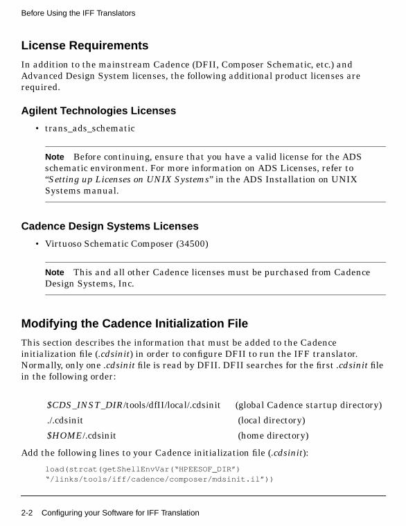
License Requirements
In addition to the mainstream Cadence (DFII, Composer Schematic, etc.) andAdvanced Design System licenses, the following additional product licenses arerequired.
Agilent Technologies Licenses
• trans_ads_schematic
Note Before continuing, ensure that you have a valid license for the ADSschematic environment. For more information on ADS Licenses, refer to“Setting up Licenses on UNIX Systems” in the ADS Installation on UNIXSystems manual.
Cadence Design Systems Licenses
• Virtuoso Schematic Composer (34500)
Note This and all other Cadence licenses must be purchased from CadenceDesign Systems, Inc.
Modifying the Cadence Initialization File
This section describes the information that must be added to the Cadenceinitialization file (.cdsinit) in order to configure DFII to run the IFF translator.Normally, only one .cdsinit file is read by DFII. DFII searches for the first .cdsinit filein the following order:
Add the following lines to your Cadence initialization file (.cdsinit):
load(strcat(getShellEnvVar(“HPEESOF_DIR”)“/links/tools/iff/cadence/composer/mdsinit.il”))
$CDS_INST_DIR/tools/dfII/local/.cdsinit (global Cadence startup directory)
./.cdsinit (local directory)
$HOME/.cdsinit (home directory)
2-2 Configuring your Software for IFF Translation

Adding the above information to your .cdsinit file loads the SKILL code that sets upthe IFF pull-down menu on the Cadence CIW as well as other code necessary forperforming IFF transfers between DFII and Advanced Design System.
Note SKILL is Cadence’s C/lisp-like interpretive programming language forframework and database integration.
Restarting Your Cadence Session
If you have already started your Cadence session and do not wish to interrupt it,source your .cdsinit file before attempting to use the IFF translator. For moreinformation on Cadence initialization files (.cdsinit), refer to your Cadencedocumentation under “Setting Cadence Environment Variables”. If you’re usingversion 4.4.5 or 4.4.6, you will need to restart your Cadence session to initiate thechange.
Setting up the System ‘.cdsenv’ File
A specific .cdsenv file must be created in the Cadence installation to support theoperation of the IFF translator. To perform this operation, a script is provided thatcopies the default .cdsenv file from the ADS installation to the Cadence installation.
To install the .cdsenv file:
1. Change to the $HPEESOF_DIR/links/tools/iff/cadence/composer directory.
2. Locate the script called setupCdsEnv. This script copies the default .cdsenv fileinto the Cadence root currently set in your path. The Cadence root isdetermined by using the cds_root command.
Note The cds_root command is located in the tools/bin directory of the Cadencedirectory hierarchy. You must have the tools/bin directory in your path for thesetupCdsEnv script to function properly.
3. Run the setupCdsEnv script. The .cdsenv file is copied to:
<cds_root>/tools/dfII/etc/tools/iff/.cdsenv
If the iff directory does not exist, it will be automatically created.
Configuring your Software for IFF Translation 2-3

Before Using the IFF Translators
Note If you do not have this environment file installed, you will get messagessimilar to the following:*WARNING* Cannot find /apps/cadence/4.4.3/tools.hppa/dfII/etc/tools/iffdirectory to load environment variables*WARNING* envGetVal: could not find tool[.partition] ‘iff’
About the Local ‘.cdsenv’ File
There is also a local .cdsenv file that is created and updated every time you clickApply or OK in the IFF Import and Export dialog boxes. This file contains the settingsof the various fields and check boxes and it can be found in the directory where youstarted the Cadence application. For example, if you change the scaling factor (see“Scaling Factor for Cadence to Target System” on page 6-8) from 200 to 250 and thenclick Apply , the setting is saved and will appear the next time you open either the IFFImport or Export dialog box. These settings can become system defaults by manuallyediting the system .cdsenv file, located in the <cds_root>/tools/dfII/etc/tools/iffdirectory, setting each of the variables in the .cdsenv file to the desired setting.
Verifying your Cadence IFF Configuration
After meeting your license requirements and modifying the Cadence initializationfile, you can run Cadence DFII to ensure that your configuration was successful. Tolaunch DFII and verify your setup:
1. In a terminal window, change to the appropriate directory.
2. Run DFII by typing the appropriate command (typically icms or icfb). TheCadence Command Interpreter Window (CIW) appears.
2-4 Configuring your Software for IFF Translation

Figure 2-1. Cadence CIW Window
3. Check that the IFF menu item is displayed in the CIW menu bar as shown inFigure 2-1. For detailed information on the available command options, refer toChapter 5, Importing IFF Schematic Files into DFII and Chapter 6, ExportingIFF Schematic Files from DFII.
Note Non-standard or customized start-up scripts for Cadence Design Framework IImay not be supported. If you have difficulties, contact your system administrator.
Configuring your Software for IFF Translation 2-5

Before Using the IFF Translators
Checking for the “basic” and “analogLib” Libraries
The basic library must be installed in Cadence DFII before attempting an IFFtranslation. If the basic library is not installed in the Cadence cdslib directory, thereare potential transfer issues related to pin mapping. Fundamentally, DFII will not beable to generate pins when translating an IFF schematic from ADS without havingthe basic library available in Cadence.
If the analogLib library is not installed in the Cadence cdslib directory, there arepotential transfer issues related to ground symbols and connector components. Ifyou’ve developed your own ground symbol and placed it in an existing library, ensurethat you activate the Export standard connectors as components option whenexporting an IFF schematic file from DFII to ADS. The Export standard connectors ascomponents option can be found in the Framework Output Transfer Form. For moreinformation on this option, refer to “Accessing the Framework Output Transfer Form”on page 6-2. Also ensure that you use your own connector components in ADS, asopposed to the standard ADS connectors (i.e. Port and Ground), to avoid any potentialproblems.
To ensure that the basic and analogLib libraries are available from the Cadence CIW:
1. Choose File > Open . The Open File dialog box appears.
2. In the Open File dialog box, click the Library Name pull-down menu item. If thebasic and analogLib libraries are installed, they should both be available in thismenu.
2-6 Configuring your Software for IFF Translation

3. If the basic and/or analogLib libraries are not installed, work with your systemadministrator to obtain a copy of the missing library or libraries.
Copy the basic library to:
<Cadence_install_dir>/tools/dfII/etc/cdslib/basic
Copy the analogLib library to:
<Cadence_install_dir>/tools/dfII/etc/cdslib/analogLib
4. Repeat steps 1 and 2 to verify that the libraries are now available from theOpen File dialog box.
Understanding Component Library RequirementsThe fundamental library requirement for a successful IFF transfer is that both theAdvanced Design System and Cadence Design Framework II contain compatiblecomponent libraries. This section provides an overview of compatible libraries anddiscusses the issues related to simulating your design.
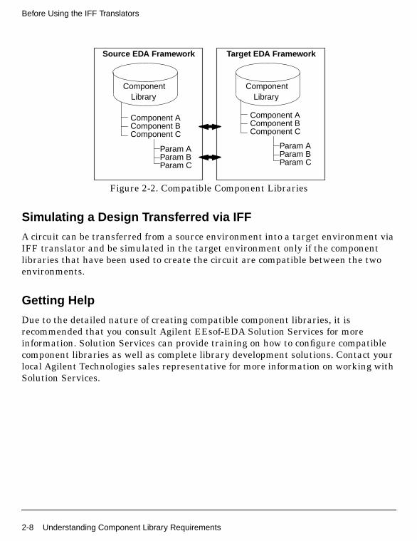
Compatible libraries between two design frameworks can be considered equivalentcomponent libraries for all practical purposes. While two EDA frameworks may havesome differences in the way component information is handled, the fundamentalcomponent parameters for each primitive component must map each other to havethe same function in one framework as it does in the other. Components andparameters such as component names, symbols, size and shape, symbol pin locations,etc. in the source framework must all map to corresponding components andparameters in the target framework. The diagram below displays an example of twoequivalent, or compatible component libraries within two separate EDA frameworks.
Understanding Component Library Requirements 2-7
Before Using the IFF Translators
Figure 2-2. Compatible Component Libraries
Simulating a Design Transferred via IFF
A circuit can be transferred from a source environment into a target environment viaIFF translator and be simulated in the target environment only if the componentlibraries that have been used to create the circuit are compatible between the twoenvironments.
Getting Help
Due to the detailed nature of creating compatible component libraries, it isrecommended that you consult Agilent EEsof-EDA Solution Services for moreinformation. Solution Services can provide training on how to configure compatiblecomponent libraries as well as complete library development solutions. Contact yourlocal Agilent Technologies sales representative for more information on working withSolution Services.
ComponentLibrary
ComponentLibrary
Source EDA Framework Target EDA Framework
Component AComponent BComponent C
Component AComponent BComponent C
Param AParam BParam C
Param AParam BParam C
2-8 Understanding Component Library Requirements

Constructing Schematics for IFF TranslationThe IFF schematic translator module enables bi-directional, fully hierarchicalschematic transfer between the ADS and Cadence DFII Frameworks. You can edityour schematic in either environment, and when you transfer edited material to theother environment, all edits are preserved, including property changes.
Before attempting to transfer a schematic via IFF, ensure that all componentlibraries are compatible in all frameworks. This step is essential for a successful IFFtransfer. For more information on compatible libraries, refer to “UnderstandingComponent Library Requirements” on page 2-7.
To have a successful IFF transfer, it is required that only components that arecontained within the compatible libraries be used in your designs. A hierarchicaldesign approach is recommended for the implementation of RFIC schematic designsin ADS.
Implementing Power Supply Connections
Power supply connections (power rails) should be implemented through portconstruction in the subcircuits or through global named connections.
Separating Simulation Control Elements
Simulation control elements are not transferred between ADS and DFII. Because ofthe different way the two environments handle simulation setup, it is recommendedthat your simulation control elements in Advanced Design System be separated fromyour circuit schematic information using a hierarchical approach (i.e. top levelcontains simulation control and instance(s) of subcircuits containing DUT). Thisenables you to transfer only the schematic information in the subcircuit and willrequire you to set up simulation controls independently in the Cadence environment.For more information, refer to “Creating Hierarchical Designs” in the ADS SchematicCapture and Layout manual.
Including Design Variables and Equations
If the design being transferred from ADS to DFII contains design variables orequations, the same variable should be manually set to the appropriate value orequation in the Cadence environment.
Constructing Schematics for IFF Translation 2-9

Before Using the IFF Translators
Note Advanced Design System equations are transferred in the IFF file; however,they are not translated to a Cadence equivalent.
Known Issues and LimitationsThere are several known issues or limitations that you should become familiar withbefore attempting to perform an IFF translation.
• Only one schematic is allowed per cell in Advanced Design System.
• Extracted views are not supported by the IFF translator.
• Parameterized subnetworks require special setup not is not covered in thismanual. It is recommended that parameterized subnetworks not be used if IFFis used to transfer designs between ADS and Cadence.
For information, see the Netlist Translator for SPICE and Spectre manual.
• Inherited Connections are not supported in IFF transfers in ADS version 1.5SP1A or earlier.
• Inherited Connections are supported in ADS via Power Pins. It is necessary tomanually place Power Pins on symbols in ADS. IFF library transfers will notset up pins that utilize the ADS version of Inherited Connections.
If IFF is used to transfer designs between ADS and Cadence, it is recommendedthat symbols use explicitly defined pins rather than Inherited Connections.
• ADS ports to have unique names. If multiple ports with the same name areused within a Cadence schematic, the IFF exporter will keep the first port withthe name. All subsequent ports with the common name will be converted towire labels.
• Area pins are not supported in ADS. It is important to have wires in yourCadence design connect to the center point of a symbol pin.
2-10 Known Issues and Limitations

• Design variable in Cadence are not transferred to ADS via IFF. It is necessaryto manually create a VAR component in ADS that will contain the CAdencedesign variables. Additionally, VAR components in ADS are not transferred toCAdence design variables. If VAR components are set up in ADS, you mustmanually create design variables in Cadence.
Known Issues and Limitations 2-11

Before Using the IFF Translators
2-12 Known Issues and Limitations

Chapter 3: Importing IFF Schematic Filesinto ADSThis chapter describes the procedure for importing an Intermediate File Format(IFF) schematic file into Advanced Design System.
Figure 3-1. IFF Schematic Import in ADS
The basic procedure for importing an IFF schematic file into ADS can be broken downinto several simple steps:
1. “Opening an ADS Project and Schematic Window” on page 3-2
2. “Accessing the Schematic Import dialog” on page 3-3
3. “Specifying the Import File Selection” on page 3-4
4. “Selecting Import IFF Options” on page 3-5
5. “Completing the IFF Import” on page 3-7
SchematicIFF SchematicIFF Schematic
Translator
Advanced Design System
IFF Interface
File
From DFIIIFF TranslatorADS
ComponentLibrary
3-1

Importing IFF Schematic Files into ADS
Opening an ADS Project and Schematic WindowOpen a project in ADS before attempting to import your design. Working in projectdirectories enables the translator to organize design files in the standard ADS filestructure. The import option will not be active in the File menu unless you open aproject. From the ADS Main window:
1. Choose File > New Project to open a new project or File > Open Project to open anexisting project.
For more information on working in project directories, refer to “ManagingProjects and Designs” in the Schematic Capture and Layout manual.
2. Before invoking the import procedure, close any open designs to remove anyactive designs from memory. In the ADS Main window, choose File > Close All .
3. Open a new ADS Schematic window by clicking the New Schematic Windowicon in the ADS Main window tool bar.
A new ADS untitled schematic window appears.
3-2 Opening an ADS Project and Schematic Window
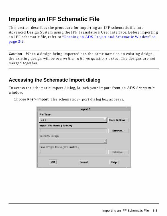
Importing an IFF Schematic FileThis section describes the procedure for importing an IFF schematic file intoAdvanced Design System using the IFF Translator’s User Interface. Before importingan IFF schematic file, refer to “Opening an ADS Project and Schematic Window” onpage 3-2.
Caution When a design being imported has the same name as an existing design,the existing design will be overwritten with no questions asked. The designs are notmerged together.
Accessing the Schematic Import dialog
To access the schematic import dialog, launch your import from an ADS Schematicwindow.
Choose File > Import . The schematic Import dialog box appears.
Importing an IFF Schematic File 3-3

Importing IFF Schematic Files into ADS
Specifying the Import File Selection
In the schematic Import dialog box, choose the type of file to import, specify thefilename, and supply other basic information needed by the translator.
1. In the Import dialog box, select IFF from the File Type drop-down list if it isn’talready displayed.
2. To specify the path and filename of the file you want to import, click Browse inthe Import dialog box. The Import File Selection dialog box appears.
3. Double-click as needed to locate the directory containing your IFF file in theDirectories field, then click the file in the Files field. Alternatively, you can enterthe full path and file name in the Selection field.
4. After selecting the design you want to import, click OK. You are returned to theImport dialog box and the selected filename appears in the field labeled ImportFile Name (Source).
5. Click More Options to define the import options. The Import IFF Options dialogbox appears.
3-4 Importing an IFF Schematic File

Selecting Import IFF Options
This section describes the choices available in the Import IFF Options dialog box.Import options for other file formats are detailed in the ADS “Importing andExporting Designs” manual.
To access the schematic Import IFF Options dialog box from the Import dialog, clickMore Options . The schematic Import IFF Options dialog box appears.
In the Import IFF Options dialog box, select the appropriate options for yourtranslation using the information below.
Remove IFF File After Import
Set the Remove IFF File After Import as desired. When selected, the .iff file isremoved once the IFF file is successfully imported. This option is deselected as thedefault, and the IFF file remains after import.
Log verbose messages
When the Log verbose messages option is selected, all translation information isrecorded in the ifftolib.log file resulting in step-by-step description of what happenedinternally during your translation. This option is primarily intended to be used as adiagnostics tool so the default mode for this option is deselected. Note that error andwarning messages will always appear in your status window regardless of thisselection.
Importing an IFF Schematic File 3-5

Importing IFF Schematic Files into ADS
Synchronize ports to symbol using node name
The Synchronize ports to symbol using node name option is not supported in the ADS1.5 or 2001 IFF importer. Ensure that this checkbox is deactivated.
Default Library Name For Library Parts
When the IFF file does not specify a library name for a component that needs to becreated, the library name specified in this field is used. This is only necessary forenvironments that do not support the concept of a library. Cadence will alwaysprovide a library name.
Note The Default Library Name For Library Parts field is identical to the field of thesame name in the Export IFF Options dialog box. Changes made to this field willmodify the contents of the field in the Export IFF Options dialog box. For moreinformation on Exporting IFF Schematic files, refer to Chapter 4, Exporting IFFSchematic Files from ADS.
About Component Libraries
A component library in Advanced Design System consists of a collection of componentdefinitions. Each primitive component has an associated component name, symboland predefined component parameters that include relevant physical and electricalcharacteristics.
The IFF translator can be used as the initial step in creating an ADS componentlibrary however; this topic is outside of the scope of this manual. Creating an ADScomponent library using IFF requires specialized tools and training. If you’reinterested in learning more about this topic, contact Agilent EEsof-EDA’s SolutionServices.
3-6 Importing an IFF Schematic File

Completing the IFF Import
After specifying the IFF import options, click OK in the Import IFF Options dialog boxto save your settings or Cancel to retain the default settings. After clicking OK, youare returned to the Import dialog box. Click OK to begin the translation.
When translation is complete, an Information Message dialog box appears stating,IFF Import Completed. The IFF Import log window also appears. Review the logmessage searching for any error messages or warnings generated during export.
Importing an IFF Schematic File 3-7

Importing IFF Schematic Files into ADS
3-8 Importing an IFF Schematic File

Chapter 4: Exporting IFF Schematic Filesfrom ADSThis chapter describes the procedure for exporting an Intermediate File Format (IFF)schematic from Advanced Design System.
Figure 4-1. IFF Schematic Export from ADS
The basic procedure for exporting an IFF file from ADS can be broken down intoseveral simple steps:
1. “Opening an ADS Project and Schematic Window” on page 3-2
2. “Accessing the Schematic Export dialog” on page 4-2
3. “Specifying the Export File Selection” on page 4-3
4. “Selecting Export IFF Options” on page 4-4
5. “Completing the IFF Export” on page 4-9
Schematic
Component
IFF SchematicIFF SchematicTranslator
Advanced Design System
IFF Interface
File
To DFIIIFF TranslatorADS
Library
4-1
Exporting IFF Schematic Files from ADS
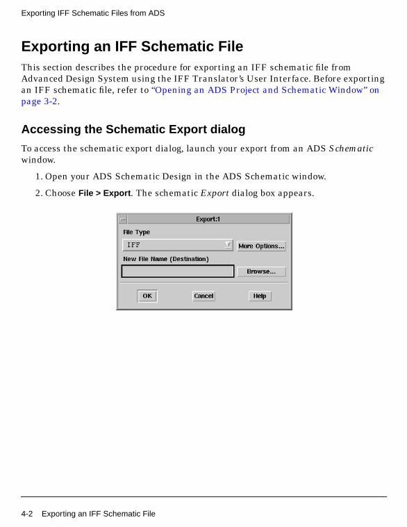
Exporting an IFF Schematic FileThis section describes the procedure for exporting an IFF schematic file fromAdvanced Design System using the IFF Translator’s User Interface. Before exportingan IFF schematic file, refer to “Opening an ADS Project and Schematic Window” onpage 3-2.
Accessing the Schematic Export dialog
To access the schematic export dialog, launch your export from an ADS Schematicwindow.
1. Open your ADS Schematic Design in the ADS Schematic window.
2. Choose File > Export . The schematic Export dialog box appears.
4-2 Exporting an IFF Schematic File

Specifying the Export File Selection
In the schematic Export dialog box, choose the type of file to export, specify the newfile name, and supply other basic information needed by the translator.
1. In the Export dialog box, select IFF from the File Type drop-down list if it isn’talready displayed.
2. To specify the path and filename of the file you want to import, click Browse inthe Export dialog box. The Export File Selection dialog box appears.
3. Double-click as needed to locate the directory for your exported IFF schematicfile in the Directories field then enter the new file name in the Selection field.Alternatively, you can enter the full path and file name in the Selection field.
4. After selecting the new location and name of your design, click OK. You arereturned to the Export dialog box and the selected path and file name appear inthe field labeled New File Name (Destination). When translated, the file name isautomatically appended with suffix .iff. Note that the .iff extension is onlyadded if the file name doesn’t already contain it.
5. Click More Options to define the export options. The Export IFF Options dialogbox appears.
Exporting an IFF Schematic File 4-3

Exporting IFF Schematic Files from ADS
Selecting Export IFF Options
This section describes the choices available in the schematic Export IFF Optionsdialog box.
To access the schematic Export IFF Options dialog box from the Export dialog, clickMore Options . The schematic Export IFF Options dialog box appears.
In the Export IFF Options dialog box, select the appropriate options for yourtranslation using the information below.
4-4 Exporting an IFF Schematic File

Destination IFF File name
Use this field to specify the full path and filename for the IFF file destination. To setthe directory path and filename:
1. Click Browse in the Export IFF Options dialog box. The Export File Selectiondialog box appears.
2. Double-click as needed to locate the directory to place your exported IFF file inthe Directories field. If a file that you want to overwrite already exists in thisdirectory, click the filename in the Files field. Alternatively, you can append thefile name to the directory path in the Selection field.
3. After selecting the destination for the design you want to export, click OK. Youare returned to the Export IFF Options dialog box and the selected path andfilename appears in the field labeled Destination IFF File name field.
IFF File Overwrite Options
Overwrite IFF File - When writing to an existing file, the contents of that file areoverwritten. While this is not the default setting, it is generally the preferred setting.
Exporting an IFF Schematic File 4-5

Exporting IFF Schematic Files from ADS
Append to IFF File - When writing to an existing file, the new file is appended to theexisting file. This is the default setting. The IFF file is not overwritten during theADS export by default. To transfer multiple designs, simply use the same filemultiple times. Each design is created in turn. This method enables you to transfer alimited amount of hierarchy when you don’t want to overwrite reference elements. Toimplement this method, set the hierarchy level to None, then export one sub-networkfollowed by the main design. No IFF data is generated for any of the referencedcomponents in either design, so the only two circuits overwritten during an importare the two designs transferred.
Output disabled instances to the IFF file
When this option is selected, if an instance is disabled in the schematic, it will still beoutput into the IFF file. If the checkbox is deselected (default), disabled instances willnot be exported. This option can be utilized to omit certain components from beingtransferred to remote environments that might not support the components (e.g.disable the simulation components prior to creating an IFF file to send to Cadence,which does not have any definitions for the simulator components). Activate thisoption if you want to get everything. Deactivate this option if you want to filter outthe unused/unwanted components.
Output ADS Item Definition properties
When this option is selected, ADS Item Definition properties are utilized to recreatethe information necessary to simulate a component for ADS. For example, if you haveparameters on a resistor, some Item Definition properties are created in the IFF file(e.g. R_ADS_UNIT=1), which allow the IFF importer to exactly recreate thecomponent as it exists in ADS. However, other tools will not recognize the ItemDefinition parameters, and may misinterpret the properties as being separate. Iflibrary symbols are being exported to other environments that do not recognize theADS Item Definition parameters, the option should be turned off. This option isdeselected by default.
Put a space between numbers and the scalar/unit
When this option is selected, parameter values are exported as they normally appearin ADS (i.e. with a space between the number and the scalar, e.g. “1 pF”). If thecheckbox is deactivated, the exporter converts the values into the IFF valuespecification, which is to have no space between a number and a scalar (e.g. "1pF").Ideally, an IFF exporter should interpret either form of number, and set the value
4-6 Exporting an IFF Schematic File
internally to whatever is normal for that environment. Some environments (e.g.Mentor Graphics) do not interpret the IFF property values in any way. For Mentor IC,this means the numbers need to have no space in them, because, when they are usedwithin SPICE simulations, the space will cause syntax errors in the simulator.However, for Mentor Board, they require the ADS components to have a space inthem, because the RF Architect ADS library is set up to expect values to have a spacebetween a number and a scalar/unit.
If you are exporting designs to Mentor Boardstation, you must select this option forIFF imports to work into their environment. An additional issue can come up if youcreate variables, and then assign scalar values to the variable (e.g. "R1 kOhms").When this is exported, if the option is not set, it would convert to "R1koh", whichcould no longer be interpreted correctly. Note that this second option is consideredbad practice (the scalar should be included in the variable value for R1, and no unitsshould be specified); however, ADS does allow you to format variables in this way. Ifyou are using variables in this way, you must set this option to true. This option isdeselected by default.
Default Library Name for Library Parts
When the IFF file does not specify a library name for a component that needs to becreated, the library name specified in this field is used. This is necessary forenvironments that do not support the concept of a library.
Design objects are stored in a group that uses the same name as the project directory,but library parts are stored in either the default library hpeesoflib or a library thatyou specify. The default library name can contain only alpha numeric characters.
Note The Default Library Name For Library Parts field is identical to the field of thesame name in the Import IFF Options dialog box. Changes made to this field willmodify the contents of the field in the Import IFF Options dialog box.
About Component Libraries
A component library in ADS consists of a collection of component definitions. Eachprimitive component has an associated component name, symbol and predefinedcomponent parameters that include relevant physical and electrical characteristics.
The IFF Translator can be used as the initial step in creating an ADS componentlibrary however, this topic is outside of the scope of this manual. Creating an ADScomponent library using IFF requires specialized tools and training. If you’re
Exporting an IFF Schematic File 4-7

Exporting IFF Schematic Files from ADS
interested in learning more about this topic, contact Agilent EEsof-EDA’s SolutionServices.
Schematic Hierarchy Option
The Schematic Hierarchy Option drop-down list enables you to establish how much ofthe schematic hierarchy is exported:
Current Design Only Write current level only. Complete design information for thecurrent design is exported. Instance-specific information (parameter values andcoordinates identifying position) is also exported. Detailed definitions of areferenced design are not exported.
Current Design, Selected Projects and No Library Parts Complete designinformation for the current design is exported. Referenced designs that reside in aproject selected for inclusion during export and are part of the current design’shierarchy are also exported. Library parts are not exported. This is the defaultsetting.
Current Design, Selected Projects and All Library Parts Complete designinformation for the current design is exported. Referenced designs that reside in aproject selected for inclusion during export and are part of the current design’shierarchy are also exported. In addition, library parts are exported.
Project Hierarchy
Displays the current project. If hierarchical, all included projects are listed in theappropriate order.
Projects Included During Schematic Export
This field contains the projects for which schematic design information is exported.You can customize this list if the current project is hierarchical.
To add a project to this list:
1. In the Project Hierarchy list, click the desired project.
2. Click the Include button. The project is added to the Projects Included list.
To include all projects, click Include All .
To remove a project from the Projects Included list:
1. In the Projects Included list, click the entry you want to remove.
4-8 Exporting an IFF Schematic File

2. Click the Remove button. The project is removed from the list.
To remove all entries from the Projects Included list, click Remove All .
This is an example of using the Project Hierarchy and Projects Included DuringSchematic Export fields. First you make a project called Proj_A that includes severaldesigns. Then you make another project called Proj_B and you want to reuse some ofthe designs from project Proj_A in project Proj_B. You can then include Proj_A inProj_B by using the Include button to have access to all the designs in Proj_A afteryour export is complete.
Completing the IFF Export
After specifying the IFF export options, click OK in the Export IFF Options dialog boxto save your settings or Cancel to retain the default settings. After clicking OK, youare returned to the Export dialog box. Click OK to begin the translation.
When translation is complete, an Information Message dialog box appears stating,IFF Export Completed. The IFF Export log window also appears. Review the logmessage searching for any error messages or warnings generated during export.
Exporting an IFF Schematic File 4-9

Exporting IFF Schematic Files from ADS
4-10 Exporting an IFF Schematic File

Chapter 5: Importing IFF Schematic Filesinto DFIIThis chapter describes the procedure for importing an Intermediate File Format(IFF) schematic file from the Cadence CIW.
Figure 5-1. IFF Schematic Import into DFII
Before attempting to import an IFF file into DFII, refer to Chapter 2, Before Usingthe IFF Translators. The basic procedure for importing an IFF schematic file intoDFII can be broken down into several simple steps:
1. “Accessing the Framework Input Transfer Form” on page 5-2
2. “Specifying the File Name and Setting Import Options” on page 5-3
3. “Completing the Import” on page 5-5
Cellview
Component
IFF SchematicIFF SchematicTranslator
Design Framework II
IFF Interface
File
From ADSIFF TranslatorCadence
Library
5-1

Importing IFF Schematic Files into DFII
Importing an IFF Schematic FileThis section describes the procedure for importing an IFF schematic file into theCadence DFII using the IFF Translator’s User Interface. Before importing an IFFschematic file, refer to the beginning of Chapter 5, Importing IFF Schematic Filesinto DFII.
The menu items described in this section are only available after the .cdsinit file hasbeen configured for an Intermediate File Format file transfer between DFII and ADS.For more information, refer to Chapter 2, Before Using the IFF Translators.
Accessing the Framework Input Transfer Form
To access the schematic import dialog, launch your import from the CadenceCommand Interpreter Window (CIW).
1. In a terminal window, change to the appropriate directory.
2. Run DFII by typing the appropriate command (typically icms or msfb). TheCadence Command Interpreter Window (CIW) appears.
Figure 5-2. Cadence CIW Window
5-2 Importing an IFF Schematic File

3. From the Cadence CIW, choose IFF > Import IFF . The Framework Input TransferForm appears.
Specifying the File Name and Setting Import Options
In the Framework Input Transfer Form, specify the file name, enter the names of anycomponents that you want ignored and supply other basic information needed by thetranslator.
Input File Name
In the Input File Name field, enter the full path and file name of the IFF filegenerated in Advanced Design System that you want to import into Cadence.
Do not place these instances in schematics
In the Do not place these instances in schematics field, enter the names of anycomponents that you want Cadence to ignore during the import. If the IFF filecontains symbol data for these components, the symbols are created, however; theyare not placed in the Cadence schematic. This option enables you to prevent theimport of ADS simulation and model components which do not have equivalentcomponents in DFII.
Importing an IFF Schematic File 5-3

Importing IFF Schematic Files into DFII
Do not overwrite existing symbols
Set the Do not overwrite existing symbols checkbox as desired. When this option isselected, existing symbols are preserved rather than overwritten. If a symbol does notexist prior to the transfer, it is created during the import. The default value isselected.
Do not change existing CDF for symbols
Set the Do not change existing CDF for symbols checkbox as desired. When thisoption is selected, Cadence cell Component Description Formats (CDFs) are notupdated during the import. The default value is selected.
Do not create user properties on symbols
When this option is selected, user instance properties are not created during theimport. The default value is selected and it is recommended to keep the defaultsetting when using ADS 1.3 and above to export the IFF file.
Map nodes named gnd
In the Map nodes named gnd to field, enter the ground node name mappinginformation. The default value is the gnd! used by Advanced Design System.
Map nodes named agnd
In the Map nodes named agnd to field, enter the analog ground node name mappinginformation. The default value is the agnd! used by Advanced Design System.
Callback Execution
There are three options available from the Callback Execution pull-down menu.
• All This option executes the evaluation of all functions or expressions used.
• Changed Parameters This option executes the evaluation of only thosefunctions or expressions that have changed.
• None This option disables any callback execution and is the default setting.
5-4 Importing an IFF Schematic File

Completing the Import
After you have completed the Framework Input Transfer Form, click Apply in theFramework Input Transfer Form to save your settings or Defaults to retain the defaultsettings. You can also click Cancel to abort the import operation. Click OK to begin thetranslation.
After the translation begins, all import log information is displayed in the CadenceCIW. One of the log lines will display what was created. Any warnings or errormessages encountered during the translation are also displayed in the log messages.
While cells are created in the appropriate Cadence libraries, the cell view is notautomatically displayed in the CIW. If full hierarchy was specified for the AdvancedDesign System export, existing schematics common to both program environmentsare overwritten on import. Symbols are overwritten only when you deselect the Donot overwrite existing symbols checkbox in the Framework Input Transfer Form. Ifyou have deselected this option, symbols only are overwritten; existing CDF data isnot overwritten. Only data needing to be overwritten is overwritten; and newversions are generated for all Cadence cell views.
Importing an IFF Schematic File 5-5

Importing IFF Schematic Files into DFII
5-6 Importing an IFF Schematic File

Chapter 6: Exporting IFF Schematic Filesfrom DFIIThis chapter describes the procedure for exporting an Intermediate File Format (IFF)schematic file from the Cadence CIW.
Figure 6-1. IFF Schematic Export from DFII
Before attempting to export an IFF file from DFII, refer to Chapter 2, Before Usingthe IFF Translators.
The basic procedure for exporting an IFF schematic file from DFII can be brokendown into several simple steps:
1. “Accessing the Framework Output Transfer Form” on page 6-2
2. “Specifying the File Name and Setting Export Options” on page 6-3
3. “Completing the Export” on page 6-6
Exporting an IFF Schematic FileThis section describes the procedure for exporting an IFF schematic file from DesignFramework II using the IFF Translator from the Cadence CIW. It is a recommendedpractice to export only design schematic information. This implies excludingeverything else from the export process such as simulation control blocks as well as
Cellview
Component
IFF SchematicIFF SchematicTranslator
Design Framework II
IFF Interface
File
To ADSIFF TranslatorCadence
Library
Exporting an IFF Schematic File 6-1

Exporting IFF Schematic Files from DFII
any other elements that do not map directly to Advanced Design System. Suchelements should exist at the top cell (symbol) view. To avoid complications, descendone level into this symbol view before beginning the export process.
The menu items described in this section are only available after the .cdsinit file hasbeen configured for an Intermediate File Format file transfer between DFII and ADS.For more information, refer to Chapter 2, Before Using the IFF Translators.
Accessing the Framework Output Transfer Form
To access the schematic export tools, launch your export from the Cadence CommandInterpreter Window (CIW).
1. In a terminal window, change to the appropriate directory.
2. Run Cadence by typing the appropriate command (typically icms or msfb). TheCadence Command Interpreter Window (CIW) appears.
Figure 6-2. Cadence CIW Window
3. From the Cadence CIW, choose IFF > Export IFF . The Framework OutputTransfer Form appears.
6-2 Exporting an IFF Schematic File
Specifying the File Name and Setting Export Options
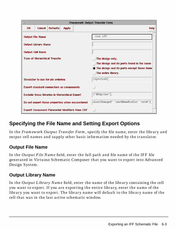
In the Framework Output Transfer Form, specify the file name, enter the library andoutput cell names and supply other basic information needed by the translator.
Output File Name
In the Output File Name field, enter the full path and file name of the IFF filegenerated in Virtuoso Schematic Composer that you want to export into AdvancedDesign System.
Output Library Name
In the Output Library Name field, enter the name of the library containing the cellyou want to export. If you are exporting the entire library, enter the name of thelibrary you want to export. The library name will default to the library name of thecell that was in the last active schematic window.
Exporting an IFF Schematic File 6-3

Exporting IFF Schematic Files from DFII
Output Cell Name
In the Output Cell Name field, enter the name of the Cadence cell that you wantCadence to export. The cell name will default to the cell name of the cell that was inthe last active schematic window.
Type of Hierarchical Transfer
There are four choices available from the Type of Hierarchical Transfer section of theFramework Output Transfer Form. For design exports, it is recommended that thesecond button is selected so that the output IFF file contains only hierarchical blocksof the design and none of the library parts. For detailed information on each of theselections, refer to the descriptions below.
The design Only When this option is selected, only the schematic and symbolicviews of the top-level design are exported. No hierarchy is translated. For thisoption to function properly, all of the instances used in the design must havelibrary elements that already exist in one of the libraries available in ADS.
The design and its parts found in the same library When this option is selected, theschematic and symbolic views of the open design are exported. Additionally, allschematic and symbolic views of cells (included in the cell) in the same library asthe open design are output into the IFF file. Any instance of reference library cells(that is, cells from a library other than that of the open design) are not exported.For this option to function properly, all of the cells placed from other libraries mustalready exist in one of the libraries available in ADS.
The design and its parts except those found in HP_excludeLibs When this option isselected, the schematic and symbolic views of the open design are exported.Additionally, the schematic and symbolic views of any instance encountered in thedesign are exported unless the instance belongs to a library appearing in theHP_excludeLibs list. For this option to function properly, any cell placed from alibrary listed in HP_excludeLibs must already exist in one of the librariesavailable in ADS.
Caution The design and its parts except those found in HP_excludeLibs is thedefault setting for this form. Exporting with this option set may causesimulation problems in Advanced Design System and should be avoided. Thissetting is typically used for establishing a reference library in ADS.
6-4 Exporting an IFF Schematic File

The entire library When this option is selected, the schematic and symbolic viewsof the open design are exported. The schematic and symbolic views of all otherdesigns in the library are also exported, whether the cells have been placed in theopen design or not. Nothing from any other library is exported.
This option is provided so that reference libraries from Cadence can be moved intoAdvanced Design System. After the file has been exported, it will still be necessaryto perform simulation setups on all components. The steps required to build afunctional ADS version of any Cadence reference library is complex and currentlyundocumented as discussed in “Understanding Component LibraryRequirements” on page 2-7. For information on creating compatible componentlibraries for use with IFF, refer to “Getting Help” on page 2-8.
Simulator to use for pin ordering
The Simulator to use for pin ordering field is used to designate the simulator to usefor component pin ordering. Enter (spectreS) since ADS models are typicallytranslated from Spectre subcircuit models. The default value is (spectreS).
Export standard connectors as components.
The IFF translator normally converts ports and grounds to an Advanced DesignSystem equivalent. When this option is selected, ports and grounds are nottranslated to ADS equivalents. This requires that the Cadence port or ground betransferred as a library component. When the Export standard connectors ascomponents option is selected, all standard connectors are translated as componentsin ADS. The default setting for this option is deselected.
Exclude these libraries in Hierarchical Export
Components listed in the Exclude these libraries in Hierarchical Export field are nothierarchically exported. Thus, no symbol or schematic information is created forthese components. Instance data is still generated.
Do not export these properties when encountered
The properties listed in the Do not export these properties when encountered field arenot included in symbols or instance records. This option is useful for suppressingCadence system properties.
Exporting an IFF Schematic File 6-5

Exporting IFF Schematic Files from DFII
Export Component Parameter Modifiers from CDF
When the Export Component Parameter Modifiers from CDF option is selected,component parameter modifiers contained in the Cadence Component DescriptionFormat (CDF) are exported to Advanced Design System. The default setting for thisoption is deselected.
Completing the Export
After you have completed the Framework Output Transfer Form, click Apply in theFramework Output Transfer Form to save your settings or Defaults to retain thedefault settings. You can also click Cancel to abort the export operation. Click OK tobegin the translation.
After the translation begins, all export log information is displayed in the CadenceCommand Interpreter Window (CIW). One of the log lines will display what wascreated. Any warnings or error messages encountered during the translation are alsodisplayed in the log messages.
Additional Export OptionsThis section describes some of the additional options available from the Cadence CIWIFF command menu.
Export library data for formsets
This section describes the selections available from the Export library data forformsets dialog box. When the menu command IFF > Export cyclic data for formsets isselected from the Cadence CIW, the Export library data for formsets dialog boxappears.
6-6 Additional Export Options

Note This dialog box was created exclusively for library customizing and should notbe used without consulting Agilent Technologies Solution Services. For moreinformation, contact your Agilent Technologies sales representative.
Data File Name
The data file is a Cadence file that can be utilized by the Library Translator, a customtool available from Agilent Technologies Solution Services. The file name entered intothis field contains information about all of the cyclic fields for a given library. Do notenter a file extension when entering the file name as two separate files are createdduring the export. One will have a .dat extension, which is a semi-binaryrepresentation of the cyclic fields, which will be used in the Library Translator sothat a you can choose what formset a Cadence parameter will utilize. The second filewill have a .ael extension that will contain the ADS Application Extension Language(AEL) code necessary to create the needed forms and formsets for the ADSenvironment.
Library Name
This field is used to enter the name of the library that you want to export cyclic fielddata from.
Prefix all form names with
In some cases, it may be necessary to prefix the form names with the library name orthe library and cell name. This field enables you to designate a prefix in order togenerate unique form and formset names.
As an example, if you were exporting data from the analogLib and generic_foundrylibraries, both of these libraries contain a cell named npn that has a parameter calledregion. In analogLib, the values are on and off. In generic_foundry, the values are on,off and reverse. When the formsets are generated, if the formset name is npn_region,the analogLib and genericLib components could not be used simultaneously in ADSas formsets would overlap. It is necessary to prefix the formset names so that theywill be unique. This is done by specifying analogLib as the prefix when exporting theanalogLib library, and specifying generic_foundry when exporting thegeneric_foundry library. Now, the formset name for analogLib would beanalogLib_npn_region, and the formset name for generic_foundry would begeneric_foundry_npn_region.
Additional Export Options 6-7

Exporting IFF Schematic Files from DFII
Configure IFF Variables
This section describes the selections available from the Configure IFF Variablesdialog box. When the menu command IFF > Configure IFF Variables is selected fromthe Cadence CIW, the Configure IFF Variables dialog box appears.
Scaling Factor for Cadence to Target System
When transferring cells from Cadence to Advanced Design System, the Cadencesymbol sizes tend to be about one half the size of ADS symbol sizes. This results inpoor quality schematic resolution. This scaling factor can be used during an export toimprove the resolution by using the default value (200) to make all Cadence symbolsand schematics twice the size in ADS. Additionally, during an import, all values arereduced to 50% of their original size.
Exclude these libraries in Hierarchical Export
This field enables you to specify a set of libraries that should not have symbols andschematics included in hierarchical exports. The primary purpose of excludinglibraries is that when a reference library is used in Cadence, a duplicate of thatlibrary must be created in ADS. The duplicate library contains all of the simulationsetup data that is not contained within the Cadence library. If the components fromthe reference library are output into the IFF file, new components without thenecessary simulation setups are created in ADS and the design will not simulate.
As an example, lets say that you have a design in a library mylib called myschematic.Within this design, you place an instance of the cell res from the analogLib library. Ifyou specify analogLib in the Exclude these libraries in Hierarchical Export field, andthen proceed to perform a full hierarchical export, the symbol for mylib myschematicis exported and the schematic mylib myschematic is created in the IFF file. However,the symbol for analogLib is not placed in the IFF file because it has been designated
6-8 Additional Export Options

as being excluded. If analogLib is not specified in the exclude library list, the symbolfor analogLib res is created in the IFF file. Note that if analogLib res is created as asymbol, it is up to you to create the proper simulation setup for the component whenit is imported into ADS.
Note This field matches the field found on the IFF export dialog.
Do not export these properties when encountered
This field is provided primarily so that Cadence system properties can be omittedfrom the IFF export if desired. It’s main purpose is to avoid clutter in the propertyfields of instances. You can decide if you want to omit properties that are notnecessarily Cadence system properties, or whether you want to have the propertiestranslated.
Export standard connectors as components
This checkbox enables you to specify how to translate connectors. A connector in thiscontext is defined as a pin or a ground component. In Cadence, this means basic ipin,basic opin, basic iopin, analogLib gnd, analogLib gnda, and analogLib gndd. Whenany of these components are encountered, and this checkbox is deactivated, thecomponents are converted into the ADS equivalent components (either Port for thebasic pins or Ground for the analogLib ground component). Because the ADScomponents are shaped differently from the Cadence components, it may be moredesirable to transfer the components without converting them into ADS equivalentsensuring that the schematic will look identical to its Cadence representation.Activate this checkbox if you want to translate your connectors as Cadencecomponents.
Note The analogLib Design Kit for ADS contains all of these components and theyare already setup to function properly as the default ADS connectors. If you want toactivate this checkbox, it is recommended that the factory generated analogLibDesign Kit be used in the ADS environment.
Additional Export Options 6-9

Exporting IFF Schematic Files from DFII
Framework Software VersionThis section describes the Framework Software Version dialog box. When the menucommand IFF > About is selected from the Cadence CIW, the Framework SoftwareVersion dialog box appears.
This dialog box displays:
• The IFF for Cadence version number.
• The Agilent Technologies Copyright information.
• Revision information for the init.il, cdsin.il and cdsout.il files.
• Information on where to obtain the latest version of the mdsinit.il file.
Use this information when contacting Agilent Technologies for technical support.
6-10 Framework Software Version

Index
AADS, 1-1Application Extension Language, 6-7Item Definition properties, 4-6projects, 3-2schematic, 3-2, 4-2
analogLib, 6-7, 6-8Design Kit, 6-9gnd, gnda & gndd, 6-9library, 2-6
Bbasic
ipin, opin & iopin, 6-9library, 2-6
CCadence
Cadence Design Systems, 2-1, 2-2CDF, 6-6cell view, 6-4CIW, 2-3, 2-4, 5-2, 6-2components, 6-9customized start-up scripts, 2-5data file, 6-7environment variables, 2-3initialization file, 2-2restarting your session, 2-3running DFII, 2-4symbols, 6-8system properties, 6-5, 6-9Virtuoso Schematic Composer, 2-2
cell name, 6-4, 6-7command interpreter window, 2-3, 2-4, 5-2,
6-2component libraries, 1-3, 1-6
translation, 1-6components
Cadence, 6-9component description format, 6-6connector components, 2-6mapping, 2-7parameter modifiers, 6-6parameters, 2-7pin ordering, 6-5
translating, 4-6connectors, 6-5, 6-9coordinates, 4-8cyclic field data, 6-7
Ddata file, 6-7Design Kits
analogLib, 6-9designs
design objects, 4-7design variables, 2-9identical names, 3-3referenced designs, 4-8transferring multiple designs, 4-6
DFII, 1-1, 1-2non-standard start-up scripts, 2-5supported versions, 2-1
diagnostics, 3-5directories
cdslib, 2-6
EEDA, 1-1environment variables
Cadence, 2-3equations, 2-9error messages, 3-5, 6-6export log, 6-6exporting schematics, 4-1, 6-1extracted views, 2-10
Ffiles
.ael extension, 6-7
.cdsinit, 5-2, 6-2
.dat extension, 6-7cdsinit, 2-2cdsout.il, 6-10data file, 6-7file destination, 4-5file extension, 6-7file selection, 3-4, 4-3init.il, 6-10mdsinit.il, 6-10
form names, 6-7
Index-1

formsets, 6-7Framework
Input Transfer Form, 5-3Output Transfer Form, 2-6, 6-3Software Version, 6-10
Ggeneric_foundry, 6-7genericLib, 6-7global named connections, 2-9ground symbols, 2-6grounds, 6-5, 6-9
Hhierarchical
designs, 2-9, 6-4exports, 6-8projects, 4-8
HP_excludeLibs, 6-4hpeesoflib, 4-7
IIC design, 1-3icfb, 2-4icms, 2-4, 5-2, 6-2IFF, 1-1
export options, 4-4import options, 3-5pull-down menu, 2-3, 2-5translation availability, 1-3translators, 1-2, 2-1use model, 1-4
ifftolib.log, 3-5importing
schematics, 3-1, 5-1instance data, 6-5instance records, 6-5
Llibraries, 6-8
analogLib, 2-6, 6-7, 6-8basic, 2-6compatible component libraries, 1-6, 2-7component library requirements, 2-7, 3-6default library name, 4-7generic_foundry, 6-7library cells, 6-4library customization, 6-7
library development, 2-8library name, 3-6, 4-7, 6-3, 6-7missing libraries, 2-7
Library Translator, 6-7licenses, 2-1, 2-2log messages, 6-6
Mmissing libraries, 2-7msfb, 5-2, 6-2
Nnpn, 6-7npn_region, 6-7
Ooperating system versions, 2-1
Pparameter
spacing, 4-6values, 4-8
partial translation, 1-6pins, 6-9
pin mapping, 2-6pin ordering, 6-5
ports, 6-5port construction, 2-9
power rails, 2-9projects
ADS, 3-2hierarchical, 4-8
property fields, 6-9
Rregion, 6-7
Sscaling factor, 6-8schematic, 6-5
ADS, 3-2, 4-2export, 6-1hierarchy, 4-8import, 3-1, 5-1resolution, 6-8schematics per cell, 2-10translation, 1-6, 2-9view, 6-5
Index-2

simulation, 2-8, 6-8control elements, 2-9
SKILL, 2-3specialized tools, 1-6spectre, 6-5subcircuits, 2-9symbol, 6-5
sizes, 6-8view, 6-4, 6-5
system properties, 6-9
Tthird party frameworks, 1-3translation
schematic, 2-9
Uunique form and formset names, 6-7
Vversions
Cadence version number, 6-10cdsin.ilfiles
cdsin.il, 6-10cdsout.il, 6-10init.il, 6-10mdsinit.il, 6-10
Virtuoso Schematic Composer, 1-1, 2-2, 6-3
Wwarning messages, 3-5, 6-6
Index-3

Index-4