rfic dynamic link library guideliterature.cdn.keysight.com/litweb/pdf/ads15/pdf/dynlnklc.pdf ·...
TRANSCRIPT

Advanced Design System 1.5
RFIC Dynamic Link Library Guide
March 2001

Notice
The information contained in this document is subject to change without notice.
Agilent Technologies makes no warranty of any kind with regard to this material,including, but not limited to, the implied warranties of merchantability and fitnessfor a particular purpose. Agilent Technologies shall not be liable for errors containedherein or for incidental or consequential damages in connection with the furnishing,performance, or use of this material.
Warranty
A copy of the specific warranty terms that apply to this software product is availableupon request from your Agilent Technologies representative.
Restricted Rights Legend
Use, duplication or disclosure by the U. S. Government is subject to restrictions as setforth in subparagraph (c) (1) (ii) of the Rights in Technical Data and ComputerSoftware clause at DFARS 252.227-7013 for DoD agencies, and subparagraphs (c) (1)and (c) (2) of the Commercial Computer Software Restricted Rights clause at FAR52.227-19 for other agencies.
Agilent Technologies395 Page Mill RoadPalo Alto, CA 94304 U.S.A.
Copyright © 2001, Agilent Technologies. All Rights Reserved.
Acknowledgments
Cadence® and Analog Artist® are registered trademarks of Cadence Design SystemsIncorporated.Design Framework II™ and Composer™ are trademarks of Cadence Design SystemsIncorporated.Copyright © 1997 Cadence Design Systems Incorporated. All rights reserved.
ii
Contents1 Introduction
Using Examples........................................................................................................ 1-2Intended Audience.................................................................................................... 1-2
2 Getting ADS Device Parameter InformationListing Available Devices .......................................................................................... 2-1Getting Device Parameters....................................................................................... 2-1
Viewing Device Output ....................................................................................... 2-2
3 Creating the Netlist InterfaceCreating the ads Symbol View for a Component...................................................... 3-1Modifying the Component Description Format ......................................................... 3-4
Getting Existing CDF Information for a Component ........................................... 3-5Editing the CDF File ........................................................................................... 3-5Using the CDF Editor ......................................................................................... 3-6Loading the Modified CDF File ........................................................................... 3-16
Modifying the Component Netlisting Function(s)...................................................... 3-16
4 Creating Model FilesCreating a Simple ADS Model File ........................................................................... 4-1Creating a Parametric Subnetwork Model File ......................................................... 4-2Defining Instance Parameters using Expressions .................................................... 4-2Defining Model Parameters using Expressions ........................................................ 4-3
A References
B Adding CDF/SimInfo to a Component LibraryUsing cdfDumpAll ..................................................................................................... B-1
Dumping the CDF for an Entire Component Library........................................... B-1Dumping the CDF for Individual Components .................................................... B-1
Using the Edit Component CDF Form...................................................................... B-2
C Modifying the basic Library
D Modifying the analogLib LibraryUsing almBuildLibrary in a UNIX Shell Script ........................................................... D-2
E ADS Simulator Input SyntaxHardware and Operating System Requirements...................................................... E-1Setting Environment Variables.................................................................................. E-1Using the hpeesofsim Command ............................................................................. E-2Interpreting this Appendix......................................................................................... E-3Codewording and Security ....................................................................................... E-5General Syntax......................................................................................................... E-5
iii

The ADS Simulator Syntax....................................................................................... E-6Field Separators ................................................................................................. E-6Continuation Characters..................................................................................... E-6Name Fields ....................................................................................................... E-6Parameter Fields ................................................................................................ E-7Node Names ...................................................................................................... E-7Lower/Upper Case.............................................................................................. E-7Units and Scale Factors ..................................................................................... E-7Booleans ............................................................................................................ E-10Ground Nodes .................................................................................................... E-10Global Nodes...................................................................................................... E-11Comments .......................................................................................................... E-11Statement Order................................................................................................. E-11Naming Conventions .......................................................................................... E-11Currents.............................................................................................................. E-12
Instance Statements................................................................................................. E-13Model Statements..................................................................................................... E-13Subcircuit Definitions ................................................................................................ E-14Expression Capability ............................................................................................... E-16
Constants ........................................................................................................... E-16Variables............................................................................................................. E-17Expressions........................................................................................................ E-19Functions............................................................................................................ E-19Conditional Expressions..................................................................................... E-35
VarEqn Data Types................................................................................................... E-37Type conversion.................................................................................................. E-38
‘‘C-Preprocessor’’...................................................................................................... E-38File Inclusion ...................................................................................................... E-38Library Inclusion ................................................................................................. E-39Macro Definitions................................................................................................ E-39Conditional Inclusion .......................................................................................... E-40
Data Access Component.......................................................................................... E-41Reserved Words....................................................................................................... E-43
Index
iv

Chapter 1: IntroductionThe RFIC Dynamic Link for Cadence enables you to simulate your Cadence designsin the Advanced Design System (ADS) environment. Designs entered in the CadenceSchematic and stored in the Cadence design database are represented on the ADSschematic via its symbol view. The circuits can be simulated together with arbitrarycombinations of ADS system and circuit components using all the circuit simulatorsavailable in ADS.
The Dynamic Link requires an extension of the process library to support thenetlister and also requires the development of model files in ADS format. Thisadditional information is used to generate netlists in ADS format as shown inFigure 1-1.
Figure 1-1. Simulation Data Flow with the RFIC Dynamic Link
Note If you are planning to use components from the basic and analogLib librariesin your designs, refer to Appendix C, Modifying the basic Library and Appendix D,Modifying the analogLib Library for additional information.
This document provides information on how to make these additions, articulated intothe following two categories:
• Creating the Netlist Interface: This task consists of modifying the Cadencelibrary database by adding ADS simulation information to the Component
ADSSimulatorNetlister
ADSModelFiles
CadenceCDF
1-1

Introduction
Description Format (CDF) and creating an ADS Cellview for each librarycomponent.
• Creating Model Files: This is done by creating ASCII text files, formatted forADS, that contain model parameters for each of the components.
Using ExamplesEach of the above tasks is described with examples. The Dynamic Link includes amodified version of the analogLib library installed under$IDF_INSTALL_DIR/cdslib/4/4/* which is used in the examples. If you do nothave write access to this directory or do not want to overwrite it, make a copy of thedirectory first as follows:
cd $IDF_INSTALL_DIR/cdslib/4.4.*
find analogLib -depth -print | cpio -pd < mydir>
If you make a copy of the library (recommended), ensure that you edit your cds.lib fileto point to your own copy of analogLib instead of to the original installed version.
Intended AudienceThe information contained in this manual applies to EDA engineers and managersresponsible for creating and maintaining process libraries who:
• would like to implement a design flow based on the integration of ADS andCadence DFII using the RFIC Dynamic Link.
• have an existing Cadence component library which supports at least onecommercially available SPICE simulator.
• are familiar with the Cadence library structure and Component DescriptionFormat (CDF).
If you are familiar with the topics above, you can successfully complete the librarymodification using the information contained in this manual.
The following rules apply to this guide
• Wherever a shell variable is set, the Korn shell syntax is presented; for C shellsyntax, change export to setenv and remove the equal sign (=).
• Unless otherwise mentioned, assume case sensitivity.
1-2 Using Examples

• If you don’t understand a particular term or acronym, refer to the “Glossary” inthe RFIC Dynamic Link User’s Guide.
• For information on the ADS Cadence Menu and the Cadence AtrtistUtilitiesmenu, refer to the “Command Reference” in Appendix A of the RFIC DynamicLink User’s Guide.
Intended Audience 1-3

Introduction
1-4 Intended Audience

Chapter 2: Getting ADS Device ParameterInformationThis chapter describes how to obtain parameter information for devices supported byAdvanced Design System (ADS). The parameter information is needed to completethe tasks outlined in subsequent chapters.
The ADS Simulator provides helpful information on netlist and model formatting viaa terminal window. To use the ADS Simulator for this purpose, ensure that yourenvironment has been configured for use with Dynamic Link. For more informationon setting up your environment, refer to “Administrative Tasks” in the RFIC DynamicLink User’s Guide.
Listing Available DevicesThis section describes how to use the hpeesofsim command to list available devices.
In a terminal window, enter:
hpeesofsim -help
A list of Available devices and analyses are displayed.
Getting Device ParametersThis section describes how to use the hpeesofsim command to obtain parameterinformation for a specified device. From a terminal window, enter:
hpeesofsim -help <device_name>
where <device_name> is derived using the procedure described above in ListingAvailable Devices.
Note All device names are case sensitive. Use the hpeesofsim -help command toverify the correct case and spelling.
Listing Available Devices 2-1

Getting ADS Device Parameter Information
Viewing Device Output
The output of the ADS Simulator help for a specific device is a generated list ofinstance and model information. The output can be divided into four parts; theInstance Statement, the List of Instance Parameters, the Model Statement and theList of Model Parameters.
The examples below show the simulator output for a Bipolar Junction Transistor(BJT). To view the entire list of device parameters in a terminal window, enter:
hpeesofsim -help BJT
1. Instance Statement - The first section of the output produces the netlistinstance statement format for the device.
Netlist instance statement format:
ModelName [:Name] collector base emitter ... <parameter=value> ... ; (device)
For more information, refer to “Instance Statements” on page -13 in AppendixE.
2. List of Instance Parameters - The second section contains the list of instanceparameters that can be netlisted in the instance statement.
List of available instance parameters:
Parameters: Area smorr Junction area factor. Region s---i DC operating region, 0=off, 1=on, 2=rev, 3=sat. Temp (C) smorr Device operating temperature. Gbe (Siemens) ---rr Small Signal Base Emitter Conductance. Cbe (F) ---rr Small Signal Base Emitter Capacitance. Gb (Siemens) ---rr Small Signal External Base Conductance. Cbc (F) ---rr Small Signal Internal Base Collector Capacitance. Cbcx (F) ---rr Small Signal External Base Collector Capacitance. Ccs (F) ---rr Small Signal Collector to Substrate Capacitance. dQbe_dVbc (F) ---rr Small Signal Vbc To Qbe Transcapacitance. dIce_dVbe (Siemens) ---rr Small Signal Forward Transconductance gm. dIce_dVbc (Siemens) ---rr Small Signal Reverse Transconductance gmr. dIbe_dVbc (Siemens) ---rr Small Signal Reverse Transconductance gmr. dIbx_dVbe (Siemens) ---rr External Base Transconductance dIbx_dVbe. dIbx_dVbc (Siemens) ---rr External Base Transconductance dIbx_dVbc. NPN s---b NPN bipolar transistor. PNP s---b PNP bipolar transistor. Mode s---i Nonlinear spectral model on/off. Noise s---b Noise generation on/off.
2-2 Getting Device Parameters

Example of an instance statement containing some instance parameters:
NPN:Q1 c b e s Area=10 Region=1
3. Model Statement - The third section contains the device model statementformat:
model ModelName BJT <parameter=value> ...
For more information, refer to “Model Statements” on page -13 in Appendix E.
4. List of Model Parameters - The last section contains the model parameterinformation used to build the ASCII model file.
Note The use of ellipse (…) in the following output format indicates that someof the information has not been shown for conciseness.
List of available model parameters:
model Parameters: NPN s---b NPN bipolar transistor. PNP s---b PNP bipolar transistor. Is (A) smorr Saturation current. Js (A) smorr Saturation current. Bf smorr Forward beta. Nf smorr Forward emission coefficient. Vaf (V) smorr Forward Early voltage. Vbf (V) smorr Forward Early voltage. ... wBvbe (V) s--rr Base-emitter reverse breakdown voltage (warning).
wBvbc (V) s--rr Base-collector reverse breakdown voltage (warning). wVbcfwd (V) s--rr Base-collector forward bias (warning). wIbmax (A) s--rr Maximum base current (warning). wIcmax (A) s--rr Maximum collector current (warning). wPmax (W) s--rr Maximum power dissipation (warning). Approxqb s---b use the approximation for Qb vs Early voltage. Lateral s---b Lateral substrate geometry. Null s---- Has no effect.
Example of Model Statement containing some model parameters (note the use ofthe backslash (\) character):
model npn BJT NPN=yes Is=4.598E-16 Bf=175 Nf=0.9904 Vaf=22 Ikf=0.8 \ Ise=1.548E-14 Ne=1.703 Br=76.1 Nr=0.9952 Var=2.1 \ Ikr=0.02059 Isc=3.395E-16 Nc=1.13 Rb=8 Irb=8E-05 \ Rbm=3 Re=0.45 Rc=6 Xtb=0 Eg=1.11 Xti=3 Cje=8.7E-13 \ Vje=0.905 Mje=0.389 Cjc=3.6E-13 Vjc=0.4907 Mjc=0.2198 \
Getting Device Parameters 2-3

Getting ADS Device Parameter Information
Xcjc=0.43 Tf=1e-11 Xtf=50 Vtf=test(AAA) Itf=0.32 Ptf=32 \ Tr=1E-09 Fc=0.6
In the previous definition, the parameter attributes have the followinginterpretation:
For more information on parameter attributes, refer to Table 2-1.
field 1: settable
s = settableS = settable and required
field 2: modifiable
m = modifiable
field 3: optimizable
o = optimizable
field 4: readable
r = readable
field 5: type
b = booleani = integerr = real numberc = complex numberd = device instances = character string
2-4 Getting Device Parameters

Table 2-1. Model Parameter Attribute Definitions
Attribute Meaning Example
settable Can be defined in the instance ormodel statement. Most parametersare settable, there are a few caseswhere a parameter is calculatedinternally and could be used either inan equation or sent to the dataset viathe OutVar parameter on thesimulation component. Theparameter must have its full address.
Gbe (Small signal Base-EmitterConductance) in the BJT model canbe sent to the dataset by settingOutVar=”MySubCkt.X1.Gbe” onthe simulation component.
required Has no default value; must be set tosome value, otherwise the simulatorwill return an error.
modifiable The parameter value can be swept insimulation.
optimizable The parameter value can beoptimized.
readable Can be queried for value in simulationusing the OutVar parameter. Seesettable.
boolean Valid values are 1, 0, True, and False.
integer The maximum value allowed for aninteger type is 32767, values between32767 and 2147483646 are still valid,but will be netlisted as real numbers.In some cases the value of aparameter is restricted to a certainnumber of legal values.
The Region parameter in the BJTmodel is defined as integer but theonly valid values are 0, 1, 2, and 3.
real number The maximum value allowed is1.79769313486231e308+.
complex number The maximum value allowed for thereal and imaginary parts is1.79769313486231e308+.
Getting Device Parameters 2-5

Getting ADS Device Parameter Information
device instance The parameter value must be set tothe name of one of the instancespresent in the circuit.
The mutual inductance component(Mutual), where the parametersInductor1 and Inductor2 are definedby instance names of inductorspresent in the circuit or by a variablepointing to the instance names.Inductor1=”L1” or Inductor1=Xyzwhere Xyz=”L1”
character string Used typically for file names. Must bein double quotes.
Filename=”MyFileName”
Table 2-1. Model Parameter Attribute Definitions
Attribute Meaning Example
2-6 Getting Device Parameters
Chapter 3: Creating the Netlist InterfaceThis chapter describes how to modify the Cadence library database. This includescreating a new ads symbol view for each library component as well as adding an ADSsimulation information section to the Component Description Format (CDF). Thisprocedure can be divided into the following tasks:
• Creating the ads Symbol View for a component
• Modifying the CDF for a component
• Getting existing CDF information for a component
• Editing the CDF File contents
• Loading the modified CDF file
• Modifying the component netlisting function(s)
Note While the procedure for modifying the analogLib npn component is described,this same procedure can be applied to most any library component.
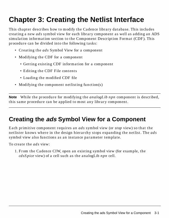
Creating the ads Symbol View for a ComponentEach primitive component requires an ads symbol view (or stop view) so that thenetlister knows where in the design hierarchy stops expanding the netlist. The adssymbol view also functions as an instance parameter template.
To create the ads view:
1. From the Cadence CIW, open an existing symbol view (for example, thecdsSpice view) of a cell such as the analogLib npn cell.
Creating the ads Symbol View for a Component 3-1

Creating the Netlist Interface
2. Choose Design > Save As. The Save As dialog box appears.
3. In the Save As dialog box, change the View Name field to ads and click OK. Thiscreates the ads view in the analogLib database for the npn cell.
Alternatively, you can use the following procedure:
3-2 Creating the ads Symbol View for a Component
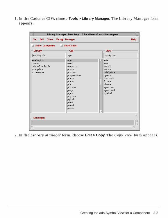
1. In the Cadence CIW, choose Tools > Library Manager . The Library Manager formappears.
2. In the Library Manager form, choose Edit > Copy . The Copy View form appears.
Creating the ads Symbol View for a Component 3-3

Creating the Netlist Interface
3. In the To section of the Copy View dialog box, enter ads in the View field. Ensurethat all other pertinent information is correct, then click OK.
Modifying the Component Description FormatTo modify the Component Description Format (CDF) information for a particularlibrary component, you need the following information:
• A list of ADS instance parameters for the component. For more information,refer to “Getting Device Parameters” on page 2-1.
• The existing CDF information for the component
3-4 Modifying the Component Description Format

Getting Existing CDF Information for a Component
Although there’s more than one way to obtain the CDF for a component, the mostreliable way is to output the existing component CDF to a text file using the SKILLcommand, cdfDump, in the Cadence CIW window. For example:
cdfDump(“analogLib” “/tmp/npn.cdf” ?cellName “npn”)
Editing the CDF File
Edit the CDF information (see Cadence Component Description Format User’s Guide)text file to make modifications (see description of the CDF files contents below).Example:
vi /tmp/npn.cdf
The CDF file consists of two main parts. The first part defines the generic parametersused, for example, width and length. These parameter definitions are shared by allthe supported simulators under Analog Artist. The second part, known as thesimulation information (simInfo) section, details how some subset of theseparameters apply to each different simulator. This section determines how eachcomponent instance is netlisted and how its model arguments and model parametervalues are output in the netlist. The simInfo sub-section of primary interest here isthe ads siminfo sub-section, which needs to be created in order for the component tobe supported by RFIC Dynamic Link.
Example CDF File
The actual CDF file may resemble the following. For conciseness only a few of theCDF parameter definitions and siminfo sub-sections have been shown here and thisfile was obtained as outlined in the previous step. The ads Simulation Informationsub-section is shown highlighted.
/****************************************************/ LIBRARY = "analogLib" CELL = "npn"/****************************************************/
let( ( libId cellId cdfId ) unless( cellId = ddGetObj( LIBRARY CELL ) error( "Could not get cell %s." CELL ) ) when( cdfId = cdfGetBaseCellCDF( cellId ) cdfDeleteCDF( cdfId )
Modifying the Component Description Format 3-5

Creating the Netlist Interface
) cdfId = cdfCreateBaseCellCDF( cellId )
;;; Parameters cdfCreateParam( cdfId ?name "model" ?prompt "Model name" ?defValue "" ?type "string" ?display "artParameterInToolDisplay(’model)" ?parseAsCEL "yes"...;;; Simulator Information cdfId->simInfo = list( nil ) cdfId->simInfo->ads = ’( nil termMapping nil netlistProcedure IdfDevPrim instParameters (Area Region Temp Mode Noise) otherParameters (model bn) propMapping (nil Area area Region region) typeMapping (nil model model) componentName (expr iPar(’model)) termOrder (C B E progn(bn)) current port namePrefix "Q" )
...
Using the CDF Editor
An alternative method for editing the component CDF is by using the CDF editor.From the CIW, choose Tools > CDF > Edit. A dialog box enabling you to create ormodify a cell’s CDF information appears.
3-6 Modifying the Component Description Format

In the dialog box, add or modify the desired information. Ensure the CDF Type is setto Base .
Note To save CDF Edit dialog box changes, you must edit the base-level CDF andhave write permission to the library.
In the Simulation Information section of the Edit Component CDF dialog box, clickEdit to view the simInfo.
An Edit Simulation Information dialog box appears.
Modifying the Component Description Format 3-7

Creating the Netlist Interface
Note While the CDF Edit Simulation Information form may be used to edit theCDF, it is more useful to verify what is in the CDF database. Using cdfDump() and atext editor is more reliable for editing the CDF.
Adding CDF Simulation Information for ADS
A detailed explanation of the CDF information fields is provided in the references.However, in addition, the following applies to RFIC Dynamic Link/ADS:
• netlistProcedure: Use the built-in netlisting functions IdfDevPrim fordevices requiring models (e.g., npn, nmos), IdfCompPrim for devices for which amodel is not required or is optional (e.g., cap, res) and IdfSubcktCall forsubcircuits.
• otherParameters: These are special parameters that apply to thecomponent instance but are NOT netlisted as instance parameters (e.g., model,bn). These parameters appear in the Edit Object Properties Form and the CDFEdit Form and are output to the netlist only if they have a value. If the value of
3-8 Modifying the Component Description Format
any of these parameters is required to be netlisted (e.g., model value for atransistor) it should be given a value or default value (defValue field) in theCDF parameter definition section, otherwise the ADS simulator reports anerror.
• instParameters: This is a list of all parameters that are netlisted as instanceparameters of this component, in the form name=value, such as L, W. Theseparameters appear in the Edit Object Properties Form and the CDF Edit Formand are output to the netlist only if they have a value. If the value of any ofthese parameters is required to be netlisted (for example, R value for a resistor)it should be given a value or default value (defValue field) in the CDFparameter definition section, otherwise the ADS simulator reports an error.
• modelArguments: ADS does not support passing arguments directly to themodel using this field. To pass parameters to a model it is necessary toimplement the model as a subnetwork, include a model card in the subnetworkand pass parameters to the subnetwork using the instParameters field. Soalways leave out this field or set it to nil.
• macroArguments: This field is needed to pass parameters to subnetworkinstances. For primitive devices leave this field blank or set it to nil.
• componentName: The content of this field is netlisted as the componentname of the instance. For devices using models the component name is thename of the model. The componentName field may be set to an AnalogExpression Language (AEL) expression, e.g., expr(iPar(‘model)) for an npn. Thefile naming convention is <model>.<suffix> and can be any name you choose(e.g. npn1.ads). In the Model name field of the Edit Object Properties form,enter the model name. The RFIC Dynamic Link configuration file specifies thesuffix and also the search path for the model file(s). This enables the netlister todetermine which model file to include in the netlist when it outputs a giveninstance.
• termOrder: This field specifies the order in which the terminals arenetlisted. This information is obtained for each ADS component by entering:
hpeesofsim –help <device_name>
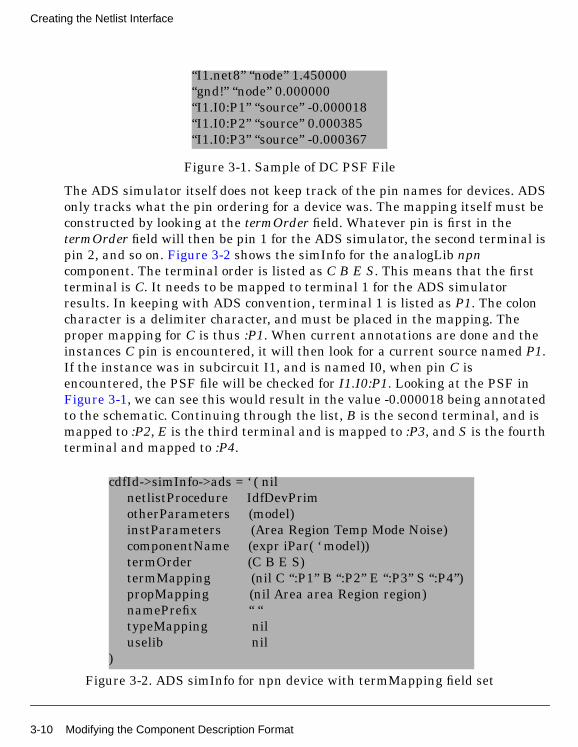
• termMapping: This field defines the mapping between the pins/terminals inthe schematic/symbol and the currents in the DC PSF file (see Figure 3-1). Thismapping is used to back annotate DC simulation results for currents to theschematic. Node voltages are annotated based on the node name, not the pinname, so this field has no effect on voltage annotation.
Modifying the Component Description Format 3-9
Creating the Netlist Interface
Figure 3-1. Sample of DC PSF File
The ADS simulator itself does not keep track of the pin names for devices. ADSonly tracks what the pin ordering for a device was. The mapping itself must beconstructed by looking at the termOrder field. Whatever pin is first in thetermOrder field will then be pin 1 for the ADS simulator, the second terminal ispin 2, and so on. Figure 3-2 shows the simInfo for the analogLib npncomponent. The terminal order is listed as C B E S. This means that the firstterminal is C. It needs to be mapped to terminal 1 for the ADS simulatorresults. In keeping with ADS convention, terminal 1 is listed as P1. The coloncharacter is a delimiter character, and must be placed in the mapping. Theproper mapping for C is thus :P1. When current annotations are done and theinstances C pin is encountered, it will then look for a current source named P1.If the instance was in subcircuit I1, and is named I0, when pin C isencountered, the PSF file will be checked for I1.I0:P1. Looking at the PSF inFigure 3-1, we can see this would result in the value -0.000018 being annotatedto the schematic. Continuing through the list, B is the second terminal, and ismapped to :P2, E is the third terminal and is mapped to :P3, and S is the fourthterminal and mapped to :P4.
Figure 3-2. ADS simInfo for npn device with termMapping field set
“I1.net8” “node” 1.450000“gnd!” “node” 0.000000“I1.I0:P1” “source” -0.000018“I1.I0:P2” “source” 0.000385“I1.I0:P3” “source” -0.000367
cdfId->simInfo->ads = ‘ ( nil netlistProcedure IdfDevPrim otherParameters (model) instParameters (Area Region Temp Mode Noise) componentName (expr iPar( ‘ model)) termOrder (C B E S) termMapping (nil C “:P1” B “:P2” E “:P3” S “:P4”) propMapping (nil Area area Region region) namePrefix “ “ typeMapping nil uselib nil)
3-10 Modifying the Component Description Format

For Bi-directional elements, it turns out that the ADS simulator will onlyoutput a single current value. A case in point is the ADS R element (an idealresistor). In order to annotate both pins, it becomes necessary to specify thatone pin is the negative of the other pin (in other words, current enters throughone pin (+), and leaves through the other pin (-)). This mapping can be achievedby placing a key word of minus. in front of the mapped pin name. Figure 3-3displays the analogLib res simInfo, where bi-directional mapping has beendone. The termOrder field is PLUS MINUS. PLUS has been mapped to :P1, aswould be expected. However, MINUS has been mapped to :minus.P1. Thisspecifies to the annotation code that, when MINUS is encountered, the currentfor the positive terminal should be retrieved, and it’s value should be multipliedby -1.
Figure 3-3. ADS simInfo for res device showing the minus keyword in termMapping
The termMapping field does not need to be set for hierarchical devices.Hierarchical circuits will descend into the hierarchy and retrieve the currentsof all devices attached to a port, and add them together. This does make itcritical that the minus key word be used properly on bi-directional devices. Ifminus is not used, when the currents are added up at a port, the value that isannotated will not be correct. Regrettably, even if a termMapping is set up for ahierarchical device, and an entry exists in the PSF file, it will still not be used,the internal Cadence code will always descend into the hierarchy and add upthe values.
cdfId->simInfo->ads = ‘ ( nil netlistProcedure IdfCompPrim otherParameters (wPmax wImax Model) instParameters (R Temp Tnom TC1 TC2 Width Length Noise) componentName R termOrder (PLUS MINUS) termMapping (nil PLUS “:P1” MINUS “:minus.P1”) propMapping (nil R r Tnom tnom TC1 tc1 TC2 tc2 Width w Length l Model model Noise isnoisy) namePrefix “ “ typeMapping nil uselib nil)
Modifying the Component Description Format 3-11

Creating the Netlist Interface
Note Voltages and Currents will only be annotated on pins that have anassociated cdsTerm. This is true for primitive devices as well as for hierarchicalsubcircuits.
• propMapping: This allows parameter definitions to be reused or shared eventhough they have different names (for use by different simulators) and acts asan aliasing mechanism. For instance, the parameter named Area used by ADSis mapped to area which most other simulators use. In fields likeinstParameters and otherParameters, the simulator-specific name (e.g., Area)should be used.
• namePrefix: Used as a prefix for instance names.
• typeMapping: This field is used to call a built-in SKILL function to netlistcertain types of parameters, whenever they are given a value. e.g.,mapping aproperty to type substrate for microwave library components will cause theIdfPrintSubstrate() function to be called whenever Subst has a value:
propMapping(nil Subst subName)typeMapping(nil Subst substrate)
To get a list of all such mappings, type the following in the CIW:
asiGetNetlistOption(asiGetTool(’ads) ’propTypeMapping))
Note The following simInfo fields are not used by RFIC Dynamic Link/ADS:parameters, model, modelName, permuteRule, deviceTerminals.
The npn has been instantiated as shown in the figure below with the connectingwires named according to the device terminals.
3-12 Modifying the Component Description Format
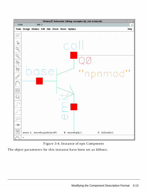
Figure 3-4. Instance of npn Component
The object parameters for this instance have been set as follows:
Modifying the Component Description Format 3-13

Creating the Netlist Interface
The instance statement on the ADS netlist corresponding to this instance will appearas follows:
...npnmod:Q0 coll base emit 0 Area=2.0 Region=1 Temp=25.0...
The following model file will also be appended to the netlist:
...model npnmod BJT NPN=yes Is=4.598E-16 Bf=175 Nf=0.9904 Vaf=22 \Ikf=0.8 Ise=1.548E-14 Ne=1.703 Br=76.1 Nr=0.9952 Var=2.1 \Ikr=0.02059 Isc=3.395E-16 Nc=1.13 Rb=8 Irb=8E-05 \Rbm=3 Re=0.45 Rc=6 Xtb=0 Eg=1.11 Xti=3 Cje=8.7E-13 \Vje=0.905 Mje=0.389 Cjc=3.6E-13 Vjc=0.4907 Mjc=0.2198 \Xcjc=0.43 Tf=1e-11 Xtf=50 Vtf=test(AAA) Itf=0.32 Ptf=32 \Tr=1E-09 Fc=0.6...
3-14 Modifying the Component Description Format

The instance statement on the ADS netlist corresponding to this instance containsthe following parameters:
• npnmod The netlister evaluates the expression contained in thecomponentName CDF field and in this case picks up the value of the modelname property (expr ipar(‘model) ). The netlister also appends the content ofthe npnmod.ads file.
• Q0 The instance name is generated by using the contents of the namePrefixCDF field and appending an incremental number (i.e. Q0, Q1, Q2,...).
• coll base emit 0 The first three entries are taken from the names of the nodesto which the device is attached (see Figure 3-4). In this case, the names havebeen explicitly assigned but the same applies to system generated node names.The termOrder field in the CDF controls the order in which the terminals arenetlisted.
Note The progn SKILL function is no longer supported by RFIC Dynamic Linkin Cadence version 4.4.5 and above.
• Area=2.0 Region=1 Temp=25.0 The parameters Area, Region and Temp arelisted in the instParameters field of the component CDF, therefore they arenetlisted as instance properties if their value has been set on the instance. Ifthe field is left blank, the parameter is not netlisted and the simulator uses thedefault value.
• model npnmod … The netlister appends the contents of the file <Modelname>.ads (if the IDF_MODEL_SUFFIX variable is set to the default value),which in this case is the model file for npnmod.
Additional Notes for Simulation Information Fields
• All simInfo parameters that apply to the Microwave and hpmns CadenceAnalog Artist interfaces also apply to the ads simulator view. An example ofsuch a parameter is typeMapping.
• When errors in the CDF file are loaded with load <file>, command errors maynot be reported. If this occurs, the corresponding ads simulation view for thedevice is not created.
Modifying the Component Description Format 3-15
Creating the Netlist Interface
Loading the Modified CDF File
After modifying the CDF text file to support ADS, load the edited file from the CIWusing the SKILL command, load. For example:
load “/tmp/npn.cdf”
This automatically updates the Cadence library database and saves the new CDFinformation in the database, provided you have write permissions.
Modifying the Component Netlisting Function(s)Each simulator can use its own netlist function to write out a component instance inits own netlist format. Two built-in component-netlisting procedures are available inthe RFIC Dynamic Link SKILL context:
• IdfDevPrim is used for components that always need a model (a transistor, forexample)
• IdfCompPrim is used for components that may or may not need models (aresistor, for example)
You probably won’t need to modify or replace these functions. But if you do, theSKILL code for these built-in functions is provided in:
$IDF_INSTALL_DIR/skill/netlistFuncs.il
3-16 Modifying the Component Netlisting Function(s)

Chapter 4: Creating Model FilesThis chapter describes how to create ASCII-text process-dependent model files,formatted for ADS. These files are stored separate from the Cadence librarydatabase, in a model library directory. The netlister will simply append the model fileto the final top-level ADS netlist without a syntax check. The ADS simulator requiresthe syntax of these files to be exact.
To build model files in ADS format, you’ll need the following information:
• The basic built-in ADS component parameter information (refer to “GettingDevice Parameters” on page 2-1).
• The ADS Simulator Input format information (refer to Appendix E, “ADSSimulator Input Syntax” on page -1).
This chapter describes the following tasks:
• “Creating a Simple ADS Model File” on page 4-1
• “Creating a Parametric Subnetwork Model File” on page 4-2
• “Defining Instance Parameters using Expressions” on page 4-2
• “Defining Model Parameters using Expressions” on page 4-3
• Creating Process Parameter Files
• Linking the ADS Model File to a Library Component
Creating a Simple ADS Model FileOnce the model parameters are known, you can create an ADS model file using anASCII text editor. In your text editor window, type in the complete model statementin the appropriate format for the selected device as defined in part 3 of “ViewingDevice Output” on page 2-2. As you build the ADS model file, be aware of thefollowing:
• The model statement must be on a single line. Use the backslash (\) as a linecontinuation character.
• The instance and model parameter names are case sensitive.
• If a parameter is not specified, ADS uses a default parameter value. Thesevalues are documented in volume 1 of the ADS “Circuit Components” manual.
Creating a Simple ADS Model File 4-1
Creating Model Files
Example:
model npn BJT NPN=yes Is=4.598E-16 Bf=175 Nf=0.9904 Vaf=22 \Ikf=0.8 Ise=1.548E-14 Ne=1.703 Br=76.1 Nr=0.9952 Var=2.1 \Ikr=0.02059 Isc=3.395E-16 Nc=1.13 Rb=8 Irb=8E-05 \Rbm=3 Re=0.45 Rc=6 Xtb=0 Eg=1.11 Xti=3 Cje=8.7E-13 \Vje=0.905 Mje=0.389 Cjc=3.6E-13 Vjc=0.4907 Mjc=0.2198 \Xcjc=0.43 Tf=1e-11 Xtf=50 Vtf=1.2 Itf=0.32 Ptf=32 \Tr=1E-09 Fc=0.6
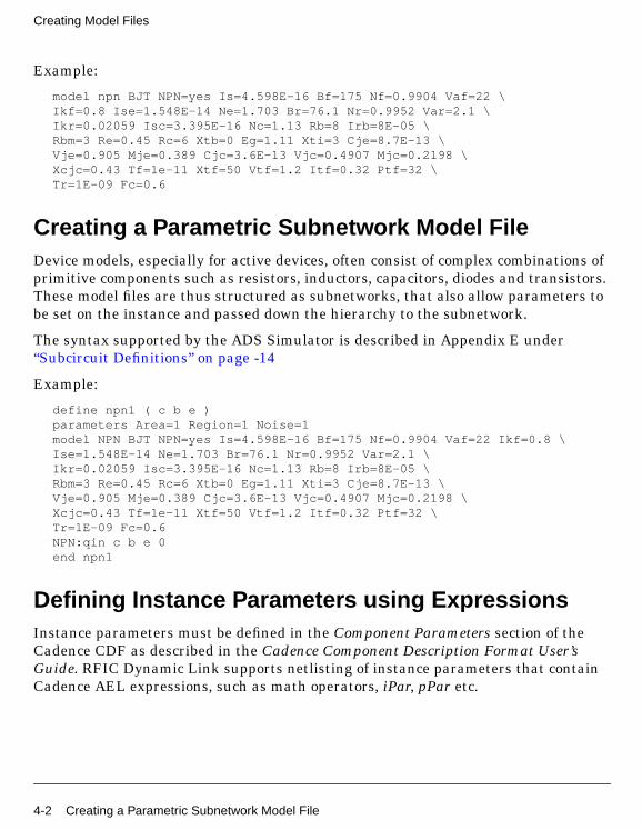
Creating a Parametric Subnetwork Model FileDevice models, especially for active devices, often consist of complex combinations ofprimitive components such as resistors, inductors, capacitors, diodes and transistors.These model files are thus structured as subnetworks, that also allow parameters tobe set on the instance and passed down the hierarchy to the subnetwork.
The syntax supported by the ADS Simulator is described in Appendix E under“Subcircuit Definitions” on page -14
Example:
define npn1 ( c b e )parameters Area=1 Region=1 Noise=1model NPN BJT NPN=yes Is=4.598E-16 Bf=175 Nf=0.9904 Vaf=22 Ikf=0.8 \Ise=1.548E-14 Ne=1.703 Br=76.1 Nr=0.9952 Var=2.1 \Ikr=0.02059 Isc=3.395E-16 Nc=1.13 Rb=8 Irb=8E-05 \Rbm=3 Re=0.45 Rc=6 Xtb=0 Eg=1.11 Xti=3 Cje=8.7E-13 \Vje=0.905 Mje=0.389 Cjc=3.6E-13 Vjc=0.4907 Mjc=0.2198 \Xcjc=0.43 Tf=1e-11 Xtf=50 Vtf=1.2 Itf=0.32 Ptf=32 \Tr=1E-09 Fc=0.6NPN:qin c b e 0end npn1
Defining Instance Parameters using ExpressionsInstance parameters must be defined in the Component Parameters section of theCadence CDF as described in the Cadence Component Description Format User’sGuide. RFIC Dynamic Link supports netlisting of instance parameters that containCadence AEL expressions, such as math operators, iPar, pPar etc.
4-2 Creating a Parametric Subnetwork Model File

Defining Model Parameters using ExpressionsModel parameters contained in ADS model files can include expressions. Theexpressions can be defined by arbitrary combinations of predefined ADS functions,math operators and Boolean operators. For a list of functions and operatorssupported by ADS, refer to Appendix E, “ADS Simulator Input Syntax” on page -1.
For an expression to be correctly evaluated by ADS, both the syntax of the expressionand the value of the variables used in the expression must be defined in one of thefollowing places:
1. directly in the model file,
2. in a separate file which is included in the top level netlist,
3. in a separate file which is included in the model file, or
4. on the ADS top level schematic in a VarEqn block.
Note These different methods can be used in combination, with expressions definedin different places, as long as there is a single definition for each expression.
Example:
This model file for a BJT contains a model parameter, Vtf, that is defined as anexpression of the variable AAA.
model npn BJT NPN=yes Is=4.598E-16 Bf=175 Nf=0.9904 Vaf=22 Ikf=0.8 \ Ise=1.548E-14 Ne=1.703 Br=76.1 Nr=0.9952 Var=2.1 \ Ikr=0.02059 Isc=3.395E-16 Nc=1.13 Rb=8 Irb=8E-05 \ Rbm=3 Re=0.45 Rc=6 Xtb=0 Eg=1.11 Xti=3 Cje=8.7E-13 \ Vje=0.905 Mje=0.389 Cjc=3.6E-13 Vjc=0.4907 Mjc=0.2198 \ Xcjc=0.43 Tf=1e-11 Xtf=50 Vtf=test(AAA) Itf=0.32 Ptf=32 \ Tr=1E-09 Fc=0.6
In order to simulate this model in ADS, the expression test needs to be defined and avalue must be given to the variable AAA.
Assuming that:
test(x)=x*1.2AAA=1
Defining Model Parameters using Expressions 4-3

Creating Model Files
Do one of the following:
1. Append the definition of test and AAA to the model file:
model npn BJT NPN=yes Is=4.598E-16 Bf=175 Nf=0.9904 Vaf=22 Ikf=0.8 \... Xcjc=0.43 Tf=1e-11 Xtf=50 Vtf=test(AAA) Itf=0.32 Ptf=32 \ Tr=1E-09 Fc=0.6 test(x)=x*1.2 AAA=1
2. Create a separate ASCII file (for example, function.inc) containing thedefinition of test and AAA. Then place a geminiInclude instance on the top levelADS schematic by typing geminiInclude (case sensitive) in the ComponentHistory field.
The File parameter should contain the full path of the ASCII file. When thiscomponent is netlisted by ADS, it generates a #include statement that is laterreplaced by the contents of the ASCII file. For more information on fileinclusion, refer to Appendix E, “File Inclusion” on page -38.
The geminiInclude component can thus be used to append a file containingmultiple models or even the entire set of models. It can also be used to select
Component History
File Parameter
4-4 Defining Model Parameters using Expressions

among various files containing different sets of process parameterscorresponding to different corner cases.
In a practical example, typical.inc could contain the process parameter values(sheet resistance, area capacitance, etc.) for the typical case, whilemaximum.inc would have definitions corresponding to the maximum case. ThegeminiInclude component can then be used to select which corner case tosimulate by pointing to either typical.inc or maximum.inc.
3. Include the ASCII file with the expression definitions directly in the model file.
model npn BJT NPN=yes Is=4.598E-16 Bf=175 Nf=0.9904 Vaf=22 Ikf=0.8 \... Xcjc=0.43 Tf=1e-11 Xtf=50 Vtf=test(AAA) Itf=0.32 Ptf=32 \ Tr=1E-09 Fc=0.6 #include “/users/home/functions.inc”
4. Use a VAR block in the ADS top level schematic that contains the expressiondefinitions. For more information on the VAR block, refer to the “VAR (Variablesand Equations Component)” in the ADS Circuit Components manual.
Defining Model Parameters using Expressions 4-5

Creating Model Files
Note If an expression is used to define a model parameter, the argument cannot beanother model parameter or an instance parameter. If the model needs to use thevalue of an instance parameter in the calculation of a model parameter, this requirescreating a subcircuit that incorporates the model, as in the following example:
define npn1 ( c b e )parameters AAA=1 Area=1 Region=1 Noise=1model NPN BJT NPN=yes Is=4.598E-16 Bf=175 Nf=0.9904 Vaf=22 Ikf=0.8 \Ise=1.548E-14 Ne=1.703 Br=76.1 Nr=0.9952 Var=2.1 \Ikr=0.02059 Isc=3.395E-16 Nc=1.13 Rb=8 Irb=8E-05 \Rbm=3 Re=0.45 Rc=6 Xtb=0 Eg=1.11 Xti=3 Cje=8.7E-13 \Vje=0.905 Mje=0.389 Cjc=3.6E-13 Vjc=0.4907 Mjc=0.2198 \Xcjc=0.43 Tf=1e-11 Xtf=50 Vtf=test(AAA) Itf=0.32 Ptf=32 \Tr=1E-09 Fc=0.6NPN:qin c b e 0end npn1
4-6 Defining Model Parameters using Expressions
Appendix A: ReferencesThe following references supplement the information in this book. All the Cadencemanuals are available in Cadence Openbook.
[1]Cadence Component Description Format User’s Guide
[2] Cadence Design Framework II/Library Manager Help
[3] Cadence Analog Artist SKILL Reference
[4] Cadence SKILL Language Reference Manual
[5] Cadence SKILL User Guide
[6] ADS “Expressions, Measurements, and Simulation Data Processing”
A-1

References
A-2

Appendix B: Adding CDF/SimInfo to aComponent LibraryThe chapter provides information on modifying the Cadence simInfo (SimulationInformation) section in a CDF (Component Description Format) file.
Using cdfDumpAllThe benefit of adding simulator information via cdfDumpAll is that you need nothave numerous files containing specific simulation parameters and simInfo. Instead,all of the CDF information is compiled for you in a single ASCII file. This method isprobably your best choice if you do not have source files for parameter and simInfodata for each and every simulator that a library currently supports.
Dumping the CDF for an Entire Component Library
To create and modify an ASCII file containing the entire CDF for an existingcomponent library:
• Enter the following Skill command in the Cadence CIW:
cdfDumpAll(“libName” “fileName” ?edit t)
• In the text editor of your choice (vi, emacs, etc.), for each library cell add thesimInfo for the new simulator ads to the CDF file. In some cases, you may alsoneed to add new CDF parameters.
• Load this file in the CIW using the command:
load “fileName”
This modifies the library database accordingly, assuming you have writepermission to the library.
Dumping the CDF for Individual Components
To create and modify an ASCII file containing the CDF for an individual component:
• Enter the following Skill command in the Cadence CIW:
cdfDump(“libName” “fileName” ?cellName “cellName” ?edit t)
B-1

Adding CFD/SimInfo to a Component Library
• In the text editor of your choice (vi, emacs, etc.), for each library cell add thesimInfo for the new simulator ads to the CDF file. In some cases, you may alsoneed to add new CDF parameters.
• Load this file in the CIW using the command:
load <fileName>
This modifies the library database accordingly, assuming you have writepermission to the library.
Using the Edit Component CDF FormAdding CDF information via the Edit Component CDF form is the ideal method forthose who are not computer programmers. It is also often the best method to usewhen changes to only a few cells are required.
To add new CDF information via the Edit Component CDF form:
• From the CIW, choose Tools > CDF > Edit. A dialog box enabling you to create ormodify a cell’s CDF information appears.
B-2
• In the dialog box, add or modify the desired information.
Note To save changes to the Edit Component CDF form, you must edit thebase-level CDF and have write permission to the library.
For more details on using the Edit Component CDF form, refer to the CadenceComponent Description Format User’s Guide [1].
Note If you are adding a CDF entry for a new simulator, the tool filter file mustreflect this before the entry appears in the dialog box’s simulation information(simInfo) section. For more information, refer to the Cadence Component DescriptionFormat User Guide.
B-3

Adding CFD/SimInfo to a Component Library
B-4

Appendix C: Modifying the basic LibraryRFIC Dynamic Link requires that the basic library nlpglobals cell contains the adsview. A version of the basic library is located in
$IDF_INSTALL_DIR/cdslib4.4.*/basic
Alternatively, you may modify your site’s version of the basic library located in:
<Cadence_install_dir>/tools/dfII/etc/cdslib/basic
To do this:
• Using the Cadence Schematic window, edit the spectre view of cell nlpglobals.
• Save this view as the ads view.
C-1

Modifying the basic Library
C-2

Appendix D: Modifying the analogLib LibraryThe RFIC Dynamic Link install package includes a version of Cadence analogLibthat has been extended to work with ADS and is located in:
$IDF_INSTALL_DIR/cdslib/4.4.*/analogLib
However, if you need to extend your own version of analogLib to work with ADS, thisappendix may be useful.
To modify your version of analogLib:
1. Make a temporary directory called adsLib at the current level then change tothe newly created adsLib directory.
2. Copy your version of analogLib to your current (adsLib) directory. Take care touse a method, such as UNIX tar, that will preserve the file dates and accesscodes.
AnalogLib is usually located in:
$IDF_CDS_DIR/tools/dfII/etc/cdslib/artist/
3. Copy the official versions of some or all of the following simulator directories(usually located under $IDF_CDS_DIR/tools/dfII/src/artist/) to your currentdirectory.
auCdlauLvscdsSpicehpmnshspiceSlibramicrowavespectrespectreSspice2
The above directories are listed in alphabetical order. Each should containsimInfo.il files for the respective simulators.
Note Instead of copying these directories, you may want to make symboliclinks to them.
D-1

Modifying the analogLib Library
4. Create a one-line cds.lib file that defines analogLib. The content of the cds.libfile should contain:
DEFINE analogLib ./analogLib
5. Enter the command:
makeAnalogLib
6. Copy the newly created analogLib to whatever location you desire, such as:
$IDF_CDS_DIR/tools/dfII/etc/cdslib/artist/analogLib
You are now able to simulate in ADS using the modified analogLib library.
Using almBuildLibrary in a UNIX Shell ScriptThe Analog Artist Skill function almBuildLibrary compiles the simulationinformation for various simulators into a given library. For each such library, you willneed to write a UNIX shell script that essentially starts icms in non-graphics modeand then runs almBuildLibrary.
The following is an example script for analogLib, a variation of which can usually befound in <Cadence_install_dir>/tools/dfII/src/artist/analogLib/makeAnalogLib:
#!/bin/csh -f
echo Building library.../bin/rm -f CDS.logcat << EOF > tmp.il\i printf(“Loading tmp.il...”)\i lib = “analogLib”\i sourcePath = “.”\i simulators = ‘( ads auCdl auLvs cdsSpice hpmns hspiceS libra spectre \spectreS spice2 hpmns )\i ddGetObj( lib )\i sstatus( writeProtect nil)\i load(“./ads/params.il”)\i load(“./ads/labels.il”)\i (almBuildLibrary ?lib lib ?sourcePath sourcePath ?simulatorssimulators)\i exit()EOF
icms -replay ./tmp.il -nograph -log ./CDS.log
D-2

For this example script to work, there must be:
• a copy of analogLib in the current directory
• a subdirectory for each of the simulators
• and each simulator directory must contain a file called simInfo.il.
Your directory structure should be similar to the following:
This procedure is documented in more detail in the Cadence Component DescriptionFormat User’s Guide [1].
adsLib/analogLibcds.libmakeAnalogLibads/
params.illabels.ilsimInfo.il
spectre/simInfo.il
...
D-3

Modifying the analogLib Library
D-4

Appendix E: ADS Simulator Input SyntaxThis chapter provides information related to Advanced Design System’s Simulator.While this is not an all inclusive document with regards to the ADS simulator, theinformation provided in this chapter should help you accomplish tasks related to theRFIC Dynamic Link.
Hardware and Operating System RequirementsThe ADS Simulator is supported on the following platforms:
• HP 9000 Series 700, Series 800 and C-class computers, running HP-UX 10 or11.
• SunOS 5.6, 5.7 (aka Solaris 2.5, 2.6, 7.0, 8.0) (Sparcstations).
• IBM RS/6000s running AIX 4.4.3 or later.
• PCs running Windows 95, 98, NT 4.0 (not Windows 2000).
Setting Environment VariablesBefore running the ADS Simulator, the following environment variables must be set:
To set the UNIX environment variables using the Korn Shell, add the following toyour ~/.profile.
export HPEESOF_DIR=<ADS_install_dir>export PATH=$PATH:$HPEESOF_DIR/bin
To set the UNIX environment variables using the C Shell, add the following to your~/.cshrc.
setenv HPEESOF_DIR <ADS_install_dir>setenv PATH $PATH:$HPEESOF_DIR/bin
Table 4-1. ADS Simulator Required Environment Variables
Variable UNIX Setting
HPEESOF_DIR <ADS_install_dir>
PATH $PATH:$HPEESOF_DIR/bin
E-1

ADS Simulator Input Syntax
Using the hpeesofsim CommandThe ADS Simulator can be invoked using the following syntax.
IMPORTANT: Note that the ‘‘-I’’ option is used to include a file and is not used tospecify the location of an include directory. Unfortunately, there is no way to specifyadditional search directories.
If no input file is specified, the ADS Simulator reads the standard input. Note that forconsistency with the C preprocessor, there is no space between the preprocessor flags(-D, -I, -P, -U) and their arguments.
Usage: hpeesofsim [options] [-r rawfile] [inputfile]
Options:
-h List devices and analyses.
-h x Give synopsis of device or analysis ‘x’.
-h functions Give synopsis of all built-in functions.
-h variables Give synopsis of all built-in variables.
-h expressions Give synopsis of all built-in expressions.
-h all Give synopsis of all devices and analyses.
-h help Give format of the parameter descriptions in abovesynopsis.
-q Eliminate all narrative except error messages.
-Dx Define string ‘x’.
-Dx=y Define string ‘x’ to be ‘y’.
-Ilib Prepend ‘lib’ to circuit file.
-N Do not search for libraries.
-C Perform case insensitive processing of names.
-P-x Pass option ‘-x’ to preprocessor.
-Ux Undefine string ‘x’.
E-2

Interpreting this AppendixIn order to make this appendix easier to update and hopefully more accurate, much ofthe information in it is directly derived from the help facility in the ADS Simulator.The parameter information in the help facility has the following format.
Parameters:
name (units) attributes description
Attributes:
field 1: settable
s = settableS = settable and required
field 2: modifiable
m = modifiable
field 3: optimizable
o = optimizable
field 4: readable
r = readable
field 5: type
b = booleani = integerr = real numberc = complex numberd = device instances = character string
E-3

ADS Simulator Input Syntax
Table 4-2. Model Parameter Attribute Definitions
Attribute Meaning Example
settable Can be defined in the instance ormodel statement. Most parametersare settable, there are a few caseswhere a parameter is calculatedinternally and could be used either inan equation or sent to the dataset viathe OutVar parameter on thesimulation component. Theparameter must have its full address.
Gbe (Small signal Base-EmitterConductance) in the BJT model canbe sent to the dataset by settingOutVar=”MySubCkt.X1.Gbe” onthe simulation component.
required Has no default value; must be set tosome value, otherwise the simulatorwill return an error.
modifiable The parameter value can be swept insimulation.
optimizable The parameter value can beoptimized.
readable Can be queried for value in simulationusing the OutVar parameter. Seesettable.
boolean Valid values are 1, 0, True, and False.
integer The maximum value allowed for aninteger type is 32767, values between32767 and 2147483646 are still valid,but will be netlisted as real numbers.In some cases the value of aparameter is restricted to a certainnumber of legal values.
The Region parameter in the BJTmodel is defined as integer but theonly valid values are 0, 1, 2, and 3.
real number The maximum value allowed is1.79769313486231e308+.
complex number The maximum value allowed for thereal and imaginary parts is1.79769313486231e308+.
E-4

There are two other identifiers not in flag format. One is [ ] next to a parameter nameand it means that the parameter is structured as an array. The other is (repeatable)appended to the parameter description and it means that the parameter can appearmore than once in the same instance. An example is OutVar .
Codewording and SecurityThe ADS Simulator is a secured program that requires, at a minimum, a license forthe E8881 Linear Simulator to run. Depending on the type of simulation, additionallicenses may be required. For more information on codewording and security, refer to“Setting Up Licenses on UNIX Systems” in the ADS Installation on UNIX Systemsmanual.
General SyntaxIn this appendix, the following typographical conventions apply:
device instance The parameter value must be set tothe name of one of the instancespresent in the circuit.
The mutual inductance component(Mutual), where the parametersInductor1 and Inductor2 are definedby instance names of inductorspresent in the circuit or by a variablepointing to the instance names.Inductor1=”L1” or Inductor1=Xyzwhere Xyz=”L1”
character string Used typically for file names. Must bein double quotes.
Filename=”MyFileName”
Table 4-3. Typographic Conventions
Type Style Used For
[. . .] Data or character fields enclosed in brackets are optional.
italics Names and values in italics must be supplied
bold Words in bold are ADS simulator keywords and are alsorequired.
Table 4-2. Model Parameter Attribute Definitions
Attribute Meaning Example
E-5

ADS Simulator Input Syntax
The ADS Simulator SyntaxThe following sections outline the basic language rules.
Field Separators
A delimiter is one or more blanks or tabs.
Continuation Characters
A statement may be continued on the next line by ending the current line with abackslash and continuing on the next line.
Name Fields
A name may have any number of letters or digits in it but must not contain anydelimiters or non alphanumeric characters. The name must begin with a letter or anunderscore ( _ ).
Table 4-4. Fundamental Units
Dimension Fundamental Unit
Frequency Hertz
Resistance Ohms
Conductance Siemens
Capacitance Farads
Inductance Henries
Length meters
Time seconds
Voltage Volts
Current Amperes
Power Watts
Distance meters
Temperature Celsius
E-6

Parameter Fields
A parameter field takes the form name = value, where name is a parameter keywordand value is either a numeric expression, the name of a device instance, the name of amodel or a character string surrounded by double quotes. Some parameters can beindexed, in which case the name is followed by [i], [i,j], or [i,j,k]. i, j, and k must beinteger constants or variables.
Node Names
A node name may have any number of letters or digits in it but must not contain anydelimiters or non alphanumeric characters. If a node name begins with a digit, thenit must consist only of digits.
Lower/Upper Case
The ADS Simulator is case sensitive.
Units and Scale Factors
An integer or floating point number may be scaled by following it with either an e orE and an integer exponent (e.g., 2.65e3, 1e-14).
An ADS Simulator parameter with a given dimension assumes its value has thecorresponding units. For example, for a resistance, R=10 is assumed to be 10 Ohms.The fundamental units for the ADS Simulator are shown in Table 4-4.
A number or expression can be scaled by following it with a scale factor. A scale factoris a single word that begins with a letter or an underscore. The remaining characters,if any, consist of letters, digits, and underscores. Note that ‘‘/’’ cannot be used torepresent ‘‘per’’. The value of a scale factor is resolved using the following rule: If thescale factor exactly matches one of the predefined scale-factors (Table 4-5), then usethe numerical equivalent; otherwise, if the first character of the scale factor is one ofthe legal scale-factor prefixes (Table 4-6), the corresponding scaling is applied.
E-7

ADS Simulator Input Syntax
Predefined Scale Factors
This type of scale factor is a predefined sequence of characters which the ADSSimulator parses as a single token. The predefined scale factors are listed inTable 4-5.
Table 4-5. Predefined Scale Factors
Scale Factor Scaling Meaning
A 1 Amperes
F 1 Farads
ft 0.3048 feet
H 1 Henries
Hz 1 Hertz
in 0.0254 inches
meter 1 meters
meters 1 meters
metre 1 meters
metres 1 meters
mi 1609.344 miles
mil 2.54*10-5 mils
mils 2.54*10-5 mils
nmi 1852 nautical miles
Ohm 1 Ohms
Ohms 1 Ohms
S 1 Siemens
sec 1 seconds
V 1 Volts
W 1 Watts
E-8

Single-character prefixes
If the first character of the scale factor is one of the legal scale-factor prefixes, thecorresponding scaling is applied.The single-character prefixes are based on themetric system of scaling prefixes and are listed in Table 4-6.
For example, 3.5 GHz is equivalent to 3.5*10 9 and 12 nF is equivalent to 1.2*10 -8.Note that most of the time, the ADS Simulator ignores any characters that follow thesingle-character prefix. The exceptions are noted in the section on “UnrecognizedScale Factors” on page -10.
Most of these scale factors can be used without any additional characters (e.g., 3.5 G ,12n ). This means that m, when used alone, stands for ‘‘milli’’.
The underscore _ is provided to turn off scaling. For example, 1e-9 _farad isequivalent to 10-9, and 1e-9 farad is equivalent to 10-24.
Predefined scale factors are case sensitive.
Unless otherwise noted, additional characters can be appended to a predefined scalefactor prefix without affecting its scaling value.
Table 4-6. Single-character prefixes
Prefix Scaling Meaning
T 1012 tera
G 109 giga
M 106 mega
K 103 kilo
k 103 kilo
- 1
m 10-3 milli
u 10-6 micro
n 10-9 nano
p 10-12 pico
f 10-15 femto
a 10-18 atto
E-9

ADS Simulator Input Syntax
A predefined scale factor overrides any corresponding single-character-prefix scalefactor. For example, 3 mm is equivalent to 3*10-3, not 3*106. In particular, note thatM does not stand for milli, m does not stand for mega, and F does not stand for femto.
There are no scale factors for dBm, dBW, or temperature. For more information, referto the section on “Functions” on page -19 for conversion functions.
Unrecognized Scale Factors
The ADS Simulator treats unrecognizable scale factors as equal to 1 and generates awarning message.
Scale-Factor Binding
More than one scale factor may appear in an expression, so expressions like x in + y
mil are valid and behave properly.
Scale factors bind tightly to the preceding variable. For instance, 6 + 9 MHz is equalto 9000006 . Use parentheses to extend the scope of a scale factor (e.g., (6 + 9) MHz ).
Booleans
Many devices, models, and analyses have parameters that are boolean valued. Zero isused to represent false or no, whereas any number besides zero represents true oryes. The keywords yes and no can also be used.
Ground Nodes
Node 0 is assumed to be the ground node. Additional ground node aliases can bedefined using the ground statement. Multiple ground statements can be used todefine any number of ground aliases, but they must all occur at the top-levelhierarchy in the netlist.
General Form:
Ground [ :name ] node1 [... nodeN]
Example:
Ground gnd
E-10
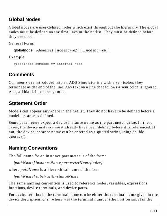
Global Nodes
Global nodes are user-defined nodes which exist throughout the hierarchy. The globalnodes must be defined on the first lines in the netlist. They must be defined beforethey are used.
General Form:
globalnode nodename1 [ nodename2 ] [... nodenameN ]
Example:
globalnode sumnode my_internal_node
Comments
Comments are introduced into an ADS Simulator file with a semicolon; theyterminate at the end of the line. Any text on a line that follows a semicolon is ignored.Also, all blank lines are ignored.
Statement Order
Models can appear anywhere in the netlist. They do not have to be defined before amodel instance is defined.
Some parameters expect a device instance name as the parameter value. In thesecases, the device instance must already have been defined before it is referenced. Ifnot, the device instance name can be entered as a quoted string using doublequotes (").
Naming Conventions
The full name for an instance parameter is of the form:
[pathName].instanceName.parameterName[index]
where pathName is a hierarchical name of the form
[pathName].subcircuitInstanceName
The same naming convention is used to reference nodes, variables, expressions,functions, device terminals, and device ports.
For device terminals, the terminal name can be either the terminal name given in thedevice description, or tn where n is the terminal number (the first terminal in the
E-11

ADS Simulator Input Syntax
description is terminal 1, etc.). Device ports are referenced by using the name pm,where m is the port number (the first pair of terminals in the device description isport 1, etc.).
Note that t1 and p1 both correspond to the current flowing into the first terminal of adevice, and that t2 corresponds to the current flowing into the second terminal. Ifterminals one and two define a port, then the current specified by t2 is equal andopposite to the current specified by t1 and p1.
Currents
The only currents that can be accessed for simulation, optimization, or outputpurposes are the state currents.
State currents
Most devices are voltage controlled, that is, their terminal currents can be calculatedgiven their terminal voltages. Circuits that contain only voltage-controlled devicescan be solved using node analysis. Some devices, however, such as voltage sources,are not voltage controlled. Since the only unknowns in node analysis are the nodevoltages, circuits that contain non-voltage-controlled devices cannot be solved usingnode analysis. Instead, modified node analysis is used. In modified node analysis, theunknown vector is enlarged. It contains not only the node voltages but the branchcurrents of the non-voltage-controlled devices as well. The branch currents thatappear in the vector of unknowns are called state currents. Since the ADS Simulatoruses modified node analysis, the values of the state currents are available for output.
If the value of a particular current is desired but the current is not a state current,insert a short in series with the desired terminal. The short does not affect thebehavior of the circuit but does create a state current corresponding to the desiredcurrent.
To reference a state current, use the device instance name followed by either aterminal or port name. If the terminal or port name is not specified, the state currentdefaults to the first state current of the specified device. Note that this does notcorrespond to the current through the first port of the device whenever the currentthrough the first port is not a state current. For some applications, the positive statecurrent must be referenced, so a terminal name of t1 or t3 is acceptable but not t2.Using port names avoids this problem. The convention for current polarity is thatpositive current flows into the positive terminal.
E-12

Instance StatementsGeneral Form:
type [ :name ] node1 ... nodeN [ [ param=value ] ... ]
type [ :name ] [ [ param=value] ... ]
Examples:
ua741:OpAmp in out outC:C1 2 3 C=10pfHB:Distortion1 Freq=10GHz
The instance statement is used to define to the ADS Simulator the informationunique to a particular instance of a device or an analysis. The instance statementconsists of the instance type descriptor and an optional name preceded by a colon. Ifit is a device instance with terminals, the nodes to which the terminals of theinstance are connected come next. Then the parameter fields for the instance aredefined. The parameters can be in any order. The nodes, though, must appear in thesame order as in the device or subcircuit definition.
The type field may contain either the ADS Simulator instance type name, or auser-supplied model or subcircuit name. The name can be any valid name, whichmeans it must begin with a letter, can contain any number of letters and digits, mustnot contain any delimiters or non alphanumeric characters, and must not conflictwith other names including node names.
Model StatementsGeneral Form:
model name type [ [ param = value ] ... ]
Examples:
model NPNbjt bjt NPN=yes Bf=100 Js=0.1fa
Often characteristics of a particular type of element are common to a large number ofinstances. For example, the saturation current of a diode is a function of the processused to construct the diode and also of the area of the diode. Rather than describingthe process on each diode instantiation, that description is done once in a modelstatement and many diode instances refer to it. The area, which may be different foreach device, is included on each instance statement. Though it is possible to have
E-13

ADS Simulator Input Syntax
several model statements for a particular type of device, each instance may onlyreference at most one model. Not all device types support model statements.
The name in the model statement becomes the type in the instance statement. Thetype field is the ADS Simulator-defined model name. Any parameter value notsupplied will be set to the model’s default value.
Most models, such as the diode or bjt models, can be instantiated with an instancestatement. There are exceptions. For instance, the Substrate model cannot beinstantiated. Its name, though, can be used as a parameter value for the Substparameter of certain transmission line devices.
Subcircuit DefinitionsGeneral Form:
Examples:
define DoubleTuner (top bottom left right)parameters vel=0.95 r=1.0 l1=.25 l2=.25 tline:tuner1 top bottom left left len=l1 vel=vel r=r tline:tuner2 top bottom right right len=l2 vel=2*vel r=rend DoubleTunerDoubleTuner:InputTuner t1 b2 3 4 l1=0.5
A subcircuit is a named collection of instances connected in a particular way that canbe instantiated as a group any number of times by subcircuit calls. The subcircuit callis in effect and form, an instance statement. Subcircuit definitions are simply circuitmacros that can be expanded anywhere in the circuit any number of times. When an
define subcircuitName ( node1 ... nodeN )
[ parameters name1 = [ value1 ] ... name n = [ value n ] ]
.
.
.
elementStatements
.
.
.
end [ subcircuitName ]
E-14

instance in the input file refers to a subcircuit definition, the instances specifiedwithin the subcircuit are inserted into the circuit. Subcircuits may be nested. Thus asubcircuit definition may contain other subcircuits. However, a subcircuit definitioncannot contain another subcircuit definition. All the definitions must occur at the toplevel.
An instance statement that instantiates a subcircuit definition is referred to as asubcircuit call. The node names (or numbers) specified in the subcircuit call aresubstituted, in order, for the node names given in the subcircuit definition. Allinstances that refer to a subcircuit definition must have the same number of nodes asare specified in the subcircuit definition and in the same order. Node names insidethe subcircuit definition are strictly local unless they are a global ground defined witha ground statement or global nodes defined with a globalnode statement. A subcircuitdefinition with no nodes must still include the parentheses ( ).
Parameter specification in subcircuit definitions is optional. Any parameters that arespecified are referred to by name followed by an equals sign and then an optionaldefault value. If, when making a subcircuit call in your input file, you do not specify aparticular parameter, then this default value is used in that instance. Subcircuitparameters can be used in expressions within the subcircuit just as any othervariable.
Subcircuits are a flexible and powerful way of developing and maintaininghierarchical circuits. Parameters can be used to modify one instance of a subcircuitfrom another. Names within a subcircuit can be assigned without worrying aboutconflicting with the same name in another subcircuit definition. The full name for anode or instance include its path name in addition to its instance name. For example,if the above subcircuit is included in subckt2 which is itself included in subckt1 , thenthe full path name of the length of the first transmission line issubckt1.subckt2.tuner1.len .
Only enough of the path name has to be specified to unambiguously identify theparameter. For example, an analysis inside subckt1 can reference the length bysubckt2.tuner1.len since the name search starts from the current level in thehierarchy. If a reference to a name cannot be resolved in the local level of hierarchy,then the parent is searched for the name, and so on until the top level is searched. Inthis way, a sibling can either inherit its parent’s attributes or define its own.
E-15

ADS Simulator Input Syntax
Expression CapabilityThe ADS Simulator has a powerful and flexible symbolic expression capability, calledVarEqn, which allows the user to define variables, expressions, and functions in thenetlist. These can then be used to define other VarEqn expressions and functions, tospecify device parameters and optimization goals, etc.
The names for VarEqn variables, expressions, and functions follow the samehierarchy rules that instance and node names do. Thus, local variables in a subcircuitdefinition can assume values that differ from one instance of the subcircuit to thenext.
Functions and expressions can be defined either globally or locally anywhere in thehierarchy. All variables are local by default. Local variables are known in thesubcircuit in which they are defined, and all lower subcircuits; they are not known athigher levels. Expressions defined at the root (the top level) are known everywherewithin the circuit. To specify an expression to be global the global keyword mustprecede the expression. The global keyword causes the variable to be defined at theroot of the hierarchy tree regardless of the lexical location.
Examples:
global exp1 = 2.718
The expression capability includes the standard math operations of + - / * ^ inaddition to parenthesis grouping. Scale factors are also allowed in generalexpressions and have higher precedence than any of the math operators. For moreinformation, refer to the previous section on “Units and Scale Factors” on page -7.
Constants
An integer constant is represented by a sequence of digits optionally preceded by anegative sign (e.g, 14, -3 ).
A real number contains a decimal point and/or an exponential suffix using the e
notation (e.g, 14.0 , -13e-10 ).
The only complex constant is the predefined constant j which is equal to the squareroot of -1. It can be used to generate complex constants from real and integerconstants (e.g., j*3 , 9.1 + j*1.2e-2 ). The predefined functions complex() andpolar() can also be used to enter complex constants into an expression.
A string constant is delimited by single quotes (e.g.,’string’ ,’this is a string’ ).
E-16
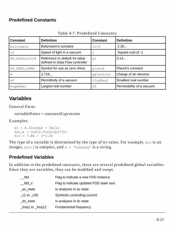
Predefined Constants
Variables
General Form:
variableName = constantExpression
Examples:
x1 = 4.3inches + 3milssyc_a = cos(1.0+sin(pi*3))Zin = 7.8k - j*3.2k
The type of a variable is determined by the type of its value. For example, x=1 is aninteger, x=1+j is complex, and x = “tuesday” is a string.
Predefined Variables
In addition to the predefined constants, there are several predefined global variables.Since they are variables, they can be modified and swept.
Table 4-7. Predefined Constants
Constant Definition Constant Definition
boltzmann Boltzmann’s constant ln10 2.30...
c0 Speed of light in a vacuum j Square root of -1
DF_DefaultInt Reference to default int valuedefined in Data Flow controller
pi 3.14...
DF_ZERO_OHMS Symbol for use as zero ohms planck Planck’s constant
e 2.718... qelectron Charge of an electron
e0 Permittivity of a vacuum tinyReal Smallest real number
hugeReal Largest real number u0 Permeability of a vacuum
__fdd Flag to indicate a new FDD instance
__fdd_v Flag to indicate updated FDD state vars
_ac_state Is analyses in ac state
_c1 to _c30 Symbolic controlling current
_dc_state Is analyses in dc state
_freq1 to _freq12 Fundamental frequency
E-17

ADS Simulator Input Syntax
_harm Harmonic number index for sources and FDD
_hb_state Is analyses in harmonic balance state
_p2dInputPower Port input power for P2D simulation
_sigproc_state Is analyses in signal processing state
_sm_state Is analyses in sm state
_sp_state Is analyses in sparameter analysis state
_tr_state Is analyses in transient state
CostIndex Index for optimization cost plots
DF_Value Reference to corresponding value defined in Data Flowcontroller
DefaultValue Signal processing default parameter value
DeviceIndex Device Index used for noise contribution or DC OP output
dcSourceLevel used for DC source-level sweeping
doeindex Index for Design of Experiment sweeps
freq The frequency in Hertz of the present simulation (1MHz)
logNodesetScale Used for DC nodeset simulation
logRshunt Used for DC Rshunt sweeping
mcTrial Trial counter for Monte Carlo based simulations
noisefreq The spectral noise analysis frequency
Nsample Signal processing analysis sample number
optIter Optimization job iteration counter
temp The ambient temperature, in degrees Celsius. (25o C)
time The analysis time
timestep The analysis time step
tranorder The transient analysis integration order
ScheduleCycle Signal processing schedule cycle number
sourcelevel The relative attenuation of the spectral sources (1.0)
ssfreq The small-signal mixer analysis frequency
_v1 to _v19 State variable voltages used by the sdd device
_i1 to _i19 State variable currents used by the sdd device
mc_index Index variable used by Monte Carlo controller
E-18

The sourcelevel variable is used by the spectral analysis when it needs to graduallyincrease source power from 0 to full scale to obtain convergence. It can be used by theuser to sweep the level of ALL spectral source components, but is not recommended.The _v and _i variables should only be used in the context of the sdd device.
Expressions
General Form:
expressionName = nonconstantExpression
Examples:
x1 = 4.3 + freq;syc_a = cos(1.0+sin(pi*3 + 2.0*x1))Zin = 7.8 ohm + j*freq * 1.9 phy = if (x equals 0) then 1.0e100 else 1/x endif
The main difference between expressions and variables is that a variable can bedirectly swept and modified by an analysis but an expression cannot. Note however,that any instance parameter that depends on an expression is updated whenever oneof the variables that the expression depends upon is changed (e.g., by a sweep).
Predefined Expressions
Functions
General Form:
functionName( [ arg1, ..., argn ] ) = expression
Examples:
gaussian = _gaussian_tol(10.0) default gaussian distribution
nfmin = _nfmin() the minimum noise figure
omega = 2.0*pi*freq the analysis frequency
rn = _rn() the noise resistance
sopt = _sopt the optimum noise match
tempkelvin = temp + 273.15 the analysis temperature
uniform = _uniform_tol(10.0) default uniform distribution
E-19

ADS Simulator Input Syntax
y_srl(freq, r, l) = 1.0/(r + j*freq*l)expl(a,b) = exp(a)*step(b-a) + exp(b)*(a-b-1)*step(a-b)
In expression, the function’s arguments can be used, as can any other VarEqnvariables, expressions, or functions.
E-20

Predefined Functions
_discrete_density(...) user-defined discrete density function
_gaussian( [mean, sigma,lower_n_sigmas,upper_n_sigmas,lower_n_sigmas_del,upper_n_sigmas_del] )
gaussian density function
_gaussian_tol[percent_tol,lower_n_sigmas,upper_n_sigmas,lower_percent_tol,upper_percent_tol,lower_n_sigmas_del,upper_n_sigmas_del] )
gaussian density function (tolerance version)
_get_fnom_freq(...) Get analysis frequency for FDD carrier frequency index andharmonic
_lfsr(x, y, z) linear feedback shift register (trigger, seed, taps)
_mvgaussian(...) multivariate gaussian density function (correlation version)
_mvgaussian_cov(...) multivariate gaussian density function (covariance version)
_n_state(x, y) _n_state(arr, val) array index nearest value
_pwl_density(...) user-defined piecewise-linear density function
_pwl_distribution(...) user-defined piecewise-linear distribution function
_randvar(distribution,mcindex, [nominal,tol_percent, x_min,x_max, lower_tol,upper_tol, delta_tol,tol_factor] )
random variable function
_shift_reg(x, y, z, t) (trigger, mode(ParIn:MSB1st), length, input)
_uniform( [lower_bound,upper_bound] )
uniform density function
_uniform_tol([percent_tol,lower_tol, upper_tol] )
uniform density function (tolerance version)
abs(x) absolute value function
access_all_data(...) datafile indep+dep lookup/interpolation function
E-21

ADS Simulator Input Syntax
access_data(...) datafile dependents’ lookup/interpolation function
arcsinh(x) arcsinh function
arctan(x) arctan function
atan2(y, x) arctangent function (two real arguments)
awg_dia(x) wire gauge to diameter in meters
bin(x) function convert a binary to integer
bitseq(time, [clockfreq,trise, tfall, vlow, vhigh,bitseq] )
bitsequence function
complex(x, y) real-to-complex conversion function
conj(x) complex-conjugate function
cos(x) cosine function
cos_pulse(time, [low,high, delay, rise, fall,width, period] )
periodic cosine shaped pulse function
cosh(x) hyperbolic cosine function
cot(x) cotangent function
coth(x) hyperbolic cotangent function
ctof(x) convert Celsius to Fahrenheit
ctok(x) convert Celsius to Kelvin
cxform(x, y, z) transform complex data
damped_sin(time, [offset,amplitude, freq, delay,damping, phase] )
damped sin function
db(x) decibel function
dbm(x, y) convert voltage and impedance into dbm
dbmtoa(x, y) convert dbm and impedance into short circuit current
dbmtov(x, y) convert dbm and impedance into open circuit voltage
dbmtow(x) convert dBm to Watts
dbpolar(x, y) (dB,angle)-to-rectangular conversion function
dbwtow(x) convert dBW to Watts
E-22
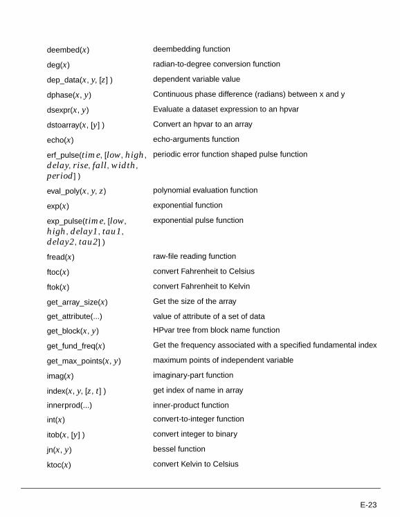
deembed(x) deembedding function
deg(x) radian-to-degree conversion function
dep_data(x, y, [z] ) dependent variable value
dphase(x, y) Continuous phase difference (radians) between x and y
dsexpr(x, y) Evaluate a dataset expression to an hpvar
dstoarray(x, [y] ) Convert an hpvar to an array
echo(x) echo-arguments function
erf_pulse(time, [low, high,delay, rise, fall, width,period] )
periodic error function shaped pulse function
eval_poly(x, y, z) polynomial evaluation function
exp(x) exponential function
exp_pulse(time, [low,high, delay1, tau1,delay2, tau2] )
exponential pulse function
fread(x) raw-file reading function
ftoc(x) convert Fahrenheit to Celsius
ftok(x) convert Fahrenheit to Kelvin
get_array_size(x) Get the size of the array
get_attribute(...) value of attribute of a set of data
get_block(x, y) HPvar tree from block name function
get_fund_freq(x) Get the frequency associated with a specified fundamental index
get_max_points(x, y) maximum points of independent variable
imag(x) imaginary-part function
index(x, y, [z, t] ) get index of name in array
innerprod(...) inner-product function
int(x) convert-to-integer function
itob(x, [y] ) convert integer to binary
jn(x, y) bessel function
ktoc(x) convert Kelvin to Celsius
E-23

ADS Simulator Input Syntax
ktof(x) convert Kelvin to Fahrenheit
length(x) returns number of elements in array
limit_warn( [x, y, z, t, u] ) limit, default and warn function
list(...)
ln(x) natural log function
log(x) log base 10 function
mag(x) magnitude function
makearray(...) (1:real-2:complex-3:string, y, z..) or (array, startIndex, stopIndex)
max(x, y) maximum function
min(x, y) minimum function
multi_freq(time,amplitude, freq1, freq2,n, [seed] )
multifrequency function
names(x, y) array of names of indepVars and/or depVars in dataset
norm(x) norm function
phase(x) phase (in degrees) function
phase_noise_pwl(...) piecewise-linear function for computing phase noise
phasedeg(x) phase (in degrees) function
phaserad(x) phase (in radians) function
polar(x, y) polar-to-rectangular conversion function
polarcpx(...) polar to rectangular conversion function
pulse(time, [low, high,delay, rise, fall, width,period] )
periodic pulse function
pwl(...) piecewise-linear function
pwlr(...) piecewise-linear-repeated function
rad(x) degree-to-radian conversion function
ramp(x) ramp function
read_data(...) read_data("file-dataset", "locName", "fileType")
read_lib(...) read_lib("libName", "item", "fileType")
real(x) real-part function
E-24

Note The VarEqn trigonometric functions always expect the argument to bespecified in radians. If the user wants to specify the angle in degrees then the VarEqnfunction deg() can be used to convert radians to degrees or the VarEqn functionrad() can be used to convert degrees to radians.
rect(x, y, z) rectangular pulse function
rem(...) remainder function
ripple(x, y, z, v) ripple(amplitude, intercept, period, variable) sinusoidal ripplefunction
rms(...) root-mean-square function
rpsmooth(x) rectangular-to-polar smoothing function
scalearray(x, y) scalar times a vector (array) function
setDT(x) Turns on discrete time transient mode (returns argument)
sffm(time, [offset,amplitude, carrier_freq,mod_index,signal_freq] )
signal frequency FM
sgn(x) signum function
sin(x) sine function
sinc(x) sin(x)/x function
sinh(x) hyperbolic sine function
sprintf(x, y) formatted print utility
sqrt(x) square root function
step(x) step function
tan(x) tangent function
tanh(x) hyperbolic tangent function
vswrpolar(x, y) (VSWR,angle)-to-rectangular conversion function
E-25

ADS Simulator Input Syntax
Detailed Descriptions of the Predefined Functions
_discrete_density (x1, p1, x2, p2, …) allows the user to define a discrete densitydistribution: returns x1 with probability p1, x2 with probability p2, etc. The xn, pnpairs needn’t be sorted. The pns will be normalized automatically.
_gaussian( [ mean, sigma, lower_n_sigmas, upper_n_sigmas,
lower_n_sigmas_del, upper_n_sigmas_del] ) returns a value randomly distributedaccording to the standard bell-shaped curve. mean defaults to 0. sigma defaults to 1.lower_n_sigmas, upper_n_sigmas define truncation limits (default to 3).lower_n_sigmas_del and upper_n_sigmas_del define a range in which the probabilityis zero (a bimodal distribution). _gaussian_tol( [ percent_tol, lower_n_sigmas,
upper_n_sigmas, lower_percent_tol, upper_percent_tol, lower_n_sigmas_del,upper_n_sigmas_del] ) is similar, but percent_tol defines the percentage toleranceabout the nominal value (which comes from the RANDVAR expression).
_get_fnom_freq( x) returns the actual analysis frequency associated with the carrierfrequency specified in the surrounding FDD context. If x is negative, it is the carrierfrequency index. If x is positive, it is the harmonic index.
_mvgaussian (N, mean1, … meanN, sigma1, … sigmaN, correlation1,2, …, correlation1,N,…, correlationN-1,N) multivariate gaussian density function (correlation version).Returns an N dimensional vector. The correlation coefficient matrix must be positivedefinite. _mvgaussian_cov(N, mean1, … meanN, sigma1, … sigmaN, covariance1,2, ...,covariance1,N, ..., covarianceN-1,N) is similar, but defined in terms of covariance. Thecovariance matrix must be positive definite.
_pwl_density(x1, p1, x2, p2, …) returns a value randomly distributed according to thepiecewise-linear density function with values pn at xn, i.e. it will return xn withprobability pn and return
The xn, pn pairs needn’t be sorted. The pns will be normalized automatically._pwl_distribution(x1, p1, x2, p2, …) is similar, but is defined in terms of thedistribution values. It will return a value less than or equal to xn with probability pn.The xn, pn pairs will be sorted in increasing xn order. After sorting, the pns shouldnever decrease. The pns will be normalized so that pN=1.
xn ε with probability pn εpn 1+
pn–
xn 1+xn–
-----------------------------++
E-26

_randvar(distribution, mcindex, [nominal, tol_percent, x_min, x_max, lower_tol,upper_tol, delta_tol, tol_factor] ) returns a value randomly distributed according tothe distribution. The value will be the same for a given value of mcindex. The otherparameters are interpreted according to the distribution.
_shift_reg(x, y, z, t) implements a z-bit shift register. x specifies the trigger. y = 0means LSB First, Serial To Parallel, 1 means MSB First, Serial To Parallel, 2 meansLSB First, Parallel to Serial, 3 means MSB First, Parallel to Serial. t is the input(output) value.
_uniform( [lower_bound, upper_bound] ) returns a value between lower_bound andupper_bound. All such values are equally probable. _uniform_tol( [percent_tol,lower_tol, upper_tol] ) is similar, but tolerance version.
access_all_data(InterpMode, source, indep1, dep1 …) datafile independent anddependent lookup/interpolation function.
access_data(InterpMode, nData, source, dep1 …) datafile dependents’lookup/interpolation function.
bin(String) calculates the integer value of a sequence of 1’s and 0’s. For examplebin(’11001100’) = 204. The argument of the bin function must be a string denoted bysingle quotes. The main use of the bin function is with the System Model Library todefine an integer which corresponds to a digital word.
cxform(x, OutFormat, InFormat) transform complex data x from format InFormat toformat OutFormat. The values for OutFormat and InFormat are 0: real andimaginary, 1: magnitude (linear) and phase (degrees), 2: magnitude (linear) andphase (radians), 3: magnitude (dB) and phase (degrees), 4: magnitude (dB) and phase(radians), 5: magnitude (SWR) and phase (degrees), 6: magnitude (SWR) and phase(radians). For example, to convert linear magnitude and phase in degrees to real andimaginary parts:
result = cxform(invar, 0, 1)
damped_sin( time, [ offset, amplitude, freq, delay, damping, phase] ). Refer to
“Transient Source Functions” on page -31.
The function db(x) is a shorthand form for the expression: 20log(mag(x)).
The deembed(x) function takes an array, x, of four complex numbers (the 2-portS-parameter array returned from the VarEqn interp() function) and returns an arrayof equivalent de-embedding S-parameters for that network. The array must be oflength four (2 x 2--two-port data only), or an error message will result. Thetransformation used is:
E-27

ADS Simulator Input Syntax
where det is the determinant of the 2 x 2 array.
WARNING: This transformation assumes that the S-parameters are derived fromequal port termination impedances. This transformation does not work when the portimpedances are unequal.
The function deg(x) converts from radians to degrees.
dphase(x, y) Calculates phase difference phase(x)-phase(y) (in radians).
dsexpr(x, y) Evaluate x, a DDS expression, to an hpvar. y is the default location datadirectory.
echo(x) prints argument on terminal and returns it as a value.
erf_pulse(time, [low, high, delay, rise, fall, width, period] ) periodic pulse function,edges are error function (integral of Gaussian) shaped.
eval_poly(x, y, z) y is a real number. z is an integer that describes what to evaluate: -1means the integral of the polynomial, 0 means the polynomial itself, +1 means thederivative of the polynomial. x is a VarEqn array that contains real numbers. The
polynomial is
exp_pulse(time, [low, high, delay1, tau1, delay2, tau2] ) Refer to “Transient SourceFunctions” on page -31.
get_fund_freq(fund) returns the value of frequency (in Hertz) of a given fundamentaldefined by fund.
S111– S11
det---------=
S211– S21
det---------=
S121– S12
det---------=
S221– S22
det---------=
x0 x1y x2y2 x3y3…+ + +
E-28

index(nameArray, "varName", [caseSense, length] ) returns position of "varName" innameArray, -1 if not found. caseSense sets case-sensitivity, defaults to yes. length setshow many characters to check, defaults to 0 (all).
innerprod(x, y) forms the inner product of the vectors x and y:
j and k are optional integers which specify a range of harmonics to include in thecalculation:
j defaults to 0 and k defaults to infinity.
int(x) Truncates the fractional part of x.
itob(x, [bits] ) convert integer x to bits-bit binary string.
The function jn(n, x) is the n-th order bessel function evaluated at x.
limit_warn( [Value, Min, Max, default, Name] ) sets Value to default, if not set. Limitsit to Min and Max and generates a warning if the value is limited.
makearray(arg1[,arg2,..] creates an array with elements defined by arg1 to argNwhere N can be any number of arguments. The data type of args must be Integer,Real, or Complex and the same for all args.
word = bin(’1101’)fibo = makearray(0,1,1,2,3,5,8,word)foo = fibo[0]
multi_freq(time, amplitude, freq1, freq2, n, [seed] ) seed defaults to 1. If it is 0, phaseis set to 0, otherwise it is used as a seed for a randomly-generated phase.
norm(x) returns the L-2 norm of the spectrum x:
j and k are optional integers which specify a range of harmonics to include in thecalculation:
innerprod x y,( ) xi∗ yi
i 0=
n
∑=
innerprod x y j k, , ,( ) xi∗ yi
i j=
k
∑=
norm x( ) innerprod x x,( )=
norm x j k, ,( ) innerprod x x j k, , ,( )=
E-29

ADS Simulator Input Syntax
j defaults to 0 and k defaults to infinity.
phase(x) is the same as phasedeg(x).
The function phasedeg(x) returns phase in degrees.
The function phaserad(x) returns phase in radians.
The function polarcpx(x[,leave_as_real]) takes a complex argument, assumes that thereal and complex part of the argument represents mag and phase (in radians)information, and converts it to real/imaginary. If the argument is real or integerinstead of complex, the imaginary part is assumed to be zero. However, if the optionalleave_as_real variable is specified, and is the value ‘‘1’’ (note that the legal values are‘‘0’’ and ‘‘1’’ only), a real argument will be not be converted to a complex one.
pulse(time, [low, high, delay, rise, fall, width, period] ) Refer to “Transient SourceFunctions” on page -31.
pwl(...) piecewise-linear function. Refer to “Transient Source Functions” on page -31.
pwlr(...) piecewise-linear-repeated function.
The function rect(t, tc, tp) is pulse function of variable t centered at time tc withduration tp.
The function rad(x) converts from degrees to radians.
ramp(x) 0 for , x for
read_data(source, locName, [fileType]) returns data from a file or dataset. source =“file” --- “dataset”. locName is the name of the source. fileType specifies the file type.
read_lib(libName, locName, [fileType]) returns data from a library. libName is thename of the library. locName is the name of the source. fileType specifies the file type.read_lib("libName", "item", "fileType")
rect(x, y, z) Returns:
rem(x, [y]) Returns remainder of dividing x/y. y defaults to 0 (which returns x).
rms(x) returns the RMS value (including DC) of the spectrum x:
Table 4-8.
z |x - y| < |z| |x - y| > |z|
> 0 1 0
< 0 0 1
x 0< x 0≥
E-30

j and k are optional integers which specify a range of harmonics to include in thecalculation:
j defaults to 0 and k defaults to infinity.
The function rpsmooth(x) takes a VarEqn pointer (one returned by readraw()),converts to polar format the rectangular data given by the VarEqn pointer, andsmooths out ‘phase discontinuities’.
WARNING: This function uses an algorithm that assumes that the first point iscorrect (i.e., not off by some multiple of ) and that the change in phase between anytwo adjacent points is less than . This interpolation will not work well with noisydata or with data within roundoff error of zero. It should be used only withS-parameters in preparation for interpolation or extrapolation by one of theinterpolation functions like interp1(). Also note that the result is left in a polar‘mag/phase’ format stored in a complex number; the real part is magnitude, and theimaginary part is phase. The polarcpx() function must be used to convert the result ofthe rpsmooth() function back into a real/imaginary format.
sffm(time, [offset, amplitude, carrier_freq, mod_index, signal_freq] ) Refer to“Transient Source Functions” on page -31.
The sprintf() function is similar to the C function which takes a format string forargument s and a print argument x (x must be a string, an integer, or a real number)and returns a formatted string. This string then may be written to the console usingthe system function with an echo command.
Transient Source Functions
There are several built-in functions that mimic Spice transient sources. They are:
Table 4-9.
SPICE source ADS Simulator function
exponential exp_pulse(time, low, high, tdelay1, tau1, tdelay2, tau2)
rms x( ) norm x( )2.0
---------------------------=
rms x j k, ,( ) norm x j k, ,( )2.0
----------------------------------------=
2ππ
E-31

ADS Simulator Input Syntax
There functions are typically used with the vt parameter of the voltage source andthe it parameter of the current source.
exp_pulse
Examples:
ivs:vin n1 0 vt=exp_pulse(time)ics:iin n1 0 it=exp_pulse(time, -0.5mA, 0.5mA, 10ns, 5ns, 20ns, 8ns)
TSTEP is the output step-time time specified on the TRAN analysis.
sffm
Examples:
single-frequency FM sffm(time, offset, amplitude, carrier_freq, mod_index,signal_freq)
damped sine damped_sin(time, offset, amplitude, freq, delay, damping)
pulse pulse(time, low, high, delay, rise, fall, width, period)
piecewise linear pwl(time, t1, x1, ..., tn, xn)
Table 4-10.
Arguments for exp_pulse
Name Optional Default
TIME NO
LOW YES 0
HIGH YES 1
TDELAY1 YES 0
TAU1 YES TSTEP
TDELAY2 YES TDELAY1 + TSTEP
TAU2 YES TSTEP
Table 4-9.
E-32

ivs:vin n1 0 vt=sffm(time, , , , 0.5)ics:iin n1 0 it=sffm(time, 0, 2, 1GHz, 1.2, 99MHz)
TSTOP is the stop time specified on the TRAN analysis.
damped_sin
Examples:
ivs:vin n1 0 vt=damped_sin(time)ics:iin n1 0 it=damped_sin(time, 0, 5V, 500MHz, 50ns, 200ns)
TSTOP is the stop time specified on the TRAN analysis.
pulse
Examples:
Table 4-11.
Arguments for sffm
Name Optional Default
TIME NO
OFFSET YES 0
AMPLITUDE YES 1
CARRIER_FREQ YES 1/TSTOP
MOD_INDEX YES 0
SIGNAL_FREQ YES 1/TSTOP
Table 4-12.
Arguments for damped_sin
Name Optional Default
TIME NO
OFFSET YES 0
AMPLITUDE YES 1
FREQ YES 1/TSTOP
DELAY YES 0
DAMPING YES 1/TSTOP
E-33
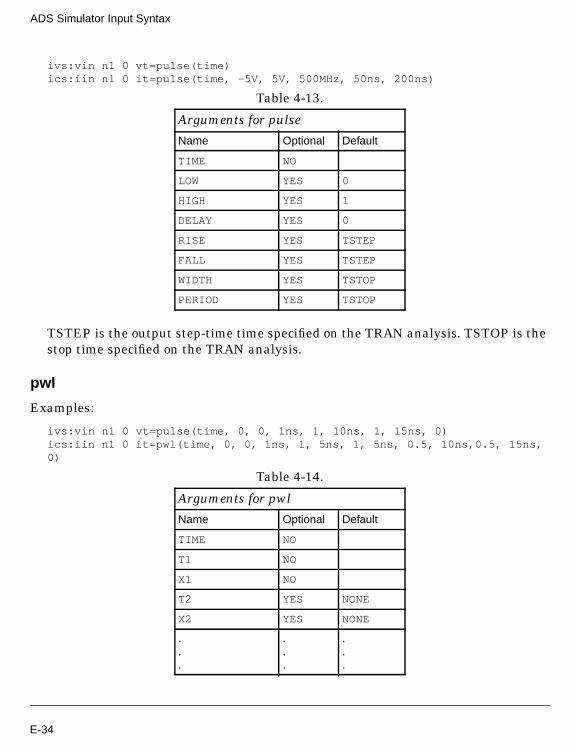
ADS Simulator Input Syntax
ivs:vin n1 0 vt=pulse(time)ics:iin n1 0 it=pulse(time, -5V, 5V, 500MHz, 50ns, 200ns)
TSTEP is the output step-time time specified on the TRAN analysis. TSTOP is thestop time specified on the TRAN analysis.
pwl
Examples:
ivs:vin n1 0 vt=pulse(time, 0, 0, 1ns, 1, 10ns, 1, 15ns, 0)ics:iin n1 0 it=pwl(time, 0, 0, 1ns, 1, 5ns, 1, 5ns, 0.5, 10ns,0.5, 15ns,0)
Table 4-13.
Arguments for pulse
Name Optional Default
TIME NO
LOW YES 0
HIGH YES 1
DELAY YES 0
RISE YES TSTEP
FALL YES TSTEP
WIDTH YES TSTOP
PERIOD YES TSTOP
Table 4-14.
Arguments for pwl
Name Optional Default
TIME NO
T1 NO
X1 NO
T2 YES NONE
X2 YES NONE
.
.
.
.
.
.
.
.
.
E-34

Conditional Expressions
The ADS Simulator supports simple in-line conditional expressions:
if boolExpr then expr else expr endif
if boolExpr then expr elseif boolExpr then expr else expr endif
boolExpr is a boolean expression, that is, an expression that evaluates to TRUE orFALSE.
expr is any non-boolean expression.
The else is required (because the conditional expression must always evaluate tosome value).
There can be any number of occurrences of elseif expr then expr.
A conditional expression can legally occur as the right-hand side of an expression orfunction definition or, if parenthesized, anywhere in an expression that a variable canoccur.
TN YES NONE
XN YES NONE
Table 4-14.
E-35

ADS Simulator Input Syntax
Boolean operators
Boolean expressions
A boolean expression must evaluate to TRUE or FALSE and, therefore, must containa relational operator (equals, =, ==, notequals, !=, <, >, <=, or >= ).
The only legal place for a boolean expression is directly after an if or an elseif .
A boolean expression cannot stand alone, that is,
x = a > b
is illegal.
Precedence
Tightest binding: equals, =, ==, notequals, !=, >, <, >=, <=
NOT, !
AND
Loosest binding: OR, ||
All arithmetic operators have tighter binding than the boolean operators.
equals logical equals
= logical equals
== logical equals
notequals logical not equals
!= logical not equals
not logical negative
! logical negative
and logical and
&& logical and
or logical or
|| logical or
< less than
> greater than
<= less than or equals
>= greater than or equals
E-36

Evaluation
Boolean expressions are short-circuit evaluated. For example, if when evaluating aand b, expression a evaluates to FALSE, expression b will not be evaluated.
During evaluation of boolean expressions with arithmetic operands, the operand withthe lower type is promoted to the type of the other operand. For example, in 3 equals
x +j*b, 3 is promoted to complex.
A complex number cannot be used with <, >, <=, or >=. Nor can an array (andremember that strings are arrays). This will cause an evaluation-time error.
Pointers can be compared only with pointers.
Examples:
Protect against divide by zero:
f(a) = if a equals 0 then 1.0e100 else 1.0/a endif
Nested if ’s #1:
f(mode) = if mode equals 0 then 1-a else f2(mode) endiff2(mode) = if mode equals 1 then log(1-a) else f3(mode) endiff3(mode) = if mode equals 2 then exp(1-a) else 0.0 endif
Nested if ’s #2:
f(mode) = if mode equals 0 then 1-a elseif mode equals 1 then log(1-a) \elseif mode equals 2 then exp(1-a) else 0.0 endif
Soft exponential:
exp_max = 1.0e16x_max = ln(exp_max)exp_soft(x) = if x<x_max then exp(x) else (x+1-x_max)*exp_max endif
VarEqn Data TypesThe four basic data types that VarEqn supports are integer, real, complex, and string.There is a fifth data type, pointer, that is also supported. Pointers are not allowed inan algebraic expression, except as an argument to a function that is expecting apointer. Strings are not allowed in algebraic expressions either except that addition ofstrings is equivalent to catenation of the strings. String catenation is notcommutative, and since VarEqn’s simplification routines can internally change the
E-37

ADS Simulator Input Syntax
order of operands of commutative operators, this feature should be used cautiously. Itwill most likely be replaced by an explicit catenation function.
Type conversion
The data type of a VarEqn expression is determined at the time the expression isevaluated and depends on the data types of the terms in the expression. For example,let y=3*x^2. If x is an integer, then y is integer-valued. If x is real, then y isreal-valued. If x is complex, then y is complex-valued.
As another example, let y=sqrt(2.5*x) . If x is a positive integer, then y evaluates to areal number. If, however, x is a negative integer, then y evaluates to a complexnumber.
There are some special cases of type conversion:
• If either operand of a division is integer-valued, it is promoted to a real beforethe division occurs. Thus, 2/3 evaluates to 0.6666....
• The built-in trigonometric, hyperbolic, and logarithmic functions never returnan integer, only a real or complex number.
‘‘C-Preprocessor’’Before being interpreted by the ADS Simulator, all input files are run through abuilt-in preprocessor based upon a C preprocessor. This brings several useful featuresto the ADS Simulator, such as the ability to define macro constants and functions, toinclude the contents of another file, and to conditionally remove statements from theinput. All C preprocessor statements begin with # as the first character.
Unfortunately, for reasons of backward compatibility, there is no way to specifyinclude directories. The standard C preprocessor ‘‘-I ’’ option is not supported;instead, ‘‘-I ’’ is used to specify a file for inclusion into the netlist.
File Inclusion
Any source line of the form
#include "filename"
E-38

is replaced by the contents of the file filename. The file must be specified with anabsolute path or must reside in either the current working directory or in/$HPEESOF_DIR/circuit/components/.
Library Inclusion
The C preprocessor automatically includes a library file if the -N command line optionis not specified and if such a file exists. The first file found in the following list isincluded as the library:
$HPEESOF_DIR/circuit/components/gemlib$EESOF_DIR/circuit/components/gemlib$GEMLIB.gemlib~/.gemlib~/gemini/gemlib
A library file is specified by the user using the -I filename command line option. Morethan one library may be specified. Specifying a library file prevents the ADSSimulator from including any of the above library files.
Macro Definitions
A macro definition has the form;
#define name replacement-text
It defines a macro substitution of the simplest kind--subsequent occurrences of thetoken name are replaced by replacement-text. The name consists of alphanumericcharacters and underscores, but must not begin with a numeric character; thereplacement text is arbitrary. Normally the replacement text is the rest of the line,but a long definition may be continued by placing a “\” at the end of each line to becontinued. Substitutions do not occur within quoted strings. Names may beundefined with
#undef name
It is also possible to define macros with parameters. For example,
#define to_celcius(t) (((t)-32)/1.8)
is a macro with the formal parameter t that is replaced with the corresponding actualparameters when invoked. Thus the line
options temp=to_celcius(77)
E-39

ADS Simulator Input Syntax
is replaced by the line
options temp=(((77)-32)/1.8)
Macro functions may have more than one parameter, but the number of formal andactual parameters must match.
Macros may also be defined using the -D command line option.
Conditional Inclusion
It is possible to conditionally discard portions of the source file. The #if line evaluatesa constant integer expression, and if the expression is non-zero, subsequent lines areretained until an #else or #endif line is found. If an #else line is found, any linesbetween it and the corresponding #endif are discarded. If the expression evaluates tozero, lines between the #if and #else are discarded, while those between the #else
and #endif are retained. The conditional inclusion statements nest to an arbitrarylevel of hierarchy. The following operators and functions can be used in the constantexpression;
The #ifdef and #ifndef lines are specialized forms of #if that test whether a name isdefined.
! Logical negation.
|| Logical or.
&& Logical and.
== Equal to.
!= Not equal to.
> Greater than.
< Less than.
>= Greater than or equal to.
<= Less than or equal to.
+ Addition.
defined(x) 1 if x defined, 0 otherwise.
E-40

WARNING: Execution of preprocessor instructions depend on the order in which theyappear on the netlist. When using preprocessor statements make sure that they arein the proper order. For example, if an #ifdef statement is used to conditionallyinclude part of a netlist, the corresponding #define statement is contained in aseparate file and #include is used to include the content of the file into the netlist, the#include statement will have to appear before the #ifdef statement for the expressionto evaluate correctly.
Data Access ComponentThe Data Access Component provides a clean, unified way to access tabular datafrom within a simulation. The data may reside in either a text file of a supported,documented format (e.g. discrete MDIF, model MDIF, Touchstone, CITIfile), or adataset. It provides a variety of access methods, including lookup by index/value, aswell as linear, cubic spline and cubic interpolation modes, with support forderivatives.
The Data Access Component provides a "handle" with which one may access datafrom either a text file or dataset for use in a simulation. The DAC is implemented asa cktlib subcircuit fragment with internally known expressions names (e.g. _DAC,_TREE) that are assigned via VarEqn calls such as read_data() andaccess_all_data() . The accessed data can be used by other components (includingmodels, devices, variables, subcircuit calls and other DAC instances) in the netlist,either by the specific file syntax or via the VarEqn function dep_data() .
The DAC can also be used to supply parameters to device and model componentsfrom text files and datasets. In this case, the AllParams device/model parameter isused to refer to a DAC component. The component’s parameters will then be accessedfrom the DAC and supplied to the instance. Care is taken to ensure that onlymatching (between parameter names in the component definition and DACdependent column names) data is used. Also, parameter data can be assigned "inline"- as is usually done - in which case the inline data takes precedence over the DACdata.
As the DAC component is composed of just a parameterized subcircuit, it allowsalterations (sweep, tune, optimize, yield) of its parameters. Consequently anycomponent that uses DAC data via file, dep_data() or AllParams will automatically beupdated when a DAC parameter is altered. A caveat with sweeping over files using
E-41

ADS Simulator Input Syntax
AllParams is that all the files must contain the same number of dependent columns ofdata.
Below is an example definition of a simple DAC component that accesses discretevalues from a text file:
#uselib "ckt" , "DAC"DAC:DAC1 File="C:\jeffm\ADS_testing\ADS13_test_prj/.\data\SweptData.ds"Type="dataset" Block="S" InterpMode="linear" InterpDom="ri" iVar1="X"iVal1=X iVar2="freq" iVal2=freqS_Port:S2P1 _net1 0 _net6 0 S[1,1]=file{DAC1, "S[1,1]"}S[1,2]=file{DAC1,"S[1,2]"} S[2,1]=1 S[2,2]=0 Recip=no
dindex = 1DAC:atc1 File="vdcr.mdf" Type="dscr" \InterpMode="index_lookup" iVar1=1 iVal1=dindex
And its use to provide the resistance value to a pair of circuit components:
R:R1 n1 0 R=file{atc1, "R"} kOhmR:R2 n1 0 R=dep_data(atc1, "R") kOhmHere, it provides the value to a variable:V1 = file{atc1, "Vdc"}
V1 could be used elsewhere in the circuit, as expected.
In this example, a scaling factor applied to the result of a DAC access is shown:
File = "atc.mdf"Type = "dscr"Mode="index_lookup"Cnom = "Cnom"DAC:atc_s File=File Type=Type InterpMode=Mode iVar1=1 iVal1 = Cs_rowC:Cs n1 n2 C=file{atc_s, Cnom} Pf
In this example, a use of AllParams is shown to enter model parameters from a textfile:
File = "c:\gemini\vdcr.mdf"Type = "dscr"Mode="index_lookup"DAC:dac1 File=File Type=Type InterpMode=Mode iVar1=1 iVal1 = ixmodel rm1 R_Model R=0 AllParams = dac1._DACrm1:rm1i1 n3 0
E-42

Reserved WordsThe words on the following pages have built-in meaning and should not be defined orused in a way not consistent with their pre-defined meaning. They are listed inalphabetical order for convenience.
“A”onpage-44
“B”onpage-44
“C”onpage-44
“D”onpage-45
“E”onpage-45
“F”onpage-45
“G”onpage-46
“H”onpage-46
“I”onpage-46
“J”onpage-46
“K”onpage-46
“L”onpage-46
“M”onpage-46
“N”onpage-48
“O”onpage-49
“P”onpage-49
“Q”onpage-50
“R”onpage-50
“S”onpage-50
“T”onpage-52
“U”onpage-52
“V”onpage-53
“W”onpage-53
“X”onpage-53
“Y”onpage-53
“Z”onpage-53
“a”onpage-57
“b”onpage-57
“c”onpage-57
“d”onpage-58
“e”onpage-58
“f”onpage-59
“g”onpage-59
“h”onpage-59
“i”onpage-59
“j”onpage-60
“k”onpage-60
“l”onpage-60
“m”onpage-61
“n”onpage-61
“o”onpage-61
“p”onpage-61
“q”onpage-62
“r”onpage-62
“s”onpage-62
“t”onpage-63
“u”onpage-63
“v”onpage-63
“w”onpage-64
“x”onpage-64
“y”onpage-64
“z”onpage-64
“__”onpage-53
“_”onpage-53
E-43

ADS Simulator Input Syntax
A
ACACPWDS ACPWDTLAIRIND1AlterAmplifierAmplifierP2DAntLoad
B
BFINLBFINLTBJTBR3CTLBR4CTLBRCTLBROCTLBesselBudLinearizationButterworth
C
CCAPP2CAPQCIND2CLINCLINPCOAXCOAXTLCPWCPWCGAPCPWCPL2CPWCPL4CPWCTLCPWDSCPWEFCPWEGAP
E-44

CPWGCPWOCCPWSCCPWSUBCPWTLCPWTLFGCTLC_ModelChainChebyshevConnectorCostIndexCrossover
D
DCDFDFDevice1DFDevice2DF_DefaultIntDF_ValueDF_ZERO_OHMSDICAPDILABMLCDOEDRCDefaultValueDeviceIndexDiode
E
EE_BJT2EE_FET3EE_HEMT1EE_MOS1ETAPERElliptic
F
E-45

ADS Simulator Input Syntax
FDDFINLINEFSUB
G
GCPWTLGMSK_LowpassGaAsGaussianGoal
H
HBHP_DiodeHP_FETHP_FET2HP_MOSFETHybrid
I
IFINLIFINLTINDQI_SourceInitCondInoiseBD
J
JFET
K
L
LLineCalcTest
M
MACLINMACLIN3MBEND
E-46

MBEND2MBEND3MBSTUBMCFILMCLINMCORNMCROSMCROSOMCURVEMCUREVE2MGAPMICAP1MICAP2MICAP3MICAP4MLANGMLANG6MLANG8MLEFMLINMLOCMLSCMLYRSUBMOS9MOSFETMRINDMRINDELAMRINDELMMRINDNBRMRINDWNRMRSTUBMS2CTLMS3CTLMS4CTLMS5CTLMSABNDMSACTLMSAGAPMSBEND
E-47

ADS Simulator Input Syntax
MSCRNRMSCROSSMSCTLMSGAPMSIDCMSIDCFMSLANGEMSLITMSOBNDMSOCMSOPMSRBNDMSRTLMSSLITMSSPLCMSSPLRMSSPLSMSSTEPMSSVIAMSTAPERMSTEEMSTEPMSTLMSUBMSVIAMSWRAPMTAPERMTEEMTEEOMTFCMextramBJTMixerMixerIMTMultipathMutual
N
NodeSetNoiseCorr2Port
E-48
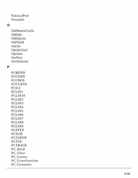
Noisey2PortNsample
O
OldMonteCarloOldOptOldOptimOldYieldOptimOptimGoalOptionsOscPortOutSelector
P
PCBENDPCCORNPCCROSPCCURVEPCILCPCLIN1PCLIN10PCLIN2PCLIN3PCLIN4PCLIN5PCLIN6PCLIN7PCLIN8PCLIN9PCSTEPPCSUBPCTAPERPCTEEPCTRACEPC_BendPC_ClearPC_CornerPC_CrossJunctionPC_Crossover
E-49

ADS Simulator Input Syntax
PC_GapPC_LinePC_OpenStubPC_PadPC_SlantedPC_TaperPC_TeePC_ViaPINPIN2PLCQParamSweepPinDiodePoleZeroPolynomialPortPowerBouncePowerGroundPlane
Q
R
RRCLINRIBBONRIBBON_MDSRINDRWGRWGINDFRWGTRWGTLR_ModelRaisedCos
S
SAGELINSAGEPACSBCLINSBENDSBEND2
E-50
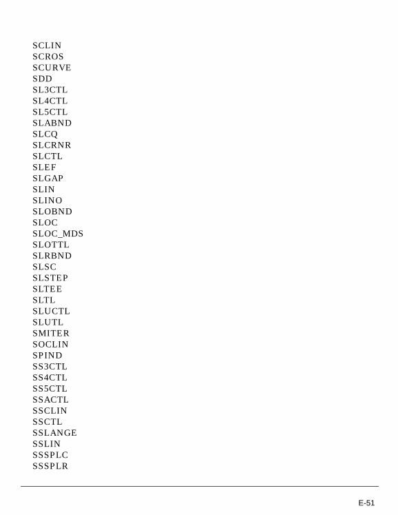
SCLINSCROSSCURVESDDSL3CTLSL4CTLSL5CTLSLABNDSLCQSLCRNRSLCTLSLEFSLGAPSLINSLINOSLOBNDSLOCSLOC_MDSSLOTTLSLRBNDSLSCSLSTEPSLTEESLTLSLUCTLSLUTLSMITERSOCLINSPINDSS3CTLSS4CTLSS5CTLSSACTLSSCLINSSCTLSSLANGESSLINSSSPLCSSSPLR
E-51

ADS Simulator Input Syntax
SSSPLSSSSUBSSTEPSSTFRSSTLSSUBSSUBOS_ParamS_PortScheduleCycleShortSubstrateSweepPlanSwitchVSwitchV_Model
T
TAPIND1TFCTFC_MDSTFRTFR_MDSTLTLINTLIN4TLINPTLINP4TL_NewTQAVIATQCAPTQFETTQFET2TQINDTQRESTQSVIATQSWHTQTLTran
U
E-52

UFINLUFINLTUnalter
V
VBICVIAVIA2V_SourceVnoiseBD
W
WIREWIRE_MDS
X
Y
Y_PortYieldYieldOptimYieldSpecYieldSpecOld
Z
Z_Port
__
__fdd__fdd_v
_
_ac_state_c1_c10_c11_c12_c13_c14_c15
E-53

ADS Simulator Input Syntax
_c16_c17_c18_c19_c2_c20_c21_c22_c23_c24_c25_c26_c27_c28_c29_c30_c4_c5_c6_c7_c8_c9_dc_state_default_discrete_density_divn_freq1_freq10_freq11_freq12_freq2_freq3_freq4_freq5_freq6_freq7_freq8_freq9_gaussian
E-54

_gaussian_tol_get_fnom_freq_get_fund_freq_for_fdd_harm_hb_state_i1_i10_i11_i12_i13_i14_i15_i16_i17_i18_i19_i2_i20_i21_i22_i23_i24_i25_i26_i27_i28_i29_i3_i30_i4_i5_i6_i7_i8_i9_lfsr_mvgaussian_mvgaussian_cov_n_state
E-55

ADS Simulator Input Syntax
_nfmin_p2dInputPower_phase_freq_pwl_density_pwl_distribution_randvar_rn_shift_reg_si_si_bb_si_d_si_e_sigproc_state_sm_state_sopt_sp_state_sv_sv_bb_sv_d_sv_e_tn_to_tr_state_tt_uniform_uniform_tol_v1_v10_v11_v12_v13_v14_v15_v16_v17_v18_v19_v2_v20
E-56

_v21_v22_v23_v24_v25_v26_v27_v28_v29_v3_v30_v4_v5_v6_v7_v8_v9_xcross
a
absaccess_all_dataaccess_dataaeleandarcsinharctanatan2awg_dia
b
binbitseqboltzmannby
c
c0complexconj
E-57

ADS Simulator Input Syntax
coscos_pulsecoshcotcothcouplingctofctokcxform
d
d_atan2damped_sindbdbmdbmtoadbmtovdbmtowdbpolardbwtowdcSourceLeveldeembeddefinedegdelaydep_dataderivdiscretedistcompnamedoedoeindexdphasedsexprdstoarray
e
ee0echoelse
E-58

elseifendendifequalserf_pulseeval_polyexpexp_pulse
f
filefreadfreqfreq_mult_coeffreq_mult_polyftocftok
g
gaussgaussiangenerate_gmsk_iq_spectragenerate_gmsk_pulse_spectragenerate_piqpsk_spectragenerate_pulse_train_spectragenerate_qam16_spectragenerate_qpsk_pulse_spectraget_array_sizeget_attributeget_blockget_fund_freqget_max_pointsglobalglobalnodeground
h
hugereal
i
E-59

ADS Simulator Input Syntax
iifilsbimagindexinnerprodinoiseintinternal_generate_gmsk_iq_spectrainternal_generate_gmsk_pulse_spectrainternal_generate_piqpsk_spectrainternal_generate_pulse_train_spectrainternal_generate_qam16_spectrainternal_generate_qpsk_pulse_spectrainternal_get_fund_freqinternal_windowinterpinterp1interp2interp3interp4issitobiusb
j
jn
k
ktocktof
l
lbtranlengthlimit_warnlistlnln10local
E-60

loglogNodesetScalelogRshuntlog_amplog_amp_cas
m
magmakearraymaxmcTrialmcindexminmodelmulti_freq
n
namesnestednfnfminnonodoenoisefreqnooptnormnostatnotnotequals
o
omegaoptoptIteror
p
parametersphasephase_noise_pwl
E-61

ADS Simulator Input Syntax
phasedegphaseradplanckpolarpolarcpxpptpulsepwlpwlr
q
qelectronqinterp
r
radramprandtimerawtoarrayread_dataread_libreaddatareadlibreadrawrealrectremripplermsrnrpsmooth
s
scalearraysenssetDTsffmsgnsinsinc
E-62

sinesinhsinksoptsourceLevelsprintfsqrtssfreqstatstepstrcatstypexformsym_setsystem
t
tantanhtemptempkelvinthdthentimetimesteptinyrealtotoitranordertransform
u
u0unconstunicapuniform
v
vvaluevlsb
E-63

ADS Simulator Input Syntax
vnoisevssvswrpolarvusb
w
window
x
y
yes
z
E-64

Index
AADS Simulator, 2-1help, 2-2output
instance parameters, 2-2instance statement, 2-2model parameters, 2-3model statement, 2-3
ArtistUtilities, 1-3attribute definitions
boolean, 2-5character string, 2-6complex number, 2-5device instance, 2-6integer, 2-5modifiable, 2-5optimizable, 2-5readable, 2-5real number, 2-5required, 2-5settable, 2-5
Ccommands
cdfDump, 3-5, 3-8cdfDumpAll, B-1hpeesofsim, 2-1
component description formatcdfDumpAll, B-1editing the cdf, 3-5, 3-6instance parameters, 4-2loading the cdf, 3-16modifying the cdf, 3-4new simulator, B-3outputting the cdf, 3-5simulation information, 3-5, 3-6tool filter, B-3
Ddirectories
scripts, D-3simulator, D-1symbolic links, D-1
Eediting
cdf, 3-5, 3-6environment, 2-1expressions
instance parameters, 4-6model parameters, 4-3, 4-6VarEqn block, 4-3
Ffiles
simInfo.il, D-1formatting
model, 2-1netlist, 2-1
functionsalmBuildLibrary, D-2netlisting
IdfCompPrim, 3-16IdfDevPrim, 3-16
GgeminiInclude, 4-4
Iinstance parameters, 2-2instance statement, 2-2
Llibraries
analogLib, 1-1, 1-2, D-1basic, 1-1, C-1modifying, C-1, D-1nlpglobals, C-1
Mmodel files
capitalization, 4-1continuation character, 4-1creating, 4-1default parameter value, 4-1model parameters, 4-3subnetworks, 4-2syntax, 4-1
model formatting, 2-1
Index-1

model parameters, 2-3attribute definitions, 2-5expressions, 4-3, 4-6model file, 4-3
model statement, 2-3modifying
cdf, 3-4netlisting functions, 3-16
Nnetlist
formatting, 2-1netlist include component
geminiInclude, 4-4netlisting functions
IdfCompPrim, 3-16IdfDevPrim, 3-16modifying, 3-16
Sscripts
analogLib, D-2directories, D-3
shell variables, 1-2simulation information, 3-5, 3-7, 3-8
additional notes, 3-15componentName, 3-9instParameters, 3-9macroArguments, 3-9modelArguments, 3-9namePrefix, 3-12netlistProcedure, 3-8otherParameters, 3-8propMapping, 3-12termMapping, 3-9termOrder, 3-9typeMapping, 3-12unused fields, 3-12
simulator directories, D-1
VVarEqn, 4-3viewing
simulation information, 3-7, 3-8views
ads, 3-1, C-1ads symbol, 3-1stop view, 3-1
Index-2