ifi jaguar datasheet
TRANSCRIPT

8/13/2019 IFI JAGUAR Datasheet
http://slidepdf.com/reader/full/ifi-jaguar-datasheet 1/15Jaguar Motor Controller (217-3367) 1
B O A R D D A T A S H E E T
General DescriptionThe Jaguar motor control module is a variable speed control for 12 V and 24 V brushed DC motors at up to40 A continuous current. The motor control module includes high performance CAN networking as well as arich set of control options and sensor interfaces, including analog and quadrature encoder interfaces.
The high-frequency pulse width modulator (PWM) enables the DC motor to run smoothly and quietly over awide speed range. The Jaguar uses highly optimized software and a powerful 32-bit Stellaris microcontrollerto implement open-loop speed control as well as closed-loop control of speed, position, or motor current.
Jaguar Motor Controller (Stellaris® BrushedDC Motor Control Module with CAN) 217-3367
ProductNumber
Description
217-3367 Stellaris® Brushed DC Motor ControlModule with CAN (217-3367) for Single-UnitPackaging
Ordering Information
ContentsGeneral Description ......................... 1 Overview ....................................... 2 Detailed Features .......................... 2Operational Speci cations .............. 4 Servo-style PWM Input ................. 7 Electrical Interface ......................... 7 Power Supply ................................ 8 Motor Selection ............................. 8 Operating Modes ........................... 8 Default Parameters ........................9 Wiring ............................................ 9 Mechanical Details ...................... 10 Status LED .................................. 11 Jumper Settings .......................... 11 Fault Detection ............................ 12 Calibration ................................... 12 CAN Communication ................... 12 Coast/Brake Input ....................... 13 Analog Input ................................ 14 Encoder Input .............................. 14 Limit Switch Inputs ...................... 15 Firmware Update ......................... 15
Additional Information ................... 15
Figure 1. Brushed DC Motor ControlModule
Figure 2. Mechanical Drawing
1212

8/13/2019 IFI JAGUAR Datasheet
http://slidepdf.com/reader/full/ifi-jaguar-datasheet 2/15
Jaguar Motor Controller (217-3367) 2
B O A R D D A T A S H E E T
Figure 3. Jaguar Motor Controller
OverviewThe Jaguar motor control board provides the following features:• Controls brushed 12 V and 24 V DC motors up to 40 A continuous• Controller Area Network (CAN) interface at 1 Mbit/s• Industry-standard servo (PWM) speed input interface• RS232 to CAN bridge• Limit switch, encoder, and analog inputs• Fully enclosed module includes cooling fan
• Flexible con guration options with simple source le modi cation• Easy to customize—full source code and design les available
Detailed FeaturesThis section describes the Jaguar’s features in detail:• Quiet control of brushed DC motors
– 15 kHz PWM frequency• Three options for Speed control
– Industry-standard R-C servo type (PWM) interface – Controller Area Network (CAN) interface – RS232 serial interface
• CAN communication – Multicast shared serial bus for connecting systems in electromagnetically noisy environments – 1M bits/s bit rate – CAN protocol version 2.0 A/B – Full con gurability of module options – Real-time monitoring of current, voltage, speed, and other parameters – Firmware update
• RS232 serial communication – Bridges RS232 port to a CAN network – Directly interfaces to a PC serial port or National Instruments cRIO
• Automatic Output Ramp mode

8/13/2019 IFI JAGUAR Datasheet
http://slidepdf.com/reader/full/ifi-jaguar-datasheet 3/15
Jaguar Motor Controller (217-3367) 3
B O A R D D A T A S H E E T
• Status LED indicates Run, Direction, and Fault conditions• Motor brake/coast selector • Limit switch inputs for forward and reverse directions• Quadrature encoder input (QEI)
– Index input – 5 V supply output to encoder
• Analog input – Accepts 10 k potentiometer or 0-3 V input
• Screw terminals for all power wiring• Headers (0.1 inch pitch) for all control signals
Figure 4. Detailed Drawing of the Jaguar Motor Control Module

8/13/2019 IFI JAGUAR Datasheet
http://slidepdf.com/reader/full/ifi-jaguar-datasheet 4/15
Jaguar Motor Controller (217-3367) 4
B O A R D D A T A S H E E T
Operational Speci cationsThe following tables provide the operation speci cations for the Jaguar motor control board.
WARNING – Do not exceed the maximum supply voltage of 30 V DC .
Doing so will cause permanent damage to the module.
Table 1. Power Supply
Table 2. Motor Output
Table 3. Environment
Parameter Min Typ Max UnitsSupply voltage range (V IN) 5.5 a 12/24 30 Vdc
Supply voltage absolute maximum – – 35 b Vdc
Supply current (motor off, fan off) (V IN = 12 V) – 35 – mA
Supply current (motor off, fan on) (V IN = 12 V) – 105 – mA
Under-voltage detect threshold – 6.0 – Vdc
a. Power supply requires V IN ≥ 7.0 V DC to start up.b. Exceeding this limit, even momentarily, will cause permanent damage.
Parameter Min Typ Max UnitsMotor voltage a 0 – V IN V
Motor current - continuous – – 40 A
Motor current – for 2 seconds – – 60 A
Motor current – peak at starting – – 100 A
PWM frequency – 15.625 – kHz
PWM resolution – 0.1 – %
Output current for resistive loads b – – 30 A
a. The motor voltage is controlled by using a pulse-width modulated waveform.b. The output current for resistive loads is continuous and the value shown is the maximum value.
Parameter Min Typ Max UnitsOperating temperature range 0 – 50 °C
Storage temperature range -25 – 85 °C
Fan on temperature – 42 – °CFan off temperature – 38 – °C

8/13/2019 IFI JAGUAR Datasheet
http://slidepdf.com/reader/full/ifi-jaguar-datasheet 5/15
Jaguar Motor Controller (217-3367) 5
B O A R D D A T A S H E E T
Table 4. Servo-Style Speed Input
Parameter Min Typ Max UnitsMinimum pulse width a,b 0 0.67 ms
Neutral pulse widthb
– 1.5 – msMaximum pulse width b,c – 2.33 – ms
Servo signal period 5.0125 – 29.985 ms
Valid pulse width range 0.5 – 2.50625 ms
Duty cycle range – – 50 %
Digital high-level input current 2 5 25 mA
Digital low-level input current – – 0.3 mA
Watchdog time-out – 100 – ms
Voltage isolation (servo+/- to other signals) d – – 40 V
a. Sets full-speed in reverse.b. These are the default values. Pulse-width range can be calibrated for different values. See the servo PWM
calibration procedure on page 12.c. Sets full-speed in forward direction.d. The servo input is optically isolated.
Table 5. Analog Input
Table 6. Voltage, Current, and Temperature Measurement
Parameter Min Typ Max Units Analog input voltage 0 – 3 V
Potentiometer value – 10 – kΩ
Potentiometer reference voltage (+ pin) a 2.9 3.0 3.1 V
Measurement resolution – 10-bit – bits
Measurement rate – 15.625 – kHz
a. With 10 kΩ potentiometer connected.
Parameter Min Typ Max UnitsTemperature measurement accuracy – +/- 6 – °C
Supply voltage measurement accuracy – +/- 0.3 – V
Motor current measurement accuracy ≥ 8A – +/- 1 – A
Motor current measurement accuracy < 8A – +/- 2 – A
Measurement resolution – 10 – bits
Measurement rate – 15.625 – kHz

8/13/2019 IFI JAGUAR Datasheet
http://slidepdf.com/reader/full/ifi-jaguar-datasheet 6/15
Jaguar Motor Controller (217-3367) 6
B O A R D D A T A S H E E T
Table 7. Brake/Coast Input
Table 8. Quadrature Encoder Input (QEI)
Table 9. CAN Interface
Parameter Min Typ Max UnitsDigital low-level input voltage a -0.3 – 1.3 V
Digital high-level input voltage b 2.0 3.3 5.0 V
Digital input pull-down resistor – 200 – kΩ
Response time – 64 – μs
Power on Pin 1 (3.3 V) – – 25 mA
a. Selects Brake mode.b. Selects Coast mode.
Parameter Min Typ Max UnitsDigital low-level input voltage a -0.3 – 1.3 V
Digital high-level input voltagea
2.0 3.3 5.0 VDigital input pull-down resistor – 10 – kΩ
Encoder rate b DC – 1 M
Encoder supply voltage 4.90 5.0 5.10 V
Encoder supply current – – 100 mA
a. Applies to A, B, and Index inputs.b. Measured in transitions per second.
Parameter Min Typ Max UnitsBit rate 0.0133a 1 1 Mbps
Recommended bus termination b – 100 – Ω
Absolute maximum CANH, CANL voltage -27 – 40 V
Watchdog time-out – 100 – ms
Number of nodes per network c (protocol limit) 1 – 63 #
Number of nodes per network (physical limit) 1 – 16 #
Total cable length – – 2.06.1
ftm
a. Limited by fail-safe CAN transceiver SN65HVD1050.b. Two terminations per network.c. Must be a valid ID range.
8/13/2019 IFI JAGUAR Datasheet
http://slidepdf.com/reader/full/ifi-jaguar-datasheet 7/15
Jaguar Motor Controller (217-3367) 7
B O A R D D A T A S H E E T
Table 10. RS232 Interface
Parameter Min Typ Max UnitsBaud rate – 115,200 – Baud
Format – 8, n, 1 –
Watchdog time-out – 100 – ms
RXD Absolute Maximum Voltage Range -25 – +25 V
TXD High-level output voltage 5 5.4 – V
TXD Low-level output voltage -5 -5.4 – V
RXD Positive-going threshold – 1.9 – V
RXD Negative-going threshold – 1.4 – V
Table 11. Limit Switch Interface
Parameter Min Typ Max UnitsDigital low-level input voltage a -0.3 – 1.36 V
Digital high-level input voltage b 2.0 3.3 5.0 V
Pull-up resistor – 10 – kΩ
Response time – 64 – μs
a. Motor enabled state.b. Motor disabled state.
Servo-style PWM InputThe Jaguar incorporates support for speed and direction control using the standard servo-style interface found
on many radio-control receivers and robot controllers. See the electrical speci cations for default timing of thissignal.
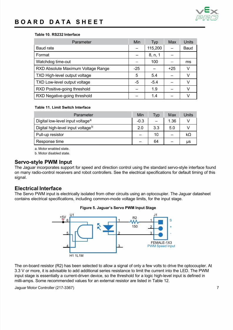
Electrical InterfaceThe Servo PWM input is electrically isolated from other circuits using an optocoupler. The Jaguar datasheetcontains electrical speci cations, including common-mode voltage limits, for the input stage.
Figure 5. Jaguar’s Servo PWM Input Stage
The on-board resistor (R2) has been selected to allow a signal of only a few volts to drive the optocoupler. At3.3 V or more, it is advisable to add additional series resistance to limit the current into the LED. The PWMinput stage is essentially a current-driven device, so the threshold for a logic high-level input is de ned inmilli-amps. Some recommended values for an external resistor are listed in Table 12.
+5V6 1 1
J1R2
150
U1
H1 1L1M
FEMALE-1X3PWM Speed Input
S
5 2
2 +
4 3
3 -

8/13/2019 IFI JAGUAR Datasheet
http://slidepdf.com/reader/full/ifi-jaguar-datasheet 8/15
Jaguar Motor Controller (217-3367) 8
B O A R D D A T A S H E E T
Table 12. Recommended External Resistor Values
PWM Signal Level External Series Resistor Value2.5 V 0Ω (none)
3.0 V 0Ω - 150Ω
5.0 V 560Ω
12 V 2.2kΩ
Power SupplyThe Jaguar is designed primarily for use with 12 V or 24 V sealed lead-acid batteries, although other powersources can be used as long as the voltage range is not exceeded. See the Brushed DC Motor ControlReference Design Kit (RDK) User’s Manual for more detail.
NOTE: The Jaguar does not have reverse polarity input protection.
Motor SelectionThe Jaguar operates 12 V or 24 V brushed DC motors. Typical motors include the BI802-001A model fromCIM and the RS-555PH-3255 model from Mabuchi. Some very small DC motors or motors in lightly loadedapplications may have a limited useful speed range.
The Jaguar can also drive resistive loads with some de-rating to allow for increased ripple current inside themodule.
Operating ModesThe Jaguar can be controlled using either the servo-style PWM input or the CAN interface. Table 13 comparesthe capabilities of the two control methods.
Table 13. Comparison of Control Methods
Control MethodServo-Style PWM Input CAN Interface
Speed Control Yes Yes
Analog Position Control No Yes
Encoder Position Control No Yes
Con gurable Parameters No Yes
Voltage, Current Measurement No Yes
Limit Switches Yes Yes
Coast/Brake Feature Yes Yes
Firmware Update No Yes
The Jaguar does support the simultaneous use of CAN for monitoring and the servo-style input for speed.
NOTE: See the Jaguar Getting Started Guide for additional calibration information.

8/13/2019 IFI JAGUAR Datasheet
http://slidepdf.com/reader/full/ifi-jaguar-datasheet 9/15
Jaguar Motor Controller (217-3367) 9
B O A R D D A T A S H E E T
Default ParametersTable 14 lists the default con guration of the Jaguar. Parameters can be modi ed using CAN commands orby modifying the software source code. Parameters changed using CAN commands are volatile and must bereloaded if power is cycled.
Table 14. Default Factory Con gurationParameter Default Value
Acceleration rate Instantaneous change
Deceleration rate Instantaneous change
Motor Control mode Open-loop speed control using voltage
WiringThe Jaguar is controlled using either a servo-type PWM source, CAN bus, or RS232 interface. Figure 6 showsa typical, simple wiring arrangement with power, motor, PWM control, and optional limit-switch connections.Basic servo-style PWM control is enabled by default and does not require CAN con guration.
Figure 7 on page 10 shows an advanced wiring con guration using the CAN interface. Wiring for positionsensing using both a position potentiometer and a quadrature encoder is detailed. Although two sensor typesare shown, the Jaguar software supports control and monitoring of only one sensor at a time.
Figure 6. Basic Wiring with a Servo-Style Speed Command

8/13/2019 IFI JAGUAR Datasheet
http://slidepdf.com/reader/full/ifi-jaguar-datasheet 10/15
Jaguar Motor Controller (217-3367) 10
B O A R D D A T A S H E E T
Figure 7. Basic RS232/CAN-Based Control Wiring Diagram
Figure 8. Mechanical Drawing
Mechanical DetailsFigure 8 shows the Jaguar physical dimensions. The module has two 0.175” (4.5 mm) diameter mountingholes as shown in Figure 8.
The Jaguar should be mounted so that the vents in the top and sides of the module are not restricted in anyway. A clearance of ½ inch should be maintained around the module.

8/13/2019 IFI JAGUAR Datasheet
http://slidepdf.com/reader/full/ifi-jaguar-datasheet 11/15
Jaguar Motor Controller (217-3367) 11
B O A R D D A T A S H E E T
Status LEDTable 15 lists all of the LED status and fault codes for Normal Operating, Fault, and Calibration or CANconditions. Fault information is prioritized, so only the highest priority fault will be indicated.
Table 15. Normal Operating Conditions
LED State Module StatusNormal Operating Conditions
Solid Yellow Neutral (speed set to 0)
Fast Flashing Green Forward
Fast Flashing Red Reverse
Solid Green Full-speed forward
Solid Red Full-speed reverse
Fault Conditions
Slow Flashing Yellow Loss of servo or Network linkFast Flashing Yellow Invalid CAN ID
Slow Flashing Red Voltage, Temperature, or Limit Switch fault condition
Slow Flashing Red and Yellow Current fault condition
Calibration or CAN Conditions
Flashing Red and Green Calibration mode active
Flashing Red and Yellow Calibration mode failure
Flashing Green and Yellow Calibration mode success
Slow Flashing Green CAN ID assignment mode
Fast Flashing Yellow Current CAN ID (count ashes to determine ID)
Flashing Yellow CAN ID invalid (that is, Set to 0) awaiting valid ID assignment
Jumper SettingsFigure 9 shows the factory-default jumper settings.
Figure 9. Default Factory Jumper Settings

8/13/2019 IFI JAGUAR Datasheet
http://slidepdf.com/reader/full/ifi-jaguar-datasheet 12/15
Jaguar Motor Controller (217-3367) 12
B O A R D D A T A S H E E T
Fault DetectionThe Jaguar detects and shuts down the motor if any of the following conditions are detected:* Power supply under-voltage* Over temperature* Over current* Loss of CAN/RS232 or servo-style speed link* Limit switch activated in the current direction of motionThe LED indicates a fault state during the fault condition and for three seconds after the fault is cleared (exceptfor the limit switch and link faults, which are instantaneous).
CalibrationTo accommodate variation in the timing of the supplied signal, the Jaguar has a calibrate feature that sets newvalues for full-forward, full-reverse, and points in between.
Follow these steps to initiate calibration:
1. Hold down the user switch for ve seconds.2. Set the controller to send a full-forward signal.3. Set the controller to send a full-reverse signal.4. Set the controller to send a neutral signal.
The Jaguar samples these signals and centers the speed range and neutral position between these limits.See the Jaguar Getting Started Guide for complete calibration procedure information.
CAN CommunicationThe Controller Area Network (CAN) provides a powerful interface for controlling one or more Jaguaror MDL-BDC modules.
ProtocolThe CAN protocol used by the Jaguar includes the following capabilities:
• Firmware update over CAN• Read supply voltage, motor voltage, temperature, and current• Set motor voltage or target position• Set control mode to speed or position
Each Jaguar module on the CAN bus is accessed using an assigned ID number. The ID number defaults to 1,but can be changed by sending a CAN assign ID command to the bus.

8/13/2019 IFI JAGUAR Datasheet
http://slidepdf.com/reader/full/ifi-jaguar-datasheet 13/15

8/13/2019 IFI JAGUAR Datasheet
http://slidepdf.com/reader/full/ifi-jaguar-datasheet 14/15
8/13/2019 IFI JAGUAR Datasheet
http://slidepdf.com/reader/full/ifi-jaguar-datasheet 15/15
B O A R D D A T A S H E E T
Limit Switch InputsTwo limit switch inputs provide a method for immediate shut-down of the motor. The inputs expect typically-closed contacts - one for each direction of rotation. See Table 11 on page 7 for electrical speci cations.
Firmware UpdateThe Jaguar rmware can be updated over CAN and RS232. The capability to update the Jaguar rmware canbe added to most Host controllers by implementing the necessary protocol. If you are not developing a CANhost controller, the BDC-COMM application provides rmware update from a Windows PC.
For additional information on the rmware update procedure, see the Jaguar Getting Started Guide ,
Additional InformationThe following documents are available for download at www.vexrobotics.com/vexpro• Jaguar Getting Started Guide• BDC·COMM User’s Guide
- Schematics and 811-of-Matcria.Js (BOM)- Detailed functional description- Firmware update, con guration, and operation