ifr for professional pilots
DESCRIPTION
PDF book "IFR for Professional Pilots"TRANSCRIPT
IFR for Professional Pilots
2009 Canadian Instrument Rating procedures. Expands on procedures and requirements in AIM and Instrument Procedures Manual
Selkirk College IFR Manual
IFR for Professional Pilots
2
2008
Needed amendments:
The following items are in need of amendment in this text but time has not yet permitted
this work. If you have other suggestions please let me know.
Jeppesen approach plates – briefing strip
Sample cold temperature correction problems with answers.
IFR for Professional Pilots
3
Selair.selkirk.ca
Introduction To be a Professional Pilot is more or less synonymous with being an IFR pilot. It should
therefore be clear that the contents of this text are vital to anyone who wishes to be a
professional pilot. I would not want to leave you with the impression that it contains all
that is important however. This text concentrates on the technicalities of IFR flying, but
only a limited discussion of the decision making that is required can be presented here. In
addition the supporting topics of meteorology and air regulations are left for other texts
and courses. There is a rich philosophical subtext to professional aviation that cannot be
put into words. There is a professional mindset that you must dedicate yourself to
developing. Technical competence alone is not enough.
In this course you will learn the procedural aspects of IFR flight, that is to say how holds,
approaches, STARs, SIDS and the many other procedures are conducted. You will also
develop a sense of how the ATC system supports you, the Professional Pilot. You will
learn the communication techniques that are so vital to safe IFR flight. And, you will
learn to “think like an IFR pilot,” by which we mean, to deploy the various pieces of
equipment at your disposal to keep track of your position in the abstract world you have
chosen to devote your life to. This course coordinates with Avia 120 and 220 in which
you learn meteorology, Avia 130 and 230 in which you learn all the relevant regulations,
Avia 150 and 250 in which you develop the teamwork skills so vital to your success,
Avia 240 in which you learn the additional details of long range flight, and Avia 261 in
which you learn the technicalities of all the navigation systems. Only when the complete
package has been synthesized in your mind will you be ready to call yourself a
Professional Pilot. Keep in mind that synthesis is necessary. Avoid the tendency to take
the new knowledge in as discreet bits. All the techniques, skills, and knowledge are
useless if isolated.
This course follows Avia 160 in which you learned the fundamentals of navigation, and
developed a rudimentary appreciation of how the IFR system works. There will be review
questions and assignments in this course. Be sure to keep your Navigation for
Professional Pilots text and review it often during this course.
In Canada NavCanada is responsible for maintaining the navigation infrastructure of our
airspace system. Their mandate includes installing and maintaining the hundreds of
VORs, NDBs, and ILSs. You will learn more about NavCanada in Avia 230. The US
military operates a GPS satellite system that pilots from all countries are permitted to use
(with limitations that you need to be aware of.) The Russians have a separate GPS
system, and the Europeans are preparing to launch their own. As all these technical
wonders of the 21st century are the structure of the environment you will work in you
should develop a keen interest in how they all work. The course Avia 261 covers most of
this, but you must develop the habit of keeping abreast of future changes post-graduation.
How navigation systems work is largely beyond the scope of this course, but we will
spend a lot of time examining the work-a-day details of employing them; the difference
being roughly the equivalent of knowing how to drive a car as opposed to how it works.
We will examine what navaids should be used as well as when, and how to do this
IFR for Professional Pilots
4
2008
without losing situational awareness. You will discover that flying IFR is inherently
abstract. By far the biggest challenge both initially and throughout your career will be
“situational awareness.” Many accidents are the result of controlled flight into terrain
(CFIT) which happens when the pilot looses the mental image of where s/he is. Aspects
of countering this are raised in Avia 150 and 250, but the recommended procedures
developed in this course are designed to help you avoid this fate.
Throughout this course you will need the Transport Canada Instrument Procedures
Manual, a CAP2, CAP3, LO1/2, HI, Terminal Charts, and CFS. Also, have your CR and
an electronic calculator handy. You will also be referring to the Program Manual, in
particular the FTM/IPM. We will also make use of online resources, many of which are
provided by the FAA including the entire USA approach chart inventory as well as
several excellent texts in PDF format.
You will also need POH for C-172P, Beech 95, and King Air for the flight planning
exercises.
IFR regulations are covered in Avia 130 and 230. Despite that many regulations must be
referred to in this text. You should read the entire RAC, MET, COM, AIR, and MAP
sections of the AIM.
Also read and know the contents of CFS section F.
Pay particular attention to RAC 6.3 (communications failure) as this is a major topic on
INRAT exam. This is also covered in CFS section F.

IFR for Professional Pilots
5
Selair.selkirk.ca
Table of Contents:
CHAPTER 1.......................................................................................................... 9
Overview of IFR Flight .................................................................................................................................9 Start your study of IFR by reading your AIM in particular: .......................................................................9 Definition of IFR ........................................................................................................................................9
Uncontrolled IFR ................................................................................................................................. 10 The Emergence of ATC ....................................................................................................................... 10 Procedural Separation .......................................................................................................................... 11 Radar Separation .................................................................................................................................. 13
CHAPTER 2........................................................................................................ 15
IFR Charts ................................................................................................................................................... 15 Canada Air Pilot (CAP) ....................................................................................................................... 15 LO Charts ............................................................................................................................................. 15 HI Charts .............................................................................................................................................. 16 Terminal Charts ................................................................................................................................... 16
CHAPTER 3........................................................................................................ 17
Airspace Structure ....................................................................................................................................... 17 Domestic Flight Information Regions (FIR) ............................................................................................. 17
Tower ................................................................................................................................................... 19 Oceanic Control ................................................................................................................................... 20
Structure of Nav-Canada’s Airspace System ............................................................................................ 21 Northern / Southern Domestic Airspace .............................................................................................. 21 Low and High Level Airspace ............................................................................................................. 21 Low Level Airways and Air Routes ..................................................................................................... 23 Approach and Departure Airspace ....................................................................................................... 23 Class F -Special Use Airspace ............................................................................................................. 25
CHAPTER 4........................................................................................................ 27
IFR Flight Planning ..................................................................................................................................... 27 Situational Awareness in IFR Flight .................................................................................................... 27 Preferred IFR routes ............................................................................................................................. 29 LO Charts – Distances, Bearings, etc. .................................................................................................. 30 Navlog Preparation .............................................................................................................................. 31 Selecting an Alternate .......................................................................................................................... 32 Filing an IFR Flight Plan ..................................................................................................................... 33
CHAPTER 5........................................................................................................ 37
IFR Departures ............................................................................................................................................ 37 CAP Departure Procedures .................................................................................................................. 38 Departure alternate ............................................................................................................................... 43 IFR Clearance Review ......................................................................................................................... 43 Crew Briefing....................................................................................................................................... 44 VFR Departure ..................................................................................................................................... 44

IFR for Professional Pilots
6
2008
CHAPTER 6........................................................................................................ 47
Enroute Procedures ..................................................................................................................................... 47 Altitude Reports ................................................................................................................................... 47 Climb and Descent ............................................................................................................................... 47 1000 on Top ......................................................................................................................................... 47 Clearance Leaving or Entering Controlled Airspace ........................................................................... 47 Clearance Limit .................................................................................................................................... 48 IFR Flight in Uncontrolled Airspace .................................................................................................... 48 Position reports .................................................................................................................................... 48 Altimeter Setting Procedures during Abnormally High Pressure Weather .......................................... 49 VFR Restrictions .................................................................................................................................. 49 Mountainous Regions .......................................................................................................................... 49 MEA and MOCA ................................................................................................................................. 50 Minimum IFR Altitude ........................................................................................................................ 50
CHAPTER 7........................................................................................................ 51
Holding ......................................................................................................................................................... 51 Purpose of Holds .................................................................................................................................. 51 The Hold Clearance ............................................................................................................................. 51 Hold Pattern Specifications .................................................................................................................. 54 Drift Compensation in a Hold .............................................................................................................. 54 Headwind / Tailwind Compensation in a Hold .................................................................................... 56 Planning a Hold.................................................................................................................................... 57 Correcting for Drift Errors in a Hold ................................................................................................... 58 Correcting for Timing Errors in a Hold ............................................................................................... 60 Hold Entries ......................................................................................................................................... 62 DME Holds .......................................................................................................................................... 65 Intersection Holds ................................................................................................................................ 66 GPS Use In Holds ................................................................................................................................ 67
CHAPTER 8........................................................................................................ 69
Arrivals ......................................................................................................................................................... 69 ATIS..................................................................................................................................................... 69 STARs .................................................................................................................................................. 69 Descent out of Controlled Airspace ..................................................................................................... 69 Advance Notice of Intent in Minimum Weather .................................................................................. 69 Contact and Visual Approaches ........................................................................................................... 70 Radar Arrivals ...................................................................................................................................... 70 Initial Radio Contact with Control Towers .......................................................................................... 70 Radio calls: at Uncontrolled Airports .................................................................................................. 71 Cold Temperature Corrections ............................................................................................................. 71 Remote Altimeter Settings ................................................................................................................... 71 Approach Ban ...................................................................................................................................... 72
CHAPTER 9........................................................................................................ 73
Approaches ................................................................................................................................................... 73 Types of IFR Approaches .................................................................................................................... 73 Approach Ban ...................................................................................................................................... 74
Precision vs. Non-Precision Approach ..................................................................................................... 75 Straight-in vs. Circling (Naming Conventions) ................................................................................... 75
Approach Plates ........................................................................................................................................ 76

IFR for Professional Pilots
7
Selair.selkirk.ca
Approach Segments ............................................................................................................................. 77 Definitions: IAF, IF, FAF, MAP .......................................................................................................... 78 Initial Segment ..................................................................................................................................... 79 Vectored Arrival .................................................................................................................................. 79 Procedure Turns ................................................................................................................................... 81 DME ARC Arrival ............................................................................................................................... 89 Transition for Straight-in Arrival ......................................................................................................... 90
STAR Arrivals .......................................................................................................................................... 91 ILS, PAR, VOR, ADF Approaches .......................................................................................................... 91
GPS Approach, with the KLN90b ....................................................................................................... 92 GPS Approach, with GNS430 ............................................................................................................. 93 Mountain IFR approaches .................................................................................................................... 93 PAR Approach ..................................................................................................................................... 95
Terrain Separation on Approach ............................................................................................................... 96 Terrain Clearance: 100-mile Safe Altitude .......................................................................................... 97 Terrain Clearance: MSA ...................................................................................................................... 97 Terrain Clearance: Intermediate Segment ............................................................................................ 99 Terrain Clearance: Final Segment ........................................................................................................ 99 Terrain Clearance: Missed Approach ................................................................................................... 99
CHAPTER 10 .................................................................................................... 101
Transition to Landing – Circling.............................................................................................................. 101 Required Visual Reference ................................................................................................................ 101 Landing from an ILS .......................................................................................................................... 101 Landing from a Non-precision approach – straight in ....................................................................... 102 Circling .............................................................................................................................................. 102 How to Circle ..................................................................................................................................... 103 Circling in the Mountains .................................................................................................................. 103
CHAPTER 11 .................................................................................................... 107
IFR communications ................................................................................................................................. 107 Enunciate ........................................................................................................................................... 109 Say less to say more ........................................................................................................................... 110 Know When and What to Report ....................................................................................................... 110 Read Back – Verbatim ....................................................................................................................... 112 Phonetic Alphabet .............................................................................................................................. 113 By the Numbers ................................................................................................................................. 114
Key Phrases ............................................................................................................................................ 116 Say again – repeat .............................................................................................................................. 116 Say Your…. ....................................................................................................................................... 116 Roger, Confirm, Affirmative, Negative ............................................................................................. 117 When able – Until able....................................................................................................................... 118 Check ................................................................................................................................................. 118
Sample Radio Calls – Lear JET: CYVR to CYYC ................................................................................. 119 Sample Radio Calls – King Air: CYXX to CYYJ .................................................................................. 128 Sample Radio Calls – King Air: CYCG to CYVR ................................................................................. 133
CHAPTER 12 .................................................................................................... 141
Copying clearances .................................................................................................................................... 141 Shorthand ........................................................................................................................................... 141
IFR for Professional Pilots
8
2008
CHAPTER 13 .................................................................................................... 145
Cockpit Organization ................................................................................................................................ 145 The Five Ts ............................................................................................................................................. 145 Heading Recording ................................................................................................................................. 146 Nav Radio Setup – Identify Reporting Points ......................................................................................... 146
Don’t Neglect the ADF ...................................................................................................................... 147 Keep Track of Your Position ............................................................................................................. 148 Plan Ahead ......................................................................................................................................... 148
The DME “HOLD” Feature .................................................................................................................... 149 The RMI – Your Best Friend .................................................................................................................. 149 GPS Moving Map ................................................................................................................................... 150 Tune Setup Identify (TSI) ....................................................................................................................... 151
Tune - Run the Stack .......................................................................................................................... 152 Setup: 3, 4, 5, or 8 things ................................................................................................................... 153 Identify ............................................................................................................................................... 155 Abbreviated TSI ................................................................................................................................. 155
TSI for Frasca 142 .................................................................................................................................. 155 TSI for Beech 95 ..................................................................................................................................... 156 TSI for Alsim .......................................................................................................................................... 157 Scripting Principles ................................................................................................................................. 159
Flexibility in Scripting ....................................................................................................................... 159 Kitchen Table Flying .............................................................................................................................. 161
The Ultimate Kitchen Table Flight .................................................................................................... 163 IKEA Kitchen Tables ......................................................................................................................... 163
CHAPTER 14 .................................................................................................... 165
Briefings ..................................................................................................................................................... 165 IFR Clearance Review ....................................................................................................................... 165 Takeoff Briefing ................................................................................................................................. 165
WAT ....................................................................................................................................................... 167 AMORTS ................................................................................................................................................ 168
CHAPTER 15 .................................................................................................... 173
IFR in Uncontrolled Airspace .................................................................................................................. 173 Sample Radio Calls for Uncontrolled IFR Flight – Yellowknife to Cambridge Bay ......................... 174
APPENDIX 1..................................................................................................... 179
Frasca 142 Radio Template ...................................................................................................................... 179
APPENDIX 2..................................................................................................... 181
B95 Radio Template .................................................................................................................................. 181
APPENDIX 3..................................................................................................... 183
King Air Radio Template.......................................................................................................................... 183

IFR for Professional Pilots
9
Selair.selkirk.ca
Chapter 1 Overview of IFR Flight
Start your study of IFR by reading your AIM in particular:
RAC 6.0 to 10.0
RAC Annex
COM 1.0 to 5.0
You should read all the above and then re-read it several times over the course of your
training using a highlighter to emphasize important facts
Definition of IFR IFR stands for Instrument Flight Rules. The purpose of having these rules is to facilitate
flight in weather that prevents pilots from seeing either the ground or other airplanes.
When airplanes fly in cloud we say they are in IMC weather. In the early days of aviation
airplanes did not have instruments by which pilots could maintain control in IMC. In
those early days entering cloud for more than a few seconds resulted in loss of control,
usually a spin or spiral, and either a crash or, if the pilot was lucky, a recovery once out
of cloud.
In the years leading up to World War II flight instruments had been developed that
permitted pilots to control airplanes in IMC. Of all the flight instruments developed the
“artificial horizon” was the most important. An artificial horizon is a gyro instrument that
displays pitch and bank information. Unlike a real horizon it does not show yaw, i.e.
heading changes, and thus today the term artificial horizon has been dropped and we call
the instrument an Attitude Indicator (AI).
Controlling an airplane by instruments alone requires a scan. The recommended
procedure is called selective radial scan. It is covered in the Transport Canada Flight
Training Manual and the Selkirk College FTM/IPM under lesson 24. The FTM/IPM
refers to a simulation on the ProfessinoalPilot.ca website called selective radial scan. All
this was covered in the first year of the Professional Pilot Program. In this text it is
assumed that you have mastered the selective radial scan.
Once airplanes could be flown in IMC three problems remained:
1. How to navigate without ground contact
2. How to avoid other airplanes
3. How to avoid striking terrain such as mountains, towers, etc.
To solve problem 1 required the introduction of radio navigation. Our modern system of
VOR, ADF, LORAN-C, and GPS is the result of 60+ years of technological progress.

IFR for Professional Pilots
10
2008
Today pilots can navigate with amazing accuracy without being able to see the ground.
The basic skills of radio navigation are covered in the text Navigation for Professional
Pilots. In this text it is assumed that you already know how to track accurately and
intercept a course. You also know how to fly a DME arc.
As you know, VOR, ADF, and GPS have accuracy and operational limits. Knowing these
is vital to your safety; much of this is covered in Avia 130, 230, and 261, be sure to pay
close attention to the details.
Uncontrolled IFR
Once problem 1 was solved pilots naturally wanted to fly in IMC to offer reliable
schedules. These pioneers foresaw what today we take for granted - airlines. There was
no government run air traffic control system, so the pilots used common sense and
developed a system of flying IFR without conflicting with each other.
Common sense told them that two airplanes could not safely fly in the same vicinity at
the same time so a very simple method was developed for solving problem 2. Pilots
coordinated between each other on the radio. Prior to takeoff the pilot would broadcast
that s/he was ready for takeoff and then listen for responses. If someone else was in the
air they would talk and the two pilots would “work out” the conflict. For example the
airborne pilot might say, “I am at 6000 feet and will stay up here until you takeoff and
leave the area.” The other pilot would then simply say, “O.K. I will takeoff and climb to
5000 feet.” The pilots would report their positions and listen to the reports of others; thus
knowing when it was safe to climb or descend, make an approach, and so on.
When an airplane neared its destination the pilot would report that s/he was making an
approach. An airplane waiting for departure would have to wait while the airborne
airplane landed, or the airborne pilot might “hold” for a while, waiting for the other to
takeoff, depending on who acted first.
How does the above sound to you?
In northern Canada this form of “separation” is still in use. This is called IFR in
Uncontrolled Airspace. There is no Air Traffic Control (ATC) in a lot of northern
Canada. Appendix 1 discusses IFR in uncontrolled airspace.
The Emergence of ATC
Uncontrolled IFR is only feasible when there is a very limited volume of traffic. IFR with
no ATC is perfectly safe, and as mentioned above is done every day in northern Canada.
However, a method of facilitating higher volumes of IFR traffic is needed. The purpose
of the ATC system is to facilitate numerous IFR airplanes in relatively close spatial and
time proximity.
The ATC system consists of controllers who keep track of the location of all the IFR
airplanes and by approving their routes ensure that they do not conflict. The pilots do not

IFR for Professional Pilots
11
Selair.selkirk.ca
communicate directly with each other, instead they communicate with a controller who
issues a clearance, which means exactly what the route word implies. The word clear
means emptied. Therefore a clearance means that the airspace is clear, i.e. empty, of other
traffic. As long as the pilot follows the assigned clearance s/he is assured that no conflict,
with other traffic, will arise.
It is important to understand that ATC exists primarily for separating airplanes from each
other and NOT to separate airplanes from terrain. If traffic volumes were low enough
pilots could fly IFR with no ATC. The IFR pilot is capable of avoiding terrain and
obstacles during departure, enroute and approach and can therefore complete an entire
flight without a controller. The only thing the pilot cannot do is avoid other aircraft in
IMC. That is what we pilots need controllers for.
By the way, a future concept in aviation is called “free flight.” The idea of free flight is to
eliminate controllers by providing pilots with cockpit displays somewhat similar to a
controllers radar screen. Pilots could then return to the original days of IFR by
communicating directly with each other and working out conflicts. In reality complex
computer programs onboard would likely “negotiate” who goes first and so on. It remains
to be seen to what extent free flight becomes a reality in the 21st century. For the purpose
of this course free flight will not be considered.
You likely know that controllers use radar to observe the location of airplanes and use it
to separate them. But ATC existed long before radar was available. IFR traffic control is
possible with no radar. The method is called procedural separation. Procedural separation
is used today on oceanic routes and in less populated regions where radar is not available.
In the event radar fails ATC can revert to procedural operation. We will therefore start by
examining how procedural separation is done.
Procedural Separation
Before an airplane can get an IFR clearance in controlled airspace a flight plan must be
filed. Note that a flight plan is not needed to fly IFR in uncontrolled airspace. The flight
plan is used to predict where the airplane will be relative to others during the flight time.
Today the analysis is done by a computer, but in the early days of IFR it was done by
hand. The only difference is the volume of traffic that can be processed.
The controller going over the flight plan creates a strip, which is just a piece of paper that
has the airplane’s call sign, type, equipment, TAS, departure point, route, and destination
on it. Based on the filed TAS the strip contains estimated time at each reporting point
along the filed route. Reporting points include all VORs and NDBs as well as other
designated points along the airways. When done by hand this process is done with a
computer, such as a CR3, and takes several minutes, depending on how long the flight is.
You can see why it is required to file an IFR flight plan at least 30 minutes before
departure.
IFR for Professional Pilots
12
2008
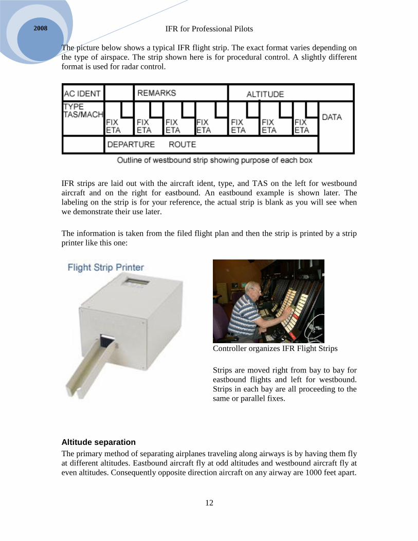
The picture below shows a typical IFR flight strip. The exact format varies depending on
the type of airspace. The strip shown here is for procedural control. A slightly different
format is used for radar control.
IFR strips are laid out with the aircraft ident, type, and TAS on the left for westbound
aircraft and on the right for eastbound. An eastbound example is shown later. The
labeling on the strip is for your reference, the actual strip is blank as you will see when
we demonstrate their use later.
The information is taken from the filed flight plan and then the strip is printed by a strip
printer like this one:
Controller organizes IFR Flight Strips
Strips are moved right from bay to bay for
eastbound flights and left for westbound.
Strips in each bay are all proceeding to the
same or parallel fixes.
Altitude separation
The primary method of separating airplanes traveling along airways is by having them fly
at different altitudes. Eastbound aircraft fly at odd altitudes and westbound aircraft fly at
even altitudes. Consequently opposite direction aircraft on any airway are 1000 feet apart.

IFR for Professional Pilots
13
Selair.selkirk.ca
For example, one airplane can be cleared eastbound at 9,000’ at the same time another is
cleared westbound at 10,000’. At some time they will be over the same location but
separated by 1,000 feet.
A reciprocal track is any track that is within 45 degrees of the reciprocal, i.e. more than
135 degrees. Therefore, in the diagram below an eastbound aircraft on V2 is considered
opposite direction to an aircraft on V1. (More on this when we examine protected
airspace shortly.)
Because altimeters are less accurate at high altitude the separation between aircraft is
increased to 2,000’ above FL290, except that properly equipped airplanes can be 1,000
feet apart in RVSM airspace. Read RAC 12.16.
Time separation
When altitude separation cannot be used, i.e. both airplanes wish to fly the same altitude
on the same route then time separation is normally used. Aircraft must remain at least 10
minutes apart when enroute except that if the aircraft in the lead is 20 knots faster than
the trailing aircraft in which case the second airplane can be allowed to proceed when 5
minutes has elapsed. Obviously the time differential will increase over time, which is
why this is permitted.
Direct Communication between Pilots
A controller can allow pilots flying the same route to maintain their own separation by
directly communicating with each other and reporting their DME. The DME must be
from the same station. For example the first airplane reports 90 DME from YWH on V2
(see above.) The trailing airplane must remain at least 10 miles behind. If it is 100+ DME
all is well. These reports must be made no less than every 30 minutes. If the trailing
airplane begins to close in on the leading airplane the pilots should communicate to
decide what to do. The airplane behind could slow down or the leader could speed up, or
they could call ATC and request an altitude change.
Radar Separation
When radar is available things are easier. It is best to think of radar separation as in
addition to procedural rather than instead of procedural separation. In other words the
same airspace must be protected whether there is radar or not, it is just easier with radar.
The existence of radar does not change the fact that full width of an airway must be
protected. Indeed, since the radar separation standard is 5 miles and airway half-widths
are 4 miles and 4.34 for LF many controllers actually enforce the 5 mile standard.
In a radar environment the controller watches the a/c on a radar scope. If the projected
flight path of two aircraft will bring them closer together than the standards permit the
controller will issue a vector or ask the airplanes to change airspeed. A vector is usually
phrased something like, “GABC, for traffic spacing turn right heading 140.” Pilots can be
assured that the controller would not issue such a clearance if it was not needed and thus

IFR for Professional Pilots
14
2008
should turn immediately. In some cases the pilot may wish to propose an alternative such
as speeding up or slowing down. This may be a good idea, but the suggestion should
always be made AFTER turning, to prevent loss of separation.
IFR for Professional Pilots
15
Selair.selkirk.ca
Chapter 2 IFR Charts
Read AIM MAP section, especially MAP 3.0 through 8.1 (online at
http://www.tc.gc.ca/CivilAviation/publications/tp14371/menu.htm)
Canada Air Pilot (CAP)
The CAP (Canada Air Pilot) is published on behalf of NavCanada. Its primary purpose is
to present IFR arrival, approach, departure, and aerodrome charts for airports with
publicly available instrument approaches. There is also a restricted Canada Air Pilot
(RCAP.)
There are 7 volumes of the CAP, each with information for a particular part of Canada.
CAP 2 covers British Columbia and CAP3 covers the Prairie Provinces; these will be the
main focus in this text.
Many companies use approach plates provided by other companies such as Jeppesen
Sanderson, known as Jepp charts. These include the same information but are formatted
differently. The FAA publishes the complete list of USA approach charts online at:
http://www.naco.faa.gov .
Pilots should read the special notices that make up the first few pages of each CAP. These
are used to disseminate recent changes to IFR standards or procedures. These notices are
removed when the information has been published in the AIM.
CAP GEN
The CAP GEN contains a great deal of useful information. Every IFR pilot should read it
cover-to-cover. The course manual includes an assignment coving the CAP GEN.
All the information in the CAP GEN can be found in other sources, especially the AIM;
however the CAP GEN, which is easy to carry in a flight-bag, makes a convenient
reference for pilots wishing to check alternate limits or the meaning of approach light
codes, etc.
LO Charts
LO Charts show all Canadian low level airways and air routes. IFR pilots must be
completely familiar with the symbols used as described in the legend.
IFR for Professional Pilots
16
2008
HI Charts
HI Charts show all high altitude Canadian airways as well as the organized track structure
used in the ACA.
Terminal Charts
Terminal charts are published for those airports with terminal radar service. The
significance of terminal radar in increasing the utilization of airspace has been explained
in chapter 1.

IFR for Professional Pilots
17
Selair.selkirk.ca
Chapter 3 Airspace Structure
I recommend that you read RAC 2 (entire section) before continuing below.
Domestic Flight Information Regions (FIR) Canadian air traffic controllers work either in IFR Centers or Control Towers. Towers are
located at controlled airports. IFR Centers are located in buildings that are not necessarily
at airports. Each center is responsible for a block of airspace called a Flight Information
Region (FIR.) In Canada there are seven domestic centers located at:
1. Gander
2. Moncton
3. Montreal
4. Toronto
5. Winnipeg
6. Edmonton
7. Vancouver
Read RAC 2.4 in your AIM before proceeding. Figure 2.2 shows the location of the
above FIRs. It also shows Gander Oceanic FIR, which is discussed below.
You will discover that Canada and the USA have agreements in certain areas such that
Canadian controllers control some American airspace, and vice versa. Detroit controls
traffic around Windsor for example, and Vancouver controls traffic at Bellingham
Washington.
Each FIR is broken into sectors with one controller (sometimes with assistance)
responsible for all IFR traffic in that sector. The dimensions of sectors are set so that no
controller is overwhelmed with too much traffic. Sectors may be expanded or contracted
throughout the day as traffic volumes change. In the vicinity of very busy airports, such
as Vancouver and Toronto, a Terminal area is designated. This usually includes a VFR
terminal area (VTA) which is intended to put VFR traffic under positive control and
reduce the chance of conflicts with IFR traffic1. IFR control in a terminal is divided into
numerous small sectors (one or two departure and arrival sectors for each runway for
instance.) At busy airports there would typically be an IFR airplane lifting off and
landing every 60 to 120 seconds. This would mean 20+ airplanes within 30 miles of the
airport, and that is far too much for one controller to handle; that is why the airspace must
be divided into small sectors.
1 The regulatory aspects of this VTA are covered in Avia 130 and 230 so will not be discussed here. Here
we are interested in understanding how the IFR aspects of the airspace actually work
IFR for Professional Pilots
18
2008
At airports with insufficient traffic to warrant a terminal one controller will handle both
arrivals and departures, and often some over-flying enroute traffic. If traffic volumes are
very low then one sector may encompass multiple airports. As mentioned, the size of
sectors changes as traffic volumes change, for example in the middle of the night one
controller may control all low level traffic in the B.C. interior which includes several
airports such as Penticton, Kelowna, Kamloops, Cranbrook and an occasional aircraft at
Grand Forks and Princeton. During the day this same airspace would be broken into
several sectors.
IFR Controllers specialize; some control high level traffic, some control arrivals, some
departures, and some low level enroute traffic. Controllers who handle airplanes that
change altitude a lot, such as arrival and departures, have an inherently higher workload,
which is why arrival and departure sectors are small. High level controllers deal with
airplanes flying in level flight and thus can handle more volume and a much larger
geographic area.
When an airplane reaches the edge of one controller’s sector s/he hands it off to the next
controller. While the airplane is within one FIR the controllers are all sitting in the same
room and able to speak with each other directly. They discuss each handoff before it
happens and can easily pass on special concerns (although they sometimes don’t.) When
the handoff is from FIR to FIR telephone coordination is needed.
On a typical IFR flight from a busy airport such as Toronto, after being cleared for
takeoff by the tower the pilot will talk next to a departure controller who may deal with
the airplane for only the first 5 miles. A second departure controller may deal with the
airplane from there to 30 or 40 miles out at which time a third controller may deal with
the airplane up to 18,000’, then a high altitude controller will take over and deal with the
flight for 200 miles or so. The airplane is then handed from one high altitude controller to
the next every 100 to 200 miles until nearing destination. Once the airplane descends
below 18,000’ a high level controller will hand it off to a low altitude controller. The
airplane will be handed off again to an arrival controller perhaps 40 miles from
destination. At a busy airport such as Vancouver arrival may be subdivided into multiple
sectors, so the airplane may be handed off to a second arrival controller 20 miles out. The
arrival controller will deal with the airplane until it is established on final approach; at
that point it will be handed off to the tower who will clear it to land.
Tower controllers work in the tower at the airport and are therefore physically separated
from IFR controllers. The IFR controller can phone the tower to coordinate handoffs if
necessary.
The above description gives you a sense of how an IFR flight is passed from one
controller to another. It gives you no idea how the controllers actually do their job. We
will deal with that in the section How ATC Works below.
IFR for Professional Pilots
19
Selair.selkirk.ca
Tower
The primary purpose of a Tower is to coordinate takeoffs and landings thus preventing
conflict on the runways. It would obviously be disastrous if an airplane tried to takeoff
while another was landing. The Tower controller’s principle job is to prevent this.
If you have flown VFR at a controlled airport such as Boundary Bay, Pitt Meadows,
Langley, or Kelowna you have a pretty good idea of how the tower controller does
his/her job. If you haven’t experienced it you can probably imagine it.
Tower controllers are NOT IFR controllers. They do NOT issue IFR clearances. Never-
the-less they play an important role in keeping IFR traffic separated. The most important
role they play is sequencing departures in accordance with IFR separation standards.
Because the tower takes this responsibility departing IFR aircraft can obtain an IFR
clearance that is not actually valid. That would not be possible at an uncontrolled airport.
Let me explain what that means.
In the section above titled Emergence of ATC I pointed out that the word clearance means
that the approved route is clear, i.e. empty of conflicting traffic. But if that was the case
as soon as you get your IFR clearance you could simply taxi out and takeoff without fear
of conflict with any IFR traffic (remember that an IFR clearance provides no assurance
about conflict with VFR traffic). At a small airport such as Castlegar (which has no
tower) that is indeed the case. But at a busier airport such as Vancouver common sense
tells us that it can’t be true. What is the actual situation?
At Vancouver an airplane departs IFR about every 90 seconds, so obviously an IFR
clearance is issued every 90 seconds. But this clearance is normally copied by the pilots
15 minutes or so before departure. So, at any given moment 10+ airplanes are all cleared
for perhaps two active SIDs (a SID is a published departure procedure details of which
we will examine later.) In addition there will be 10 to 20 airplanes that will complete the
IFR approach and land while the departing airplane taxis out but before it takes off and
leaves the area. All this traffic is obviously in “conflict” and so the term “clearance”
cannot mean what it is supposed to.
It is the skill of the tower controller that resolves the above dilemma. When each airplane
is ready it calls the tower and requests takeoff clearance. The tower controller knows the
IFR separation standards, which we discuss under HOW ATC Works below, so he checks
that no IFR traffic is on final within the permitted distance and also that the preceding
aircraft on departure has reached the required distance (usually 3 or 5 miles) and if that
airspace is “clear” he tells the pilot, “Cleared for takeoff.” At that moment the word clear
and the concept of clearance come together. The pilot can be assured that the airspace is
empty of conflicting traffic, i.e. clear. Once airborne the tower will hand the airplane off
to the departure controller who will maintain the required IFR separation, as we will
discuss below. It is important to realize that the tower establishes separation by spacing
sequential departures so that the airplanes are the required distance apart once they get to
the departure controller (the first IFR controller the pilot deals with.) Note: should a pilot
wish to make a maneuver or do anything contrary to the IFR clearance s/he has copied a
IFR for Professional Pilots
20
2008
tower CANNOT issue or approve such a request. As stated previously, tower is NOT an
IFR control agency.
The obvious question is; how are departures sequenced when there is no tower, i.e. at an
uncontrolled airport, such as Castlegar? The answer was implied above. The pilot will not
be able to get an IFR clearance until the airspace is clear. FSS will relay the clearance, or
the pilot may contact the IFR controller directly, but no clearance will be issued until the
airspace is clear. Consequently only one airplane can have an IFR departure clearance at
a time. When one airplane gets a departure clearance any other airplane wishing to depart
will have to wait until the first one takes off and leaves the area. This obviously reduces
the number of airplanes that can depart in a given period of time. This system works
smoothly when an airport has one departure per hour rather than one per minute. When a
larger number of airplanes wish to depart in a short time frame the system cannot
accommodate them. Pilots will attempt to depart VFR, or request VFR climbs to avoid
delays. We will discuss these options later, but they obviously only apply when the
weather is NOT IMC. If the weather is IMC there is nothing to do but relax and enjoy the
wait
Oceanic Control
Canada has been designated by ICAO to take responsibility for control of the Western
North Atlantic Ocean. The oceanic control center is in Gander Newfoundland. Please
note that Gander also has a domestic FIR, which was included in the description above.
Oceanic control is explained in RAC 11. Operation in the oceanic control area is mostly
covered in Avia 240 and 261. It is however done by procedural methods, which we will
turn to shortly.
IFR for Professional Pilots
21
Selair.selkirk.ca
Structure of Nav-Canada’s Airspace System Before we can discuss how ATC controls IFR traffic we need to know the terminology of
the airspace structure. You should already know this material from Avia 130. Review
RAC 2.0 before proceeding.
In what follows I will not repeat all the contents of RAC 2.0. I will try to clarify some of
the confusing aspects of the airspace system.
Something to keep in mind, which might sound very flip but it is important; airspace is
uncontrolled unless it is controlled. What I mean by that is that it is best to begin by
imagining all the airspace over Canada as being uncontrolled and therefore available for
uncontrolled IFR as previously described. From this unregulated airspace NavCanada
takes control of certain airspace, as described in RAC 2.0. The AIM naturally
concentrates on explaining what is controlled. After you read RAC 2.0 try to visualize
what is not controlled, i.e. what is not mentioned.
Northern / Southern Domestic Airspace
Take note that the purpose of this division is that in the SDA magnetic tracks are used,
while in the NDA true tracks (and runway numbers) are used. See RAC Figure 2.1
Notice that the northern domestic airspace is further divided into the northern control area
(NCA) and arctic control area (ACA) (see RAC Figure 2.3.) Pay particular attention to
RAC 2.6, it is worth reading a few times to digest fully.
Question: where does high level airspace begin in the northern domestic airspace?
Formulate your answer before reading the next paragraph.
High level airspace begins at 18,000 feet, but control is provided only at FL 230 and
above in the NCA and FL270 in the ACA. Therefore, the airspace below these flight
levels is uncontrolled.
Be sure to notice that all of the northern domestic airspace is a standard pressure region,
which is discussed below.
Low and High Level Airspace
Low level airspace is below 18,000 feet. A frequent exam question is whether or not
18,000’ is in high or low level airspace. What is your answer? Does the answer change
with altimeter setting?
18,000 feet is in high level airspace, regardless of altimeter setting.

IFR for Professional Pilots
22
2008
Standard Pressure and Altimeter Setting Regions
It is crucial to wrap your mind around the altimeter setting regions, as described in RAC
2.10 and 2.11. In the standard pressure region you set the altimeter to 29.92 and all
altitudes are referred to as flight levels. In the altimeter setting region you set the
altimeter to the reported altimeter setting of the nearest station so that your altimeter
indicates approximately the altitude above sea level. This is what you are used to doing as
a VFR pilot, but if you look at RAC Figure 2.9 you can see that most of Canada is
actually a standard pressure region.
In the Southern Domestic Airspace the high level airspace is also the standard pressure
region. In the Northern Domestic Airspace the whole area is a standard pressure region.
To put it another way, the only airspace in which you set the altimeter is the low level
airspace in the southern domestic control area (which just happens to be where you have
flown up to now).
To check your understanding, imagine you wish to fly IFR directly from Yellowknife to
Iqaluit. Can you fly at 9,000 feet?
The answer is no. You will fly at FL090.
As explained in RAC 2.11 you should set the altimeter to the airport altimeter setting for
departure and arrival, even in the standard pressure region, i.e. in the northern domestic
airspace. Pay close attention to the rules about when to switch to 29.92, this is a common
Transport Canada exam question.
An important rule is that the altimeter should be adjusted in the standard pressure region
(see RAC 2.11 transition.) Changing the altimeter from 29.92 to the current altimeter
setting is called transition (this term is part of the AMORTS briefing, covered later.
When you fly the King Air keep in mind that you transition above 18,000, or after
leaving southern airspace and entering northern.
When the altimeter setting is more than 29.92 then an airplane cruising at FL180 would
actually be more than 18,000 ASL, which means there would be plenty of vertical
separation from airplanes at 17,000 feet. But if the altimeter setting is less than 29.92
FL180 would be less than 18,000. Since the rules say that high level airspace starts at
18,000 it should be obvious that on such days FL180 does not exist. See RAC 6.4.3
which should now make sense.
Jet Routes
If you have been keeping track of what has been covered so far you know that all the
SDA at 18,000 and above is controlled (i.e. is SCA.) Within NDA, NCA control starts at
FL230 and ACA starts at FL270. There are NO lateral limits, i.e. there are no gaps within
this controlled airspace, the whole area is controlled, so any route you fly will be in
controlled airspace, and will therefore need a clearance from ATC.
IFR for Professional Pilots
23
Selair.selkirk.ca
On HI charts the airways within the high level airspace are called “jet airways.” Jet
airways do not have specific widths, unlike the low level airways we will discuss next.
In SDA Jet airway tracks are magnetic and in NDA they are true.
Low Level Airways and Air Routes
Now we will discuss the low level airspace, which you will recall is everything below
18,000 feet. Remember that low level airspace is uncontrolled except where specified. So
NavCanada specifies airways along which it provides IFR control. It also takes control of
airspace around IFR airports for departures and arrivals. The rest of the airspace remains
uncontrolled, so you can fly IFR in it without a clearance.
Low level airways are tracks between VORs or NDBs. Some airways run from a VOR to
an NDB. If a VOR is one of the navaids upon which the airways is based it is called a
Victor airway. If the airway is based only on two NDBs it is called a low frequency
airway.
When a Victor airway is based on two VORs its width is as shown in RAC 2.7.1 Figure
2.5(a)
Low frequency airways and Victor airways based on one VOR and one NDB are wider,
as shown in Figure 2.5(b) and 2.5(c).
An example of a Victor airway that is based on both VOR and NDB is V304 between
EMPRESS and LUMSDEN, on LO2. There are numerous other examples, including V23
between VANCOUVER and NANAIMO on LO1 and Vancouver terminal chart.
The base of airways is 2,200’ agl, the top is just below 18,000’ (i.e. 18,000 is not
included). Below airways is class G airspace.
The lower portion of airways is class E airspace. Above 12,500’ airways are class B. Pay
attention to RAC 1.9.2 and notice that in many areas a transponder with mode C is
required to fly above 10,000 feet on these airways (even for VFR airplanes.) Mode C is
always required above 12,500’ and VFR traffic must have a clearance to fly in class B
airspace. See RAC 2.8.2 for full details.
Reporting Points
Reporting points, marked with little triangles, will be found on LO charts along the
airways. Solid triangles represent mandatory reporting points and open triangles represent
on request reporting points. Examine the legend for the LO chart and become completely
familiar with all the symbols.
Approach and Departure Airspace
So far the only controlled low level airspace we have described is airways. These are
relatively narrow strips of airspace (do you know the exact widths – see RAC 2.7).
IFR for Professional Pilots
24
2008
If airways were the only controlled airspace it would be impossible to control IFR
departures and arrivals. Controlling arrivals and departures is one of the primary
mandates of ATC, therefore NavCanada must take control of airspace around airports.
This is done by establishing control zones, control area extensions, and transitions areas.
We will look at each in turn.
Please read all of RAC 2.7 before continuing. I do not intend to repeat it all, only provide
clarification in the hopes of making the structure easier to understand and remember.
Control Zones
You are probably familiar with control zones as a VFR pilot because you probably dealt
with them. You are used to requesting a clearance before “entering the zone.” The
controller clears you to join the circuit and then clears you to land, etc.
The base of a control zone is ground level and the top is typically 3,000’ agl. IFR
airplanes are controlled within the zone, but remember that IFR clearances come from the
Center, not the Tower.
Control zones can be class B, C, or D. It makes no operational difference to the IFR pilot,
although most prefer class B zones. In a Class B zone VFR traffic is also kept positively
separated just like IFR traffic. We are going to discuss separation shortly. Normally
separation is a concept that applies only to IFR traffic, but in a Class B zone it also
applies to VFR traffic.
In class C, and D zones VFR traffic is not positively separated, although assistance in
avoiding other traffic is normally provided if the controller has time. Note that it is done
ONLY if the controller has time.
IFR airplanes obviously fly in control zones only for the first and last two or three
minutes of a flight. However, this is usually the portion of a flight in which the airplane
transitions from IMC to VMC and may be in and out of cloud. VFR traffic must be very
careful to avoid IFR traffic in control zones. An IFR pilot in IMC gets very nervous about
VFR airplanes in the area (hence the appreciation of Class B zones).
Most control zones are round in shape with a radius of 5NM. Some controls zones have
an irregular shape. In the CFS the Obstacle Clearance Circle will show the radius of the
zone or display the words “shape irregular” – read page A50 in the CFS.
Control Area Extensions
I assume you are keeping track as we develop an image of controlled airspace. So far we
only have airways and control zones. There are bound to be gaps between the airway and
the control zone. In order to be able to clear IFR airplanes to leave an airway to an
approach procedure a control area extension will often be needed. These are described in
RAC 2.7.2.
IFR for Professional Pilots
25
Selair.selkirk.ca
Note that control area extensions have the same base and top as airways.
Transition Areas
Transition areas are similar to control area extensions except that they are based at 700’
agl.
IFR approach procedures almost always have segments that extend beyond the control
zone. A block of airspace called a transition area will be designated so that the airplane is
in controlled airspace while it performs the approach procedure.
Class F -Special Use Airspace
I am sure that controllers wish there was no such thing as Class F airspace. Be sure to
read RAC 2.8.6.
You cannot fly IFR in Class F airspace. Therefore ATC must clear you around or over it,
but NEVER through it.
There are three exceptions. You can fly IFR through Class F airspace if ________. The
answer is in RAC 2.8.6 and is a typical exam question.
Note the rules about joint use airspace, also in RAC 2.8.6. This is class F airspace that
becomes class E airspace when not in use, and therefore you can get an IFR clearance
through it.

IFR for Professional Pilots
26
2008

IFR for Professional Pilots
27
Selair.selkirk.ca
Chapter 4 IFR Flight Planning
IFR flight planning in most ways is simpler than VFR planning. You use LO or HI charts,
not VNCs and the lines representing the airways are all marked on the map for you with
the magnetic tracks and the length of the airways given; therefore you don’t need a
protractor or a ruler.
The basics of preparing the IFR navlog were covered in Avia 160 so they will be
mentioned here only very briefly.
Planning
Situational Awareness in IFR Flight
There is a “mind set” that we call thinking like an IFR pilot. Thinking like an IFR pilot
involves knowing where you are, where you are going, and how to get there. The IFR
pilot fully visualizes the entire “IFR System” knows his/her place in it and always
maintains situational awareness. Knowing the appropriate priority at any given moment is
a major key.
There are good IFR pilots and “not so good.” Knowing how to perform every IFR
procedure is NOT enough. The secret is really employing the correct skill at the correct
moment in time. As such, you must learn to recognize the indicators of what is important
at a given moment and react accordingly. Once this becomes natural we say you are
thinking like an IFR pilot. SOPs are a major key in achieving this. SOPs bring the
procedures into a repeatable format which makes an imprint on the mind creating the
necessary mind set.
Create a Script
You must have a complete image of an IFR flight. I emphasize complete. You should be
able to describe step-by-step every action to be taken from the moment you enter the
cockpit until you park and disembark. You start by saying, “the first thing I do is …….”
And the next thing is …… and the next thing is ……. Etc, all the way to the end of the
flight. If you can’t do this you aren’t ready to be in the cockpit. It is crucial to avoid
having to “figure out” what to do in flight, you must be proactive about anticipating and
figuring things out ahead of time. The key principle is anticipation.
A productive way to think about preparing for a flight is to imagine that it will be a movie
in which an actor will play the role of “you.” The actor is not a pilot, so you must script
every action s/he will take.

IFR for Professional Pilots
28
2008
The idea of creating a script is expanded further in several of the sections below. It is one
of the most valuable ideas you will come across in this book, so I hope you will heed it.
You will learn to do what I call “kitchen table flying” which I will explain later.
Aviate Navigate Communicate
There is an old saying that must become the mantra for your life as a professional pilot.
Aviate, navigate, and communicate. This is a priority list. It tells you that NOTHING is
more important than controlling the airplane. If control is in doubt then forget about
everything else and get control. A classic example is during a missed approach procedure.
The airplane must be established in a climb with the gear and flaps retracted. Instructors
are often flabbergasted to see how many pilots will push the PTT button and start talking
on the radio while the gear is still down and the climb rate is far less than the safe value; I
have even seen people sinking toward the runway attempting to communicate when they
clearly need to aviate. Make a resolution to step through this three step priority list
continuously throughout your flights.
Everything you do as a pilot can be put into one of these three categories. What you need
to do is develop a mental discipline that whenever you do ANYTHING you slot it into
this priority sieve. For example when your find yourself wanting to reach over and tune a
new VOR frequency (navigate) you should consciously think, “are my wings level, is my
altitude steady? O.K proceed.” Personally I literally “talk” silently to myself as described
here, but in some fashion you must confirm that aviate is OK before you do any
navigating and both aviate and navigate are OK before you communicate.
If you have an autopilot then it largely takes care of aviate meaning that you can more
easily concentrate on navigate and communicate. If there are two pilots, and no autopilot,
then one should always be aviating while the other can concentrate on navigating and
communicating. In these situations the aviate, navigate, and communicate priority still
applies but failure to consciously think about it may not carry a noticeable penalty – most
of the time. You should however strive to keep this three level priority in your mind all
the time and train yourself to scan the flight instruments (confirm aviate) just before
every navigation change or communication. This will keep you mentally prepared to
handle malfunctions such as autopilot failure or incapacitation of your copilot.
Single Pilot – No Autopilot IFR
The hardest thing in the world to do is single-pilot IFR with no autopilot. Well, maybe
climbing Mount Everest with no oxygen is harder. But single-pilot IFR is right up there.
To do it you must absolutely be committed to aviate, navigate, and communicate priority.
An airplane will drop off into a spiral dive, or slump below the minimum climb gradient
on a missed approach, very easily if you divert your attention to navigating before you
have full trimmed control. It is critical to keep the airplane in good trim during single-
pilot IFR. Never communicate before aviate and navigate are confirmed OK.

IFR for Professional Pilots
29
Selair.selkirk.ca
What I find works for me is a self authorization mantra. When flying single pilot I
constantly ask myself, “What should I do now?” At every moment I have some answer
that comes into my mind. I run this through my mind as though some part of me is asking
permission from another part to do something. I describe this as my “first officer” asking
my “captain” (I am both of these at once). When the first officer wants to do something,
such as report on the missed approach, the captain checks that pitch and bank are steady
and airspeed and vertical speed are as desired, he then checks that nav radios are as
needed (I use the TSI system described below) and if these are all OK he authorizes the
first officer to make the call. This has become so ingrained in me that I honestly cannot
press the PTT button without scanning the AI, Alt, VSI and radio stack first. And I cannot
reach for a nav radio without scanning the AI, Alt, and VSI first. This is pretty basic stuff,
but if you develop a bad habit early in your flying it is hard to break later so work on this
diligently.
Conducting a WAT and AMORTS briefing single pilot with no autopilot is very
challenging. I would go so far as to say that you cannot do it “cold.” By cold I mean
without having done it previously. This means that you must examine every plate you
could possibly use on a flight and run through an AMORTS briefing for it as part of your
preflight preparation. That way when you do the briefing in flight you will have a
reasonable chance of not missing anything.
In closing this section I would like to say that by far the most common mistake for
beginners is to worry too much about communicating. Take a hold entry for example.
When you enter the hold you are supposed to report, but what difference does it make if
you report the second you pass the station or 30 seconds later? It doesn’t really matter.
But if you don’t turn, or you spiral in the turn that does matter. Yet time and again new
IFR pilots will press the PTT and start talking without turning, or will loose altitude in the
turn because pitch is not under control, or the airplane is not in trim. Don’t let this happen
to you.
Preferred IFR routes
Start by examining the CFS section C for any preferred IFR routes. There are both low
and high altitude preferred routes depending on the type of airplane you are flying.
If there is no preferred route published that is usually because there is not enough traffic
between the airport you are flying from to the one you are going to to warrant a preferred
route. However, if you are flying out of or into an airport that does have preferred routes
you should select the preferred route for an airport in the right direction. For example
there is no preferred low altitude IFR route from Vancouver to Castlegar – but there a
preferred route to Princeton – this route should be used by an airplane departing
Vancouver for Castlegar.
You should almost always file the preferred route. It causes a great deal of trouble for
ATC if you don’t. Normally you will be cleared for the preferred route even if you file
IFR for Professional Pilots
30
2008
something else. Therefore, if there is an important reason why you require an alternate
route indicate that in the remarks section of your flight plan – an example might be
“Aircraft on unpressurized ferry flight. Request route due to lower MEA.”
LO Charts – Distances, Bearings, etc.
Start by examining the legend for the LO and HI charts; you must get to know all the
symbols on the map. Bearings and distances are the most obvious thing, but by no means
the only thing, they provide. Let’s look briefly at a few key items in the legend.
Aerodrome symbols can be black or green – what is the difference? (IFR as opposed to
VFR only. Note that the IFR could be in the RCAP, not the regular CAP in some cases.)
Can you tell the length of runway at an airport without opening up your CFS? (Yes, as
well as type of runway surface and whether or not the runway is lighted. Be sure to know
how to interpret these symbols.)
Are VOR and NDB symbols always located in the exact correct position on LO charts?
(No, sometimes they must be offset for clarity, however the compass rose is centered on
the correct location for the VOR.)
How can you tell whether you should be flying at an odd or even altitude on a particular
airway? (the airways symbols have a pointed end – this indicates the direction for even
altitudes.)
Looking at LO2 can you tell whether Calgary International has a Class B or a Class C
control zone without looking in the CFS? (Yes, check the symbols in the legend.)
The box that surrounds the frequency for NDB or VOR stations can be either thick or
thin; what is the difference? (Thick lines indicate the nearby airport has a FSS.)
How are RCO and DRCO sites found on the map? (See the legend for the symbols and
read about using DRCO in CFS page D36 and AIM RAC 1.1.3.)
The LO chart shows all the airways and navaids needed for navigation. As an example
look at the LO2 chart and locate V317 from YVR to YNY. You can see that the airway
uses radial 014 outbound from YVR; this track applies all the way to LYTON. From
LYTON the airway follows radial 237 to YNY; the track on your navlog would be 057.
Note that this V317 passes numerous intersections (MODY, JANEK, LYTON, CHAPT,
FELKO) Only LYTON needs to be on the navlog (and in the GPS flight plan) because it
is the only waypoint at which the track changes. The LO chart gives the distance between
each waypoint; make sure you can find all the distances. For example the distance
between CHAPT and FELKO is 25 NM.
IFR for Professional Pilots
31
Selair.selkirk.ca
What is the distance from YVR to LYTON. You might be thinking that you can find the
total distance on the map in a square box – but it is important to realize that distance
totals are provided only between navaids and compulsory intersections. LYTON is not a
compulsory intersection and therefore the total distance of 202 on the map is from YVR
to YNY. Contrast this with the earlier example of V342 from YVR to YDC; in that case
CILLI is a compulsory intersection so the distance from YVR to CILLI of 69 NM is
provided on the map. To get the distance from YVR to LYTON you will have to add up
43+23+21.
What is a mileage breakdown point – and what symbol is used? (Look it up in the legend
and then look for some examples (there is one on V300 between Thunder Bay and Sioux
Narrows.)
There are a couple of small differences between Canada and the USA that you need to
know about because the LO charts cover some USA airspace. In Canada the MEA can
change at any intersection and if you are crossing over that intersection you must be at
the higher of the two MEAs. In the USA they provide a minimum crossing altitude
(MCA) that you can cross the intersection provided you climb at 200 ft/nm to the higher
MEA. Examine the legend to find the symbol for MCA and look to see if you can find
any examples (they will only be in USA airspace.)
Navlog Preparation
You learned to complete a navlog in Avia 160 so this section will provided only a few
comments highlighting the differences between IFR and VFR flight planning.
If using the Electronic Navlog (ENL) select the MT-navlog. Or, if you are planning a
round robin IFR as we do in the last few lessons of the syllabus use the round-robin
navlog.
The navlog should always start from the departure airport and the first waypoint should
normally be the location where you intercept the airway structure. This point is likely to
be an NDB, VOR, or airway intersection. The distance and time for this first leg should
be a reasonable estimate. Be sure to examine the SID and allow for any vectoring or other
maneuvering you will do. In other words; the first leg is almost always longer than the
straight-line distance from the airport to the first waypoint.
After the first waypoint the navlog is very simple to layout. The bearings and distances
are all provided on the LO and HI charts. Make one leg for every change of track. This
will require a new leg after each station passage, and separate legs if the airway has a
dogleg, such as V342 between YVR and YDC (i.e. there should be a leg from YVR to
CILLI and another from CILLI to YDC.)
The last waypoint on the navlog should be the location where the approach or STAR
begins.

IFR for Professional Pilots
32
2008
The time for the STAR and approach should then be estimated and entered on the navlog.
The fuel-flow used for the approach should be conservative. For a piston engine airplane
it is usually best to assume cruise fuel flow since this will be on the safe side. For a
turbine airplane the fuel flow may increase in the warmer air at low altitude, so take care
to allocate a high enough value.
Allocate 45 minutes of reserve time at cruise fuel consumption.
With all the above complete your navlog now indicates to you the time the flight will take
and the minimum legal fuel requirement. You must now decide how much contingency
fuel to add. As a student pilot you are spoiled by the ability to add all the fuel you want.
In fact we always depart with full tanks. But, in the real world flying you will have to
establish a reasonable contingency fuel. At the major airline level the question of how
much contingency fuel is required is becoming a huge cost factor. It costs money to carry
around unneeded fuel “just in case.” So, it is important that you consider carefully how
much contingency fuel you actually need. Please read the Air Canada Fuel Bulletin on
our website CRM page.
Selecting an Alternate
Unless specifically authorized in an Air Operator Certificate all IFR flight plans require
an alternate (see RAC 3.14.)
An alternate airport is a safe place you can go and land if the weather drops below
minima at your destination. As such the alternate is a critical safety feature of your flight
planning, especially if the weather is marginal.
Your CAP GEN and AIM RAC 3.14 give the rules for selecting an alternate. This is
extremely crucial stuff but a bit difficult to interpret – so read it carefully.
There are three standard alternate minima; these are 400:1, 600:2, and 800:2. 90% of the
time one of these will apply. The first table in RAC 3.14 shows that these apply when the
airport has multiple ILS, one ILS, or non-precision approaches respectively. It is
important to get your mind wrapped around the idea of the standard alternate minima –
do so before moving on.
When standard alternate minima apply you are permitted to use a sliding scale. For
example if your alternate airport is equipped with an ILS standard alternate minima are
600:2, but you can also file this airport as an alternate if the forecast is 700:1½ or 800:1.
Make sure you understand when the sliding scale is applicable.
If the alternate airport has “unusually high” approach minima then standard alternate
minima DO NOT apply and the weather forecast needs to be greater – this requirement
should be obvious, so if it isn’t obvious then stop and think about it for a minute. To meet

IFR for Professional Pilots
33
Selair.selkirk.ca
this obvious safety need the rules state that the alternate minimum ceiling must be 300
feet above the approach MDA and the visibility must be 1 sm more than the approach
visibility. For example Grand Forks approach minima are 3360:3 so after doing the math
you get 3660:4. This however is NOT the correct answer – but it is a good start.
The 3660 must rounded off in accordance with note 4,– it is critical for you to read note 4
of RAC 3.14 and know the rules for rounding off altitudes.
The correct visibility is actually 3sm, not 4sm, because of note 5.
Therefore, Grand Forks can be filed as an alternate if the TAF forecasts 3700:3.
Of course there is a problem, because there is no TAF for Grand Forks. Therefore note 3
applies and we must ensure from the GFA that there is no cloud below 6100 asl (this is
1000 above the HAT) and there is no CB in the GFA and the visibility is forecast to be at
least 3sm.
Finally we must confirm that paragraph 3 does NOT apply. This paragraph starts with the
words, “Pilots can take credit for GNSS …” It is important to note that the requirement is
that there be conventional approaches at the destination. So if CYCG is the destination it
has NDB and Localizer approaches, so we can file Grand Forks as an alternate as
described above. But, if CAD4 (Trail) is the destination we cannot – because Trail only
has an RNAV approach. In this case we would use the clause for NO IFR APPROACH
AVAILABLE. The GFA would have to show ceiling no lower than 10,500 asl (MOCA
on G1.)
In most cases you base your alternate selection on the TAF for the destination airport.
The basic idea is that the forecast must be at or above alternate minima at the time you
will arrive. But, what if the forecast includes a TEMPO or BCMG clause? The rules for
this are in RAC 3.14. The basic idea is that for TEMPO and BCMG you must use the
least favorable weather forecast for the period. But, for PROB forecasts you are given
more leeway; as long as the overall forecast is above alternate minima you can accept a
lower PROB provided it is not lower than the approach minima.
The last point to note is that you can only base your alternate on approaches you are able
to fly. For example if your glideslope is unserviceable you cannot use the ILS, or if the
wind favors runway 27, you cannot use the approach on runway 09, etc.
You can see from the above that there are lots of twists and turns to choosing an alternate.
You will have to be very careful not to miss anything.
Filing an IFR Flight Plan
Read RAC 3.16 carefully before proceeding.

IFR for Professional Pilots
34
2008
You should be aware of the codes for filing combination IFR and VFR flight plans even
though they are not used very often – if they are needed you can always look them up, the
important thing is to know that these codes exist.
The planned departure time is more important on an IFR flight plan than VFR. In some
cases if flow control is in effect you are expected to be within 3 minutes of your filed
takeoff time. In such cases you normally check with clearance delivery prior to engine
start to confirm your departure slot time. When flow control is not in effect it is still
important that you be reasonably close to your filed departure time. Your flight plan must
be filed at least 30 minutes before your planned engine start – if not the system will not
have enough time to process your flight plan. If you file a flight plan and then find out
your passengers are going to be an hour late be sure to call and have your departure time
amended.
RAC 3.16.6 (the speed and altitude boxes.) Once you file the speed on your flight plan
you must fly that speed accurately (see RAC 8.3.) If you cannot do so (perhaps due to
turbulence or a malfunction) you need to inform ATC. This is less important in a radar
environment, but it is critical when you are in a procedural environment such as an
oceanic flight. However, there is no need to worry about slowing down during times such
as vectors to an approach. ATC also typically expects aircraft descending on STARS to
adjust speed – while there are not regulations authorizing these speed changes they are
common practice so you don’t need to worry that ATC will be upset with you. If your
speed or altitude changes at any time during a flight enter the new speed and altitude in
the same format described in RAC 3.16.6 as part of your route (see below.)
RAC 3.16.6 (route box) – normally the first entry in your route is the point where you
will intercept the airway. This is often a VOR or NDB or and airway intersection.
Typically this will correspond to the first waypoint on your navlog. In some cases you
may start the route with an airway that passes by thus indicating to ATC that you will
make an intercept of the airway – but this does create a slight ambiguity since the precise
point you will intercept the airway is not defined.
When your follow a single airway there is no need to enter waypoints along the airway;
for example you can file V300 from Castlegar all the way to Newfoundland. When you
change from one Victor airway to another the transition point must be clear; however this
will always be at a VOR or NDB so simple insert the nave of the navaid between the two
airway names, for example V300 YDC V342 … (which means that you will follow V300
to Princeton and then V342 after Princeton.)
Often it will be necessary to change altitude and or airspeed during the flight. Changes to
altitude and speed are inserted in the route at the point they occur. The format is identical
to the format for speed and altitude described above. For example if the new speed is 245
KTAS enter N245 in the route. If the new altitude is 12,000 feet enter A0120 in the route.
An important point when filing the route on your flight plan is whether or not to file a
STAR as part of your route. Read RAC 9.2 before continuing.

IFR for Professional Pilots
35
Selair.selkirk.ca
There are important differences between Conventional STAR and RNAV STAR from a
flight planning point of view.
If you file a Conventional STAR this tells ATC that you wish to fly that STAR but you
still require a clearance for the STAR as you near your destination; thus, even if you have
been cleared via the “flight plan route” you would still hold at the depicted hold location
at the start of the STAR if you are not cleared specifically for the STAR.
If you file an RNAV STAR it becomes a “part of your route” (see RAC 9.2.3) and
therefore if you are cleared via “flight plan route” you are in effect already cleared for the
STAR. In accordance with RAC 9.2.3 you would NOT hold, you would fly the STAR all
the way to the DTW without the need for further clearance. At the DTW follow the
instructions on the particular STAR plate.
RAC 3.16.7 (time enroute box) on your flight plan is very important – especially if you
were to have a communications failure. Read the communications failure procedures in
RAC 6.3.2 and CFS section F before continuing.
From your reading about communications failure you know that if you file an RNAV
STAR in your route, and you are cleared via the flight plan route you are expected to fly
the STAR and land. Therefore, the enroute time on your flight plan should run from
takeoff to landing, just as it would on a VFR flight plan.
From your reading about communications failure you know that if you DO NOT file an
RNAV \STAR you require additional clearance before flying an arrival procedure and an
IFR approach. In the event of communications failure ATC expects you to start the
arrival/approach at the flight plan time. Therefore it is important that your flight plan time
run from takeoff to the time when you would start the arrival/approach. This is very
different from a VFR flight plan. Be sure you understand the difference.
The rest of the flight plan form is filled out exactly like a VFR flight plan.

IFR for Professional Pilots
36
2008

IFR for Professional Pilots
37
Selair.selkirk.ca
Chapter 5 IFR Departures
The departure procedure gets you safely from takeoff to the enroute environment at a safe
altitude. Once you are enroute you will be above the MEA and thus safe from a terrain
clearance point of view. But, during the departure you necessarily fly below the MEA as
you climb. It is therefore a critical time of flight and it is supremely important that you
have a procedure that ensures safe clearance from terrain and obstructions.
In Canada most airports have developed IFR departure procedures that you can follow
and which ensure your safety. But, not every airport has such procedures (and in some
parts of the world you will be completely on your own) so you must be able to come up
with a procedure of your own. (At the time of this writing the IFR departure procedure in
CYCG is suspended – thus creating the equivalent of an “un-assessed airport.”)
The simplest IFR departure is to climb in VMC conditions up to the MEA. On many days
this is feasible. Once you are above the MEA you know you are safe; therefore as long as
you remain VMC during the climb you will be OK. You have probably observed Jazz
climb visually up the Arrow Lake for example.
In the days before Canada published IFR departure procedures our most reliable and
safest method of making IFR departures was to climb visually to the missed approach
point (MAP) for one of the IFR approaches at the given airport and then follow the
missed approach procedure (this is the current best way to depart CYCG given the
suspended departure procedure.) The MAP is usually at the threshold of a runway so
getting to it after takeoff can be a bit tricky – but as long as you can provide visual terrain
separation to that point you know you are safe to enter cloud on the missed approach
procedure.
The other procedure that we used to use before departure procedures was to fly an IFR
approach backwards. If you are able to takeoff in the opposite direction to the approach
and can climb rapidly enough to remain above the published MDAs on the approach you
once again know you are safe. This is not always as easy as it sound because IFR
approaches can descend as steep as 400 feet per nautical mile, which is a very steep
climb. But, if your airplane can make the climb this procedure is also safe.
If the pilot intends to provide visual terrain separation on departure s/he should tell the
controller and get approval. This is important because the airplane must be provided
traffic separation service and the controller cannot do that effectively if s/he does not
know the route the pilot intends to fly. For example, if the departure procedure calls for a
climb overhead the airport before proceeding on course but the pilot intends to proceed
on course without climbing overhead s/he should tell the controller that.

IFR for Professional Pilots
38
2008
Often on a SID departure ATC provides vectors to the airway after takeoff. By rule the
controller cannot vector the airplane below the minimum radar vectoring altitude – with
one exception. If the pilot says, “I can maintain my own terrain separation” the controller
can vector the airplane below the vectoring altitude. Knowing this can save time; it would
save more if pilots knew what the minimum radar vectoring altitude is, which they don’t.
But, when you fly the same route every day you can figure it out (because the controller
turns you at the same altitude day after day.) If you are in VMC conditions you can tell
the controller, “I am able my own terrain separation” and get a turn toward your airway
earlier.
To recap – we have three procedures that we could use if there is no published IFR
departure procedure:
1. Climb in VMC until at the MEA
2. Follow a published missed approach procedure
3. Fly an approach backwards
If the above options are not viable the only alternative is to develop an IFR departure
procedure. Transport Canada no longer funds this activity, which means that users must
fund the process (very expensive.)
CAP Departure Procedures
Read RAC 7 before proceding.
Departure procedures are published in the CAP for most airports. These procedures are
designed by professional IFR procedure designers who follow complex rules to ensure
that the procedures are safe. These rules are in the document TP309, a copy of which is
on our website. It is however far too complex for pilots to realistically know all the rules.
There are however a few basic principles of IFR departure procedures that you must
know.
The procedure designer analyzes the terrain surrounding the airport. S/he must determine
whether or not a departing airplane has any risk of hitting an obstruction. Of course if a
pilot was to level off immediately after liftoff then the airplane would surely hit
something, so the designer makes certain assumptions, these are:
1. The airplane will be at least 35 feet agl when it crosses the departure end of the
runway
2. The airplane will climb on a gradient of at least 200 ft/NM
3. The airplane will not turn until it reaches 400 feet agl
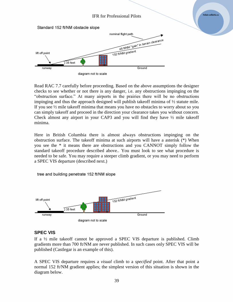
IFR for Professional Pilots
39
Selair.selkirk.ca
Read RAC 7.7 carefully before proceeding. Based on the above assumptions the designer
checks to see whether or not there is any danger, i.e. any obstructions impinging on the
“obstruction surface.” At many airports in the prairies there will be no obstructions
impinging and thus the approach designed will publish takeoff minima of ½ statute mile.
If you see ½ mile takeoff minima that means you have no obstacles to worry about so you
can simply takeoff and proceed in the direction your clearance takes you without concern.
Check almost any airport in your CAP3 and you will find they have ½ mile takeoff
minima.
Here in British Columbia there is almost always obstructions impinging on the
obstruction surface. The takeoff minima at such airports will have a asterisk (*) When
you see the * it means there are obstructions and you CANNOT simply follow the
standard takeoff procedure described above.. You must look to see what procedure is
needed to be safe. You may require a steeper climb gradient, or you may need to perform
a SPEC VIS departure (described next.)
SPEC VIS
If a ½ mile takeoff cannot be approved a SPEC VIS departure is published. Climb
gradients more than 700 ft/NM are never published. In such cases only SPEC VIS will be
published (Castlegar is an example of this).
A SPEC VIS departure requires a visual climb to a specified point. After that point a
normal 152 ft/NM gradient applies; the simplest version of this situation is shown in the
diagram below.

IFR for Professional Pilots
40
2008
In the above example the airport is surrounded by mountains as is typical of airports in
British Columbia. In this case a standard 152 ft/NM cone based at the ground is not an
option. Let’s say the procedure designer discovers that if the cone is centered on the
airport but based at 900’ agl no obstacles penetrate it. The departure designer will then
simply instruct pilots to climb over the airport visually to this altitude before proceeding
on course (BPOC).
“SPEC VIS Climb visually over airport to 2,300’ or above BPOC.”
In the example above the BPOC point is directly over the airport. This is very common,
but by no means the only possibility. It is important for the pilot to read the departure
instructions carefully and understand where the BPOC point and understand that the 152
ft/NM cone is centered there, and based at the specified altitude.
Pilots usually prefer that the departure procedure designer specify the lowest possible
altitude for the BPOC point. Consequently it is usually the case that the cone is based at
an altitude from which climb can be made in some direction but not necessarily all
directions. There are numerous examples of this, Port Alberni for instance:
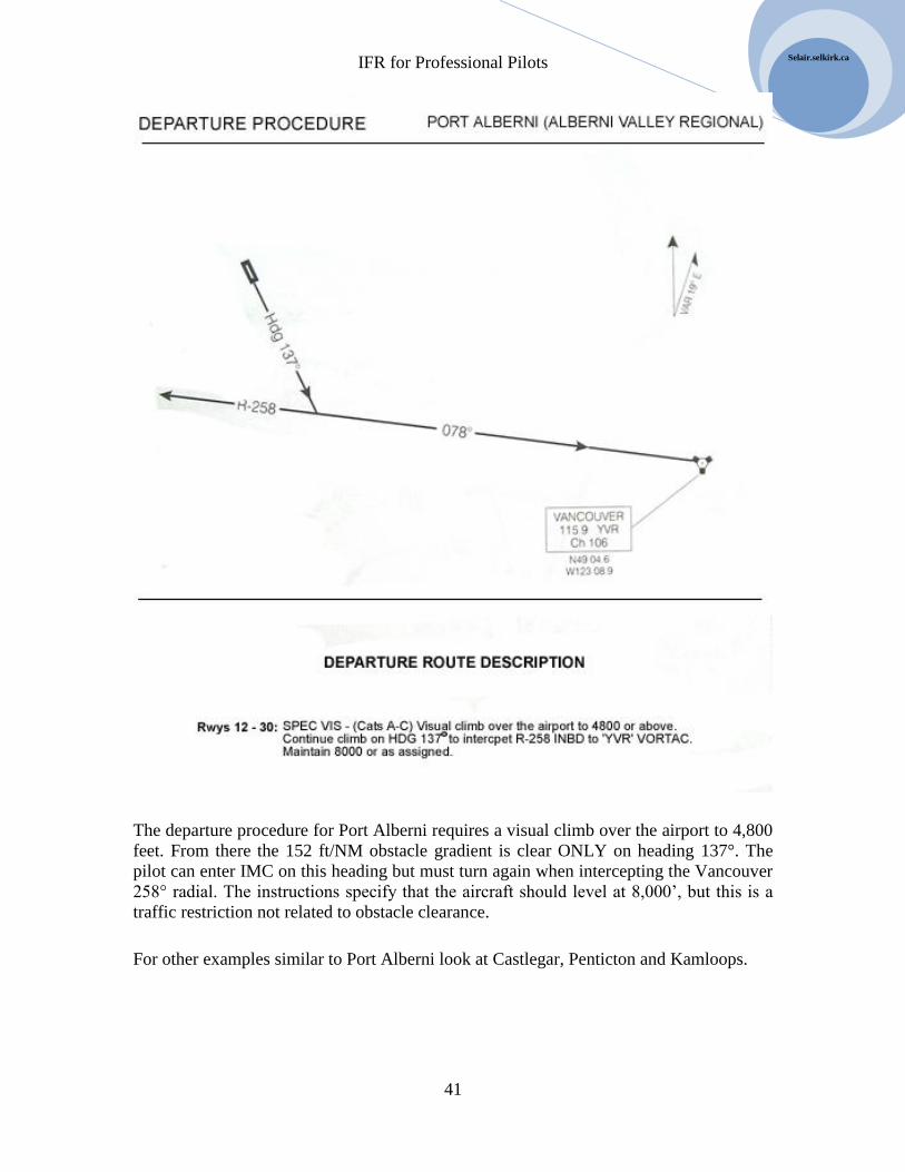
IFR for Professional Pilots
41
Selair.selkirk.ca
The departure procedure for Port Alberni requires a visual climb over the airport to 4,800
feet. From there the 152 ft/NM obstacle gradient is clear ONLY on heading 137°. The
pilot can enter IMC on this heading but must turn again when intercepting the Vancouver
258° radial. The instructions specify that the aircraft should level at 8,000’, but this is a
traffic restriction not related to obstacle clearance.
For other examples similar to Port Alberni look at Castlegar, Penticton and Kamloops.

IFR for Professional Pilots
42
2008
Unassessed Runways
It was mentioned earlier that not every runway in Canada has been assessed for IFR
departures. What should a pilot do if departing from an airport that has not been
assessed?
If the airport is to be used on a regular basis, especially for commercial purposes, it may
be worth the expense of having a professional assess the runways. If a standard ½ mile
departure is safe it would be good to know that. If a greater than standard climb gradient
is needed it is important to know that, and if SPEC VIS is required it would be good to
find the most efficient safe route.
For an occasional IFR departure, such as a medevac from an uncontrolled airport that
normally does not handle IFR traffic, the pilot is on his own to determine a safe
procedure and decide whether standard conditions exist.
If the airport is in the middle of Saskatchewan the pilot might be satisfied to check the
local charts for towers and finding none assume that standard conditions apply. The pilot
might also consider that the turbo-prop airplane s/he is flying normally climbs at a
gradient of 1,000+ ft/NM. Given these facts the pilot might feel confident that a takeoff
in ½ statute miles is safe. Most likely the pilot would turn at 400’ agl, but it is CRUCIAL
to realize that this would be no more than a habit. If no assessment has been formally
done then no criteria exist.
In more rugged parts of Canada the pilot might realize that obstacles do exist and that a
standard ½ mile takeoff is NOT advisable. In this case the pilot must devise a “home
made” SPEC VIS procedure. The pilot can do this in many ways but in most cases the
pilot will use one of the following strategies:
1. A visual climb to airway MEA. Of course the weather must be quite good for
this.
2. If there is an IFR departure procedure nearby the pilot may choose to fly VFR to
that airport and then depart IFR.
3. If there is an IFR approach procedure the pilot may climb visually to the missed
approach point then follow the missed approach procedure. Alternatively the
pilot may fly the approach procedure backwards
It should be clear that when departing from an unassessed runway great care must be
taken. The law permits ½ mile takeoff, but the safety of doing so is questionable. The
pilot must be completely certain that no obstacles impinge on the aircraft’s climb
gradient.
IFR for Professional Pilots
43
Selair.selkirk.ca
Departure alternate
Departure alternates at required when a commercial air operator takeoffs at weather lower
than the published takeoff weather in the CAP or lower than the published approach
minima in the CAP. You will learn the details in your Air Regs course – you should read
CAR 724.26.
If a departure alternate is required it is filed on the flight plan in accordance with RAC
3.16.7
IFR Clearance Review
Just before takeoff you should conduct an IFR clearance review. At Selkirk College we
have this on our C-172 and B85 checklists. In the future, if it is not on your checklist you
must do it anyway. Reviewing your clearance before takeoff is the single most important
thing you can do to ensure a safe non-stressful flight. It is surprisingly easy to get
airborne without realizing you don’t know where you’re going. That anyone could be so
stupid or incompetent might seem implausible to you, but once you start flying IFR you
will see that it can easily happen if you don’t consciously develop a clearance review
procedure.
An IFR clearance review is a three step process:
1. Read the clearance
2. Trace the route on SID, Terminal, or LO charts
3. Get all radios setup
You start by reading the clearance which by this point you will have copied. Make sure
you understand it and accept it. If necessary ask for clarifications or amendments. Let’s
say your clearance is something like, “GABC is cleared to Somespot airport via the
Clover 3 departure flight plan route, squawk 4321.” Flight plan route is obviously
acceptable. You would then read the Clover 3 SID and note the altitude you are cleared
to, the frequency and location to contact departure control, and any special restrictions
such as climb gradients or com-failure procedure.
The second step is to trace the route you will fly on your charts. When the clearance
includes a SID use that chart first, if not then go directly to the LO or terminal chart as
applicable. Put your finger on the map at the takeoff point and move it along the route as
you create a script for yourself (see appendix about scripting.) The SID must be translated
into a step by step process such as climb on heading 270 to 3,700’, turn right direct YAB
VOR, maintain 5,000’. Continue the process of writing this script for yourself deep
enough into the flight to connect up with the script that you should already have (see
scripting appendix.) If you have been cleared via flight plan route you only need to build
a script to the end of the SID because you already have one for the rest of the route from
your “kitchen table flying.” If you are cleared for an unanticipated route you should go

IFR for Professional Pilots
44
2008
further and build a complete script. This won’t happen very often. Frequently the
unexpected route will be one you have flown before and you will be able to recall the
script you used previously. But, if you get a totally unexpected and unfamiliar route you
need to examine it, and script it, before you takeoff. You will get quite quick at doing this
with practice. We will do numerous exercises of scripting in this course.
The third step is to setup all the radios. To do this we use a framework called Tune,
Setup, Identify (TSI), which is described in detail elsewhere in this text. If you have a
good script this step is pretty easy.
Once you have completed these three steps you should be ready to go. You would
normally then conduct a crew briefing if you have a copilot and then takeoff.
Crew Briefing
In a two-pilot environment it is normal to conduct a takeoff briefing just before departure.
This is normally just after the IFR clearance review described above and before calling
the tower for takeoff clearance. The primary content of the crew briefing is to review the
speeds and procedure for the takeoff and to clarify who will do what in the event of an
emergency.
The crew briefing should also clarify the IFR departure procedure. This should be very
short, for example simply saying, “We will climb runway heading to 5,000’ and expect
radar vectors.” It is not usually wise to put too much information in the briefing because
if you do you risk information overload and a tendency for the other pilot to tune you out.
But you should note the altitude you are cleared to and any turns that will be required in
the first minute or so. I like to think of this as priming the other pilot to act as an altitude
and heading alerter. If you say to yourself, “what do I want the other pilot to draw my
attention to if I get distracted?” your answer will generally tell you what to include in the
briefing. You will find that it is very easy to shoot through your assigned altitude on
departure (especially in the King Air) so you will want the other pilot to draw that to your
attention. It is also easy to forget a turn after takeoff since most takeoffs involve climbing
runway heading until ATC instructs you to turn. So these are the sorts of things to include
in a briefing. Conversely, things that won’t happen for many minutes into the flight have
no place in a briefing. They can be briefed later at a more appropriate time. Things that
are totally SOP do not need briefing (unless you have a new copilot who doesn’t know
the SOPs). Briefing SOPs is a good way to bore the other pilot into ignoring you.
VFR Departure
Read RAC 6.2.2
A pilot may request permission to depart VFR and pick up an IFR clearance in the air.
Obviously the weather must be VFR to do this. It is necessary to have ATC permission to
do this. When the aircraft takes off it is NOT IFR. It does not become IFR until it
receives a clearance. Why would the controller not approve the request?
IFR for Professional Pilots
45
Selair.selkirk.ca
If two airplanes are both trying to depart at the same time on the same route ATC will be
reluctant to authorize a VFR departure (presumably for the second airplane) because it is
difficult or impossible to establish separation. In other words the airplanes will remain in
close proximity to each other. In this case ATC will refuse the request and the second
pilot should do the entire flight VFR or wait on the ground for an IFR clearance.
VFR departures do work well when the conflicting traffic is in the opposite direction.
Obviously an outbound airplane will pass an inbound and quickly reach a point at which
separation exists. Once ATC determines separation is adequate an IFR clearance can be
issued.
Remember that when departing VFR the airplane is not permitted to enter IMC
conditions.

IFR for Professional Pilots
46
2008

IFR for Professional Pilots
47
Selair.selkirk.ca
Chapter 6 Enroute Procedures
Altitude Reports
Read RAC 8.4
Although RAC 8.4 specifies that it is only compulsory to report reaching your assigned
altitude in a non-radar environment it is standard practice to always report reaching the
assigned altitude.
Note that on your initial call to departure the controller will be checking the accuracy of
your mode-c so you should be accurate about indicating your altitude.
The second paragraph of RAC 8.4 lists the times when you should report your altitude –
make sure you know and follow this list.
Climb and Descent
Read RAC 8.5
Know the meaning of the phase “when ready.”
When you vacate an altitude ATC can assign the altitude to another aircraft so you should
climb or descend at least 500 fpm to avoid possible conflicts.
Know the rules about making visual climbs and descents – these are often very handing
to get a climb when there is a lot of traffic. Notice that you cannot do visual climbs in
Class B or A airspace (i.e. not above ___________ altitude?)
1000 on Top
Read RAC 8.8
We don’t normally use 1000 on top in training – and it is not operationally common
either, but in a few situations it may be advantageous. The main advantage is that two
airplanes can both fly at the same altitude because separation is not provided. This might
allow two airplanes to cruise at 9000 avoiding the need for on to climb to 11,000 and use
oxygen (this is the most likely reason to use it.)
Clearance Leaving or Entering Controlled Airspace
Read RAC 8.9

IFR for Professional Pilots
48
2008
Also read RAC 9.3 (example of an airplane being cleared to descend out of controlled
airspace via a particular IFR approach.)
Also read RAC 9.4 – descent out of controlled airspace. This is how you would go about
landing at an airport with no IFR approach such as Nakusp or Creston, etc.
Clearance Limit
Read all of RAC 8
An important concept is the clearance limit – read RAC 8.10. The clearance limit is an
important concept especially if you have a communications failure. You cannot proceed
beyond the clearance limit until the expect further clearance time. Thus if you are cleared
to hold or otherwise cleared “short” you need a procedure to follow in the even of a
communications failure. (re-read RAC 6.3.2.)
IFR Flight in Uncontrolled Airspace
Read RAC 8.11
It is important to know this information for the INRAT exam. It is also quite common to
fly in uncontrolled airspace especially early in your career – so you should know what to
do.
Chapter 14 contains details of flight in uncontrolled airspace
Position reports
When you are radar identified you do not have to make IFR Position Reports.
If you are not radar identified then you must report all compulsory reporting points and
navaids along your route. Compulsory reporting points are marked as solid triangles on
the LO and HI charts.
There was a time when IFR position reports were very important. They still are important
to international pilots flying oceanic routes. However, over the North American continent
you will be in radar contact a lot of the time and therefore many pilots have forgotten
how to make a good IFR Position Report.
The format of an IFR position report is on the back cover of your CFS (which you should
always have onboard.)

IFR for Professional Pilots
49
Selair.selkirk.ca
The controller uses your time and ETA for the next reporting point to prevent any
conflicts with other traffic so safety demands that you be accurate. If you subsequently
discover that your ETA is off by more than 3 minutes let the controller know. S/he may
have to take action to prevent a conflict so the sooner you let them know the better.
Altimeter Setting Procedures during Abnormally High Pressure Weather
Be sure to read RAC 12.12
The gist of this rule is that older altimeters cannot be set to an altimeter setting more than
31.00 inches, so ALL pilots will 31.00 whenever the actual altimeter setting is more than
31.00 – ATC will confirm this with you.
Once you reach the FAF you change your altimeter to the actual setting if you are able. If
you cannot do that you simply leave the altimeter set to 31.00 and in effect you get a
higher DH or MDA for the approach (i.e. this is a safe procedure.)
Be sure to also read about how this affect departure alternates, etc.
VFR Restrictions
Read RAC 6.2.1
At various times on a trip an airplane will need to climb or descend to a new altitude.
Before a controller can clear the airplane to the new altitude the airspace in between must
be clear; e.g. if the airplane is at 12,000’ and requests to descent to 8,000’ there must be
no traffic at 9,000’, 10,000’ or 11,000’. In a non-radar environment the controller does
not know the exact location of all the airplanes so any traffic that could possibly be
within the airspace prevents a climb or descent clearance.
The pilot can request a visual climb or descent, with the restrictions explained in RAC
6.2.1. Note that visual climbs and descents can only be done below 12,500, so they won’t
do you any good when flying at high altitudes including flight levels.
During a VFR climb or descent the airplane has an IFR clearance but traffic separation is
NOT being provided. The airplane must remain clear of cloud until reaching the new
altitude.
Mountainous Regions
Because altitude indications rely on the pressure altimeter, which is subject to increasing
error at altitude it is necessary to set MOCA and MEAs higher in mountainous terrain.
The mountainous regions of Canada are defined in RAC 2.12
IFR for Professional Pilots
50
2008
MEA and MOCA
MOCA and MEA are designated for all low level airways and air routes in Canada.
MOCA is the minimum altitude that provides the legally required terrain clearance. This
is normally 1,000 feet above the highest obstacle within the boundary of the airway. In
mountainous areas 2, 3, and 4 this is increased to 1,500 feet. It is increased to 2,000 feet
in areas 1 and 5, which includes British Columbia (see RAC 2.12 for mountainous area
boundaries).
MEA takes radio reception into account as well as terrain. If the airway segment is long it
may be necessary to fly higher than MOCA in order to receive the VOR or NDB for
navigation. In this case MEA is higher than MOCA. When radio navigation is not
limiting then MEA = MOCA. With GPS it is possible to fly safely below MEA but above
MOCA.
Different MEAs may be published for adjoining segments of an airway. The airplane
must cross the reporting point where MEA changes at the higher MEA.
In the USA minimum crossing altitudes (MCA) are published at reporting points. The
aircraft can cross the point at that MCA if climbing at 200+ ft/Nm until reaching the new
MEA. Canada does not use MCA, but some LO charts covering portions of the USA
show them; MCA is therefore included in the legend of LO charts.
Minimum IFR Altitude
The minimum IFR flight plan altitude is defined as the lowest whole thousand foot
altitude appropriate for direction of flight above the MEA. See RAC 8.6 and CAR 602.34
In the winter when temperatures are cold MOCA obviously provides less terrain
clearance than in the summer. In some cases pilots may find it prudent to increase the
minimum IFR flight plan altitude if the temperature is very cold, especially on airways
with very high MEAs typical of British Columbia; having said that, many pilot become
complacent about this given that 2,000 feet of separation is already built in. It is very rare
for altimeter errors to approach this value. This cavalier attitude cannot be carried into the
approach phase, which we turn to next.

IFR for Professional Pilots
51
Selair.selkirk.ca
Chapter 7 Holding The first IFR procedure covered in second year is “holding patterns” and how to enter
and maintain them. A holding pattern is more commonly referred to simply as a “hold.”
A hold is a racetrack shaped pattern in which an airplane “flies circles” as a delaying
tactic. Why would we ever want to do that?
Purpose of Holds
In the days before ATC RADAR holds were a routine requirement used on a daily basis
to keep airplanes separated. A brief reference to this use was made earlier. In today’s IFR
system there are still many remote parts of Canada without RADAR service, especially at
lower altitudes. Consequently when more than one airplane is arriving at a smaller airport
one may need to hold, because only one airplane at a time can be permitted into the
approach airspace.
Holds are sometimes needed even in a RADAR environment. For example if a runway
closes at a large airport, perhaps due to a gear up landing or the need to initiate snow
plowing, there may be too many airplanes vying to land on the remaining runway for the
system to accommodate. As a result some airplanes will have to hold for a time until the
traffic load eases.
Certain in-flight emergencies require time for the pilot(s) to complete checklists (for
example – an emergency gear extension.) When the crew requires time to sort out a
situation they will often “request a hold.” ATC will then accommodate by providing a
hold clearance.
The situations described above should make it clear to you that holds are needed and used
in the modern IFR system. Sometimes you may hear pilots claim that “no one ever holds
except on a flight test anymore.” That is not the case. Depending on the type of airplane
you are flying and the part of the country you fly in you may hold as often as once a week
or as infrequently as once a decade, but everyone does need to know how to enter and fly
a holding pattern.
There is one final situation in which you will have to hold, and that is your IFR flight test.
Entering and maintaining a holding pattern is one of the skills you must demonstrate in
order to get (and keep) your instrument rating.
The Hold Clearance
Read your AIM section RAC 10, it describes all the technical specifications of holding
patterns.

IFR for Professional Pilots
52
2008
RAC 10.2 specifies the six components that must be part of a holding clearance. Below
these requirements have been reworded to improve clarity:
1. A clearance to a holding fix
2. The compass direction to hold from the fix
3. A specified radial, course, or inbound bearing that defines the inbound track
4. If DME is used, the DME distance at which the fix turn and outbound end turn are
to be commenced
5. The altitude or flight level to maintain
6. The time to expect further clearance (EFC or EAC.)
We will now make a preliminary examination of 1, 2, and 3 above.
Holding Fix
A holding fix is a “place” to hold. It is usually a VOR or NDB, but it can also be an
intersection or DME fix. In the modern world of RNAV navigation any named fix in the
navigation database could be used as a holding fix by an appropriately equipped airplane.
For airplanes lacking GPS or similar type navigation systems there are a few restrictions
on where a hold fix can be specified. A hold fix cannot be in the DME cone of ambiguity,
or at an intersection where the radials cross at an angle of less than 45°, or at an
intersection where the cross-bearing is from an NDB.
When the holding fix is an intersection we say we are performing an “intersection hold.”
In the special case where the controller specifies both a DME fix and a DME distance to
end the outbound leg we call the hold a “DME hold.” Most pilots agree that DME holds
are the easiest type of hold to fly. A fuller description of a DME hold is presented later.
A hold where the fix is a VOR is called a “VOR hold” and a hold where the hold fix is an
NDB is called an “NDB hold” or “ADF hold.”
Direction From the Fix
The controller always specifies a compass direction such as north, south, etc to help the
pilot visualize where the holding pattern is to be flown. This information also acts as a
safety feature as it must be consistent with the specified inbound track. Pilots must
therefore develop the habit of confirming that the specified compass direction is
compatible with the specified inbound track. If it is not some error has been made.
Perhaps the pilot heard, and read back, the clearance wrong; or perhaps the controller
IFR for Professional Pilots
53
Selair.selkirk.ca
misspoke the clearance. Either way the error must be sorted out or grave danger could
arise.
The eight possible options for compass direction are:
North
North East
East
South East
South
South West
West
North West
The Specified Inbound Track
The specified inbound track must unambiguously indicate the exact course the pilot is to
navigate along on the inbound track of the hold. As you will see soon the inbound track is
the ONLY segment of the hold in which the pilot actually employs radio navigation.
When the controller states, “inbound course 030” it is quite easy to see what the precise
inbound course is. It is a little less obvious that if the controller says “inbound on the 210
radial” that the same inbound course of 030 has in effect been specified. Unfortunately
convention demands that holds at VORs be specified in terms of radials. The pilot must
therefore calculate the reciprocal in order to determine the inbound course.
Naming an airway can also uniquely specify a hold course. For example the controller
may say the hold is to be “inbound on V300,” where V300 is an airway that leads to the
specified holding fix. In this case the pilot would have to consult an LO chart to obtain
the required radial. Once the pilot looks up the radial on the map the hold is specified as
surely as if the controller had stated the radial directly, therefore this is a legal (and
common) specification format for an inbound hold track.
Expect Further Clearance Time
As you know from your study of IFR regulations all IFR procedures must contain
contingencies for communications failure. (Re-read RAC 6.3.2.)
Any time you hold you must have a specified time that you will leave the hold in the
event of a communications failure. It is important to note that this time is only used if you
suffer a communications failure. Since this communications failure is very rare you will
seldom need this “further clearance” time, but it is still a legal requirement.
Controllers routinely use two distinct phrases when specifying the further clearance time.
They may say “expect approach clearance at X” or “expect further clearance at X” in
each case X is replaced by a time in UTC. When you receive an EAC you know that the
next clearance will be an approach clearance and so you should prepare for that. When
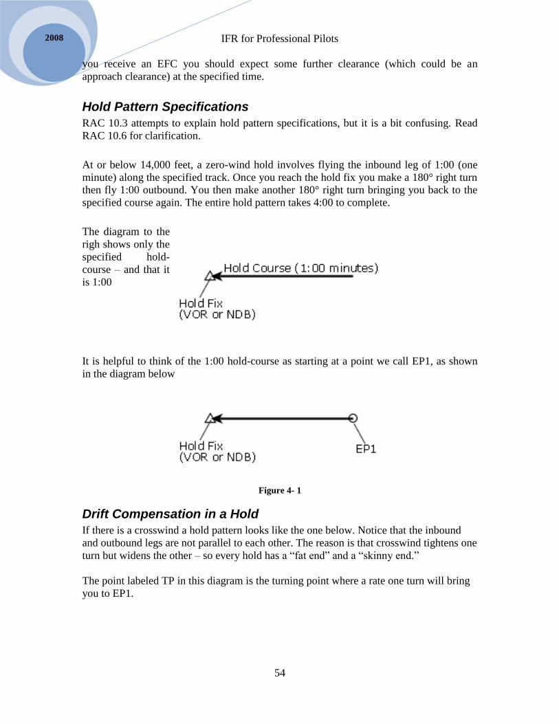
IFR for Professional Pilots
54
2008
you receive an EFC you should expect some further clearance (which could be an
approach clearance) at the specified time.
Hold Pattern Specifications
RAC 10.3 attempts to explain hold pattern specifications, but it is a bit confusing. Read
RAC 10.6 for clarification.
At or below 14,000 feet, a zero-wind hold involves flying the inbound leg of 1:00 (one
minute) along the specified track. Once you reach the hold fix you make a 180° right turn
then fly 1:00 outbound. You then make another 180° right turn bringing you back to the
specified course again. The entire hold pattern takes 4:00 to complete.
The diagram to the
righ shows only the
specified hold-
course – and that it
is 1:00
It is helpful to think of the 1:00 hold-course as starting at a point we call EP1, as shown
in the diagram below
Figure 4- 1
Drift Compensation in a Hold
If there is a crosswind a hold pattern looks like the one below. Notice that the inbound
and outbound legs are not parallel to each other. The reason is that crosswind tightens one
turn but widens the other – so every hold has a “fat end” and a “skinny end.”
The point labeled TP in this diagram is the turning point where a rate one turn will bring
you to EP1.

IFR for Professional Pilots
55
Selair.selkirk.ca
Figure 4- 2
The fat end and the skinny end depend on which way the crosswind is blowing. In the
hold above wind is from the north, in the hold below wind is from the south.
Figure 4- 3
On the hold course compensate for wind exactly as we always do – in other words drift
correction equals crosswind / magic-number.
Drift correction on the outbound leg must be three times the amount used on the
inbound leg if outbound time is 1:00. If outbound time is less than 1:00 (see below) then
outbound drift will be more than three times inbound drift. If outbound time is more than
1:00 then outbound drift will be less than three times inbound drift – but will always be
more than inbound drift.
In Summary:
1. Basic outbound drift is 3 times inbound drift.
2. Outbound drift is more than 3 times if outbound time is less than 1:00

IFR for Professional Pilots
56
2008
3. Outbound drift is less than 3 times if outbound time is more than 1:00
Headwind / Tailwind Compensation in a Hold
With no headwind or tailwind outbound time is basically 1:00 – however it must be
increased slightly if there is a lot of crosswind.
An IMPORTANT rule of thumb is that if the tailwind on the outbound leg equals 1/3 the
TAS the outbound time will be zero. The diagram below shows that in this case a
continuous 360° right turn is made at the fix resulting in a 1:00 inbound leg.
Figure 4- 5
When tailwind is less than 1/3 your TAS proportionally reduce the outbound time. For
example if you hold at 150 KTAS you know that 50 knots of wind would require zero
outbound time so with 25 knots tailwind estimate 30 seconds outbound – etc.
When there is a headwind on the outbound leg the outbound time must be increased.
Headwind of 1/3 TAS requires outbound time of 2:00. Adjust proportionally for lesser
winds.
In summary:
1. Tailwind outbound of 1/3 TAS requires zero outbound time
2. Headwind outbound of 1/3 TAS requires 2:00 outbound time
3. Adjust proportionally for lesser winds.
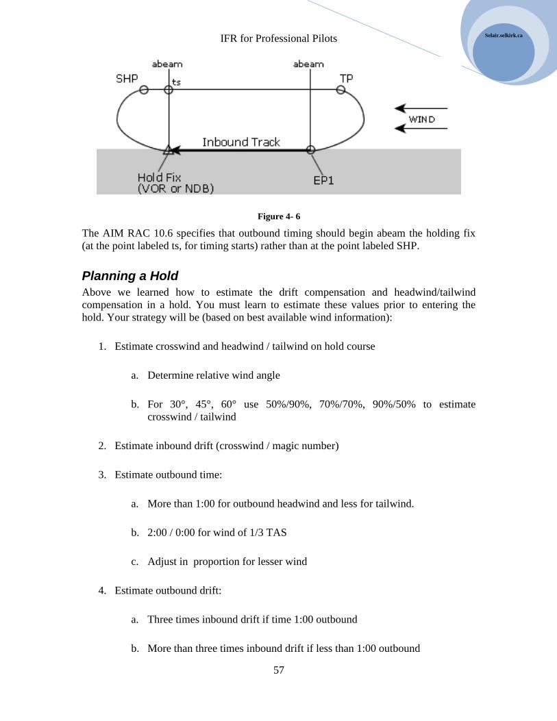
IFR for Professional Pilots
57
Selair.selkirk.ca
Figure 4- 6
The AIM RAC 10.6 specifies that outbound timing should begin abeam the holding fix
(at the point labeled ts, for timing starts) rather than at the point labeled SHP.
Planning a Hold
Above we learned how to estimate the drift compensation and headwind/tailwind
compensation in a hold. You must learn to estimate these values prior to entering the
hold. Your strategy will be (based on best available wind information):
1. Estimate crosswind and headwind / tailwind on hold course
a. Determine relative wind angle
b. For 30°, 45°, 60° use 50%/90%, 70%/70%, 90%/50% to estimate
crosswind / tailwind
2. Estimate inbound drift (crosswind / magic number)
3. Estimate outbound time:
a. More than 1:00 for outbound headwind and less for tailwind.
b. 2:00 / 0:00 for wind of 1/3 TAS
c. Adjust in proportion for lesser wind
4. Estimate outbound drift:
a. Three times inbound drift if time 1:00 outbound
b. More than three times inbound drift if less than 1:00 outbound
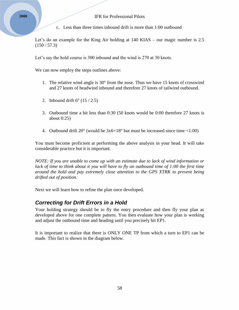
IFR for Professional Pilots
58
2008
c. Less than three times inbound drift is more than 1:00 outbound
Let’s do an example for the King Air holding at 140 KIAS – our magic number is 2.5
(150 / 57.3)
Let’s say the hold course is 300 inbound and the wind is 270 at 30 knots.
We can now employ the steps outlines above:
1. The relative wind angle is 30° from the nose. Thus we have 15 knots of crosswind
and 27 knots of headwind inbound and therefore 27 knots of tailwind outbound.
2. Inbound drift 6° (15 / 2.5)
3. Outbound time a bit less than 0:30 (50 knots would be 0:00 therefore 27 knots is
about 0:25)
4. Outbound drift 20° (would be 3x6=18° but must be increased since time <1:00)
You must become proficient at performing the above analysis in your head. It will take
considerable practice but it is important.
NOTE: If you are unable to come up with an estimate due to lack of wind information or
lack of time to think about it you will have to fly an outbound time of 1:00 the first time
around the hold and pay extremely close attention to the GPS XTRK to prevent being
drifted out of position.
Next we will learn how to refine the plan once developed.
Correcting for Drift Errors in a Hold
Your holding strategy should be to fly the entry procedure and then fly your plan as
developed above for one complete pattern. You then evaluate how your plan is working
and adjust the outbound time and heading until you precisely hit EP1.
It is important to realize that there is ONLY ONE TP from which a turn to EP1 can be
made. This fact is shown in the diagram below.
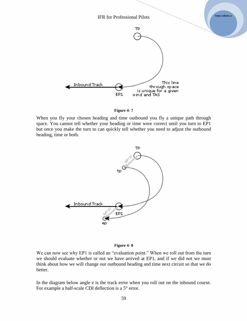
IFR for Professional Pilots
59
Selair.selkirk.ca
Figure 4- 7
When you fly your chosen heading and time outbound you fly a unique path through
space. You cannot tell whether your heading or time were correct until you turn to EP1
but once you make the turn to can quickly tell whether you need to adjust the outbound
heading, time or both.
Figure 4- 8
We can now see why EP1 is called an “evaluation point.” When we roll out from the turn
we should evaluate whether or not we have arrived at EP1, and if we did not we must
think about how we will change our outbound heading and time next circuit so that we do
better.
In the diagram below angle e is the track error when you roll out on the inbound course.
For example a half-scale CDI deflection is a 5° error.
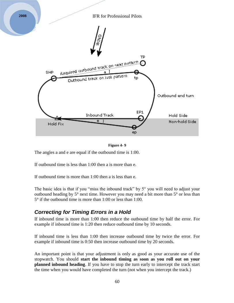
IFR for Professional Pilots
60
2008
Figure 4- 9
The angles a and e are equal if the outbound time is 1:00.
If outbound time is less than 1:00 then a is more than e.
If outbound time is more than 1:00 then a is less than e.
The basic idea is that if you “miss the inbound track” by 5° you will need to adjust your
outbound heading by 5° next time. However you may need a bit more than 5° or less than
5° if the outbound time is more than 1:00 or less than 1:00.
Correcting for Timing Errors in a Hold
If inbound time is more than 1:00 then reduce the outbound time by half the error. For
example if inbound time is 1:20 then reduce outbound time by 10 seconds.
If inbound time is less than 1:00 then increase outbound time by twice the error. For
example if inbound time is 0:50 then increase outbound time by 20 seconds.
An important point is that your adjustment is only as good as your accurate use of the
stopwatch. You should start the inbound timing as soon as you roll out on your
planned inbound heading. If you have to stop the turn early to intercept the track start
the time when you would have completed the turn (not when you intercept the track.)

IFR for Professional Pilots
61
Selair.selkirk.ca
Figure 4- 10
If you “miss” the inbound track you will of course have to correct track. This will result
in a “snaky course” to the hold fix, as shown above. The result is extra time which will
throw off your timing. You should think about this.
Time and Heading Corrections Interact
As you know, outbound drift correction depends on outbound timing. Thus you must
remember that as you correct the timing in your hold you will also have to adjust the drift
correction. The diagram below helps you visualize why. It shows that if you reduce
outbound time you must increase drift correction. It also shows that if you increase
outbound time you must reduce drift correction.
Figure 4- 11
Consistency is the Key to Good Holding Patterns
Consistency of the turns in a holding pattern is crucial to establishing the hold. If you use
a different angle of bank each time around you will never establish the hold. If you use
the autopilot it will make every turn the same and you will have a very consistent hold.
When you hand fly the hold you must strive to be equally consistent.
IFR for Professional Pilots
62
2008
Hold Entries
Now that we have thoroughly discussed the factors that go into maintaining a holding
pattern we will discuss how to enter the hold.
Step one is always to track directly to the hold fix.
While enroute to the fix you should plan the hold as described above.
RAC 10.5 specifies the three types of hold entry procedures that are permitted. RAC 10.5
implies that these procedures are compulsory and you should treat them as such.
Hold entries are the most commonly failed item on the initial IFR flight test – so pay
close attention to this topic. You should read Instrument Procedures Manual section
4.4.4, which gives a very good verbal description of the three hold entry procedures. The
three hold entry procedures are:
1. Direct
2. Parallel
3. Offset (teardrop)
It is VERY strongly recommended that you silently describe to yourself the procedure
you will follow in the minute or so prior to entering a hold. Your description should be a
word for word repeat of the description in Instrument Procedures Manual 4.4.4. For
example if you are about to complete a parallel hold entry you say to yourself “this will
be a parallel entry. Upon reaching the fix I will turn left to heading _______ for 1:00. I
will then turn left to intercept inbound track _______. On second arrival over the fix I
will turn right …”
If you will take the time to explicitly describe the hold entry procedure to yourself just
before flying it, especially including the words left and right as regards each turn, you are
quite likely going to do fine and will pass your IFR ride. If you refuse to do this you may
very well make one of the classic mistakes. For example many people turn right rather
than left for the second turn – in the quote above the offending turn is in bold print.
Unfortunately if you turn the wrong way on your IFR ride you will have to come back
another day and try again. If you do it on a real IFR flight you should simply continue to
the hold fix and continue by making a direct hold entry.
In your Instrument Procedures Manual section 4.4.5 you will note that non-standard holds
can be either left turn holds or holds with timing other than 1:00 (or 1:30 above 14,000’.)
As an assignment prepare for yourself a verbal description of each of the three hold entry
procedures for the case of a hold with left turns. When you have completed the
assignment commit your three descriptions along with the ones in Instrument Procedures
Manual 4.4.4 to memory so that you can say them to yourself whenever needed without
any hesitation. Don’t even consider going further with this text and for sure don’t get into
an airplane to fly a holding pattern if you can’t quote these hold entry descriptions
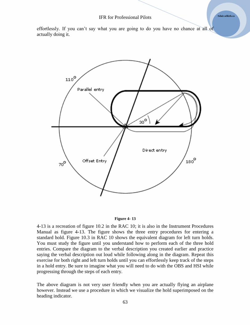
IFR for Professional Pilots
63
Selair.selkirk.ca
effortlessly. If you can’t say what you are going to do you have no chance at all of
actually doing it.
Figure 4- 13
4-13 is a recreation of figure 10.2 in the RAC 10; it is also in the Instrument Procedures
Manual as figure 4-13. The figure shows the three entry procedures for entering a
standard hold. Figure 10.3 in RAC 10 shows the equivalent diagram for left turn holds.
You must study the figure until you understand how to perform each of the three hold
entries. Compare the diagram to the verbal description you created earlier and practice
saying the verbal description out loud while following along in the diagram. Repeat this
exercise for both right and left turn holds until you can effortlessly keep track of the steps
in a hold entry. Be sure to imagine what you will need to do with the OBS and HSI while
progressing through the steps of each entry.
The above diagram is not very user friendly when you are actually flying an airplane
however. Instead we use a procedure in which we visualize the hold superimposed on the
heading indicator.

IFR for Professional Pilots
64
2008
Figure 4-14
Always set the HSI Course Bar to the inbound hold course. Then look at the tail of the
HSI Course Bar. The tail will be in one of the following sectors. This determines the hold
entry.
Figure 4- 15
It is important to remember that you must look at the tail of the HSI Course Bar. A
common error is to look at the head (arrow end) of the course bar, which results in the
wrong entry procedure.

IFR for Professional Pilots
65
Selair.selkirk.ca
Difficult Hold Entries
Some hold entries are more difficult than others. The most difficult hold entry is a direct
entry when the angle of approach to the hold fix is near the parallel entry limit.
Momentum is the problem, as shown in the diagram below.
Figure 4- 16
When making a direct entry in the situation above you make a right turn to the outbound
heading but you should apply several degrees of drift correction and observe your GPS
cross-track distance. At the end of the outbound leg cross-track distance should be
approximately 1% of TAS.
DME Holds
Compared to the extensive discussion above DME holds are very simple. RAC 10.8
explains DME holds. A typical DME hold clearance might be “cleared to the 10 DME fix
to hold west on the 270-degree radial between 10 and 15 DME; maintain 7,000, expect
further clearance at ________.) The hold is represented in 4-17. A DME hold has a hold
fix, as do all holds but it also has an outbound fix, as shown in the figure below. The
outbound leg ends at the outbound fix, NOT after any particular amount of time.

IFR for Professional Pilots
66
2008
Figure 4- 17
Note that DME holds can be any length that ATC assigns. The example hold is five
nautical miles long which is about twice as long as a the usual hold conducted by a
general aviation airplane holding in the 100 to 150 knot speed range. As a result
outbound time is much more than 1:00 and therefore outbound drift is much less than
three times inbound drift.
Intersection Holds
Intersection holds are quite common in STARs. When traffic backs up, perhaps due to
runway plowing or an unexpected runway closure you will often be assigned a hold at an
intersection along the arrival route.
Almost always the hold entry is direct, but it is possible to have other entries, as shown in
the diagram below.

IFR for Professional Pilots
67
Selair.selkirk.ca
Of course, with GPS you could arrive at the intersection in any direction and do any hold
entry.
GPS Use In Holds
An IFR certified GPS could be used to hold at any VOR, NDB or intersection. Optionally
the underlying navaids can be tuned and most pilots will take this option.
When holding using GPS there is no fundamental difference in the procedure you use.
The shape of the holding pattern will be exactly the same – i.e. the wind drift and timing
rules covered above apply regardless of the navigation equipment you are using. The
difference lies in the amount and type of information available to the pilot much of which
can make holding a lot easier. Each manufacturers GPS system is different but almost all
provide the following information:
Instantaneous groundspeed (not closing speed) with no slant range error
Drift angle
Cross-track distance
Wind direction and speed
Precise groundspeed readout is obviously very useful in a hold. Be sure to compare the
groundspeed inbound and outbound and use it to improve your initial estimate of the
outbound time. Do this during the entry procedure.
Cross-track distance is the distance between the selected track and the airplanes present
position measured at right angles. In zero wind the outbound track is 1% of TAS from the
inbound track.

IFR for Professional Pilots
68
2008
When there is a crosswind the “skinny end” of the hold is less than 1% TAS and the “fat
end” is more than 1%. Get to know the 1% value for your airplane. For example, this
would be 1.5 NM in the King Air and 1.2 NM in the Beech 95. Expect the fat end and
skinny end to be a bit more and less than this.
IFR for Professional Pilots
69
Selair.selkirk.ca
Chapter 8 Arrivals
Read all of RAC 9.0 before proceding
ATIS
Get the ATIS good and early – it is never too early to check ATIS.
When single pilot set ATIS volume low enough that you can still hear calls from ATC.
The Altimeter setting the controller gives you when clearing you for the approach takes
precedence over the ATIS value.
When contacting arrival control tell them which ATIS you have. A typical call would be
“Vancouver Arrival this is B95 GSAK level 4000, with ATIS information November.”
STARs
STARs have been discussed under flight planning and will be mentioned again in the
next chapter on approaches.
Read RAC 9.2 very carefully.
STARs can be drawn directly from the GPS database and this is the method you should
use – even for conventionally STARs (it is compulsory for RNAV STARs.)
Make sure you know how to “close” the STAR using the GPS. For the GNS430 and
KLN90b GPS you will need to use the Direct button as you arrive at the DTW. Be sure
you know how to do it.
It is critical the PNF learn to examine the GPS flight plan and check all bearings and
distance as soon as an arrival has been loaded.
TIP: you can load an arrival and then activate once cleared for it (on the GNS430.)
Descent out of Controlled Airspace
Read RAC 9.4
Advance Notice of Intent in Minimum Weather
RAC 9.5
IFR for Professional Pilots
70
2008
This is an important time saving procedure in IFR flying. Let the arrival controller know
what your plan is in the event of a missed approach.
Contact and Visual Approaches
The definition of Visual Approach has been updated. Be sure to read RAC 9.6.2
carefully.
When Jazz arrives in Castlegar via the Arrow Lakes is that a Contact approach or a
Visual approach?
Radar Arrivals
Read RAC 9.7.
ATC expects you to slow to your normal operating speed when on vectors to an
approach. You don’t need special permission for this.
On vectors you should not expect to hear the words “cleared for the …. Approach” until a
few seconds prior to intercepting the final approach course. Never-the-less you should
have all checks complete and the airplane configured just as you would in a procedure
turn.
ATC may sometimes ask you to slow down or keep your speed up in order to fit you in
with other traffic. Such requests are always made prior to being “cleared for the
approach.” Once you are cleared for the approach the speed restriction is cancelled.
Initial Radio Contact with Control Towers
Read RAC 9.8
Notice that there is a difference in procedure if you are vectored to final as opposed to
being cleared for a full procedure. When cleared for a full procedure you are supposed to
give your ETA for the IAF – if vectored to final you do not.
For example, “Abbotsford Tower B95 GSAK has been cleared for the full procedure ILS
RWY 07 approach, estimating the Abbotsford beacon in 4 minutes. We have ATIS
Whiskey.”
On vectors to final you would simply say, “Vancouver Tower B95 GSAK on the ILS
26L, with ATIS Whiskey.”
At controlled airports, after the above, you only need to report at locations requested by
the tower.
IFR for Professional Pilots
71
Selair.selkirk.ca
Take note of RAC 9.10, which explains that the tower controller may take control of you
on final in VMC conditions and thereafter you will not have the usual traffic separation.
Radio calls: at Uncontrolled Airports
Read RAC 9.11
Normally the IFR controller will hand you over to the MF/ATF well before you get to the
airport. If they don’t you should use your second radio to call ahead and make the
required MF/ATF calls.
The required reports – at a minimum – are:
1. Five minutes before starting the approach – state the expected landing time
2. Outbound if conduction a procedure turn or at the IF when conducting a straight-
in approach.
3. At the FAF – or three minutes before landing if there is no FAF
4. On Final
5. When commencing circling
6. Upon commencing a missed approach
It is important to remember that IFR aircraft must conform to the active circuit when
there is VFR traffic.
Cold Temperature Corrections
Read RAC 9.16 and 9.17
The procedure for cold temperature corrections is explained in the textbook “Navigation
for Professional Pilots.
You should read carefully the instructions in the CAP GEN or RAC 9.16 and always do
your calculations as per the examples.
Remote Altimeter Settings
Read RAC 9.17.2

IFR for Professional Pilots
72
2008
Not all airports have an altimeter setting available. If a particular airport does not have an
altimeter setting then the approach plate will tell you which altimeter setting to use and
the MDA will take that into account so no correction is required on your part.
At many airports the altimeter setting is not available after a certain hour in the day. In
this case the approach plate will tell you which altimeter setting to use and provide a
correction factor to apply such as “ add 200 feet to all procedure altitudes when using xxx
altimeter setting.” It is quite common to also find the note that circling minima apply –
which means that you are NOT authorized to use the straight-in approach minima.
Approach Ban
Read RAC 9.19.
Takeoff minima were covered in Chapter 5
The approach ban rules are quite complex – you will study them in Air Regs. The rules
for General Aviation operators are quite simple – and that is what you will be during your
flight training (9.12.2.2.) However, as soon as you graduate and become a commercial
pilot you will need to know the commercial operator rules.
We operate the Alsim as though we are under 9.16.2.3 most of the time – so get to know
this section very well.
RAC 9.19.2.5 covers commercial operators will an Ops Spec. On some Alsim flights we
will simulate operation under these rules, so compare them to the ones for operators
without an Ops Spec and notice the difference.
On the IFR ride candidates often fail to take note of 9.19.2.6 and 9.19.2.7 – so read this
and consider it carefully.

IFR for Professional Pilots
73
Selair.selkirk.ca
Chapter 9 Approaches
Start by reading RAC 6.5. This explains that all approaches in Canada are designed
according to rules in TP308. Our rules are almost identical to USA rules, which they call
TERPS. Therefore, what you learn in Canada will serve you will when flying in the USA.
Before reading what follows read all of RAC 9.0 (IFR Arrival Procedures). Once you
have read this you will know all the rules about things such as contact and visual arrivals,
what to say to the tower when handed of by Center, etc, etc.
Before reading what follows completely read your CAP GEN ensuring that you know
how to interpret an approach plate. You should know how to interpret all the symbols on
the approach charts. Even more important you should be able to locate all the minimum
altitudes on the approach plate. You should also be able to find items such as the type of
approach lighting, runway dimensions, etc. Interpretation of approach plates will not be
covered in this text.
Types of IFR Approaches
You will learn to perform 8 types of IFR approaches:
1. ILS (Cat 1)
2. PAR
3. ADF
4. VOR
5. Localizer
6. Back course
7. RNAV (GNSS)
8. GNSS Overlay
All the above IFR approaches are designed to “get you out of cloud” so you can land
visually. You will fly the procedure and if the weather is good enough you will see the

IFR for Professional Pilots
74
2008
“required visual reference”, at the end of the procedure. The descent for landing is a
visual maneuver.
The concept of required visual reference is a key to IFR approaches. It is explained in
RAC 9.19.3. Be sure to read and memorize the list of visual references.
At the missed approach point on the approach, if you do not see the required visual
reference you conduct a missed approach and go to your alternate.
It is particularly important to know which of the potential visual references are available
on the approach you are flying. The lower right corner of every approach plate has a
miniature airport diagram that shows the approach lights available. Be sure to examine it
as you prepare for your approach. You will need to know the approach light codes, which
are in your CAP GEN and also the CFS.
Approach Ban
In order to improve safety Transport Canada introduced a comprehensive approach ban in
recent years. Prior to the approach ban for the most part pilots were permitted to fly IFR
approaches regardless of reported weather to determine whether or not the required visual
reference could be achieved. Many pilots chose to fly approaches even when the reported
weather made it quite obvious there was no possibility of achieving the required visual
reference. The approach ban regulations now prohibit making approaches in poor
visibility, which should improve safety.
Unfortunately the regulations that have evolved are extremely cumbersome and complex
– so you will just have to suck it up and learn the rules. The rules are explained in RAC
19.19. 2 and are also in the CAP GEN.
There are three distinct sets of approach bans:
1. General Aviation Approach Ban (applies to you during flight training)
2. Commercial Operators Approach Ban – with no OPS SPEC
3. Commercial Operators Approach Ban – with an OPS SPEC
You will learn about OPS SPECS for commercial operators in your air regulations
course. Eventually you will have to know all the approach ban limits. In the Alsim we
will simulate operations for a Commercial Operators Approach Ban – with no OPS
SPEC, in the BE95 we are General Aviation Operators.

IFR for Professional Pilots
75
Selair.selkirk.ca
Precision vs. Non-Precision Approach Approaches with vertical guidance, i.e. glide-path are called precision approaches. This
includes ILS and PAR approaches. LPV and VNAV approaches are a new type of “near”
precision approach based on GNSS.
All other approaches have no glide-path. These approaches are classified as non-
precision: (ADF, VOR, Localizer, Back course, and RNAV (GNSS) / LNAV.) The pilot
performs descent in steps through a series of safe altitudes.
Straight-in vs. Circling (Naming Conventions)
Most IFR approaches line up with a runway so that at the end of the approach you can
land on the runway (if winds and weather permit.) This is indicated in the procedure
name, for example:
NDB RWY 25
The above is an NDB approach that leads to landing on runway 25
VOR RWY 07
The above is a VOR approach that leads to landing on runway 07.
NDB A
The above is an NDB approach that DOES NOT position the airplane for landing on a
specific runway. This is referred to as a “circling approach” which means that a visual
circling procedure must be done to align with a runway for landing after the IFR
approach is complete. Circling procedures are indicated with a letter following the
approach name, for example VOR C or LOC/DME E, etc.
There are very specific criteria that must be met for an approach to be considered
“straight-in” these are given in RAC 9.22 – make sure you know them.
Circling criteria are given in RAC 9.23 – be sure to read and understand them. For
example a category B airplane must remain within 1.5NM of the runways, and a category
C airplane (Alsim) must remain within 1.7NM. Note that the published circling MDA
provides 300 feet of terrain clearance within the circling airspace.
Circling restrictions are quite common. These are shown on approach plates. For example
look at the NDB B approach in CYCG and notice “No Circling” to the east of the airport.
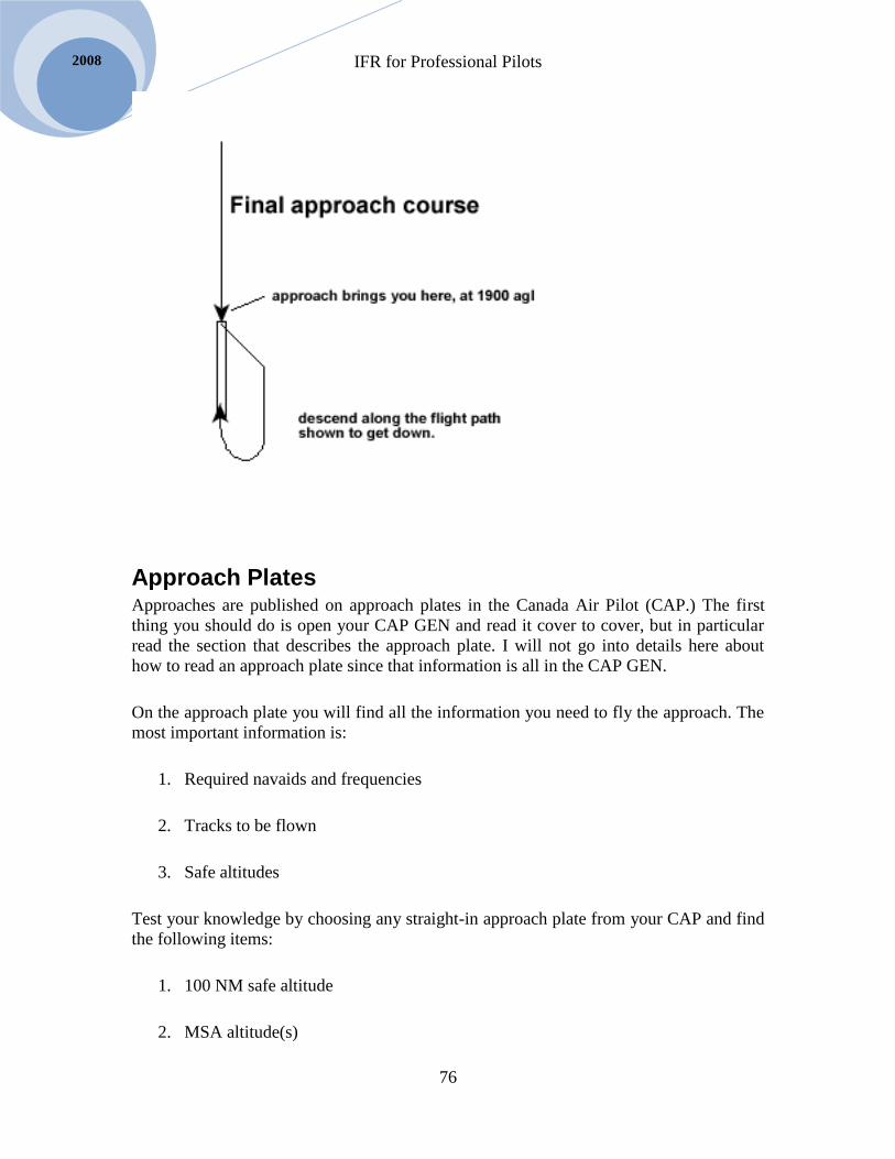
IFR for Professional Pilots
76
2008
Approach Plates Approaches are published on approach plates in the Canada Air Pilot (CAP.) The first
thing you should do is open your CAP GEN and read it cover to cover, but in particular
read the section that describes the approach plate. I will not go into details here about
how to read an approach plate since that information is all in the CAP GEN.
On the approach plate you will find all the information you need to fly the approach. The
most important information is:
1. Required navaids and frequencies
2. Tracks to be flown
3. Safe altitudes
Test your knowledge by choosing any straight-in approach plate from your CAP and find
the following items:
1. 100 NM safe altitude
2. MSA altitude(s)

IFR for Professional Pilots
77
Selair.selkirk.ca
3. Navaid the MSA altitudes are based on
4. Intermediate approach course
5. Approach course
6. Procedure turn altitude
7. FAF crossing altitude (non-precision approach) or GP check altitude (ILS)
8. MDA (non-precision approach) or DH (ILS)
9. Circling MDA
10. Recommended visibility to complete the approach
11. Runway elevation
12. Type of approach lights available
13. Missed approach procedure
You should flip through your CAP and make sure you can quickly find each of the above
items on every plate. You will soon notice that they are always found in the same location
on each plate and thus easy to find.
The above list asks you to find items in approximately the order you will need them as
you fly an approach.
Approach Segments
Approaches are broken into four segments:
1. Initial segment
2. Intermediate segment
3. Final segment
4. Missed approach procedure
On rare occasion you will find an approach that does not have a final segment. The other
three segments are always there.
IFR for Professional Pilots
78
2008
It is important to keep track of which segment you are in. Each segment has a safe
altitude(s) and a purpose. Therefore, knowing what segment you are in will clue you in as
to whether you should slow down, do before landing checks, extend gear etc.; but most
importantly it tells you what your safe altitude is.
Definitions: IAF, IF, FAF, MAP
The initial approach segment begins at the Initial Approach Fix (IAF) and ends at the
Intermediate Fix (IF)
The intermediate segment begins at the IF and ends at the Final Approach Fix (FAF)
The final segment begins at the FAF and ends at the Missed Approach Point (MAP)
The missed approach procedure begins at the MAP.
In summary:
1. Initial Segment – from IAF to IF
2. Intermediate Segment – from IF to FAF
3. Final Segment – from FAF to MAP
4. Missed approach procedure – starts at MAP
The FAF is indicated by the Maltese cross symbol on approach plates. It is a critical
location so you must learn to identify it. On rare occasion you will find an approach plate
that does not have a FAF. In this case there is no final segment, in other words the
Intermediate segment ends at the MAP and the approach goes from intermediate segment
directly to missed approach procedure.
The IF symbol appears on some approach plates and not on others. If not published the IF
is by definition on the intermediate course at the distance from the FAF specified for the
procedure turn. Take the NDB/NDB A approach to Penticton for example. The IF is not
published but it is on the course 162 to UNT at 12NM from YYF beacon, or 14.1DME
(CH 40). This information is found at the lower left corner of the profile section of the
approach plate.
The MAP has no specific symbol but it is indicated by a combination of the profile
diagram and the written missed approach procedure. Referring again to the NDB/NDB A
approach to Penticton the MAP is at the YYF beacon (2.1 DME).

IFR for Professional Pilots
79
Selair.selkirk.ca
On most approaches the MAP is directly above the threshold of the runway, but not
always. So read the plate carefully and know where the MAP is.
When an approach plate includes a transition such as a track to the IF or a DME arc
leading to the IF there will be a published IAF where the transition begins. If no transition
is published the IAF is where the procedure turn starts and 99% of the time this is the
same as the FAF. On vectors there is no IAF, as explained below.
Initial Segment
The purpose of the initial segment is to:
1. Align the airplane for entry into the intermediate segment.
2. Slow to approach speed and configure as required
Initial segments fall into two broad categories:
1. Radar vectored arrival
2. Pilot navigation
a. Procedure turn
b. DME arc
c. Transition
d. STAR (can be “conventional” or RNAV)
Vectored Arrival
When you are radar vectored to an approach there is no IAF, so consider yourself in the
initial segment as soon as the controller begins vectoring you.
In the initial segment you should slow to your desired approach speed and complete
appropriate checklists (Before Landing in BE95 and Approach Checklist will already be
done in King Air.)
Radar arrivals are described in RAC 9.7.1 – read this material fully.
Some approaches are now published that require radar arrival – i.e. a procedure turn is
not authorized. Several approaches to CYVR and CYPK are examples of this. Please
examine these approach plates to see how the restriction is indicated.

IFR for Professional Pilots
80
2008
Expect the final vector (the one that intercepts the intercept Intermediate Segment) to
result in a 30° to 45° intercept angle to final. The controller normally vectors you to a
symbol on the radar scope known as the “gate.” The gate is located on the intermediate
segment, inside the IF, where you will be below the glidepath on an ILS (or equivalent
location on a non-precision approach.) In some cases the controller will vector you to a
“short gate” which is a point closer to the FAF such that you may require a greater than
normal descent rate, i.e. you may be above the glidepath when you intercept the
intermediate segment.
RAC 9.7.3 talks about speed restrictions on a vectored arrival. This material is important.
You MUST slow down to an appropriate speed during your vectors (don’t expect ATC to
tell you when to slow down.) ATC expects you to fit in with other traffic, so flying
unusually fast or slow will create problems. Your SOP speeds have been chosen to meet
most ATC needs, but you might be asked to speed up or slow down a bit to fit with other
traffic. You don’t want to slow down either too early or too late, so it is very important to
have a sense of how far you are from the gate; to do that setup the GPS with the FAF as
the active waypoint and with OBS mode selected. The moving map will orient you to the
vectors. Vectors are simply like a large circuit with a downwind and base leg of about 10
miles (i.e. 10 times larger than a VFR circuit.) You should be slowed to 120 KIAS in the
BE95 or 140KIAS in the King Air prior to the gate.
Critical Point: You MUST NOT descend from the assigned vectoring altitude until
established on the intermediate segment. You may be tempted to descend early when
being vectored to a short-gate – but you must wait until you are established on the
intermediate approach course before descending.
When vectored to a normal gate you intercept the intermediate course and then a few
seconds later intercept the glidepath and then descend. It is worth knowing that your
autopilot / flight director will only couple-up for an ILS approach in this order. I.E.
localizer must couple before glidepath couples. If the flight-director encounters the
glidepath before the localizer it will simply fly through it.
Short-Gate
The controller normally vectors the airplane onto final at a point called the “gate”, which
is far enough from touchdown that the airplane is below the 3° glidepath. When this
happens you will typically have several seconds after intercepting final before
intercepting the glidepath, at which point you extend the gear and start your approach
(more on that later).
Sometimes controllers vector airplanes inside the gate. This is called a “short gate” (the
gates are symbols shaped like a > on the controller’s radar screen that s/he vectors the
airplane to). At some airports there is a standard gate and a short gate. On a short gate the
controller vectors the airplane where it may be on or even above the glidepath when it
intercept final. In this case you will feel compelled to quickly extend the gear and start
final descent. Be careful not to descend too soon. DO NOT descend until you are
established on final, even if the glidepath needle is alive. On vectors to an NDB approach
IFR for Professional Pilots
81
Selair.selkirk.ca
be especially careful because there will be bank error as you turn final; don’t descend
until you complete the turn and confirm you are within 10° of final approach track.
Procedure Turns
The term “full procedure approach” means that a procedure turn is to be done.
The first step is to fly to the IAF. For an NDB approach this will be the beacon, for a
VOR approach it will be the VOR. For an ILS approach there is often an NDB at the IAF
you can fly directly to. (Notice that 99% of the time the IAF and FAF are in the same
place – but there are lots of exceptions where the FAF for example is at a particular DME
from the VOR).
The diagram below is from TP308, which is the Transport Canada publication describing
IFR approach design criteria. It shows the shape and size of the procedure turn airspace.
You should be familiar with the following points about this airspace:
There is an “entry area” marked with hash marks in the diagram
The Primary area extends from 6 to 8 NM laterally from the inbound course on
the “maneuvering side”
The Primary area extends 4NM laterally on the “non-procedure side”
There may be a higher safe altitude in the entry area than in the Primary area in
some cases

IFR for Professional Pilots
82
2008
In the Diagram above the point labeled “FIX” is the IAF. As you fly to the IAF you
descend through a series of safe altitudes. In some cases your route to the IAF may be
along an airway in which case you should descend to the airway MEA. If your route to
the IAF is off airway you can descend to the 100NM safe altitude until within the 25NM
MSA and then descend to the MSA altitude.
Upon reaching the IAF there are four types of procedure turn you can do:
1. Standard PT
2. S-turn PT
3. Modified-racetrack PT
4. Racetrack PT
Each of these procedure turns is designed to keep you within the designated procedure
turn airspace.
Once past the IAF you can start your descent to the entry zone altitude. You should report
“by the ______ outbound” once you are abeam or over the IAF and headed away from
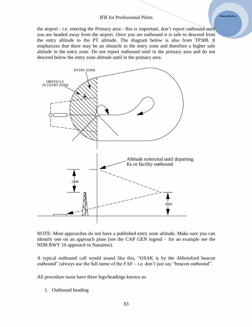
IFR for Professional Pilots
83
Selair.selkirk.ca
the airport - i.e. entering the Primary area - this is important, don’t report outbound until
you are headed away from the airport. Once you are outbound it is safe to descend from
the entry altitude to the PT altitude. The diagram below is also from TP308. It
emphasizes that there may be an obstacle in the entry zone and therefore a higher safe
altitude in the entry zone. Do not report outbound until in the primary area and do not
descend below the entry zone altitude until in the primary area.
NOTE: Most approaches do not have a published entry zone altitude. Make sure you can
identify one on an approach plate (see the CAP GEN legend – for an example see the
NDB RWY 16 approach to Nanaimo).
A typical outbound call would sound like this, “GSAK is by the Abbotsford beacon
outbound” (always use the full name of the FAF – i.e. don’t just say “beacon outbound”.
All procedure turns have three legs/headings known as:
1. Outbound heading

IFR for Professional Pilots
84
2008
2. 1st procedure turn heading (1
st PT HDG)
3. 2nd
procedure turn heading (2nd
PT HDG)
Open your CAP to any approach
plate that has a procedure turn on it.
You must learn to identify the three
PT legs listed above – this is very
easy to do.
The diagram to the left is typical of
an approach plate:
1. Outbound heading = 225°
2. 1st PT heading = 180°
3. 2nd
PT heading = 360°
Procedure turn are designated as left or right depending on whether the 1st PT heading is
45 left or right of the outbound heading. The example above is a left procedure turn.
The diagram to the left shows an IAF at the
center. You would fly directly to the IAF
and perform the type of procedure turn
shown in each of the four sectors shown.
The S-turn is always used when approach
from the “procedure side.” The diagram
shows a right procedure turn so the S-turn
sector is in the location shown. If this had
been a left procedure turn the S-turn and
modified racetrack sectors would swap.
The standard and racetrack sectors are the
same for left and right procedure turns.
The above diagram is important but rather difficult to use in flight. Just as with holds we
need a procedure that allows us to visualize the type of procedure turn on the heading
indicator or HSI.

IFR for Professional Pilots
85
Selair.selkirk.ca
As you fly toward the IAF set
the track bar on the HSI to the
approach course, as shown to the
left.
The outbound heading always
goes on the tail of the HSI.
Notice the 45° markings on the
HSI, in the diagram to the left I
have circled them to highlight
them.
You judge the type of procedure
turn depending on where the tail
of the track bar is – as shown
below.
If the tail of the track bar is
within 45° of the nose do a
standard procedure turn.
If the tail of the track bar is
within 45° of the tail do a
racetrack procedure turn.
If the tail is to the side - between
the 45° marks - you will either
do an S-turn or a modified
racetrack depending on where
the 1st PT heading is. If the 1
st
PT heading is below the track
bar do an S-turn – if it is above
the track bar do a modified
racetrack.
The order that the legs are flown in varies depending on the type of procedure turn. We
will now go through each type of procedure turn.
Standard Procedure Turn
For a standard procedure turn:

IFR for Professional Pilots
86
2008
1. Fly outbound first – in this case don’t just fly the heading, track outbound along
the intermediate course.
2. Then, turn to the 1st PT heading and fly it for 1:00 minute.
3. Then turn 180° to the 2nd
PT heading. This turn is always made away from the
FAF – i.e. so that distance from FAF increases in the turn.
The approach plate specifies the maximum distance for the procedure turn. Make sure
you don’t go out too far. On the other hand, you must go out far enough that you will
have enough room to descend in the intermediate segment.
S-Turn Procedure
A generic S-turn looks like the diagram below:
The diagram to the left shows the
HSI when tracking directly to an
IAF prior to an S-turn.
The first turn is always toward the
tail of the HSI, i.e. toward the
outbound heading. The steps are
listed below.

IFR for Professional Pilots
87
Selair.selkirk.ca
1. Turn outbound to the 1st PT heading. Wait until crossing the approach course then
fly 1:00 additional minute.
2. Turn to the outbound heading (with a wind drift correction to maintain a suitable
XTRK). Fly the outbound heading until a suitable distance from the FAF.
3. Turn to the 2nd
PT heading and fly it until intercepting the approach course.
Observing GPS XTRK during step 2 is very useful. XTRK must be a bit more than 1% of
your TAS.
Don’t go outbound beyond the maximum procedure turn distance – BUT, do go outbound
far enough to lose the required altitude in the intermediate segment; on an ILS that means
be below the glidepath.
Modified Racetrack Procedure
A generic modified racetrack looks like the diagram below:
Notice that the three legs are flown in the same order as for the S-turn; the only difference
is that the airplane arrives at the IAF from the non-procedure side, thus it is a shorter turn
to the 1st procedure turn heading and the 1:00 timing starts right away.
The steps for a modified racetrack are:
1. Turn toward the outbound heading rolling out on the 1st PT heading. Fly this
heading for up to 1:00 (check GPS XTRK).
2. Turn to the outbound heading (with a wind drift correction to maintain a suitable
XTRK). Fly the outbound heading until a suitable distance from the FAF.
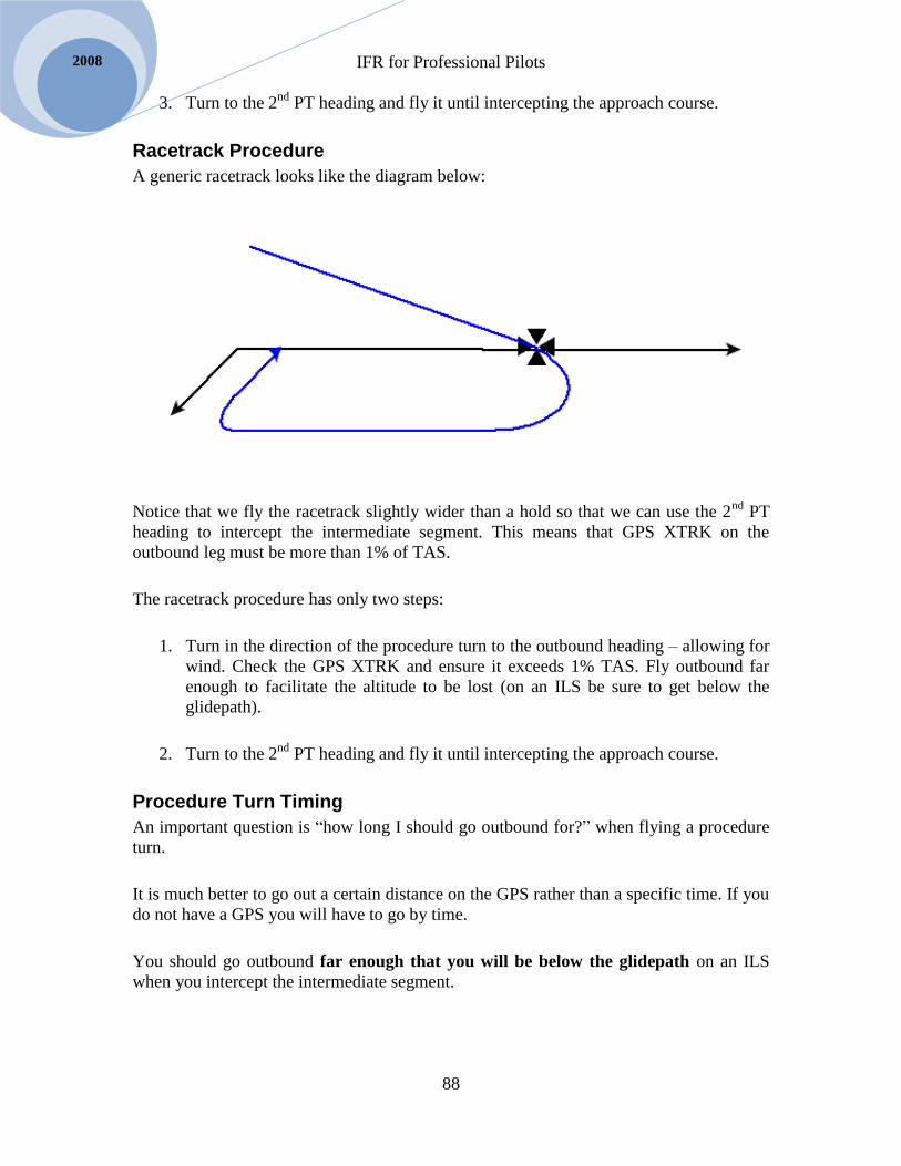
IFR for Professional Pilots
88
2008
3. Turn to the 2nd
PT heading and fly it until intercepting the approach course.
Racetrack Procedure
A generic racetrack looks like the diagram below:
Notice that we fly the racetrack slightly wider than a hold so that we can use the 2nd
PT
heading to intercept the intermediate segment. This means that GPS XTRK on the
outbound leg must be more than 1% of TAS.
The racetrack procedure has only two steps:
1. Turn in the direction of the procedure turn to the outbound heading – allowing for
wind. Check the GPS XTRK and ensure it exceeds 1% TAS. Fly outbound far
enough to facilitate the altitude to be lost (on an ILS be sure to get below the
glidepath).
2. Turn to the 2nd
PT heading and fly it until intercepting the approach course.
Procedure Turn Timing
An important question is “how long I should go outbound for?” when flying a procedure
turn.
It is much better to go out a certain distance on the GPS rather than a specific time. If you
do not have a GPS you will have to go by time.
You should go outbound far enough that you will be below the glidepath on an ILS
when you intercept the intermediate segment.

IFR for Professional Pilots
89
Selair.selkirk.ca
On a non-precision approach there is no glidepath, but you should go outbound far
enough that you would be below the glidepath if it did exist. If you don’t you will have
to descend extra quick or else you won’t reach MDA in time.
The diagram below (from TP308) shows the intermediate segment and its relationship to
the procedure turn airspace. From this you can see that you must NOT descend below the
procedure turn altitude until established on the intermediate course and within the
procedure turn distance from the FAF.
There is a lot of variability between approaches in terms of how much altitude must be
lost in the intermediate segment. It can vary from zero to 2,500 feet. If there is a lot of
altitude to loose in the intermediate segment it is important to notice that when you
review the minima prior to the approach and plan to go out further in the procedure turn
and possibly a greater than normal descent rate. You must NOT go outbound beyond the
procedure turn distance published on the approach plate.
DME ARC Arrival
An alternative to a procedure turn in a DME arc. An arc can often bring an airplane from
the enroute phase of flight to the IF quicker and smoother than a procedure turn. They are
used quite often in areas where radar service is inadequate for vectored arrivals.
The arc normally has a starting point which is the IAF. You can often fly directly to the
IAF using your GPS. If you do not have a GPS you will have to navigate to the IAF using
conventional navaids (i.e. do a PDT and track to the IAF).
The procedure for flying a DME arc is covered in Navigation for Professional Pilots and
will not be fully repeated here. The main points to remember when arcing are these:
IFR for Professional Pilots
90
2008
Radius of a rate-one turn is ½% of TAS. Use this to judge when to start turning to
intercept the arc.
On the arc the RMI needle must be near the wingtip – therefore calculate initial
arc heading by looking at your RMI and adding or subtracting 90 as appropriate.
On the arc DME closing speed should be near zero – but your arc will actually be
a series of short straight legs along which closing speed will first decrease then
increase.
When closing speed is decreasing (as you fly a steady heading) you are getting
closer over time.
When closing speed is increasing (as you fly a steady heading) you are moving
away from the station.
When flying an arc arrival always set the HSI to the final approach course. If you have a
standard VOR indicator put it on the lead radial.
Most arcs intersect the approach course at approximately 90°. But this is not always the
case. When the arc intersects the approach course at a large angle a lead radial is
published on the approach plate. The lead radial provides 2NM “warning” that you are
about to intercept the approach. Shortly after passing the lead radial you should stop
arcing and turn to intercept the approach at a 45° angle.
Transition for Straight-in Arrival
Previously we learned that many approach plates have a published intermediate fix (IF.)
In many cases you can simply fly to the IF and then turn inbound, without the need for
any procedure turn.
You may be wondering why you can’t always just fly to the IF and then turn inbound.
The reason is that in order for this to be feasible you must arrive at the IF below the
glidepath. So you can only use this technique if a route to the IF at a suitably low altitude
can be found.
Many approach plates show tracks leading to the IF at altitudes that are suitable for
straight in landings. When such transitions are published simply fly the prescribed route
to the IF then turn inbound almost exactly as you would if a controller had vectored you
to the approach – for all intents and purposes the transition replaces vectors.
Even if the approach plate doesn’t show a published transition you may be able to fly to
the IF using your GPS and then make a straight in approach – but only if the MSA is low
enough that you will be below the glidepath at the IF. When the transition you are

IFR for Professional Pilots
91
Selair.selkirk.ca
considering is unpublished you will have to calculate for yourself whether you will be
below the glidepath (remember the 3NM to lose 1,000 feet rule).
If you wish to do a straight in approach you need authorization from ATC. Make sure you
are cleared for the “straight in” approach.
All RNAV GNSS approaches in Canada are designed with transitions leading to the IF –
no procedure turn is ever used on these approaches. We will discuss GNSS approaches
later.
STAR Arrivals STAR stands for Standard Terminal Arrival. STARs are explained in RAC 9.2, read this
fully.
Make sure you know the difference between a conventional STAR and an RNAV STAR.
RAC 9.2.2 specifies the equipment you must have to fly an RNAV STAR. You will
notice that item “d” specifies that you must have a Flight Director System (or FMS)
capable of following the STAR. Obviously our Frasca simulators and our BE95 aircraft
do not have Flight Directors, and therefore cannot fly RNAV STARs – however you can
fly them for practice in the simulator.
At the time of this writing the Flight Director in the Alsim does not follow the RNAV.
Therefore it too does not meet the legal requirements of RAC 9.2.2 (but we can do them
for training purposes anyway.)
Pay particular attention to the concept of “open” and “closed” RNAV STARs. You must
learn how to close the RNAV STAR. Once closed you follow the GPS all the way to the
FACF (which is equivalent to the IF) for a straight in approach with no need for vectors
from a controller. If the STAR remains open you expect vectors from the DTW to the
FACF. If the controller wants you to close the STAR s/he must clear you for the approach
at least 3NM prior to the DTW.
If you want to fly an RNAV STAR you should file it on your flight plan – as explained in
RAC 9.2.3. The RNAV STAR becomes part of your IFR clearance from the time of
departure. This is different than a conventional STAR which you won’t be cleared for
until you are approaching your destination. This makes for subtle differences in the
communications failure procedures in the two cases. You must read carefully section F of
the CFS paying close attention to the communications failure procedures on STARs.
ILS, PAR, VOR, ADF Approaches These approaches are quite well explained in the Instrument Procedures Manual. Read
this information thoroughly.
IFR for Professional Pilots
92
2008
Also read RAC 9.27 and 9.28 regarding simultaneous approaches.
GPS Approach, with the KLN90b
When completing the Approach portion of the AMORTS briefing, the pilot
briefing the approach should identify the procedure to transition from en-route flight to
the instrument approach procedure (IAP). This may be by way of direct navigation, a
STAR, Radar Vectors, DME ARC, or transitions published on the applicable GPS
approach plate.
The GPS approach will be retrieved from a current GPS database. Approach
waypoints will be verified by checking the latitude and longitude of each waypoint. Step
down fixes that are not included in the database will be identified and noted at this time.
Additionally, accuracy of bearings and distances between waypoints will be confirmed
while flying the approach by referencing the approach plate.
Prior to transitioning from an airway to the IAP, the pilot will confirm the HSI is
displaying GPS referenced track guidance by confirming that “GPS” has been selected on
the annunciator panel and the “GPS” light has illuminated.
For straight-in GPS approaches, the pilot will confirm that “LEG” mode has been
selected on the annunciator panel and the light has illuminated. The GPS will remain in
“LEG” mode unless there is a requirement to hold or shuttle at a waypoint, in which case
the “OBS” mode would be selected prior to reaching the holding waypoint. It would be
re-selected to “LEG” mode following the last turn inbound in the hold or shuttle.
The pilot will confirm the correct station altimeter setting has been entered into
the GPS data-base when prompted by the message “PRESS ALT TO SET BARO”. This
will occur once the GPS arms the approach mode. Later updates as provided by ATC will
be entered as required by pressing “ALT” on the GPS panel and correcting the altimeter
setting.
The pilot will confirm that the GPS has “ARMED” the approach by determining
that the “ARMED” annunciator light has illuminated, and calling “APPROACH
ARMED”. This should be accomplished no later than 2 miles prior to the initial approach
waypoint (IAWP).
If not already in use, the Super Nav 5 page, should be selected shortly after
passing the IAWP. The scale factor on the super-nav page can be set to “AUTO”, or set
to a specific distance at the pilot’s discretion.
Speed reduction from cruise speed to initial approach speed should occur on the
leg from the IAWP to the IWP (intermediate way-point) and in any case should be
initiated no later than 3 nm prior to the IWP.
Pre-landing checks to should be initiated after passing the IAWP. If the landing
gear is not required to assist in the descent between the IAWP and the IWP, it will be not
be extended until initiating the speed reduction to final approach speed. This will
normally occur once by the IWP inbound.

IFR for Professional Pilots
93
Selair.selkirk.ca
The aircraft will be configured for the final approach prior to the final approach
way-point (FAWP).
Within 2 miles prior to the final approach way-point (FAWP) the pilot will
confirm the active light is illuminated and call “ACTIVE”. If the active light has not
illuminated by the FAWP inbound, the approach must be discontinued and the pilot will
conduct a missed approach. At the FAWP the pilot will call “APPROACH ACTIVE,
CONTINUING” or “APPROACH NOT ACTIVE, MISSED APPROACH”.
On reaching the MDA, standard calls will apply.
On reaching the MAWP, if the runway is not visible the pilot will call “MISSED
APPROACH” and execute a missed approach. The GPS will not automatically cycle past
the missed approach waypoint. The pilot will re-configure the aircraft for the missed
approach and initiate a climb BEFORE, pushing “DIRECT” on the GPS radio. If the
desired direct-to waypoint is displayed, press “ENTER”, if not select the correct
waypoint, then report the missed approach to ATC.
The direct-to waypoint displayed should be the first waypoint for the published
missed approach (Note: the wrong waypoint will be displayed if the right-hand selector
knob was left out). If a different waypoint is desired due to alternate ATC instructions, it
can be selected before pressing, “ENTER”.
If the missed approach instructions specify a particular track, the pilot will select “OBS”
to correct the track reference to the appropriate track if needed, then return to “LEG”
mode unless the OBS mode is required for a hold.
GPS Approach, with GNS430
A complete description is provided in the GNS430 Manual on our website at:
http://selair.selkirk.ca/Training/instrument-rating/documents/GNS430_PilotsGuide.pdf
Mountain IFR approaches
For the most part an IFR approach is an IFR approach is an IFR approach. But,
there are a few distinct features of approaches into mountainous areas, such as Castlegar,
Kelowna, Penticton, etc. that don’t show up so much in approaches to flatter parts of the
world. In this section we will discuss the key items.
One difference is the length of the approach. The average IFR approach has a
final segment of about four miles and an intermediate segment of five to ten miles. In
other words you intercept final approach between eight and twelve miles from the airport.
But many mountain approaches are much longer. It can be the intermediate or final
segments that are longer (or both). Castlegar has two beacons on the approach, where as
most approaches have only one, this extends the final approach segment in Castlegar to
more than 12 miles. Many mountain approaches have the intermediate and final segments
divided with two or more MDAs within each.
The only reason for a long intermediate or final approach segment is to lose a lot
of altitude. For example in Castlegar the intermediate and final segments involve
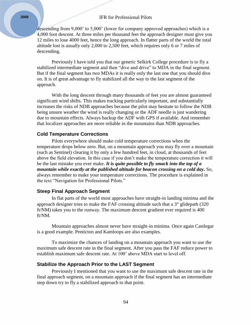
IFR for Professional Pilots
94
2008
descending from 9,000’ to 5,000’ (lower for company approved approaches) which is a
4,000 foot descent. At three miles per thousand feet the approach designer must give you
12 miles to lose 4000 feet, hence the long approach. In flatter parts of the world the total
altitude lost is usually only 2,000 to 2,500 feet, which requires only 6 or 7 miles of
descending.
Previously I have told you that our generic Selkirk College procedure is to fly a
stabilized intermediate segment and then “dive and drive” to MDA in the final segment.
But if the final segment has two MDAs it is really only the last one that you should dive
on. It is of great advantage to fly stabilized all the way to the last segment of the
approach.
With the long descent through many thousands of feet you are almost guaranteed
significant wind shifts. This makes tracking particularly important, and substantially
increases the risks of NDB approaches because the pilot may hesitate to follow the NDB
being unsure weather the wind is really changing or the ADF needle is just wandering
due to mountain effects. Always backup the ADF with GPS if available. And remember
that localizer approaches are more reliable in the mountains than NDB approaches.
Cold Temperature Corrections
Pilots everywhere should make cold temperature corrections when the
temperature drops below zero. But, on a mountain approach you may fly over a mountain
(such as Sentinel) clearing it by only a few hundred feet, in cloud, at thousands of feet
above the field elevation. In this case if you don’t make the temperature correction it will
be the last mistake you ever make. It is quite possible to fly smack into the top of a
mountain while exactly at the published altitude for beacon crossing on a cold day. So,
always remember to make your temperature corrections. The procedure is explained in
the text “Navigation for Professional Pilots.”
Steep Final Approach Segment
In flat parts of the world most approaches have straight-in landing minima and the
approach designer tries to make the FAF crossing altitude such that a 3 glidepath (320
ft/NM) takes you to the runway. The maximum descent gradient ever required is 400
ft/NM.
Mountain approaches almost never have straight-in minima. Once again Castlegar
is a good example. Penticton and Kamloops are also examples.
To maximize the chances of landing on a mountain approach you want to use the
maximum safe descent rate in the final segment. After you pass the FAF reduce power to
establish maximum safe descent rate. At 100’ above MDA start to level off.
Stabilize the Approach Prior to the LAST Segment
Previously I mentioned that you want to use the maximum safe descent rate in the
final approach segment, on a mountain approach if the final segment has an intermediate
step down try to fly a stabilized approach to that point.
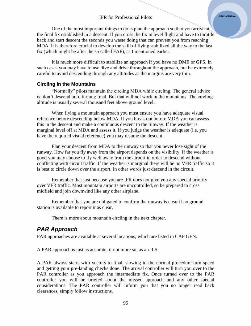
IFR for Professional Pilots
95
Selair.selkirk.ca
One of the most important things to do is plan the approach so that you arrive at
the final fix established in a descent. If you cross the fix in level flight and have to throttle
back and start descent the seconds you waste doing that can prevent you from reaching
MDA. It is therefore crucial to develop the skill of flying stabilized all the way to the last
fix (which might be after the so called FAF), as I mentioned earlier.
It is much more difficult to stabilize an approach if you have no DME or GPS. In
such cases you may have to use dive and drive throughout the approach, but be extremely
careful to avoid descending through any altitudes as the margins are very thin.
Circling in the Mountains
“Normally” pilots maintain the circling MDA while circling. The general advice
is; don’t descend until turning final. But that will not work in the mountains. The circling
altitude is usually several thousand feet above ground level.
When flying a mountain approach you must ensure you have adequate visual
reference before descending below MDA. If you break out before MDA you can assess
this in the descent and make a continuous descent to the runway. If the weather is
marginal level off at MDA and assess it. If you judge the weather is adequate (i.e. you
have the required visual reference) you may resume the descent.
Plan your descent from MDA to the runway so that you never lose sight of the
runway. How far you fly away from the airport depends on the visibility. If the weather is
good you may choose to fly well away from the airport in order to descend without
conflicting with circuit traffic. If the weather is marginal there will be no VFR traffic so it
is best to circle down over the airport. In other words just descend in the circuit.
Remember that just because you are IFR does not give you any special priority
over VFR traffic. Most mountain airports are uncontrolled, so be prepared to cross
midfield and join downwind like any other airplane.
Remember that you are obligated to confirm the runway is clear if no ground
station is available to report it as clear.
There is more about mountain circling in the next chapter.
PAR Approach
PAR approaches are available at several locations, which are listed in CAP GEN.
A PAR approach is just as accurate, if not more so, as an ILS.
A PAR always starts with vectors to final, slowing to the normal procedure turn speed
and getting your pre-landing checks done. The arrival controller will turn you over to the
PAR controller as you approach the intermediate fix. Once turned over to the PAR
controller you will be briefed about the missed approach and any other special
considerations. The PAR controller will inform you that you no longer read back
clearances, simply follow instructions.

IFR for Professional Pilots
96
2008
The PAR controller gives you a running commentary of distance to landing, how many
feet you are off the centerline, how high you are, whether you are above or below the
glidepath, etc. Think of this as “aural CDI needles.” Your job is to hold your heading and
vertical speed constant, changing them only when the controller tells you to. The
approach starts with the controller telling you that you are intercepting the glidepath. At
that point start a descent at five times your groundspeed, and be sure to hold your heading
steady. The controller will tell you if you are getting high or low, listen carefully and
translate the information into revised vertical speed values. If the VSI gets away from you
quickly return to the correct value, don’t wait for the controller to tell you.
The PAR controller will coordinate with the tower. You won’t be able to talk to tower
because you will remain on PAR frequency right through to landing. At some point the
controller will tell you that you are cleared to land.
The PAR controller will tell you when you are approaching “civilian minimums,” which
means 200agl. S/he will then continue to talk you right down to the runway. It is up to
you to confirm you have the required visual reference as you descend through minimums;
if not, start a missed approach. The controller will see that and turn you back over to
departure control for further clearance. From that point on things are exactly like a missed
approach for any other type of approach.
Terrain Separation on Approach At some point the airplane must leave the airway for landing. In order to facilitate this
NavCanada publishes approach procedures for many airports in Canada.
We have already said that approaches are divided into three segments for the purpose of
traffic separation. The same segments are also applicable for terrain separation, i.e. each
segment has a terrain clearance standard.
In many cases there is no airway leading to the IAF, which is the point at which the initial
approach segment begins. To facilitate transition from airway to approach 100-mile safe
altitude and Minimum Sector Altitudes (MSA) are published.
We will examine the terrain separation standards for:
1. 100-mile safe
2. MSA
3. Initial Approach Segment
4. Intermediate Approach Segment
5. Final Approach Segment
6. Circling Airspace
7. Missed Approach Segment
When terminal radar service is available items 1 to 3 on the above list are replaced by
radar vectors, during which the controller takes responsibility for assigning a safe

IFR for Professional Pilots
97
Selair.selkirk.ca
altitude. Radar vectoring altitudes are established by NavCanada. They are similar to
airway MOCA standards except that some vectoring altitudes in Mountainous areas have
been set at 1,000 feet rather that the usual 1,500’ and 2,000’ (most are set at the higher
standard however).
The above 7 areas are discussed from a terrain clearance point of view below.
Terrain Clearance: 100-mile Safe Altitude
Every approach plate lists a 100-NM safe altitude. This provides terrain clearance for 100
NM centered on the same point as the MSA.
100-mile safe altitudes provide 1500 feet of terrain clearance in mountainous areas 2, 3, 4
and 2,000 feet in areas 1 and 5. Elsewhere 1,000 feet of terrain clearance is provided.
100-mile safe altitudes are seldom needed in practice, but they are an important safety
backup. If suddenly all navigation information is lost, climbing to the 100-mile safe
altitude gives you time to sort out the problem. Many pilots refer to this altitude as the
“emergency safe altitude.”
Terrain Clearance: MSA
Minimum Sector Altitudes (MSA) are the primary reference for transitioning from an
airway to an approach when radar service is not available.
MSA provides 1,000 feet of terrain clearance. It is IMPORTANT to note that no extra
clearance is provided in mountainous terrain, so be careful in cold temperatures. A cold
temperature correction should be applied to the MSA when the airport temperature is
below zero.
TIP: It is seldom necessary, or advisable, to descend all the way to MSA altitude. Later in
this book we will talk about flying approaches in detail.
MSA covers a 25 nautical mile area centered on a designated point.
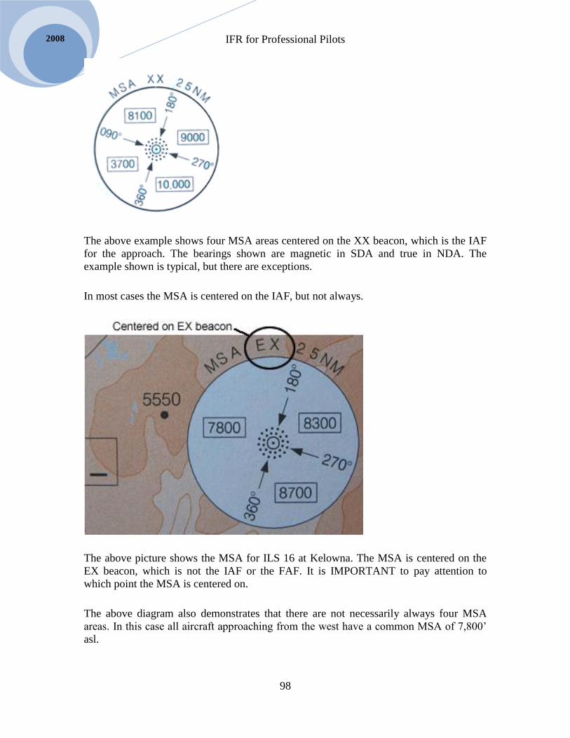
IFR for Professional Pilots
98
2008
The above example shows four MSA areas centered on the XX beacon, which is the IAF
for the approach. The bearings shown are magnetic in SDA and true in NDA. The
example shown is typical, but there are exceptions.
In most cases the MSA is centered on the IAF, but not always.
The above picture shows the MSA for ILS 16 at Kelowna. The MSA is centered on the
EX beacon, which is not the IAF or the FAF. It is IMPORTANT to pay attention to
which point the MSA is centered on.
The above diagram also demonstrates that there are not necessarily always four MSA
areas. In this case all aircraft approaching from the west have a common MSA of 7,800’
asl.

IFR for Professional Pilots
99
Selair.selkirk.ca
In order to use the MSA you must KNOW you are within 25NM of the designated point.
Use DME or GPS if possible to confirm this. Sometimes a cross radial or NDB cross-
bearing can be used. If you make a mistake and descend before you are within 25NM it
could be a fatal mistake, so don’t go by ETA or other potentially inaccurate methods.
Terrain Clearance: Intermediate Segment
As you enter the intermediate segment your terrain clearance decreases to 500 feet. In
other words the FAF crossing altitude is 500 above the highest obstacle in the
Intermediate airspace (see diagram above.)
On the IFR flight test the altitude tolerance changes from +/- 100 to plus only.
Terrain Clearance: Final Segment
As soon as you pass the FAF and enter the final segment the terrain clearance reduces to
250 agl. This is really not a lot when you consider that your altimeter could have a 50
foot error and who knows what error there might be in the altimeter setting, etc.
Therefore, never descend below MDA. It might look to you as though you have more
than 250’ of terrain clearance but that is because the highest obstacle in the final approach
airspace is not usually the runway.
Terrain Clearance: Missed Approach
At the beginning of the missed approach you have only 250 feet of terrain clearance. By
the time you reach the end of the missed approach procedure you will have 1000’ of
terrain clearance provided that you start climbing right at the MAP and climb at least 200
ft/NM.

IFR for Professional Pilots
100
2008

IFR for Professional Pilots
101
Selair.selkirk.ca
Chapter 10
Transition to Landing – Circling
Required Visual Reference
Read RAC 9.19.3
There is a list of things which constitute the required visual reference. If you see at least
one of these things you may continue the approach and land.
a. the runway or runway markings;
b. the runway threshold or threshold markings;
c. the touchdown zone or touchdown zone markings;
d. the approach lights;
e. the approach slope indicator system;
f. the runway identification lights;
g. the threshold and runway end lights;
h. the touchdown zone light;
i. the parallel runway edge lights; or
j. the runway centre line lights
If you do not see any of the above by the time your reach the MAP or DH you initiate the
missed approach procedure.
Landing from an ILS
As you approach the DH on an ILS you will begin to look for the required visual
reference. If there are two pilots the PNF will look for the reference while the PF flies the
approach to the DH. At the DH if the PNF calls “DH, nothing seen” the PF should simply
fly the missed approach procedure and NOT risk looking out the window and becoming
disoriented.
Note that the above procedure is IMPORTANT and therefore if you are the captain and
are not willing to trust your co-pilot to determine that the required visual reference has
been obtained you should consider doing a “pilot monitored approach.” This means that
the co-pilot flies the approach to the DH and will then perform the missed approach
unless the captain calls “runway insight, I have control” prior to, or at, the DH.
When the required visual reference is obtained it is vital to continue to follow the
glidepath to the runway. Therefore the PF is still primarily following instruments while
descending to the runway and taking only glances out the window. The transition to

IFR for Professional Pilots
102
2008
visual flight is quite gradual. If you stop following the instruments you will likely drift
off the centerline and probably below the glidepath.
Landing from a Non-precision approach – straight in
When straight-in minima are published you can descend for a straight-in landing once
you have the required visual reference.
Circling
There are special considerations for circling on mountain approaches and these are
discussed below. First I would like to talk about the “normal” circling situation in which
the circling altitude is just a few hundred feet above ground level.
Circling in minimum visibility, typically 1½ to 2 sm, is quite frankly the most difficult
task in IFR flight.
Review the approach plate ahead of time. Many airports have restrictions such as “no
circling west” etc. Have a plan for how you are going to make your “circuit.”
If there are two pilots on board – and there usually are – make sure you both work
together as a team when circling. The “classic” advice was to circle with the airport on
the PF side, but if there are two pilots it also works to circle so that the PNF can see the
airport. That way the pilot flying can concentrate on flying, maintaining heading and
altitude and let the pilot monitoring call when to turn base and final. As long as the crew
works competently together this can be the least stressful way to circle. As the pilot
flying be sure to brief the PNF of what you expect him to do. If you are captain and your
first officer is flying the circling while you tell him when to turn downwind, base, and
final (airport is on left of aircraft) make sure he knows that you expect him to fly
instruments and that you will maintain visual contact with the runway.
If you have to circle single-pilot you will find that you should still fly instruments about
50%. Use your heading indicator; don’t try to fly purely by visual reference. Plan the
heading for downwind, base, and final. Set the course bar on the HSI parallel to the
runway you are landing on to help visualization. As you turn final you normally want to
start the descent about the time the runway comes into view in the front window, but if
there is rain on the window or it is night try to pickup the PAPI before descending.
Obviously the great concern here is descending too early and landing short. On the other
hand if you wait too long you will land long. It takes a lot of experience to get good at
this. Try to take note of where you start down on days when the weather is good so that
you have a reference the first time you do it in poor visibility.
If you lose visual reference partway through the circling you must initiate a missed
approach, but you are past the missed approach point so what exactly do you do?
The generic advice is to turn toward the center of the airport and begin to climb; then
follow the published missed approach procedure.

IFR for Professional Pilots
103
Selair.selkirk.ca
Keep your wits about you. The above advice is based on the observation that the MAP is
usually at the threshold of the runway and thus turning toward the airport will put you
into the missed approach airspace. But there are lots of approaches where the missed
approach starts somewhere else. If this is the situation consider turning toward the known
MAP, if you can figure out where that is.
Single engine circling
In principle the procedure to circle is the same regardless of how many engines are
operating. In the King Air it will make no difference at all. But, in the B95 you will not
be able to circle with gear-down and flaps extended on one engine. So expect to find that
you need to retract the gear. That means that you have to remember to put it back down
as you turn final.
How to Circle
How to circle is explained in RAC 9.24. Be sure to read and understand it.
There are a few additional tips for effective circling:
Setup the GPS to the runway (in OBS mode) and the moving map scale to 1 or 2.
This makes distance estimation much easier.
When single-pilot it is best to make a left-hand circuit so you can keep the runway
in sight.
When two-pilot you can circle left or right. If you find it convenient to circle with
the PNF on the inside s/he can keep the runway in sight while the PF scans
instruments and observes the GPS. PNF can “call the base turn.”
If you must circle with the PF on the inside the PNF will not be able to see the
runway, but must observe altitude, airspeed and GPS map and call any deviations.
When is a normal landing assured?
The above is a crucial question. RAC 9.24 says that you should remain at the circling
MDA until a normal landing is assured.
Since circling MDA is only 300’ agl 99% of the time you should remain at circling MDA
until either base or final.
Circling in the Mountains
Mountain circling was described earlier under approaches, but here are a few more
thoughts on the subject.
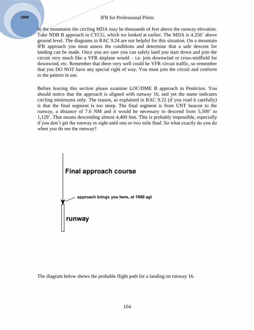
IFR for Professional Pilots
104
2008
In the mountains the circling MDA may be thousands of feet above the runway elevation.
Take NDB B approach in CYCG, which we looked at earlier. The MDA is 4,356’ above
ground level. The diagrams in RAC 9.24 are not helpful for this situation. On a mountain
IFR approach you must assess the conditions and determine that a safe descent for
landing can be made. Once you are sure you can safely land you start down and join the
circuit very much like a VFR airplane would – i.e. join downwind or cross-midfield for
downwind, etc. Remember that there very well could be VFR circuit traffic, so remember
that you DO NOT have any special right of way. You must join the circuit and conform
to the pattern in use.
Before leaving this section please examine LOC/DME B approach in Penticton. You
should notice that the approach is aligned with runway 16, and yet the name indicates
circling minimums only. The reason, as explained in RAC 9.22 (if you read it carefully)
is that the final segment is too steep. The final segment is from UNT beacon to the
runway, a distance of 7.6 NM and it would be necessary to descend from 5,500’ to
1,129’. That means descending almost 4,400 feet. This is probably impossible, especially
if you don’t get the runway in sight until one or two mile final. So what exactly do you do
when you do see the runway?
The diagram below shows the probable flight path for a landing on runway 16.
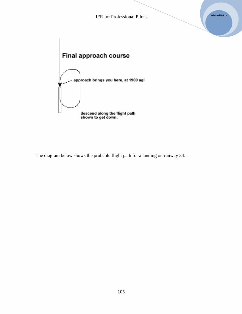
IFR for Professional Pilots
105
Selair.selkirk.ca
The diagram below shows the probable flight path for a landing on runway 34.

IFR for Professional Pilots
106
2008

IFR for Professional Pilots
107
Selair.selkirk.ca
Chapter 11 IFR communications Read COM 5.0
IFR flight is a team effort. When there are two pilots communication between them is
critical. Even one pilot must communicate accurately with ATC. In the long run nothing
is more important to your safety than your ability to communicate.
Communications includes talking with other crew members and passengers as well as on
the radio with ATC and FSS. In this section we will concentrate on radio
communications, but you should make a commitment to apply these principles to your
cockpit communications as well.
Required IFR Radio Calls The following radio calls are required for all applicable IFR flights into and out of
controlled and uncontrolled aerodromes. More information regarding the content of each
radio call follows in the subsequent sections of this chapter. For further details read the
AIM section RAC and the CARS section 602.
DEPARTURE
Departing Controlled Aerodromes:
receive ATIS if available
request and receive IFR clearance from “Clearance Delivery” or “Ground”
receive taxi authorization/instructions from “Ground”
receive takeoff clearance from “Tower”
report at published/requested altitude/position after takeoff to “Departure” or
“Centre”
report when level at altitude initially cleared to
Departing Uncontrolled Aerodromes:
receive AWOS/LWIS if available
receive IFR clearance through AAS, RCO, DRCO, telephone etc.
receive aerodrome advisory and/or report taxiing as applicable
report entering active runway with departure intentions
report departing circuit/clear of zone and when requested or a.s.a.p. after
departing the zone to “Centre”
report when level at altitude initially cleared to
ENROUTE
IFR for Professional Pilots
108
2008
report over compulsory reporting points unless radar identified and
whenever/wherever requested by controlling agency
switch to and report on new frequency whenever instructed to by controlling
agency
report PIREPS whenever requested to or when conditions differ significantly than
forecast (MET 1.1.6, MET 2.1)
report CIRVIS, meteorites, forest fires, pollution as applicable (RAC 1.12)
report failure of equipment, emergencies
request weather updates with FISE on 126.7 as applicable
after being assigned a climb/descent, report leaving cruise altitude as well as when
level at the assigned altitude
after being cleared to commence an approach, report leaving cruise altitude
if in uncontrolled IFR enroute: broadcast intentions on 126.7 prior to changing
altitude or commencing approach
ARRIVAL
Arriving at Controlled Aerodromes:
receive ATIS if available
if in uncontrolled IFR enroute: report to “Tower” 25 nm from airport with ETA
to receive approach clearance
switch to and report on new frequency (“Arrival”, “Tower” etc.) when instructed
to by controlling agency
report over mandatory reporting points on arrival/approach and when/where
requested by controlling agency
unless on radar vectors, report your ETA to the approach facility to “Tower”
receive clearance for STAR, approach, and landing
remain on “Tower” until assigned (industry practice) to switch frequency to
“Ground” to request taxi clearance
Arriving at Uncontrolled Aerodromes:
receive AWOS/LWIS if available
establish initial communications with ground station and state the ETL at least 5
min. prior to commencing approach (if you have only one radio you must get
permission to temporarily switch frequencies--see RAC 9.11)
switch to and report on new frequency when instructed to by controlling agency
report over mandatory reporting points on arrival/approach and when/where
requested by controlling agency
report:
o when passing the fix outbound or when intercepting final approach course
as applicable,

IFR for Professional Pilots
109
Selair.selkirk.ca
o when passing the fix inbound or 3 min. before ETL as applicable,
o on final,
o when commencing a circling maneuver, and
o as soon as practicable after initiating a missed approach
o on final leg
report when exiting active runway
Enunciate
When – you – speak – say – each – word – individually.
Repeat out loud:
I – will – concentrate – on – saying – words – and – not – slur – them – together.
The ident of your airplane is NOT: gofserrapoopalfa
Say it:
Golf – Sierra – Poppa – Alpha
I have noticed that most people feel a compulsion to speak quickly. This WILL waste
time in IFR flight. Controllers are going to be asking you to, “Say again” frequently,
which will take more time than if you had simply spoken clearly to begin with.
The local FSS at home base knows the ident of your airplane and can understand
gofserrapoopalfa. That’s too bad, because it breeds complacency about enunciation.
Please try to – speak – each – word – individually – when – you – talk – on – the – radio.
It is really hard to do a good job of speaking on the radio if you insist on speaking badly
the rest of the time. I strongly recommend that you make a commitment to speak well all
the time. I recommend going so far as to use standard aviation phrasing in everyday life.
For years I have gotten into the habit that when someone mumbles I don’t say, “What?”
instead I use, “Say again”; I do this even at the grocery store and no one has ever
complained. Similarly I use negative and affirmative rather than no and yes, etc.
Know the key phrases that have been approved for aviation use. Use them appropriately.
This may be the single easiest way to convince others (fellow pilots and ATC) that you
are professional. It is amazing how many pilots don’t know the difference between
“repeat” and “say again” or what “confirm” means. The phrases are listed below with
explanations. I strongly recommend using them as described in day to day conversation
to get used to them. Always use them properly on the radio. To do otherwise reveals you
as a poser pilot.
IFR for Professional Pilots
110
2008
Say less to say more
You have probably heard the saying “less is more” which has environmental and other
philosophical overtones. When it comes to speaking I have a similar principle based on
the observation that the human mind can only absorb a limited amount of information
into short term memory. Try reading this list to a friend:
Apple, banana, peach, orange, mango, apricot, pear.
Have your friend repeat the list. They probably can’t do it accurately.
Should you get on the radio and tell FSS everything from where you are to where you
were to where you are going to how bumpy it is and that you saw one airplane but not the
other and; is there anyone in the practice area? and have a nice day….?
Know what needs to be said. Say that, and ONLY that.
Know When and What to Report
When a controller assigns you a new heading do you report getting to that heading? No,
but when s/he assigns you a new altitude you do report reaching that. When you are
cleared for an approach do you report reaching the procedure turn altitude? No. There are
“rules” governing all this that you must know and follow. We will go over them.
Position Reports
When ATC radar identifies you it is no longer necessary to report at reporting points. If
you are not radar identified you must make a full position report, following the format
on the back cover of the CFS.
In a radar environment ATC will often make a request such as:
ATC: ABC, report Active Pass
Pilot: report Active Pass, ABC
ATC: Roger
Pilot: Victoria terminal, ABC at Active Pass [several minutes later]
ATC: ABC roger. Switch Victoria terminal on 133.95
The report does NOT follow a full position report format. The controller just wants to be
reminded, so s/he can give you further clearance, perhaps an altitude change or hand-off.
The rule is that if you are radar identified full position report is not needed; use the format
above.

IFR for Professional Pilots
111
Selair.selkirk.ca
Report Altitudes
When you are cleared to a new altitude you must report leaving the last assigned
altitude and reaching the new assigned altitude. See verbatim read backs below for
further examples.
When you are cleared for an approach you are NOT assigned a new altitude (normally)
therefore only report leaving the last assigned altitude. Here is a typical exchange.
ATC: ABC cleared to the Somespot airport for the NDB runway two six approach.
Pilot: cleared to the Somespot airport for the NDB runway two six approach, leaving
niner thousand at this time, ABC
ATC: Roger
Notice that the pilot decided to descend right away and so included that in the read back.
It would be just as acceptable:
ATC: ABC cleared to the Somespot airport for the NDB runway two six approach.
Pilot: cleared to the Somespot airport for the NDB runway two six approach, ABC
ATC: Roger
Pilot: Edmonton Center, ABC leaving niner thousand [at a later time when the pilot is
ready]
ATC: Roger
The pilot will NOT report subsequent altitudes (MSA, Procedure turn, FAF, MDA, etc.)
to ATC.
Report on New Frequency
When handed off to a new controller use the following format.
ATC: ABC switch Victoria terminal one three two decimal seven
Pilot: switching, ABC
Pilot: Victoria terminal, Lear FABC level six thousand [on the new frequency]
ATC: ABC, squawk ident
Notice the format of the standard report on new frequency is.
Agency – Type – Ident - Altitude
There are a few situations in which you want to say MORE than above, they are covered
next:
Contact with Departure
Pilot: Calgary departure, Lear FABC off three four, through four thousand two hundred
for seven thousand.

IFR for Professional Pilots
112
2008
ATC: ABC radar identified
The format for initial contact with departure is:
Agency – Type – Ident – Runway- Altitude
When an airplane is climbing or descending at the time of hand off the new controller
must always be told the present altitude to the nearest hundred feet, and the altitude
cleared to.
Contact with Arrival
ATC: ABC switch Calgary arrival one two five decimal niner
Pilot: Switching, ABC
Pilot: Calgary arrival, Lear FABC, level one one thousand, with November
ATC: ABC, squawk ident
The format is:
Agency – Type – Ident – Altitude - ATIS
If the pilot has fallen behind with his duties the exchange below would be typical:
ATC: ABC switch Calgary arrival one two five decimal niner
Pilot: Switching, ABC
Pilot: Calgary arrival, Lear FABC, level one one thousand, negative ATIS
ATC: ABC, squawk ident, ATIS information November
Pilot: Squawk ident, ABC
ATC: ABC, radar identified
Pilot: Calgary arrival, ABC has November [later, when the pilot has ATIS]
ATC: ABC, roger
If you don’t have the ATIS tell the controller so, as above. When you get it tell him/her
that too.
Notice in the above exchange that when the controller said, “ABC, squawk ident, ATIS
information November” the pilot correctly recognizes that only squawk ident is an
instruction, so only that is read back.
Read Back – Verbatim
In IFR most clearances and instructions should be read back verbatim. In this section we
will encounter one or two exceptions, but normally verbatim is the key.
Verbatim means word for word. Here is the WRONG way to do it.

IFR for Professional Pilots
113
Selair.selkirk.ca
ATC: ABC Maintain four thousand, climbing through three thousand direct Hamstrong
VOR
Pilot: direct Hamstrong VOR at three thousand, maintain four thousand, ABC
ATC: Roger
The read back is correct(ish), but why does the pilot feel the need to reorder the words?
Doing this makes it much more likely that a mistake will be made. For example “at
3,000” implies leveling off. Could a mistake be made? Maybe. The ideal exchange is:
ATC: ABC Maintain four thousand, climbing through three thousand direct Hamstrong
VOR
Pilot: Maintain four thousand, through three thousand direct Hamstrong VOR, ABC
ATC: Roger
Note that it is acceptable to drop words that add no information. In the example the pilot
dropped the word “climbing.” If in doubt leave all the words in. What matters most is to
see the clearance as having elements and read back each element, in the order given.
Below is an exchange that follows the verbatim rule, but is too stilted as a result.
ATC: ABC maintain four thousand
Pilot ABC maintain four thousand. Leaving six thousand for four thousand.
ATC: Roger
Strictly speaking the above is a perfect exchange. Most pilots will shorten it as follows,
which is recommended.
ATC: ABC maintain four thousand
Pilot Leaving six thousand for four thousand, ABC
ATC: Roger
Pilot: Vancouver Terminal, ABC level four thousand [when within 100 of new altitude]
ATC: ABC, roger
This bends the verbatim rules, but is an approved deviation.
Don’t read back things that aren’t clearances or instructions. For example:
ATC: ABC, traffic two o’clock four miles northbound, altitude unknown
Pilot: looking, ABC
Phonetic Alphabet
You must know your phonetic alphabet. You probably already do so I won’t take up
space with it here.

IFR for Professional Pilots
114
2008
You must know when to use phonetics and when not to. If you are spelling something for
the other pilot in the cockpit most pilots don’t use phonetics unless the first attempt fails.
Pilot 1: Nice to meet you, my name is garf
Pilot 2: Did you say garf? How do you spell that?
Pilot 1: G-A-R-T-H.
Pilot 2: Sorry Garth. My name is Ray
You do NOT use phonetics when a letter is used to represent an aircraft type. For
example C-172 (spoken cee one seventy two) not Charlie one seven two. Or L1011
(spoken El ten eleven) not echo one zero one one.
Except for special cases as indicated above, phonetics should be used on the radio. Your
aircraft ident is always in phonetics.
When flying in Canada drop the Charlie. I.E. Golf Sierra Poppa Alpha, not Charlie Golf
Sierra Poppa Alpha.
ALWAYS start with four letters in your ident. LISTEN to the controller, if s/he shortens
your ident to three or two letters you should follow suit.
Pilot: Vancouver tower, foxtrot alpha bravo Charlie, ready for takeoff runway two six
left.
Tower: foxtrot alpha bravo Charlie, cleared takeoff two six left.
Pilot: foxtrot alpha bravo Charlie
Notice in the above exchange the tower did NOT follow common practice of shortening
the ident to ABC. Therefore the pilot is committed to use FABC until such time that the
controller makes the switch. The reason is that it is possible that GABC is also in the
area, and ATC would know that.
By the Numbers
Numbers are used extensively in aviation. Headings, altitudes, transponder codes, wind
speed, etc. are all numbers.
A number is NOT treated as a number when it is an aircraft type. A C-172 is a one
seventy two. That isn’t a number any more than Skyhawk is. Similarly an El ten eleven is
not a number, nor is a Dee Cee ten or Em Dee ninety or a Beech ninety five.
When numbers are numbers they are spoken one-digit-at-a-time. See below for more
details.

IFR for Professional Pilots
115
Selair.selkirk.ca
Headings
Headings are always specified with three digits. If necessary a leading zero is added. 270
is spoken, “Two seven zero.” 030 is zero three zero.
Altitudes
Altitudes are spoken in thousands and hundreds. 13,500 is spoken, “One three thousand
five hundred.”
Try this list of altitudes:
500
4,000
9,000
9,500
10,000
14,000
17,800
Five hundred
Four thousand
Niner thousand
Niner thousand five hundred
One zero thousand
One four thousand
One seven thousand eight hundred
Altimeter Setting
Altimeter settings in Canada are given in inches of mercury. Four digits are given; there
is NO NEED to say the word decimal.
29.92 is: two niner niner two
30.14 is: three zero one four
By rule ATC controllers are required to repeat the altimeter setting when it is less than
28.92.
28.76 is: two eight seven six. I say again, two eight seven six
The above is the format the controller will use. You do not need to, but if you don’t hear
it for an altimeter setting less than 28.92 you MUST question it because either the
controller is being lazy, or you heard it wrong.
IFR for Professional Pilots
116
2008
ATC: altimeter two eight seven five
Pilot: Confirm two eight seven five [emphasize eight to draw controller’s attention]
See the note below for the use of the key word confirm, which the pilot has used properly
above.
Key Phrases I have used several key phrases above. You must get to know all these and use them
appropriately.
In everything that follows I will assume that you know the rules about phonetics and
numbers so I will just write the letters and numbers and you are expected to translate
them according to the rules.
Say again – repeat
ATC: ABC turn left heading 265
Pilot: say again new heading, ABC
ATC: ABC, turn left heading 265
Pilot: left 265, ABC
ATC: ABC you are number four to land
Pilot: ABC, my left engine is on fire. Repeat, left engine on fire [add emphasis]
ATC: ABC roger. Cleared to land
You want someone to “say again” if you didn’t hear them the first time.
You are repeating yourself, for emphasis when you use the word repeat.
Say Your….
It happens all the time; some other airplane reports and you miss their ident. All you have
to do is say, “station calling, say your ident.”
If you want to know another aircraft’s altitude you would say, “GDEF, say your altitude”
Of course ATC will use it on you as well:
ATC: ABC, say your heading
Pilot: 040, ABC
ATC: ABC, turn right heading 055
Pilot: right 055, ABC
ATC: roger
IFR for Professional Pilots
117
Selair.selkirk.ca
Roger, Confirm, Affirmative, Negative
ATC: ABC, confirm steering 065?
Pilot: roger. 065, ABC
Confirm is a question. It cannot be an answer. The above utilization is correct. If the
pilot answers “confirmed” that is a dead give away that he is a poser. It would be
perfectly acceptable for the pilot to answer, “Affirmative” or “Affirmative, 065”
Roger is an acknowledgement. In the above case the pilot is acknowledging the
question and answering 065, or acknowledging the heading is 065; the perspective
doesn’t matter, but it would have been better to just say affirmative.
Often you can use either Roger or affirmative, but affirmative carries more information
and is therefore preferable when applicable.
Consider the following exchange:
ATC: ABC, confirm steering 065?
Pilot: Negative. Heading 200, ABC
ATC: ABC Roger. Turn left heading 065, vectors to ILS 12
This exchange is also correct. The controller asks a question by using confirm. The pilot
answers, “Negative.” If the pilot only said negative the controller might be forced to ask
what the actual heading is, so this pilot wisely included the information.
ATC: ABC, confirm steering 065?
Pilot: Negative. Heading 200, ABC
ATC: you were told to steer 065. Turn now!
Pilot: Roger, left 065, ABC
Don’t get flustered. Every professional pilot has been through the above. If you can keep
your head while all others about you are losing theirs ….. Don’t let the chewing out bug
you. If you can continue to formulate proper RT calls after being chewed out, as this pilot
did, ATC will soon forgive you and recognize you for the professional you are. Airline
pilots miss calls at times. The controller’s response is not only rude but incorrect – the
ident of the aircraft called is missing
Pilot: Confirm ABC is cleared to land [from pilot on short final]
ATC: ABC, roger
This pilot used the word confirm correctly. This situation happens a lot – you just can’t
remember if the controller cleared you to land or not. This is a perfect time to use the
word confirm, because you are asking a question. For some reason pilots have a lot of
trouble summoning up this call. Note that the controller would have been better advised
to say affirmative.

IFR for Professional Pilots
118
2008
Summary: The most common confusion regarding these terms is to use confirm, or
confirmed when you really mean affirmative. Please work on it.
When able – Until able
ATC: ABC, go direct White Rock when able.
Pilot: Direct White Rock when able, ABC
In the above exchange the controller is telling the pilot that as soon as s/he can get the
WC beacon tuned and identified s/he should go direct to it. The pilot has done the
standard thing, which is read back the clearance verbatim. Is that the best thing to do?
If the pilot is not presently able to go direct White Rock then the above exchange is
perfect. When the pilot gets WC tuned and identified and begins to track toward it s/he
should call ATC and say:
Pilot: ABC now proceeding direct White Rock
ATC: Roger
If the pilot is ready to go to White Rock when cleared the exchange should be:
ATC: ABC, go direct White Rock when able.
Pilot: Direct White Rock at this time, ABC
ATC: Roger
The above bends the verbatim rule, but makes sense.
Controllers sometimes clear you to do one thing until you are able to do another thing. An
example exchange would be:
ATC: ABC, heading 030 until able direct White Rock
Pilot: 030 until able direct White Rock, ABC
ATC: roger
Pilot: Victoria terminal, ABC now proceeding direct White Rock
ATC: ABC, roger
Check
Pilot: Aircraft on short final, check your gear down
The word check in the above example is used as an urgent instruction. This pilot is really
saying, “Look at the green lights on your panel and make sure they are green!!” The
unspoken presumption is, “I think you forgot to put your gear down.” In this form the
IFR for Professional Pilots
119
Selair.selkirk.ca
word check is a substitute for confirm, but carries a sense of urgency. By using it
sparingly it carries more weight.
Another situation in which this key-word arises is:
ATC: ABC turn left heading 270, vectors to ILS 09, expect a short gate
Pilot: Left heading 270, vectors to ILS 09, check remarks
In this case by saying, “check remarks” the pilot means that s/he took note of the previous
remark. In this case check is a substitute for roger. The pilot could have said “roger
remarks,” but this seems like bad movie dialogue, so pilots prefer “check remarks.”
Sample Radio Calls – Lear JET: CYVR to CYYC I will present sample IFR radio calls for a flight in an RNAV equipped Lear Jet flying
Vancouver to Calgary. After each exchange I provide commentary about why the calls
are structured as shown and any optional alternatives.
Consider these calls as templates into which the details of your own calls can be fit.
Memorize the structure of each call as explained in the notes.
You should assume the weather is IMC, with approximately half mile visibility at both
airports.
The airplane has filed the preferred high altitude RNAV route, which is ADSIX KESTA
KETTL. You may assume the aircraft has the equipment for an RNAV star at Calgary
and that is included in the scenario.
Clearance Delivery
Pilot: Vancouver clearance delivery, Lear FABC IFR to Calgary at FL 330
ATC: FABC, departure on 26 right, cleared to Calgary airport via Vancouver 4
departure, flight plan route, squawk 3511.
Pilot: Squawk 3511, FABC
Per RAC 6.1 only the transponder code need be read back in this case. At a busy airport
like CYVR it would be unprofessional to do more. Note that the controller did not
shorten the ident (FABC), hence the pilot refers to himself as FABC not ABC.
All SIDs specify an altitude to maintain, but they normally have
communications failure procedures that refer to the flight planned
altitude. That is why it is normal to state the flight plan altitude
when requesting clearance. In the unlikely event of a
communications failure we don’t want any confusion between you
and ATC about what altitude you are going to maintain.

IFR for Professional Pilots
120
2008
Pilot: Vancouver clearance delivery, King Air GSEL IFR to
Castlegar at FL 230
ATC: SEL, departure on 08 right, Richmond one SID, flight plan
route, maintain 3,000, squawk 5124
Pilot: Maintain 3,000, squawk 5124, SEL
In this case the controller has amended the altitude in the SID to
3,000. By rule, this must be read back. In this example the
controller shortened the ident to SEL so the pilot followed the
controllers lead
Ground
Pilot: Vancouver ground, Lear FABC
ATC: ABC ground, go ahead
Pilot: ABC at the Aerocenter, IFR Calgary, with Whiskey
ATC: ABC, altimeter 29.64, taxi via alpha, hotel. Hold short 26 left.
Pilot: 29.64. Hold short 26 left, ABC
The pilot makes an initial contact in the format station – type – ident ATC then asks the
pilot to go ahead.
The pilot describes his/her position; alternatively s/he could have said, “On apron two.”
And tells the controller s/he is IFR to Calgary and has the ATIS. The controller already
has a strip for the airplane and will annotate it as the airplane taxis. The controller must
get the airplane from the south side of the airport to the north east corner without conflict
with landing traffic on 26L.
The controller clears the airplane only part way to 26R, and specifies to hold short of
26L. All hold short clearances must be read back. (The controller will annotate hold
short 26L on the strip).
Pilot: Vancouver ground, ABC holding short 26 left on hotel.
ATC: ABC cleared across 26 left. Hold short delta.
Pilot: hold short of delta, ABC
ATC: roger
The pilot reports once at the hold short point. It is NOT necessary to request further.
Many pilots do, but it is redundant.
The ground controller checks with the south tower controller and when the runway is not
in use clears the airplane across (there might be some time elapsed here due to traffic
using 26L.) The instruction to hold short of delta implies other taxiing traffic.

IFR for Professional Pilots
121
Selair.selkirk.ca
Pilot: Vancouver ground, ABC holding short of delta
ATC: ABC roger, hold short. 767 traffic crossing right to left, report when he is past
ABC roger
Pilot: Vancouver ground, 767 has passed ABC
ATC: ABC roger. Cleared taxi 26 right via route delta
Pilot: 26 right via route delta, ABC
ATC: roger
The pilot reports holding short of taxiway D. The controller asks him/her to report when a
Boeing 767 on taxiway D is past. Remember that in ½ mile visibility the controller is
working blind. There is no ground radar, so the controller is using a form of procedural
separation to keep track of where everyone is.
When ABC reports the 767 past, the controller checks his board for conflicts and finding
none clears the Lear to 26R via route Delta. Vancouver has Coded Taxi Routes – look
them up in your CAP2. The instruction at the top of the page requires the pilot to read
back the code. So the pilot reads back, “26 right via route delta” just as s/he should.
Pilot: Vancouver ground, Lear FABC
ATC: FABC go ahead
Pilot: FABC on Juliet holding short of kilo. Request clearance to 26 right.
ATC: ABC roger, do you see a Jazz Dash 8 entering Juliet from Kilo?
Pilot: affirmative, ABC
ATC: ABC, behind that traffic, cleared 26 right via Juliet, Mike, Mike niner.
Pilot: ABC
At the specified point in route delta the pilot switches to the north ground control
frequency. The example shows a textbook call in the same format previously used:
station – type – ident. While it is true that many pilots would skip this initial call, it is
not recommended. The controller has a tough job keeping track of the traffic in this low
visibility procedural scenario. Give the controller a chance to get ready by making an
initial call. If the weather is better you might want to skip this call – that’s where your
professional judgment will have to come in.
The controller asks the pilot if s/he sees other traffic. The pilot uses the word affirmative,
NOT roger to indicate that s/he does.
The controller issues taxi instructions to the airplane, but there is no need to read all this
back. The clearance contains no hold short instruction that require read back. The pilot
simply acknowledges with his/her ident. Many pilots would read back, “26 right via
Juliet, Mike, Mike niner, ABC” It’s not a problem if you want to do this, but it is not
required in this case.
Tower
Pilot: Vancouver tower, Lear FABC, ready for takeoff runway 26 right.

IFR for Professional Pilots
122
2008
ATC: ABC roger. Number three for departure
Pilot: ABC
When calling tower the request for takeoff should be included in the first call – as this
pilot does.
Many pilots would leave out the tower frequency, but the above demonstration is by the
book and I recommend you follow this format. Most airports don’t have two tower
frequencies however so the most normal form of this call is, “Somespot tower, Lear
FABC ready for takeoff runway 12.”
Notice that ATC advises the pilot that s/he is number three for departure; the implication
is that the pilot called with two other airplanes ahead in the lineup. This is proper
procedure on the pilot’s part. DO NOT wait until you are first in line to call for takeoff
clearance, especially in poor visibility. Calling right away helps the tower controller
organize the strips on his board in the order for takeoff.
ATC: ABC line up on 26 right.
Pilot: line up on 26 right, ABC
ATC: ABC, wind 240 at 15, cleared takeoff runway 26 right
Pilot: ABC
Only the calls related to this flight are being shown, but the pilot would have heard the
two aircraft ahead cleared for takeoff and thus be able to figure out when to perform the
“below the line” items on the pre-takeoff checklist. When ATC clears him/her to position
it would come as no surprise because the aircraft ahead would have been cleared for
takeoff shortly before.
The pilot must read back a clearance to line up.
When the aircraft ahead reaches the necessary IFR separation distance, as we previously
discussed, the tower controller clears the Lear jet for takeoff. The pilot does not need to
read this back, ident only as shown is adequate although many pilots would say, “cleared
for takeoff, ABC” consider this an acceptable redundancy.
Departure
Pilot: Vancouver departure, Lear FABC, off 26 right through 1,100 for 7,000.
ATC: ABC, radar identified
The standard call to departure takes the form: station – type – ident– runway of
departure – altitude. Note that this is the same format used previously with the addition
of runway of departure and altitude. Get to know this format.

IFR for Professional Pilots
123
Selair.selkirk.ca
In most cases there is only one departure frequency thus the most common form of this
call is, “Somespot departure, Lear FABC off runway 12, through 1,000 for 6,000.”
It is important to report the ACTUAL altitude the aircraft is passing through when the
call is made – rounded to the nearest 100 feet. The SID instructs the pilot to call at 1,000’,
but in the above example the pilot was a tad late and called at 1,100’. The call is used by
the controller to check the accuracy of the Mode-C readout, which is why the actual
altitude must be reported.
ATC: ABC, maintain 11,000, through 7,000 turn left heading 160 vectors enroute
Pilot: Maintain 11,000. Through 7,000 left 160, ABC
ATC: roger
As expected, the controller begins vectoring the airplane. The pilot reads back each
clearance verbatim (with redundant words dropped.) Pay particular attention to the fact
that the pilot reads back each clearance with its elements in the same order the controller
issues them.
Note that the clearance to 11,000 was issued before the airplane reached 7,000 – that is
why there is no call leveling 7,000.
ATC: ABC, when able, direct ADSIX
Pilot: direct ADSIX at this time, ABC
ATC: roger
The controller has used the key-phrase “when able” s/he wants the airplane to go direct
ADSIX as soon as they get it tuned up on the RNAV. It turns out the pilot is ready, so
rather than read back verbatim, in this case s/he responds, “Direct ADSIX at this time,
ABC.”
ATC: ABC, maintain 15,000
Pilot: Maintain 15,000, ABC
ATC: ABC roger. Switch Vancouver Center 135.0
Pilot: Switching
Pilot: Vancouver Center, Lear FABC through 12,400 for 15,000
ATC: ABC, squawk ident
Pilot: Squawk ident, ABC
ATC: ABC, radar identified.
The controller clears the airplane up to 15,000 and hands it off to the center controller for
that sector. The pilot acknowledges by saying, “switching” which is all that is needed.
The pilot was anticipating this frequency; it is on the HI chart. If the departure controller
had said a frequency that the pilot did not expect it would be worth reading back, it could
even be turned into a question by adding the key-word confirm; “confirm Vancouver

IFR for Professional Pilots
124
2008
center on 135.5?” followed by the controller saying, “Negative, 135.0” and then from the
pilot, “Roger, 135.0, ABC”
Notice that “squawk ident” is an instruction and as such must be read back. A lot of
pilots just push the ident button, but the instruction should be read back first to make sure
no confusion exists.
Notice the standard format that the pilot uses when contacting a new controller: station –
type – ident – altitude. This will be used a million times in your life, so get to know it.
Pilot: Vancouver center, ABC level 15,000
ATC: ABC roger, expect higher in 10 miles
Pilot: ABC
The pilot must report reaching the assigned altitude. There is a traffic conflict so the
controller informs the pilot that s/he can’t clear him higher for another 10 miles. This is
NOT a clearance, so the pilot simply acknowledges with the ident, ABC.
ATC: ABC, maintain Flight Level 230
Pilot: out of 15,000 for Flight Level 230, ABC
As was previously explained this is a recommended variance from the strict verbatim
read back, which would have been, “Maintain Flight Level 230, leaving 15,000 for Flight
Level 230.” While technically correct very few pilots use this very formal read back.
ATC: ABC, maintain Flight Level 330
Pilot: maintain Flight Level 330, ABC
ATC: roger
The controller now clears the airplane to the final altitude. Notice that the airplane never
leveled at FL230, i.e. the clearance to FL330 came before the airplane reached FL230.
Why didn’t the controller just clear the airplane directly to FL330? Because there was a
traffic conflict – probably someone at FL240 who had to “get out of the way” first.
Pilot: Vancouver center, ABC level Flight Level 330
ATC: roger
From this point on things become very routine. The airplane will be handed from sector
to sector. This is a relatively short flight so there will be only a couple of hand offs:
ATC: ABC switch Vancouver center on 134.55
Pilot: Switching, ABC
Pilot: Vancouver center, Lear FABC level Flight Level 330
ATC: ABC, squawk ident
Pilot: Squawk ident, ABC

IFR for Professional Pilots
125
Selair.selkirk.ca
ATC: ABC is radar identified
Then after some more time elapses
ATC: ABC switch Edmonton center on 133.3
Pilot: Switching, ABC
Pilot: Edmonton center, Lear FABC level Flight Level 330
ATC: ABC, squawk ident
Pilot: Squawk ident, ABC
ATC: ABC is radar identified
This is the last enroute hand off for this flight, but if the airplane was going all the way to
Toronto the next four hours would just be a repeat of the above pattern every 30 to 45
minutes.
Not shown in this scenario are any calls made to FSS to check weather, or any calls on
company frequency to dispatch. This scenario shows only communications with ATC.
ATC: ABC, maintain FL 250 expect Handa Five
Pilot: leaving Flight Level 330 for 250, ABC
The airplane is about 55NM from Opale now and the controller begins to bring it down.
“Expect the Handa Five arrival” is not a clearance and so need not be read back. By this
point the pilot has the ATIS and knows that runway 16 is active.
ATC: ABC, Calgary altimeter 29.75, maintain 16,000, cross Opale Flight Level 210 or
below
Pilot: 29.75, maintain 16,000, cross Opale Flight Level 210 or below, ABC
The controller has cleared the airplane down to 16,000 before it leveled at FL250.
The controller must provide the current altimeter setting before clearing the airplane out
of the standard pressure airspace. The pilot should read it back.
The clearance is to 16,000 with a restriction to cross Opale at FL210 or lower.
Restrictions must be read back.
ATC: ABC, switch Calgary arrival 125.9
Pilot: switching, ABC
Arrival
Pilot: Calgary arrival, Lear FABC descending through Flight level 230 for 16,000 with
ATIS X-ray
ATC: FABC, squawk ident. Calgary altimeter 29.75

IFR for Professional Pilots
126
2008
Pilot: 29.75, squawk ident, FABC
ATC: FABC, radar identified. Cleared the Handa Five arrival, report Opale
Pilot: Cleared the Handa Five arrival, report Opale, FABC
Prior to this exchange the Lear was not cleared for the Handa Five – they were just
expecting it. Now they have the clearance.
Note that the controller used all four letters in FABC, so the pilot followed suit.
The controller has requested a call by Opale:
Pilot: Calgary arrival, FABC is by Opale
ATC: FABC roger, maintain 14,000 at your discretion. Be advised aircraft ident GABC is
on this frequency also
Pilot: 14,000 at my discretion. Check remarks, FABC
ATC: roger
“14,000 at your discretion” means that the aircraft can descend as quickly or slowly as
the pilot likes. This is a “restriction” technically, so should be read back.
The controller has revealed to the pilot that GABC is on the frequency. No read back is
required but it is polite to acknowledge, which this pilot does; the key word “check”
means “I have taken note of…”
The controller will likely not speak with this aircraft again until it is past Adsek
ATC: FABC, maintain 8,000
Pilot: maintain 8,000, FABC
ATC: roger
The aircraft is now cleared down to 8,000’. The chart tells the pilot not to expect anything
lower than 7,500’, so all is as expected and the pilot likely expects no further calls until
s/he is cleared for the approach
ATC: FABC, maintain 7,000 until established on final, cleared the straight-in ILS 16
approach
Pilot: Maintain 7,000 until established on final, cleared straight-in ILS 16 approach,
FABC
On an RNAV arrival the approach clearance can come early or late, here we have an
example of an early clearance; the aircraft is at least 3NM from UBTON. By clearing the
airplane for the approach the STAR is CLOSED. The pilot can follow the RNAV to
ELERO and then intercept the glidepath.
IFR for Professional Pilots
127
Selair.selkirk.ca
The controller clears the airplane to 7,000’, but the pilot will plan his/her descent so as to
cross UBTON at 7,500’ or above. The airplane will not descend below 7,000’ until
intercepting the glidepath on final.
The above scenario only works if the controller has all the airplanes following along in
trail with good spacing between them. If spacing is not good the controller will not clear
the airplane for the approach. According to the STAR the pilot will then fly heading 343
from UBTON and expect vectors to final. This is called an OPEN STAR.
On the closed STAR the controller will simply watch this airplane follow the route
around onto final and once it is established on final s/he will hand it off to tower.
ATC: FABC switch Calgary tower 118.4
Pilot: Switching, FABC
Pilot: Calgary tower, Lear FABC at 11 DME, with X-ray
ATC: FABC roger, altimeter 29.76, wind 140 at 25, report SARCEE.
Pilot: 29.76, report SARCEE, FABC
Pilot: Calgary tower, FABC by SARCEE beacon inbound.
ATC: FABC number one
Pilot: FABC
ATC: ABC cleared to land
Pilot: ABC
Notice that the controller has shortened the ident to ABC (apparently GABC is gone.)
The pilot followed suit.
ATC: ABC, what is your destination on the field?
Pilot: Apron five
ATC: roger, plan to clear left on C3
Pilot: roger
The airplane is still on final during this exchange. Exchanges of this type are quite
common with tower.
Ground
The next call will be to ground after the airplane lands.
Pilot: Calgary ground, FABC is on C3, request taxi to Apron five
ATC: ABC, cleared to apron five via Charlie, X-ray
Pilot: ABC
The controller has cleared the airplane all the way to apron five. This requires crossing
runway 07, but no restriction was issued therefore the pilot is cleared all the way. Many

IFR for Professional Pilots
128
2008
pilots can’t resist calling just before crossing the runway with something like, “Ground,
confirm ABC is cleared across 07?” There is a lot to be said for this, but you have to use
your discretion. If the controller is busy and you can hear that 07 is not in use don’t waste
air time with this call (it is not legally required.)
Sample Radio Calls – King Air: CYXX to CYYJ The sample radio calls in this scenario are for a low altitude flight from Abbotsford to
Victoria. Both airports are controlled. Abbotsford has no clearance delivery.
The calls in this scenario are very similar to the ones new IFR pilots will encounter in a
training environment. For the purpose of this flight the King Air is IFR but the weather is
VMC.
Ground
Pilot: Abbotsford ground, King Air GSEL
ATC: GSEL go ahead
Pilot: GSEL is at the base of the tower, IFR to Victoria at 6000, with India.
ATC: SEL is cleared to the Victoria airport via the Abbotsford Seven departure direct
Whatcom VOR, Victor 495. Squawk 3521.
Pilot: Squawk 3521, SEL
ATC: roger. Are you ready to taxi at this time?
Pilot: affirmative
ATC: roger. Altimeter 30.21, wind 220 at 10. Taxi runway 19, hold short on alpha.
Pilot: 30.21, hold short 19 on alpha.
The standard form of the call to ground is: station – type – ident
The pilot has the option of whether to read back the IFR clearance; s/he chooses to only
read back the transponder code. The SID altitude was not amended – if it had been that
would have been read back also (RAC 6.1).
The ground controller asks if the airplane is ready to taxi. The pilot could have cleared
this up by adding the fact that s/he is ready to taxi in the previous call; “GSEL is at the
base of the tower, IFR to Victoria at 6,000, with India, ready to taxi.” The principle to
grasp here is that when you call ground it is normally redundant to say “ready to taxi”
because; why else would you be calling ground? But at an airport with no clearance
delivery some pilots call ground to get their IFR clearance before starting the engines. If
the controller does not know what you are up to, confusion could creep in. You can
eliminate confusion by confirming that you are ready to taxi. In the same vein, if you
only want an IFR clearance and are not ready to taxi state that. The call would then be,
“GSEL is at the base of the tower; Ready to copy IFR to Victoria at 6,000” In this case
there is no need to specify the ATIS, you would do that later when you call for taxi
clearance.

IFR for Professional Pilots
129
Selair.selkirk.ca
In the above exchange the controller issues a totally redundant instruction to hold short of
runway 19 on alpha. Even though it is redundant, once issued the pilot should read it
back. The principle is that you read back all hold short instructions and I recommend
NOT letting yourself get into the habit of making exceptions.
Tower
Pilot: Abbotsford tower, GSEL ready for takeoff runway 19
ATC: SEL, wind 220 at 5, cleared takeoff 19
Pilot: SEL
When you call a tower for takeoff the request is made in a single call in the format shown
above. There is only one tower frequency so there is no need to specify it.
When the tower clears the airplane for takeoff it is not necessary to read it back although
many pilots do, “SEL, cleared for takeoff” or even, “SEL, cleared for takeoff 19.” There
are pros and cons to doing this. On the negative side it wastes a few seconds on the radio,
which could be a problem on a VFR day if the tower is working seven airplanes in the
circuit. On the positive side it ensures that the airplane is rolling on the correct runway,
which is more of a problem on an IMC day. Make your choice intelligently taking these
and any other factors that seem relevant into account.
The airplane will switch to Victoria terminal at 1,500’, as per the SID, without speaking
to tower again – unless the tower has any VFR traffic to point out or other similar
considerations that typically would involve fitting this IFR airplane in with all the VFR
traffic. If the weather is IMC it is unlikely tower will speak to this pilot again.
Departure
Pilot: Victoria terminal, King Air GSEL off Abbotsford runway 19, through 1500 for
3000.
ATC: GSEL, squawk ident
Pilot: Squawk ident, GSEL
ATC: SEL, radar identified. Maintain 6,000, through 3,000 direct Whatcom on course.
Pilot: Maintain 6,000, through 3,000 direct Whatcom on course, SEL
ATC: roger
The call sign of the departure agency is important. The SID chart shows that the agency
to be called is Victoria terminal.
The standard format is the same as in the Lear jet example given earlier: station – type –
ident – runway of departure – altitude. The runway of departure is appended with the
airport name whenever the agency called has a call sign different than the airport. I.E.
since we are calling Victoria terminal but are in Abbotsford we are off Abbotsford runway
19, not just runway 19.

IFR for Professional Pilots
130
2008
Note that altitude is always phrased as altitude passing through and climbing to. In this
case the altitude climbing to is the SID assigned altitude of 3,000 NOT the flight plan
altitude.
The controller requests the pilot to squawk ident. This is an instruction and so must be
read back. For some reason many pilots just push the ident button and fail to read back
this instruction. Please read it back to ensure that no mistake is made.
Pilot: Victoria terminal, SEL level 6,000.
ATC: roger
You must report reaching all assigned altitudes. It is best to make this call right away.
Most pilots call as the nose is being pushed over, but make sure you are within 100 feet
when you call. If you overshoot a bit and are correcting report that, “Victoria terminal
SEL leveling, at 6,200 correcting to 6,000” (don’t make a habit of this sloppiness.)
Enroute
ATC: SEL call Victoria terminal on 125.95
Pilot: switching
Pilot: Victoria terminal, King Air GSEL level 6,000 with November
ATC: SEL squawk ident.
Pilot: squawk ident, SEL
ATC: SEL radar identified, Victoria altimeter 30.10
Pilot: 30.10, SEL
When assigned a new frequency it is not required to read it back; the format shown above
is ideal. 99% of the time you should already have the next frequency tuned – they are all
on the charts so you should know what frequency you will be switched to next. If the
frequency assigned is NOT what you expected that would be a good time to use the key-
word confirm, “Confirm Victoria terminal on 135.95?” followed by the controller
correcting himself, “negative. 125.95” – “roger 125.95, SEL.”
The standard format when handed from one sector to the next is: station – type – ident –
altitude. The above case adds the extra information ATIS because the agency being
called is the arrival controller for CYYJ. The pilot knows this from the approach plate.
When calling the arrival controller the form of the call should always be: station – type –
ident – altitude – ATIS.
ATC: SEL traffic ten o’clock three miles northbound, a Twin Otter 1,000 feet below you.
Pilot: looking, SEL
ATC: SEL, by that traffic
Pilot: SEL, roger
ATC: SEL, traffic at two o’clock southbound, a Sikorsky helicopter at 3,500 VFR.

IFR for Professional Pilots
131
Selair.selkirk.ca
Pilot: have the traffic, SEL
ATC: roger
Exchanges of the above type are a constant part of flight in the terminal area. In this case
the airplane is in VMC. There will be times that you are in IMC conditions and the
controller says something very unnerving such as, “SEL, opposite direction traffic,
altitude unknown.” What should you do? Feel free to say, “SEL is IMC, request vector
around the traffic.” The controller will come back with, “SEL roger, turn right heading
250, vectors for traffic.” Whether or not to do this is a command decision – put your PIC
thinking cap on and decide.
Arrival
ATC: SEL, depart the Victoria VOR heading 270, vectors to ILS 09
Pilot: depart the Victoria VOR heading 270, SEL
ATC: roger
The controller has assigned a vector heading of 270, which the pilot is to steer after
passing the Victoria VOR. The information “vectors to ILS 09” is something the
controller is required by rule to say – no vector shall be issued without informing the pilot
where s/he is being vectored to. It is not part of the clearance so need not be read back.
ATC: SEL maintain 4,000
Pilot: maintain 4,000, SEL
ATC: SEL, turn left heading 180
Pilot: left 160, SEL
ATC: SEL negative, left heading 180
Pilot: left 180, SEL
ATC: roger
ATC: SEL, turn left heading 120
Pilot: left 120, SEL
ATC: SEL, cleared to the Victoria airport straight-in ILS 09 approach
Pilot: Cleared straight-in ILS 09, SEL
ATC: roger
ATC: SEL, one zero miles final, call tower 119.7
Pilot: Switching, SEL
The above series of calls is totally standard for an arrival of this type. Extra exchanges
about traffic to look for are often interspersed. In addition this particular arrival is unusual
in that the 270 vector heading sends the airplane toward high terrain so the actual
exchange is more likely to be:
ATC: SEL maintain 4,000
Pilot: maintain 4,000, SEL

IFR for Professional Pilots
132
2008
ATC: SEL roger. You are flying toward high terrain, if no communication from me, at
the Vancouver VOR 215 radial, steer heading 160.
Pilot: at the Vancouver VOR 215 radial, steer heading 160
ATC: roger
Etc. as above
Notice in the above exchange the pilot had to figure out what the clearance is (as opposed
to commentary) and then read back the clearance verbatim. In this case the clearance is,
“At the Vancouver VOR 215 radial, steer heading 160.” Note that every controller has his
own unique way of phrasing this so listen carefully and read back the controllers words
verbatim.
When I wrote out the sample radio calls above I assumed that you are familiar with all the
operational details. For the record: the clearance to 4,000 is issued on heading 270, i.e.
after the Victoria VOR. The heading 180, which the pilot did not hear correctly is a “base
leg” so the pilot would slow down and complete pre-landing checks prior to the final
vector (the pilot heard it wrong because s/he anticipated the previously mentioned 160
heading – but that was not applicable, so listen carefully.) The heading 120 is a 40 degree
intercept for the ILS (typical) and the pilot would be anticipating the approach clearance
as received shortly thereafter; the form of the approach clearance, “cleared for straight-in
ILS 09” is totally standard so this pilot should be expecting it and have no trouble reading
it back.
Tower
Pilot: Victoria tower, King Air GSEL 9.6 DME with November
ATC: SEL roger, altimeter 30.10, wind calm, report Mill Bay
Pilot: report Mill Bay
The pilot chooses to include his/her DME when calling the tower. This is not required but
may be helpful to the tower in spacing traffic. (In actuality Victoria tower has radar so
does not need this assistance).
The tower instructs the pilot to report at Mill Bay. This is totally redundant, because Mill
Bay is the FAF and the pilot is required to report at the FAF. Because this is an
instruction most pilots feel compelled to read it back. Actually, since tower is a VFR
controller it is acceptable to simply acknowledge the instruction with the ident, “SEL”
but reading it back is likely so automatic that most pilots will do it, as shown in the
sample call.
Pilot: Victoria tower, SEL is by the Mill Bay beacon inbound
ATC: SEL, number two to a Cessna 150 on left base
Pilot: SEL looking
Pilot: SEL has the traffic
ATC: SEL, roger
IFR for Professional Pilots
133
Selair.selkirk.ca
ATC: SEL, wind calm, cleared to land 09
Pilot: SEL
Ground
Pilot: Victoria ground GSEL on Sierra request taxi to the terminal.
ATC: SEL, taxi via Sierra, hold short 31
Pilot: hold short 31, SEL
When calling ground after landing use all four letters in the ident, but it is not necessary
to state type.
You can request taxi to your desired parking location in the first call as done here.
It is required to read back all hold short instructions. In this case the instruction is to
hold short of runway 31.
You do NOT need to request an IFR flight plan closed – ATC does it automatically.
Pilot: Victoria ground, SEL holding short of 31
ATC: cleared across 31 to the terminal
Pilot: SEL
This exchange brings this flight to a conclusion.
Sample Radio Calls – King Air: CYCG to CYVR In this set of radio calls the airplane is departing from an uncontrolled airport with an
Aerodrome Advisory Service (AAS). The arrival will be via a non-RNAV STAR.
The route filed is: V300 YDC V369 BOOTH
The weather is VFR and there is VFR traffic flying in the vicinity of CYCG.
Aerodrome Advisory Service
Pilot: Castlegar radio King Air GSEL
FSS: SEL Castlegar radio, go ahead
Pilot: SEL on the main apron IFR 16,000 to Vancouver
FSS: SEL roger, wind 130 at 10 altimeter 29.54, active runway 15, traffic a C-172 in the
circuit, I have your IFR clearance, advise ready to copy.
Pilot: 29.54, taxiing for 15, go ahead the clearance, SEL
FSS: ATC clears GSEL to the Vancouver airport via the flight planned route, maintain
14,000, contact Vancouver center 134.2 clear of the mandatory frequency area,
squawk 3265

IFR for Professional Pilots
134
2008
Pilot: GSEL is cleared to the Vancouver airport via the flight plan route, maintain 14.000,
Vancouver center 134.2 clear MF area, squawk 3265.
FSS: SEL, read back correct.
Pilot: Castlegar radio, SEL is requesting a visual departure via the Arrow Lake
FSS: Roger, standby
After a few moments
FSS: SEL, visual departure is approved.
Note the form of the initial contact to an Aerodrome Advisory Service ground station
station-ident-type-frequency.
Note that Flight Service Specialists such as the ones at Castlegar typically read a
clearance by starting with the words “ATC clears” which serve to remind the pilot that
the clearance is being relayed and that it is not a controller who is delivering it.
The pilot intends to climb visually down the Arrow Lake rather than performing the
published IFR departure procedure in the CAP. This is safe if VMC conditions can be
maintained to the MEA, which is approx 10,000’ asl. We will assume that on this day the
conditions are met. The pilot has FSS confirm the plan is acceptable with ATC. It is
approved. Note that IFR separation is provided – this is NOT a VFR departure, so this
airplane can enter IMC conditions.
The clearance is valid as soon as it is issued. Remember our previous discussion about
traffic separation and realize that ATC would not have issued the clearance if there was
any conflicting IFR traffic. FSS’s do not have the authority to “control” the departure, so
the clearance must be valid when issued. If there had been inbound traffic the FSS would
have advised the pilot of a delay in obtaining an IFR clearance. Knowing this many pilots
prefer to delay starting the engines until the clearance is in hand.
After the above exchange the King Air will taxi out and perform all preflight checks. The
pilots must watch for the C-172 in the circuit, and when they are ready to takeoff the
following transmissions will be required.
Pilot: Castlegar radio, SEL is backtracking runway 15, westbound departure
FSS: roger
Pilot: Castlegar radio, SEL rolling runway 15
FSS: roger
Pilot: Castlegar radio, SEL departing the circuit
FSS: roger
After a few minutes:

IFR for Professional Pilots
135
Selair.selkirk.ca
Pilot: Castlegar radio, SEL is clear of the Mandatory Frequency area, climbing through
6,500.
FSS: roger
Center
At this point the airplane is clear of the MF and will switch to Vancouver Center.
Pilot: Vancouver Center, King Air GSEL off Castlegar, through 7,000 for 14,000.
ATC: SEL, squawk ident.
Pilot: Squawk ident, SEL
ATC: SEL, no contact, report through 12,000
Pilot: report 12,000, SEL
A few minutes later.
Pilot: Vancouver center, SEL through 12,000 for 14,000
ATC: SEL, squawk ident
Pilot: Squawk ident, SEL
ATC: SEL, radar identified. Maintain 16,000. Princeton altimeter 29.62
Pilot: Maintain 16,000. 29.62, SEL
The above series of exchanges should seem very familiar by now. They are totally
standard. Notice that ATC radar did not pick the airplane up at 7,000’, so the controller
asked the pilot to call again at 12,000’; at that time the airplane was radar identified.
Pilot: Vancouver center, SEL level 16,000
ATC: SEL, roger
The controller will hand this airplane off as it nears Princeton.
ATC: SEL, switch Vancouver center on 135.0
Pilot: switching, SEL
Pilot: Vancouver center, King Air GSEL level 16,000
ATC: SEL, squawk ident. Princeton altimeter 29.62
Pilot: Squawk ident. 29.62, SEL
ATC: SEL, radar identified
As the airplane cruises along the pilot will listen to the ATIS. S/he knows that if runway
08L, 08R, or 12 are active a BOOTH arrival will be given, otherwise a STAVE arrival.
The pilot will therefore complete all necessary briefings. Let’s assume that runway 26L is
in use today.
A few miles before reaching BOOTH

IFR for Professional Pilots
136
2008
ATC: SEL is cleared for the STAVE FIVE arrival, runway 26 left, maintain 12,000 at
your discretion.
Pilot: Cleared for STAVE FIVE arrival, runway 26 left, 12,000 at my discretion, SEL.
ATC: SEL, roger
In the above exchange the controller has cleared the airplane to descend but the pilot has
not yet done so – this is acceptable because the controller told the pilot to descend at
his/her discretion. Note that the STAR requires the airplane to cross VITEV at 14,000’ or
below. The pilot will need at least six miles to get down to 14,000’ which means the pilot
figures to start down about at BOOTH.
As the airplane approaches BOOTH
Pilot: Vancouver center, SEL is leaving 16,000 for 12,000
ATC: SEL, roger
The pilot reports leaving his current altitude when the descent begins. There is no need to
say anything about the 14,000 restriction – just obey it.
Pilot: Vancouver center, SEL level 12,000
ATC: SEL, roger
Outer Arrival
As the airplane nears STAVE it is handed off to the outer arrival controller.
ATC: SEL, switch Vancouver arrival 128.17
Pilot: Switching, SEL
Pilot: Vancouver arrival, King Air GSEL, level 12,000, with Mike.
ATC: SEL, squawk ident, Vancouver altimeter 29.77
Pilot: Squawk ident, 29.77, SEL
ATC: SEL is radar identified.
Notice that the pilot specifies that s/he has ATIS Mike. This is important.
As the airplane continues along the STAR the controller will bring the airplane down in
steps. If things go smoothly often one altitude transition runs smoothly into the next so
the airplane does not have to level off multiple times. In order for this to work both the
pilot and controller have to be competent. Let’s assume they are:
ATC: SEL, maintain 8,000
Pilot: Leaving 12,000 for 8,000, SEL
ATC: SEL, roger
A little later (past MOGUS)

IFR for Professional Pilots
137
Selair.selkirk.ca
ATC: SEL, maintain 5,000
Pilot: SEL, descending through 8,400 for 5,000
The brilliant pilot is almost down to 8,000 at MOGUS, but not quite (so s/he never had to
level off.)
A little later – about at OBTOT
ATC: SEL maintain 3,000
Pilot: leaving 5,200 for 3,000, SEL
ATC: SEL, roger. Slower traffic ahead, turn left heading 180 for vectors around the
traffic
Pilot: left 180, SEL
ATC: roger
Apparently some poky guy in a Beech 95 is ahead, so the controller is going to vector the
King Air around it. The real reason for this traffic is to demonstrate the follow exchange:
Inner Arrival
ATC: SEL, switch Vancouver arrival on 133.1
Pilot: Switching, SEL
Pilot: Vancouver arrival, King Air GSEL, on 133.1, descending through 4300 for 3000,
with ATIS Mike, heading 180.
ATC: SEL, squawk ident, altimeter 29.76
Pilot: Squawk ident, 29.76, SEL
ATC: SEL, radar identified.
Notice that when on a radar vector and handed from one controller to the next the pilot
should inform the new controller of the heading s/he is steering.
The controller is watching the King Air and Beech 95 and trying to get the King Air
around the slower airplane ahead. There may be calls not shown here asking the Beech 95
to slow down or make other turns. The King Air pilot is paying close attention. The
following conversation may or may not take place.
ATC: SEL, I am going to vector you through the ILS to re-intercept from the south
Pilot: Check remarks, SEL
If the controller vectors you through an ILS you are not supposed to turn, you are
supposed to follow the vectors. Having said that, in most cases it is a mistake, so you
should call the controller and say, “Vancouver arrival, SEL is passing through the ILS,
did you want us to turn?” Therefore, many controllers tell you if they are planning this
maneuver. But a pilot who is paying attention might expect something like this in the
IFR for Professional Pilots
138
2008
situation knowing that the controller must swing you 5 miles wide of the slower airplane
to get you around it.
Pilot: Vancouver arrival, SEL level 3,000
ATC: SEL, roger
When the time comes
ATC: SEL turn right heading 310
Pilot: right 310, SEL
The pilot should have the ILS tuned. This particular ILS has the VR beacon at the FAF so
the pilot can keep track as s/he approaches the final approach course. The pilot will
complete all pre-landing checks. ATC expects the airplane to slow to normal final
approach speed as it nears the FAF (usually about five miles before for an airplane in this
category – sooner for a jet). A savvy pilot will be taking the progress around the slower
airplane into account, and may be keeping speed up a bit longer than normal. But the
pilot must also listen to other traffic. If a Dash 8 is cleared for the approach ahead you
can bet s/he is just intercepting the final approach a few miles back from FAF and you
don’t want to be “up his tail feathers”.
ATC: SEL, left 290, cleared the straight-in ILS runway 26 left approach.
Pilot: left 290, cleared straight-in ILS runway 26 left approach, SEL
ATC: SEL, roger
Tower
At this point the airplane is about 12 miles from landing. The arrival controller will watch
the airplane establish itself on final and then hand it to the tower at some point prior to
FAF in most cases.
ATC: SEL, switch Vancouver tower 118.7
Pilot: switching, SEL
Pilot: Vancouver tower, King Air GSEL on 118.7. 11 DME final 26 left.
ATC: SEL roger, number two to a Dash-8, six miles ahead.
Pilot: SEL
At VR
Pilot: Vancouver tower, SEL is the Vancouver beacon inbound.
ATC: SEL, cleared to land 26 left
Pilot: SEL
There may be additional instructions such as:
ATC: SEL plan to clear left at Echo
IFR for Professional Pilots
139
Selair.selkirk.ca
Pilot: Clear left at echo, SEL
Ground
Once the airplane lands and clears the runway the pilot will switch to ground frequency.
Pilot: Vancouver ground, GSEL; at taxiway echo, request clearance to the south terminal.
ATC: SEL, taxi echo and alpha to apron one.
Pilot: SEL

IFR for Professional Pilots
140
2008

IFR for Professional Pilots
141
Selair.selkirk.ca
Chapter 12 Copying clearances
Until printed data links take over, as they probably will some day, copying an aural
clearance into shorthand written format is a necessary pilot skill.
In the next section, on Situational Awareness in IFR Flight I give some advice about
when to write down a clearance and when to rely on your memory, or some other non-
verbal memory device such as a heading bug, altitude alerter, etc. In this section I will
present a shorthand that I recommend you learn and use.
You may wish to modify this shorthand for your own ease of use, but in a crew situation
it is advantageous if each pilot can read the other’s writing, so using a standard shorthand
is recommended.
Shorthand
Climbing through 2000
Descending through 1500
Climb to 2000
Right turn heading 300
Left turn heading 150
Climbing left turn to heading 150
Climbing right turn to heading 300
Flight level 330
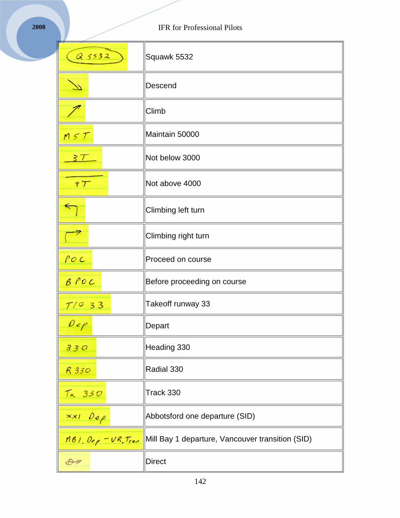
IFR for Professional Pilots
142
2008
Squawk 5532
Descend
Climb
Maintain 50000
Not below 3000
Not above 4000
Climbing left turn
Climbing right turn
Proceed on course
Before proceeding on course
Takeoff runway 33
Depart
Heading 330
Radial 330
Track 330
Abbotsford one departure (SID)
Mill Bay 1 departure, Vancouver transition (SID)
Direct

IFR for Professional Pilots
143
Selair.selkirk.ca
Victoria tower, frequency 119.7
Victoria terminal, frequency 132.7
Vancouver departure, frequency 120.5
Vancouver arrival, frequency 133.1
Vancouver center, frequency 134.2

IFR for Professional Pilots
144
2008

IFR for Professional Pilots
145
Selair.selkirk.ca
Chapter 13 Cockpit Organization
The Five Ts The five Ts is a mnemonic designed to keep you organized when you pass a
beacon, VOR, or waypoint on an IFR flight. The five Ts are:
1. Time
2. Turn
3. Throttle
4. Track
5. Talk
You must get into the habit of performing the 5T procedure every time you pass a
station or waypoint. This means both while in cruise and when flying an IFR approach.
You will soon discover that some of the Ts are redundant in particular situations, but you
MUST develop the habit of doing them to prepare you for when they are all needed, such
as when flying an IFR approach.
To perform the Ts all you do is:
1. Time – press the right hand button on the ADF to start the stopwatch. In addition,
if you are in cruise write down the time over the station on your navlog. (Note:
you always start the stopwatch, even in cruise.)
2. Turn – turn the OBS and Heading bug to the new course and heading, and THEN
start turning the airplane.
3. Throttle – if a change in altitude is required adjust the power. If no change in
altitude is called for then this T is redundant.
4. Track – start watching the CDI or ADF needle so that you don’t shoot through
your track. If you did not turn to a suitable heading at step 2 then start
intercepting.
5. Talk – only AFTER you have done the first four Ts should you make any position
reports that may be required. If you are in cruise you will need to make an IFR
position report if you are not radar identified. The format for the IFR position
report is on the back cover of your CFS. If you are flying an IFR approach you
will have to report outbound or inbound.
The important thing to remember about the fifth T is to do it last – not first.
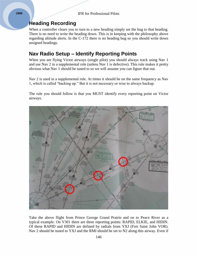
IFR for Professional Pilots
146
2008
Heading Recording When a controller clears you to turn to a new heading simply set the bug to that heading.
There is no need to write the heading down. This is in keeping with the philosophy above
regarding altitude alerts. In the C-172 there is no heading bug so you should write down
assigned headings.
Nav Radio Setup – Identify Reporting Points When you are flying Victor airways (single pilot) you should always track using Nav 1
and use Nav 2 in a supplemental role (unless Nav 1 is defective). This rule makes it pretty
obvious what Nav 1 should be tuned to so we will assume you can figure that out.
Nav 2 is used in a supplemental role. At times it should be on the same frequency as Nav
1, which is called “backing up.” But it is not necessary or wise to always backup.
The rule you should follow is that you MUST identify every reporting point on Victor
airways.
Take the above flight from Prince George Grand Prairie and on to Peace River as a
typical example. On V301 there are three reporting points: RAPID, ELKIE, and HIDIN.
Of these RAPID and HIDIN are defined by radials from YXJ (Fort Saint John VOR).
Nav 2 should be tuned to YXJ and the RMI should be set to N2 along this airway. Even if

IFR for Professional Pilots
147
Selair.selkirk.ca
you don’t have DME you can tell you are approaching the intersections by watching the
radials on the tail of the RMI. OBS 2 should be set to the defining radial. DO NOT take
the reciprocal, set the radial published on the chart. A rule that always works is that the
CDI on Nav 2 will deflect toward the VOR until you pass the reporting point, then it will
point away from the VOR.
ELKIE is defined as 71 DME from Grand Prairie. This appears to also be 71 from Prince
George, but ideally you should use Grand Prairie. To get the DME on Grand Prairie in
the Frasca 142 or King Air you must put Nav 1 on 113.1. Do this prior to 71 DME. In the
B-95 we could tune Nav 2 and set the DME to N2, but it seems an unwise plan since we
wish to have the RMI setup as described above. Therefore Nav 1 should be used to
identify ELKIE in all cases.
Once the airplane passes HIDIN normal practice is to backup Nav 1 by switching Nav 2
to Grand Prairie (YQU). As YQU is approached Nav 2’s OBS should be set to V329 to
go on to Peace River. Once past YQU the HSI’s OBS would be set to V329 and Nav 2
then becomes available to identify reporting points.
There are no reporting points between YQU and YPE so Nav 2 should be set to YPE. The
RMI could be on either N1 or N2, but N2 is preferred because it is usually better to have
the RMI indicate where you are going rather than where you have been.
Don’t Neglect the ADF
When flying Low frequency airways everyone makes good use of the ADF. There are a
few tips that I will cover shortly, but first I would like to say that you should not ignore
the ADF just because you are on a Victor airway, especially in the mountains or the
north.
There are lots of NDBs scattered around northern Canada and you should get into the
habit of tuning them as you fly by. This provides a backup confirmation that your VOR is
working properly and confirms the functionality of your ADF. Many pilots have flown
for hours to a destination in northern Canada that has only an ADF approach only
discover upon arrival that their ADF has failed. If they had been checking it enroute they
could have saved themselves a low-fuel emergency.
When flying low frequency airways you will be plagued by the inaccuracy of the ADF.
The needle will wander around and at times become quite unusable for navigation. As
GPS becomes more prevalent this problem will disappear, but there are still lots of people
flying with no GPS, so you need to develop proficiency at using ADF.
Be aware of the sources of ADF error such as mountain and shoreline effect and twilight
etc. These are discussed in detail in Avia 261 so we will not go into them here. Knowing
that these errors exist you must expect that the ADF needle will wander around as you are
navigating. The secret is to have patience when interpreting the needle. Paraphrasing an
old TV show, “truth is in there.” As the needle wanders around it points at the station plus
IFR for Professional Pilots
148
2008
some error. The error tends to be variable, so if you watch the variability and subtract it
out in your mind what is left is the truth, Sherlock) Of course this is easy to say and hard
to do. You will improve with practice.
An important principle of ADF navigation is that the ADF is more accurate when close to
the station. That should be a no-brainer. Therefore it behooves you to track accurately
outbound when you depart your destination and are close to the station. Once you
establish the heading that is keeping you on course don’t change it substantially enroute
even if the needle starts to wander around. Hold your heading until the destination beacon
comes into range. Of course it is crucial that you keep your heading indicator up-to-date,
so check the compass every 15 minutes.
Keep Track of Your Position
If you are using the navigation radios as described above you will always know where
you are. Have your LO or HI chart out and keep noting where you are on the chart. From
this you can determine the next frequency you will need. If you can’t put your finger on
the chart and say, “I am here” you are not doing your job properly.
Plan Ahead
After 30 years of teaching people to fly IFR I have noticed a surprising phenomenon.
Many pilots I have flown with do a terrific job as long as I sit beside them and every two
minutes say, “So what are you going to do next?” Sometimes it seems that I could just
send along a tape recorder with that question on it.
The first rule of IFR flying then is to keep asking yourself, “What should I do next?” If
you do this you will more than likely come up with a good answer; if not on your first
flight then by the time you have done three or four flights.
In many cases the best format to use in planning ahead is the five Ts. This is particularly
applicable when about 5 minutes from a VOR (or NDB) enroute, or during an approach.
When you ask yourself, “What should I do next?” you discover that you are approaching
a station and must do several things. In this case write yourself a script for the five Ts, but
be very specific. If you just say to yourself, “I will do the five Ts” that will do little good.
Instead use the Ts as a framework. You say, “Time: I will go outbound for 1:30, Turn: I
will set the heading bug to 265, Throttle: I will reduce manifold pressure to 18 inches,
Track: I will set the HSI and Nav 2 to 070, Talk: I will say Somespot tower GABC is by
the Somespot beacon outbound.” Notice the specificity of this script. If you do this you
will be well prepared to act when you pass the station.
As soon as you pass the station and complete the above script you would then ask
yourself, “What do I do next?” You would then plan the five Ts for inbound. And so the
process goes on and on for the entire flight.

IFR for Professional Pilots
149
Selair.selkirk.ca
The DME “HOLD” Feature The DME in both our airplanes and the simulator have a hold feature.
Occasionally you will need to use it, but it is a potentially very dangerous feature so it
bears examining in some detail.
To understand the hold feature you need to first understand the DME frequency
pairing system, which was covered in the text Navigation for Professional Pilots. Given
that every DME station is paired with a VOR or ILS of a particular frequency it would
just add extra weight and complexity to your airplane to have a tuner for your DME
radio. Instead your DME is tuned automatically when you tune a VOR/ILS.
In the case of the Frasca the DME is always tuned when Nav 1 is tuned. In the
case of the B-95 the DME can be switched between Nav 1 and Nav 2. This is also
explained in the simulation called “Tuning the DME” on of Professional Pilot IFR
website. The thing to remember is that you only have one DME, the N1/N2 switch only
changes which tuner is being used.
If you ever need to have your VOR on one station and your DME on a different
station you can see the problem. The hold function is the solution to that problem. You
can tune the DME, then select hold (HLD) this disconnects the DME from the nav radios.
You can then tune the VOR/ILS as desired without affecting the DME.
The problem is that there is NO INDICATION anywhere in the cockpit of what
frequency your DME is on. There have been a few fatal accidents where the pilot held the
DME from one station then forgot and used that DME for a descent on an IFR approach
and flew into the ground. This switch is widely accepted to be a “killer” so don’t use it
unless you have to. And, always identify your DME separately before an approach.
The RMI – Your Best Friend Perhaps the most useful instrument in the cockpit for maintaining an overall situational
awareness is the RMI. The RMI can be set to Nav 1 or Nav 2 and in the B-95 it can also
be set to GPS, which is a huge advantage. In the Frasca simulator you do not have the
option to set the RMI to GPS.
In the ALSIM the three RMI needles can be set to VOR or ADF. All of the needles can
be put on ADF. The green needle (on the HSI) can be put on ADF, VOR1 or VOR2. But,
the single needle can only be put on ADF or VOR1. The double needle can only be put
on ADF or VOR2.
The RMI displays your current radial under its tail, and the bearing to the VOR under the
arrow head. It is important to realize that RMI does NOT WORK with ILS. When you
tune an ILS the RMI needle goes to the right wingtip and parks there (i.e. it does
nothing.) If you have the option of switching to GPS do so. In the ALSIM you would put
the RMI on ADF during an ILS (unless you were presetting it for a missed approach
procedure involving a VOR.)

IFR for Professional Pilots
150
2008
An important use of the RMI is to get a quick bearing for an initial turn. For example if a
controller asks you to, “Go direct Whatcom” you can glance at the RMI (appropriately
tuned) and turn to the bearing indicated by the head. The trick is to keep track of which
needle is pointing at Whatcom.
In the days before DME and GPS it was standard practice to deploy the RMI to the VOR
that defines the next upcoming reporting point. The second OBS would also be set to this
intersection, but having the RMI acted like a “poor man’s DME” showing you closing in
on the reporting point.
In the event that a VOR signal is lost (i.e. the station goes off the air) the RMI should go
to the right wingtip, but in some cases it will continue to point at the last position. Be on
guard for this possibility. Check the ident if in doubt.
When the RMI is set to GPS (B95) it points at the active waypoint, which is in the upper
left corner of Super-nav 5 page. When you are in LEG mode the waypoint is always
ahead of you so as you pass each waypoint the needle swings telling you the new
direction to fly.
GPS Moving Map Since GPS moving maps became available in-flight disorientation has gone way down.
But even with a moving map pilots can become disoriented. Some famous accidents,
even at the airline level, have happened despite moving maps.
The first key to using the moving map involves knowing how to set it up. Know how to
turn VORs, airports, NDBs, etc on and off, and how to change the scale.
The scale setting depends on the airspace you are flying in. On approaches you should set
it to auto, but enroute that will result in far too large a scale so you must manually set it.
In busy airspace such as Vancouver terminal 7 or 10 miles is usually best. On longer
cross countries you may wish to increase the scale so that at least one or two VORs are in
range, so the scale should be approximately half the distance between VORs.
The map can be oriented to north up or track up. Track up is better in almost all cases.
Know how to change this.

IFR for Professional Pilots
151
Selair.selkirk.ca
Tune Setup Identify (TSI) In this section we will practice setting up the navigation and communications radios for
various scenarios. This will give us an opportunity to practice IFR flight scripting, i.e.
Kitchen table flying, as recommended above.
The method we will use is called Tune, Setup, Identify (TSI.)
The TSI system must become a ritual for you. If you use it all the time you won’t miss
anything. If you don’t you may be successful some of the time, even most times, but
occasionally you miss things. Sometimes the things you miss will be minor, but
occasionally you will make a major mistake. An example of this is having the
annunciator on GPS when it should be on Nav. If you don’t notice this your HSI will be
leading you on the wrong track. In an extreme case this could be fatal. Another example
that has been known to cause fatal accidents is not noticing that the DME is on hold. I can
pretty much guarantee that you will make mistakes relating to tuning and setup of your
radios. The question is not whether you will make mistakes but whether you will catch
the mistakes and correct them before a serious problem arises. Your commitment to
precisely following the TSI procedure is your best line of defense against the dangers of
mistuning radios.
It might seem unimportant to you what order tuning, setting up, and identification are
done in. In fact it sometimes isn’t important. That is part of the problem. Because pilots
can “get away with” doing things in any sequence a lot of the time with no apparent
penalty for this lack of discipline. Using TSI rigorously demands discipline on your part;
not unlike the life-discipline to eat right and exercise. It is often tempting to disregard
“eating right and exercising.” In the short term no penalty ensues, but in the long term
your health suffers. In the case of TSI the precise sequence only matters sometimes, such
as when a complex clearance must be responded to in a short time period. Examples
include: a last minute change of active approach, an emergency requiring immediate
landing (fire), incapacitation of the other pilot, etc. TSI can take you from zero to “good
to go” faster than any other sequence. If you are in the habit of using it you can handle
difficult situations without making a mistake. But if you normally setup in a jumbled
fashion that “gets the job done eventually” you may well miss something important under
pressure. It is precisely when you are stressed that you won’t notice that you are in GPS
mode when you should be in Nav, or OBS mode when you should be in LEG, or the
RNAV button is depressed, or the DME is on hold, or the wrong ILS frequency has been
tuned, etc. And keep in mind that even when there is no special pressure the highly
abstract nature of IFR flight makes it difficult to avoid occasionally missing something,
or setting some switch in the wrong position. TSI is your best insurance policy.
Hopefully you are convinced that TSI is a worthwhile discipline. The logic of tuning first,
then setting up before identifying is that you tune first because the radios can do nothing
until they are on the proper frequency. You setup before identifying because once the
setup is complete your mind can begin processing the image of your position and making
decisions about where to go. Identification is therefore the last step. There is never any

IFR for Professional Pilots
152
2008
controversy about tuning first, but some people feel they should identify before setup
because they know there is a “rule” that you must identify before you “use” a navaid.
An established principle is that you should not navigate with a radio until it has been
identified. But there are some exceptions to this, which we must discuss.
The only thing more dangerous than navigating with a radio that has not been identified is
not navigating at all. Common sense says that you can’t just fly off into “nowhere land”
in IMC conditions. So at times, if you have to switch to a new frequency and then begin
navigating by it right away, it may be necessary to start a turn while you are identifying.
Conversely, in the real world you are often in VMC conditions even though you are on an
IFR flight plan. If ATC requests you go to a navaid as soon as able you can tune and
setup the navaid and begin turning safely toward it while you identify. A key point in
both these situations is that you should know the approximate location of the navaid
anyway. Once you tune and setup the radio if it indicates a track in the direction you
anticipated a tentative identification has been completed and you can begin turning while
the formal identification is completed.
A further point to consider is that your mind needs time to process the abstract
information (deflection of CDI needle, relative position of RMI to HDG bug, etc.) By
setting up first you can begin figuring out what the instruments are telling you while you
identify. This will save a few (important) seconds.
IMPORTANT: despite the discussion above it is often the case that you should NOT turn
by reference to a navaid until it has been identified. You should be smart enough to figure
out such situations. In these cases delay turning until you have identified. Just because
you have done setup does not obligate you to turn.
The preceding paragraph is very important, note it carefully.
Tune - Run the Stack
A complete TSI involves tuning all the radios before setting up. We call this “running the
stack.”

IFR for Professional Pilots
153
Selair.selkirk.ca
Running the stack means going from top to bottom of the radios starting with the KLN
90b then com 1, com 2, Nav 1, Nav 2, and ADF. The spots you must fill include 1 active
GPS waypoint, 4 com frequencies, 5 Nav 1 frequencies, 2 Nav 2, and 2 ADF frequencies.
Once all these are set tune is complete.
The radio stacks for the B95 and Alsim are shown in diagrams below. In all cases it is
best to start at the top and work your way to the bottom. Once very radio, including
standby frequencies, has been tuned you are ready to move on to setup.
Setup: 3, 4, 5, or 8 things
Setup involves setting three, four, five, or eight items after tune is complete. The number
of items is different in different airplanes. In the case of the Frasca 142 panel shown
above there are four things to setup. These are:
1. Annunciator panel
2. HSI
3. Nav 2
4. RMI

IFR for Professional Pilots
154
2008
The above diagram is a schematic of the Radios in the B-95. It is quite similar to the
Frasca 142, but there are a few differences. For one thing there are five things to setup:
1. Annunciator
2. HSI
3. Nav 2
4. RMI
5. DME
It is important for you to go through the setup procedure in the same sequence each time
and never skip anything even if you know it is already OK, just say, “Good, good, good”
as you skim over items that require no change. But you will be surprised how often you
notice that you need to change something (that you would have missed without this
framework.)
For the Alsim there are 8 things for the PNF to setup and 7 things for the PF to set. The
Alsim setup is described below, and should be practiced extensively using the Alsim
simulation. The Alsim setup is much more complex than either of the above two and will
require a great deal of concentration on your part.

IFR for Professional Pilots
155
Selair.selkirk.ca
Identify
The last step in TSI is identify, for this use the audio panel as your guide. All Selkirk
College airplanes use the KMA 24 audio panel. The recommended procedure is to run
across the audio panel from left to right. The Alsim audio panel is slightly different but
works essentially the same way.
Abbreviated TSI
In a complete TSI you run the stack first, i.e. tune ALL the radios, then all the setup items
and then identify the radios by moving across the audio panel from left to right.
There are some situations in which a complete TSI is not feasible, for example a
clearance such as, “GSAK go direct the WC now.” In this case common sense dictates
that we not waste time tuning the GPS, Nav 1, and Nav 2 before tuning the ADF. Instead
simply do an abbreviated TSI on the ADF only. I.E. tune the ADF, setup the RMI switch
and identify the ADF. Two important points must be made here:
First; in the Frasca 142 and B-95 setup there is no setup required for the ADF radio. But
in the King Air the RMI switches must be set to ADF. It is vital that you develop the
discipline of mentally acknowledging the setup step in the Frasca 142 and the B-95 by
simply saying to yourself, “nothing to setup.” The two seconds taken are worth it to
implant the TSI principle in your mind and will stand you in good stead when you fly the
King Air and other airplanes in the future.
Second; when you do an abbreviated TSI on one radio make a mental note that you “owe
yourself” a complete TSI. Any change in navigation reference warrants a complete check
that everything is set the way you want it as soon as workload permits. It is often
necessary to do a limited TSI as described here, but run the stack and check all setup
items as soon as you can afterwards.
TSI for Frasca 142 As you run the stack the details to keep in mind in the Frasca 142, in order, are:
Check the active waypoint on the GPS (Nav 5 page is assumed)
Tune both an active and standby frequency on com 1
Tune both an active and standby frequency on com 2
Confirm all 5 memory frequencies are as desired on Nav 1
Select an in use frequency
Check RNAV / VOR buttons are as desired
Confirm HOLD is not selected (unless desired)
Tune active and standby frequency on Nav 2
Tune active and standby frequency on ADF
Set clock display as desired on ADF
Set ADF / ANT switch to ADF
IFR for Professional Pilots
156
2008
Once you have run the stack as described above perform the four item setup. Annunciator
and HSI have sub-items:
1. Annunciator
Select GPS or Nav as needed
Select LEG or OBS as needed
2. HSI
Set heading bug to current or new heading
Set OBS to desired course
3. Nav 2
Set desired course
4. RMI
Select Nav 1 or Nav 2
After the setup complete identification by going left to right on the audio panel. Set
marker audio as desired. Identify Nav 1, Nav 2, DME, and ADF in that order. To identify
the ADFs push the button in. If more than 5NM from the station use the ANT setting to
identify and perform a test by observing the needle swing as ANT and then ADF are
selected.
TSI for Beech 95 As you run the stack the details to keep in mind in the B95, in order, are:
Check the active waypoint on the GPS (Nav 5 page is assumed)
Tune both an active and standby frequency on com 1
Tune both an active and standby frequency on com 2
Tune active and standby frequency on Nav 1
Tune active and standby frequency on Nav 2
Tune active and standby frequency on ADF
Set clock display as desired on ADF
Set ADF / ANT switch to ADF
Once you have run the stack as described above perform the four item setup. Annunciator
and HSI have sub-items:
1. Annunciator
Select GPS or Nav as needed
Select LEG or OBS as needed
2. HSI
Set heading bug to current or new heading
Set OBS to desired course
3. Nav 2
Set desired course
4. RMI
Select Nav 1, Nav 2, or GPS
5. DME
Set to N1, N2 or occasionally to Hold
IFR for Professional Pilots
157
Selair.selkirk.ca
After the setup complete identification by going left to right on the audio panel. Set
marker audio as desired. Identify Nav 1, Nav 2, DME, and ADF in that order. To identify
the ADFs push the button in. If more than 5NM from the station use the ANT setting to
identify and perform a test by observing the needle swing as ANT and then ADF are
selected.
The differences between the B-95 and Frasca 142 are:
1. There is no RNAV therefore Nav 1 setup is simpler
2. RMI can be set to GPS as well as N1 and N2 ( a big advantage)
3. DME must be selected. (not always on N1 as in Frasca 142)
TSI for Alsim As you run the stack the details to keep in mind in the Alsim, in order, are:
Check the active waypoint on the GPS – set OBS mode as desired
Tune both an active and standby frequency on com 1
Tune both an active and standby frequency on com 2
Tune active and standby frequency on Nav 1
Tune active and standby frequency on Nav 2
Tune active and standby frequency on ADF
Set clock display as desired on ADF
Set ADF / ANT switch to ADF
To perform the tune, setup, identify procedure on the Alsim without missing anything
you must know how many items require setup, and where they are.
There are 8 items to check/set for the PM and 7 for the PF.
Pilot Flying setup:
1. HSI
2. Primary RMI
3. single needle RMI
4. double needle RMI
5. Annunciator – check and set CDI
6. Course
7. HDG bug
Pilot Monitoring setup:
1. HSI
2. Primary RMI
3. single needle RMI
4. double needle RMI
5. Annunciator – check and set CDI
6. Course
7. HDG bug
8. DME selector
Options:
1. HSI [Nav1 / Nav2]

IFR for Professional Pilots
158
2008
2. Primary RMI [VOR1, VOR2, ADF]
3. single needle RMI [VOR1, ADF]
4. double needle RMI [VOR2, ADF]
5. Annunciator – [GNSS if HSI on NAV1 and GNS430 CDI button on GPS, else
NAV1 OR NAV2]
6. Course [course bar on HSI, set as required]
7. HDG bug [set desired heading]
8. DME selector [N1, N2, H1, H2]
Practice the above TSI using the Alsim Simulation.

IFR for Professional Pilots
159
Selair.selkirk.ca
Scripting Principles Now that we have the TSI procedure and have explored recommendations for using the
navigation radios to maintain situational awareness it is time to do some practice scripts.
We will examine several example scripts with commentary intended to reveal the authors
view of what the most effective setup is.
First let’s examine a few further principles to keep in mind about scripting IFR flights.
Flexibility in Scripting
There is more than one effective way to setup the radios for most IFR situations. The
examples that follow represent the ideas of only one pilot and there is no intent to
indicate that they represent the only acceptable setup.
While there are several good setups available in most situations that is not the same as
saying that any setup is good. As much as possible I will mention alternate good options
and point out commonly used but poor setups. The objective is to get you thinking about
the options and developing your own style (yes, there is such a thing as style).
Single-Pilot Scripts
There can be a significant difference in the best setup depending on how many pilots
there are and whether or not they have an autopilot. This relates back to aviate, navigate,
and communicate principle. A single-pilot with no autopilot should put a premium on
setups that won’t require much changing, especially during busy portions of the flight.
Every time a single-pilot must change a radio, concentration available for aviating is
reduced.
The greatest concentration on aviating is required during departure and approach and
therefore these are the stages of a flight in which it is important to choose a setup that
requires no more changing than necessary. In the enroute phase of flight the airplane
should be trimmed for cruise and quite stable. Making radio setup changes at this stage is
comparatively easy, so everything that needs to be done, such as weather checking,
RAIM predictions, WAT and AMORTS, etc should be taken care of in cruise.
For departure setup a single-pilot is well advised to setup for what will be needed rather
than what could remotely be needed. This is obvious when stated like this, but many
pilots like to setup the radios for an emergency return to the airport in case there is an
engine failure on departure. This is laudable concern but a relatively unlikely probability.
If a complex departure must be flown single-pilot it is much wiser to setup for the
departure and enroute; setup for an emergency return with radios that are “surplus”.
Maximum Information or Required Only?
If you are taking off on a runway with an ILS should you tune the ILS?
When taking off should you tune the active ILS and IAF beacon?
IFR for Professional Pilots
160
2008
Enroute, should you identify every intersection?
When flying an ILS with no DME should you hold the DME on a different frequency?
When flying an ILS approach should you setup the GPS moving map for the same track?
When flying an ADF approach should you tune a nearby VOR?
The answer to all these questions could be either yes or no. In each case the pilot must
decide whether the added information is worthwhile.
In the section on Single-pilot scripts above I said you should setup so that no changes are
needed during departures and arrivals, if possible. This conflicts with the idea of getting
as much information as possible. The single-pilot should probably not tune the ILS for
departure for example. On the other hand s/he normally should identify every intersection
enroute, but might have to forgo this if time is needed to check weather or deal with an
emergency. The decision would have to be made in the context, including whether or not
the airplane is radar identified.
When there are two pilots, as in the King Air, then pilots should lean toward getting
maximum information. In this case tuning the ILS on departure is good. The frequency
can be quickly changed by the pilot monitoring when needed.
To Backup or Not to Backup
The issue of backing up in your setup is a matter of redundancy. Airplanes have two
engines, two alternators, two vacuum pumps, etc for redundancy. If one fails the other
takes over and no harm is done. The same applies to radio setups. When flying an ILS
tune both radios to the ILS. When doing an ADF approach tune both ADF radios to the
beacon, etc.
A mistake that is sometimes made is to backup the wrong thing. For example on an ILS
the ADF is used to identify the glidepath check point (usually the FAF). This may be
backed up with a DME, but if DME is not available it could also be backed up with a
VOR cross-radial. However, to do so would mean not backing up the localizer and
glidepath. Common sense should tell us that this is not good backing up.
Avoid Flags and Red Lights
When a red flag extends on a VOR or GPS it means something is wrong – usually. But it
could just be that the station is out of range. Therefore on departure it is often the case
that a red flag will appear on the HSI or VOR#2. What can we do about this; or should
we do anything?
It is a bad habit to get into, letting red flags remain unresolved on your panel. It breeds an
apathy that can get you into trouble. So, if there is a way to tune some other frequency so

IFR for Professional Pilots
161
Selair.selkirk.ca
that no flag shows you should do that. For example you may be able to switch from Nav
to GPS, or tune an ILS rather than a VOR that is out of range, etc.
Sometimes there is no way around this problem, so you have to accept the flag on the
ground. Try not to let it become a habit; but keep in mind what I said about setting up
what will be needed for a single-pilot departure – that could require a compromise on this
issue.
Adjusting to Equipment Failures
If you have a script (see below for more advice on this,) you know what you intended to
do with all equipment, and why. Having thought it through you will usually find it easy to
decide what you can do without if you must adjust to the failure of a radio. You will
know the situations in which a radio is necessary and request a change of clearance. For
example if you were going to do an ADF approach but now your only ADF radio has
failed can you continue to your destination?
Yes, if you have a script for setting up a GPS overlay; otherwise – no.
If you are going to do an ILS in which a beacon marks the FAF can you continue if your
only ADF has failed?
In most cases you can. There may have scripted a DME backup, or have considered a
VOR cross radial, or if you are in radar contact that can be substituted. If you have a good
script you would know this and have little trouble deciding whether to continue or not
and what script changes are needed.
Kitchen Table Flying As we near the end of this text I am about to reveal to you my most valuable peace of
advice. I am not kidding; this simple concept is my best advice, so don’t blow it off.
I have said that you should develop a script as part of your preflight planning for every
IFR flight. This obviously involves looking over all the relevant charts, especially the
SID, and approach plates as well as examining the LO chart. Once you have looked them
over and think you understand everything, try this exercise.
Sit at the Kitchen table and pretend you are in the cockpit. The first few times you try this
have several blank copies of the relevant radio templates from the appendix in front of
you, but once you get good at it you will just do it in your head.
Start by saying, what clearance do I expect? If you can’t anticipate your IFR clearance go
back to the beginning and start over because you are nowhere near ready to fly IFR.
Now assume you got the required clearance – do TSI as you will for takeoff. Completely
fill in the blank form (later you will just memorize your choices).

IFR for Professional Pilots
162
2008
Next; ask yourself, when is the first time I will need to change any of these items (even
the slightest change)? Think it through carefully because this is perhaps the most telling
test of your ability to create a script. I am quite confident that with a moment or two of
reflection you will be able to specify exactly when you will need to make a change.
Next, assume you are at the specified location and repeat TSI again. Then ask yourself
when the next change will be. Repeat this over and over; you will eventually get to the
end of the flight (i.e. end of the script), but there is one complication.
The complication is that in some cases you will realize that a change point the flight
could proceed this way or that way. EXCELLENT, you have identified a DECISION
point that you will have to make in flight. Obvious examples include which approach you
will do at the destination but there are others, such as whether or not you will get this
STAR or that STAR, etc.
When you recognize a decision point as described above you MUST follow each
reasonable scenario. i.e. pick one and go through TSI for that and follow it through to the
end of the flight – and then come back and pick the other option(s) and follow them
through to the end, until you cover all possible.
How long will it take to do the above? From my experience it often takes a beginner at
longer to Kitchen fly a trip than it will to actually fly it; in other words it may take you
two hours, sometimes more, for a 1.5 hour flight. The reason it takes so long is that you
will find yourself dithering about whether you should set this or that and you will have to
lookup a lot of information on the approach plates that you previously thought you had
reviewed but now realize only scanned in a far too superficial way. There are two ways
you could react to putting so much time into this Kitchen table flying idea. You might say
“no way am I going to do this”; it is completely unrealistic to spend two hours reviewing
material for a flight. I’ll give you my thoughts on that, but please reflect on what you
think before reading the next paragraph.
I agree that it is totally unrealistic to spend two hours reviewing charts for a professional
IFR pilot. But it is ridiculous to think that if it takes you two hours to figure out what to
do when you aren’t even being burdened flying that you are going to do anything but
make a fool of yourself if you go flying. As a student you need this much time to prepare
for an IFR flight (or simulator session).
Kitchen table flying is the most valuable exercise you can undertake as a student of IFR
flying. It is the equivalent of an Olympic runner putting in miles of training so s/he can
run a 10 second race. You won’t need to do Kitchen table flying anymore when you can
do it so fast that you could just as easily do it in flight. But I GAURANTEE that you will
be far too slow the first 20 or 30 times you do it. So I will be trying to force you to do it
in class, and begging you to do it before simulator sessions, so that when you finally fly
IFR for real you have no hesitation about what you want to do. It won’t be long once you
are on the job before you pass this idea by, but it will be an important step to getting
there.

IFR for Professional Pilots
163
Selair.selkirk.ca
The Ultimate Kitchen Table Flight
I’m not done yet.
In the above I only talked about “kitchen flying” the radio setups. But there are clearly
other aspects of a flight that can be scripted. I have found that scripting configuration and
power changes is a terrific benefit to beginning IFR pilots. The best way to do this is to
script all 5T situations as part of your kitchen flying script.
When you know your configurations and power setting so well that reviewing them is
redundant you can stop.
IKEA Kitchen Tables
IKEA tables come in pieces that you have to put together. So do IFR flights. If you script
a flight from Castlegar to Kelowna and on another day script one from Cranbrook to
Kelowna the last 2/3 of the flights are the same. So if you have a good memory you are
done in a jiffy.
Scripts come in modules. Once you have a script for a departure from Vancouver you can
use it for a flight to anywhere. You get the idea.
So think of your scripts in modules and build a library of useful ones in your memory.

IFR for Professional Pilots
164
2008
IFR for Professional Pilots
165
Selair.selkirk.ca
Chapter 14 Briefings
IFR Clearance Review
Prior to giving a takeoff briefing you need to review your IFR clearance. In the C-172
and B95 checklists we have put clearance review in as an item just before the briefing (to
remind you) but in the Alsim it is assumed that the captain will review the clearance
while waiting for the co-pilot to complete his/her flows.
Organize your clearance review into 3 steps:
1. Read the clearance checking that it is valid and acceptable to you
2. Visualize the assigned route by tracing it out on the maps and charts.
3. Formulate a radio setup plan – and then set it up if single pilot or brief the PNF
what you need if two-pilot.
Step one is self explanatory – but make sure to check for a valid clearance including an
assigned altitude and an EFC time if cleared short.
Step two is the most important step. As you trace the route out concentrate on the first 5
minutes of the flight. Determine what heading you will fly after takeoff and when the first
turn will be. Determine whether the turn will be left or right and if possible what heading
you will turn to. Determine what altitude you are cleared to initially (set altitude alerter)
and when you can expect higher.
Step 3 will go easily if you did step 2 properly – just make sure to set all the radios,
starting at the top and “running the stack” (see previous chapter.)
Takeoff Briefing
The need to give a takeoff briefing was previously mentioned under the topic of
Maintaining Situational Awareness. It is important to remember in all the briefings
described in this section that their purpose is to improve the crew’s situational awareness.
In the case of a single pilot, briefing may not be the correct term, since it is usually done
silently, but the formal process serves the purpose of establishing mental alertness with
the intent of reducing the chances of neglecting an important detail or reacting too slowly
to an anticipatable emergency.
A takeoff briefing normally contains three elements:
1. Description of takeoff, including operational speeds

IFR for Professional Pilots
166
2008
2. Description of departure route
3. Emergency responses
Item 1 normally involves describing the type of takeoff to be performed and reviewing
the “V speeds.” This material is outside the contents of this course so it will not be
discussed further here.
Item 2 is the primary concern of this course. The pilot(s) should have reviewed the
clearance, following the three-step procedure described above. The review is normally
done silently. As it is a scripting exercise it proceeds from beginning to end, and thus the
elements most present in the pilots mind are the later ones, when it is the first ones that
need to be emphasized. Therefore, in the briefing the pilot flying should emphasize those
elements of the script that apply in the first moments of the flight. Exactly how far into
the flight to brief is a matter of judgment, but usually more than two or three minutes is
too much. The briefing should always include:
Cleared altitude
Special ATC or procedural restrictions
Unusual maneuvers required
The cleared altitude is frequently different than the flight plan altitude, which makes
mistakes easy. Therefore the cleared altitude should always be emphasized in the
briefing.
Special ATC or procedural restrictions include items such as VFR climb restriction, a
request to contact a frequency other than the one published on the departure chart, the
need to fly a climb gradient other than 200 ft/NM, etc.
It can be a matter of judgment what constitutes an unusual maneuver. Most pilots would
agree that any turns that must be initiated before a trimmed cruise climb is established are
unusual, and therefore should be briefed. Someone once said, “I can’t define art, but I
know it when I see it.” Unusual maneuvers are like that. If the departure requires you to
do something you seldom or never do it is unusual by definition and therefore requires
specific briefing.
In the above discussion the word briefing implies a conversation, and therefore two
pilots. But it is important that when flying single-pilot-IFR you brief yourself. You
probably will do it silently, so the passengers don’t think you’re off your rocker. But it is
still an important exercise in mentally preparing for flight.
Many pilots, with the approval of the companies they work for, make use of abbreviated
briefings in which words such as, “normal procedures” or some similar terminology is
used to shorten the takeoff briefing. This can be a good idea or a bad idea depending on
the details and the mental attitude of the pilots who use it. It is a good idea because
repetitive briefings on a series of flights in a single work day tend to promote apathy and
lack of attention. On the other hand, if briefings are ALWAYS stripped of details,
IFR for Professional Pilots
167
Selair.selkirk.ca
perhaps because we assume we have them memorized, after weeks or months of flying
we are not mentally alert and safety is compromised. Therefore I recommend that for the
first takeoff each day a full briefing is done. On subsequent takeoffs, with the same crew,
(single-pilot is always the same crew ) the briefing can be shortened provided the same
conditions apply.
When a briefing is shortened, as described above it is normally part 1 and 3 that are
shortened. Only if the crew is doing the same route several times in one shift can part 2,
the description of departure route be dropped.
WAT WAT is an acronym that may be used to mentally organize for the approach enroute to an
IFR destination. The WAT briefing is normally completed as a lead in to the AMORTS
briefing. Ideally it will be completed prior to initiating descent. However, the items
included in a WAT briefing should be given consideration prior to departure and
continually revisited enroute. These items allow you to formulate a plan and anticipate
the arrival procedures based on relevant and updated information (weather, anticipated
delays, NOTAM, etc). This mental preparation is essential to a smoothly executed arrival.
In a two-pilot operation WAT should be included as part of the formal approach briefing.
The letters stand for:
W – Weather
A – Approach
T – Temperature
W. Check the weather, NOTAMs, and PIREPs for your destination, alternate, and
enroute. Update this information periodically in cruise. You can get this from ATIS if
available but you may need to call FSS. When requesting updated weather form FSS, ask
for the latest METAR and any amendments to the last TAF you have in your possession.
If things have changed unexpectedly or drastically, consider requesting a more thorough
update. Ask yourself these questions about the current and forecast weather?
What runway do I anticipate using? Considerations (winds, runway length and condition)
Will it be a circling or straight-in approach?
Is the ceiling and visibility above or below approach minima?
What do I expect to see at DH or MDA? (type of approach lights, runway alignment)
What are the chances of success?
What will I do in the event of a missed approach? (try another approach, or request
clearance to the alternate)

IFR for Professional Pilots
168
2008
A. Review potential arrivals and approaches for your destination and alternate.
Determine which approaches you are able to do (i.e. which you have the equipment for.)
Determine which has the lowest minima, and which have minima lower than the reported
weather. Finally decide what your preferred or anticipated approach is. Ask yourself
these questions about the available approach procedures?
What are the available procedures? (consider wind, weather, NOTAM outages, aircraft
equipment, active runways)
Which procedure has the highest likelihood of success?
Which procedure will be most efficient? (least amount of maneuvering, shorter taxi, etc.)
When will I need to start the descent? (crossing restrictions, etc.)
Does the procedure require a non-standard radio setup?
T. Consider the temperature at destination and the alternate. If the field temperature is
0°C or below cold temperature altitude corrections are required. Consider making these
calculations prior to departure if the flight is short. Always apply these corrections prior
to starting the approach briefing.
WAT makes a good planning ahead format to help you develop a script prior to
completing the actual briefing. As you plan ahead and are trying to answer the usual,
“What should I do now?” question you can use WAT to help you decide if you have
forgotten anything. In a two-pilot environment the WAT items will be included as part of
the approach briefing. This is not to say you will verbalize all the preceding questions,
but once they have been considered you will formally brief the relevant points.
Refer to the professional pilot website for an example of a typical WAT briefing in video
and textual format. (Pilot Training→Alsim Page→Two-Piot CRM Videos→Two-Pilot
ILS Approach)
AMORTS Although formalized approach briefings are the industry standard for professional pilots,
the specific form varies with operator. It is important to adopt a systematic approach to
the briefing to ensure nothing is missed. This may seem onerous at first, but in time you
will be familiar enough with the format that it becomes automatic.
AMORTS is a common industry acronym that helps you get organized before flying an
IFR approach. You will perform an “AMORTS approach briefing” prior to commencing
every IFR approach. Once you have considered WAT you are ready to complete an
approach briefing. During operational single pilot flights this briefing will typically be
completed silently. During a single pilot instructional lesson in the simulator the
IFR for Professional Pilots
169
Selair.selkirk.ca
instructor will expect to hear the approach briefing in order to evaluate its content, and
efficiency.
The letters stand for:
A – Approach
M – Minima
O – Overshoot
R – Radios
T – Timing
S – Speeds and special considerations
The acronym ensures that you will cover all important aspects of the approach before
doing it. It is not a substitute for having reviewed the approach thoroughly before the
flight however. It is important that you have analyzed the approach as described
elsewhere in this manual before the flight. If not you should silently do that analysis
before attempting an AMORTS briefing.
AMORTs briefings will be performed out loud in a multi-crew situation.
A. The approach section ensures all crew members are referencing the correct material.
Name the approach
State procedure effective date
State the airport elevation or touchdown zone elevation if applicable
State the name of the approach and whether or not you will fly a full procedure, or a
straight-in. If straight-in state the method of intercepting final.
State intentions to circle and runway if applicable.
Next read the effective date (bottom of page.)
Next read the airport elevation or touchdown zone elevation if applicable (top right
corner of the plate)
M. This portion of the AMORTs will be the most involved. It is simply a step by step
review of what is required to complete the procedure from top of descent until DH or
MDA is reached. It is a chronological overview of the procedure including:
Top of Descent
Minimum safe altitudes as they apply chronologically
Crossing/speed restrictions
Plan to transition into the approach (when to turn to intercept the arc, what type of
procedure turn with applicable timings/distances, vectors, etc.)

IFR for Professional Pilots
170
2008
Constant descent point
Required tracks
Altimeter bug setting if applicable
Only relevant minimum altitudes need mentioning. (ie: if there are more than one sector
altitude, only the applicable sector needs mentioning)
Normally the initial safe altitude is the MEA for the airway you are on. But, if you are not
on an airway then you must use the 100-mile safe altitude, or the 25NM safe altitude. To
use either of these you must confirm you are within the specified distance.
O. The proper term for this segment is missed approach. An overshoot is a visual
maneuver. Unfortunately AMMRTS doesn’t roll off the tongue too well so we use the
word overshoot to remind us of the missed approach procedure.
The pilot normally reads the entire missed approach procedure. For a non-precision
approach ensure to mention the missed approach point and how it is identified. One extra
piece of information should be added if not included in the written procedure and that is
the direction of the first turn. The only possibilities are “straight ahead”, “left turn,” and
“right turn.”
During single-pilot operations it is advisable to MEMORIZE the initial step of the
procedure. During the initial stages of the missed approach you need to concentrate on
adding power, pitching the nose up and retracting flaps and gear. You don’t have time to
look at the plate. Therefore you must know whether to continue straight ahead or turn.
Emphasize this when you read the procedure.
Remember you have already considered the weather and are aware of the chances of
success. A missed approach is rarely a surprise.
R. This part of the briefing specifies the navaids required for the procedure. Only non-
standard radio setups need to be included in the briefing, other communication or
direction regarding radio setup can take place informally outside of the briefing.
Remember to use TSI (Tune setup identify) as a framework to keep you from forgetting
anything about the radio setup.
T. If the missed approach point is based on timing brief the time here, if the MAP is
based on distance (DME or GPS) state “timing, not applicable”.
S. Speeds and special considerations are briefed at this point. Only Vref and any non-
standard speeds need mentioning. Set applicable speed bugs at this time.
Special considerations refer to any applicable cautionary notes found on the approach
plate, and any other items which need special attention ( runway condition, crosswind,
circling restrictions, non-standard configuration, short field landing technique, etc.).

IFR for Professional Pilots
171
Selair.selkirk.ca
Refer to the professional pilot website for an example of a typical WAT briefing in video
and textual format. (Pilot Training→Alsim Page→Two-Piot CRM Videos→Two-Pilot
ILS Approach)
The form on the next page may be useful to you in giving a briefing in flight. Make
several copies of it and carry it on the flight. Fill in information such as ATIS when
received. Jot notes to yourself – even prior to the flight – and your briefing will go much
better.
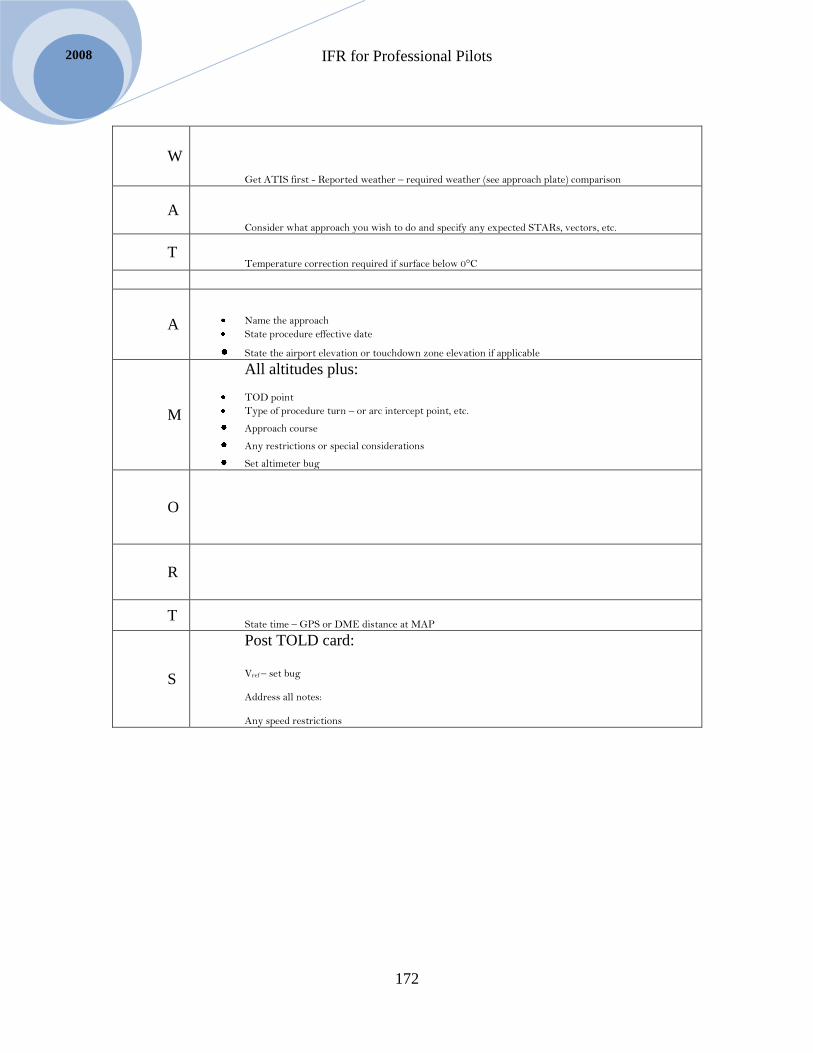
IFR for Professional Pilots
172
2008
W
Get ATIS first - Reported weather – required weather (see approach plate) comparison
A
Consider what approach you wish to do and specify any expected STARs, vectors, etc.
T Temperature correction required if surface below 0°C
A
Name the approach
State procedure effective date
State the airport elevation or touchdown zone elevation if applicable
M
All altitudes plus:
TOD point
Type of procedure turn – or arc intercept point, etc.
Approach course Any restrictions or special considerations Set altimeter bug
O
R
T State time – GPS or DME distance at MAP
S
Post TOLD card:
Vref – set bug Address all notes: Any speed restrictions

IFR for Professional Pilots
173
Selair.selkirk.ca
Chapter 15 IFR in Uncontrolled Airspace
Read RAC 2.0
This book started with a discussion about the roots of IFR flight and that it is possible to
fly IFR without air traffic control, as long as the number of airplanes in the system is
small. That is exactly the situation in northern Canada and as a result NavCanada has
chosen not to provide control service in NDA below FL230 and FL270 in the ACA. In
other words, if you want to fly IFR at less than 23,000 feet in the north you will be
uncontrolled.
Read RAC 8.9
In many cases a portion of your flight will be controlled, while another portion is
uncontrolled. RAC 8.9 explains the rules about getting an IFR clearance before entering
controlled airspace. Remember that if you are cruising at any altitude below FL230 when
you cross the boundary into NDA you become uncontrolled at that point. Remember also
that if you are below 18,000 when that happens you also transition to a standard pressure
region. When do you change your altimeter to 29.92? Formulate your answer before
reading the next paragraph.
You always change the altimeter in the standard pressure region. I.E. after leaving SDA,
or prior to entering SDA (below 18,000’). CAR 602.37 RAC 2.11
Read RAC 1.9.2 and CAR 605.35
What transponder code should you squawk when uncontrolled IFR? Formulate your
answer before reading the next paragraph.
If you are in high level airspace, i.e. uncontrolled from FL180 to FL220 in NDA or up to
FL260 in ACA squawk 2000; in low level airspace squawk 1000.
Read RAC 4.0
When flying uncontrolled IFR all the usual procedures for MF and ATF that you use
when you are VFR still apply (see RAC 4.0.) In addition you must report your intentions
on 126.7. This usually means that you will have to transmit your departure and arrival
intentions twice (once on the MF and once on 126.7).
IFR for Professional Pilots
174
2008
Sample Radio Calls for Uncontrolled IFR Flight – Yellowknife to Cambridge Bay
In this section I will present a set of simulated radio calls for an uncontrolled IFR flight in
a Navajo from Yellowknife to Cambridge Bay.
You need an LO 5 and CAP 1 to follow along. Notice that Yellowknife is in Southern
Domestic airspace but that transition to the northern domestic airspace will occur 50
miles into the flight. The flight will become uncontrolled from that point on.
A flight plan is filed the route is BR84 at 9,000’ asl.
Notice that a flight plan is only legally needed to PENVU, there will be no ATC
clearance beyond there, but if a full flight plan is not filed then a flight itinerary would be
needed. We will assume that the pilot prefers to have a flight plan, just like a VFR pilot
would. The flight plan must be closed after landing in Cambridge Bay (just like a VFR
flight plan).
To make it interesting I will include radio calls from several aircraft along the way in
order to demonstrate how uncontrolled IFR is done. The other aircraft will be identified
as aircraft 1, aircraft 2, etc.
Pilot: Yellowknife ground, Navajo GABC.
ATC: ABC Yellowknife ground, go ahead
Pilot: ABC on apron 1, IFR to Cambridge Bay at 9,000, ready taxi, with alpha
ATC: ABC roger, wind 240 at 10, altimeter 29.44, taxi bravo and Charlie, hold short 27. I
have your IFR clearance when you’re ready.
Pilot: 29.44, hold short 27. Go ahead.
ATC: ABC is cleared to PENVU intersection via Yellowknife One, flight plan route,
squawk 2461
Pilot: squawk 2461, ABC
ATC: roger
So far everything is exactly as we have been doing. This is to be expected because
Yellowknife is in controlled airspace, indeed a “bubble” of southern domestic airspace
surrounds it (check your LO5).
The pilot taxis out, and when ready for takeoff the following calls are required.
Pilot: Yellowknife tower, GABC is ready for takeoff on 27
ATC: ABC cleared takeoff 27, switch Edmonton center 135.8 through 1,000
Pilot: ABC
Note that no read back is required, although many pilots would.
The next call is to Edmonton after takeoff

IFR for Professional Pilots
175
Selair.selkirk.ca
Pilot: Edmonton center, Navajo GABC off Yellowknife runway 27, through 1,100 for
4,000.
ATC: ABC squawk ident.
Pilot: Squawk ident, ABC
ATC: ABC, radar identified, through 2,000 turn right heading 030 magnetic, vectors to
Bravo Romeo 84.
Pilot: through 2,000 right 030 magnetic, ABC
ATC: ABC, roger
This particular controller doesn’t want any mistakes so he tells the pilot that the vector
heading is magnetic. The pilot should not really switch to true headings until PENVU but
many pilots would actually set the true heading on the runway before takeoff northbound
out of Yellowknife. This is technically a no-no, because they are still in SDA until
PENVU.
After a minute or two:
ATC: ABC, maintain 9,000
Pilot: through 3,500 for 9,000, ABC
ATC: roger
A few minutes later
Pilot: Edmonton center, ABC level 9000
ATC: ABC, roger
After twenty minutes or so:
ATC: ABC approaching PENVU, maintain 9,000 in controlled airspace. Radar service
terminated, squawk 1000. Frequency change approved.
Pilot: 9,000 in controlled airspace. Switching, ABC
The pilot is now a few moments from entering northern domestic airspace. S/he should
do several things:
Switch the altimeter to 29.92 for the standard pressure region
Correct altitude to FL090 or whatever other altitude is desired
Broadcast location on 126.7
When should each of the above be done?
Switch altimeter setting is AFTER entering NDA, but a broadcast should be made now,
before entering uncontrolled airspace. The Navajo has two radios so the pilot leaves one
softly monitoring Edmonton center and using the other makes a call on 126.7
Pilot: Any traffic on 126.7, this is Navajo GABC on BR84 at PENVU, 9,000 at 1723
Zulu, IFR to Cambridge Bay, estimating LUPIN at 1840. Cambridge Bay next.
Airplane 1: something Charlie, I missed the ident. This is King Air GSEL 90 DME north
of Yellowknife on BR84 descending through 11,000 for 8,000. Say your DME.

IFR for Professional Pilots
176
2008
Pilot: This is G-A-B-C, at 52 DME northbound at Flight level 090.
Airplane 1: ABC roger, we will expedite descent through 9,000
Pilot: ABC roger, could you call me through flight level 090 with your DME
Airplane 1: Wilco
As is common, the King Air didn’t quite catch the ident but recognized a possible
conflict. Our pilot repeated his ident slowly. The King Air pilot could have simply leveled
at FL010 (I would think that would be the smarter thing to do – but he doesn’t even seem
to know that he isn’t at 11,000, he is at FL011) but instead asked ABC for a DME
distance and discovering they were still almost 40 miles apart decided to descend. We can
only wonder what s/he would have done had ABC reported “negative DME.”
Airplane 1: GSEL is descending through 9,000 at 80 DME.
Pilot: ABC roger, thanks.
The next reporting point is LUPIN, but since there is an IFR approach at LUPIN our pilot
should report about 15 minutes south of LUPIN in case there is someone arriving or
departing there that could be passing through FL090.
There are probably additional calls to Yellowknife and Arctic radio to check weather,
which I am not showing here.
Notice that our pilot has now entered NDA and changed the altimeter to 29.92. With that
done s/he must correct to FL090.
Our pilot will repeat the following call on 126.7 and then on LUPIN ATF 122.8
Pilot: LUPIN traffic, this is Navajo GABC on 126.7, 50 miles south of LUPIN at FL090,
estimating LUPIN at 1723, Cambridge Bay next.
Pilot: LUPIN traffic, this is Navajo GABC on 122.8, 50 miles south of LUPIN at FL090,
estimating LUPIN at 1723, Cambridge Bay next.
Notice the slightly abbreviated format.
After repeating the above on 122.8 the following exchange might occur:
Airplane 2: GABC this is Conquest FXYZ on 122.8, taxing for departure at runway 01 at
LUPIN. Confirm estimating LUPIN at 1723.
Pilot: ABC, affirmative, 1723. I am at flight level 090.
Airplane 2: roger, I’ll call when I am ready for takeoff for a position update
This guy is obviously pondering whether he can get up and out of LUPIN before the
Navajo conflicts. The current time is 1709, so if he is going to depart with a 10 minute
separation he had better move it. And GABC better be accurate with his ETA

IFR for Professional Pilots
177
Selair.selkirk.ca
Our pilot should be monitoring both frequencies as s/he flies over, but the Conquest is
legally required to broadcast his departure intentions on both 122.8 and 126.7, so in
theory it is OK to be just on 126.7.
Three minutes later the following transmission is made on 122.8, then moments later on
126.7
Airplane 2: This is conquest FXYZ taxiing to position runway 01 LUPIN, departure IFR
northbound on BR84, climbing to FL250
Pilot: XYZ, this is ABC, I check your intentions, I estimate 35 miles south of LUPIN at
FL090.
Airplane 2: XYZ, roger. No conflict, I will climb northbound after departure
Pilot: roger, ABC
The Conquest pilot visualizes that the Navajo is still 10 minutes (just) south and that if
s/he departs northbound there is no conflict, it would NOT be a good idea to takeoff on
runway 19 in this case as the airplanes would get too close.
Airplane 2: LUPIN traffic, Conquest FXYZ off runway 01 through 2,000 for FL 250
Pilot: XYZ, this is ABC could you report through flight level 090 please.
Airplane 2: roger
Airplane 2: LUPIN traffic, FXYZ is through FL090 for FL250
By the way will the conquest be uncontrolled or controlled at FL250?
Pilot: Arctic radio, this is Navajo GABC on 126.7, over LUPIN at 1721, level Flight
Level 090, IFR to Cambridge Bay, estimating Cambridge Bay at 1856 Zulu, for an
approach.
Radio: ABC, Arctic radio, I check your progress report. No reported traffic.
The above IFR position report is standard – see the back cover of your CFS. Since there
is no “next” reporting point our pilot has said “for an approach” to clarify his/her
intentions.
The next report should be approximately 15 minutes before arrival at Cambridge Bay. It
will be very much like the procedure south of LUPIN.
The call must be made on both 126.7 and CYBC MF 122.1
Pilot: Arctic radio, this is Navajo GABC on 126.7, 50 miles south of Cambridge Bay,
level flight level 090, inbound for the NDB runway 31 approach. Standby
Pilot Arctic radio, this is Navajo GABC on 122.1, 50 miles south of Cambridge Bay,
level flight level 090, inbound for the NDB runway 31 approach, estimating Cambridge
Bay beacon at 18:57 Zulu.

IFR for Professional Pilots
178
2008
Radio: ABC, Arctic radio, I check your position. No reported traffic, altimeter 29.07,
wind light and variable.
If no air to ground advisory is available the pilot will have to fly the approach and check
the windsock and runway conditions before landing.
Even though the radio operator says, “No reported traffic” the pilot must broadcast all
intentions on both 126.7 and 122.1 just in case.
When should our pilot set the altimeter to 29.07?
The altimeter should be changed just prior to commencing descent from FL090 for the
approach. NOTE that if the pilot decides to “step descend” i.e. descend say to FL 050 for
a while prior to the approach then the altimeter should NOT be changed. Set the airport
altimeter setting once descent for the approach begins.
Pilot: Arctic radio, ABC is descending from flight level 090 for the NDB runway 31true
approach, estimating Cambridge Bay at 1857, estimate landing at 1909.
Radio: roger
Pilot: Arctic radio, ABC is by the Cambridge Bay beacon outbound.
Radio: roger
Pilot: Arctic radio, ABC is by the Cambridge Bay beacon inbound for landing runway 31
true.
Radio: roger, no reported traffic. Wind 330 at less than 5.
Pilot: roger
Pilot: Arctic radio, ABC is down and clear, request flight plan closed.
Radio: ABC roger, flight plan closed.
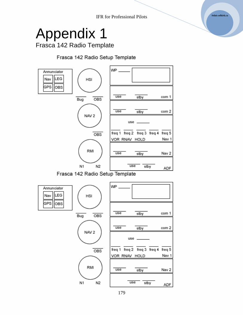
IFR for Professional Pilots
179
Selair.selkirk.ca
Appendix 1 Frasca 142 Radio Template

IFR for Professional Pilots
180
2008

IFR for Professional Pilots
181
Selair.selkirk.ca
Appendix 2 B95 Radio Template

IFR for Professional Pilots
182
2008
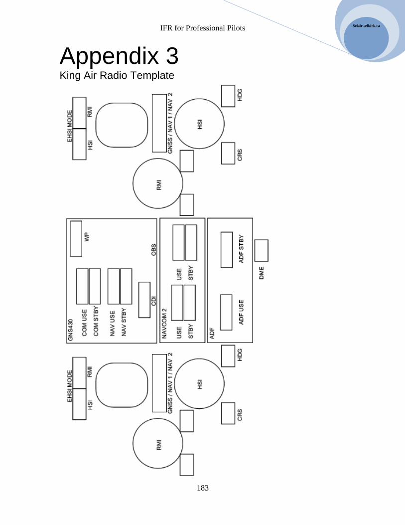
IFR for Professional Pilots
183
Selair.selkirk.ca
Appendix 3 King Air Radio Template

IFR for Professional Pilots
184
2008
Sample setup: ILS 08R at CYVR:

IFR for Professional Pilots
185
Selair.selkirk.ca
Sample setup: V300 at GOATE; Destination CYCG for LOC DME E APR