igbt for drives inkl ts600v outlook - home - faculdade …fdosreis/ftp/catalogos/igbt_drives...bas,...
TRANSCRIPT

Page 1
Drive and Control seminar 2003
Power Management& Supply
May 20031
F a s t ... F a s t ... H i g h S p e e d ... H i g h S p e e d ... T r e n c h S t o p ...T r e n c h S t o p ...
I G B TI G B T& D u o P a c & D u o P a c kk
TMTM
& E m C o & E m C o nnTMTM
DiodeDiode
Power Management& Supply
May 20032 Application frequency is the main selection criteria of IGBT
IGBT - Where to use...Different application frequencies require different IGBTs
Frequency
Application Requirements
Ultra high (>150 kHz)
low
high
low <12 kHz medium <40 kHz
Bipolar Transistor
MOSFET
IGBTs for:
Low Frequency
Applications
(e.g. drives,induction cooking)
Medium FrequencyApplications
(e.g. UPS)
HighFrequencyApplications
(e.g. SMPS,lamp ballast)
high <150kHz

Page 2
Drive and Control seminar 2003
Power Management& Supply
May 20033
Different switching frequencies require different IGBTs.Different switching frequencies require different IGBTs.
Pulse frequency typ. 2...16 kHz
(e.g. drives, induction cooking..)Pulse frequency typically 30..100 kHz (e.g. SMPS)
Conduction losses predominant! Switching losses predominant!
IGBT - Selection Depending on Application Frequency Application Specific Optimization
Low frequency applications: Higher frequency applications:
LO
W V
CE
sat
nee
ded
LO
W E
OFF
nee
ded
TrenchStop IGBT (600) / (1000) /1200V
High Speed (2) IGBT 600 / 1200V; LightMOS
Pulse frequency typ. 10...40kHz(e.g. UPS..)
Conduction and switching losses to be considered equally!
Medium frequency:
Fast IGBT600 / 1200V
EO
FFvs
. V
CE
sat
Power Management& Supply
May 20034
IGBT PortfolioToday
600V (Fast IGBT) Fast IGBT HighSpeed IGBT e.g. SKP06N60 e.g. SKP15N60 e.g. SKW20N60HS
1000V --- (not required) (not required)
1200V TrenchStop IGBT Fast IGBT HighSpeed2 e.g. IKW15T120 e.g. SKW25N120 e.g. IKW03N120H2
Application
Voltage
Low Frequency Medium Frequency High Frequencye.g. drives, ind. cooking e.g. UPS e.g. SMPS
Application
Voltage
Application
Voltage
Today, our portfolio covers main applications

Page 3
Drive and Control seminar 2003
Power Management& Supply
May 20035
Current Infineon IGBTs in Focus Applications
SK..06/10N60SK..15/20N60SK(G)..02/04N60
IKW25N120T
SGW10/20N60(HS)SGW25N120
IKW15T120 / IKW25T120
IGW03N120H2ILD(P)03N60(upcoming)
Application Infineon Device
Fast IGBT 600V DuoPack
TrenchStop 1200V DuoPack
High Speed 600V / Fast 1200V(depending on design)
Fast IGBT 1200V DuoPack (or Single)
HighSpeed2LightMOS(upcoming)
Product Family
Motor Drives e.g.- Wasching Machine- AirCon- Refridgerator /Dish W.
- Industrial Drives< 2.5 kW
UPS
Induction Cooking/Microwave
SMPSe.g. lamp ballast
Power Management& Supply
May 20036
IGBT Features and Benefits
Features and BenefitsIGBT Feature
Temperature stable
switching behaviour
Temperature stable
switching behaviour No thermal runawayNo thermal runaway
Lowest conduction losses
(TrenchStop IGBT)
Lowest conduction losses
(TrenchStop IGBT) Reduced need for coolingReduced need for cooling
Positive temp. coefficient of VcesatPositive temp. coefficient of Vcesat Easy paralleling also for 600Vdevices
Easy paralleling also for 600Vdevices
Non Punch Trough Technology:
Short circuit rated Avalanche rated
Latch -up free
Non Punch Trough Technology:
Short circuit rated Avalanche rated
Latch -up free
High ruggednessHigh ruggedness
High current density(TrenchStop IGBT)
High current density(TrenchStop IGBT)
Highest current class (60A single & 40A DuoPack)
Highest current class (60A single & 40A DuoPack)
Customer Benefit

Page 4
Drive and Control seminar 2003
Power Management& Supply
May 20037
Feature: Short Circuit RatedExceptional ruggedness of NPT and TrenchStop-Technology
Test Circuit :
Test Conditions :
TA=150°C
RG=56Ω; VDC=800V
VGEon=+15V; VGEoff= 0V
Short-circuit
Lσ
DUT2 0µ s
VDC
NPT and TrenchsTOP IGBT are short circuit proved due to the positive temperature coefficient in Vcesat
Short circuit IKW25T120
-20
0
20
40
60
80
100
120
140
160
180
0 5 10 15 20Time [µs]
Co
llect
or
curr
ent [
A]
-100
0
100
200
300
400
500
600
700
800
900
Co
llect
or
volt
age
[V]
UG E=0V U G E=15V U G E=0V
U C E
I C
10µs
10µs short:Successfulswitch-off
Power Management& Supply
May 20038
Avalanche ruggedness of High Speed IGBT
Single pulse rated IGBTs in NPT-Technology
Avalanche rugged devices :
• 600V Fast IGBT
• 600V High Speed IGBT
• 1200V Fast IGBT
(limited by pulse energy)
Avalanche rugged devices :
• 600V Fast IGBT
• 600V High Speed IGBT
• 1200V Fast IGBT
(limited by pulse energy)
Avalanche SGW20N60HS
-1
0
1
2
3
4
5
6
7
0 10 20 30 40 50Time [µs]
Co
llect
or
curr
ent
[A]
-200
0
200
400
600
800
1000
1200
1400
Co
llect
or
volt
age
[V]
UGE
=15V UG E
=0V
UC E
I C
600V device
Typical avalanche breakdown voltage
of 900V - 1000V
Feature: Avalanche RatedExceptional ruggedness of NPT and TrenchStop-Technology

Page 5
Drive and Control seminar 2003
Power Management& Supply
May 20039
Du
oP
ack™
15A
25A
40A
IKW15N120T
IKW25N120T
IKW40N120T
8A IKW08N120T
Sin
gle
IGB
T 8A
15A
25A
40A
IGW08N120T
IGW15N120T
IGW25N120T
IGW40N120T
60A IGW60N120T
Continuouscollectorcurrent
at T C =100°C
TO-247
IGW60T120 Best in Class
TO247
IKW40T120 Best in Class
TO247
Portfolio for Low Switching Frequencies (f <16kHz)TrenchStop IGBT 1200V
Power Management& Supply
May 200310
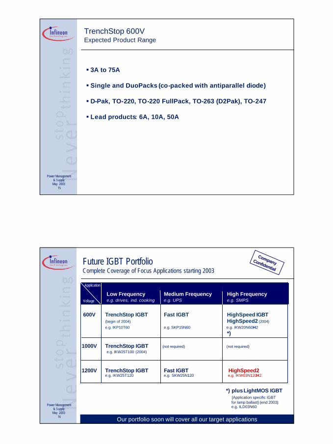
Future IGBT PortfolioComplete Coverage of Focus Applications starting 2003
600V TrenchStop IGBT Fast IGBT HighSpeed IGBT(begin of 2004) HighSpeed2 (2004)e.g. IKP10T60 e.g. SKP15N60 e.g. IKW20N60H2
*)
1000V TrenchStop IGBT (not required) (not required)e.g. IKW25T100 (2004)
1200V TrenchStop IGBT Fast IGBT HighSpeed2 e.g. IKW25T120 e.g. SKW25N120 e.g. IKW03N120H2
Application
Voltage
Low Frequency Medium Frequency High Frequencye.g. drives, ind. cooking e.g. UPS e.g. SMPS
Application
Voltage
Application
Voltage
*) plus LightMOS IGBT [Application specific IGBT for lamp ballast] (end 2003)e.g. ILD03N60
Our portfolio soon will cover all our target applications
CompanyCompanyConfidential
Confidential

Page 6
Drive and Control seminar 2003
Power Management& Supply
May 200311
0
10
20
30
40
50
1,4 1,6 1,8 2 2,2 2,4 2,6 2,8
Conduction losses [a.u.]
Sw
itch
ing
loss
es [a
.u.]
conventionalNPT IGBTs
PT technology range
Infineon TrenchStop
TrenchStop 600VTechnology: Target parameters, Benchmark vs. Competitors
SGP10N60A IGP10N60TVCEsat 150°C 2.4V 1.75V -27%
Eoff 150°C 0.34mJ 0.34mJ +/- 0%Eon 150°C 0.31mJ 0.28mJ -10%
Latest NPT devices offer good performance. 600V TrenchStop will
even outperform this and become benchmark in consumer drives.
Power Management& Supply
May 200312
TrenchStop 600VTechnology: Application requirements
PLUG
DC 1
PFC Controller
••
••
AC
85..
.380
V
D r i v e
µCon
trolle
r
CoolMOSTM / IGBT
EmConTM
TrenchStop IGBT
TrenchStop DuoPackTM
Consumer drives require:n Short circuit capability
(5µs, 15V Gate voltage , 400V Bus voltage)n Surge Current capability
(3x nominal current @ 15V Gate voltage)
TrenchStop – the DRIVES IGBT
Trenchstop 600V
ü
ü

Page 7
Drive and Control seminar 2003
Power Management& Supply
May 200313
TrenchStop 600VTarget markets
TrenchStop 600V is ideally suited for all drivesapplications with low switching frequency (6-16kHz)
Main target applications: Consumer drives & applications:Washing mashines / Dishwashers /
Refrigerators / Aircons /Microwave ovens / Induction cooking
etc.
Power Management& Supply
May 200314
TrenchStop 600VTechnology: Concept
TrenchStop
(Trench + Fieldstop)
n +
p+
GateEmitter (-)
Collector (+)
pEmitter
n-Fieldstop
n- wBas Bas,
p+
Fast IGBT
n+
p+ p
Gate
pEmitter
Emitter (-)
Collector (+)
n- wBas Bas,
The innovative TrenchStopIGBT concept is the next
evolutionary technology step
TrenchStop is the combination of Trench and FieldStop technologies
Page 8
Drive and Control seminar 2003
Power Management& Supply
May 200315
TrenchStop 600VExpected Product Range
§ 3A to 75A
§ Single and DuoPacks (co-packed with antiparallel diode)
§ D-Pak, TO-220, TO-220 FullPack, TO-263 (D2Pak), TO-247
§ Lead products: 6A, 10A, 50A
Power Management& Supply
May 200316
Future IGBT PortfolioComplete Coverage of Focus Applications starting 2003
600V TrenchStop IGBT Fast IGBT HighSpeed IGBT(begin of 2004) HighSpeed2 (2004)e.g. IKP10T60 e.g. SKP15N60 e.g. IKW20N60H2
*)
1000V TrenchStop IGBT (not required) (not required)e.g. IKW25T100 (2004)
1200V TrenchStop IGBT Fast IGBT HighSpeed2e.g. IKW25T120 e.g. SKW25N120 e.g. IKW03N120H2
Application
Voltage
Low Frequency Medium Frequency High Frequencye.g. drives, ind. cooking e.g. UPS e.g. SMPS
Application
Voltage
Application
Voltage
*) plus LightMOS IGBT [Application specific IGBT for lamp ballast] (end 2003)e.g. ILD03N60
Our portfolio soon will cover all our target applications
CompanyCompanyConfidential
Confidential

Page 9
Drive and Control seminar 2003
Power Management& Supply
May 200317
New HighSpeed2 IGBT (1200V) for “Fast Switching” Applications
HighSpeed2, the SMPS IGBT.
What’s new?• About 40% lower switching losses than conventional IGBTs in resonant topologies • About 15% lower price compared to high voltage power MOSFETs
Where’s it for?• For fast switching or resonant applications , e.g. SMPS for industrie drives , lamp
ballast, lighting ignition, DCM PFC, welding
What‘s available ?• 1A & 3A, 1200V IGBT• Qualification samples available ; production release in May 2003• Available in D2Pak, TO220 and TO247 packages and even in small DPak• DuoPack available (co-packed with antiparallel diode)
Power Management& Supply
May 200318
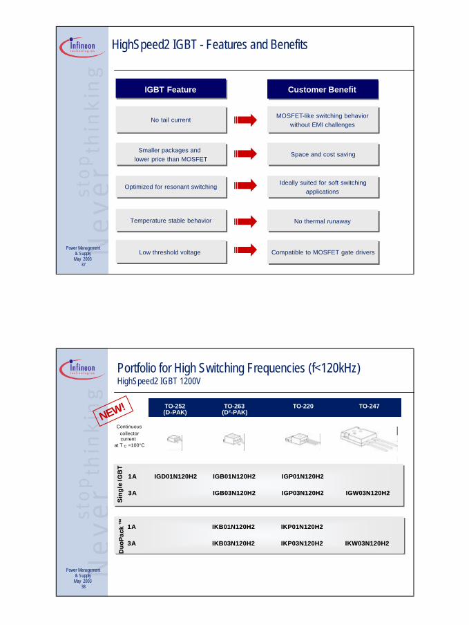
HighSpeed2 IGBT - Features and Benefits
Features and BenefitsIGBT Feature
Smaller packages and lower price than MOSFET
Smaller packages and lower price than MOSFET Space and cost savingSpace and cost saving
Temperature stable behaviorTemperature stable behavior No thermal runawayNo thermal runaway
Optimized for resonant switchingOptimized for resonant switching Ideally suited for soft switchingapplications
Ideally suited for soft switchingapplications
No tail currentNo tail current MOSFET-like switching behaviorwithout EMI challenges
MOSFET-like switching behaviorwithout EMI challenges
Low threshold voltage Low threshold voltage Compatible to MOSFET gate driversCompatible to MOSFET gate drivers
Customer Benefit

Page 10
Drive and Control seminar 2003
Power Management& Supply
May 200319
Portfolio for High Switching Frequencies (f<120kHz)HighSpeed2 IGBT 1200V
TO-252 TO-263(D-PAK) (D²-PAK)
Continuouscollectorcurrent
at T C =100°C
TO-220 TO-247
1A1A IGD01N120H2IGD01N120H2 IGB01N120H2IGB01N120H2 IGP01N120H2IGP01N120H2
3A3A IGB03N120H2IGB03N120H2 IGP03N120H2IGP03N120H2
Sin
gle
IGB
TS
ing
le IG
BT
IGW03N120H2IGW03N120H2
Du
oP
ack
™D
uo
Pac
k™
1A1A IKB01N120H2IKB01N120H2 IKP01N120H2IKP01N120H2
3A3A IKB03N120H2IKB03N120H2 IKP03N120H2IKP03N120H2 IKW03N120H2IKW03N120H2
NEW!
Power Management& Supply
May 200320
IGBT Roadmap
Time2002 2003 2004+
1200V
600V
Pulse Frequency
low
medium
high
TrenchStop8 - 60A
HighSpeed21 - 3A
Fast IGBT2 - 25A
low
high
medium
Fast IGBT2 - 30A
HighSpeed23 - 50A
TrenchStop3 - 50A
LightMOS3A
High Speed6 - 30A
Next
confidential
Page 11
Drive and Control seminar 2003
Power Management& Supply
May 200321
Thank you!Feel free to ask questions now or later
Contact :[email protected]
Power Management& Supply
May 200322
BackupIGBT & EmCon

Page 12
Drive and Control seminar 2003
Outlook – 600V IGBTs for Low Switching Frequencies (TrenchStop) Trade Off Behaviour Eoff vs. VCEsat @ 150°C
Dat
afr
omm
easu
rem
ent,
*) ta
rget
data
Trade Off 150°C (25°C)for 20A components
0
100
200
300
400
500
600
700
1 1.5 2 2.5 3 3.5 4
Ucesat/V
Eo
ff/µ
J
IFX HS
IFX FastIFX TrenchStop*)
VCEsat importantfor total losses !
The new TrenchStop 600V IGBTs reduce conduction losses to a minimum
Dat
afr
omda
tash
eets
, m
ayha
vedi
ffere
nt m
easu
rem
entc
ondi
tions
Comparision – 1200V IGBTs for Low Switching FrequenciesTrade Off Behaviour Eoff vs. VCEsat @ 25°C
trade off 25°Cfor 25A components
0
0.5
1
1.5
2
2.5
3
3.5
4
4.5
1 1.5 2 2.5 3 3.5 4 4.5
Ucesat/V
Eof
f/m
J
IFX Trenchstop
IFX Fast
FSC RUFD
FSC NPT series
IR motor control
Infineon TrenchStop IGBTs 1200V: lowest saturation voltage
VCEsat importantfor total losses !

Page 13
Drive and Control seminar 2003
Dat
afr
omda
tash
eets
, m
ayha
vedi
ffere
nt m
easu
rem
entc
ondi
tions
Comparision – 1200V IGBTs for Low Switching FrequenciesTrade Off Behaviour Eoff vs. VCEsat @ 150°C
trade off 150°C for 25A components
0
0.5
1
1.5
2
2.5
3
3.5
4
4.5
1 1.5 2 2.5 3 3.5 4 4.5
Ucesat/V
Eof
f/m
J
IFX Trenchstop
IFX FastFSC RUFD
FSC NPT series
IR motor control
Infineon TrenchStop IGBTs 1200V: lowest saturation voltage
VCEsat importantfor total losses !
Power Management& Supply
May 200326
Focus Application: DriveReliability and Efficiency in Consumer and Industry Drives
IGBT is the key solution for drives and consumer applicationsIGBT is the key solution for drives and consumer applications
Low conduction losses & High reliability in:
• Home Appliances• Air Conditions• UPS• Industry Robots• General purpose drives • Consumer Applications
PLUG
DC 1
PFC Controller
••
••
AC
85..
.380
V
D r i v e
µCon
trolle
r
CoolMOSTM / IGBT
EmConTM
TrenchStop / Fast IGBT
TrenchStop / Fast DuoPackTM
600V & 1200V Fast IGBT for frequency 10-40kHz
1200V TrenchStop IGBT for benchmark lowest losses in slow switching applications (<16kHz)

Page 14
Drive and Control seminar 2003
Power Management& Supply
May 200327
DuoPack™ :NPT IGBT with anti parallel EmCon™ Diode
IGBT Diode
DuoPack is the optimum solution for Drives
Benefit of the DuoPack, compared to single IGBT and single diode:• Low inductive connection• Savings in PCB space• Cost savings due to only one package
Benefit of the DuoPack, compared to single IGBT and single diode:• Low inductive connection• Savings in PCB space• Cost savings due to only one package
Power Management& Supply
May 200328
-5
-4
-3
-2
-1
0
1
2
3
4
5
0.6 0.8 1 1.2 1.4 1.6 1.8 2t [µs]
V, I
Feature: Latch-up freeExceptional ruggedness through NPT-Technology
VGE = 20V
VCE : 150 V/div IC : 60 A/div
Turn off capability even at high gate voltages and current levels
VGE : 5 V/div
IC > 5.5 I nom
Tj =150°C
fSuccessful turn off
Inom
LL
Lσ
DUT
VDC
Test Circuit :
Device : IGW60T120

Page 15
Drive and Control seminar 2003
Power Management& Supply
May 200329
Feature: Temperature Stable Switching BehaviourTurn off behavior of NPT and TrenchsTOP-Technology
Turn off energy - hard switchingHigh Speed IGBT v s Competitors
Minimum Tj-Dependence of Eoff due to NPT and TrenchStop IGBT
Rising Tj increases Eoff
only moderately due to NPT-Technology
èNo thermal runaway
Rising Tj increases Eoff
only moderately due to NPT-Technology
èNo thermal runaway
Temperature dependent Eoff at 400V, 20A, 16Ω
0.3
0.4
0.5
0.6
0.7
0.8
0.9
0 25 50 75 100 125 150 175Tj [°C]
Eof
f[m
J]
Infineon HS-IGBTSKW20N60HS
IR WarpSpeedIRG4PC40W
Fairchild SMPS IHGTG12N60A4D
All devices similar chip size
SKW20N60HS
IRG4PC40W
HGTG12N60A4D
Power Management& Supply
May 200330
0
0.2
0.4
0.6
0.8
1
1.2
1.4
0 0.4 0.8 1.2 1.6 2 2.4
Vce [V]
Ic [
arb
. un
its]
IGBT1
IGBT2
*) The effects of temperatureare exagerated to simplify visualisation!
0
0.2
0.4
0.6
0.8
1
1.2
1.4
0 0.4 0.8 1.2 1.6 2 2.4
Vce [V]
Ic [
arb
. un
its]
IGBT1
IGBT2
0
0.2
0.4
0.6
0.8
1
1.2
1.4
0 0.4 0.8 1.2 1.6 2 2.4
Vce [V]
Ic [
arb
. un
its]
IGBT1
IGBT2
IGBT with lowerVCEsat takes higher
current ⇒Tjunction rises
IGBT with lowerVCEsat takes higher
current ⇒Tjunction rises
Current share of hot IGBT increases
because of negative tempe-raturecoefficient
Current share of hot IGBT increases
because of negative tempe-raturecoefficient
Thermal runaway!Thermal runaway!
Pre
sent
atio
n M
ode
only
!!!
Feature: Positive Temperature Coefficient of VcesatParalleling NOT feasible with NEGATIVE temperature coefficient
Negative temperature coefficient szenario:
A negative temperature coefficient of Vcesat causes thermal runaway

Page 16
Drive and Control seminar 2003
Power Management& Supply
May 200331
0
0.2
0.4
0.6
0.8
1
1.2
1.4
0 0.4 0.8 1.2 1.6 2 2.4
Vce [V]
Ic [
arb
. un
its]
IGBT1
IGBT2
0
0.2
0.4
0.6
0.8
1
1.2
1.4
0 0.4 0.8 1.2 1.6 2 2.4
Vce [V]
Ic [
arb
. un
its]
IGBT1
IGBT2
IGBT with lower VCEsattakes higher current ⇒
Tjunction rises higher
IGBT with lower VCEsattakes higher current ⇒
Tjunction rises higher
Current share of hot IGBT decreases
because of positive temperature coefficient
Current share of hot IGBT decreases
because of positive temperature coefficient
NO thermal runaway!NO thermal runaway!
0
0.2
0.4
0.6
0.8
1
1.2
1.4
0 0.4 0.8 1.2 1.6 2 2.4
Vce [V]
Ic [
arb
. un
its]
IGBT1
IGBT2
*) The effects of temperatureare exagerated to simplify visualisation!
Feature: Positive Temperature Coefficient of VcesatEasy paralleling with POSITIVE temperature coefficient
Positive temperature coefficient szenario:
A positive temperature coefficient of Vcesat causes thermal runaway
Equilibriumis reachedEquilibriumis reached
Power Management& Supply
May 200332
Features: Lowest Conduction Losses (TrenchStop IGBT)TrenchStop™ IGBT versus competition
TrenchStop leads to massive reduction in conduction losses.
Typical output characteristic
Test Conditions :TJ=25°C
VGE=+15V
Collector current normalized to max. DC current @ 100°C Tcase
0.5V lower VCE(sat) than FCS0.8V lower VCE(sat) than IR
0
0.2
0.4
0.6
0.8
1
1.2
1.4
1.6
1.8
2
0 0.5 1 1.5 2 2.5 3 3.5 4
Vce [V]
Ic n
orm
aliz
ed t
o In
om
IFX TrenchStope.g. IKW25T120
Fairchilde.g. SGH15N120RUFD
Interntl. Rectifiere.g. IRGP30B120KD-E

Page 17
Drive and Control seminar 2003
Power Management& Supply
May 200333
Portfolio for Medium Switching Frequencies (f<40kHz)Fast IGBT 600V
Continuouscollectorcurrent
at T C =100°C
SGW10N60ASGW10N60ASGW15N60SGW15N60SGW20N60SGW20N60
2A2A SGD02N60SGD02N60 SGB02N60SGB02N60 SGP02N60SGP02N604A4A SGD04N60SGD04N60 SGB04N60SGB04N60 SGP04N60SGP04N606A6A SGD06N60SGD06N60 SGB06N60SGB06N60 SGP06N60SGP06N60
10A10A SGB10N60ASGB10N60A SGP10N60ASGP10N60A15A15A SGB15N60SGB15N60 SGP15N60SGP15N6020A20A SGB20N60SGB20N60 SGP20N60SGP20N60
Sin
gle
IGB
TS
ingl
e IG
BT
30A30A SGB30N60SGB30N60 SGP30N60SGP30N60 SGW30N60SGW30N60
TO-247TO-252(D-PAK)
TO-263TO-220 TO-220
FULL-PAK
SKW10N60ASKW10N60ASKW15N60SKW15N60SKW20N60SKW20N60
SKB02N60SKB02N60 SKP02N60SKP02N60SKB04N60SKB04N60 SKP04N60SKP04N60SKB06N60SKB06N60 SKP06N60SKP06N60SKB10N60ASKB10N60A SKP10N60ASKP10N60ASKB15N60SKB15N60 SKP15N60SKP15N60D
uoP
ack
™D
uoP
ack
™
SKW30N60SKW30N60
SKA06N60SKA06N60SKA04N60SKA04N60
2A2A4A4A6A6A
10A10A15A15A20A20A30A30A
(D²-PAK)
SKA10N60ASKA10N60A
SGA20N60SGA20N60
Power Management& Supply
May 200334
TO-252 TO-263(D-PAK) (D²-PAK)
Continuouscollectorcurrent
at T C =100°C
2A2A SKB02N120SKB02N120 SKP02N120SKP02N120
7A7A SKW07N120SKW07N120
15A15A SKW15N120SKW15N120
25A25A SKW25N120SKW25N120Duo
Pac
k™
Duo
Pac
k™
2A2A SGD02N120SGD02N120 SGB02N120SGB02N120 SGP02N120SGP02N120
7A7A SGB07N120SGB07N120 SGP07N120SGP07N120
15A15A SGB15N120SGB15N120 SGP15N120SGP15N120 SGW15N120SGW15N120
25A25A SGW25N120SGW25N120Sin
gle
IGB
TS
ingl
e IG
BT
TO-220 TO-247
Portfolio for Medium Switching Frequencies (f <40kHz)Fast IGBT 1200V

Page 18
Drive and Control seminar 2003
Power Management& Supply
May 200335
TO-247TO-220TO-263
(D²-PAK)
Continuouscollectorcurrent
at T C =100°C
Sin
gle
IGB
TS
ing
le IG
BT
SGW20N60HSSGW20N60HSSGW30N60HSSGW30N60HS
Du
oP
ack
™D
uo
Pac
k™
SKW20N60HSSKW20N60HSSKW30N60HSSKW30N60HS
SGP20N60HSSGP20N60HSSGP30N60HSSGP30N60HS
2A2A4A4A6A6A
10A10A15A15A20A20A30A30A
SKB15N60HSSKB15N60HS
10A10A15A15A20A20A30A30A
SGB15N60HSSGB15N60HS
SKB06N60HSSKB06N60HS
2A2A4A4A6A6A
Portfolio for High Switching Frequencies (f<100kHz)High Speed IGBT 600V
Power Management& Supply
May 200336
New HighSpeed2 IGBT (1200V) for “Fast Switching” Applications
HighSpeed2, the SMPS IGBT.
What’s new?• About 40% lower switching losses than conventional IGBTs in resonant topologies • About 15% lower price compared to high voltage power MOSFETs
Where’s it for?• For fast switching or resonant applications , e.g. SMPS for industrie drives , lamp
ballast, lighting ignition, DCM PFC, welding
What‘s available ?• 1A & 3A, 1200V IGBT• Qualification samples available ; production release in May 2003• Available in D2Pak, TO220 and TO247 packages and even in small DPak• DuoPack available (co-packed with antiparallel diode)
Page 19
Drive and Control seminar 2003
Power Management& Supply
May 200337
HighSpeed2 IGBT - Features and Benefits
Features and BenefitsIGBT Feature
Smaller packages and lower price than MOSFET
Smaller packages and lower price than MOSFET Space and cost savingSpace and cost saving
Temperature stable behaviorTemperature stable behavior No thermal runawayNo thermal runaway
Optimized for resonant switchingOptimized for resonant switching Ideally suited for soft switchingapplications
Ideally suited for soft switchingapplications
No tail currentNo tail current MOSFET-like switching behaviorwithout EMI challenges
MOSFET-like switching behaviorwithout EMI challenges
Low threshold voltage Low threshold voltage Compatible to MOSFET gate driversCompatible to MOSFET gate drivers
Customer Benefit
Power Management& Supply
May 200338
Portfolio for High Switching Frequencies (f<120kHz)HighSpeed2 IGBT 1200V
TO-252 TO-263(D-PAK) (D²-PAK)
Continuouscollectorcurrent
at T C =100°C
TO-220 TO-247
1A1A IGD01N120H2IGD01N120H2 IGB01N120H2IGB01N120H2 IGP01N120H2IGP01N120H2
3A3A IGB03N120H2IGB03N120H2 IGP03N120H2IGP03N120H2
Sin
gle
IGB
TS
ing
le IG
BT
IGW03N120H2IGW03N120H2
Du
oP
ack
™D
uo
Pac
k™
1A1A IKB01N120H2IKB01N120H2 IKP01N120H2IKP01N120H2
3A3A IKB03N120H2IKB03N120H2 IKP03N120H2IKP03N120H2 IKW03N120H2IKW03N120H2
NEW!
Page 20
Drive and Control seminar 2003
Power Management& Supply
May 200339
EmConTM DiodeShort Description
EmConEmConTMTM -- the the standardstandard diodediode for for electricelectric drivesdrives
EmCon - Emitter Controlled DiodeEmConEmCon -- Emitter Controlled DiodeEmitter Controlled Diode
n For industrial and consumer applicationse.g. home appliances / industrial motor drives, UPS, induction cooking, welding machines
n Low reverse current
n Soft switching behaviour
n 600V & 1200V diodes optimized to Infineon IGBTS
Power Management& Supply
May 200340
EmConTM DiodeShort Description
EmConEmConTMTM -- the the standardstandard diodediode for for electricelectric drivesdrives
EmCon - Emitter Controlled DiodeEmConEmCon -- Emitter Controlled DiodeEmitter Controlled Diode
n For industrial and consumer applicationse.g. home appliances / industrial motor drives, UPS, induction cooking, welding machines
n Low reverse current
n Soft switching behaviour
n 600V & 1200V diodes optimized to Infineon IGBTS

Page 21
Drive and Control seminar 2003
Power Management& Supply
May 200341
EmConTM Diode 600V & 1200V for DuoPackTM
Comparison of different diode concepts
p
n -
n+
Infineon EmCon technology
Ø Ultra-thin wafer and field-stop technology for smaller switching losses
Ø Adjusted front- and backside emittersfor improved switching
Ø Fast & soft switching
n+
70 µm
Conventional Epi-diodep
n - n
n+-Substrate
240 µm
0
5
2
43
1
76
8
n, p
[10
16 c
m-3]
High / Low carrier lifetime
n=p
p+ n- n+
QS
Ø Epitaxial silicon wafersØ Strong carrier lifetime killingØ High peak reverse recovery currentØ Strong negative temperature coefficient of VF
|E|
p–
n=p
E(x) atUR=UDC n–
p+ n- n+
Power Management& Supply
May 200342
P- TO220- 2-2
Discrete EmCon™ Diodes Product Family 600V & 1200V
Continuousforwardcurrent
at T C =100°C
6A6A IDP06E60IDP06E609A9A IDP09E60IDP09E60
15A15A IDP15E60IDP15E6023A23A IDP23E60IDP23E6030A30A IDP30E60IDP30E6045A45A IDP45E60IDP45E60
600V
600V
TO-252(D-PAK)
TO-263 TO-220
1200
V12
00V
4A4A9A9A
12A12A18A18A30A30A
(D²-PAK)
3A3AIDD06E60IDD06E60IDD09E60IDD09E60IDD15E60IDD15E60IDD23E60IDD23E60
IDD03E60IDD03E60IDB06E60IDB06E60IDB09E60IDB09E60IDB15E60IDB15E60IDB23E60IDB23E60IDB30E60IDB30E60IDB45E60IDB45E60
IDP04E120IDP04E120IDP09E120IDP09E120IDP12E120IDP12E120IDP18E120IDP18E120IDP30E120IDP30E120
IDB04E120IDB04E120IDB09E120IDB09E120IDB12E120IDB12E120IDB18E120IDB18E120IDB30E120IDB30E120

Page 22
Drive and Control seminar 2003
Power Management& Supply
May 200343
Power Semiconductors IGBT, DuoPack™ and Power Diode Numbering System
S G P 20 N 60 HS
Device :G for IGBTK for IGBT & Diode (DuoPack™)D for Diode
PackageType :D for TO252AA (D Pack)U for TO251AA (I Pack)B for TO263AB (D² Pack)P for TO220ABA for TO220-3-31( Fullpack)W for TO247AC
Voltage :Breakdown voltagedivided by 10
Technology :N for N ChannelE for EmCon™ Diode
T for TrenchStop IGBT
Current :Continuous collector current( @ Tc=100°C)
Company :S for Infineon formerly SiemensI for Infineon
Specifications:
HS for HighSpeedH2 for HighSpeed 2
Power Management& Supply
May 200344
IGBT & DuoPackTM
Short Description
IGBT & IGBT & DuoPackDuoPackTMTM -- the the optimumoptimum devicedevice for for electricelectric drivesdrives
Insulated Gate Bipolar Transistor (IGBT)Insulated Gate Bipolar Transistor (IGBT)Insulated Gate Bipolar Transistor (IGBT)
n For industrial and consumer applications e.g. home appliances / industrial motor drives, UPS, induction cooking, welding machines
n Reduced conducting and switching losses in power conversion systems
n Manufactured in Ultra-Thin-Wafer NPT-Technology
n 600V & 1200V IGBTs optimized to different switching frequencies
n DuoPack™ - the combination with the very soft, fast recovery anti-parallel EmCon™ diode in one only package
Page 23
Drive and Control seminar 2003
Power Management& Supply
May 200345 IGBT addresses low and medium frequency applications
IGBT - Where to use...IGBT vs. MOSFET and Bipolar Transistor
Application Requirements
low
high
Bipolar Transistor
MOSFETIGBT
Frequency
Ultra high (>150 kHz)low <12 kHz medium <40 kHz high <150kHz
Power Management& Supply
May 200346
Frequency
Application Requirements
Ultra high (>150 kHz)
low
high
low <12 kHz medium <40 kHz
Bipolar Transistor
MOSFETIGBTInsulated Gate Bipolar Transistor
high <150kHz
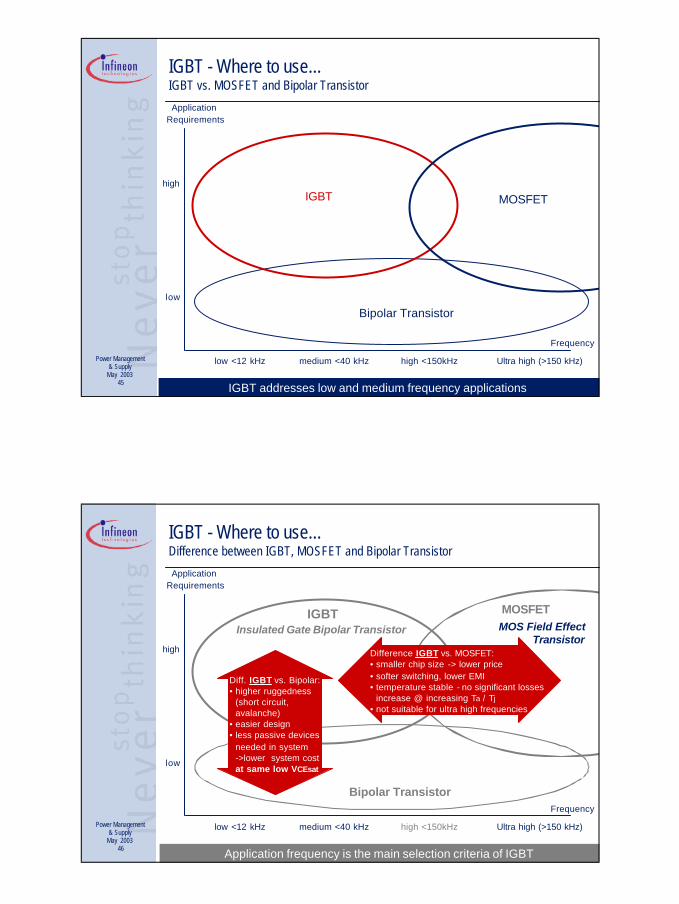
Application frequency is the main selection criteria of IGBT
IGBT - Where to use...Difference between IGBT, MOSFET and Bipolar Transistor
MOS Field Effect Transistor
Difference IGBT vs. MOSFET:• smaller chip size -> lower price• softer switching, lower EMI• temperature stable - no significant losses
increase @ increasing Ta / Tj• not suitable for ultra high frequencies
Diff. IGBT vs. Bipolar: • higher ruggedness
(short circuit, avalanche)
• easier design• less passive devices
needed in system ->lower system costat same low VCEsat

Page 24
Drive and Control seminar 2003
Power Management& Supply
May 200347
IGBT BehaviourCharacteristic difference between IGBT and MOSFET
VCEsatVDS
IC
ID
The IGBT is characterized by it‘s knee voltage.Conduction loss are in linear relation to IC
The MOSFET behaves like a resistor.Conduction loss are proportional to ID²
The IGBT has a characteristic current tail.Turn off losses are dominated by the tail current.
The IGBT is basically the preferred device for higher currents at limited pulse frequencies.
knee voltage
IGBT
MOSFET VCE
t
IC
current tail
ID
UDS
IGBT
MO
SFET
Power Management& Supply
May 200348
MOSFET and IGBTDevice Structure in On State
IGBT current is provided by electrons and holes because of the additional p doped layer
RDSonMOSFET
n -
p n+
SiO2
Al
p
D
G
S
Resistor behavior : RDSon
NPT-IGBT
n -
pn+
SiO2
Al
G
p
C
E
VCEsat
Additional p layer

Page 25
Drive and Control seminar 2003
Power Management& Supply
May 200349 If a reverse voltage can occur, a DuoPack is needed.
IGBT applied to reverse voltage (VCE<0)
n-
p n+
SiO2
Al
p
C
G
E
Diode withundefined
reversevoltage ~30V
VCE<0n+
n -
p
C
A
n-
p n+
SiO2
Al
p
C
G
E
Single IGBT
The pn- Diode has an undefined blocking voltage
-> Reverse voltage VCE<0 is not allowed.
IGBT with anti parallel Diode (DuoPack™)
Under reverse voltage condition current flow in the
anti parallel Diode occurs.
Power Management& Supply
May 200350
Benefits of NPT
Technology
1) Thinner wafer → lower thermal resistance RthJC→ less carriers in IGBT on state
and therefore reduced Eoff.
2) Positive temperature coefficientof VCEsat
→ easy paralleling capability→ high short circuit withstand time.
3) Temperature stable behavior→ turn-on and turn-off characte-
ristic dos not depend on thetemperature.
4) No Epitaxie process required→ Lower cost.
emitter
n-p
n +Al
pcollector
600V NPT-IGBT
E
x
n +
SiO2
collector
emitter
Al
p+
n-
n+ Buffer
p
600V PT-IGBT
E
x
Insulated Gate Bipolar Transistor - IGBTNPT versus PT Technology
Thin wafer technology allows NPT IGBT’s also for 600V.

Page 26
Drive and Control seminar 2003
Power Management& Supply
May 200351
TrenchStop™ IGBT and DuoPack™ 1200VTrenchStop versus Fast IGBT
1200V TrenchStop is implemented with Trench and Field Stop technologyand regards InfineonsThin Wafer Technology
1200V TrenchStop is implemented with Trench and Field Stop technologyand regards InfineonsThin Wafer Technology
Advantage for the Infineon Customer
Thinner wafer → massive reduction of
conduction losses→ Ideal IGBT for
Drives Applications
emitter
n-
p
p
n +Al
collector
1200V Fast IGBT
emitter n + Al
n-
p+
p body
collector
1200V TrenchStop
pn-Fieldstop
TrenchStop helps to save energy.
Power Management& Supply
May 200352
60 -120 µmHuman hair
<100µm
TrenchStop
600V
100µm
Fast IGBT
600V
120µm
TrenchStop
1200V
175µm
Fast IGBT
1200V
70µm
EmCon
600V
120µm
EmCon
1200V
New Technologies, starting with higher voltage IGBTsThickness of different IGBTs and Diodes
Due to the thin Chip thickness a major challenge for 600V products is the reliable manufacturing process.

Page 27
Drive and Control seminar 2003
Power Management& Supply
May 200353
Turn off behavior
Turn off Infineon SKW20N60HS - High Speed IGBT
PT-technology competitors: High tail current + Eoff
SKW20N60HS
-5
-4
-3
-2
-1
0
1
2
3
4
5
0 0.1 0.2 0.3 0.4 0.5 0.6t [µs]
V,
I
Turn off Fairchild HGTG12N60A4D - SMPS I
HGTG12N60A4D
-5
-4
-3
-2
-1
0
1
2
3
4
5
0 0.1 0.2 0.3 0.4 0.5 0.6t [µs]
V,
I
Turn off International Rectifier IRG4PC40W - Warp Speed
IRG4PC40W
-5
-4
-3
-2
-1
0
1
2
3
4
5
0 0.1 0.2 0.3 0.4 0.5 0.6t [µs]
V,
I
SKW20N60HS - HGTG12N60A4D - IRG4PC40W
-5
-4
-3
-2
-1
0
1
2
3
4
5
0 0.1 0.2 0.3 0.4 0.5 0.6t [µs]
V,
I
Uce_HS
Ic_HS
Uce_HGTG
Ic_HGTG
Uce_IRW
Ic_IRW
Infineon: Negligible tail current è Minimum Eoff at 150°C
Power Management& Supply
May 200354
0
50
100
150
200
250
300
0 50 100 150 200 250 300 350 t [ns]
VCE [V]
0
5
10
15
20
25
IC [V]
Epi-DiodeEmCon™
Epi-DiodeEmCon™
IGBT turn-on losses dependence on the Diode.
Using EmCon Diode reduces IGBT turn off losses by 40%.
EmConTM Diode 600V & 1200V for DuoPackTM
Turn on measurement

Page 28
Drive and Control seminar 2003
Power Management& Supply
May 200355
600V EmCon™Dynamic Performance
EmCon offers low Qrr=> reduced switching losses, soft behavior => EMI reduction.
(IGBT: SGP06N60, TJ = 150°C, RG = 47Ohm, DC link 300V)
-20
-10
0
10
IF [A]
0 0.05 0.1 0.15 0.2 0.25 0.3 0.35 0.4 0.45 t [µs]
EmConCompetitor 1Competitor 2
Low maximum reverse recovery current,low reverse recovery charge
Fast rise of blocking voltage, butdU/dt limited (EMC!)
Soft recovery
0
150
UF [V]
300
-150
450