ijet journal of engineering and technology...
TRANSCRIPT
International Journal of Engineering and Technology Volume 5 No. 12, December, 2015
ISSN: 2049-3444 © 2015 – IJET Publications UK. All rights reserved. 623
Performance Analysis of the WCDMA End-To-End Physical Layer
1B. O. Omijeh,2M.I.Udoh
1Department of Electronic & Computer Engineering 2Centre for Information and Telecommunications Engineering University of Port Harcourt, Nigeria
ABSTRACT
In this paper, the performance analysis of a WCDMA End-to-End Physical Layer has been achieved. The goal for the next
generation of mobile communications system is to seamlessly integrate a wide variety of communication services such as high speed
data, video and multimedia traffic as well as voice signals. The technology needed to tackle the challenges to make these services
available is popularly known as the Third Generation (3G) Cellular Systems. One of the most promising approaches to 3G is to
combine a Wideband Code Division Multiple Access (WCDMA) air interface with the fixed network of Global System for Mobile
communications (GSM). In this paper, a signal simulator was implemented according to the physical layer specification of the IMT-
2000 WCDMA system. The data is transmitted in a frame by frame basis through a time varying channel. The transmitted signal is
corrupted by Multiple access interference which is generated in a structured way rather than treating it as Additive White Gaussian
Noise (AWGN). The signal is further corrupted by AWGN and Rayleigh fading at the front end of the receiver. Simple rake diversity
combining is employed at the receiver. The bit error rate was investigated at the downlink for different channel conditions.
Performance improvement due to error correction coding scheme was observed. The simulator developed can be an invaluable tool
for investigating the design and implementation of WCDMA systems.
Keywords:3GPP,WCDMA,RAKEDIVERSITY,AWGN,GSM
1. INTRODUCTION
Wideband Code Division Multiple Access (WCDMA) is
a 3rd generation Mobile Communication System that uses
Code Division Multiple Access (CDMA) technology over a
wide frequency band to provide high-speed multimedia and
efficient voice services. The WCDMA infrastructure is
compatible with GSM mobile radio communication system.
The objective of this work, is to present the wideband CDMA
air interface scheme that is currently being developed by the
standardization organizations in Europe, Japan, the United
States, and Korea for third-generation communication
systems. And also, to develop a simulated design model that
allows the evaluation of different variables in the wireless
communication system, such as the properties of the channel,
which are affected by environmental factors in the design [1-
2
The motivation for what came to be known as WCDMA was
both increased information rate, so as to ensure the capability
of transmitting multimedia traffic, and enhanced robustness to
multipath fading, an attribute which ultimately results in
higher capacity [3-4]
The Physical Layer The physical layer offers data transport services to higher
layers. The access to these services is through the use of
transport channels via the MAC sub-layer. The physical layer
is expected to perform the following functions in order to
provide the data transport service:
Error detection on transport channels and indication
to higher layers
FEC encoding/decoding of transport channels
Multiplexing of transport channels and
demultiplexing of Coded Composite Transport
Channels (CCTrCHs)
Rate matching of coded transport channels to
physical channels, Mapping of coded composite
transport channels on physical channels, Power
weighting and combining of physical channels,
Modulation and spreading/demodulation and
dispreading of physical channels
Frequency and time (chip, bit, slot, frame)
synchronization.
Radio characteristics measurements including FER,
SIR, Interference Power, etc., and indication to
higher layers. - Inner - loop power control.
RF processing.
Synchronization shift control
Beam forming
Hybrid ARQ soft-combining for HS-DSCH and E-
DCH. http://www.3gpp.org
The WCDMA system uses two types of radio channels;
Frequency Division Duplex (FDD) and Time Division
Duplex (TDD). The FDD radio channels are primarily used
for Wide Area Voice (audio) channels and data services. The
TDD channels are typically used for systems that do not have
the availability of dual frequency bands. In this duplex
method, uplink and downlink transmissions are carried over
the same frequency band by using synchronized time
intervals. Thus time slots in a physical channel are divided
into transmission and reception part, [5-6]
There are two main types of Wideband CDMA schemes:
network asynchronous and network synchronous. In network
asynchronous schemes the base stations are not synchronized,

International Journal of Engineering and Technology (IJET) – Volume 5 No. 12, December, 2015
ISSN: 2049-3444 © 2015 – IJET Publications UK. All rights reserved. 624
while in network synchronous schemes the base stations are
synchronized to each other within a few Micro- second. [7-8]
WCDMA Key Features [5]:
The key operational features of the WCDMA radio interface
are listed below.
Support of high data rate transmission: 384 kbps
with wide area coverage, 2 Mbps with local
coverage.
High service flexibility: support of multiple parallel
variable rate services on each connection
Both Frequency Division Duplex (FDD) and Time
Division Duplex (TDD)
Built in support for future capacity and coverage
enhancing technologies like adaptive antennas,
advanced receiver structures and transmitter
diversity.
Support of inter frequency hand over and hand over
to other systems, including hand over to GSM.
Efficient packet access.
Performance Enhancing Schemes
A number of performance enhancing schemes has been
proposed for the WCDMA systems. They include adaptive
receiving antennas, transmit diversity schemes, and advanced
receiver structures.
Adaptive Antennas: Adaptive antennas at the receiver can
increase the capacity and coverage of the system. Connection
dedicated pilot bits can be used in both the links for
employing adaptive antennas.
Transmit Diversity Schemes: Transmit diversity schemes at
the downlink employ multiple transmit antennas at the base
station. They provide performance enhancement similar to
that with multiple antennas at the mobile station receivers.
These schemes are attractive since they transfer the
processing burden to the base station. The transmit
diversity schemes proposed for the WCDMA systems fall
broadly into two different categories:
Open Loop
Closed Loop
2. REVIEW OF RELATED WORK
[5] showed that the 5MHz channel capacity of the W-CDMA
is 82. This is 3.4 times the capacity of current analog cellular
systems (AMPS).In this paper, a comprehensive review of the
wideband CDMA scheme is provided, focusing on key
technical features of the system.
2G systems were primarily designed to support low data rate
digital voice and short messaging with relatively low quality
of service. Therefore, the baseband algorithms had lower
complexity, lower sampling rates, and lower performance
requirements. However, 3G systems was introduced to
support real-time voice applications at toll quality and support
real-time multimedia and high data rate of internet and
mobile data applications with qualities comparable to high-
speed wire-line systems such as digital subscriber loop
(DSL). Hence, the simulation of
3G systems is significantly more challenging than that of 2G.
3G systems are expected to be more power efficient and
smaller in size [9]
Souhaibe Barkat in his work described the Narrowband SIC
scheme , here the interfering signals are cancelled in the
narrowband domain. After the signals are grouped and
regenerated (as they would be in a wideband SIC scheme),
they are de-correlated by a cross-correlation matrix. The
cross-correlation matrix contains the autocorrelation and
cross-correlation coefficients between the different spreading
codes. Canceling the signals removes the interference due to
correlation with other spreading codes. Evaluating the cross-
correlation matrix is a computationally intensive task. A new
matrix must be calculated and inverted every time the user
profile changes or multipath tap changes. Therefore, the W-
CDMA specification uses a 245 chips short code (called very
long Kasami code). With short spreading code, this
implementation is more feasible. [10]
Zeba Khan Rafi (2015) showed that the bit error rate
performance of UWB systems is degraded as energy is spread
out by multipath fading. In the case of DS-UWB systems,
since the spreading factor is relatively small for high data
rates as compared with that of traditional DSSS systems, they
are highly exposed to inter pulse interference (IPI) and energy
spread. There is therefore a need to compensate the multipath
fading effects and the use of a RAKE receiver is the solution.
Remco Van Der Hofstad(2004) in the First generation (1G) of
mobile communication systems, each user is assigned a
frequency, like radio. By the increase of the number of cell
phones, this system is no longer possible. In the second
generation (2G), which is often called GSM, different users
send and receive on the same frequency, and the signals are
separated by assigning each user a time window in which he
or she can transmit. This system is not very efficient, since it
is hard to adapt to changing numbers of users. Therefore, the
allowed time and frequency window is not used optimally. In
the third generation systems, users are distinguished by their
coding sequences, which gives a flexible system, in which the
amount of bandwidth is used more effciently.
3. SYSTEM ANALYSIS AND DESIGN

International Journal of Engineering and Technology (IJET) – Volume 5 No. 12, December, 2015
ISSN: 2049-3444 © 2015 – IJET Publications UK. All rights reserved. 625
This section describes the simulator designed to evaluate the
Bit Error Rate (BER) at the downlink of a Wideband CDMA
(WCDMA) system. Data is transmitted in a frame by frame
basis over a time varying multipath channel. Receiver design
incorporates rake diversity combining. Additive White
Gaussian Noise (AWGN) + Rayleigh fading is added at the
front end of the rake receiver. Multiple Access Interference
(MAI) is generated in a structured way rather than treating it
as
AWGN. The flowchart in Fig.1 illustrates the file structure of
the uplink and downlink simulators:
Data generation, channel and chip-matched filtering can be
modeled in a WCDMA system with K users and a spreading
code with N chips per bit. Bi-phase Shift Keying (BPSK)
modulation can be used with each transmitted signal limited
to [0: T]. The kth user's transmitted signal S k (t) is given by:
3.1 Modeling of Data, Channel and Chip-Matched Filtering
L-1
S k (t) = √ (2Pk) ∑ b k, I x ck (t – i T) (1)
i=0
where, P k = transmitted power of kth user; b k , i
Є {+1, -1} is the I t h transmitted bit in a stream of L bit

International Journal of Engineering and Technology (IJET) – Volume 5 No. 12, December, 2015
ISSN: 2049-3444 © 2015 – IJET Publications UK. All rights reserved. 626
UP DOWN
UP_SIMM.M DOWN_SIMM.M
Fig.1 Simulator Code Structure
N-1
C k (t) = ∑ C k, n π (t - nTc) (2)
n=0
It should be noted that the transmitted signal Sk(t)
corresponds to y t x in the Matlab simulation programs.
Equation (2) is a spreading waveform with C k,n Є {+1, -1}
and π (t) being a rectangular pulse of duration Tc ; T=nTc as
there are N chips per bit. The received signal due to the
superposition of the attenuated and delayed signals of the K
users is given by:
WCDMA. M
MAIN MENU. M
UPLINK .M
UPMENU. M
DOWNMENU. M
DOWNLINK .M
UPLINK OR
DOWNLINK?
International Journal of Engineering and Technology (IJET) – Volume 5 No. 12, December, 2015
ISSN: 2049-3444 © 2015 – IJET Publications UK. All rights reserved. 627
k
r(t) = ∑ wk x Sk(t – ζ k ) + v(t) (3)
k=1
where Wk is the complex amplitude with which the kth signal
is received and includes the effect of channel attenuation and
the phase offset; ζk is the relative delay with respect to a
reference at the receiver. This received signal at the channel
output r(t) corresponds to y noisy in the Matlab simulation
programs. The noise component v (t) is assumed to be
Gaussian with zero-mean and double-sided spectral density of
N0/2. This received signal is fed into a chip matched filter
whose output is as follows:
(n+1)Tc
r(n) = ∫ r(t) dt (4)
nTc
A discrete observation vector ř i is formed at bit i by sampling
the integrator output and collecting N successive chip-
matched filter outputs given by:
ři = [ř[i], ř[i + 1], . . . , ř [i + N-1]]T (5)
Each observation vector ři can be viewed as a linear
combination of 2K signal vectors, corresponding to 2 from
each of the K users due to the past and the current bits. So ři
can be written as:
ři = AWbi + vi (6)
with vi ≈ N(0, k), where A is the N x 2K matrix signal
vectors, which depends on spreading codes of each user; W is
the 2K x 2K diagonal matrix of complex amplitudes; bi is the
2K x 1 vector of K users’ previous and current data bits; and
the N x 1 vector K, is the noise covariance. The matrices A,
W and bi are expanded below.
A (ζ) ≡ [a1R (ζ1) a1
X (ζ1), .., akR (ζk) ak
X (ζk)] (7)
Let a kR (ζk) = (1 - yk ) ck
R [qk] + yk ckR [qk+ 1] (8)
and akX(ζk) = (1 - yk)ck
X [qk] + ykckX[qk+ 1] (9)
The N x 2K matrix A(ζ) has a column corresponding to two
adjacent bits of each user given that qk Є {0, 1, ……, N – 1}
and yk Є {0, 1}, where c kR [qk] and c k
X [qk] are the spreading
codes shifted by integer in multiples of chips delays and ζk is
the relative delay with respect to a reference at the receiver.
CkR [qk] = [ck, N-qk . .ck, N-1 0 …0]T (10)
CkX [qk] = [0 . . 0 ck,0 . . ck, qk-1 ]T (11)
Expanding A(ζ) in equation (7) by substituting equations (8)
and (9) yields:
A(ζ)={(1-y1)c1R[q1]+y1ck
R[q1+1]}
{(1-y1)c1X[q1]+y1ck
X[q1+1]},..
{(1-yk)ckR[qk]+ykck
R[qk+1]}
{(1-yk)c1X[qk]+ykck
X[qk+1]} (12)
where yi =STři is the code-matched filter detector output
vector. Equation (12) is an expression of N x 2K matrix of
relative time delays encountered by multiple signals in a
channel with respect to the receiver during transmission and
reception. When signals are transmitted, they undergo varied
delays ζk in the channel due to multipath fading effects. They
arrive at the receiver input at different instants.
Similarly,
W=diag [w1,..., wk]= w1 0 … … 0 0
0 w1 ... … 0 0
0 0 ... … 0 0
: : : : : :
: : : : : :
0 0 … … wk 0
0 0 … … 0 wk
Therefore, bi = [b1 ,i-1, b1,i, . . , b k, i] T (13)
Where b k, i is the ith bit of the kth user.
The chip matched filter block generates an output for every
chip waveform, which is then vectored and fed into the
channel estimation block. Maximum likelihood (ML) channel
estimation uses a fixed preamble which is known at the
receiver. The preamble bits are sent across the channel in the
initial part of a transmission. The ML channel estimation
block uses the resulting output from the channel in the form
of the chip matched filter vector and the knowledge of the
preamble bits is used to estimate the channel parameters
(amplitude, and delay information). The multi-user detector
uses the chip matched filter outputs and the matrix which
conveys the delay and amplitude information to detect the
bits of all the users

International Journal of Engineering and Technology (IJET) – Volume 5 No. 12, December, 2015
ISSN: 2049-3444 © 2015 – IJET Publications UK. All rights reserved. 628
3.2 Simulated Model using Simulink
Simulink, developed by Math Works, is a graphical
programming environment for modeling, simulating and
analyzing multidomain dynamic systems. Its primary
interface is a graphical block diagramming tool and a
customizable set of block libraries.
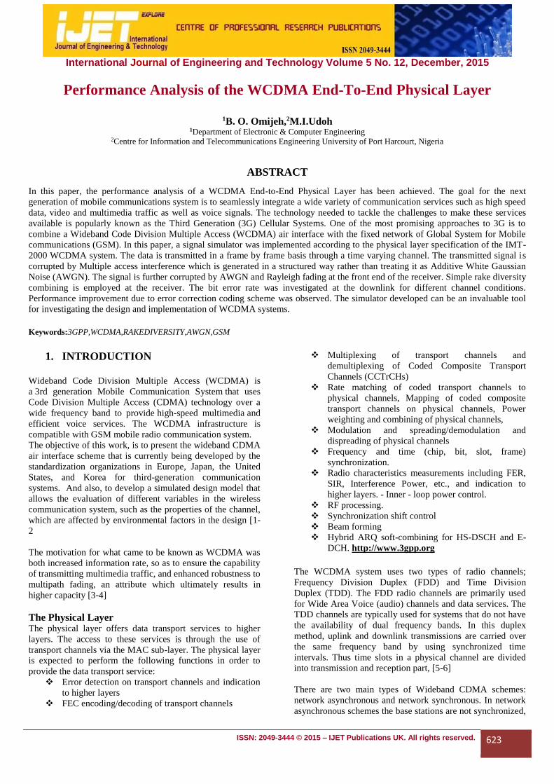
Fig.2 below is the simulated WCDMA model with AWGN
channel of the End-to- End Physical layer. It further computes
the delay between the transmitted and received signals in the
model.Fig.3 is the simulated WCDMA MODEL with
AWGN+MULTIPATH FADING channel, further more it
analyzes the effect of delay on the model by introducing the
unit delay block before modulation, after modulation, before
demodulation and after demodulation.
Fig.2 The WCDMA- AWGN Channel Model For The Downlink Physical Laye
International Journal of Engineering and Technology (IJET) – Volume 5 No. 12, December, 2015
ISSN: 2049-3444 © 2015 – IJET Publications UK. All rights reserved. 629
Fig.3 WCDMA AWGN+Multipath Channel for the End-To-End Downlink Physical Layer
Functions of Subsystems a. WCDMA DL Tx Channel Coding Scheme: The WCDMA
DL Tx Channel Coding Scheme subsystem processes each
transport channel independently according to the transport
format parameters associated with it. The different transport
channels are then combined to generate a coded combined
transport channel (CCTrCH). The CCTrCH is then sent to the
WCDMA Tx Physical Mapping subsystem.
b. WCDMA Tx Physical Mapping: This subsystem
implements the following functions:
• Physical channel segmentation
• Second interleaver
• Slot builder
The output of this subsystem constitutes a dedicated physical
channel (DPCH), which is passed to the WCDMA BS Tx
Antenna Spreading and Modulation subsystem.
c. WCDMA BS Tx Antenna Spreading and Modulation: The
WCDMA BS Tx Antenna Spreading and Modulation
subsystem performs the following functions:
• Modulation
• Spreading by a real-valued orthogonal variable
spreading factor (OVSF) code
• Scrambling by a complex-valued Gold code
sequence
• Power weighting & Pulse shaping
d. WCDMA Channel Model: The WCDMA Channel Model
subsystem simulates a wireless link channel containing
additive white Gaussian noise (AWGN) and, if selected, a set
of multipath propagation conditions.
e. WCDMA UE Rx Antenna: The received signal at the
WCDMA UE Rx Antenna subsystem is the sum of attenuated
and delayed versions of the transmitted signals due to the so-
called multipath propagation introduced by the channel. At
the receiver side, a Rake receiver is implemented to resolve
and compensate for such effect. A Rake receiver consists of
several rake fingers, each associated with a different received
component. Each rake finger is made of chip correlators to
perform the despreading, channel estimation to gauge the
channel, and a derotator that, using the knowledge provided
by the channel estimator, corrects the phase of the data
symbol. The subsystem coherently combines the output of the
different rake fingers to recover the energy across the
different delays.
f. WCDMA Rx Physical Channel Demapping and Channel
Decoding Scheme: The WCDMA Rx Physical Channel
Demapping and the WCDMA DL Rx Channel Decoding
Scheme subsystem decode the signal by performing the
inverse of the functions of the WCDMA DL Tx Channel
Coding Scheme subsystem.

International Journal of Engineering and Technology (IJET) – Volume 5 No. 12, December, 2015
ISSN: 2049-3444 © 2015 – IJET Publications UK. All rights reserved. 630
4. RESULTS AND DISCUSSION
This section contains the results obtained after series of test
carried out, experimentation and simulations.
Findings and Discussion
The Subsystem coherently combines the output of the
different rake fingers to recover the energy across
the different delays.
WCDMA systems use Interference suppression
at the receiver and multiple antennas at the
transmitter.
Orthogonality among channels is preserved
better at the downlink.
When a signal is received over a multipath
fading channel, the amplitude distribution of the
spread spectrum becomes more and more specular as
the spread bandwidth increases. This is
irrespective of the fading statistics of the received
waveform.
The effect of any residual measurement
inaccuracy is less in a wideband system than
it is in a narrow band system, that is for a given
power control error ,the decrease in capacity
experienced by a narrowband CDMA is greater than
that seen by a WCDMA system.
Pilot bits assists coherent demodulation and
channel estimation
With WCDMA, a user's information bits are spread
over an artificially broadened
bandwidth. The job is done by multiplying them
with a pseudorandom bit stream running several
times as fast. It increases the bit-rate of the signal
(and the amount of bandwidth it occupies) by a ratio
known as the spreading factor, namely, the ratio of
the chip rate to the original information rate. The
scheme can also resolve different propagation paths,
turning multipath distortion from a destructive
nuisance into a helpful ally.
At the receiver output, the amplitude of the de-
spread signal is increased by the spreading factor
relative to interfering signals. In the process, those
interfering signals are diminished and simply add to
the background noise level. In other words,
correlation detection uses the spreading factor to
raise the desired user signal from the interference.
The effect is called processing gain.
Table 1 BLER, BER, AND SAMPLE Rate Computation Associated With Each Transport Channel
From Table 1, it is observed that, increasing the Simulation
time at progressive intervals and constant sample rate has no
effect on the bit error rate results, hence the WCDMA system
can be said to be less prone to errorr
SAMPLE
RATE
SIMULATION
TIME
BLER CALCULATION ERROR RATE CALCULATION ERROR RATE CALCULATION
BLER CALCULATION
BLOCKS BLER ERROR COUNT
SAMPLES BLER ERROR COUNT
SAMPLES
0.001 0.1 0 5 0 0 976 0 0 100
0.001 0.2 0 13 0 0 2196 0 0 400
0.001 0.3 0 20 0 0 3416 0 0 600
0.001 0.4 0 28 0 0 4636 0 0 900
0.001 0.5 0 35 0 0 5856 0 0 1100
0.001 0.6 0 43 0 0 7076 0 0 1400
0.001 0.7 0 50 0 0 8296 0 0 1600
0.001 0.8 0 58 0 0 9516 0 0 1900
0.001 0.9 0 65 0 0 1.07E+04 0 0 2100
0.001 1 0 73 0 0 1.20E+04 0 0 2400
International Journal of Engineering and Technology (IJET) – Volume 5 No. 12, December, 2015
ISSN: 2049-3444 © 2015 – IJET Publications UK. All rights reserved. 631
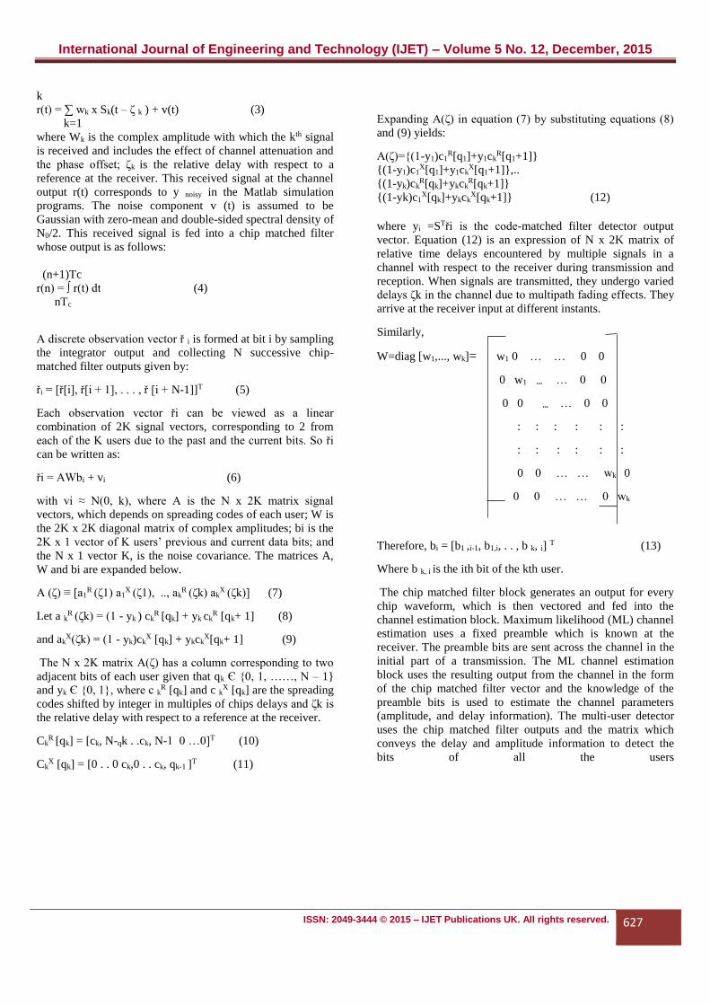
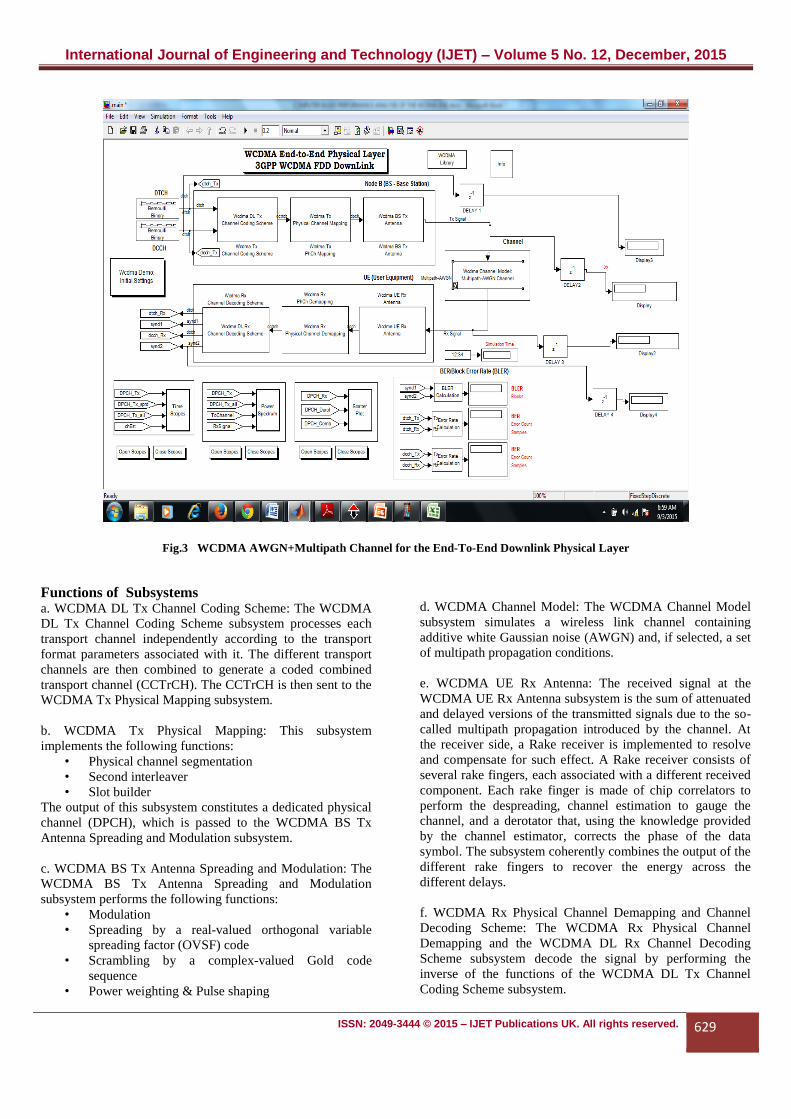
Table 2: Effects of Unit Delay in the WCDMA End- To -End Downlink Physical Layer
SAMPLE
RATE
SIMULATION
TIME
EFFECT OF
DELAY BEFORE
MODULATION
EFFECT OF
DELAY AFTER
MODULATION
EFFECT OF DELAY
BEFORE
DEMODULATION
EFFECT OF DELAY AFTER
DEMODULATION
0
0.001 0.1 0 0.2458-1.046i -1.589+1.257i 0
0.001 0.2 0 0.09683-0.07827i -3.034+0.9746i 0
0.001 0.3 1 -0.4157+0.6866i -2.554+1.232i 0
0.001 0.4 0 -0.5775-1.489i -2.718-2.944i 0
0.001 0.5 1 1.914+0.01616i 6.211+2.297i 0
0.001 0.6 0 0.05651-0.8623i -0.1342+3.655i 0
0.001 0.7 0 -0.1341 -0.414 0
0.001 0.8 1 0.706 3.49 0
0.001 0.9 0 0.334 0.4141 0
0.001 1 0 0.7356 -3.12 0
From Table 2, the following deduced:
Introducing the unit delay block before and after modulation
has an impact on the system as can be seen from the values
obtained.
Introducing the unit delay block before demodulation also has
an impact on the system, however after demodulation the
effect of delay on the system is subdued.
Fig.4: Effect of Delay before Modulation Fig.5: Effect of Delay after Modulation
Fig 4: Effects of Delay before Modulation
FINDINGS AND DISCUSSIONS
Fig 6: Effect of Delay before Demodulation
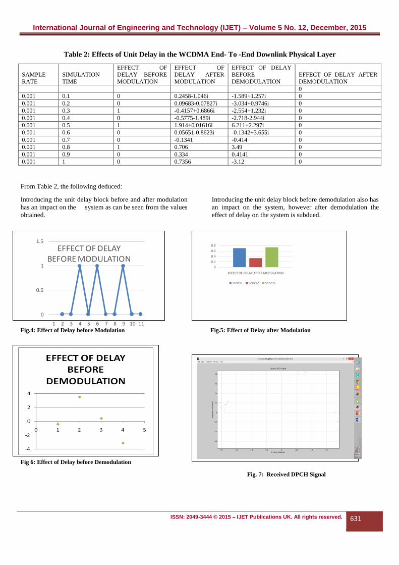
Fig. 7: Received DPCH Signal
0
0.5
1
1.5
1 2 3 4 5 6 7 8 9 10 11
EFFECT OF DELAY BEFORE MODULATION
0
0.2
0.4
0.6
0.8
EFFECT OF DELAY AFTER MODULATION
Series1 Series2 Series3

International Journal of Engineering and Technology (IJET) – Volume 5 No. 12, December, 2015
ISSN: 2049-3444 © 2015 – IJET Publications UK. All rights reserved. 632
Fig 4- 6, show the effect of delays before and after modulation and demodulations respectively
.Fig.7 shows that there were more Distortion and delay
interval due to Multipath fading
Fig.8: Rake Combined DPCH Fig.9: Derotated DPCH Signal
Fig. 8 shows less distortion and delay interval due to rake
receiver. Fig 9 Receiver compensates for the attenuation
caused by the channel by correcting the phase of the data
symbol
.
Fig.10: Before Spreading Spectrum Fig.11: Before Pulse Shaping Spectrum
Fig.10: Before Spreading Spectrum: Output characterized by a Rayleigh probability distribution

International Journal of Engineering and Technology (IJET) – Volume 5 No. 12, December, 2015
ISSN: 2049-3444 © 2015 – IJET Publications UK. All rights reserved. 633
Fig.12: Power Spectrum/ Tx Signal by the WCDMA BS
Tx Antenna
Fig.13: Power Spectrum/Rx Signal by the WCDMA UE Rx
Antenna
Fig.14: Real part: Data is spread by a real-value orthogonal
signal code for channel separation
Fig.15: Imaginary Part: Data is scrambled by a complex-valued
Gold code sequence

International Journal of Engineering and Technology (IJET) – Volume 5 No. 12, December, 2015
ISSN: 2049-3444 © 2015 – IJET Publications UK. All rights reserved. 634
5. Conclusion
The simulation of Wireless Communication System allows
the evaluation of different variables in the system, such as the
properties of the channel, which are affected by
environmental factors in the design. One of the most
challenging parts of the design of wireless Cellular
communication systems is the design of the baseband
physical layer. The baseband physical layer algorithms are
designed to establish and maintain a reliable radio link
between base stations and user terminals. These baseband
algorithms are designed to overcome propagation effects,
interference effects, and degradation effects resulting from
nonlinearities and noise in the hardware implementation.
The development of the WCDMA wireless communication
system physical layer link, which was carried out
successfully, can be used as a simulation Model for the
design and development of WCDMA wireless cellular
communication system. Comparing the performances of
narrowband CDMA and WCDMA methods of simulations, it
was shown that the later was more efficient than the former.
This shows that WCDMA is much better for the design and
implementation of 3G wireless communication systems than
the narrowband CDMA.
REFERENCES
[1] Omijeh, B.O and Biebuma.J.J (2009): “Voice
capacity enhancement for CDMA 2000 Network”,
International Journal of Engineering Research and
Development, Vol. 8, No. 3, pp 29-36.
[2] Martin Sauter: Communication Systems for the
Mobile Information Society, John Wiley, September
2006, ISBN 0-470-02676-6
[3] Esmael H.Dinan and Bijan Jabbari, (1998):
“Spreading Codes for Direct Sequence CDMA
and Wideband CDMA Cellular Networks”, IEEE
Communications Magazine, vol. 36, no. 9, pp. 48-
54
[4] Ojanperä, T., Prasad, R. and Harada, H.,
(1998):”Qualitative Comparison of Some Multiuser
Detector Algorithms for Wideband CDMA",
Proceedings of VTC'98 (the IEEE Vehicular
Technology Conference for 1998), Ottawa, Canada,
pp. 46-50.
[5] Fumiyuki Adachi, Mamoru Sawahashi and Hirohito
Suda, (1998): “Wideband DS-CDMA for Next
Generation Mobile Communications Systems”,
IEEE Communications Magazine, vol. 36, no. 9, pp.
55-69.
[6] Omijeh, B.O, R. Okinege, R.Ochi (2013): “Traffic
Modelling for capacity analysis of CDMA
Networks using Gaussian, International Journal of
Electronic , Communication and Computer
Engineering (IJECCE), Vol 5, N0. 3, 2013
Fig.16: Channel Estimates:
Efficient Channel Estimates of pilot bits
Fig.17: Bandlimited Impulse Response
International Journal of Engineering and Technology (IJET) – Volume 5 No. 12, December, 2015
ISSN: 2049-3444 © 2015 – IJET Publications UK. All rights reserved. 635
[7] Michael H. Callendar,(1997): “International Mobile
Telecommunications-2000Standard Efforts of the
ITU”, IEEE Personal Communications, vol. 4, no. 4,
pp.6-7
[8] Omijeh, B.O and Agoye, S.D.O (2015): Simulation
And Evaluation Of Ofdm Based Digital Video
Broadcasting (Dvb) Over Different Wireless
Communication Channels ,International Journal Of
Scientific & Engineering Research, Volume 6, Issue
10, Pp: 738-745
[9] Malcolm W. Oliphant's, (1999): "The mobile phone
meets the Internet", IEEE Spectrum, Vol. 8, pp. 20-
28.
[10] Ahonen and Barrett (editors), Services for UMTS
(Wiley, 2002) first book on the services for 3G,
ISBN 978-0-471-48550-6
[11] Holma and Toskala (editors), WCDMA for UMTS,
(Wiley, 2000) first book dedicated to 3G technology,
ISBN 978-0-471-72051-5