ijet simulation of ultra high bit rate dwdm/pdm/sdm...
TRANSCRIPT

International Journal of Engineering and Technology Volume 6 No.12, December, 2016
ISSN: 2049-3444 © 2016 – IJET Publications UK. All rights reserved. 443
Simulation of Ultra High Bit Rate DWDM/PDM/SDM System Using FMF
Supporting 20 Spatial and Polarization Modes Enabling Multi-Mode Splicers
with QPSK Modulation Format
Ibraheem Abdullah Murdas and Musaddak Maher Abdul Zahra
Department of Electrical Engineering, University of Babylon – Hillah – Iraq.
ABSTRACT
Optical fiber communication is the backbone for the telecommunications infrastructure that supports the internet. Single-mode fiber
transmission can no longer satisfy exponentially growing capacity demand. It is well known that the capacity of a communication
channel cannot exceed the Shannon limit. This paper demonstrates simulation framework for few-mode fiber based space division
multiplexing (SDM) transmission system. The technique has been proposed as an option for further capacity increase of transmission
fibers. Polarization dual multiplexing (PDM) and dense wavelength multiplexing (DWDM) techniques are also used in this system to
increase total system data rate. An extra dimension that a fiber can offer for achieving more information is space. For the ultra-high
capacity need of SDM, we have proposed the FMF as SDM highest technology for obtaining ultra-high bit rate systems. The
challenge is the inter-core crosstalk of the high-order modes. The properties of modes were investigated using the uncoupled-mode
theory. In this paper, we explore the design and modeling of DWDM technique with sixteen channels over ten cores SDM/PDM
system proposed as future of ultra-high capacity optical system. The approach of adaptive multi-input multi-output (MIMO) digital
signal processing (DSP) has been proposed and demonstrated to untangle the crosstalk between the spatial modes and compensate
the DMGD. Different sub-channels are synchronously sampled, and the sampled signals from adjacent sub-channels are processed
jointly using DSP in a form of float matrix to remove different fiber impairments.
Keywords: SDM, FMF, FM-EDFA, QPSK, MIMO
1. INTRODUCTION
Since its conception and implementation; optical fiber
communication has become the backbone for the
telecommunications infrastructure that supports the internet
and various other high-volume data applications; nearly every
call we make, every text message we send, every movie we
download and every internet based application is then
converted into a ray of photons that travels through the
billions of kilometers of optical fiber that’s been deployed
around the globe [1]. In order to respond to these growing and
urgent demands for bit rates, research in optical-fiber
communications introduced a number of innovative solutions
that led to the development of high bitrate optical
transmission systems [2]. To satisfy the ever-increasing
capacity demand in optical fiber communications, both the
spectral efficiency (SE) and the data rate carried by a
wavelength channel have been increasing dramatically [3].
Space-division multiplexing (SDM) is being considered as a
promising candidate technology to dramatically increase per-
fiber capacity [4]. Per-fiber capacities of over 100 Tb/s have
been recently demonstrated by using SDM with multi-core
fibers (MCFs) [5], surpassing with ease the highest capacity
reported over single-mode fiber [6].
Space-division multiplexing (SDM) has emerged as a next-
generation technology to sustain the continuous traffic growth,
in order to keep up with the future of Internet bandwidth
requirement [7].Among SDM technologies, SDM using few-
mode fiber (FMF) transmission has been extensively explored
[8-9]. Since the conventional multi-mode fiber (MMF) is not
suitable for long distance SDM transmission because of its
very large differential mode group delay (DMGD) and more
than hundreds of spatial modes, the few-mode fiber is
developed with only the support of small number of spatial
modes at relatively small DMGD [10]. Figure (1) shows the
evolution of transmission capacity in optical fibers as
evidenced by state of the art laboratory transmission
demonstrations over the years.

International Journal of Engineering and Technology (IJET) – Volume 6 No. 12, December, 2016
ISSN: 2049-3444 © 2016 – IJET Publications UK. All rights reserved. 444
Fig. 1: The evolution of transmission capacity in optical fibers
i. Architecture of SDM system
The concept of SDM was demonstrated to transmit signals
over multiple fiber cores as early as 1970, but the crosstalk
between any two cores cannot be finely controlled. Until
recently, as the predicted capacity crunch of single-mode
fiber for rapidly growing traffic, SDM technology is re-
considered as the promising way to sustain the bandwidth
requirement in future decades. On one side, the manufactural
progress of optical components, like specialized design of
large DMGD or low crosstalk MMF, fine fabrication control
of multicore or hollow-core fiber, and specialized mode
generator and so on [11].
As shown in Figure 2, N optical channels are spatially
multiplexed with mode multiplexer (MUX) and transmitted
through SDM fibers. After fiber transmission, the mode de-
multiplexed (DEMUX) is used to separate the N spatial
channels. Since most of MUX and DEMUX are still free
space devices, they can induce significant power loss and
mode coupling. There have been proposed different types of
SDM fibers including bundled SMF, FMF, and MCF. The
inter-modal crosstalk and link modal dispersion varies by the
fiber type.
Fig.2: Architecture of SDM systems
Table 1 comprehensively compared three fiber or cable types
for SDM transmission: bundled SMF, MCF, and FMF.
Because the MMF needs to support numerous spatial modes,
which requires larger fiber numerical aperture, it may have
very low loss in fusion splicing, which can save more link
budget on SDM transmission. Because all spatial modes share
the same transmission media, there is inevitable inter-modal
crosstalk between any two spatial or polarization modes.

International Journal of Engineering and Technology (IJET) – Volume 6 No. 12, December, 2016
ISSN: 2049-3444 © 2016 – IJET Publications UK. All rights reserved. 445
Table 1: Comparison of different SDM technologies
Parameter Bundled SMF MCF FMF
Fiber loss Standard As low as SMF As low as
SMF
Intra-mode
nonlinearity
Standard Standard or
high
Low
Inter-mode
nonlinearity
No Low Low to
medium
Mode
coupling
crosstalk
No Medium Low to high,
can be
optimized
No. of
amplifiers
N N 1
Fusion
splicing
Easy Special splicer,
Probably high
loss
Easy, low
loss
No. of
ROADM
N N 1
DSP
complexity
Low Low to
medium
Medium to
high
Application Interconnect &
long
reach
Interconnect &
long
reach
Long reach
ii. FMF system modal
Fig. 3: Supported LP-Modes for given values of the
normalized frequency and normalized propagation constant
A few-mode fiber is similar to a multi-mode fiber but with
reduced number of modes so that each mode can be handled
with care. The fiber mode concept is presented in the
following as preliminary knowledge for the discussion
afterwards. In MDM, it has been explored other modes other
than the fundamental mode that can be supported in optical
fibers. Figure (3) shows the supported modes given the
normalized frequency and the normalized propagation
constant.
The propagation constant β of each mode can be found by
numerically solving the eigenvalue equation derived from
Maxwell’s equations for a cylindrical dielectric waveguide
[14]. The definition of β is:
…………………………
……………………………
………………………………………………………1
where 𝜆 is the wavelength in vacuum and is the
effective index of each mode. An important parameter for
optical fiber is the V number, also called the normalized
frequency, represented as [14]:

International Journal of Engineering and Technology (IJET) – Volume 6 No. 12, December, 2016
ISSN: 2049-3444 © 2016 – IJET Publications UK. All rights reserved. 446
……………
………………..2
where d is the diameter of fiber core, a is the radius of the
fiber, and and are the refractive indices of the core
and cladding, respectively.
Figure 4 shows the effective index of lower order
vector modes as a function of d (bottom axis) and V number
(top horizontal axis) in a step-index (SI) fiber with
and . As shown in Figure 4,
some vector modes have similar , due to the small
index difference defined by:
Fig. 4: The effective index of lower order vector modes as a
function of d (bottom axis) and V number (top axis) in an SI
fiber
in the so-called weakly guiding case. Therefore, linearly
polarized (LP) modes, which are called scalar modes, are
usually used to represent fiber modes as an approximation of
the vector modes.
This fiber will always support the fundamental mode, the
mode, characterized by its propagation constant and the
normalized mode profile such that the power
contained in the mode
is
……………………………………………..3.
When the fiber diameter is increase to a point where the V
number, of the fiber is greater than 2.405, the fiber can guide
light in the next higher order mode, the mode,
characterized by its propagation constant and the
normalized mode profile .
The mode has a two-fold degeneracy, rotated by
illustrated in Figure 5. Fibers guide light using a high-
index core and low-index cladding, which can be intuitively
understood as by means of total internal reflection at the core-
cladding boundary.
In step-index fiber, the refractive index is uniformly
distributed across the core surrounded by a cladding with
refractive index . The propagation constant β of any guide
mode is thus bounded by where is the
propagation constant of light in vacuum.
Under the weakly-guided approximation, the vectorial modes
of the fiber can be simplified using linearly polarization (LP)
modes whose transverse field in the core is of the form:
…………
……………………………………………………….4

International Journal of Engineering and Technology (IJET) – Volume 6 No. 12, December, 2016
ISSN: 2049-3444 © 2016 – IJET Publications UK. All rights reserved. 447
Where is the radius of the core a,
and p is a non-negative integer
referred to as the azimuthal mode number. For the same p
value, can take on discrete values, labeled by a non-
negative integer q corresponding to the number of zero
crossings of the field along radial direction.
The LP modes can be labeled as , each having two-
fold degeneracies in polarizations in x and y, and for p≠0 two
fold degeneracies in spatial orientations separated by a
rotation of π/p.
The total number of modes of the step index core fiber is
approximately [1][14][15]:
M≈ ……………………………………………………
……………………………………………………………....5
By definition, modes supported by the fiber are
orthonormal, i.e. [26],
………………
……………………………………………………………….6
which is the basis for mode-division multiplexing:
transmitting and receiving independent information
simultaneously in each fiber mode.The reason that the
orthogonality of modes can only be maintained in practical
application for a very short distance is because of crosstalk
among modes due to fiber imperfections, bending and
twisting as shown in Fig. 6 [16].
Fig. 6: Schematic of (a) an ideal two-mode fiber in which the two
parallel lines represent two orthogonal modes and (b) a real
fiber that has distributed cross talk [16].
iii. System Description:
Ultra-high capacity sixteen DWDM- SDM PDM systems
with ten spatial dimensions (fiber modes) are presented in this
section. By using polarization division multiplexing
technique and 10 spatial modes for 16 channels, the total bit
rate of system become (16Ch.*10 cores*40 GHz = 6.4 THz).
The block diagram of 16 DWDM –10 modes SDM-PDM
System is shown in figure (7).
International Journal of Engineering and Technology (IJET) – Volume 6 No. 12, December, 2016
ISSN: 2049-3444 © 2016 – IJET Publications UK. All rights reserved. 448
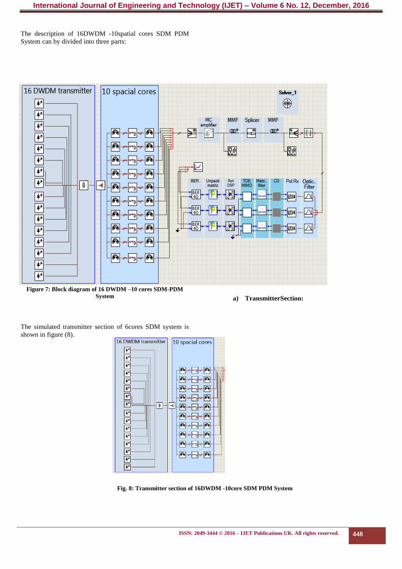
The description of 16DWDM -10spatial cores SDM PDM
System can by divided into three parts:
Figure 7: Block diagram of 16 DWDM –10 cores SDM-PDM
System
a) TransmitterSection:
The simulated transmitter section of 6cores SDM system is
shown in figure (8).
Fig. 8: Transmitter section of 16DWDM -10core SDM PDM System

International Journal of Engineering and Technology (IJET) – Volume 6 No. 12, December, 2016
ISSN: 2049-3444 © 2016 – IJET Publications UK. All rights reserved. 449
Sixteen signals produced with different emission frequencies
to be multiplexed by DWDM multiplexer. The transmission
structure of 16DWDM -10cores SDM system consists of two
parts, 16DWDM transmitter and 10spatial fiber cores. The
characterization of each part is shown below:
I. DWDM Transmitter:
The table of 16DWDM multiplexer parameters shown
below:
Table 2 DWDM multiplexer parameters description
Multiplexer
Parameter Value Units
Channel spacing 50 GHz GHz
Insertion loss 4 dB
Filter type BandPass
Filter order 3
Transfer function Gaussian
Gaussian Order 3
Frequency range 192.725 to 193.475 Thz
No. of channels 16
II. Spatial Dimensions (Fiber modes):
The output signals of power splitter distributed equally into
the ten spatial cores where array waveguides used to
demultiplex 16 combined wavelengths. The description of
AWG parameters is shown in table (3.18).
Table 3 Parameters description of AWG
AWG Mux/Demux
Parameter Value Units
Frequency spacing 50 GHz
Number of input/output ports 1/16 for Mux and 16/1 for Demux
Frequency of the first channel 192.725 THz
Frequency of the last channel 193.475 THz
Reference channel frequency 193.1e12 Hz
Passband type Gaussian
Model type Data sheet
Insertion losses 0 w
The demultiplexed optical signals modulated and dual
polarized by the same way as single channel system but an
array of 16 DP-mQAM Transmitters used in each mode. This
array modulated the incoming optical 16 signals with 40 GHz
bit rate with specified modulation techniques. . Then, the
sixteen polarization-multiplexed optical signals with
quadrature modulation multiplexed again by array
waveguide. Next, the ten spatial modes become ready to be
transmitted over few-mode fiber.
b) Optical fiber channel
In this section the propagation of 10 spatial modes into few-
mode fiber (FMF) illustrated. Multi-mode ideal coupler used
to couple 10 single-mode optical modes into a multimode
optical fiber. The supported LP modes of multi-mode coupler
and MMF are (LP01, LP11a, LP11b, LP21a, LP21b, LP02,
LP31a, LP31b, LP12a, LP12b) modes. The table of coupling
matrix is shown in table (4).

International Journal of Engineering and Technology (IJET) – Volume 6 No. 12, December, 2016
ISSN: 2049-3444 © 2016 – IJET Publications UK. All rights reserved. 450
Table 4 Parameters description of Multimode coupler for 16 DWDM 10 modes SDM PDM system
Coupling Matrix
Port Number ModeID Magnitude Phase(deg)
1 0 1 0
2 1 1 0
3 2 1 0
4 3 1 0
5 4 1 0
6 5 1 0
7 6 1 0
8 7 1 0
9 8 1 0
10 9 1 0
The FM-EDFA amplifier array model used in system as
shown in table (5).
Table 5 EDFA Parameters Description
Parameter Value Unit
Amplifier type Gain controlled
Modes gain 15 14.5 14.5 14 14.25 14.5
14.5 14.5 14.5 14.5
dBm
Modes Noise Figure 4
Noise bandwidth 2e12 Hz
NP Modes 10

International Journal of Engineering and Technology (IJET) – Volume 6 No. 12, December, 2016
ISSN: 2049-3444 © 2016 – IJET Publications UK. All rights reserved. 451
2. RESULTS AND DISCUSSION
The performance of ultra-high capacity 16DWDM 10 modes
SDM PDM system will be illustrated in this section.The
obtained results from this system are:
i. Spectrum Result:
Figure (9 shows the RF scope analyzer of 16DWDM 10
modes SDM PDM QPSK signal before and after 1550km
transmission distance at 40 Gb/s.
a
b
Figure 9: Optical OSA spectrum of 16DWDM 10cores SDM PDM QPSK signal (a) before and (b) after 1000 km transmission distance
i. Received Electrical Constellation Diagram : The received constellation diagram of the received single
channel with QPSK modulation format is presented in this
section. The following cases of constellation results will be
discussed to study the performance of system:
1.Gray mapping:
Gray codes are used in communication to minimize the
number of bit errors in quadrature phase keing
modulation adjacent points in the constellation. In a typical
encoding the horizontal and vertical adjacent constellation
points differ by a single bit and diagonal adjacent points
differ by 2 bits. The constellation diagrams for an example of
Gray code mapping for channel 1X in LP01 mode are shown
in figure (10).

International Journal of Engineering and Technology (IJET) – Volume 6 No. 12, December, 2016
ISSN: 2049-3444 © 2016 – IJET Publications UK. All rights reserved. 452
Figure 10: Received constellation diagram of channel 1X LP01 (left) Without using gray mapping ,(right) using gray mapping
The obtained results show that BER of the some received
modes channels shown in table (6).
Table 6 BER using Gray coding for 16DWDM/SDM
system
2. TDE MIMO adapter:
Equalization using multiple-input multiple-output (MIMO)
techniques is required at the receivers to mitigate linear
impairments. MIMO DSP technique is very necessary
algorithm in SDM system to compensate the inter-symbol
interference ISI caused by CD and PMD. Also MIMO used to
compensate fading and DGD losses. For example, the
obtained results using TDE MIMO equalizer for LP01 are
shown in figure (11).
Figure 11: Received constellation diagram of channel1X in LP01
mode (left) without using TDE MIMO equalizer ,(right) using
TDE MIMO equalizer.
Channel per mode
no.
Without using Gray
mapping
Using Gray mapping
1X of LP01 0.0014648 0.0009765
2X of LP11a 0.0014648 0.0012207
3X of LP11b 0.0015869 0.0010986
4X of LP21a 0.0012207 0.0007324
5X of LP21b 0.0014648 0.0010986
6X of LP02 0.0008544 0.00014648
7X of LP31a 0.0014648 0.0009765
8X of LP31b 0.0015869 0.0010986
9X of LP12a 0.0008543 0.0001456
10X of LP12b 0.0014648 0.0009765

International Journal of Engineering and Technology (IJET) – Volume 6 No. 12, December, 2016
ISSN: 2049-3444 © 2016 – IJET Publications UK. All rights reserved. 453
4. Input power:
In this section the received constellation diagrams for
1500Km transmission with different input power presented.
According to the self-phase modulation nonlinear effect
(SPM), the higher input power would lead to a larger
nonlinearity distortion. There is limitation in input power
values due to the damage threshold of optical fiber. The
threshold for stopping fiber-fuse signal propagation in
existing optical fiber is being studied in detail, but it is
currently known to be in the range of 1.2–1.4 W. Figure (12)
shows input power versus BER for 16 channels-10modes
SDM/DWDM/PDM-QPSK.
Fig. 12: Input power versus BER for 16 channels-10modes SDM/DWDM/PDM-QPSK
2. CONCLUSION
The problem of obtaining ultra-high capacity optical systems
becomes an important issue to be discussed. In this paper, we
designed powerful simulation system for space division
multiplexing. These system analysed and discussed to explain
its performance in presence of different losses. Our proposed
systems proved the principle of scaling capacity using SDM
in FMF in combination with MIMO signal processing. A total
achieved bit rate that can be obtained from our proposed
system is (6.4)THz with a total distance of 1500 Km. The
FM-EDFA has been demonstrated to be able to amplify
modes and can be used to control gain over large number of
modes and also easy to be fabricated. Although there is still a
long way to go towards real implementation, SDM
transmission has shown its great potential to be a promising
technology for the next generation optical network.
ACKNOWLEDGMENT
The authors sincerely express their gratitude to the great team
of VPI photonics for their great software VPI Transmission
maker v.9.5. Then we would like to thank the great team
working in the Babylon province electricity department for
their valuable support to achieve this work.
REFERENCES
[1] Ludwig Adolfo Tapia Martinez, A Master's Thesis,
Barcelona “Investigation on Crosstalk in Multi-core
Optical Fibers”, 2015.
[2] Elie Awwad, “Emerging Space-Time Coding Techniques
for Optical Fiber Transmission Systems”, Doctorat
ParisTech, 2015.
[3] A. R. Chraplyvy, “Plenary paper: the coming capacity
crunch,” presented at 35th European Conference on
Optical Communication, 2009. ECOC '09, Vienna,
Austria, 20-24 Sept. 2009.

International Journal of Engineering and Technology (IJET) – Volume 6 No. 12, December, 2016
ISSN: 2049-3444 © 2016 – IJET Publications UK. All rights reserved. 454
[4] M. Nakazawa, “Giant leaps in optical communication
technologies towards 2030 and beyond,” Plenary Talk
presented at 2010 36th European Conference on Optical
Communication (ECOC), Torino Italy, 19-23 Sept. 2010.
[5] J. Sakaguchi, Y. Awaji, N. Wada, A. Kanno, T.
Kawanishi, T. Hayashi, T. Taru, T. Kobayashi, and
M.Watanabe, “109-Tb/s (7x97x172-Gb/s)
SDM/WDM/PDM) QPSK transmission through 16.8-km
homogeneous multicore fiber “in Optical Fiber
Communication Conference, OSA Technical Digest (CD)
(Optical Society of America,2011), paper PDPB6.
[6] D. Qian, M.-F. Huang, E. Ip, Y.-K. Huang, Y. Shao, J.
Hu, and T. Wang, “101.7-Tb/s (370x294-Gb/s) PDM-
128QAM-OFDM transmission over 3x55-km SSMF using
pilot-based phase noise mitigation,” in Optical Fiber
Communication Conference, OSA Technical Digest (CD)
(Optical Society of America, 2011), paper PDPB5.
[7] D. J. Richardson, J. M. Fini, and L. E. Nelson, “Space-
division multiplexing in optical fibers,” Nature Photonics
7(5), 354-362 (2013).
[8] Sebastian Randel, Roland Ryf, Alberto Sierra, Peter J.
Winzer, Alan H. Gnauck, Cristian A. Bolle, René-Jean
Essiambre, David W. Peckham, Alan McCurdy, and
Robert Lingle, "6×56-Gb/s mode-division multiplexed
transmission over 33-km few-mode fiber enabled by 6×6
MIMO equalization," Opt. Express 19(17), 16697-16707
(2011).
[9] Neng Bai, Ezra Ip, Yue-Kai Huang, Eduardo Mateo, Fatih
Yaman, Ming-Jun Li, Scott Bickham, Sergey Ten, Jesús
Liñares, Carlos Montero, Vicente Moreno, Xesús Prieto
Vincent Tse, Kit Man Chung, Alan Pak Tao Lau, Hwa-
Yaw Tam, Chao Lu, Yanhua Luo, Gang-Ding Peng,
Guifang Li, and Ting Wang, "Mode division multiplexed
transmission with inline few-mode fiber amplifier," Opt.
Express 20(3), 2668-2680 (2012).
[10] L. Gruner-Nielsen, Y. Sun, J. W. Nicholson, D. Jakobsen,
R. Lingle, and B. Palsdottir, "Few Mode Transmission
Fiber with low DGD, low Mode Coupling and low Loss,"
in Optical Fiber Communication Conference, OSA
Technical Digest (Optical Society of America, 2012),
paper PDP5A.1.
[11] Xuan He, “MIMO Digital Signal Processing in Few-
Mode Fiber Optical Communication Systems”, 2014.
[12] William Shieh, An Li, Abdullah Al Amin, and Xi Chen, "
Space-Division Multiplexing for Optical
Communications", Dept. of Electrical and Electronic
Engineering, The University of Melbourne Parkville, VIC
3010 Australia, 2012.
[13] Peter J. Winzer, “Spatial Multiplexing In Fiber Optics:
The 10x Scaling Of Metro/Core Capacities", Bell Labs
Technical Journal, 2014.
[14] L. Tong, J. Lou, and E. Mazur, “Single-mode guiding
properties of subwavelength-diameter silica and silicon wire
waveguides,” Opt. Express, vol. 12, no. 6, pp. 1025–1035,
Mar. 2004.
[15] Haoshuo Chen, “Optical Devices and Subsystems for Few-
and Multi-mode Fiber based Networks”, China, 2014.
[16] Cen Xia, Master thesis, “Optical fibers for Space division
multiplexed transmission and networking”, 2015.