ijpam · 2018-04-21 · ultrasonic automatic braking system for forward and reverse collision...
TRANSCRIPT
Ultrasonic Automatic Braking System for Forward and Reverse Collision Avoidance with
Drowsiness Detection of the Driver
1. C.Jeeva2.Parag Bhargava 3.Ashwani Krishna 4.Shreya Talukdar
1 Assistant Professor, SRM Institute of Science and Technology in the Department, Electrical and Electronics, India
2, 3, 4 B-Tech, SRM Institute of Science and Technology in Electrical and Electronics, India
Abstract- In this work we have shown an intelligent Collision Avoidance System in the prototype form,
which avoids vehicle accidents and helps to detect if the driver is feeling drowsy. The Ultrasonic sensors
will continuously keep a tract of the information of the obstacles approaching the vehicle from the front
as well as the rear end. After receiving the information of any obstacle detection the Brakes are
automatically applied for saving the vehicle from collision. The system is controlled by
ATmega320PArduinoUno based microcontroller and also has an Infrared Sensor. The IR sensor works by
detecting light coming from the eye and thus helps to detect the drowsiness of the driver and helps to
automatically apply brakes avoiding havoc.
Index Terms- Collision Avoidance System, Automated Emergency Braking System, Ultrasonic Sensor, IR
Sensor, Accelerator Disengagement, Arduino Uno, drowsiness detection.
1. INTRODUCTION
The concern for automotive safety systems has been evolving over the last 30 years among the automotive industries. Every manufacturing company is taking up an initiativeto develop mechanism to safeguard people against accidents. More and more people buy vehicles every day.
Before these methods there were individual equipments such as seatbelts, airbags, knee bolsters etc. was developed to protect the driver and the passengers from injuries or death. New
preventive measures including improvement in visibility, better headlights and tail lights, windshield wipers for rains, tire traction at hilly areas, etc. have come into existence for increasing the car protection.
However, the latest surveys have shown that accidents are caused mostly due to the delay in
applying of brakes. Now we are at the stage where we have taken up the task of actively avoiding accidents as well as providing maximum protection to the vehicle passengers and as well as the people walking on the roadsides.
In this project we bring in to light an advanced idea such as proactive sensing where an
ultrasonic sensor is used at the front of the car and at the rear ends to sense any obstacle like other cars or buildings in close vicinity of the vehicle and give the signal to the microcontroller unit. According to the signal received by the Ultrasonic sensor in the vehicle’s rear and front side
ends, the microcontroller sends a signal to the braking system to apply brakes.
International Journal of Pure and Applied MathematicsVolume 118 No. 20 2018, 363-374ISSN: 1314-3395 (on-line version)url: http://www.ijpam.euSpecial Issue ijpam.eu
363
Apart from that, what makes this preventive measure different from other initiatives is that we have also tried to propose a drowsiness sensor for the driver to detect whenever the driver is
feeling sleepy or unconscious using an IR sensor placed on the eyewear which we have designed. This helps to automatically apply brakes on the car through the microcontroller unit.
We can combine the two features of the Ultrasonic Sensor and Infrared Sensor in a cost efficient
way for the low and mid range vehicles. This will help in making the car protection more accurate and prevent accidents due to collision.
2. EXISTING WORK Some implementation has already been done of this technology. Previous works of obstacle
detection involves the use of infrared sensors for lane detection and obstacle detection for causing brakes but since IR sensors works on the light emitting thus it is not very precise and
accurate and can cause improper signal transmission. [ See Ref. 3] Also many people have implemented the image sensing technique for obstacle detection. The
system fails in some situations like fog, harsh and extreme rainy environment or any other type of bad weather conditions. The system sometimes produces error to difference between shadows
and pedestrian.High resolution cameras and execution of such a system is a tough challenge as it causes errors due to change in altitude of the vehicle and oscillations of the vehicles while moving.
[ See Ref. 8]
3. PROPOSED WORK
The vehicle is attached with an Ultrasonic sensor which helps in avoiding accidents with other vehicles.The transmitter and the Receiver end helps to detect the obstacle. The sensors are fitted in a manner that the collisioncan be avoided at places on the vehicle’s surface where the human
eyes can’t see. This system is more helpful for the Indian roadways scenario where the accidents are not only caused by forward collision but also due to collision while reversing the vehicle and
getting struck at the unseen areas of the vehicle.
The second thing that is proposed in this work is the use of IR sensors in the eyewear. The
infrared sensors areused to detect reflected light by emitting back infrared light to the sensor unit. It can therefore differentiate between black and white or dark and light.
Different types of infrared sensor are found in TV remote controls, obstacle detection and for measuring a person´s heart rate.A digital Infrared sensor is used which returns an off signal or 0
when black light is detected and returns an on signal when a white light is detected or sensed.
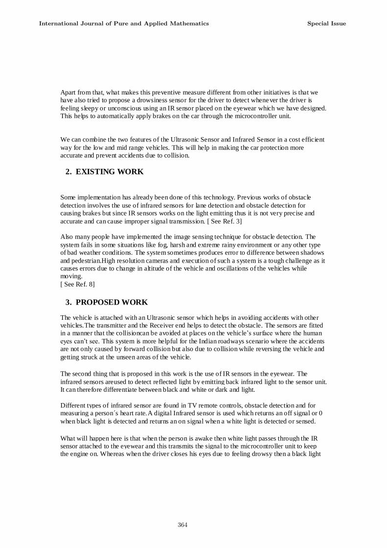
What will happen here is that when the person is awake then white light passes through the IR sensor attached to the eyewear and this transmits the signal to the microcontroller unit to keep the engine on. Whereas when the driver closes his eyes due to feeling drowsy then a black light
International Journal of Pure and Applied Mathematics Special Issue
364
starts to pass through the IR sensor thus sending 0 signal to the control unit which automatically applies a brake in the car system.
4. MAIN HARDWARE COMPONENTS The main hardware components include ultrasonic sensors at the front and the back, a buzzer or alarm for alerting the driver, Arduino microcontroller unit, RF Module for the wireless
connection between the car model and the remote controller unit, DC motors of 12 Volts rating for the wheels, Infrared sensors for the eyewear. An LCD displays the obstacle or the object
distance.
4.1 Control Unit The Arduino Uno is a microcontroller board based on the ATmega328. There are a total of 14 Input and Output pins in ATmega328 with 6 as PWM outputs and 6 as analog inputs.There is a
reset button and a power jack for the unit. It houses a 16 MHz crystal oscillator with a USB connection and an ICSP header. Everything that is needed to assist the microcontroller is already present. We only need to provide power via a USB cable or using an AC-to-DC adapter.
Features of the Arduino Uno:
Microcontroller is ATmega328P based and Operating at a Voltage of 5Volts. The Input Voltage (recommended) is 7-12Volts and Input Voltage within limits is 6-20Volts. The Input and Output Pin gives DC Current of40 milleAmperes. There is a Flash Memory availableof 32 KB out of
which 0.5 KB is used up by theboot loaderwith availableSRAM of 2 KB and an EEPROM of 1 KB is provided inside.
International Journal of Pure and Applied Mathematics Special Issue
365
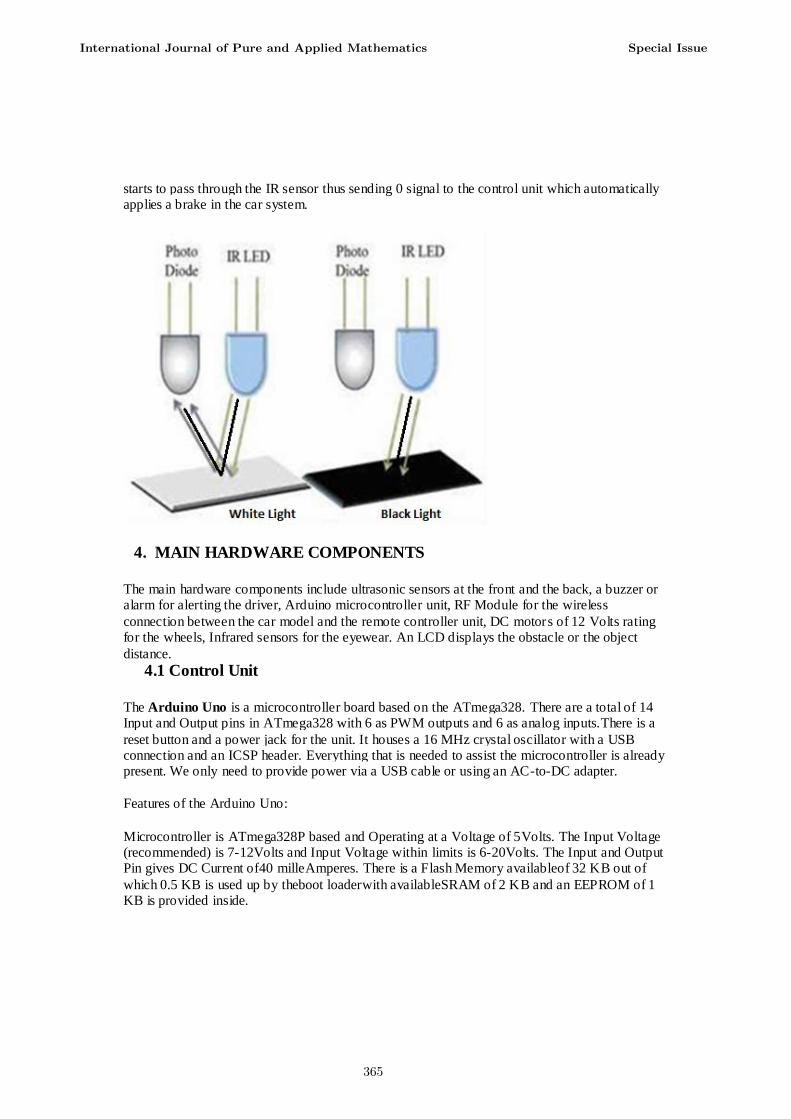
Fig:-Arduino Uno Schematic
4.2 Ultrasonic Sensors
Two Ultrasonic sensors known as HC-SR04 are used in this project. It has a range of 2 cm to 400 cm for measurement function without contact. It works at 5Volts of power supply and can have
an accuracy of up to 3mm with effectual angle less than 15°.
The basic working principle:
Input/output triggers used for minimum10us at high level signal. Then the unitinstinctively
forwards eight 40 kHz signals and sense whether there is a returning pulse signal received backto the module unit. If there is a returning signalreceived, through high level then the time of high Input and Output durationcan be calculated as the time from sending ultrasonic to returning back.
Test distance = (high level time×velocity of sound (340M/S) / 2
Pin Definitions:
1. GND Ground (Vss)
2. 5 V 5 VDC (Vdd) 3. SIG Signal (I/O pin)
International Journal of Pure and Applied Mathematics Special Issue
366

International Journal of Pure and Applied Mathematics Special Issue
367
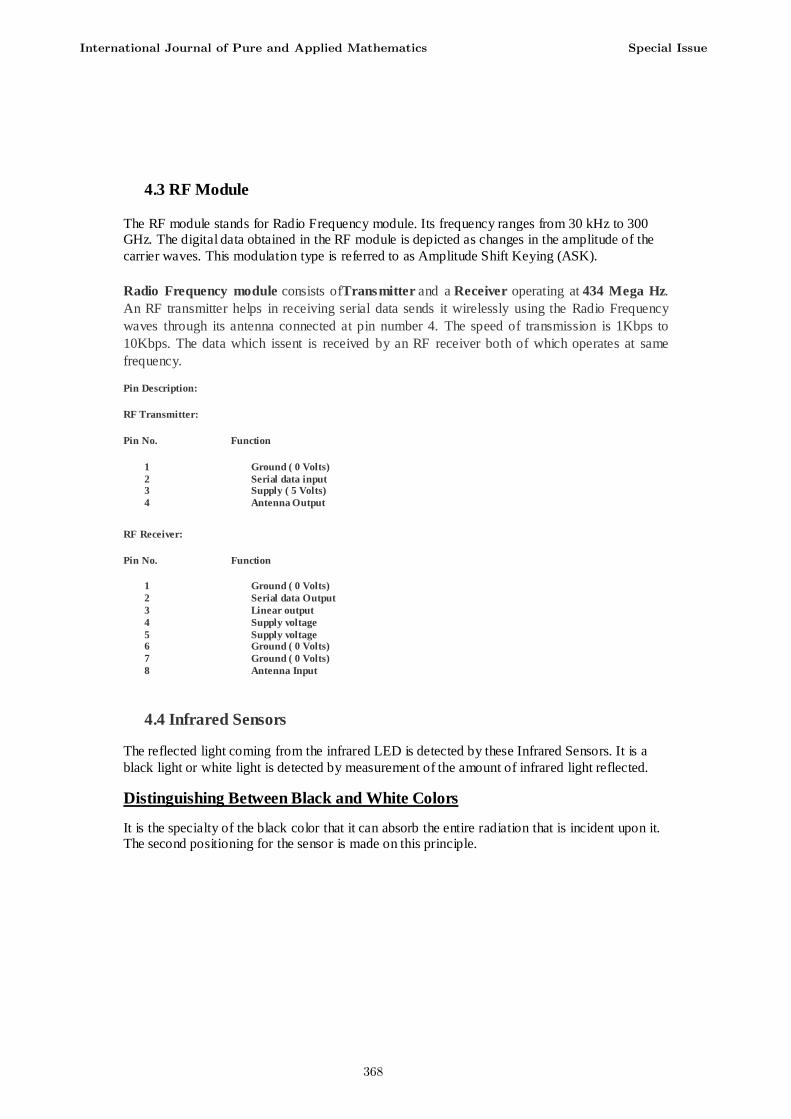
4.3 RF Module
The RF module stands for Radio Frequency module. Its frequency ranges from 30 kHz to 300 GHz. The digital data obtained in the RF module is depicted as changes in the amplitude of the
carrier waves. This modulation type is referred to as Amplitude Shift Keying (ASK).
Radio Frequency module consists ofTransmitter and a Receiver operating at 434 Mega Hz.
An RF transmitter helps in receiving serial data sends it wirelessly using the Radio Frequency
waves through its antenna connected at pin number 4. The speed of transmission is 1Kbps to
10Kbps. The data which issent is received by an RF receiver both of which operates at same
frequency.
Pin Description:
RF Transmitter:
Pin No. Function
1 Ground ( 0 Volts)
2 Serial data input 3 Supply ( 5 Volts)
4 Antenna Output
RF Receiver:
Pin No. Function
1 Ground ( 0 Volts)
2 Serial data Output
3 Linear output
4 Supply voltage
5 Supply voltage 6 Ground ( 0 Volts)
7 Ground ( 0 Volts)
8 Antenna Input
4.4 Infrared Sensors
The reflected light coming from the infrared LED is detected by these Infrared Sensors. It is a
black light or white light is detected by measurement of the amount of infrared light reflected.
Distinguishing Between Black and White Colors
It is the specialty of the black color that it can absorb the entire radiation that is incident upon it. The second positioning for the sensor is made on this principle.
International Journal of Pure and Applied Mathematics Special Issue
368

When the surface of the eye is does not reflect back that is black in color (for example pupil) or other dark color, it absorbs all radiation that is incident up on it. In such as case when no reflected radiation occurs, then on the photodiode there is no incident radiation and the resistance
of the photodiode does not decrease thus not letting the current to flow.
Pin No. Connection Description
1 Output Digital Output (High orLow)
2 VCC Connected to circuit supply 3 Ground Connected to circuit ground
5. BLOCK DIAGRAM
International Journal of Pure and Applied Mathematics Special Issue
369

6. CIRCUIT DIAGRAM
Fig:- Working Model
International Journal of Pure and Applied Mathematics Special Issue
370

Fig:- Remote Controller
7. COMPONENTS
1. Microcontroller(Arduino Uno) Unit
2. Ultrasonic Sensors X 2
3. Infrared Sensors 4. DC Motors (12 volts) X 2
5. RF Module
6. Battery 7. Resistance
8. L293D IC X 2
9. Wheels 10. Voltage Regulator
11. LED X 4
International Journal of Pure and Applied Mathematics Special Issue
371
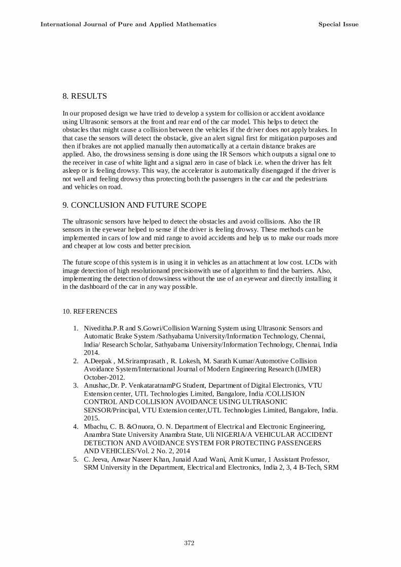
8. RESULTS In our proposed design we have tried to develop a system for collision or accident avoidance
using Ultrasonic sensors at the front and rear end of the car model. This helps to detect the obstacles that might cause a collision between the vehicles if the driver does not apply brakes. In
that case the sensors will detect the obstacle, give an alert signal first for mitigation purposes and then if brakes are not applied manually then automatically at a certain distance brakes are applied. Also, the drowsiness sensing is done using the IR Sensors which outputs a signal one to
the receiver in case of white light and a signal zero in case of black i.e. when the driver has felt asleep or is feeling drowsy. This way, the accelerator is automatically disengaged if the driver is
not well and feeling drowsy thus protecting both the passengers in the car and the pedestrians and vehicles on road.
9. CONCLUSION AND FUTURE SCOPE
The ultrasonic sensors have helped to detect the obstacles and avoid collisions. Also the IR sensors in the eyewear helped to sense if the driver is feeling drowsy. These methods can be
implemented in cars of low and mid range to avoid accidents and help us to make our roads more and cheaper at low costs and better precision.
The future scope of this system is in using it in vehicles as an attachment at low cost. LCDs with
image detection of high resolutionand precisionwith use of algorithm to find the barriers. Also, implementing the detection of drowsiness without the use of an eyewear and directly installing it in the dashboard of the car in any way possible.
10. REFERENCES
1. Niveditha.P.R and S.Gowri/Collision Warning System using Ultrasonic Sensors and Automatic Brake System /Sathyabama University/Information Technology, Chennai,
India/ Research Scholar, Sathyabama University/Information Technology, Chennai, India 2014.
2. A.Deepak , M.Sriramprasath , R. Lokesh, M. Sarath Kumar/Automotive Collision Avoidance System/International Journal of Modern Engineering Research (IJMER)
October-2012. 3. Anushac,Dr. P. VenkataratnamPG Student, Department of Digital Electronics, VTU
Extension center, UTL Technologies Limited, Bangalore, India /COLLISION CONTROL AND COLLISION AVOIDANCE USING ULTRASONIC
SENSOR/Principal, VTU Extension center,UTL Technologies Limited, Bangalore, India. 2015.
4. Mbachu, C. B. &Onuora, O. N. Department of Electrical and Electronic Engineering, Anambra State University Anambra State, Uli NIGERIA/A VEHICULAR ACCIDENT
DETECTION AND AVOIDANCE SYSTEM FOR PROTECTING PASSENGERS AND VEHICLES/Vol. 2 No. 2, 2014
5. C. Jeeva, Anwar Naseer Khan, Junaid Azad Wani, Amit Kumar, 1 Assistant Professor, SRM University in the Department, Electrical and Electronics, India 2, 3, 4 B-Tech, SRM
International Journal of Pure and Applied Mathematics Special Issue
372

University in Electrical and Electronics, India/Voice Based Vehicular Parameter Control/International Journal of Advanced Research in Computer Science and Software
Engineering,Volume 6, Issue 5, May 2016 6. Otieno Vanessa Amondi,Dr. George N. Kamucha, Collision Avoidance System/THE
UNIVERSITY OF NAIROBI SCHOOL OF ENGINEERING DEPARTMENT OF ELECTRICAL AND INFORMATION ENGINEERING 2015.
7. Yatish.P.R,N.S.Shayan,Vishwas.S.Patel,Mr. Manjunath P SLecturer, Dept of Telecommunication, BMSCE, Bangalore.Collision Avoidance for Vehicle Safety 2011.
8. A Practical Obstacle Detection and Avoidance System SumitBadal Srinivas Ravela Bruce Draper Allen Hanson Computer Vision Research Laboratory University of
Massachusetts, Amherst, MA 01002. 9. PranayBhandari, YadneshZagade ,Meet Patel,Parth Desai, NiyatiSoni,UG Students,
Associate professor Atharva College of Engineering,Mumbai,Maharashtra,India/ Ultrasonic Collision Prevention System for Vehicles/International Journal of Advanced
Research in Computer Engineering & Technology (IJARCET) Volume 5 Issue 3, March 2016
10. V. Anupriya,Asst. Professor/Department of ECE, B.LissyRoy,UG Scholar/ECE, V. Dheepti, UG Scholar/ECE, FarhatMasoot, UG Scholar/ECE, Sri Ramakrishna
Enigineering College, Coimbatore, Tamil Nadu, India, Interntional Journal of Engineering Research and Technology(IJERT),Vol. 4, Issue-4, April-2015
11. SumitGarethiya, LohitUjjainiya and VaidehiDudhwadkar, Electronics and Telecommunication Engineering, Symbiosis International University, Pune, India School of Electronics Engineering, VIT University, Chennai, India /PREDICTIVE VEHICLE
COLLISION AVOIDANCE SYSTEM USING RASPBERRY – PI. ARPN Journal of Engineering and Applied Sciences, Vol.10, No. 8, May-2015.
International Journal of Pure and Applied Mathematics Special Issue
373

374