ijrmet v . 6, i 1, n 2015-a 2016 finite element analysis ... · finite element analysis of knuckle...
TRANSCRIPT
IJRMET Vol. 6, IssuE 1, NoV 2015-ApRIl 2016
w w w . i j r m e t . c o m InternatIonal Journal of research In MechanIcal engIneerIng & technology 45
ISSN : 2249-5762 (Online) | ISSN : 2249-5770 (Print)
Finite Element Analysis of Knuckle Joint Pin Using Creo 2.0 Software
Aman DuttDept. of Mechanical Engineering, Lovely Professional University, Phagwara, Punjab, India
AbstractTractor and its trailer is useful equipment in agricultural field. Tractor and trailer are connected together by the means of knuckle joint. Knuckle joint consists of two forks, one attached to tractor and other attached to trailer, both the forks are connected together using pin. Mostly knuckle pin is made of 30C8 material. In present study finite element analysis of knuckle pin is done for 30C8 material using Creo 2.0 software for four different loads and results obtained are compared with composite polymer material i.e Teflon. Results obtained are then compared and suitable conclusions are made.
KeywordsKnuckle Pin, Creo 2.0, 30C8, Teflon
I. IntroductionTractor – trailer is widely used equipment in agricultural field for transportation. Tractor – trailer is joined together by means of knuckle joint which is used to connect two rods which are under tensile force. This joint is preferred as it is easy to mantle and dismantle. This link is also used in pump rod joint, lever and rod connection of various types, valve rod of eccentric valve pump [1].Knuckle joint is a type of hinged joint i.e, it permits the movement between two parts in one plane only. The two parts which need to be joined coaxially shouldn’t separate apart when they are pulled apart. In order to maintain two parts joined together knuckle pin is used.Paper presents the finite element analysis of knuckle pin. Modal is made in Creo 2.0 software and then discretized into small elements and then subjected to suitable boundary conditions. Results are obtained for 30C8 material are then compared with Teflon material and suitable conclusions are made.
II. Literature ReviewNumber of investigations has been done on finite element analysis of knuckle joint and its components. Saurav Das,Vishvendra Bartaria, Prashant Pandey calculated the stresses in knuckle joint using analytical method. It was observed that on changing the pin diameter the load carrying capacity of the pin increases [2]. Dinesh Shinde and Kanak Kalita performed FE analysis of knuckle joint pin used in tractor trailer. Analysis was performed on pin under acceleration and declaration condition using newton’s second law. It was observed the intensity of von misses stress is maximum in case of deceleration [3]. NishantVibhavSexena and Dr. Rohit Rajvaidya performed the study and analysis of knuckle joint with the replacement of material by Teflon. It was observed parts made of composite materials are economical to produce and facilitate cost reduction as compared to metal parts [4].
III. Geometric Modeling and Boundary ConditionNumerical simulation needs 3D geometry of modal under consideration. Modal is divided into small elements known as mesh.
A. GeometryModal under study is knuckle pin as shown in fig. 1. Dimensions of pin is shown in Table 1.
Table 1: Shows The Dimension of Knuckle Pin.Part Dimension
Pin Diameter 25mmPin Head Diameter 37.5mm
Length of Pin 81mm
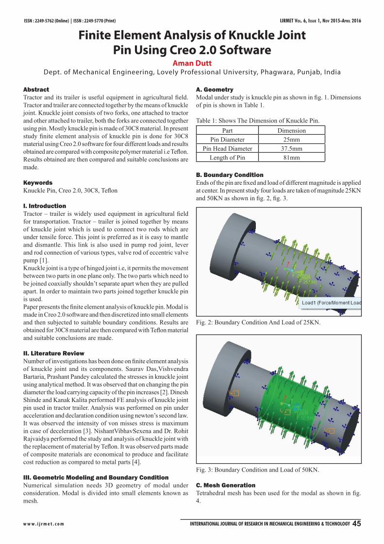
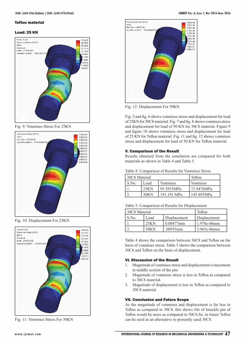
B. Boundary ConditionEnds of the pin are fixed and load of different magnitude is applied at center. In present study four loads are taken of magnitude 25KN and 50KN as shown in fig. 2, fig. 3.
Fig. 2: Boundary Condition And Load of 25KN.
Fig. 3: Boundary Condition and Load of 50KN.
C. Mesh GenerationTetrahedral mesh has been used for the modal as shown in fig. 4.

IJRMET Vol. 6, IssuE 1, NoV 2015-ApRIl 2016 ISSN : 2249-5762 (Online) | ISSN : 2249-5770 (Print)
w w w . i j r m e t . c o m 46 InternatIonal Journal of research In MechanIcal engIneerIng & technology
Fig. 4: Mesh Generation
D. Material SpecificationIn present study, results are calculated for the pin of material 30C8 for the loads and the obtained results are then compared with Teflon material. Properties of 30C8 material and Teflon material are shown in Table 2 and Table 3.
Table 2: Properties of 30C8 Material [2]Young’s Modulus 2×10⁵ MPaPoisson’s Ratio 0.3Yield Strength 200 MPa
Table 3: Properties of Teflon Material [4]Young’s Modulus 5.e+008Poisson’s Ratio 0.46Ultimate Tensile Strength 2.07e+007Compressive Yield Strength 1.5e+007
IV. ResultsSimulation was carried out on two different loads and for two different materials. Simulation has provided the result forvonmises stress and displacement, as shown in figures below.30C8 material
Load: 25KN
Fig. 5: Vonmises Stress For 25 KN
Fig. 6: Displacement For 25 KN.
B. Load: 50KN
Fig. 7: Vonmises Stress For 50KN.
Fig. 8: Displacement For 50KN.
IJRMET Vol. 6, IssuE 1, NoV 2015-ApRIl 2016
w w w . i j r m e t . c o m InternatIonal Journal of research In MechanIcal engIneerIng & technology 47
ISSN : 2249-5762 (Online) | ISSN : 2249-5770 (Print)
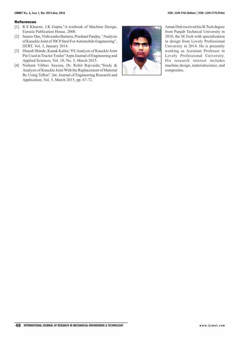
Teflon material
Load: 25 KN
Fig. 9: Vonmises Stress For 25KN
Fig. 10: Displacement For 25KN
Fig. 11: Vonmises Stress For 50KN
Fig. 12: Displacement For 50KN
Fig. 5 and fig. 6 shows vonmises stress and displacement for load of 25KN for 30C8 material. Fig. 7 and fig. 8 shows vonmises stress and displacement for load of 50 KN for 30C8 material. Figure 9 and figure 10 shows vonmises stress and displacement for load of 25 KN for Teflon material. Fig. 11 and fig. 12 shows vonmises stress and displacement for load of 50 KN for Teflon material.
V. Comparison of the ResultResults obtained from the simulation are compared for both materials as shown in Table 4 and Table 5.
Table 4: Comparison of Results for Vonmises Stress30C8 Material Teflon S.No. Load Vonmises Vonmises 1. 25KN 95.5953MPa 72.9476MPa2. 50KN 191.191 MPa 145.895MPa
Table 5: Comparison of Results for Displacement30C8 Material Teflon S.No. Load Displacement Displacement 1. 25KN 0.00477mm 1.978e-06mm2. 50KN .00955mm 3.965e-06mm
Table 4 shows the comparison between 30C8 and Teflon on the basis of vonmises stress. Table 5 shows the comparison between 30C8 and Teflon on the basis of displacement.
VI. Discussion of the ResultMagnitude of vonmises stress and displacement is maximum 1. at middle section of the pin.Magnitude of vonmises stress is less in Teflon as compared 2. to 30C8 material.Magnitude of displacement is less in Teflon as compared to 3. 30C8 material.
VII. Conclusion and Future ScopeAs the magnitude of vonmises and displacement is far less in Teflon as compared to 30C8. this shows life of knuckle pin of Teflon would be more as compared to 30C8.So, in future Teflon can be used as an alternative to presently used 30C8.
IJRMET Vol. 6, IssuE 1, NoV 2015-ApRIl 2016 ISSN : 2249-5762 (Online) | ISSN : 2249-5770 (Print)
w w w . i j r m e t . c o m 48 InternatIonal Journal of research In MechanIcal engIneerIng & technology
References[1] R.S Khurmi, J.K Gupta,"A textbook of Machine Design,
Eurasia Publication House, 2008.[2] Saurav Das, Vishvendra Bartaria, Prashant Panday, “Analysis
of Knuckle Joint of 30C8 Steel For Automobile Engineering”, IJERT, Vol. 3, January 2014.
[3] Dinesh Shinde, Kanak Kalita,“FE Analysis of Knuckle Joint Pin Used in Tractor Trailer”Arpn Journal of Engineering and Applied Sciences, Vol. 10, No. 5, March 2015.
[4] Nishant Vibhav Saxena, Dr. Rohit Rajvaida,“Study & Analysis of Knuckle Joint With the Replacement of Material By Using Teflon”, Int. Journal of Engineering Research and Application, Vol. 5, March 2015, pp. 67-72.
Aman Dutt received his B.Tech degree from Punjab Technical University in 2010, the M.Tech with specialization in design from Lovely Professional University in 2014. He is presently working as Assistant Professor in Lovely Professional University.His research interest includes machine design, materialscience, and composites.