i.l. 41-669a toc · 1.3.1 mrc-t outer chassis this is an ft-32 case, where all the input/output...
TRANSCRIPT


I.L. 41-669A
1-2 (5/95)
1. 2. MRC-T FEATURES
1.2.1 Standard Features• Multiple-Shot Reclosing
1 - 4 Instantaneous or time delay reclosures
• Reclosure dead time (settable for each reclose)0.01 - 250 seconds
• Selectable reclosing initiate signal52b onlyReclose Initiate (RI) only52b or RI52b and RI
• Reclosure block feature setting selectable
• Ac or dc control powered
• Close contact closure energizing time (reset by removal of 52b)0.01 - 2 seconds
• Switched synchronism (enabled by external input) allow:Hot Line Dead Bus (HLDB) voltage check and/orHot Bus Dead Line (HBDL) voltage check and/orSynchronism (Sync) to be used with:Maximum Wait Time for voltage check or Sync, - 990 secondsMinimum Sync Condition Time Duration, 0.01 - 20 secondsWithin any reclose sequence
• Drive to Lockout input for manual trips and breaker failure or bus lockout relay in-put
• Reclosure skip input
• Hold input to freeze reclosing cycle
• Failed reclose timer:1 - 250 seconds
• Maximum cycle timer:1 - 990 seconds
• Follow Breaker function (52b status monitored during reclosing sequence)
• Breaker operation and maintenance monitoring:Settable cumulative reclosures before alarm, 0 - 990 reclosuresBreaker limit operations:
Maximum reclosures (Max Count) in Duration time, 0 - 250 reclosuresDuration time limit, 1 - 250 minutesRecovery time, after Max Count exceeded, 1 - 250 minutes
• Front panel LED indication:RECLOSING IN SERVICE LOCKOUT FAILED RECLOSESYNCHRONISM HBDL HLDB (supplied with sync-check option)
• Recloser event records (recorded as targets)Reclosure numberNumber of attempts to completionResult, successful or lockoutTime of eventSynchronism information (if synchronism used)
• Target data available through communications port
• Real time clock to time stamp reclosing events

I.L. 41-669A
(5/95) 1-3
• Four programmable inputs (any combination of OR’s and AND’s)
• Two programmable logic outputs (fed by the programmable inputs)
• Alarms for:Relay FailureIntermediate |LOCKOUTReclosure FailureReclosure LOCKOUTReclosing in progress
1.2.2 Optional Features
• Internal Sync/voltage checking logic including:Settable “hot” voltage range30 - 70 volts for 70 volt input relay or50 - 120 volts for 120 volt input relay
• Settable “dead” voltage range0 - 30 volts for 70 volt input relay or0 - 50 volts for 120 volt input relay
• Settable HLDB and/or HB DL and/or Sync for each reclosure sequenceSettable maximum angle for synchronism, 0 - 60 degreesMaximum Wait Time for voltage check or Sync, 0 - 990 secondsMinimum Sync Condition Time Duration, 0.01 - 20 seconds
• Line and bus voltage input for either 70 volts or 120 volts
• Man-Machine Interface consisting of 2 X 16 character LCD display and four push-buttons to:
Review or change settingsReview two most recent targetsReview or reset breaker operations and other countersReview results of self-checking testDisplay status of relay, Ready, Disabled or LockoutDisplay reason for relay being in Lockout stateTest output contacts, input circuit integrity and LED operation
• Front communications port, RS232C, 9 pin DCE connector, settable for 300 -19,200 bits/second
• Choice of rear communications port, either RS232C or INCOM network type (defaultis RS232C)
• Horizontal or vertical mounting
• Choice of 48, 125 or 250 volts dc control power
1. 3. MRC-T CONSTRUCTION
The standard nomenclature for ABB relay protection equipment is as follows:
• Cabinet – contains fixed-racks, swing-racks, or open racks
• Rack – contains one or more chassis (e.g., the MRC-T)
• Chassis – contains several modules (e.g., Microprocessor or Power supply)
• Module – contains a number of functional circuits (on printed circuit board)
• Circuit – a complete function on a printed circuit board (e.g., analog-to-digital con-version)

I.L. 41-669A
1-4 (5/95)
The MRC-T relay assembly consists of an outer-chassis and an inner-chassis whichslides into the outer-chassis. The MRC-T can be mounted either vertically (Figure 1-2)or horizontally where the only changes are the nameplate and the 19 inch adapterplate (Figure 1-3).
All of the relay circuitry, with the exception of the first-line surge protection, is mount-ed on the inner chassis, to which the front panel is attached. The outer chassis has abackplane, which is a receptacle for external connections, including the rear commu-nication adaptor (Figure 1-4). The FT-10 switches allow convenient and safe discon-nection of close contact output, ac and dc input circuits, and provide for injection oftest signals.
1.3.1 MRC-T Outer Chassis
This is an FT-32 case, where all the input/output signals are surge protected. All ex-ternal connections are made through the rear of the case.
The outer chassis (Figure 1-5) consists of 2 surge protection modules, a backplanesurge protection module, a metal case, FT-switches and a communication interfaceconsisting of a PONI box (INCOM or RS232C) mounted on the back of the case fromthe inside on the backplane module (Figure 1-4).
1.3.2 MRC-T Inner Chassis
• The inner chassis (Figure 1-7) consists of a frame, 2 switchjaws and the followingmodules:
• I/O Module (Bottom):Consisting of 4 contact inputs and 2 contact outputs (Figure 1-8).
• I/O Module (Top):Consisting of 4 contact inputs and 4 contact outputs (Figure 1-9).
• Microprocessor Module:Consisting of a microcontroller (16 bits Intel 80C196 at 10 MHz), two EPROM pro-gram memory chips; two RAM chips, and EEPROM for data retention, a real timeclock with a chip battery and indication LED’s (Figure 1-10).
• Power Supply/I/O ModuleThis is an isolated switching power supply capable of supplying +5 Vdc for micro-controller and surrounding IC logic, 12 Vdc for reference voltages and +24 Vdc forcommunication. The two analog inputs for synchronism check, 4 contact inputsand 2 contact outputs for programmable logic are also contained in this module.(Figure 1-11).
• Three different styles of power supply boards are required to accommodate the inputvoltage ranges listed in Table 1-1:
• Man-machine interface/display module (Optional):Consisting of a 2-line, 16 character per line Liquid Crystal Display (LCD), and fourpush-buttons for setting data entries (Figure 1-12).
• Front RS232C Communication Module (Optional):providing front RS232C Communication interface to microprocessor module (Figure1-13).

I.L. 41-669A
(5/95) 1-5
1. 4. RECLOSE/SYNCHRONISM CHECK SOFTWARE
The reclose/synchronism check software includes the following functions:
a. All the reclose and synchronism check functions.
b. All the MMI functions.
c. Programmable logic input/output function.
d. Reclosing event recording.
e. Test functions.
1. 5. SELF-CHECKING SOFTWARE
Self-checking software includes the following functions:
a. Program Memory Check-sumImmediately upon power-up, the relay does a complete EPROM check-sum of programmemory. Afterwards, the MRC-T continually verifies the program memory check-sum.
b. Power Up RAM Check:Immediately upon power-up, the relay does a complete test of the RAM data memory.
c. EEPROM Check:Settings are stored in EEPROM in three identical arrays. These arrays are continuouslychecked by the program. If any of the three array entries disagree, an EEPROM failure isdetected.
1. 6. UNIQUE REMOTE COMMUNICATION PROGRAM (RCP)
Special software, RCP, is provided for obtaining fault, metering and current settingsdata as well as sending data to the REL 301/302. RCP can best be described as a userfriendly way of using a personal computer (PC) to communicate with ABB protectiverelays by way of pull-down menus. By coupling a computer with the appropriate com-munications hardware, it is possible to perform all relay setting and data interactions.RCP is required to communicate with the REL 301/302 via the communication port(s).Refer to the RCP Instruction Manual, I.L. 40-603, for detailed information. If you wantto update your RCP, use the ABB bulletin board. More information about using thebulletin board is on following page.
Table 1-1:Control Power Operating Range
NominalBattery (Vdc)
Input Range(Vdc)
48/60110/125220/250
38 - 7088 - 145176 - 290

I.L. 41-669A
1-6 (5/95)
ABB BULLETIN BOARDNOW ON LINE
To obtain the latest RCP communication software, please call the ABB Power T&DCompany Inc., Relay Division bulletin board system via modem at:
(800) 338-0581 or (305) 755-3250
Using configuration settings 300 - 14,400 bits/second, 8 data bits, 1 stop bit, noparity, and full duplex. Once the connection is established and login is completed,from the TOP menu choose L - Library of Files. Then from the Library of Files menuchoose D - Down Load File, filename RCPxxxx.EXE (where xxxx is the most currentversion number e.g., 175D).

I.L. 41-669A
(5/95) 1-7
Figure 1-2. MRC-T Layout (Vertical)
Sub 11357D63Sheet 4 of 5

I.L. 41-669A
1-8(5/95)
Figure 1-3. MRC-T Layout (Horizontal)
Horizontal Mounting Plate Sub 11357D63Sheet 5 of 5


I.L. 41-669A
(5/95) 1-13
Figure 1-8. Bottom I/O Module
J2, J10J4, J5J6, J7J8, J9
52bDrive to LOCKOUTRBRI
DC
AC
52b Drive to LOCKOUT RB RI Failure Alarm
DC
AC
48
250
125
48
250
125
48
250
125
48
250
125
Sub 981614C10Sheet 2 of 2

I.L. 41-669A
1-14 (5/95)
Figure 1-9. Top I/O Module
J14, J3J7, J6J8, J9J11, J10
SKIPHOLDSYNC CHECKMAN CLOSE
NO
NC
ACAC DC
NO
NC
NC NO
NC NO
IN PROG
LOCKOUT ALARM
FAIL RECLOSE
SKIP
HOLD
SYNC-CHECK
MAN CLOSE
48
250
125
48
250
125
48
250
125
48
250
125
INT LO ALARM
Sub 961614C13Sheet 2 of 2

I.L. 41-669A
(5/95) 1-15
Figure 1-10. Microprocessor Module
Sub 991614C06Sheet 2 of 2
R7In for 60 HzOut for 50 Hz

I.L. 41-669A
1-16 (5/95)
Figure 1-11. Power Supply Module
250
125
48
250
125
48
250
125
48
250
125
48
AC DC
NC
NO
DC
NC
IN C/SYNC
IN D
OUT 1
OUT 2
IN A/HLDB
IN B/HBDL
Sub 991614C07Sheet 4 of 4

I.L. 41-669A
(5/95)1-17
Figure 1-12. Man-Machine Interface (display) Module (Optional)
Sub 11613C69Sheet 2 of 2

I.L. 41-669A
1-18 (5/95)
Figure 1-13. Front RS232 Communication Module (Optional)Mounted on rear of Microprocessor Module
Sub 991614C94

I.L. 41-669A
(5/95) 1-19
Figure 1-14. Backplane Module
Sub 981614C41Sheet of


I.L. 41-669A
(5/95) 2-1
Section 2. SPECIFICATIONS
2. 1. TECHNICAL
ac Voltage (VLN) at 60 Hz 70 Vrms(VLL) at 60 Hz 120 Vrms(VLN) at 50 Hz 63.5 Vrms
Rated Frequency 50 or 60 Hz
Maximum Permissible ac Voltage
• Continuous 1.5 x nominal voltage
• 10 Second 2.5 x nominal voltage
dc Battery Voltages
Nominal Operating Range48/60 Vdc 38 - 70 Vdc110/125 Vdc 88 - 145 Vdc220/250 Vdc 176 - 290 Vdc
dc Burdens: Battery 7 W normal
ac Burdens: Voltage input 0.02VA at 70 Vac / phase
2. 2. EXTERNAL CONNECTIONS
Terminal blocks located on the rear of the chassis suitable for #14 square tongue lugs.
Wiring to FT-10 switches suitable for #12 wire lugs.
2. 3. CONTACT DATA
Close Contact - make & carry 30 A for 1 second, 10 A continuous capability, break 50watts resistive or 25 watts with L/R = .045 seconds.
All other contacts are “Non-trip” rated.
• 3A Continuous
• 0.1A Resistive Interrupt Capability
Supports 1000 Vac across open contacts
contacts also meet IEC - 255-6A, 1EC - 255-12, IEC -255-16, BS142-1982.
2. 4. CONTACT INPUT VOLTAGE RATINGS
All contact inputs listed below are rated for ac or dc operation
• Reclose Initiate • Freeze Reclosing • Reclosure Block
• Skip Reclosure • Drive to Lockout • Programmable Inputs 1-4
• 52b • Manual Close • External Sync-Check

I.L. 41-669A
2-2 (5/95)
2. 5. CHASSIS DIMENSIONS AND WEIGHT
Height: 15.125" * 7.00"Width: 5.876" * 19.00"Depth: 6.626" * 6.626"Weight: 19 lb.
* For Horizontal Mount: 19 inch adapter plate
2. 6. ENVIRONMENTAL DATA
Ambient Temperature Range
• For Operation -20°C to +55°C• For Storage -40°C to +80°C
Dielectric Test Voltage 2.8 kV, dc, 1 minute (ANSI C37.90.0, IEC 255-5)
Impulse Withstand Level 5 kV peak, 1.2/50 msec, 0.5 joule (IEC 255-5)
Fast Transient Surge Withstand Capability 4 kV, 5/50 nsec (IEC 801-4); 5kV 10/150 nsec (ANSIC37.90.1)
Oscillatory Surge Withstand Capability 2.5 kV, 1 MHz (ANSI C37.90.1, IEC 255-6)
EMI Volts/Meter Withstand 25 MHz-1GHz, 10V/m withstand (Proposed ANSI C37.90.2).

I.L. 41-669A
(5/95) 3-1
3. 1. THEORY OF OPERATION
The following is an explanation of MRC-T relay synchronism measurements and oper-ation.
3.1.1 Synchronism Checking
MRC-T can be supplied with internal synchronism-check/voltage check (Hot BusDead Line or Hot Line Dead Bus) logic or can be supervised with external synch/HBDL/HLDB inputs. For relays supplied with internal synchronism checking logic,supervision of MRC-T reclosing is settable for synchronism and/or HBDL and/orHLDB for each reclosing attempt.
MRC-T synchronism checking logic utilizes a “windshield wiper” characteristic (seeFigure 3-1). This is, a combination of synchronism voltage, magnitude measurementand voltage, angle difference measurement. Both magnitude and angle difference mea-surement must be within the user’s set range to produce synchronism check permis-sion of reclosing.
Sync-Angle
WINDSHIELD WIPER CHARACTERISTIC
VMAX
VLineVMIN VBus
DEAD
Figure 3-1
HOT
3.1.2 Intermediate Lockout
With either synchronism check logic (internal or external) in use, an IntermediateLockout condition, and alarm output, can be achieved to “wait” for the synchronismand/or voltage check condition to be met. Intermediate Lockout (“Int. Lo”) is a statewhich can only be selected on the last reclosure of the set reclose sequence. “Int. Lo”state exists indefinitely and MRC-T will return to the Ready Mode or Lockout Modeonly if sync and/or voltage check condition set is met.
Section 3. APPLICATIONS AND ORDERING INFORMATION
If the MRC-T is not suppliedwith internal synchronismchecking logic, reclosing can besupervised by an externalsource of synchronism and/orvoltage check. Three inputs,HLDB, HBDL and Sync can beused, similar to the quantitiesproduced by the internal syn-chronism logic, to supervise re-closing. MRC-T checks theinputs for the presence of ratedvoltage to determine if the cor-responding reclosing permis-sion is present. Selection ofexternal synchronism input useis via the setting "Sync Set?"being set to "Switches".

I.L. 41-669A
3-2 (5/95)
3. 2. APPLICATION
The MRC-T relay is used for automatic reclosure of an ac or dc electrically operatedcircuit breaker after it has been opened by a protective relay action. The basic styleoperates with 48, 125, or 250 Vdc or 120 or 240 Vac (50 or 60 Hz) input control volt-age. The relay may be adjusted to provide several reclosures at predetermined inter-vals, so that in case the breaker does not remain closed after the first reclosure,additional reclosures can be made. The first reclosure usually is an immediate reclo-sure. System operation experience has shown that the majority of faults are of a tem-porary nature, such as lightning, flashovers, and will not be reestablished after aninterruption of the fault current. Consequently, service interruption can be minimizedby the use of an immediate reclosure. However, the first reclosure may be delayed (bysetting) if desired.
In case the protective relay operates again after the first reclosure, the reclosing relaywill close the breaker at selected intervals. The relay may be adjusted to make anynumber of reclosures up to a total of four. If the breaker does not remain closed afterthe final reclosure, the relay goes to “LOCKOUT”. The breaker must then be closedmanually or by control switch. However, if the breaker remains closed after any auto-matic reclosure, the relay will, after the reset time, advance to and stop at the “READY”position, where the relay is in readiness to repeat the cycle.
For any automatic reclosing application, the underlying factors for breaker interrupt-ing ability should be checked when choosing any particular reclosing cycle. Also, whenusing immediate first reclosure, it is necessary that the protective relays open theircontacts before the breaker contacts make again and that sufficient delay exists to as-sure that the arc has become deionized.
The MRC-T relay is intended for use in transmission or subtransmission applicationsand may optionally be equipped with internal synchronism-check (including voltagesupervision HBDL and HLDB). It will contain:
1. Multi-shot reclosing.2. Reclose initiate and block features.3. IntermediateLOCKOUT to allow remote line test and final close with synchro-
nism check supervision.4. External synchronism input.5. “LOCKOUT ” input for bus faults, breaker failure manual trips, etc.6. “LOCKOUT ” input to freeze all timing.7. “LOCKOUT ” input to skip reclosure.8. “Manual Close” input for closing during LOCKOUT.9. 8 programmable inputs (any combination of OR’s and AND’s).10. 2 programmable outputs (fed by the programmable inputs).11. Alarms for:
Check failureIntermediate LOCKOUTReclose failureReclose LOCKOUTReclosing in progress
12. RS232C/PONI or INCOM/PONI Communications.

I.L. 41-669A
(5/95) 3-3
3. 3. MRC-T CATALOG NUMBERS
Table 3-1
MRCT 1 – 4 MRCT V 1 S P R L
MOUNTING
Horizontal5
H
Vertical V
BATTERY VOLTAGE
48 Vdc 4
125 Vdc 6 1
250 Vdc 2
RECLOSING
Multi-shot Reclosing R
Multi-shot Reclosing w/sync-check (70 V input) 7 S
Multi-shot Reclosing w/sync-check (120 V input) T
PROGRAMMABLE LOGIC (I/0)
2 Relays w/(1) Form-C Contact 8 P
COMMUNICATIONS PORT (Rear)
Flexible (PONI-rear mounted)
INCOM Network C
RS232C (Default)9
R
RS232C with IRIG-B/Input B
FRONT PANEL INTERFACE
LCD Display L
RS232C Port (9-Pin DCE Connector)10
R
Both B
None N
RELAY COLOR
Black (Default Color) 11
Beige E
FT Test Plug-Item ID #13B8453G05
Communication Cable Kit Item ID #1504B78G01
❑ ❑ ❑ ❑ ❑ ❑ ❑

I.L. 41-669A
(5/95) 4-1
4. 1. SEPARATING THE INNER AND OUTER CHASSIS
It is recommended that the user of this equipment becomes acquainted with the infor-mation in these instructions before energizing the MRC-T and associated assemblies.Failure to observe this precaution may result in damage to the equipment.
All integrated circuits used on the modules are sensitive to and can be damaged by thedischarge of static electricity. Electrostatic discharge precautions should be observedwhen operating or testing the MRC-T.
Use the following procedure when separating the inner chassis from theouter chassis; failure to observe this precaution can cause personal inju-ry, undesired tripping of outputs and component damage.
a. Unscrew the front cover knob and remove cover.
b. Open all FT switches.
c. Release frame latches by pushing the top and bottom latches inward towards the centerof the relay.
d. Slide out the inner chassis.
e. Reverse procedures above when replacing the inner chassis into the outer chassis.
4. 2. TEST PLUGS AND FLEXITEST (FT) SWITCHES
Test Plugs are available as accessories. They are inserted into the FT-10 switches forthe purpose of System Function Tests.
4. 3. EXTERNAL WIRING
All electrical inputs/outputs are made through the back of the MRC-T. Table 4-1 illus-trates where the various input/output signals are located. The vertical MRC-T is used asa reference in the Connection Specification Chart (similarly for the horizontal MRC-T).
! CAUTION
! WARNINGDo Not Touch the outer contacts of any FT-10 switch;they may be energized.
Section 4. INSTALLATION AND OPERATION

I.L. 41-669A
4-2 (5/95)
TABLE 4-1CONNECTION SPECIFICATION CHART
FOR MRC-T
INPUT/OUTPUTS LOCATION
SIGNAL INPUTS ( +, - )
RIRBDRIVE TO LOCKOUT52bMAN CLOSESYNC CHECKHOLDSKIPIN A/HLDBIN B/HBDLIN C/SYNCIN D
FT-5, FT-9FT-6, FT-9FT-7, FT-9FT-8, FT-9FT-16, FT-20FT-17, FT-20FT-18, FT-20FT-19, FT-20TB2-1, TB2-2TB 2-3, TB2-4TB2-5, TB2-6TB2-7, TB2-8
ANALOG INPUTS
POWER SUPPLYLINE VOLTAGE (VLINE)BUS VOLTAGE (VBUS)
FT-10, FT-9TB1-3, TB1-4TB1-1, TB1-2
CONTACT OUTPUTS
CLOSE RELAYALARM RELAYINT LO ALARMFAILED RECLOSELOCKOUTIN PROGOUT 1OUT 2
FT-1, FT-2FT-3, FT-4FT-11, FT-12FT-11, FT-13FT-11, FT-14FT-11, FT-15TB1-5, TB1-6TB1-7, TB1-8
COMMUNICATION CONNECTIONThe INCOM or RS-232 PONI (Product Operated NetworkInterface) Communication box is mounted on the inside of thecase to the backplane module. The RS-232 or INCOM cableis connected to the PONI from the back of the case (locatedin the upper section of the backplate).
FRONT COMMUNICATION (OPTIONAL)The front RS-232 communication DB-9 connector is locatedon the front name plate directly below the MMI (display).
4. 4. FRONT PANEL OPERATION
4.4.1 LED Indicator Functions
The MRC-T comes with LEDS onthe front panel. They indicate thestate of reclosing operation andsynchronism check. The functionof each LED is described in Table4-2.
4.4.1.1 LED and Display Reset
The push-button labeled RESET isused to reset the latched “FAILEDRECLOSE” LED, fail reclose con-tact output and send the displayto “READY” mode, or “LOCKOUT”mode.
4.4.2 Front Communications Port (Optional)Enable Push-button
This pushbutton will activate theRS 232 front communication mod-ule. When communicating withthe relay via 9 pin front panel con-nector, the rear INCOM or RS 232communication will be inopera-tive. See section 4.9 for further de-tails regarding front communi-cation.
4.4.3 Man-Machine-Interface (MMI) (Optional)
The MMI consists of a 2-line 16-character per line LCD display, 4push-buttons (SELECT, LOWER,RAISE, ENTER).
4.4.3.1 MMI Modes of Operation
The MMI provides a convenient means of checking the settings, targets, counter sta-tus and relay operations during a reclosing cycle.
The LCD display is divided into three fields: Function, Value, and Mode.
FunctionValue
Mode

I.L. 41-669A
(5/95) 4-3
The seven modes of operation, areshown at the top right of the dis-play. The 4 push-buttons labeledSELECT, LOWER, RAISE, and EN-TER, are used to interface with theMRC-T relay menu and settings.
The default mode (Ready, Lockoutor Disabled) is automatically re-turned to when no push-buttonhas been depressed for 2 minutes.By keeping the SELECT push-but-ton depressed, the list of modes isscrolled in the sequence shown inTable 4-3, at approximately a onesecond rate. For each selectedmode, the corresponding functionscan be scanned (also every second)with the LOWER and RAISE push-buttons.
A. Ready Mode
In normal condition, the relay is in“READY” mode, ready to start a re-closing sequence as soon as the re-closure 1 initiation condition isdetected.
When a reclosing cycle starts, theMRC-T goes through the selectedlogic until either back to “READY”mode, in case of successful reclos-ing, or to “LOCKOUT” mode, if forany reason, no further reclosingcan be attempted.
B. Settings Mode [SET]
Change the mode to [SET] usingthe SELECT push-button. The listof available functions (see Table 4-5) can then be scrolled through for-wards and backwards using theLOWER and RAISE push-buttons.The Function appears on the upperleft of the display, and the Value onthe second line.
Reclosures4 recl
SET
MODE DESCRIPTION AS DISPLAYED
READY System ready to start a reclosing READYsequence. The MRC-T must be in MRC-T VX.XXthis display mode in order to operate.When in the READY state, the defaultmode is the READY mode.
SETTINGS Check and/or change settings [SET]
TARGETS Lists the data related to the two [L-TR] or [P-TR]last reclosing cycles.
STATISTIC List the status of the different [MEM]counters.
TEST Shows selftest status and allows [TEST]the testing of output contacts andLEDs.
LOCKOUT Displays the reason for being in LOCKOUTlockout state. When in the Reason for LockoutLOCKOUT state, the default mode is the LOCKOUT mode.
DISABLED MRC-T disabled from “MRC-T” MRC-T DISABLEDsetting. When in the DISABLED state, Check settingthe default mode is the DISABLED mode.
TABLE 4-3MMI DISPLAY MODES
TABLE 4-2FRONT PANEL LED INDICATOR CHART
RECLOSING INSERVICE
ON when dc power is on, andrelay is not disabled.
LOCKOUT ON when reclosing logic isin LOCKOUT state.Associated with LOCK-OUT output contact.
FAILED RECLOSE ON after a FAILEDRECLOSE. Can becleared by depressing“RESET” push-buttonor via remote communi-cation reset LED. Asso-ciated with fail reclosecontact output.
SYNCHRONISM(*)
ON when Bus & Line volt-ages are in Synchronism.
HBDL (* ) ON when Bus is Live andLine is Dead.
HLDB (* ) ON when Line is Live andBus is Dead.
(*) The 3 lower LEDs are present only with the Synch-Check Option andthe “SYNC SET” setting has been enabled.

I.L. 41-669A
4-4 (5/95)
The corresponding value can be changed by pressing the ENTER push-button once.An underscore dash will then flip alternatively between the first and last characters onthe second line. At this point, other values for the same function can be scrolled
through by depressing the LOWER or RAISE push-button. When the desired value isreached, select it by pressing ENTER until VALUE UPDATED shows on the display.After the value is updated the system then returns to the Function scroll state.
Scrolling proceeds at a faster rate after having continuously held down either buttonfor about 3 seconds. At the end of a setting session, return to “READY” mode by push-ing the SELECT push-button until the ready mode appears on the display.
In order to restore the original value while in the middle of the scrolling values, pressSELECT instead of ENTER, the system returns to the Function scroll state, withoutupdating the setting. In the function scroll state, a jump to the next mode is performedby pressing SELECT.
Settings Description
Refer to Table 4-5 for the complete list of settings with ranges. It is advised to adjustthe settings in the order given in the list (i.e. using the RAISE push-button to move tothe next setting) since some settings might be disabled by certain values. For example,selecting 2 reclosures disables the display of settings for reclosures 3 and 4. Likewise,when a function works in conjunction with a timer, disabling the function hides thetimer setting.
C. Targets Mode [L-TR or P-TR]
Change the mode to Targets using the SELECT push-button. The relay saves the re-closing events that have taken place during the last 2 reclosing sequences for front dis-play purpose.
The last reclosing sequence is referred to as “L-TR”, and the previous one as “P-TR” inthe mode field of the display. Internally, the 16 last targets are recorded and can bechecked remotely via one of the communication port interfaces.
For each of the sequences, the function field displays the reclosure number, the valuefield displays the corresponding event. The list of the possible messages or causes forsuccessful and unsuccessful reclosures is shown in Table 4-4.
Reclosures SET
— 4 recl —
Target Event As displayed
Close CloseFollow Breaker Follow BrReclose Block Input Recl BlockNo HLDB, No HBDL orNo Synch-check No SyncSkip Input Present SkipManual Close CloseManual Close No Sync
TABLE 4-4Target Displays
To scroll the list of targets, depress theLOWER or RAISE push-buttons.
With the Synch-check option, each tar-get is accompanied with the line andbus voltages, and the angle betweenthem at the time the target was recorded(at reclosing in case of a closure, or atthe time the reclosure was skipped forthe given reason).

I.L. 41-669A
(5/95) 4-5
TABLE 4-5SETTING DISPLAY
Setting FunctionDisplayed
ValuesDisplayed
FactoryDefault
Synchronism Functions Enable Sync Set? No/Yes/Switches No
* “Hot” Voltage Threshold VMax30-70 in 1 Volt Steps50-120 in 1 Volt Steps+
53 Volts92 Volts
* “Dead” Voltage Threshold VMin0-30 in 1 Volt Steps0-50 in 1 Volt Steps +
13 Volts23 Volts
* Maximum Angle For Synchronism Sync Angle 0-60 in 1O Steps 20 O
*Present Sync / HLDB /HBDLMinimal Condition Duration
Sync Time0.01-0.99 in 0.01 Second Steps1.0-9.9 in 0.1 Second Steps10-20 in 1 Second Steps
2.0 sec
Number of Reclosures Reclosures 0-4 recl 4 recl
*
*
*
*
Reclosure 1, 2, 3 and 4 parametersReclosure 1 parameters
-Reclosure Initiation
-Reclose Block
-Reclose Dead Time
-Reclose on HLDB
-Reclose on HBDL
-Reclose if Synchronism
-Max Wait Time for aHBDL, HLDB or SynchronismCondition (only available whenRecl1 Sync set toYes).
Recl 1
Recl1 RB
Recl1 Time
Recl1 HLDB
Recl1 HBDL
Recl1 Sync
Recl1 Wait
52b Only/RI Only/52b and RI/52b or RI
No / Yes
0.01-0.99 in 0.01 second steps1.0-9.9 in 0.1 second steps10-250 in 1 second steps
No / Yes
No / Yes
No / Yes
0-99 in 1 Second steps100-990 in 10 Second stepsNo time limit (Infinite Time)
52b Only
No
0.50 sec
No
No
No
60 sec
* Available only with Sync-check Option or when using external sync input (Sync Set ? = Switches).+ Ranges of 120 volt synchronism voltage, style relay only.
I.L. 41-669A
4-6 (5/95)
*
*
*
*
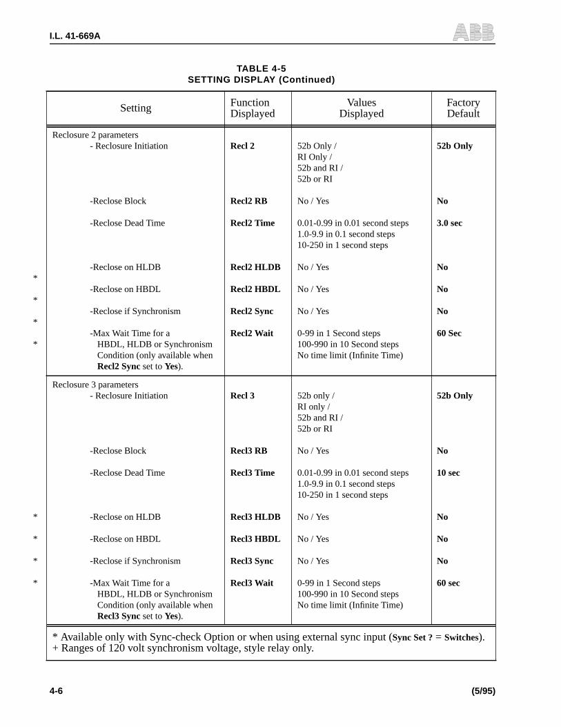
Reclosure 2 parameters- Reclosure Initiation
-Reclose Block
-Reclose Dead Time
-Reclose on HLDB
-Reclose on HBDL
-Reclose if Synchronism
-Max Wait Time for aHBDL, HLDB or SynchronismCondition (only available whenRecl2 Sync set toYes).
Recl 2
Recl2 RB
Recl2 Time
Recl2 HLDB
Recl2 HBDL
Recl2 Sync
Recl2 Wait
52b Only /RI Only /52b and RI /52b or RI
No / Yes
0.01-0.99 in 0.01 second steps1.0-9.9 in 0.1 second steps10-250 in 1 second steps
No / Yes
No / Yes
No / Yes
0-99 in 1 Second steps100-990 in 10 Second stepsNo time limit (Infinite Time)
52b Only
No
3.0 sec
No
No
No
60 Sec
*
*
*
*
Reclosure 3 parameters- Reclosure Initiation
-Reclose Block
-Reclose Dead Time
-Reclose on HLDB
-Reclose on HBDL
-Reclose if Synchronism
-Max Wait Time for aHBDL, HLDB or SynchronismCondition (only available whenRecl3 Sync set toYes).
Recl 3
Recl3 RB
Recl3 Time
Recl3 HLDB
Recl3 HBDL
Recl3 Sync
Recl3 Wait
52b only /RI only /52b and RI /52b or RI
No / Yes
0.01-0.99 in 0.01 second steps1.0-9.9 in 0.1 second steps10-250 in 1 second steps
No / Yes
No / Yes
No / Yes
0-99 in 1 Second steps100-990 in 10 Second stepsNo time limit (Infinite Time)
52b Only
No
10 sec
No
No
No
60 sec
TABLE 4-5SETTING DISPLAY (Continued)
Setting FunctionDisplayed
ValuesDisplayed
FactoryDefault
* Available only with Sync-check Option or when using external sync input (Sync Set ? = Switches).+ Ranges of 120 volt synchronism voltage, style relay only.

I.L. 41-669A
(5/95) 4-7
*
*
*
*
Reclosure 4 parameters- Reclosure Initiation
- Reclose Block
-Reclose Dead Time
-Reclose on HLDB
-Reclose on HBDL
-Reclose if Synchronism
-Max Wait Time for aHBDL, HLDB or SynchronismCondition (only available whenRecl4 Sync set toYes).
Recl 4
Recl4 RB
Recl4 Time
Recl4 HLDB
Recl4 HBDL
Recl4 Sync
Recl4 Wait
52b only /RI only /52b and RI /52b or RI
No / Yes
0.01-0.99 in 0.01 second steps1.0-9.9 in 0.1 second steps10-250 in 1 second steps
No / Yes
No / Yes
No / Yes
0-99 in 1 Second Steps100-990 in 10 Second stepsNo time limit (Infinite Time)
52b Only
No
30 sec
No
No
No
60 sec
Fail Reclose Enable FailRecl ? No / Yes Yes
Fail Reclose Max Close Duration (only avail-able whenFailRecl ? is set toYes)
Fail Time1-99 in 1 Second steps100-250 in 10 Second steps
10 sec
Close Contact Duration (only available whenFailRecl ? is set toNo) Reset by 52b removal
ClosePulse0.01-0.99 in 0.01 Second steps1.0-2.0 in 0.1 Second steps
0.50 sec
Sucessful Reclose Reset Duration Reset Time1-99 in 1 Second steps100-250 in 10 Second steps
15 sec
Check Hold Input Hold ? No / Yes No
Maximum Cycle Enable (only availablewhenSync Set? is set toNo)
MaxCycle ? No / Yes No
Maximum Cycle Time (only available whenMaxCycle ? is set to Yes)
MaxTime1-99 in 1 Second steps100-990 in 10 Second steps
990 Second
Follow Breaker Enable FollowBr ? No / Yes No
Cumulative Reclosure Alarm Cum. Recl? No / Yes No
TABLE 4-5SETTING DISPLAY (Continued)
Setting FunctionDisplayed
ValuesDisplayed
FactoryDefault
* Available only with Sync-check Option or when using external sync input (Sync Set ? = Switches).+ Ranges of 120 volt synchronism voltage, style relay only.

I.L. 41-669A
4-8 (5/95)
Number of Cumulative Reclosures (onlyavailable whenCum. Recl?is set to Yes)
Cum Recl0-99 Step 1100-990 Step 10
990 recl
Breaker Limit Operations:-Breaker Operation Enable
-Breaker Limit Number (onlyavailable whenBr Oper. ? is set toYes)-Breaker Limit Duration (onlyavailable whenBr Oper. ? is set toYes)-Breaker Recovery Time (onlyavailable whenBr Oper. ? is set toYes)
Br Oper. ?
Max Count
Duration
Recovery
No / Yes
0-99 Step 1100-250 Step 10
1-99 Step 1 min100-250 Step 10 min
1-99 Step 1 min100-250 Step 10 min
No
250 Recl
250 min
1 min
Programmable Logic Output Enable Prog IO ? No / Yes No
Logic Equation 1 (only available whenProgIO ? is set to Yes)
Output 1 ABCD =
Pick up Time 1 (only available whenProgIO ? is set to Yes)
PkUp Out 10.01 - 0.99 in 0.01 Second steps1.0 - 9.9 in 0.1 Second steps10 - 250 in 1 Second steps
2.0 sec
Drop Out Timer 1 (only available whenProgIO ? is set to Yes)
Drop Out 10.01 - 0.99 in 0.01 Second steps1.0 - 9.9 in 0.1 Second steps10 - 250 in 1 Second steps
1.0 sec
Output 1 Enable (only available whenProgIO ? is set to Yes)
Out 1 ? No / Yes Yes
Logic Equation 2 (only available whenProgIO ? is set to Yes)
Output 2 abcd =
Pick up Timer 2 (only available whenProgIO ? is set to Yes)
PkUp Out 20.01 - 0.99 in 0.01 Second steps1.0 - 9.9 in 0.1 Second steps10 - 250 in 1 Second steps
2.0 sec
Drop Out Timer 2 (only available whenProgIO ? is set to Yes)
Drop Out 20.01 - 0.99 in 0.01 Second steps1.0 - 9.9 in 0.1 Second steps10 - 250 in 1 Second steps
1.0 sec
Output 2 Enable (only available whenProgIO ? is set to Yes)
Out 2 ? No / Yes Yes
Remote Setting Change Enable Remote Set No / Yes Yes
TABLE 4-5SETTING DISPLAY (Continued)
Setting FunctionDisplayed
ValuesDisplayed
FactoryDefault
* Available only with Sync-check Option or when using external sync input (Sync Set ? = Switches).+ Ranges of 120 volt synchronism voltage, style relay only.

I.L. 41-669A
(5/95) 4-9
D. Statistic Mode [MEM]
Change the mode to [MEM] (Statistical) using the SELECT push-button. The followingcounter information can be scrolled through using the LOWER and RAISE push-but-tons.
• 1st recl
• 2nd recl
• 3rd recl
• 4th recl
• Recl left (if Cumulative Reclosure enabled)
• Lockout Nr
NOTE: In order to reset the above counters, select the [MEM] mode and presstogether the LOWER and ENTER push-buttons until the text “ResetCounters” appears on the display.
Real Time Clock Settings:- Time Setting Change Enable- Year- Month- Day- Day of Week- Hour- Minute
Time SetYearMonthDayWeekdayHourMinute
No / Yes1900 - 2099 Step 101 - 12 Step 101 - 31 Step 1Monday through Sunday00 - 23 Step 100 - 59 Step 1
No
Manual Close (settings below available whenMan Closeset toYes)
- Manual Close on HLDB- Manual Close on HBDL- Manual Close if Synchronism- Max Wait Time for a HLDB,
HBDL or Synchronism Condi-tion
Man Close
Man HLDBMan HBDLMan SYNCMan Wait
No / Yes
No / YesNo / YesNo / Yes0-99 in 1 Second steps100-990 in 10 Second stepsInfinite Time (No Time Limit)
No
NoNoNo60 sec
MRC-T Reclosing Enable/Disable MRC-T Disable/Enable Enabled
TABLE 4-5SETTING DISPLAY (Continued)
Setting FunctionDisplayed
ValuesDisplayed
FactoryDefault
* Available only with Sync-check Option or when using external sync input (Sync Set ? = Switches).+ Ranges of 120 volt synchronism voltage, style relay only.

I.L. 41-669A
4-10 (5/95)
E. Test Mode [TEST]
Change the mode to [TEST] using the SELECT push-button. The test display providesdiagnostic and testing capabilities for the MRC-T.
Open FT Switch FT-1 and FT-2 before performing any test.
Output Contacts, LEDs and Input Circuit Verification Testing
a. Contact outputs
Press the SELECT push-button and scroll to the “TEST” mode. The display shouldread “STATUS” “OK” indicating the self-checking/startup/initialization routine wascompleted successfully and the system is continuously passing the self-checking rou-tine. Press the RAISE push-button and scroll to contact output to be tested. All contactoutputs can be tested. See the “CONNECTION SPECIFICATION CHART”, Table 4-1, forcontact listing and terminal references.
After scrolling to the contact output to be tested, for example “CLOSE” “RELAY”, press-ing the “ENTER” push-button will cause the close relay to operate and hence the closecontacts to close. A similar procedure is used to test any contact output.
b. LEDs
In the case of “Lockout” and “Failed Reclose” the corresponding LED will light duringthe contact test described above. Again, the contact will remain closed and the LEDwill remain lit while pressing the ENTER push-button. With the Sync-check option,the 3 associated synchronization LEDs can be checked by pressing the ENTER push-button after scrolling to the “Bus/Line” “LED” display.
c. Input Circuit Test
The following input circuits can be tested, in the “TEST” mode, by applying voltage toeach input an observing “Inputs” display. Scroll to the “Inputs” display, apply ratedvoltage and as each input is energized, the associated display segment changes froma “–” to a “|”. Table 4-6 give details of input circuit testing displays.
TABLE 4-6INPUT CIRCUIT TEST DETAILS
Input Under Test Display Input Under Test Display
In A | --- ---- ---- Manual Close ---- -- | - ----
In B - | -- ---- ---- Hold ---- --- | ----
In C -- | - ---- ---- Skip ---- ---- | ---
In D --- | ---- ---- 52b ---- ---- - | --
Drive to Lockout ---- | --- ---- Reclose Block ---- ---- -- | -
Sync Check ---- - | -- ---- Reclose Initiate ---- ---- --- |
! CAUTION

I.L. 41-669A
(5/95) 4-11
Self-Check status Relay Self-Check Status
The MRC-T continuously performs self-checking. The results of the self-check are dis-played in the VALUE FIELD of the Status Function. They can be accessed using thefollowing procedure:
a. Continually depress the SELECT push-button until the TEST mode is displayed. Then,depress the RAISE or LOWER key until the word status appears in the FUNCTIONFIELD.
b. The VALUE FIELD will display the status of the relay.
The relay status may be one of the following:
OKRAM FailureEEPROM WarningEPROM FailureEEPROM FailureCPU Failure
If more than one failure is detected the display will automatically step through the dif-ferent messages.
F. Lockout Mode
The relay goes to “LOCKOUT” for any of the following reasons:
• Drive to lockout
• Maximum number of reclosure reached for this sequence without successful reclose
• Failed to close after the fail close timer ran out (when selected)
• Maximum cycle reached (when selected) without successful reclose
• Wait timer expired with no SYNC/HBDL/HLDB condition
G. Disabling The MRC-T
The MRC-T can be enabled or disabled through the “Setting” mode. When the MRC-Tis set to “Disabled”, the MRC-T goes to the “standby” state and the display shows thetext “MRC-T Disabled, Check Setting”, and the “Reclosing in Service” LED will turn off.
Settings, Targets, Statistics and Test modes can still be accessed when the MRC-T isdisabled. To re-enable the MRC-T, set the setting “MRC-T” back to “Enabled”. TheMRC-T returns to “Ready” mode after resetting from LOCKOUT.
4.5 RECLOSING/SYNC-CHECK OPERATION
Upon power-up, the MRC-T performs self-diagnostic routines. Detection of a continu-ing problem will cause the alarm relay ALARM to operate, and the MRC-T will belocked out. If no problem was encountered, the MRC-T goes to READY mode.

I.L. 41-669A
4-12 (5/95)
In the READY mode, the MRC-T continuously monitors the input(s) selected to initiatethe first reclosure. The initiation setting can be the following:
When a reclosing sequence is initiated for any of the above conditions, the MRC-T goesthrough different stages; MRC-T dead time countdown, waiting for synchronism/HBDL/HLDB (if selected with the sync-check option), closing of contacts and reset. Ifin the reset phase the condition to initiate the next reclosure appears, the MRC-T pro-ceeds to the next reclosure. Otherwise, at the end of the reset time, the MRC-T returnsto READY mode, which marks the end of the sequence.
The sequence can also end in the LOCKOUT mode for any of the reasons detailed inSection 4.4.3.1, Paragraph F (Lockout Mode).
During the reclosing sequence, the different stages are displayed with the correspond-ing countdowns and set timers.
This basic sequence can be affected by supervisory or control functions (i.e., Max Cy-cle, Drive to Lockout…). For description of the functions refer to Section 4.8.
4.6 PROGRAMMABLE LOGIC OUTPUT
Programmable logic outputs 1 and 2 work in conjunction with the contact inputs A,B, C and D. The following synchronism logic values can also be used E = HLDB, F =HBDL, G = sync and H = external sync input. They can be set to respond to any givencombination of A, B, C, D, E, F, G, and H. The inputs (active low or active high) can beANDed or ORed together for the desired result.
4.6.1 Entering Logic Equations
Logic equations consist of terms ORed together. It can have a maximum of 15 charac-ters. A term consists of input variables which are ANDed together. The equation hasto end with an’=’. The following is a example:
ABCD + abcd =
The lower case characters represent active low inputs.The upper case characters rep-resent active high inputs.
TABLE 4-7RECLOSE INITIATION SIGNALS
AsDisplayed Initiation Condition
52b only Looks only at 52b to initiate a newreclosure
RI only Looks only at RI to initiate a new reclo-sure
52b and RI Both signals 52b and RI must be presentwithin one second to initiate a newreclosure
52b or RI Either signal will initiate a new reclo-sure

I.L. 41-669A
(5/95) 4-13
Logic equation can be entered using the push-buttons at front panel following thesteps below:
a. In the [SET] mode change the display using LOWER or RAISE to Out 1 and Out 2for the desired programmable output. (PROG IO setting must be “enabled”). The cur-rent equation is displayed.
b. Follow the same procedure until the entire equation is entered. When the “=” oper-ator is entered, the new equation is confirmed and the “Value Updated!” display ap-pears.
c. Press ENTER and the first character of the equation blinks. Select the new characterusing the LOWER or RAISE push-buttons (A, a, B, b, C, c, D, d, E, e, F, f, G, g, H, h,+ or = can be chosen) and press ENTER. The character is retained and the next char-acter blinks.
d. Select an input (A, a, B, b, C, c, D, d, E, e, F, f, G, g, H, h) for a term, a “+” after aterm, and an “=” for end of equation using LOWER and RAISE push-buttons.
4.6.2 Programmable Logic Output Operation
When the programmable logic output function setting (Prog IO) is enabled, the fourcontact inputs are used as variables in logic equations set by the user. For example,output 1 could be programmed to energize when inputs A and B were active and inputC was inactive, or when C and D were active. In equation form:
ABC + CD =
Unique logic equation can be entered for each output using virtually any combinationof terms.
Each programmable output has a pick-up delay and a drop-out delay that can be setby the user, with values between 0.01-250 seconds.
When a output’s logic equation is satisfied by the proper input combination, the out-put will activate after the user-specified pick-up delay for that output. If the pick-updelay is set for two seconds, then two seconds after the output logic equation becomestrue, the output will energize.
The output will remain energized until its equation becomes false; at that point, theoutput will begin counting down the user-specified drop-out delay and then de-ener-gize. If the equation becomes true again before the output is de-energized, this countdown is aborted and the output will remain energized until the equation becomes falseand the drop-out timer starts again.
The programmable logic output function can be disabled by setting Programmable log-ic output enable setting (“Prog IO”) to “No”. Also each individual output can be disabledby setting the corresponding output enable (“Out 1?” or “Out 2”?”) setting to “No”.
4.6.3 External Synchronism Inputs
When “Sync Set?” is set to “Switches” the external inputs A, B, and C are used to en-able HLDB, HBDL and SYNC respectively. If the synchronism, voltage supervision set-ting Reclx (x=1,2,3 or 4), of HLDB, HBDL or Sync and the corresponding external input

I.L. 41-669A
4-14 (5/95)
agree, the reclose will be supervised by the HLDB, HBDL, or Sync condition. If the ex-ternal inputs are de-energized the Line-Bus conditions setting will be ignored.
4.7 TIMING DIAGRAM FOR A TYPICAL RECLOSING SYNC-CHECK SEQUENCE
Timing Diagram showing a typical Reclosing/Sync-check sequence according to thefollowing enabled settings and conditions.
Relevant Settings for this example:
TABLE 4-8SETTINGS FOR TIMING DIAGRAM
Sync Set ? Yes Recl 2 52b Only
Recl1 RI Only Recl2 HLDB Yes
Recl1 HLDB No Recl2 HBDL Yes
Recl1 HBDL No Recl2 Sync No
Recl1 Sync No Recl2 Wait No Time Limit
RI
52b
Close
HLDB
Sync TimeHBDL/HLDB
Recl 1
Reset
Recl 2
Wait Time
Reset ReadyReady
Trip
Relay
Trip
Note: The above information, 2 reclosures were selected: Reclosure 1 (RECL 1) was initiated by RIonly. Reclosure 2 (RECL 2) was initiated by 52b only with HLDB condition enabled and a RECL 2Wait Time set indefinitely, i.e., “No Time Limit”.

I.L. 41-669A
(5/95) 4-15
4.8 RECLOSING/SYNC-CHECK FUNCTION DESCRIPTIONS
PROGRAMMABLE DESCRIPTIONFUNCTION
Reclosures This function selects the maximum number of reclosures in a sequence (0 to 4). Thesettings relating to the non-selected reclosures don’t appear on the display.
Recl x Selects the input(s) that will initiate the next reclosure “52b only” will look only at the 52b(x being the reclosure number)input and “RI only” will look at RI. “52b and RI” needsboth signals (52b and RI) withinone second, and “52b or RI” allow either signal to initiate a reclosure.
Reclx RB If RI was in the selection for the reclose initiation, a Reclose Block signal will prevail(x being the reclosure number)over a RI in case this setting was selected.
Reclx Time This is the reclose time or “dead time” from the initiation until the MRC-T verifies sync(x being the reclosure number)conditions if set, then energizes the close output con-tacts.
Fail Recl? and Fail Time When selected, the Fail Recl? setting enables the function that keeps the close outputcontact energized until 52b is detected open, in which case the system releases theclose contacts and proceeds to the reset phase. When enabled, the next setting FailTime sets the maximum time the close contact is energized. If the breaker hasn’t closedafter this time, the system enters the lockout state, activating the failed reclose contactand LED. If not selected, Close Pulse is the next setting.
Close Pulse Active only when Fail Recl? was not selected. ClosePulse sets a fixed time the outputclose contacts remain energized. After this time, if the breaker has closed the systemproceeds to reset, if not, the relay goes to next reclosure.
Reset Time Sets the duration of the reset phase, starting when the breaker has closed (52b open).If during this time the breaker opens again, the system proceeds to the next reclosure.Otherwise, at the end of reset time, the system returns to ready mode.
Hold? When selected, reclose and reset operations are “frozen” when hold input is present.The operations are resumed as soon as hold input is removed.
Max Cycle? and Max Time When selected, this function limits the total duration of a reclosing sequence. The relayenters “LOCKOUT” state if 52b is closed past this time limit.
The function is reset when returning to “READY” mode.
When selecting Max Cycle, move to the next setting (Max Time) to adjust the maximumduration.
Follow Breaker This function is to prevent sustained pumping action of a circuit breaker as a result of apermanent fault, for example, and any mechanical malfunction which causes the break-er to be closed by some means other than the designed reclosing relay action throughthe full cycle of reclose shots that have been set on the MRC-T.
This function allows the relay to follow the 52b contacts action. While the relay is timinga reclosure, it checks the 52b contact for openings. If the 52b contact opens within a
I.L. 41-669A
4-16 (5/95)
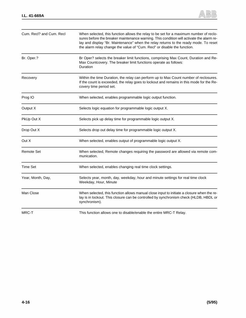
Cum. Recl? and Cum. Recl When selected, this function allows the relay to be set for a maximum number of reclo-sures before the breaker maintenance warning. This condition will activate the alarm re-lay and display “Br. Maintenance” when the relay returns to the ready mode. To resetthe alarm relay change the value of “Cum. Recl” or disable the function.
Br. Oper.? Br Oper? selects the breaker limit functions, comprising Max Count, Duration and Re-Max Countcovery. The breaker limit functions operate as follows:Duration
Recovery Within the time Duration, the relay can perform up to Max Count number of reclosures.If the count is exceeded, the relay goes to lockout and remains in this mode for the Re-covery time period set.
Prog IO When selected, enables programmable logic output function.
Output X Selects logic equation for programmable logic output X.
PkUp Out X Selects pick up delay time for programmable logic output X.
Drop Out X Selects drop out delay time for programmable logic output X.
Out X When selected, enables output of programmable logic output X.
Remote Set When selected, Remote changes requiring the password are allowed via remote com-munication.
Time Set When selected, enables changing real time clock settings.
Year, Month, Day, Selects year, month, day, weekday, hour and minute settings for real time clockWeekday, Hour, Minute
Man Close When selected, this function allows manual close input to initiate a closure when the re-lay is in lockout. This closure can be controlled by synchronism check (HLDB, HBDL orsynchronism).
MRC-T This function allows one to disable/enable the entire MRC-T Relay.

I.L. 41-669A
(5/95) 4-17
ADDITIONAL FUNCTIONS WITH THE SYNCH-CHECK OPTION
Sync Set? When selected, enables all synchronization, HBDL and HLDB relatedsettings.
VMax The voltage threshold above which the bus or line is considered “live”.
VMin The voltage threshold under which the bus or line is considered “dead”.
Sync Time The minimum time required for one of the selected conditions (HBDL, HLDB, SYNC) toallow reclosure to occur.
Sync Angle Selects the maximum angle for which Line and Bus are considered in synchronism.
Reclx HLDB When selected, permits a reclosure when the line is “live” and the bus is “dead”.(X being the reclosure number)
Reclx HBDL When selected, permits a reclosure when the bus is “live” and the line is “dead”.(X being the reclosure number)
Reclx Sync When selected, permits a reclosure when the synchronism condition is fulfilled(x being the reclosure number) (line “live”, bus “live” and the difference of angle is lower or equal to the Sync angle).
If Reclx (x=1,2,3 or 4), sync is set to “Yes” for the last reclosure, (see “Reclosures” set-ting) MRC-T will enter the Intermediate Lockout (“Int. Lo”) state, will display “Int. Lo” andthe Int. Lo alarm relay will be energized while waiting for synchronism. If synchronismis achieved before the “Reclx Wait” timer expires, MRC-T will display “Timing Sync”,then time out, reset and return to Ready State.
Reclx Wait This function is used to set a maximum waiting time for the condition for HLDB, HBDL or(x being the reclosure number) synchronism to occur. If the Recl x wait time expires, the reclosure goes to lockout. An
infinite Recl x wait time is selected by choosing “No Time Limit.”
Man HLDB When selected, permits a manual closure when the line is “live” and the bus is “dead”.
Man HBDL When selected, permits a manual closure when the bus is “live” and the line is “dead”.
Man SYNC When selected, permits a manual closure when the synchronism conditions is fulfilled.(Line “live”, bus “live” and the difference of angle is lower or equal to the Sync angle.)
Man Wait This function is used to set a maximum waiting time for the condition for HLDB, HBDLor synchronism to occur. If the manual wait time expires, the manual closure goes toLockout. An infinite wait time is selected by choosing “No Time Limit”.
*
*
*
*
*
*
* These features are available with out sync-check option, but will only respond to external “synccheck” signal input FT-17 & FT-20.

I.L. 41-669A
4-18 (5/95)
HARD WIRED FUNCTIONS DESCRIPTION
Drive to Lockout [DR LOCK] This is an optically isolated input. When present it will drive the relay to lockout from any-where in the sequence. The relay will stay in “LOCKOUT” until the drive to lockout inputis removed. Then the relay will continue the sequence before ending in the “READY”mode (after a reset in “LOCKOUT”).
Manual Close This is an optically isolated input, used for manual close Initiate
Hold This is optically isolated input. When present the reclosing relay “freezes”. All timing andall sequencing shall stop until the “HOLD” input is removed. It will then continue fromthe point at which action was suspended.
Sync Check This is an optically isolated input, used for external synchronism input.
Skip This is an optically isolated input, used for reclosure skip.
In-Progress This is an output relay with N.O. or N.C. contacts selectable through a jumper. This out-put is energized during the reclosing sequence and de-energized in “READY” and“LOCKOUT” modes.
Lockout This is an output relay with N.O. or N.C. contacts selectable through a jumper. This out-put is energized when the relay is in the “LOCKOUT” mode.
FAILED RECLOSE This is an output relay with N.O. or N.C. contacts selectable through a jumper. This out-put is energized when the relay is in the “FAILED RECLOSE” state.
52b This is an optically isolated input, used to determine breaker status
RI This is an optically isolated input, which when enabled can initiate a reclosuresequence.
RB This is an optically isolated input, which when enabled will block a reclosureinitiated by RI input.
ALARM This is an output relay with N.O. or N.C. contacts selectable through a jumper. This out-put is deenergized when the relay has self-tests error or loses power. It is energizedwhen the relay operates normally.
INT LO Alarm This is an output relay with N.O. or N.C. contacts selectable through a jumper. This out-put is energized when the relay is in intermediate lockout.
IN A/HLDB This is an optically isolated input, used for programmable I/O input A or switched syn-chronism HLDB.
IN B/HBDL This is an optically isolated input, used for programmable I/O input B or switched syn-chronism HBDL.
IN C/SYNC This is an optically isolated input, used for programmable I/O input C or switched syn-chronism SYNC.

I.L. 41-669A
(5/95) 4-19
IN D This is an optically isolated input, used for programmable I/O input D
OUT 1 This is an output relay with N.O. or N.C. contacts selectable through a jumper. Thisrelay is energized when the logic value of OUT1 calculated according to the logicequation 1 selected in the settings is true during the certain time selected usingthe pick up timer 1 setting.
OUT 2 This is an output relay with N.O. or N.C. contacts selectable through a jumper. Thisrelay is energized when the logic value of OUT 2 calculated according to the logicequation 2 selected in the settings is true during the certain time selected usingthe pick up timer 2 setting.
4. 9. COMMUNICATION PORT(S) USE
4.9.1 Introduction
MRC-T can be communicated with for target data, settings, etc., through the man-ma-chine interface (MMI), if supplied, or via one of the communication (comm.) ports.Comm. port communications, provides the user with more information than is avail-able with the MMI. For example, all 16 targets are available and more friendly user in-terface for settings can be accessed (all settings are displayed on a single screen on theuser’s PC). This section will provide the details of the comm. port options, personalcomputer requirements, connecting cables and all information necessary to commu-nicate with and extract data from the relay. Additional communications details arecontained in I.L. 40-603, “RCP Remote Communication Program”.
4.9.2 Communication Port Options
MRC-T is supplied with a rear communications port. If the network interface is notspecified, a RS-232C [hardware standard] communications port is supplied. Networkinterface comm. port option allows the connection of the relay with many other devicesto a 2-wire network. A detailed discussion of networking capabilities can be found inAD 40-600, “Substation Control and Communications Application Guide”.
RS-232C, rear comm. ports are of the removable, Product Operated Network Interface(PONI) type and are available in two styles. One is identified by a 25 pin [DB-25S] fe-male connector, it is usually black in color, and has a single data comm. rate of 1200bps. The second style is identified by a 9 pin [DB-9P] male connector and externallyaccessible dip switches (next to the connector) for setting the comm. data rate. Thisport option is always black in color, can be set for speeds of 300, 1200, 2400, 4800,or 9600 bps and offers an option for IRIG-B time clock, synchronization input.
Front communications is another comm. port option. The front panel RS-232C com-munications port, is supplied with a 9 pin [DB-9S] female connector and can be con-figured for 300, 1200, 2400, 4800, 9600 or 19200 bps. Data comm. rate choice ismade by dip switch settings which will be discussed later in this chapter.
4.9.3 Personal Computer Requirements
Communication with the relay requires the use of Remote Communication Program(RCP) regardless of the comm. port option. RCP is supplied by ABB Relay Division andis run on a personal computer (PC).

I.L. 41-669A
4-20 (5/95)
To run the program requires an IBM AT, PS/2 PC (or greater) true compatible with aminimum of 640 kilobytes of RAM, 1 hard disk drive, a RS-232C comm. port and avideo graphics adapter card. The PC must be running Version 3.3, or higher, MS-DOS.
4.9.4 Connecting Cables
With each comm. port option the connecting cable requirement can be different. Also,connecting directly to a PC or connecting to a modem, for remote communication, af-fects the connecting cable requirements. Table 4-9 provides a summary of plug pin as-signments, pins required and cable connectors.
Some terminology will be defined to aid the user in understanding cable requirementsin Table 4-9. Reference is often made to the “RS-232C” standard, for data communi-cation. The RS-232C standard describes mechanical, electrical, and functional char-acteristics. This standard is published by the Electronics Industry Association, (EIA)and use of the standard is voluntary but widely accepted for electronic data transfer.ABB relay communications follows the RS-232C standard for non-network data com-munication.
Although the RS-232C standard does not specify a connector shape, the most com-monly used is the “D” shape connector. As stated in Section 4.9.2 above, all ABB relaycommunication (except network communications) connectors are of the “D” shape(such as DB-25S).
Data Communication devices are categorized as either Data Terminal Equipment[DTE] or Data Communication Equipment [DCE]. A DTE is any digital device thattransmits and/or receives data and uses communications equipment for the datatransfer. DCEs are connected to a communication line (usually a telephone line) for
TABLE 4-9COMMUNICATIONS CABLE REQUIREMENTS
Connection Type(From RelayComm Port)
Cable(Straight = nonull modem)
Pins Req’d.(All pins not
required)
Cable Connectors(Comm Port to PC
or Modem)
Notes
DB-25S, RS-232Cconnected to PC*
Straight 2,3,7 To port: 25 pin DTETo PC: 9 or 25 pin DCE
DB-25S RS-232Cconnected to Modem
Null Modem 2,3,7 To port: 25 pin DTETo Modem: 25 pin DTE
DB-9P, RS-232C con-nected to PC*
Null Modem 2,3,5 To port: 9 pin DCETo PC: 9 or 25 pin DCE
See IL 40-610for settings
DB-9P, RS-232Cconnected to Modem*
Straight 2,3,5 To port: 9 pin DCETo Modem: 25 pin DTE
See IL 40-610for settings
DB-9S, RS-232Cconnected to PC*
Straight 2,3,5,7,8 To port: 9 pin DTETo PC: 9 or 25 pin DCE
See Table 4-10for settings
DB-9S, RS-232Cconnected to Modem
Null Modem 2,3,5,7,8 To port: 9 pin DTETo Modem: 25 pin DTE
See Table 4-10for settings
I.L. 41-669A
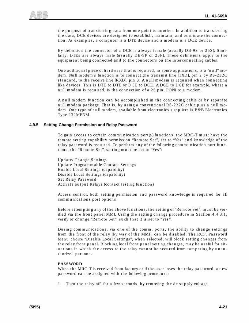
(5/95) 4-21
the purpose of transferring data from one point to another. In addition to transferringthe data, DCE devices are designed to establish, maintain, and terminate the connec-tion. As examples, a computer is a DTE device and a modem is a DCE device.
By definition the connector of a DCE is always female (usually DB-9S or 25S). Simi-larly, DTEs are always male (usually DB-9P or 25P). These definitions apply to theequipment being connected and to the connectors on the interconnecting cables.
One additional piece of hardware that is required, in some applications, is a “null” mo-dem. Null modem’s function is to connect the transmit line [TXD], pin 2 by RS-232Cstandard, to the receive line [RXD], pin 3. A null modem is required when connectinglike devices. This is DTE to DTE or DCE to DCE. A DCE to DCE for example, where anull modem is required, is the connection of a 25 pin, PONI to a modem.
A null modem function can be accomplished in the connecting cable or by separatenull modem package. That is, by using a conventional RS-232C cable plus a null mo-dem. One type of null modem, available from electronics suppliers is B&B ElectronicsType 232MFNM.
4.9.5 Setting Change Permission and Relay Password
To gain access to certain communication port(s) functions, the MRC-T must have theremote setting capability permission “Remote Set”, set to “Yes” and knowledge of therelay password is required. To perform any of the following communication port func-tions, the “Remote Set”, setting must be set to “Yes”:
Update/Change SettingsUpdate Programmable Contact SettingsEnable Local Settings (capability)Disable Local Settings (capability)Set Relay PasswordActivate output Relays (contact testing function)
Access control, both setting permission and password knowledge is required for allcommunications port options.
Before attempting any of the above functions, the setting of “Remote Set”, must be ver-ified via the front panel MMI. Using the setting change procedure in Section 4.4.3.1,verify or change “Remote Set”, such that it is set to “Yes”.
During communications, via one of the comm. ports, the ability to change settingsfrom the front of the relay (by way of the MMI), can be disabled. The RCP, PasswordMenu choice “Disable Local Settings”, when selected, will block setting changes fromthe relay front panel. Blocking local front panel setting changes, may be useful for sit-uations in which the access to the relay cannot be secured from tampering by unau-thorized persons.
PASSWORD:When the MRC-T is received from factory or if the user loses the relay password, a newpassword can be assigned with the following procedure:
1. Turn the relay off, for a few seconds, by removing the dc supply voltage.

I.L. 41-669A
4-22 (5/95)
2. Re-apply dc supply voltage to re-energize the relay.
3. Using RCP, perform the Password Menu choice “Set Relay Password”. Use theword “password” for the “current relay password” and then select a new password.
The password setting procedure must be completed within 15 minutes of ener-gizing the relay.
4.9.6 Setting up the Front Communications Port
The front RS-232C comm. port, on the relay, consists of a printed circuit board thatplugs flat into the rear of the microprocessor module. On the front panel, of the relay,is the 9-pin [DB-9S] DCE connector with it’s associated enabling push-button, next tothe connector. As described above, communications with the relay requires a serial ca-ble from the comm. port to the communicating device (usually a local PC).
The front comm port data rate must match the comm. port data rate of the device con-nected to the port. This data rate is set when configuring communications on the com-municating device. If the communicating device is a PC, the data rate is set by RCPeither when setting up RCP or by changing settings while running RCP.
To set the data rate on the front comm. port the five dip switch poles of switch S1 (seeFigure 1-13) must be set according to Table 4-10. When the relay is viewed from thefront, (front cover removed) the switch S1 is located on the right side of the front panelnear the top (on the top of the front panel and on the left for horizontally mounted re-lays). Only the first three poles, #1, #2 and #3, of the switch, are used to set the com-munications bit rate. Refer to Table 4-10 for the correct position of the switch poles.Note that settings 110 and 111 result in the default bit rate of 1200 bps.
4.9.6.1 Front Port Operations
When the communication hardware is in place, communicating with the front requirespressing of the push-button beside the connector in order to switch from the rear tofront port. There after, the communication will remain with the front until no datatransfer has taken place for two minutes. The push-button can be pressed again totoggle from front to rear or reverse.
RCP operations are identical for front and rear communication [RS-232 or INCOM]. Itis possible that the communication is unsuccessful the first time after a relay power-up or switching between protection and recloser. In this case, a second attempt shouldprove successful.
4.9.6.2 Troubleshooting
In the event the communication remains unsuccessful, first make sure that the frontcommunication push-button has been depressed, the relay is powered and the con-nection is good.

I.L. 41-669A
(5/95) 4-23
For further test, remove the front cover and check that the bit rate on the communi-cation board (dip switches; refer to Table 4-10) is set to correspond to the one dis-played at the bottom right of the RCP screen
If after these verifications the problem remains, try to remove the power from the relayand apply it again. If the communication still fails (several attempts), the communica-tion board may need to be serviced.
TABLE 4-10COMMUNICATIONS PORT
DIP SWITCH SETTINGS(See Figure 1-13 for location of dip switch S1)
Dip Switch
Bps#1 #2 #3
00001111
00110011
01010101
30012002400480096001920012001200
Logic 1 is towards printed circuit board
Dip position 4 & 5 are not used

I.L. 41-669A
4-24 (5/95)
Figure 4-1. MRC-T Backplate
1357D57


I.L. 41-669A
4-26(5/95)
sub 11617C05
Figure 4-3. MRC-T System External Connection

I.L. 41-669A
(5/95)4-27
1617C07
Sub 1
Sheet 1 of 3Figure 4-4a MRC-T System Connections

I.L. 41-669A
4-28(5/95)
1617C07Sub 1
Sheet 2 of 3Figure 4-4b MRC-T System Connections

I.L. 41-669A
(5/95)4-29
1617C07Sub 1
Sheet 3 of 3Figure 4-4c MRC-T System Connections

I.L. 41-669A
(5/95) A-1
THIS PROCEDURE PROVIDES AN IN DEPTH TEST OF MRC-T FUNCTIONALITY. IT IS NOTREQUIRED TO PERFORM THE ENGINEERING EVALUATION TEST FOR ACCEPTANCE TEST-ING. FOR ACCEPTANCE TEST, SEE APPENDIX B. IF YOU HAVE A RELAY WITHOUT SYNC-CHECK OPTION ONLY COMPLETE SECTIONS 1 & 2.
APPENDIX A. ENGINEERING EVALUATION TEST
1 RECLOSER W/O SYNC-CHECK OPTION
Check that all jumpers of the output relays are in the N.O. (Normally Open) positionexcept the Alarm Relay (J1 Bottom I/O module, Figure 1-8) which should be in theN.C. (Normally Closed) position. Check that all voltage jumpers are set to dc and ratedvoltage. Hereafter the rated dc voltage will be referred to as dc. (See Figures 1-8through 1-11 for jumper locations.)
1.1 FRONT PANEL CHECK
STEP 1: Power Up Initialization
Connect dc to FT-9 (-), FT-20 (-) and FT-10 (+) and turn on power. The display willshow “LOCKOUT” condition and the LOCKOUT LED will be on. After the reset timertimes out, the LCD on the MRC-T should change from “Lockout Reset” to “READYMRC-T V1.xx” where “xx” is the last two digits of the installed firmware version. TheReclosing-in-Service LED and Alarm Relay (FT-3 & FT-4 contact-open) should be en-ergized to indicate successful self-check on power up and the LOCKOUT LED will turnoff.
STEP 2: Default Settings Check
Press the select push-button to access the settings mode. Scroll through the settingsby pressing raise or lower to verify that settings are as in Table 4-5 “Factory Default”.Change settings if necessary (see Installation & Operations section for details). Pressselect until the test mode appears. The “Status” display should read “OK”. Return therelay to the Ready Mode by either pressing the Select push-button or the Reset push-button once.
1.2 RECLOSE BREAKER CHECK
STEP 1: 52b RECLOSE INITIATION FUNCTION
Momentarily apply (+)dc to the 52b terminal (FT-8) and remove. The relay will start areclose sequence with RECL1 Dead Time. While the MRC-T is timing the Recl1 DeadTime, the LCD will display the timing “count down” and the In-Progress relay (FT-15& FT-11) will energize. Once the RECL1 timer times out the Close Relay (FT-1 & FT-2)will energize to reclose the breaker. After the Reset Time Delay times out, the relay willreturn to ready and the In-Progress relay will drop out. The In-Progress relay will beenergized during all relay operations other than READY and LOCKOUT modes.

I.L. 41-669A
A-2 (5/95)
STEP 2: FAILED RECLOSE AND MANUAL CLOSE
FAILED RECLOSE
Change the MRC-T “MAN CLOSE” setting to “YES”. Press the select push-button asnecessary to return the MRC-T to the “READY” mode. Apply dc (+) to the 52b terminal(FT-8). While the MRC-T is timing, the Recl1 Dead Time, the LCD will display the tim-ing “count down” and the In-Progress relay (FT-15 & FT-11) will energize. Once theRECL1 timer times out, the MRC-T will attempt to issue a reclose however, since the52b contact input is still present, the Reclose Fail timer begins timing. Once the Re-close Fail timer has timed out, the “FAILED RECLOSE” & “LOCKOUT” LED’s willlight. The close and in progress contacts will drop out at this point in time. Thedisplay on the MRC-T should show “LOCKOUT, Failed Reclose”. Remove the dc fromterminal FT-8.
MANUAL CLOSE
Apply dc (+) to the Manual Close terminal (FT-16). The “LOCKOUT” reset timer will be-gin timing. After the LOCKOUT reset timer times out, the “LOCKOUT” LED on theMRC-T front panel will go out. Remove the dc from terminal FT-16. The “FAILED RE-CLOSE” LED on MRC-T front panel will remain lit until reset push-button on MRC-Tfront panel is pushed. Push reset push-button and “FAILED RECLOSE” LED shouldgo out.
STEP 3: RECLOSE INITIATE AND RECLOSE BLOCK
RECLOSE INITIATE FUNCTION
Change the “Recl1” setting to “RI Only” and verify the “Recl1 RB” setting is set to “No”.Press the select push-button as necessary to return the MRC-T to the “READY” mode.Momentarily apply dc (+) to the 52b terminal (FT-8). The recloser should not begin tim-ing since the 52b contact should have no effect on reclose initiation with the currenttest settings.
Momentarily apply dc (+) to the “Reclosure Initiate” terminal (FT-5). MRC-T will starta reclose sequence with the “Recl1 Dead Time”. While the MRC-T is timing the Recl1Dead Time, the LCD will display the timing “count down” and the In-Progress relay(FT-15 & FT-11) will energize. After the RECL1 dead timer times out the Close contact(FT-1 & FT-2) will close. the reset timer should then begin timing out. Once the resettimer has timed out, the MRC-T should return to the “READY” mode.
RECLOSE BLOCK FUNCTION
Change the “Recl1 RB” setting to “Yes”. Press the select push-button as necessary toreturn the MRC-T to the “READY” mode. Apply dc (+) to the “Reclosure Block” terminal(FT-6). Momentarily apply dc (+) to the “Reclosure Initiate” terminal (FT-5). The MRC-T should skip “Recl1 Dead Time” (due to the Reclosure block input), jump to “Recl2”,reclose after the Recl2 dead time expires, reset, and return to “READY” mode. ChangeMRC-T settings as follows: “Recl1 RB” setting to “NO”, “Recl1” setting to “52b Only”.
STEP 4: INTERMEDIATE LOCKOUT (Int LO)ALARM EXTERNAL (Ext) SYNC-CHECK
I.L. 41-669A
A-3 (5/95)
Change the MRC-T synchronism functions enable setting “Sync Set?” to “Yes”, the“Recl4 Sync” setting to “Yes”, and the “Recl4 Wait” setting to “No time limit”. Press se-lect push-button on MRC-T front panel as necessary to return to the “READY” mode.Momentarily apply dc (+) to the 52b terminal (FT-8). MRC-T will start a reclose se-quence with the “Recl1 Dead Time”. While the MRC-T is timing the Recl1 Dead Time,the LCD will display the timing “count down” and the In-Progress relay (FT-15 & FT-11) will energize. After the RECL1 dead timer times out, and while the reset timer isin the process of timing out, again momentarily apply dc (+) to the 52b terminal (FT-8), which will now start the Recl2 dead timer. Repeat this process until the Recl4 deadtimer begins timing out. Once the Recl4 timer times out, the “WAIT BUS/LINE”, “NoTime Limit” display will appear on the MRC-T front panel and the “INT LO” alarm con-tacts (FT-11 & FT-12 will close. Momentarily apply dc (+) to the Sync-Check input ter-minal (FT-17). The MRC-T display will change to “TIMING SYNC” then time-out after2 seconds, reset, and return to “READY” mode. The Int LO alarm should drop out oncethe MRC-T returns to the “READY” mode. Change MRC-T settings as follows: “Recl4Sync” setting to “NO”.
STEP 5: SKIP INPUT
Momentarily apply 52b signal, the relay will begin a reclose sequence with RECL1dead time. During the dead time momentarily apply dc to the SKIP Input (FT-19). Thiswill cause the relay to skip to RECL2 dead time without attempting the RECL1 closure.The relay then times out, energizes the close relay, resets and returns to “READY”mode.
2 INPUT OPTO-COUPLER CHECK
STEP 1: DRIVE TO LOCKOUT
(For a complete input circuit integrity test, see MMI Modes of Operation Part Ein Sec-tion 4.4.3.1).
Apply dc to the drive to LOCKOUT input (FT-7). The relay will display “LOCKOUT”DRIVE TO LOCKOUT”. The LOCKOUT LED and relay will be energized. Remove dcvoltage from the input and the relay will return to “READY” mode after the Timer Resettimes out.
STEP 2: HOLD
Change the “HOLD” setting to “YES”. Apply rated dc to the drive to LOCKOUT inputthen remove it. During the reset time apply dc to the hold input (FT-18). The reset tim-er will freeze at that time and only resume when the voltage is removed. Remove thevoltage and the relay will return to the ready state after the remaining reset time, timesout.
STEP 3: PROGRAMMABLE INPUTS/OUTPUTS
Change “PROG IO setting” to “YES” and the output 2 relay (TB1-7 & TB1-8) will ener-gize 2 seconds after the “VALUE ENTERED” message is displayed. Then press the re-set button to return to the ready mode. Apply dc to the programmable input A [TB2-1(+) & TB2-2(-)] the output 2 relay will drop out after 1 second. (For a complete inputcircuit integrity test, see MMI Modes of Operation parts in Section 4).

I.L. 41-669A
A-4 (5/95)
Apply dc to the following: Input B [TB2-3(+) & TB2-4(-), Input C [TB2-5(+) & TB2-6(-),and Input D [TB2-7(+) & TB2-8(-)]. Output 1 [TB1-5(+) & TB1-6(-), will energize 2 sec-onds after the last input is connected. Remove all programmable input voltages, out-put 1 will dropout 1 second after the first input is removed. Return “PROG IO” and“HOLD” settings to “NO”.
This completes the Acceptance test for relays without Sync-Check.
3 SYNC-CHECK OPTION TESTS
A dual variable voltage source is required, the source must provide 70 Vac (or 120 Vacfor 120 volt relay), with adjustable phase angle. Check R7 on the Microcontroller mod-ule, if present the input frequency is 60 Hz and 50 Hz if removed. Connect the VBUSto (TB1-1 & TB1 -2) and the VLINE to (TB1-3 & TB1-4). change “SYNC-SET” to “YES”.
STEP 1: SYNCHRONISM CHECK
Apply rated ac voltage to VBUS and VLINE with the phase angle difference of 18 de-grees. The synchronism LED should be on. Increase the phase angle to 22 degrees andthe synchronism LED will then turn off.
STEP 2: METERING CHECK
Scroll the display to the test mode then push the lower button to verify that “BUS-LINE” “ANGLE”, “V LINE” and “V BUS” are reading the correct values.
STEP 3: HBDL & HLDB LED CHECK
Reduce the line voltage to 10 Vac and check that the HBDL LED is on. Increase linevoltage to 55 Vac and reduce BUS Voltage to 10 volts. This should cause the “HLDB”LED to turn on and the “HBDL” LED to turn off.
This completes the SYNC-Check Tests for the MRC-T Relay.

I.L. 41-669A
(5/95) B-1
1. RECLOSER W/O SYNC-CHECK OPTION
Before beginning the Acceptance Test verify that all jumpers are set to dc and forthe correct, rated voltage (see Appendix A, Section 1.) See Figures 1-8 through 1-11for jumper locations and designations. Connect rated dc voltage to FT-9 (-), FT-20(-) and FT-10 (+).
STEP 1: FRONT PANEL CHECK
Turn on the dc power to the relay. The display will show “LOCKOUT” condition and theLOCKOUT LED will turn on. The relay will then reset after the reset timer times outand return to the Ready Mode, display the software version and the LOCKOUT LED willturn off. The Reclosing-in-Service LED should light and Alarm Relay (FT-3 & FT-4)should be energized to indicate successful self check on power-up.
STEP 2: OUTPUT RELAY AND STATUS CHECK
Press the Select push-button to access the Test mode. Check that the “STATUS” dis-play reads “OK”. Press the RAISE push-button to access Test for Output relays andLEDs (See Section 4.4.3.1 part Efor details). For each Output relay or LED, press theEnter push-button to determine that it energizes, except the Alarm relay which will de-energize. Return the relay to the Ready mode by pressing the Reset push-button.
2. SYNC-CHECK OPTION TESTS
Remove front faceplate and check for the presence or absence of R7 on the Microcon-troller module, the input frequency is 60 Hz if present, 50 Hz if absent. Change “SYNCSET” to “YES”.
STEP: 1 SYNCHRONISM AND METERING CHECK
Apply a single 70 Vac source to both VBUS (TB1-1 & TB1-2) and VLINE (TB1-3 & TB1-4). at the rated frequency. The synchronism LED should be on. Scroll the display toTest Mode then push the “Lower” button to verify that “BUS-LINE” “ANGLE”, “V LINE”and “V BUS” are reading the correct values.
STEP 2: LED CHECK
While in the Test Mode, press the “lower” push-button until the “BUS/LINE” “LEDs” isdisplayed. Press the Enter push-button to turn on the “SYNCHRONISM”, “HBDL” and“HLDB” LEDs.
This completes the Acceptance Test. Return all settings to values in Table 4-3 or to de-sired service settings.
APPENDIX B. ACCEPTANCE TESTS
THIS IS A BASIC PROCEDURE TO DETERMINE IF A PARTICULAR MRC-T UNIT IS OPERATINGCORRECTLY. MORE EXTENSIVE TESTS FOR OUTPUTS AND INPUTS CAN BE PERFORMED IFDESIRED BY FOLLOWING THE ENGINEERING EVALUATION TESTS IN APPENDIX A. IF YOUHAVE A RELAY WITHOUT SYNC-CHECK OPTION COMPLETE ONLY SECTION 1.

I.L. 41-669A
(5/95) C-1
It is NOT RECOMMENDED TO PERFORM any type of invasive
periodic maintenance test (requiring relay disassembly).
Appendix C. PERIODIC MAINTENANCE TESTS
1. PERIODIC MAINTENANCE TESTS
1. 1. Using Data Communication Port
• Read Metering Values
• Read Diagnostic Information
• Monitor Relay Failure Indication
• Remotely test Output Relay (Trip, Close, etc.)
• Check for Failure Alarm via annunciator or network
1. 2. Using Man-Machine Interface
• Use the front display, and push-buttons to manually perform the tests described inSection 1.1 above.
1. 3. Routine Visual Inspection
With the exception of routine visual inspection, the MRC-T relay assembly should bemaintenance free for one year. A program of routine visual inspection should include:
• Condition of cabinet or other housing
• Tightness of mounting hardware
• Proper seating of subassemblies
• Condition of external wiring
• Appearance of printed circuit boards and components
• Signs of overheating in equipment
1. 4. Perform the Acceptance Test
Performing this test is optional if all other test results are acceptable.
NOTE

I.L. 41-669A
(5/95) D-1
The MRC-T has been calibrated at the factory; adjustments by the customer are notrequired. The following information is for reference only.
The power supply trim pot P9 is to adjust the +12 Vdc A/D reference. The voltage canbe measured between TP1 and inductor L2. Clockwise rotation of the pot screw willdecrease the reference voltage.
The display module option has a trim pot R6 which allows slight adjustment of theviewing angle. This adjustment can be made without removing the front panel.
CAUTION
Excessive adjustment of this pot could cause the display to go blank.
Appendix D. CALIBRATION

(5/95) E - 1
I.L. 41-669A
Numerics
52b - - - - - - - - - - - - - - - - - - - - - - - - - - - - - -1-2, 4-2, 4-5, 4-6, 4-7, 4-8, 4-10, 4-12, 4-14, 4-15, 4-16, A-1, A-2
A
ALARM - - - - - - - - - - - - - - - - - - - - - - - - - - - - - - - - - - - - - - - - - - - - - - - - - - - - - - - - - - - - - - - - - - - 4-7, 4-18ALARM RELAY - - - - - - - - - - - - - - - - - - - - - - - - - - - - - - - - - - - - - - - - - - - - - - - - - - - - 4-1, 4-11, 4-16, 4-17
B
BUS - - - - - - - - - - - - - - - - - - - - - - - - - - - - - - - - - - - - - - - - - - - - - - - - - - - - - - - - - - - - - - - - - - - - - - - - - A-4BUS-LINE - - - - - - - - - - - - - - - - - - - - - - - - - - - - - - - - - - - - - - - - - - - - - - - - - - - - - - - - - - - - - - - - - - - - A-4
C
CLOSE RELAY - - - - - - - - - - - - - - - - - - - - - - - - - - - - - - - - - - - - - - - - - - - - - - - - - - - - - - - - - - - - - 4-1, 4-10
D
DRIVE TO LOCKOUT - - - - - - - - - - - - - - - - - - - - - - - - - - - - - - - - - - - - 3-1, 4-1, 4-10, 4-11, 4-12, 4-18, A-3
E
EEPROM - - - - - - - - - - - - - - - - - - - - - - - - - - - - - - - - - - - - - - - - - - - - - - - - - - - - - - - - - - - - - - - - - 1-3, 4-11EPROM - - - - - - - - - - - - - - - - - - - - - - - - - - - - - - - - - - - - - - - - - - - - - - - - - - - - - - - - - - - - - - - - - - 1-3, 4-11
F
FAILED - - - - - - - - - - - - - - - - - - - - - - - - - - - - - - - - - - - - - - - - - - - - - - - - - - - - - - - - - - - - - - - - - - - 4-11,A-1FAILED RECLOSE - - - - - - - - - - - - - - - - - - - - - - - - - - - - - - - - - - - - - - - 1-2, 4-2, 4-3, 4-10, 4-15, 4-18, A-1
H
HBDL - - - - - - - - - -1-2, 3-1, 4-2, 4-3, 4-4, 4-5, 4-6, 4-7, 4-9, 4-11, 4-12, 4-13, 4-14, 4-16, 4-17, 4-18, A-4, B-1HLDB - - - - - - - - - -1-2, 3-1, 4-2, 4-3, 4-4, 4-5, 4-6, 4-7, 4-9, 4-11, 4-12, 4-13, 4-14, 4-16, 4-17, 4-18, A-4, B-1HOLD - - - - - - - - - - - - - - - - - - - - - - - - - - - - - - - - - - - - - - - - - - - - - - - - -3-1, 4-2, 4-7, 4-10, 4-15, 4-17, 4-18
I
IN PROG - - - - - - - - - - - - - - - - - - - - - - - - - - - - - - - - - - - - - - - - - - - - - - - - - - - - - - - - - - - - - - - - - - - - - 4-2IN A - - - - - - - - - - - - - - - - - - - - - - - - - - - - - - - - - - - - - - - - - - - - - - - - - - - - - - - - - - - - 4-2, 4-14, 4-10, 4-18IN B - - - - - - - - - - - - - - - - - - - - - - - - - - - - - - - - - - - - - - - - - - - - - - - - - - - - - - - - - - - - 4-2, 4-14, 4-10, 4-18IN C - - - - - - - - - - - - - - - - - - - - - - - - - - - - - - - - - - - - - - - - - - - - - - - - - - - - - - - - - - - - 4-2, 4-14, 4-10, 4-18INCOM - - - - - - - - - - - - - - - - - - - - - - - - - - - - - - - - - - - - - - - - - - - - - - - - - - - - - -1-2, 1-3, 2-1, 3-2, 4-2, 4-22IN D - - - - - - - - - - - - - - - - - - - - - - - - - - - - - - - - - - - - - - - - - - - - - - - - - - - - - - - - - - - - 4-2, 4-14, 4-10, 4-19INT - - - - - - - - - - - - - - - - - - - - - - - - - - - - - - - - - - - - - - - - - - - - - - - - - - - - - - - - - - - - - - - - - - - - - - - - - - A-2INT LO ALARM - - - - - - - - - - - - - - - - - - - - - - - - - - - - - - - - - - - - - - - - - - - - - - - - - - - - - - - - - 4-2, 4-18, A-2
L
LCD - - - - - - - - - - - - - - - - - - - - - - - - - - - - - - - - - - - - - - - - - - - - - - - - - - - - - - - - 1-2, 1-3, 3-2, 4-2, A-1, A-2LED - - - - - - - - - - - - - - - - - - - - - - - - - - - - - - - - - - - - -1-2, 1-3, 4-2, 4-3, 4-10, 4-11, 4-15, A-1, A-2, A-3, A-4LOCKOUT - - - - - - - - - - - -1-2, 3-1, 4-2, 4-3, 4-9, 4-10, 4-11, 4-12, 4-15, 4-16, 4-17, 4-18, A-1, A-2, A-3, B-1LOCKOUT LED - - - - - - - - - - - - - - - - - - - - - - - - - - - - - - - - - - - - - - - - - - - - - - - - - - - 4-3, A-1, A-2, A-3, B-1

E -2 (5/95)
PRELIMINARY I.L. 41-669
M
Man Close - - - - - - - - - - - - - - - - - - - - - - - - - - - - - - - - - - - - - - - - - - - - - - - - - - - - - - - - - - - - -4-2, 4-9, 4-16
MAN SYNC - - - - - - - - - - - - - - - - - - - - - - - - - - - - - - - - - - - - - - - - - - - - - - - - - - - - - - - - - - - - - - - - 4-9, 4-17
MULTI-SHOT RECLOSING - - - - - - - - - - - - - - - - - - - - - - - - - - - - - - - - - - - - - - - - - - - - - - - - - - - - - - - - 3-2
O
OUT 1 - - - - - - - - - - - - - - - - - - - - - - - - - - - - - - - - - - - - - - - - - - - - - - - - - - - - - - - - - - - - 4-2, 4-8, 4-13, 4-19
OUT 2 - - - - - - - - - - - - - - - - - - - - - - - - - - - - - - - - - - - - - - - - - - - - - - - - - - - - - - - - - - - - 4-2, 4-8, 4-13, 4-19
P
PONI - - - - - - - - - - - - - - - - - - - - - - - - - - - - - - - - - - - - - - - - - - - - - - - - - - - - - - -1-2, 1-3, 2-1, 4-1, 4-3, 4-18
PROG IO - - - - - - - - - - - - - - - - - - - - - - - - - - - - - - - - - - - - - - - - - - - - - - - - - - - - - - - - - - 4-6, 4-9, 4-12, A-2
R
RB - - - - - - - - - - - - - - - - - - - - - - - - - - - - - - - - - - - - - - - - - - - - - - - - - - - - 4-2, 4-5, 4-6, 4-7, 4-15, 4-18, A-1
RCP - - - - - - - - - - - - - - - - - - - - - - - - - - - - - - - - - - - - - - - - - - - - - - - - - - - - - - - - - - - -4-19, 4-21, 4-22, 4-23
READY - - - - - - - - - - - - - - - - - - - - - - - - - - - - - - - - - - - - - - - - - - - - - - - - -3-1, 4-2, 4-3, 4-4, 4-11, 4-12, 4-14
RECL - - - - - - - - - - - - - - - - - - - - - - - - - - - - - - - - - - - - - - - - - - 4-4, 4-5, 4-6, 4-7, 4-9, 4-14, 4-15, 4-16, 4-18
RECL1 - - - - - - - - - - - - - - - - - - - - - - - - - - - - - - - - - - - - - - - - - - - - - - - - - - - - - - - - - - - - 4-5, 4-14, A-1, A-2
RECL2 - - - - - - - - - - - - - - - - - - - - - - - - - - - - - - - - - - - - - - - - - - - - - - - - - - - - - - - - - - - - - - - 4-6, 4-14, A-2
RECL3 - - - - - - - - - - - - - - - - - - - - - - - - - - - - - - - - - - - - - - - - - - - - - - - - - - - - - - - - - - - - - - - - - - - - - - - 4-6
RECL4 - - - - - - - - - - - - - - - - - - - - - - - - - - - - - - - - - - - - - - - - - - - - - - - - - - - - - - - - - - - - - - - - - - - -4-7, A-2
RI - - - - - - - - - - - - - - - - - - - - - - - - - - - - - - - - - - - - - - - - - - - - - 1-2, 4-5, 4-6, 4-7, 4-12, 4-14, 4-15, 4-18, A-1
S
SKIP - - - - - - - - - - - - - - - - - - - - - - - - - - - - - - - - - - - - - - - - - - - - - - - - - - - - - - - - - 3-1, 4-2, 4-4, 4-10, 4-18
SYNC - - - - - - - - - - - - - - - - - - - - - - - - - - - - - - - - - - - - - - 1-2, 4-5, 4-6, 4-7, 4-9, 4-10, 4-12, 4-13, 4-14, 4-17
SYNC ANGLE - - - - - - - - - - - - - - - - - - - - - - - - - - - - - - - - - - - - - - - - - - - - - - - - - - - - - - - - - - - - - - - - - 4-17
SYNC CHECK - - - - - - - - - - - - - - - - - - - - - - - - - - - - - - - - - - - - - - - - - - - - - - - - - 4-2, 4-10, 4-17, 4-18, A-4
SYNC SET - - - - - - - - - - - - - - - - - - - - - - - - - - - - - - - - - - - - - - - -4-3, 4-4, 4-5, 4-6, 4-7, 4-13, 4-17, A-4, B-1
SYNC TIME - - - - - - - - - - - - - - - - - - - - - - - - - - - - - - - - - - - - - - - - - - - - - - - - - - - - - - - - - - -4-5, 4-14, 4-17
SYNCHRONISM - - - - - - - - - - - - - - - - - 1-1, 1-2,4-2, 4-3, 4-5, 4-6, 4-7, 4-9, 4-12, 4-13, 4-16, 4-17, 4-18, B-1
T
TIMING SYNC - - - - - - - - - - - - - - - - - - - - - - - - - - - - - - - - - - - - - - - - - - - - - - - - - - - - - - - - - - - - -4-17, A-2
V
VBUS - - - - - - - - - - - - - - - - - - - - - - - - - - - - - - - - - - - - - - - - - - - - - - - - - - - - - - - - - - - - - - - - - - - - -4-2, A-2
VLINE - - - - - - - - - - - - - - - - - - - - - - - - - - - - - - - - - - - - - - - - - - - - - - - - - - - - - - - - - - - - - - - - - - - - - - - 4-2
VMax - - - - - - - - - - - - - - - - - - - - - - - - - - - - - - - - - - - - - - - - - - - - - - - - - - - - - - - - - - - - - - - - -4-4, 4-5, 4-17
VMin - - - - - - - - - - - - - - - - - - - - - - - - - - - - - - - - - - - - - - - - - - - - - - - - - - - - - - - - - - - - 4-4, 4-5, 4-13, 4-17