illinois disaster recovery program housing repair
TRANSCRIPT

Invitation for Bid (IFB)
Illinois Disaster Recovery Program
Housing Repair/ Rehabilitation and Reconstruction Program
Project Number # 352003.5
Proposal Due Date: December 18, 2013
Proposal Due Time: 2:00 PM

ILLINOIS DISASTER RECOVERY PROGRAM
HOMEOWNER REPAIR/REHABILITATION PROGRAM
TABLE OF CONTENTS
The items below represent components which comprise this Invitation for Bid for Construction Services (this “IFB”). PART I: Instructions to Bidders PART II: General Construction Matters PART III: General Conditions PART IV: Rules and Regulations Specific to CDBG Funded Projects PART V: Bid Form
Attachment V-A Contractor Information with Schedules Schedule OM.A Company Owners Schedule OM.B Management Personnel Schedule F.1 Profit/Loss Statement Schedule F.8 Credit References Schedule EXP.1 Similar Project Experience Schedule EXP.2 Terminations Schedule SUB.1 Subcontractor Workforce Attachment V-B Nepotism Statement Attachment V-C Non-Collusion Statement Attachment V-D Drug-Free Workplace Act
PART VI: Work Write-Ups PART VII: IDRP Minimum Housing Rehabilitation Standards PART VIII: IDRP Contractor Specifications and Performance Manual PART IX: Bi-Party Rehabilitation Contract PART X: Contractor Forms Used During Construction
Attachment X-A Payment Bond Form Attachment X-B Performance Bond Form Attachment X-C Lead Based Paint Notification of Abatement and Demolition
Clearance Attachment X-D Not Used Attachment X-E Unconditional Waiver and Release of Lien Rights by
Subcontractor
IDRP Program Table of Contents TOC - 1

Attachment X-F Conditional Waiver and Release of Lien Rights by Subcontractor
Attachment X-G Notice to Proceed Attachment X-H Certificate of Commencement Attachment X-I Change Order Request Form Attachment X-J Certificate of Completion Attachment X-K Work Approval and Warranty
IDRP Program Table of Contents TOC - 2

PART I. INSTRUCTIONS TO BIDDERS 1. General Description of Program. Hurricane Ike produced storms well north of its landing
on the southeast Texas coast and specifically in the State of Illinois (STATE) in September of 2008. The United States Department of Housing and Urban Development (HUD) granted the State of Illinois $193,700,004 in Community Development Block Grant (CDBG) Disaster Recovery funds to assist in recovery. A portion of the CDBG funds awarded to the STATE have been allocated to local governments to address housing damaged in the Hurricane Ike Presidentially Declared Disaster Area and in particular to provide rehabilitation of storm damaged units up to current building codes and create safe and sanitary living conditions for the residents (sometimes referred to herein as the “Program”).
2. Purpose of IFB. The purpose of this Invitation for Bid (IFB) is to solicit Bids to provide all labor, material and equipment required to rehabilitate various eligible homes throughout Skokie IL, under the Program. The Illinois Disaster Recovery Program (IDRP) has chosen to select a CONTRACTOR for the construction services needed under the Program through the use of an IFB. A single Competitive Sealed Bid is referred to in this IFB as a “Bid” and multiple Competitive Sealed Bids submitted by CONTRACTORs in response to this IFB are referred to as “Bids” as the singular or plural context requires.
3. Home Rehabilitation Program. The Program will assist homeowners by providing the
rehabilitation of single-family owner-occupied housing units in those instances where insurance, FEMA, or SBA assistance is inadequate. One CONTRACTOR will be selected from this IFB to complete rehabilitations for two (2) homes that are located in Skokie, Illinois.
4. Program Administrator. The STATE will be utilizing and relying upon the Illinois
Disaster Recovery Program (IDRP) as the Program Administrator. IDRP has been delegated certain authorities to conduct the Program for the STATE. Instruction received from the IDRP to the CONTRACTOR shall be considered the same as receiving it from the STATE. IDRP shall not be responsible for any acts or omissions of any CONTRACTORS, subcontractor, supplier, or of any other person or organization performing or furnishing work. Further, IDRP shall not be responsible for any CONTRACTORS’ failure to finish the work in accordance with the Contract Documents. Further, for the purposes of this IFB and the Contract, IDRP shall have the same limitations of liability and indemnifications provided to the STATE.
5. General Description of the Work. The Bidder selected by IDRP, hereinafter referred to as “CONTRACTOR” or “CONTRACTORS” shall provide all labor, material and equipment required to rehabilitate various homes located in Skokie, IL. CONTRACTOR must be eligible to receive Federal contracts through U.S. Government Programs in accordance with HUD policies and procedures as enforced by IDRP and in accordance with the Title 24 Code of Federal Regulations (CFR) part 24.
IDRP Instructions to Bidders Part I - 1

6. Limitation of Award. Selection of a CONTRACTOR as a result of this IFB is not a guarantee of a specific number of homes a CONTRACTOR will receive. A home(s) included in this IFB could ultimately be eliminated prior to the start of construction.
7. Pre-Bid Conference. A MANDATORY Pre-Bid conference will be held as follows: December 4th, 2013 at 8:30 am. at Skokie Village Hall, Council Chambers, 5127 Oakton St, Skokie, Illinois A MANDATORY walk-through of each home will be conducted immediately following the Pre-Bid Conference. Information on the walk-through will be provided at the Pre-Bid Conference. If during the walk-through the CONTRACTOR identifies that an item(s) were omitted from the WWU that do not meet IDRP Minimum Housing Rehabilitation Standards, Local Code, or was damaged by the flood, the IDRP must be notified no later than two (2) days after the walk-through. Persons with disabilities requiring special accommodations should contact IDRP at 866-234-2065 at least two (2) days prior to the pre-Bid conference.
8. Bid Response Package. BIDS MUST INCLUDE THE ORIGINAL AND TWO HARD COPIES OR THE BID WILL BE DECLARED NON-RESPONSIVE. Bids sent by facsimile (fax) will be rejected as non-responsive. Bids shall be addressed to the Housing Program Manager, IDRP, 427 E. Monroe, Ste. 200 Springfield, IL 62701 and will be received until the “Submission Deadline”, as provided in the Notice to Bidders. Bids will be opened immediately in the IDRP office in the presence of the Housing Program Manager. Any Bid received after the Submission Deadline will be returned unopened. Envelopes must be sealed and marked with the Bid Number and opening time on the outside bottom left corner to avoid the opening of any Bid before the prescribed time. All figures must be handwritten in ink or typed. Figures written in pencil or with erasures are not acceptable; however, mistakes may be crossed out, corrections inserted, and initialled in ink by the individual signing the Bid. If there are discrepancies between unit prices quoted and extensions, the unit price will prevail.
The following items MUST be submitted with the Bid:
A. Bid Form and all Attachments A-D and Schedules (included in Part V) B. Schedule of Values for each property (these will be provided at the pre-bid
meeting) C. CONTRACTOR Licenses for each individual Village where the Work occurs D. Bonding Capacity Letter from Surety E. Exceptions to Bid Conditions (if any) These documents shall be submitted in the order listed above, with tabbed dividers that identify each set of documents. Binding should be limited so as to decrease the bulk of the submittal. Binders are discouraged.
IDRP Instructions to Bidders Part I - 2

Selection shall be based on the lowest most responsive and qualified bidder. Bids that do not conform to the instructions given or which do not address all the services as specified will be eliminated from consideration All Contract Documents may be examined without charge at the IDRP office at the above address. In addition, a Bidder may request one hard copy of all documentation pertaining to the invitation for bid.
9. Communication during IFB Process. IDRP may initiate discussions with
CONTRACTORS. Discussions may not be initiated by CONTRACTORS. IDRP expects to conduct discussions with CONTRACTOR personnel authorized to contractually obligate the CONTRACTOR with an offer. CONTRACTORS shall not contact any IDRP personnel or homeowners during the Bid Process without the express permission from the IDRP. IDRP may disqualify any CONTRACTOR who has made site visits, contacted IDRP personnel or distributed any literature without authorization from IDRP.
All correspondence relating to this Bid, from Notice to CONTRACTORs to award, shall be sent to the IDRP Office, Attn. Housing Program Manager. All presentations and/or meetings between IDRP and the CONTRACTOR relating to this Bid shall be coordinated by IDRP.
10. Modification of Bid. A Bidder may modify its Bid by letter at any time prior to the Submission Deadline. The modification letter must be received prior to the Submission Deadline. Alterations made before opening time must be initialled by the Bidder guaranteeing authenticity. Bids may not be amended or altered after the official bid opening with the single exception that any product literature and/or supporting data required by the actual specifications will be accepted at any time prior to IDRP consideration of the Bid.
11. Performance Manual/Minimum Housing Standards. Work under this Contract will be governed by the IDRP Contractor Specifications and Performance Manual (Part VIII), and IDRP Minimum Housing Rehabilitation Standards (Part VII), as well as all local codes as that apply. An electronic copy of the entire Bid package shall be provided and will include the IDRP Contractor Specification Performance Manual and IDRP Minimum Housing Rehabilitation Standards. In instances where there are differences between the requirements of the IDRP Contractor Specification Performance Manual (Part VIII) and the IDRP Minimum Housing Rehabilitation Standards (Part VII), and any local codes in the same area of work, the more stringent of them shall be utilized in the construction of the home.
12. Restrictive or Ambiguous Specifications. It is the responsibility of the prospective Bidder to review the entire IFB and to notify the IDRP Office if the specifications are formulated in a manner that would restrict competition or appear ambiguous. Any such protest or question(s) regarding the specifications or Bid procedures must be received in the IDRP Office not less than forty-eight (48) hours prior to the Submission Deadline. The mention
IDRP Instructions to Bidders Part I - 3

of any brand name in the specifications is not intended to be restrictive, but is intended to describe the general features and requirements (or equivalent) that IDRP is seeking.
13. Changes in Specifications. If it becomes necessary to revise any part of this IFB, IDRP will provide written notice of such revision to all Bidders. IDRP is not bound by any oral representations, clarifications, or changes made to this IFB, unless such clarification or change is provided to Bidders in a written addendum from IDRP.
14. Exceptions to Bid. The Bidder will list as a separate exhibit attached to its Bid any exceptions to the conditions of the IFB. This sheet will be labelled “Exceptions to Bid Conditions.” If no exceptions are stated, it will be understood that all general and specific conditions will be complied with, without exception.
15. Withdrawal of Bid. A Bidder may request withdrawal of its Bid prior to the scheduled Bid opening time; provided the request for withdrawal is submitted to IDRP in writing. No Bids may be withdrawn for a period of sixty (60) calendar days after the opening of Bids. The Program Administrator reserves the right to reject any and all Bids, in whole or in part; and to waive any informality in any Bid. In case of ambiguity or lack of completeness in stating the prices in any Bid, IDRP reserves the right to consider the most advantageous Bid thereof.
16. Pricing. Bidders should provide a price per home identified in the Bid Form (Part V). The total cost of all homes will be added together for a combined total. Evaluation of the bid will be based on total cost of all homes added together. If a home or homes is removed from this package prior to construction beginning, they will be removed at the individual price listed on the Bid Form of the specific home(s) removed.
17. No Commitment. This IFB does not commit IDRP to award any contract, or to pay any costs associated with, or incurred in the preparation of this IFB. No award can be made until IDRP approves such action.
18. Award of Contract. IDRP is not required to accept any Bid. The lowest most responsive and qualified bidder will be awarded the contract. Once formally approved, IDRP will issue an Approval Notice for the CONTRACTOR which will act as an acceptance of the Bid and confirmation that the CONTRACTOR can enter into an agreement with each homeowner authorizing and binding the CONTRACTOR to complete the work described in this IFB for the specific home identified, in accordance with the Contract Documents as defined herein (all hereinafter referred to as the “Contract”). Within ten (10) days of receipt of a formal Approval Notice and/or Notice of Contract Award, CONTRACTOR shall submit to IDRP for its approval, all required Certificates of Insurance and Bonds. Insurance and all bonds must be in place at the time the CONTRACTOR attends Notice to Proceed (NTP) meeting. Performance and Payment Bonds must be filed with Skokie. A receipt for the filing fees must be presented to IDRP
IDRP Instructions to Bidders Part I - 4

before CONTRACTOR can receive any payment for work completed. Filing fees are paid by the CONTRACTOR. Prior to beginning work on an individual housing unit, the CONTRACTOR and Homeowner must execute a Bi-Party Housing Rehabilitation Contract, a sample of which is included in Part IX of this IFB. Upon execution, IDRP will issue a Notice to Proceed (NTP) Attachment X-G, Part X.
19. Protest. Any actual or prospective Bidder who is allegedly involved with the solicitation or award of Bid may protest. Protests based on alleged apparent improprieties in a solicitation shall be filed two (2) working days before Submission Deadline. In all other cases, protest shall be filed no later than ten (10) calendar days after the basis of protest is known or should have been known, whichever is earlier. The agency, for good cause shown, or where it determines that a protest raises issues significant to the IDRP 's procurement system, may consider the merits of any protest which is not timely filed. All protests lodged must be made in writing and contain the following information:
A. The following procedures are established to resolve agency protests effectively, to
build confidence in the IDRP 's procurement system, and to reduce protests outside of the IDRP: a. Protests shall be concise and logically presented to facilitate review by the
IDRP. Failure to substantially comply with any of the requirements of paragraph (1)(B) of this section may be grounds for dismissal of the protest.
b. Protests shall include the following information: i. Name, address, and fax and telephone numbers of the protester. ii. Solicitation or contract number. iii. Detailed statement of the legal and factual grounds for the protest, to
include a description of resulting prejudice to the protester. iv. Copies of relevant documents. v. Request for a ruling by IDRP. vi. Statement as to the form of relief requested. vii. All information establishing that the protester is an interested party for the
purpose of filing a protest. viii. All information establishing the timeliness of the protest.
C. All protests filed directly with IDRP will be addressed to the procurement officer or other official designated to receive protests.
D. Interested parties may request an independent review of their protest as an appeal of the c procurement officer’s decision on a protest. IDRP shall designate the official(s) who are to conduct this independent review.
20. Authority to Bind Bidder. Any individual signing on behalf of a Bidder expressly affirms
that he/she is duly authorized to tender a Bid. Bidder further understands that the submission of a Bid shall be of no consequence unless the Bid is subsequently accepted and the contract properly awarded by the IDRP.
IDRP Instructions to Bidders Part I - 5
21. Bid Bonds. Each Bid must be accompanied by a letter that confirms the bonding capacity of the CONTRACTOR for a minimum of $100,000 per house. This letter must be generated by a corporate surety authorized to do business in Illinois. In addition, the letter must indicate the maximum dollar amount the surety will issue for one bond. This letter must contain the IFB Project Number and be dated within the Bid period. Any letter submitted that does not originate from a company capable of ensuring the bond will be cause for a Bid to be declared non-responsive.
22. Performance and Payment Bonds. If awarded the Bid, the CONTRACTOR is required to execute a Performance and Payment Bond (Attachments X-A and X-B, Part X) before the NTP meeting. A corporate surety authorized to do business in Illinois must execute each bond. Each bond must be approved by IDRP before work shall commence. If awarded the Contract, the Performance and the Payment Bond must be obtained by the CONTRACTOR on a per home basis, covering the Contract Sum. The Performance and Payment Bond will ensure the performance of the work in accordance with the contract documents and payment of subcontractors and suppliers. The CONTRACTOR is responsible for filing the Payment and Performance Bonds with the Village of Skokie, and the payment of all associated fees. The CONTRACTOR must provide the original receipt of payment for filing all bonds and copies of the bonds showing as recorded, in order to receive any payment for construction associated with the relevant property. For any approved positive change order which increases the Contract Sum, CONTRACTOR must file the bond rider in the amount of the increased Contract Sum.
23. Special Authorization Regarding Bonding Capacity. Any CONTRACTOR who submits a Bid hereby authorizes and irrevocably consents to allow IDRP to examine the financial information submitted to CONTRACTOR’S surety or bonding company and the currently outstanding bonds of the CONTRACTOR. The CONTRACTOR further consents to allow IDRP to communicate directly with the CONTRACTOR’S surety or bonding company so that IDRP can independently verify the bonding capacity of the CONTRACTOR. Any and all information obtained through this authorization will be kept by IDRP, subject only to the potential mandatory disclosure by the Illinois Open Records Act, or other similar law.
24. Confidentiality of Information in Bids. All Bids are open for public inspection after the contract is awarded, but trade secrets and confidential information in the Bids are not open for public inspection.
25. Agreement to Bind Subcontractors. The CONTRACTOR will ensure that each and every subcontractor is bound to all terms and conditions contained in the Contract Documents.
26. Minority and Women-Owned Business Enterprises (M/WBE): It is the policy of the STATE to stimulate growth of local M/WBE by encouraging participation in all phases
IDRP Instructions to Bidders Part I - 6

of its contract and procurement activity. CONTRACTORS are encouraged to employ M/WBE as sub-contractors when applicable.
27. Compliance with Applicable Laws. CONTRACTORS must comply with all Federal, State, and local laws and regulations, more specifically CONTRACTORS must comply with all Federal regulations and policies, concerning all applicable CDBG programs. Failure to adhere to these conditions or with any provision of this Contract may result in IDRP taking one of the following actions: (1) declaring the CONTRACTOR ineligible to participate in future contracts; (2) withholding funds; and (3) termination of the Contract.
28. Notices. All notices required to be given pursuant to this IFB or the in the performance of
the Contract, shall be given as follows, unless specified otherwise in this IFB or the Contract Documents:
To: Mrs. Nancy Lesakowski IDRP Housing Program Manager 427 E. Monroe, Ste. 200 Springfield, Illinois 62701 866-234-2065 (office phone)
IDRP Instructions to Bidders Part I - 7

THIS PAGE INTENTIONALLY LEFT BLANK
IDRP Instructions to Bidders Part I - 8

PART II GENERAL CONSTRUCTION MATTERS The CONTRACTOR is required to follow each of the following, if applicable: 1. Contractor Forms Used During Construction. This Contract will require the
CONTRACTOR to complete various forms including lien waivers, request for payment, and final bills paid. Samples of those forms are included in Part X of this IFB entitled “Contractor Forms Used During Construction.” These may not be the only forms required for work under this Contract and it will be the CONTRACTOR’S responsibility to complete any additional paperwork required under the Program and at no additional cost.
2. Contract Time. Contract Completion for Rehabilitation IFBs
A. The Notice to Proceed (NTP) is issued at the Pre-Construction Meeting (at minimum four (4) days after contract signing).
B. Up to 10 days to submit requests for permits from the date of the NTP. C. Sign Certification of Commencement (Attachment X-H, Part X), which is the
construction start date, once the permits are received. D. Certificate of Completion (Attachment X-J, Part X) is ninety (90) days from
Certification of Commencement, if no time extension has been granted in writing. E. Two hundred fifty dollars ($250.00) per day in liquidated damages will apply for
every day the project is not complete beyond ninety (90) days for property, if no time extension has been granted in writing.
3. Lead-Based Paint. CONTRACTORS participating in this Program will be required to
comply with Section 302 of the Lead-Based Paint Poisoning Prevention Act (42 U.S.C. Sec. 4831(b)) and the procedures established hereunder by HUD.
4. Lead-Based Paint Notification. Per Lead Poisoning Prevention Code (77 Ill. Adm. Code 845), notification of each abatement project, must be documented on the “Lead-Based Paint Notification of Abatement and Demolition Clearance” form (IL 482-0980), included in Part X as Attachment X-C, and must be submitted to the following address seven (7) calendar days before beginning the activity:
Illinois Department of Health Division of Environmental Health, Lead Program 525 W. Jefferson Street Springfield, IL 62761 Phone: 217-782-3517 Fax: 217-557-1188
IDRP General Construction Matters Part II - 1

HUD and the Environmental Protection Agency (EPA) also have regulations on lead-based paint abatement, Lead Safe Housing Rule (LSHR) and EPA Renovation, Repair and Painting (RRP) respectively.
5. EPA Renovation, Repair and Painting. CONTRACTORS participating in this Program will be required to comply with RRP requirements described in 40 CFR 745.80 Subpart E effective April 22, 2010 affecting work on houses constructed prior to 1978 and containing lead-based paint.
6. EPA Lead Certification. This Program will require CONTRACTORS conducting
renovation, repairs and painting to be EPA certified and employees trained in the use of lead-safe work practices. These regulations will require resident notification, lead-safe working practices, cleanup procedures, documentation and record keeping.
7. Asbestos Abatement. Asbestos surveys have been completed for each home. If asbestos is
present, the survey is included in this document and the scope of abatement is included in the Work Write-Up. The CONTRACTOR will follow standard OSHA safe work practices, and comply with all State, Local, and Federal Rules and Regulations regarding asbestos removal and disposal. Please refer to Part VIII, the IDRP Contractor Specification and Performance Manual.
8. Level of Finish. The CONTRACTOR is required to provide a “modest” level of finishes
for all items provided under this Contract as specified in the IDRP Contractor Specifications and Performance Manual.
9. Other Site-Specific Improvements. Other improvements such as American’s with
Disability Act (ADA) accessibility features for the individual home will be included in the Work Write-Up. The CONTRACTOR will be required to adhere to all ADA accessibility requirements. CONTRACTOR agrees to complete any/all appropriate improvements agreed upon at the meeting, for the prices included in the Bid.
10. Access to the Site. A lockbox shall be provided by the CONTRACTOR. The lockbox
will be secured to a fixed and obvious location on the property. Keys for the property will be provided by the HOMEOWNER and stored in the lockbox. In certain cases, the HOMEOWNER may not provide a key and instead will arrange for access to the home by the CONTRACTOR in accordance with the CONTRACTOR’S schedule.
11. Insurance Liability. The CONTRACTOR shall carry and maintain, during the term of the
Contract, general liability insurance on a per occurrence basis with limits of liability not less that $1,000,000 per occurrence for Bodily and Property Damage. As a minimum, coverage for Premises, Operation, Products and Completed Operations shall be included.
12. Variances. Where variances are required that will result in an encroachment on an
adjacent property, more stringent code requirements will apply in the construction of many components of the home. The CONTRACTOR is responsible for knowing and
IDRP General Construction Matters Part II - 2

understanding these requirements and including all costs associated with code compliance.
13. Local Permits and Approvals. The CONTRACTOR shall be responsible for preparing submittals and coordinating with local government organizations for obtaining all required permits for construction including all construction specialties. All costs required in obtaining and complying with local permits shall be included in the Bid price and no additional cost will be considered.
14. Historic Properties. The CONTRACTOR shall comply with Historic Preservation
requirements set forth in the National Historic Preservation Act of 1966, as amended (16 USCA 470) and the procedures set forth in 36 C.F.R. Part 800, “Protection of Historic Properties”. In general this requires approval from the Illinois Historical Preservation Agency for all rehabilitation of historic properties that are included on a Federal, State, or local historic property list. For this IFB, the following addresses are historic properties:
NONE 15. Utilities. The CONTRACTOR will use the HOMEOWNERS existing utilities.
Temporary restroom facilities shall be provided at each worksite by the CONTRACTOR.
16. Site Cleaning Requirements. Please refer to Control of Work Section of IDRP Contractor Specifications and Performance Manual.
17. Color Selection. Determination of the color of materials used is a right reserved by
HOMEOWNER unless otherwise specified in the Submittal Section of IDRP Contractor Specification and Performance Manual. The CONTRACTOR must obtain written and signed approval from the HOMEOWNER regarding the color selection. Unspecified colors shall be quoted as standard colors, NOT colors which require up charges or special handling. Unspecified fabrics or vinyl should be construed as medium grade. If the CONTRACTOR fails to obtain color/material approvals prior to delivery of merchandise, the HOMEOWNER may refuse to accept the items and demand correct shipment without penalty, subject to other legal remedies.
18. Silence of Specifications. The apparent silence of specifications as to any detail, or the
apparent omission from it of a detailed description concerning any point, shall be regarded as meaning that only the best commercial practice is to prevail and that only material and workmanship of the finest quality are to be used. All interpretations of specifications shall be made on the basis of this statement. The items furnished under this contract shall be new, unused of the latest product in production to commercial trade and shall be of the highest quality as to materials used and workmanship. Manufacturer furnishing these items shall be experienced in design and construction of such items and shall be an established supplier of the item.
IDRP General Construction Matters Part II - 3

IDRP General Construction Matters Part II - 4
THIS PAGE INTENTIONALLY LEFT BLANK

PART III. GENERAL CONDITIONS Article I Contract Definitions 1.1 Whenever the following terms are used in these General Conditions or in the other
Contract Documents, the intent and meaning shall be interpreted as follows:
A. STATE OF ILLINOIS: The Department of Commerce and Economic Opportunity referred to sometimes as the “STATE”, is the recipient of CDBG funds dedicated to and allocated for the benefit of HOMEOWNERS in Illinois to provide rehabilitation of storm damaged units up to current building codes. The STATE is a contracting entity and representative of HOMEOWNERS in connection with the Program. The STATE will utilize the services of a Program Administrator sometimes referred to as “PROGRAM ADMINISTRATOR” or “IDRP” to inspect and monitor the program.
B. CERTIFICATION OF COMMENCEMENT: The date construction officially begins after permits are received.
C. CONTRACT: The agreement or agreements between the CONTRACTOR and the HOMEOWNER for the Rehabilitation of housing units pursuant to and in accordance with the Contract Documents.
D. CONTRACT TIME The Contract Time will begin on the date the permits are reviewed and received for each Project. Please refer to Bid Form and General Constructions Matters.
E. CONTRACT DOCUMENTS: The Contract Documents consist of: i. Invitation for Bid with Addenda ii. CONTRACTOR’S Bid Form from Part V as accepted by the STATE iii. IDRP Minimum Housing Rehabilitation Standards (Part VII) iv. IDRP CONTRACTOR Specifications and Performance Manual (Part VIII) v. The signed Bi-Party Housing Rehabilitation Contract (Part IX)
F. CONTRACT SUM: The contract sum is the total compensation payable to the
CONTRACTOR for performing the Work as originally contracted or as subsequently adjusted by contract modifications including but not limited to change orders.
G. CONTRACTOR: The CONTRACTOR, referred sometimes as the
“CONTRACTOR”, is the person or organization identified as such in the Bi-Party Housing Rehabilitation Contract and is referred to throughout the Contract Documents as if singular in number and masculine in gender. The term, "CONTRACTOR," means the CONTRACTOR or his authorized representative.
IDRP General Conditions Part III - 1

H. CONSTRUCTION MANAGEMENT: IDRP will be responsible for conducting pre-bid and contractor walk-thrus, review work write-ups, review contractor submittals, response to contractor requests for information, review and approval of change orders, review and authorization of invoice payment and payment inspections and any subsequent site visits. I. DAY: Whenever the word “day” is used in the Contract Documents it shall be
interpreted to mean calendar day, unless otherwise specifically stipulated. J. HOMEOWNER: The HOMEOWNER is the person or organization identified as such in the Bi-Party Housing Rehabilitation Contract and is referred to throughout the Contract Documents as if singular in number and masculine in gender (the “HOMEOWNER”).
K. IDRP: The STATE hired CDM Smith and their Subcontractors to administer the
grant. IDRP is staff comprised of CDM Smith and their Subcontractors. The terms IDRP, or “PROGRAM ADMINISTRATOR”, are synonymous with Illinois Disaster Recovery Program (IDRP) and shall have the meaning ascribed to them in the Invitation for Bid. “PROGRAM ADMINISTRATOR” or IDRP shall have the rights, duties and obligations set forth in the Contract Documents. IDRP will be responsible for Construction Management.
L. INSTALL: Except as otherwise defined in greater detail, the term "install" is used
to mean supply and deliver to Project site, ready for unloading, unpacking, assembly, installation, etc., as applicable in each instance and operations at Project site including unloading, unpacking, assembly, erection, placing, anchoring, applying, working to dimension, finishing, curing, protecting, cleaning and similar operations, as applicable in each instance. If used in reference to existing Work this shall include the removal of all existing items which impede or are otherwise necessary for the completion of the new Work and at the cost of the CONTRACTOR. This Work shall be included as part of the total cost of Work.
M. INSTALLER: The entity (person or firm) engaged by the CONTRACTOR or its
Subcontractor or Sub-subcontractor for the performance of a particular unit of Work at the Project site, including installation, erection, applications, and similar required operations. It is a general requirement that such entities (Installers) be expert in operations they are engaged to perform.
N. NOTICE TO PROCEED: The written notice by the STATE, through IDRP,
which establishes the date for requesting permits. O. PROGRAM ADMINISTRATOR: Please refer to item J, IDRP. P. PROJECT: The term “Project” shall comprise the Work to be performed on an
individual housing unit as established in the design configurations.
IDRP General Conditions Part III - 2

Q. PROVIDE: Except as otherwise defined in greater detail, the term "provide" means furnish and install, complete and ready for intended use, as applicable in each instance.
R. SPECIFICATIONS: The term “Specifications” shall refer to the standards,
requirements and conditions contained in the IDRP Contractor Specifications and Performance Manual (Part VIII).
S. SUBCONTRACTOR: A person or organization who has a direct contract with the
CONTRACTOR to perform any of the Work at the site of a Project. The term "Subcontractor" is referred to throughout the Contract Documents as if singular in number and masculine in gender and means a Subcontractor or his authorized representative.
T. SUB-SUBCONTRACTOR: A person or organization who has a direct or indirect
contract with a Subcontractor to perform any of the Work at the site of a Project. The term "Sub-subcontractor" is referred to throughout the Contract Documents as if singular in number and masculine in gender and means a Sub-subcontractor or an authorized representative thereof.
U. TESTING LABORATORY: An independent entity engaged to perform specific
inspections or tests of the Work, either at a Project site or elsewhere; and to report and (if required) interpret results of those inspections or tests.
V. WORK: All labor, materials, facilities and all other things which are required to
complete the Projects under the Contract Documents. W. WORK WRITE-UPS: The written descriptions and details of the scope of Work
to be performed by CONTRACTOR on each individual Project or housing unit under the Program, as contained in the Invitation for Bid and as accepted and approved by the STATE under the Contract (Also referred to as WWU, herein).
Article II Laws Governing Construction 2.1 COMPLIANCE WITH LAWS: In the execution of the Contract, the CONTRACTOR
must comply with all applicable State and Federal laws, including but not limited to laws concerned with labor, environment, equal employment opportunity, safety and minimum wages. The CONTRACTOR shall make himself familiar with and at all times shall observe and comply with all Federal, State and Local laws, ordinances and regulations which in any manner affect the conduct of the Work, and shall indemnify and hold harmless the HOMEOWNER, the STATE and IDRP against any claim arising from violation of any such law, ordinance or regulation by itself or by its employees. When requested, competent evidence of compliance with applicable laws shall be furnished.
A. The CONTRACTOR shall cooperate with applicable STATE or other
governmental officials at all times where their jurisdiction prevails. If such
IDRP General Conditions Part III - 3

official or inspector deems special inspection necessary, the CONTRACTOR shall provide assistance and facilities that will expedite his inspection. The CONTRACTOR shall make application and pay all costs for any permits and all temporary services and utilities which are required for the execution and performance of the Contract. Costs of all permits, inspection fees, service, taps, etc., shall be included as part of the total cost of the Work.
B. Where a testing laboratory has established standards and issued labels for a
particular group, class, or type of equipment, the label shall be required on all equipment in that category. CONTRACTOR shall meet the minimum requirements of the 2006 International Residential Code with amendments, as adopted by the local governments. When requested, competent evidence of compliance with applicable codes shall be furnished.
C. These Contract Documents shall be governed and interpreted in accordance with
the laws of the State of Illinois and venue of any action hereunder shall lie in State of Illinois.
D. Where an existing component meets the IDRP Minimum Housing Rehabilitation
Standards (Part VII), and was not damaged by the flood, it is not required that it be replaced with the more stringent requirement in the IDRP Contractor Specifications and Performance Manual (Part VIII). Only when the required component is missing or not intact, is it required to be provided as stated by the more stringent requirements of the IDRP Contractor Specifications and Performance Manual (Part VIII).
2.2 FORCE MAJUERE. If by reason of Force Majeure either party shall be rendered unable,
wholly or in part, to carry out its responsibilities under the Contract by any occurrence by reason of Force Majeure, then the party unable to carry out its responsibility shall give the other party notice and full particulars of such Force Majeure in writing within a reasonable time after the occurrence of the event, and such notice shall suspend the party’s responsibility for the continuance of the Forced Majeure claimed, but for no longer period. Force Majeure means acts of God, floods, hurricanes, tropical storms, tornadoes, earthquakes, or other natural disasters, acts of public enemy, acts of terrorism, sovereign conduct, riots, civil commotion, strikes or lockouts, and other causes that are not occasioned by either party’s conduct which by the exercise of due diligence the party is unable to overcome and which substantially interferes with operations.
2.3 HOLD HARMLESS AND INDEMNITY CLAUSE. The CONTRACTOR agrees to
indemnify, save, and hold harmless IDRP, the STATE, its employees, officials, and agents from any and all claims, actions, damages, lawsuits, proceedings, judgments, or liabilities, for personal injury, death, or property damage resulting from the acts or omissions of anyone under the CONTRACTOR’s supervision or control. In the event of any cause of action or claim asserted by a party to this agreement or any third party, the STATE will provide the CONTRACTOR with timely notice of such
IDRP General Conditions Part III - 4

claim, dispute or notice. Thereafter, the CONTRACTOR shall at its own expense, faithfully and completely defend and protect the state against any and all liabilities arising from this claim, cause of action, or notice. If the CONTRACTOR should fail to so successfully defend, the STATE may defend, pay or settle the claim or other cause of action with full rights of recourse against the CONTRACTOR for any and all fees, costs, expenses, and payments, including but not limited to attorney fees and settlement payments, made or agreed to be paid in order to discharge the claim, cause of action, dispute or litigation. It is the express intention of the parties hereto, both CONTRACTOR and STATE, that the indemnity provided for in this paragraph is an agreement by CONTRACTOR to indemnify and protect STATE and IDRP from consequences not of STATE’s own negligence, when that negligence is a concurring cause of the injury, death, or damage. Furthermore, the indemnity provided for in this paragraph shall have no application to any claim, loss, damage, and cause of action, suit, or liability where the injury, death, or damage results from the sole negligence of the STATE unmixed with the fault of any other person or entity. CONTRACTOR assumes no liability for the sole negligence of IDRP, STATE, its officers, agents, or employees.
2.4 PROVISION TO BE APPLIED IF INDEMNITY IS VOID. If the foregoing indemnity
provision is found void for any reason, and only in that case, then the parties agree that if any claim or suit for damages of any nature arising out of or occasioned by CONTRACTOR’S breach of any of the terms or provisions of this Contract or by any negligent act or omission of CONTRACTOR, its officers, agents, associates, employees or subcontractors, then CONTRACTOR will be obligated to pay for the legal defense of the STATE, its officers, agents and employees against such claim or suit (including the costs and expenses associated with that defense). It is additionally expressly agreed that any payment due as a result of any successful claim or lawsuit shall be paid by the party or parties found liable in the proportion of liability found against that party after the matter has been finally litigated or, alternatively, in the proportion agreed upon by the parties if the matter is settled. This provision does not waive any immunity or defense available to either party under Illinois law. The provisions of this Paragraph are solely for the benefit of the parties hereto and not intended to create or grant any rights, contractual or otherwise, to any other person or entity.
2.5. SUCCESSORS AND ASSIGNS. This agreement is binding upon and is advantageous to
the benefit of the parties, their successors, assigns, and personal legal representatives. Article III Contract Documents and Bonds 3.1 COPIES FURNISHED - WORK WRITE-UP: The Work Write-Ups are included in the
IFB. The CONTRACTOR may request a hard copy from IDRP. 3.2 OWNERSHIP OF WORK WRITE-UPS AND SPECIFICATIONS: All Work Write-Ups
and Specifications, and all copies thereof furnished by the STATE, through IDRP, are
IDRP General Conditions Part III - 5
and shall remain property of the STATE. They are not to be used on any Work or Project other than the Work and Projects awarded to CONTRACTOR pursuant to the Contract Documents.
3.3 SPECIFICATIONS AND WORK WRITE-UPS AT THE SITE: The CONTRACTOR
shall maintain at the site one copy of all Specifications and one copy of all Work Write-Ups and/or approved submittals (if any) for construction, and shall at all times give the STATE or its representatives and agents access thereto. Failure to maintain such documents at job site may constitute cause for denial of a progress payment otherwise due.
3.4 PERFORMANCE AND PAYMENTS: The contract terms pertaining to Performance and
Payment Bonds shall be as set forth in the Invitation for Bid, and include the rights, duties and obligations set forth in the Contract Documents. Performance and Payment Bonds must be filed with the Village of Skokie prior to the CONTRACTOR receiving payment. CONTRACTOR is responsible for all filing fees.
3.5 INTERRELATIONSHIP OF DOCUMENTS: The interrelation of Specifications, Work
Write-Ups, IDRP Minimum Housing Rehabilitation Standards, and the IDRP Contractor Specifications and Performance Manual are as follows: The specifications contained in the IDRP Contractor Specifications and Performance Manual determine the quality and conditions of the Work and the Projects, while the various home designs establish the estimated quantities, dimensions and details required for each Project. Any requirement or detail included in any one of the Contract Documents shall be as if shown or mentioned in all Contract Documents. All quantities mentioned in the Work Write-Ups are only approximate.
The CONTRACTOR is responsible for field verifying dimensions, quantities and
conditions prior to submission of bid, and is responsible for providing all labor and materials for successful completion of the work at no additional charge.
Should there be a conflict between the Work Write-Ups, the IDRP Contractor
Specification Performance Manual and/or other Contact Documents, the better quality or greater quantity of Work or materials shall be performed or furnished. In case of a discrepancy, the matter shall be promptly submitted to IDRP, who shall make a determination in writing. Any adjustment by the CONTRACTOR without such a determination shall be at the CONTRACTOR’s own risk and expense. CONTRACTOR’s failure to consult with IDRP will not release it from compliance with the more stringent of the items involved in the discrepancy.
Article IV Contract Administration 4.1 GENERAL ADMINISTRATION: Unless otherwise provided for in the Contract
Documents, the STATE, through IDRP, will provide general administration of the Contract and will be the HOMEOWNER’s representative during construction and until final payment. The STATE or IDRP assumes no responsibility for any representation
IDRP General Conditions Part III - 6

made orally by the STATE or its agents prior to the execution of the Contract Documents. The STATE or IDRP assumes no responsibility for any conclusions or interpretations made by the CONTRACTOR. Any failure by the CONTRACTOR to become acquainted with available information will not relieve the CONTRACTOR from the responsibility for properly estimating the difficulty or cost of successfully performing the Work or mutually agreed changes thereto.
A. The STATE, directly or through IDRP, has the authority to act on behalf of the
HOMEOWNER to the extent provided for in the Contract Documents.
B. The STATE, directly or through IDRP, shall interpret the Contract requirements and have the authority to reject Work performed by the CONTRACTOR, at progress inspections, which in the opinion of the STATE, directly or through IDRP, does not meet the requirements of the Contract and to order such Work removed and replaced in accordance herein.
C. Subcontracts: The CONTRACTOR shall not employ any subcontractor to which
the STATE, directly or through IDRP, has made a reasonable objection to in writing. The CONTRACTOR will not be required to employ any subcontractor against which it has reasonable objection.
1. The CONTRACTOR shall not execute an agreement with any subcontractor
or permit any subcontractor to perform any work included in this contract until he has submitted a Non-Collusion Affidavit.
2. The CONTRACTOR shall have every first-tier and second-tier subcontractor agree to be bound in the same exact manner it is bound to the STATE to the extent of the portion of the Work covered under the subcontract, including without limitation with respect to the preparation and submittal of cost estimates and change order Bids in complete detail. The CONTRACTOR shall defend, indemnify, and hold harmless the STATE and IDRP from and against any subcontractor’s and vendor’s claim that may result from the failure of the CONTRACTOR to bind every subcontractor to said terms.
3. The CONTRACTOR shall not award work to Subcontractor(s) in excess of 50 percent of the contract price without prior approval of IDRP.
4. After the list of proposed subcontractors has been approved or deemed
approved by the STATE and/or through IDRP, a change in any subcontractor or the addition of any new subcontractor can only be made with the written consent of the STATE or through IDRP.
4.2. ACCESS TO AND INSPECTION OF THE WORK: The CONTRACTOR shall provide
sufficient, safe and proper facilities at all reasonable times for the observation and/or inspection of the Work by the authorized representatives of the STATE. The STATE and its local government representatives, directly or through IDRP, at their discretion, may
IDRP General Conditions Part III - 7

make periodic visits to the site to familiarize themselves with the progress and quality of the Work and to determine if the Work is proceeding in accordance with the Contract Documents. Neither the periodic observations of the STATE or its local government representatives or IDRP in the administration of the Contract, nor any inspections, tests or approvals shall relieve the CONTRACTOR from its obligations to perform the Work in accordance with the Contract Documents.
A. The CONTRACTOR shall not cover up any work with finishing materials or
other building components prior to an inspection of the Work by the STATE and its local government representatives, or through IDRP, for approval of the installation. Should corrections of the Work be required for approval, cover up shall be delayed until another inspection can be made and approval is indicated. Verbal approval to proceed with subsequent operations shall be confirmed to the CONTRACTOR in writing by the inspecting party.
B. The CONTRACTOR shall be made responsible for providing notification of at
least forty eight (48) hours to the STATE through IDRP of the anticipated need for cover up inspection.
C. If the program is forced to re-inspect a house due to failure to pass an inspection,
a $150 fee may be assessed for that service. The CONTRACTORS are responsible for code inspection and providing documentation that the work passed a particular code inspection.
4.3 CONTRACT TERMINATIONS: Please refer to Part IX, Bi-Party Housing Rehabilitation Contract.
Article V Contract Responsibilities 5.1 HOMEOWNER RESPONSIBILITIES: Responsibilities of HOMEOWNER are set forth
in the Contract Documents, including the Bi-Party Housing Rehabilitation Contract. 5.2 CONTRACTUAL RELATIONSHIP: CONTRACTOR binds itself, its partners,
successors, assigns and legal representatives to HOMEOWNER and to the STATE under the Contract Documents, and to the partners, successors, assigns and legal representatives of each such other party in respect to all covenants, agreements and obligations contained in the Contract Documents. The CONTRACTOR shall not assign the Contract or sublet it as a whole without the written consent of the STATE, nor shall the CONTRACTOR assign any monies due or to become due, without the previous written consent of the STATE.
5.3 DISPUTE RESOLUTION: This paragraph concerns disputes over questions of fact that
arise under the Contract Documents and that are not disposed of by agreement. Except as otherwise provided in the Contract Documents, the CONTRACTOR may obtain a decision on any such question of fact by making a written request, in which the question of fact is clearly stated and this paragraph is cited, to IDRP. IDRP may in its discretion
IDRP General Conditions Part III - 8

make a decision on any such questions without a request by the CONTRACTOR. Any such request by the CONTRACTOR must be made before final payment on a Project is rendered to CONTRACTOR. The CONTRACTOR shall enclose with its letter of request or incorporate therein by specific reference to all information and documents that it wishes IDRP to take into account in making the decision. IDRP shall reduce its decision to writing and mail or otherwise furnish a copy thereof to the CONTRACTOR.
Pending final decision of a dispute hereunder, the CONTRACTOR shall proceed diligently with the performance of the Contract and in accordance with IDRP’s decision.
5.4 CONTRACTOR’S RESPONSIBILITIES: Responsibilities of CONTRACTOR are set
forth in the Contract Documents, including the Bi-Party Housing Rehabilitation Contract. In addition to the provisions therein the CONTRACTOR shall supervise and direct the Work using its best skill and attention to assure that each element of the Work conforms to the contract requirements. CONTRACTOR shall be solely responsible for all construction means, methods, techniques, safety, sequences and procedures, and for coordinating all portions of the Work under the Contract Documents.
A. The CONTRACTOR shall provide, without extra charge, all incidental items
required as a part of the Work, even though not particularly specified or indicated in the Contract Documents. Incidental items include, but are not limited to, sewer and water tap fees, public and franchise utility fees, and all other required local and State fees. If the CONTRACTOR has good reason for objecting to the use of a material, appliance, or method of construction as shown or specified in the Work Write-Ups, it shall register its objections with the STATE, through IDRP, in writing. Otherwise, it shall proceed with the Work with the understanding that a satisfactory job is required.
5.5 CONTRACTOR’S SUPERINTENDENT: The CONTRACTOR shall hire a
superintendent or representative to be present at the job site full time during the progress of the Work. The CONTRACTOR is responsible for providing the STATE, through IDRP, with a local representative who may be contacted at any time and will respond within a two (2) hour time frame. Further, in case of an emergency, the representative must be able to be contacted within thirty (30) minutes. All communication given to the representative shall be as binding as if given to the CONTRACTOR; any such communications that affects contract time, contract cost and contract interpretation must be confirmed in writing.
5.6 ACTS AND OMISSIONS: The CONTRACTOR shall be fully responsible for acts and
omissions of its employees and its subcontractors, their agents and employees. The STATE, through IDRP, may, in writing, require the CONTRACTOR to remove from the Work any of its subcontractors or subcontractors’ employees that the STATE or IDRP finds to be careless, incompetent or otherwise objectionable.
5.7 CONDITIONS AT SITE OR BUILDING: The STATE or IDRP, make no
representations as to the accuracy or completeness of the site information furnished to the
IDRP General Conditions Part III - 9

CONTRACTOR and do not expressly or by implication warrant same and are not responsible for any interpretations or conclusions reached by the CONTRACTOR with respect thereto. It is the CONTRACTOR’S sole responsibility to verify to its own satisfaction of all site information during the scope verification phase, including but not limited to existing conditions, site access, utilities and easements, and all information regarding the structure itself. The scope verification phase (walk-through) will include a tour of the property and structure to confirm the scope of work.
If, in the performance of the Work, subsurface, latent or concealed conditions at the site are found to be materially different from the information included in the bid documents, or if unknown conditions of an unusual nature are disclosed differing materially from the conditions usually inherent in the Work of the character shown and specified, the STATE, through IDRP, shall be notified in writing of such conditions before they are disturbed. Upon noticing such conditions the CONTRACTOR will submit, and the STATE will reasonably consider, a Change Order in accordance with the provisions of Article 6.
5.8 INSURANCE: Please refer to Part IX, Bi-Party Housing Rehabilitation Contract. 5.9 SAFETY PRECAUTIONS AND PROGRAMS:
A. It shall be the duty and responsibility of the CONTRACTOR and all of its subcontractors to be familiar and comply with all requirements of Public Law 91-596, 29 USC Sec. 651 et seq., the Occupational Safety and Health Act of 1970, (OSHA) and all amendments thereto, and to enforce and comply with all of the provisions of this Act.
B In any emergency affecting the safety of persons or property, the CONTRACTOR
shall act, at its discretion, to prevent threatened damage, injury or loss. Any additional compensation or extension of time claimed by the CONTRACTOR resulting from emergency Work shall be considered in accordance herein.
5.10 MATERIALS AND WORKMANSHIP: All Work shall be executed in accordance with
the Contract Documents, complete in all parts and in accordance with approved practices and customs, and of acceptable finish and workmanship. Unless otherwise specified, all materials and equipment incorporated in the Work under the Contract shall be new.
5.11 TESTS: If the Contract Documents, laws, ordinances, rules, regulations or orders of any
public authority having jurisdiction require any Work to be inspected, tested or approved, the CONTRACTOR shall give the STATE, through IDRP, timely notice of its readiness and of the date arranged so the STATE or IDRP may observe such inspection, testing or approval. In addition, the STATE, through IDRP, may require special inspection, testing or approval of material or Work for compliance with the requirements of the Contract Documents. Upon direction of the STATE, through IDRP, the CONTRACTOR shall promptly arrange for such special testing, inspection or approval procedure. Should the material or Work fail to comply with the requirements of the Contract Documents, the
IDRP General Conditions Part III - 10

CONTRACTOR shall bear all costs of the testing, inspection or approval as well as the cost of replacement of unsatisfactory material or Work as provided by Paragraph 5.12; otherwise, the STATE shall bear such costs and an appropriate change order shall be issued. The costs of routine testing shall be borne by the CONTRACTOR, and the CONTRACTOR shall be responsible for the cost of materials tested.
When directed by the STATE, through IDRP, material compliance with the specifications
shall be made by one of the following:
A. Manufacturer’s certificate of compliance B. Mill certificate C. Testing Laboratory certification.
5.12 REMOVAL OF DEFECTIVE WORK: The STATE, through IDRP shall interpret the
Contract requirements and shall be the final judge of the acceptability of the Work under the Contract Documents. If any materials furnished under this Contract are condemned by the STATE or IDRP, the CONTRACTOR shall, after having received notice from the STATE or IDRP to that effect, proceed to remove from the grounds or buildings all condemned materials, whether worked or not worked, and to take down all portions of the Work which the STATE, through IDRP, shall by written notice condemn as unsound or improper or as in any way failing to conform to the Specifications and/or Work Write-Ups, and shall make good all Work damaged or destroyed thereby.
A. The CONTRACTOR shall, without charge, replace any material or correct any
workmanship found by the STATE, through IDRP, not to conform to applicable codes and/or the contract requirements, unless in the public interest the STATE, through IDRP, and the HOMEOWNER consents in writing to accept such material or workmanship with an appropriate adjustment in the contract price. The CONTRACTOR shall promptly correct all Work rejected by the STATE through IDRP as defective or as failing to conform to applicable codes and/or the Contract Documents whether observed before or after the date of Substantial Completion or final inspection and acceptance and whether or not fabricated, installed or completed. The CONTRACTOR shall bear all costs of correcting such rejected Work.
B. If the CONTRACTOR does not promptly replace rejected material or correct
rejected workmanship, the STATE, directly or through IDRP, may:
i. Contract or otherwise replace such material or correct such workmanship and charge the cost thereof to CONTRACTOR, or
ii. Terminate the CONTRACTOR’S employment in accordance herein.
C. If any portion of the Work is concealed by subsequent work contrary to the instructions of the STATE or IDRP or to the requirements specifically expressed in the Contract Documents, it must be uncovered for observation and recovered at the CONTRACTOR’S expense.
IDRP General Conditions Part III - 11

D. If any other portion of the Work has been covered which the STATE or IDRP has
not specifically requested to observe prior to being covered, either may request to see such Work and it shall be uncovered by the CONTRACTOR. If such Work is found not to be in accordance with the Contract Documents, the CONTRACTOR shall pay such costs.
5.13 ROYALTIES AND PATENTS: The CONTRACTOR shall pay all royalties and license
fees, and defend all suits or claims for infringement of any patent rights and shall hold the STATE, IDRP and HOMEOWNER harmless from loss on account thereof, except that the STATE shall be responsible for all such royalties and license fees and loss when a particular design or process, or the product of particular manufacturer or manufacturers are specified; provided, however, if the CONTRACTOR has reason to believe the design, process or product specified constitutes an infringement or a patent, it shall be responsible for such royalties, license fees and loss unless it promptly gives such information to the STATE.
5.14 EQUAL MATERIALS: It is not the intent of the IDRP Contractor Specifications and
Performance Manual to limit materials to the product of any particular manufacturer. Where definite materials, equipment and/or fixtures have been specified by name, manufacturer or catalog number, it has been done so as to set a definite standard and a reference for comparison as to quality, application, physical conformity, and other characteristics. It is not the intention to discriminate against or prevent any dealer, jobber or manufacturer from furnishing materials, equipment, and/or fixtures which meet or exceed the characteristics of the specified items. Substitution of materials shall not be made without prior written approval from the STATE through IDRP.
A. The CONTRACTOR shall be responsible for any additional costs or delays
resulting from having furnished materials, equipment or fixture other than those specified, and shall reimburse the STATE for any increased design or administrative costs resulting from such substitutions.
B. Samples are physical examples furnished by the CONTRACTOR to illustrate
materials, equipment or workmanship, and to assist in the establishment of standards by which the Work will be judged.
5.15 CLEANING: Please refer to the Division 2 Site Work in the IDRP Contractor
Specifications and Performance Manual. Article VI Contract Changes 6.1 CHANGE ORDERS: After construction begins, circumstances may require a change in
scope or cost from the original contract, upon the discovery of a need for a change, the following process shall be followed:
IDRP General Conditions Part III - 12

A. CONTRACTOR contacts IDRP and informs them that he needs to submit a change order because of additional scope requirements. The CONTRACTORs submit the following documents:
i. Signed Change Order Request Form (Attachment X-I, Part X) ii. A detailed time and materials estimate for the work being proposed iii. Photographs of the changed condition
B. The IDRP is responsible for completing due diligence on the change request that
would include: i. Determining whether the quantities of materials and hours of labor are an
accurate reflection of the scope of work ii. Determining whether the costs are in line i.e. fair and reasonable iii. Making sure the CONTRACTOR has submitted and filled out the change
order request form correctly, including confirming the addition is correct on the estimate. It may be necessary for IDRP to schedule a meeting with the CONTRACTOR to visit the condition at the jobsite.
iv. Reviewing all the documents submitted for compliance with program rules and guidelines and IDRP Minimum Housing Rehabilitation Standards.
v. Once IDRP has determined that the change request is valid, is in complete order, checked the math for accuracy, and should go forward for further processing, IDRP will sign the change order request form.
vi. The CONTRACTOR will then obtain the HOMEOWNER’s signature on the actual approved change order prior to IDRP authorizing the change order.
C. After Change Order is approved, IDRP will:
i. Recalculate the award ii. Arrange for the HOMEOWNER to sign the Addendum to Note
D. Financial staff will review the documents and upon finding everything correct and
funding available, financial staff will update the applicant’s financial information and amend the project dollar amount on the HUD Disaster Recovery Grant Reporting (DRGR) system.
Article VII Inspections and Progress Payments 7.1 INSPECTIONS: The CONTRACTOR shall be responsible for coordinating all
inspections required by the Contract Documents, including inspections by the local regulatory agencies, the STATE, IDRP and/or HOMEOWNER. The STATE, through IDRP, will complete periodic inspections for each housing unit, such that IDRP may certify to the STATE the satisfactory completion of designated portions of the Work. CONTRACTOR is responsible for completing the Request for Inspection Form throughout construction.
IDRP General Conditions Part III - 13

A. The inspections will be defined in the Work Write-Up for each house and will be conducted by IDRP at completion of work elements in order to document completion of Work and document completion of code inspections conducted by the STATE during the Work. If required code inspections have not been conducted, the Work will not be considered complete and no payment will be approved. The CONTRACTOR is solely responsible for scheduling code inspections as well as requesting inspections of the Work as listed in the Work Write-Up.
B. CONTRACTOR shall notify IDRP when the program inspections are to take
place. There will be no additional cost for delays in work or time extensions granted for obtaining any required inspections.
C. NOTIFICATION AND REQUEST FOR FINAL INSPECTION: When the Work is
completed on a particular Project, the CONTRACTOR shall notify the STATE, through IDRP, in writing that the Work will be ready for final inspection on a definite date. Upon verification by the STATE, through IDRP, that the Work is ready for final inspection and acceptance, IDRP will make a final inspection and, if the Work is found acceptable under the Contract Documents and the Work is fully performed as to the inspected Project, authorize final payment on the Project by the Municipality to the CONTRACTOR pursuant to the Contract Documents.
7.2 CONTRACTOR PAYMENT PROCESS: IDRP will conduct up to 4 payment inspections.
CONTRACTOR must include schedule of values with each payment request. Once IDRP has approved the payment inspection, the HOMEOWNER must sign off on the inspection before payments can be processed.
A. The contractor may submit up to one (1) payment a month but no more than one payment a month and not to exceed four (4) payments per house including the final payment. B. A 10% retainage will be held until the Final Payment on each Project and will be released following Final Inspection. C. FINAL PAYMENT DOCUMENTATION: Final payment on a Project shall not be due and will not be made until after the Final Inspection is completed and a Certificate of Completion is issued to the HOMEOWNER. Neither the final payment nor the remaining retained percentage shall become due until the CONTRACTOR submits to the STATE, through IDRP, for transmittal to the HOMEOWNER:
i. Executed releases of liens or claims for liens by the CONTRACTOR,
subcontractor or laborers; ii. An affidavit that all payrolls, bills for materials and equipment, and other
indebtedness connected with the Work for which the HOMEOWNER or its
IDRP General Conditions Part III - 14

property might in any way be responsible, have been paid or otherwise satisfied;
iii. Consent of Surety, if any, to the final payment or satisfaction of all such obligations arising out of the Contract and
iv. All close-out documents as required by the Project Close-out Checklist. If any Subcontractor refuses to furnish a release or waiver required by the STATE, the CONTRACTOR may furnish a bond satisfactory to the STATE to indemnify the STATE and HOMEOWNER against any such claim.
Final Invoicing for an individual home must be submitted within seven (7) calendar days of passing a Final Inspection.
D. FINAL PAYMENT: The making of final payment on a Project shall constitute a
waiver of all claims by the STATE and the HOMEOWNER by reason of defects in materials and workmanship, except those arising from:
i. Faulty or defective Work appearing after Substantial Completion; ii. Failure of the Work to comply with the requirements of the Contract
Documents; or iii. Terms of any special warranties required by the Contract Documents including
warranties and guarantees pursuant to Bi-Party Housing Rehabilitation Agreement herein. Acceptance of final payment on a Project shall constitute a waiver of all claims by the CONTRACTOR.
E. RETAINAGE: Final payment shall include the remaining 10% of the Contract
Price. It is expressly agreed and understood that the Final Payment of the Contract Price on a Project shall be retained for a period not less than sixty (60) days following acceptance and completion of all work.
F. The CONTRACTOR shall promptly pay each subcontractor and supplier, no later than thirty (30) days from the date of the subcontractor or supplier invoice to the CONTRACTOR, on account of such subcontractor or supplier’s Work, the amount to which said subcontractor or supplier is entitled, reflecting the percentage actually retained, if any, from payments to the CONTRACTOR on account of such subcontractor or supplier’s Work.
7.3 PAYMENT PROCESSING: After payment is approved by IDRP:
A. STATE request and receives funding from HUD B. STATE pays Village C. Village pays CONTRACTOR after Village Board Approval. D. Payment process may take up to six (6) weeks.
7.4 WITHHOLDING OF PAYMENT: The STATE may withhold or, on account of
subsequently discovered evidence, nullify that part of any Certificate of Completion
IDRP General Conditions Part III - 15

(Attachment X-K, Part X) to such extent as may be necessary to protect and compensate the STATE or HOMEOWNER from loss on account of: A. Defective Work not remedied. B. Damage to Work of another CONTRACTOR. C. Failure to maintain scheduled progress D. Receipt of written notice or of reasonable evidence by the STATE or IDRP of
unpaid bills. E. Persistent failure to carry out the Work in accordance with the Contract Documents. F. Reasonable evidence that the Work will not be completed within the Contract
Time. G. Reasonable evidence that the Work cannot be completed for the remainder of the
Contract Sum.
7.5 MEASUREMENT AND PAYMENT OF BID ITEMS, GENERALLY: Measurement and payment of the lump sum for each home rehabilitation will be made for providing all equipment, labor and services and materials required to complete all repairs and rehabilitation included in the Work Write-Ups (Part VI) for each housing unit. No measurement and payment will be made for items obviously needed to complete the work but not specified. Bid price shall also include all costs for mobilization, demobilization, site clean-up and leveling, house cleaning when construction is completed, debris removal and disposal, and any other work incidental to completing all work in a satisfactory manner suitable for HOMEOWNER habitation.
7.6 MEASUREMENT AND PAYMENT OF BID ITEMS, LEAD-BASED PAINT AND
RRP: Measurement and payment of the lump sum for lead-based paint mitigation will be made for providing all equipment, labor, services and materials required to complete lead-based paint mitigation steps included in the Work Write-Ups. These steps may include abatement or encapsulation techniques and clearance of LBP prior to final inspection as recommended. Costs shall include all expenses required to conduct work as regulated under the new EPA regulations for certification of Renovation, Repair and Painting. These expenses may include but are not limited to worker training, health monitoring, hazard controls at the site, certification expenses and documentation.
7.7 OWNERSHIP OF WORK: All material and Work covered by partial payments made on a
Project shall thereupon become the sole property of the HOMEOWNER, but this provision shall not be construed as relieving the CONTRACTOR from the sole responsibility for the care and protection of materials and Work upon which payments have been made or the restoration of any damaged Work, or as a waiver of the right of the STATE to require the fulfillment of all of the terms of the Contract.
7.8 Limitation of Responsibilities of IDRP: IDRP shall not be responsible for any acts or
omissions of any CONTRACTORS, subcontractor, supplier, or of any other person or organization performing or furnishing work. Further, IDRP shall not be responsible for the CONTRACTORS’ failure to perform or finish the work in accordance with the Contract Documents.
IDRP General Conditions Part III - 16

7.9 Lien Waivers Required: During the course of construction, the lien waivers provided in
Part X of this IFB must be used. In addition to other procedural and documentation requirements, each CONTRACTOR, subcontractor and supplier shall be required to submit the applicable lien waiver with the draw request and prior to receiving payment for the work related to the payment request. Lien waivers are required for interim and final draws from subcontractors and material suppliers
Article VIII CONTRACTOR Completion Time 8.1 NOTICE TO PROCEED: The Contract Time will begin on the date the permits are
reviewed and received for each Project. A Certification of Commencement will be issued at that time. The CONTRACTOR is required to complete the Work in the time that is stated in the Contract Documents, or any mutually approved written extensions thereof, in which case the time for completion of the Work will be extended by an equivalent amount of time.
8.2 WORK PROGRESS SCHEDULE: Within seven (7) days after receipt of a Notice to
Proceed, the CONTRACTOR shall submit three (3) copies to IDRP, for approval, of an estimated progress schedule for the Work in relation to each Project. This schedule shall indicate the dates for the starting and completion of the various classifications of construction. All houses awarded from this IFB shall be indicated on schedule. If other houses are awarded to CONTRACTOR these should be added, and a schedule provided, once they are assigned.
8.3 DELAYS AND EXTENSION OF TIME:
A. The CONTRACTOR may be granted an extension of time because of changes ordered in the Contract or because of strikes, lockout, fire, unusual delay in transportation, HOMEOWNER delays in vacating property, permitting, unavoidable casualties, inclement weather in excess of normal weather conditions, or any cause (Force Majeure) beyond the CONTRACTOR’s control, provided that such an extension of time is justifiable and that such cause of delay prevented the execution of major critical items of Work as a result of which the final completion of the contract was delayed. The IDRP will extend the time subject to the following provisions herein.
B. Claims for extensions of time must be made in writing within three (3)
calendar days after the occurrence of the delay or hindrance to the Work. These should be submitted to IDRP. All time extension claims shall be supported by sufficient written evidence to justify the claim. In the case of a continuing cause of delay, only one claim is necessary. Claims for extensions of time shall be stated in numbers of whole or half calendar days.
1. The STATE, through IDRP, shall ascertain the facts and the extent of the
delay and extend time for completing the Work when in the representative’s
IDRP General Conditions Part III - 17

judgment the findings justify such an extension of contract time. The findings of the IDRP are final and conclusive on both parties, subject to the dispute resolution procedure provided herein.
C. NO DAMAGES FOR DELAY: The CONTRACTOR shall have no claim for
monetary compensation or damages for delay or hindrances to the Work from any cause including without limitation any act or omission of the HOMEOWNER, the STATE or IDRP. The CONTRACTOR’S only claim for any such delay or hindrance shall be for an extension of time as provided herein.
D. No extension of time shall release the CONTRACTOR (or the Surety furnishing a
performance and payment bond) from any obligations under the contract or such a bond. Those obligations shall remain in full force until the discharge of the Contract.
8.4 COMPLETION OF WORK: The CONTRACTOR will be held to account for the Work
being completed in the time that is stated in the Contract Documents, or any extension thereof.
A. If, in the judgment of the STATE or IDRP, the Work is behind schedule and the
rate of placement Work is inadequate to regain scheduled progress so as to ensure timely completion of the entire Work or a separable portion thereof, the CONTRACTOR, when so informed by the STATE or IDRP, shall immediately take action to increase the rate of Work placement. This increase shall be accomplished by any one or a combination of the following or other suitable measures:
i. An increase in working forces. ii. An increase in equipment or tools. iii. An increase in hours of Work or number of shifts. iv. Expedite delivery of materials.
B. The CONTRACTOR shall, within ten (10) calendar days after being so informed,
notify the STATE, through IDRP, of the specific measures taken and/or planned to increase the rate of progress together with an estimate as to when scheduled progress will be regained. Should the plan of action be deemed inadequate by the STATE or IDRP, the CONTRACTOR will take additional steps or make adjustments as necessary to the plan of action until it meets with the STATE’s and IDRP’S approval. The increased rate of Work will continue until scheduled progress is regained. Scheduled progress will be established from the latest revised progress schedule for the job. Timely completion will be understood to be the contract completion date as revised by all time extensions granted at the time acceleration is undertaken. The CONTRACTOR shall not be entitled to additional compensation for the additional effort it applies to the Work under the terms of this subparagraph.
IDRP General Conditions Part III - 18

8.5 FAILURE TO COMPLETE WORK ON TIME: The time set forth in the Contract Documents for the completion of Work is an essential element of the Contract. CONTRACTOR’S failure to complete the Work within such time will cause damage to the HOMEOWNER. Please refer to Part IX, Bi-Party Housing Rehabilitation Contract.
Article IX Contract Warranty and Guarantee 9.1 ONE YEAR WARRANTY: Except as otherwise specified, the CONTRACTOR warrants
and guarantees all Work against defects in materials, equipment or Workmanship for one (1) year from the date of substantial completion of the entire project or designated portions thereof. However, some portions of the Work may have longer warranty periods and the circumstances and period will be listed.
General CONTRACTORS are held directly responsible for all work done by sub-
contractors. Prior to final payment, CONTRACTORS shall provide a written guarantee directly to the HOMEOWNER warranting all work included in the contract for a period of one (1) year after final completion and acceptance of his work; manufacturers’ warranties shall also be provided to HOMEOWNER by CONTRACTOR.
9.2 CORRECTION OF DEFECTS: Upon receipt of written notice from the STATE or
HOMEOWNER of the discovery of any defects, the CONTRACTOR shall remedy the defects and replace any property damaged within the warranty and guarantee period. If the CONTRACTOR, after notice, fails to proceed promptly and remedy such defects within thirty (30) days or within any other period of time which has been agreed to in writing, or to comply with the terms of the warranty and guarantees, the STATE and or the HOMEOWNER may have the defects corrected and the CONTRACTOR (and its Surety) shall be liable for all expenses incurred.
ARTICLE X SUPPLEMENTAL CONDITIONS 10.1 If the HOMEOWNER is disabled as determined in the eligibility verification process, the
rehabilitation shall include components of the home to comply with the Federal ADA requirements and Uniform Federal Accessibility Standards (UFAS).
IDRP General Conditions Part III - 19

THIS PAGE INTENTIONALLY LEFT BLANK
IDRP General Conditions Part III - 20

PART IV. RULES AND REGULATIONS SPECIFIC TO CDBG FUNDED PROJECTS
CDBG Compliance Provisions Any construction contract entered into under the Illinois Disaster Recovery Program (IDRP) will be subject to the following laws, rules and regulations, as the same may be amended from time to time: 1. Section 503 of the Rehabilitation Act of 1973 (29 USC 793): During the term of this
Contract, CONTRACTOR agrees as follows: A. CONTRACTOR will not discriminate against any employee or applicant for
employment because of physical or mental handicap in regard to any position for which the employee or applicant for employment is otherwise qualified. The CONTRACTOR agrees to take affirmative action to employ, advance in employment and otherwise treat qualified handicapped individuals without discrimination based upon their physical or mental handicap in all employment practices such as the following: employment upgrading, demotion or transfer, recruitment, advertising, layoff or termination, rates of pay or other forms of compensation, and selection for training, including apprenticeship.
B. CONTRACTOR agrees to comply with the rules, regulations, and relevant orders
of the Secretary of Labor issued pursuant to the Act. In the event of CONTRACTOR’S noncompliance with the requirements of this clause, actions for noncompliance may be taken in accordance with the rules, regulations, and relevant orders of the Secretary of Labor issued pursuant to the Act.
C. CONTRACTOR agrees to post in conspicuous places, available to employees and
applicants form employment. Such notices shall state the CONTRACTOR’S obligation under the law to take affirmative action to employ and advance in employment qualified handicapped employees and applicants for employment, and the rights of applicants and employees.
D. CONTRACTOR will notify each labor union or representative of workers with
which it has a collective bargaining agreement or other contract understanding, that the Contractor is bound by the terms of Section 503 of the Rehabilitation Act of 1973, and is committed to take affirmative action to employ and advance in employment physically and mentally handicapped individuals.
E. CONTRACTOR will include the provisions of this clause in every subcontract or
purchase order of $10,000 or more unless exempted by rules, regulations, or orders of the Secretary issued pursuant to Section 503 of the Act, so that such provisions will be binding upon each Subcontractor or vendor. CONTRACTOR will take such action with respect to any subcontract or purchase order as the Director of the Office of Federal Contract Compliance Programs may direct to enforce such provisions, including action for noncompliance.
IDRP Rules and Regulations Specific to CDBG Funded Projects Part IV - 1

2. Certification of Compliance with Air and Water Acts: CONTRACTOR and all of its
subcontractors shall comply with the requirements of the Clean Air Act, as amended, 42 USC 1857 et seq., the Federal Water Pollution Control Act, as amended, 33 USC 1251 et seq., and the regulations of the Environmental Protection Agency (EPA) with respect thereto, at (40 CFR Part 15), as amended. In addition to the foregoing requirements, all nonexempt contractors and subcontractors shall furnish to the IDRP, the following:
A. A stipulation by CONTRACTOR or its contractors or subcontractors, that any
facility to be utilized in the performance of any nonexempt contract or subcontract, is not listed on the List of Violating Facilities issued by the EPA pursuant to (40 CFR Part 15), as amended.
B. Agreement by CONTRACTOR to comply with all the requirements of Section
114 of the Clean Air Act, as amended, (42 USC 1857 c-8) and Section 308 of the Federal Water Pollution Control Act, as amended, (33 USC 1318) relating to inspection, monitoring, entry, reports and information, as well as all other requirements specified in said Section 114 and Section 308, and all regulations and guidelines issued there under.
C. A stipulation that as a condition for the award of the contract, prompt notice will
be given of any notification received from the Director, Office of Federal Activities, EPA, indicating that a facility utilized, or to be utilized for the contract, is under consideration to be listed on the EPA List of Violating Facilities.
D. Agreement by CONTRACTOR that he will include, or cause to be included, the
criteria and requirements in paragraph (1) through (4) of this section in every nonexempt subcontract and requiring that the CONTRACTOR will take such action as the government may direct as a means of enforcing such provisions.
3. Lead-Based Paint Hazards: The reconstruction of residential structures is subject to the
HUD Lead-Based Paint regulations, (24 CFR Part 35). Contractor and its subcontractors and sub-subcontractors shall comply with the provisions for the elimination of lead-based paint hazards under Subpart B of said regulations.
4. Use of Explosives: When the use of explosives is necessary for the prosecution of the work, CONTRACTOR shall observe all local, state and federal laws in purchasing and handling explosives.
A. CONTRACTOR shall take all necessary precaution to protect completed work,
neighboring property, water lines, or other underground structures. Where there is danger to structures or property from blasting, the charges shall be reduced and the material shall be covered with suitable timber, steel or rope mats.
IDRP Rules and Regulations Specific to CDBG Funded Projects Part IV - 2

B. Contractor shall notify all owners of public utility property of intention to use explosives at least eight (8) hours before blasting is done close to such property. Any supervision or direction of use of explosives by the IDRP does not in any way reduce the responsibility of Contractor or his Surety for damages that may be caused by such use.
5. Danger Signals and Safety Devices: CONTRACTOR shall make all necessary
precautions to guard against damages to property and injury to persons.
A. He shall put up and maintain in good condition, sufficient red or warning lights at night, suitable barricades and other devices necessary to protect the public.
B. In case CONTRACTOR fails or neglects to take such precautions, the STATE or
local municipality may have such lights and barricades installed and charge the cost of this work to the CONTRACTOR. Such action by the STATE or local municipality does not relieve the CONTRACTOR of any liability incurred under these specifications or contract.
6. Access to Records, Maintenance of Records: The STATE or local municipality and HUD, the Comptroller General of the United States, or any of their duly authorized representatives, shall have access to any books, documents, papers and records of the CONTRACTOR which are directly pertinent to this Contract, for the purpose of audits, examinations, and making excerpts and transcriptions. A. All records required by 24 CFR 570.506 that are pertinent to the activities funded
under this Contract shall be maintained in a central location by CONTRACTOR and will be maintained for a period of five (5) years from closeout of the grant from which this Contract is funded.
7. Conflict of Interest: In accordance with 24 CFR 570.611:
A. No employee, agent, consultant, officer, or elected official or appointed official of the State or local municipality or the local jurisdiction of this Contract or other public official who exercise or has exercised any functions or responsibilities with respect to CDBG activities, or who are in a position to participate in a decision making process or gain inside information with regard to such activities, may obtain a financial interest or benefit from a CDBG-assisted activity, or have a financial interest in any contract, subcontract, or agreement with respect to a CDBG-assisted activity, or with respect to the proceeds of the CDBG-assisted activity, or with respect to the proceeds of the CDBG-assisted activity, either for themselves or those with whom they have business or immediate family ties, during their tenure of for one year thereafter.
B. If a person receiving assistance under this Program does in fact have a conflict of interest as discussed herein, such conflict will be fully disclosed to IDRP and addressed under applicable law.
IDRP Rules and Regulations Specific to CDBG Funded Projects Part IV - 3

8. Patents: Contractor shall hold and save the STATE or local municipality and its officers, agents, servants, and employees harmless from liability of any nature or kind, including cost and expenses for, or on account of any patented or unpatented invention, process, article, or appliance manufactured or used in the performance of the Contract including its use by the State or local municipality, unless otherwise specifically stipulated in the Contract.
A. License or Royalty Fees: License and/or Royalty Fees for the use of a process
which is authorized by the State or local municipality must be reasonable, and paid to the holder of the patent, or his authorized license, direct by the STATE or local municipality and not by or through the CONTRACTOR.
B. If CONTRACTOR uses any design, device or materials covered by letters, patent
or copyright, it shall provide for such use by suitable agreement with the owner of such patented or copyrighted design, device or material. It is mutually agreed and understood that, without exception, the Contract prices shall include all royalties or costs arising from the use of such design, device or materials, in any way involved in the work.
C. CONTRACTOR and/or his Sureties shall indemnify and save harmless the
STATE or local municipality from any and all claims for infringement by reason of the use of such patented or copyrighted design, device or materials or any trademark or copyright in connection with work agreed to be performed under this Contract, and shall indemnify the STATE or local municipality for any cost, expense, or damage which it may be obliged to pay by reason of such infringement at any time during the prosecution of the work or after completion of the work.
9. Copyright: No materials, to include but not limited to reports, maps, or documents
produced as a result of this Contract, in whole or in part, shall be available to the CONTRACTOR for copyright purposes. Any such materials produced as a result of this Contract that might be subject to copyright shall be the property of the IDRP and all such rights shall belong to the IDRP.
10. Termination for Unavailable Funding: The continuation of this Contract is contingent upon the appropriation and release of sufficient funds from HUD to the STATE or local municipality to fulfill the requirements of this Contract. Failure of the appropriate authorities (HUD) to approve and provide an adequate budget to the STATE or local municipality for fulfillment of the Contract terms shall constitute reason for termination of the Contract by either Party. CONTRACTOR shall be paid for all authorized services properly performed prior to termination.
11. Energy Efficiency: CONTRACTOR shall comply with mandatory standards and policies relating to energy efficiency in compliance with the Energy Policy and Conservation Act (Public Law 94-163).
IDRP Rules and Regulations Specific to CDBG Funded Projects Part IV - 4

12. Subcontracts: CONTRACTOR shall not enter into any subcontract with any subcontractor who has been debarred, suspended, declared ineligible, or voluntarily excluded from participating in contacting programs by any agency of the United States Government or the State of Illinois.
A. CONTRACTOR shall be as fully responsible to the STATE or local municipality
for the acts and omissions of the Contractor’s subcontractors, and of persons either directly or indirectly employed by them, as he is for the acts and omissions of persons directly employed by the CONTRACTOR.
B. CONTRACTOR shall cause appropriate provisions to be inserted in all
subcontracts relative to the work to bind subcontractor to the CONTRACTOR by the terms of the contract documents insofar as applicable to the work of subcontractors and to give the CONTRACTOR the same power as regards terminating any subcontract that the STATE or local municipality may exercise over the CONTRACTOR under any provision of the contract documents.
C. Nothing contained in this contract shall create any contractual relation between
any subcontractor and the STATE or local municipality. 13. Debarment, Suspension and Ineligibility: Contractor represents and warrants that it and
its contractors and subcontractors are not debarred, suspended, or placed in ineligibility status under the provisions of 24 CFR 24 (government debarment and suspension regulations).
14. Protection of Lives and Health: Contractor shall exercise proper precaution at all times for the protection of persons and property and shall be responsible for all damages to persons or property, either on or off the worksite, which occur as a result of his prosecution of the work. A. The safety provisions of applicable laws and building and construction codes, in
addition to specific safety and health regulations described by Chapter XIII, Bureau of Labor Standards, Department of Labor, Part 1518) Safety and Health Regulations for Construction, as outlined in the Federal Register, Volume 36, No. 75, Saturday, April 7, 1971, Title 29 – LABOR, shall be observed and Contractor shall take or cause to be taken, such additional safety and health measures as the State or local municipality may determine to be reasonably necessary.
15. Breach of Contract Terms: Any violation or breach of any of the terms of this Contract on the part of CONTRACTOR or the CONTRACTOR’S subcontractors may result in the suspension or termination of this Contract or such other action that may be necessary to enforce the rights of the parties of this Contract. The duties and obligations imposed by the contract documents and the rights and remedies available there under shall be in addition to and not a limitation of any duties, obligations, rights and remedies otherwise imposed or available by law.
IDRP Rules and Regulations Specific to CDBG Funded Projects Part IV - 5

16. Provisions Required by Law Deemed Inserted: Each and every provision of law and clause required by law to be inserted in this Contract shall be deemed to be inserted herein and the Contract shall be read and enforced as though it were included herein, and if through mistake or otherwise any such provision is not inserted, or is not correctly inserted, then upon the application of either party the contract shall forthwith be physically amended to make such insertion or correction.
17. Personnel: CONTRACTOR represents that it has, or will secure at its own expense, all personnel required in performing the services under this Contract. Such personnel shall not be employees of or have any contractual relationship with the STATE or local municipality. A. All the services required hereunder will be performed by the CONTRACTOR or
under its supervision, and all personnel engaged in the work shall be fully qualified and shall be authorized or permitted under state and local law to perform such services.
B. No person who is serving sentence in a penal or correctional institution shall be
employed on work under this Contract. 18. Anti-Kickback Rules: Salaries of personnel performing work under this Contract shall be
paid unconditionally and not less often than once a month without payroll deduction or rebate on any account except only such payroll deductions as are mandatory by law or permitted by the applicable regulations issued by the Secretary of Labor pursuant to the “Anti-Kickback Act” of June 13, 1934 (48 Stat. 948; 62 Stat. 740; 63 Stat. 108; Title 18 USC 874; and Title 40 USC 2760). A. CONTRACTOR shall comply with all applicable “Anti-Kickback” regulations
and shall insert appropriate provisions in all subcontracts covering work under this Contract to insure compliance by the subcontractors with such regulations, and shall be responsible for the submission of affidavits required of subcontractors there under except as the Secretary of Labor may specifically provide for variations of or exemptions from the requirements thereof.
19. Assignability: CONTRACTOR shall not assign any interest in this Contract, and shall not transfer any interest in the same (whether by assignment or novation) without prior written approval of the STATE provided that claims for money due or to become due the CONTRACTOR from the STATE or local municipality under this Contract may be assigned to a bank, trust company, or other financial institution, or to a Trustee in Bankruptcy, without such approval. Notice of any such assignment or transfer shall be furnished promptly to the STATE or local municipality.
IDRP Rules and Regulations Specific to CDBG Funded Projects Part IV - 6

20. Interest of CONTRACTOR: CONTRACTOR covenants that he presently has no interest and shall not acquire any interest direct or indirect in the above described project or any parcels therein or any other interest which would conflict in any manner or degree with the performance or services hereunder. CONTRACTOR further covenants that in the performance of this Contract no person having any such interest shall be employed.
21. Political Activity: CONTRACTOR will comply with the provisions of the Hatch Act (5 USC 1501 et seq.), which limits the political activity of employees.
22. Discrimination Due to Beliefs: No person with responsibilities in operation of the project to which this grant relates will discriminate with respect to any program participant or any applicant for participation in such program because of political affiliation or beliefs.
23. Confidential Findings: All of the reports, information, data, etc., prepared or assembled by the CONTRACTOR under this Contract are confidential, and the CONTRACTOR agrees that they shall not be made available to any individual or organization without prior written approval of the IDRP.
24. Lobbying: CONTRACTOR certifies, to the best of its knowledge and belief that:
A. No federally appropriated funds have been paid or will be paid, by or on behalf of the CONTRACTOR, to any person for influencing or attempting to influence an officer or employee of any agency, a member of Congress, an officer or employee of Congress, or an employee of a member of Congress in connection with the awarding of any federal contract, the making of any federal grant, the making of any federal loan, the entering into of any cooperative agreement, and the extension, continuation, renewal, amendment, or modification of any federal contract, grant, loan, or cooperative agreement.
B. If any funds other than federally appropriated funds have been paid or will be paid
to any person for influencing or attempting to influence an officer or employee of any agency, a member of Congress, an officer or employee of Congress, or an employee of a member of Congress in connection with this federal contract, grant, loan, or cooperative agreement, the contractor shall complete and submit Standard Form-LLL, “Disclosure Form to Report Lobbying,” in accordance with its instructions.
25. Drug Free Workplace: CONTRACTOR hereby certifies that it shall provide a drug-free
workplace in compliance with the Drug-Free Workplace Act of 1988, as amended and with 24 CFR Part 21.
26. Hiring of Illegal Aliens: The hiring of illegal aliens is prohibited under Federal Labor Laws.
IDRP Rules and Regulations Specific to CDBG Funded Projects Part IV - 7

IDRP Rules and Regulations Specific to CDBG Funded Projects Part IV - 8
THIS PAGE INTENTIONALLY LEFT BLANK

PART V. BID FORM Attachment V-A Contractor Information with Schedules
Schedule OM.A Company Owners Schedule OM.B Management Personnel Schedule F.1 Profit/Loss Statement Schedule F.8 Credit References Schedule EXP.1 Similar Project Experience Schedule EXP.2 Terminations Schedule SUB.1 Subcontractor Workforce
Attachment V-B Nepotism Statement Attachment V-C Non-Collusion Statement Attachment V-D Drug-Free Workplace Act
IDRP Bid Form Part V - 1

ILLINOIS DISASTER RECOVERY PROGRAM (IDRP) HOMEOWNER REHABILITATION/REPAIR AND RECONSTRUCTION PROGRAM
BID FORM
Project Number # 352003.5 Bidder’s Full Legal Name (Business Entity or Individual) or Names, if Joint Venture)
Trade Name (if Applicable)
Address
City, State, Zip
Telephone
Contractor’s License Number(s) (please circle the applicable village) Bellwood Maywood Skokie Niles Glenwood
Classification(s)
THIS BID IS SUBMITTED TO: Nancy Lesakowski IDRP Housing Program Manager 427 E. Monroe Ste. 200 Springfield, IL 62701
IDRP Bid Form Part V - 2

GENERAL STATEMENTS 1. The Bidder identified above, in compliance with your solicitation for the Bid having
examined the specifications with related documents and the site of the proposed work and being familiar with all of the conditions surrounding the proposed project, including the availability of supervision, materials and labor, hereby proposes to furnish all supervision, labor, materials, equipment and supplies and to accomplish the project in accordance with the Contract Documents, within the time set forth therein and at the prices stated below. These prices are to cover all expenses incurred in performing the work required under the Contract Documents, of which this bid is a part.
2. Bidder hereby agrees to commence work at time permits are approved and received.
Bidder hereby agrees to fully complete each individual site within the Time to Complete. Bidder hereby agrees to fully complete the project within the Contract Time.
3. Bidder accepts all of the terms and conditions of the Contract Documents. Bidder will sign
the Agreement and submit the required Bonds and other documents required by the Contract Documents as stated herein.
4. In submitting this Bid, Bidder makes all representations required by the Instructions to
Bidders and Contract Documents and further warrants and represents that the Bidder has examined copies of all the Contact Documents, the Advertisement for Bids, the Instructions to Bidders, and of the following Addenda (receipt of all which is hereby acknowledged):
No.________ Dated________ No.________ Dated________ No.________ Dated________ No.________ Dated________ No.________ Dated________ No.________ Dated________ No.________ Dated________ No.________ Dated________
5. The undersigned Bidder proposes and agrees, if this Bid is accepted, to enter into an
Agreement with the HOMEOWNER in the form included with the bid documents to perform all Work, including the assumption of all obligations, duties, and responsibilities necessary to the successful completion of the contract and the furnishing of all materials and equipment required to be incorporated in and form a permanent part of the Work; tools, equipment, supplies, transportation, facilities, labor, superintendence, and services required to perform the Work; and Bonds, insurance and submittals; all as indicated or specified in the Contract Documents.
IDRP Bid Form Part V - 3

CONTRACT TIME 6. Contract Completion for Homeowner Rehabilitation
a. The Notice to Proceed (NTP) (Attachment X-G, Part X) is issued at the Pre-Construction Meeting (at minimum four (4) days after contract signing).
b. Up to ten (10) days to submit requests for permits from the date of the NTP.
c. Sign Certification of Commencement (Attachment X-H Part X), which is the construction start date, once the permits are received.
d. Final completion is ninety (90) days from Certification of Commencement, if no time extension has been granted in writing.
e. Two hundred fifty dollars ($250.00) per day in liquidated damages will apply for every day the project is not complete beyond ninety (90) days for property, if no time extension has been granted in writing.
IDRP Bid Form Part V - 4

REPRESENTATIONS, WARRANTIES, AND CERTIFICATIONS 7. In submitting this Bid, Bidder makes all representations required by the Instructions to
Bidders and other Contract Documents, and further warrants and represents that: a. Bidder has familiarized himself with the Work required by the Contract Documents,
the site where the Work is to be performed, local labor conditions and all laws, regulations, and other factors affecting performance of the Work, and having satisfied himself of the expense and difficulties attending performance of the Work.
b. Bidder certifies that all work performed will meet or exceed applicable codes, standards, and specifications as they apply to the construction work for which it is bidding. The Bidder also understands that compliance with applicable minimum construction codes, standards, and specifications will be considered part of the Bidder’s contract in the event that the bid is accepted by the IDRP. The Bidder understands that failure to meet or exceed applicable codes, standards, and specifications may result in debarment from future federally funded construction contracts.
c. Bidder has obtained and carefully studied (or assumes responsibility for obtaining
and carefully studying) all such examinations, investigations, explorations, tests and studies which pertain to the physical conditions at the site or otherwise may affect the cost, progress, performance or furnishing of the Work at the Contract Price, within the Contract Time and in accordance with the other terms and conditions of the Contract Documents, including specifically the provisions of the General Conditions; and no additional examinations, investigations, explorations, tests, reports or similar information or data are or will be required by Bidder for such purposes.
d. Bidder has given IDRP written notice of all conflicts, errors or discrepancies that it
has discovered in the Contract Documents and the written resolution thereof by IDRP is acceptable to Bidder.
e. This Bid is genuine and not made in the interest of or on behalf of any undisclosed
person, firm or corporation and is not submitted in conformity with any agreement or rules of any group, association, organization or corporation; Bidder has not direct-ly or indirectly induced or solicited any other Bidder to submit a false or sham Bid; Bidder has not solicited or induced any person, firm or a corporation to refrain from bidding; and Bidder has not sought by collusion to obtain for himself any advantage over any other Bidder or over IDRP.
f. That bidder employed no person, corporation, firm, association, or other
organization, either directly or indirectly, to secure the contract, other than persons regularly employed by the bidder whose services in connection with the project or in securing the contract were in the regular course of their duties for bidder.
IDRP Bid Form Part V - 5

g. That no part of the contract price received by bidder was paid or will be paid to any persons, corporation, firm, association, or other organization for soliciting the contract, other than the payment of their normal compensation to persons regularly employed by the bidder whose services in connection with construction of the project were in the regular course of their duties for bidder.
h. Said bid is genuine and the bidder has not colluded, conspired or agreed, directly or
indirectly, with any other bidder to offer a sham or collusive bid. i. Said bidder has not in any manner, directly or indirectly, agreed with any other
person to fix the bid price of bidder or any other bidder, or to fix any overhead profit or cost element of said bid price, or that of any other bidder, or to induce any other person to refrain from bidding.
j. Neither bidder nor any member of his company has divulged information regarding
said bid or any data relative thereto to any other person, firm or corporation. k. Neither Bidder nor any of its proposed subcontractors at any tier is on the List of
Parities Excluded from Federal Procurement or Non-Procurement Programs promulgated in accordance with Executive Orders 12549 and 12689, “Debarment and Suspension,” as set forth at 24 CFR Part 24 and 2 CFR Part 2424.
l. All statements contained in said bid are true and correct.
IDRP Bid Form Part V - 6

SCHEDULE OF BID ITEMS 8. Bidder agrees to complete the Work for the lump sum price of all homes listed below added
together. Bidder must list the price of rehabilitation of each individual home separately as listed below, and understands that home(s) may be removed from the Award prior to construction at the individual price listed. The homes included in this Invitation for Bid are:
HOMEOWNER ID: _________________________ $_______________ HOMEOWNER ID: _________________________ $_______________ Total Cost of Rehabilitation of all homes listed $_____________________ 9. Bidder will use the subcontractors listed in Schedule SUB.1 of Attachment V-A in
performing the Work form, and will use no other subcontractors without the prior approval of IDRP.
10. The Bidder agrees that the Work shall be substantially completed within the prescribed
calendar days as stipulated in the Contract Documents. Time commences to run as provided in the General Conditions, until completed and ready for final payment.
11. The terms used in this Bid which are defined in the General Conditions of the Contract
Documents have the meanings assigned to them in the General Conditions. 12. As part of and including this bid form, Bidder must include fully executed versions of the
Attachments as listed below:
Attachment V-A Contractor Information with Schedules Schedule OM.A Company Owners Schedule OM.B Management Personnel Schedule F.1 Profit/Loss Statement Schedule F.8 Credit References Schedule EXP.1 Similar Project Experience Schedule EXP.2 Terminations Schedule SUB.1 Subcontractor Workforce Attachment V-B Nepotism Statement Attachment V-C Non-Collusion Statement Attachment V-D Drug-Free Workplace Act
IDRP Bid Form Part V - 7

EXECUTION, DECLARATION OF AUTHORIZATION AND ACCURACY 13. Pursuant to 28 U.S.C. § 1746, I declare under penalty of perjury that I am authorized to
submit the foregoing bid on behalf of the identified bidder (if the bidder is a corporate or other business entity) or on my own behalf (if bidding as an individual), and the information presented in the foregoing Bid Form is true and correct.
Executed on this the _____ day of ____________, 2013. Signature of Individual or Representative
Printed Name of Individual or Representative
Title, if Person Executing is a Representative
IDRP Bid Form Part V - 8

ATTACHMENT V-A CONTRACTOR INFORMATION
GENERAL INFORMATION (G) G.1 Company Name: Address of Principal
Place of Business:
City, State, ZIP:
Telephone Number:
Fax Number:
G.2 Other Company Names Used: G.3 Date of Incorporation:
State: G.4 Company’s Geographic Operating Areas:
G.5 What services does your company offer:
OWNER AND MANAGEMENT INFORMATION (OM) OM.1 Names and Titles of Company Owners and Management Personnel (complete and
attach Schedules OM.A and OM.B) OM.2 Name(s) and Relationships of Parent Company, Affiliates, Subsidiaries, Partners:
Company: Company: Address: Address:
City, State, ZIP: City, State, ZIP:
Relationship: Relationship:
If a parent company or limited partnership exists, are there any guarantees? Please describe: OM.3 Do you have a minority or small business designation? Please provide dates of designation(s).
Validation Date: Registration Number: Persons with Disabilities-Owned Business
Woman-Owned Business
Minority-Owned Business
IDRP Bid Form Part V - 9

FINANCIAL INFORMATION (F) F.1 Please attach a copy of your current or most recent profit and loss statement. If audited, please send audited
report. The Profit and Loss Statement shall be inserted as Schedule F.1. F.2 DUNS Number: F.3 Please identify any existing lines of credit with banking institutions utilized for ongoing business
operations and the amount authorized.
Name of Bank: Name of Bank: Address: Address: City, State, ZIP: City, State, ZIP: Bank Officer: Bank Officer: Phone: Phone: Amount: $ Amount: $ F.4 Bonding Agent: Address: City, State, ZIP: F.5 Bonding Capacity Single Project: Aggregate: Amount currently bonded as of proposal due date: F.6 Federal Tax ID Number: F.7 During the past seven years, has the company ever filed for protection under the Federal bankruptcy laws? Yes No If yes, provide details. F.8 Please provide a minimum of two (2) credit references using attached Schedule F.8. SAFETY AND HEALTH INFORMATION (SH) SH.1 Describe the ability of your company to comply with CFR 1910.120 Personal Protective Equipment (PPE)
as it relates to lead abatement. SH.2 How long have you been covered by your current provider of Worker Compensation Insurance? SH.3 Please use your firm’s last three year’s OSHA No. 200 Log to fill in the number of injuries and illnesses:
Current Year
Previous Year
Previous Year
Number of Lost Workday Cases Number of Restricted Workday Cases Number of Medical Treatment Cases (not first aid) Employee Hours Worked Each Year Total Recordable Frequency Rate
IDRP Bid Form Part V - 10

SH.4 List any fatalities your company has had in the last three years. Include location, cause and corrective action.
SH.5
Does the company have a health and safety plan?
Yes No If yes, provide details. SH.6 Please give the name of the company’s health and safety officer, if any. SH.7 Attach a list of any State or Federal Health and Safety citations received in the past three years. EXPERIENCE AND WORK HISTORY INFORMATION (EXP) EXP.1 Provide a representative history of work (minimum of five (5) clients) by completing Schedule EXP.1. EXP.2 Have you ever had a contract terminated for cause within the past five (5) years? Yes No If yes, provide details in the attached Schedule EXP.2. SUBCONTRACTOR INFORMATION (SUB) SUB.1 Subcontracts – Provide a list of Subcontractors your company is planning to utilize including those
classified as Minority and Women Owned Businesses (MBE/WBE) by completing Schedule SUB.1.
Signature of Company Officer
Title
Date
IDRP Bid Form Part V - 11

Contractor Name SCHEDULE OM.A – COMPANY OWNERS: Interested Contractors MUST provide the following information and attach a copy of the resume for each and every owner of the firm. (Use additional sheets if necessary)
NAME TITLE ROLE/JOB RESPONSIBLITIES/SCOPE
OF WORK # OF YEARS
W/FIRM EDUCATION/EXPERIENCE
IDRP Bid Form Part V - 12

Contractor Name SCHEDULE OM.B – MANAGEMENT PERSONNEL: Interested Contractors MUST provide the following information and attach a copy of the resume for each and every person who will have any direct or indirect management responsibility for the Project, including but not limited to: project executives, project managers, project superintendents, etc. (Use additional sheets if necessary)
NAME TITLE
ROLE/JOB RESPONSIBLITIES/SCOPE OF
WORK
# OF YEARS
W/FIRM EDUCATION/EXPERIENCE COMPLETED
PROJECTS
IDRP Bid Form Part V - 13

Contractor Name SCHEDULE F.1 – PROFIT AND LOSS STATEMENT: Interested Contractors are required to insert their current or most recent Profit and Loss Statement.
IDRP Bid Form Part V - 14

Contractor Name SCHEDULE F.8 – CREDIT REFERENCES: Interested Contractors are required to list a minimum of two (2) credit references from banks, suppliers and/or vendors.
CHECK ONE COMPANY NAME CONTACT PERSON TELEPHONE # FAX#
BANK SUPPLIER VENDOR
BANK SUPPLIER VENDOR
BANK SUPPLIER VENDOR
BANK SUPPLIER VENDOR
BANK SUPPLIER VENDOR
IDRP Bid Form Part V - 15

Contractor Name SCHEDULE EXP.1 – SIMILAR PROJECT EXPERIENCE: Interested Contractor MUST list at least five (5) similar projects your company has completed during the last ten (10) years. (Use additional sheets if necessary)
PROJECT NAME &
LOCATION PROJECT OWNER
Contact Information to be used for a Reference to
include Names and Phone Numbers
PROJECT DESCRIPTION AND SPECIFIC SCOPE
ORIGINAL AND FINAL CONTRACT AMOUNT AND EXPLANATION
DATE COMPLETED (M/D/YYYY)
IDRP Bid Form Part V - 16

Contractor Name SCHEDULE EXP.2 – TERMINATIONS: Interested Contractors are required to list each and every project on which it was terminated or failed to complete the project.
PROJECT NAME & LOCATION
SCOPE OF WORK PERFORMED
CONTRACTED WITH
START & END DATES
ESTIMATED CONTRACT
AMOUNT %
COMPLETE REASON FOR
TERMINATION
IDRP Bid Form Part V - 17

Contractor Name SCHEDULE SUB.1 – SUBCONTRACTING WORKFORCE: Interested Contractors are required to list all subcontractors, vendors, and suppliers anticipated to be used in the Work for this Rehabilitation Program. Include approximate percentages of subcontracted work for subcontractors designated as WBE or MBE. Percentage of Work value and total cannot exceed 100%. (Use additional sheets if necessary) SUBCONTRACTOR/VENDOR/
SUPPLIERS ADDRESS OF BUSINESS
OR OWNER TYPE OF WORK TOTAL % OF WORK WBE % MBE%
IDRP Bid Form Part V - 18

ATTACHMENT V-B NEPOTISM STATEMENT
FAILURE TO COMPLETE THIS ATTACHMENT SHALL RESULT IN IDRPDEEMING YOUR BID OR PROPOSAL “NON-RESPONSIVE.” The Bidder or Proposer or any officer, if the Bidder or Proposer is other than an individual, shall state whether Bidder or Proposer has a relationship, either by blood or marriage, with any official or employee of the State of Illinois or local municipality where work is occurring by completing the following: If the Bidder or Proposer is an individual: I am not related by blood or marriage to any official or employee of the State of Illinois or local municipality where work is occurring. I am related by blood or marriage to the following official(s) or employee(s) of the State of Illinois or local municipality where work is occurring. Name and title of Official Or employee: ____________________________________________________ Relationship: ____________________________________________________ If the Bidder or Proposer is NOT an individual: The officers of the company submitting this bid or proposal are not related by blood or marriage to any official or employee of the State of Illinois or local municipality where work is occurring. The officers of the company submitting this bid are related by blood or marriage to the following official(s) or employee(s) of the State of Illinois or local municipality where work is occurring. Name and title of officer: ___________________________________________________ Employee and title of State or Local Official or Employee: ___________________________________________________ Relationship: _________________________________
THIS DOCUMENT MUST BE COMPLETED AND SUBMITTED
IDRP Bid Form Part V - 19

ATTACHMENT V-C NON-COLLUSION STATEMENT
THE UNDERSIGNED AFFIRM THAT THEY ARE DULY AUTHORIZED TO EXECUTE THIS CONTRACT, THAT THIS COMPANY, FIRM, PARTNERSHIP OR INDIVIDUAL HAS NOT PREPARED THIS BID IN COLLUSION WITH ANY OTHER BIDDER, AND THAT THE CONTENTS OF THIS BID AS TO PRICES, TERMS OR CONDITIONS OF SAID BID HAVE NOT BEEN COMMUNICATED BY THE UNDERSIGNED NOR BY ANY EMPLOYEE OR AGENT TO ANY OTHER PERSON ENGAGED IN THIS TYPE OF BUSINESS PRIOR TO THE OFFICIAL OPENING OF THIS BID. CONTRACTOR ______________________________________________________________ ADDRESS ___________________________________________________________________ PHONE __________________________________________ FAX _____________________________________________ BIDDER (SIGNATURE) _________________________________________________ BIDDER (PRINTED NAME) ______________________________________________ POSITION WITH COMPANY ____________________________________________ SIGNATURE OF COMPANY OFFICIAL AUTHORIZING THIS BID _______________________________________________ COMPANY OFFICIAL (PRINTED NAME) ______________________________________________________ OFFICIAL POSITION ___________________________________________________
THIS DOCUMENT MUST BE COMPLETED AND SUBMITTED
IDRP Bid Form Part V - 20

ATTACHMENT V-D DRUG FREE WORKPLACE ACT
The Firm, by signing this application, agrees to comply with the provisions of the DRUG FREE WORKPLACE ACT. Certification must be completed by all applicants; however, the requirements, specified in paragraphs (a) through (g), apply only when the firm performs a contract for $5,000.00 or more and when, at the time of entering said contract, the firm has 25 or more employees (full or part-time). This certification is required by the Drug Free Workplace Act (30 ILCS 580/1 et seq.). The Act requires certification by firms that it will maintain a drug free workplace. The firm certifies that when it performs a contract in the amount of $5,000 or more, and if it has 25 or more employees (full or part-time) at the time of entering a contract, it will provide a drug free workplace by: (a) Publishing a statement notifying employees that the unlawful manufacture, distribution,
dispensing, possession or use of a controlled substance is prohibited in the firm's workplace and specifying the actions that will be taken against employees for violation of such prohibition.
(b) Establishing a drug free awareness program to inform employees about:
(1) The dangers of drug abuse in the workplace; (2) The firm's policy of maintaining a drug free workplace; (3) Any available drug counseling, rehabilitation, and employee assistance programs;
and (4) The penalties that may be imposed upon employees for drug abuse violations
occurring in the workplace. (c) Making it a requirement that each employee to be engaged in the performance of the
contract be given a copy of the statement required by paragraph (a) and to post the statement in a prominent location in the workplace.
(d) Notifying the employee in the statement required by paragraph (a) that, as a condition of
employment under the contract, the employee will: (1) Abide by the terms of the statement; and (2) Notify the employer of any criminal drug statute conviction for a violation
occurring in the workplace no later than five days after such a conviction. (e) Notifying the agency within ten days after receiving notice under subparagraph (d)(2)
from an employee or otherwise receiving actual notice of such conviction. (f) Taking one of the following actions within 30 days of receiving notice under
subparagraph (d)(2), with respect to any employee who is so convicted: (1) Taking appropriate personnel action against such an employee, up to and
including termination; or
IDRP Bid Form Part V - 21

(2) Requiring such employee to participate satisfactorily in a drug abuse assistance or rehabilitation program approved for such purposes by a Federal, State, or local health, law enforcement, or other appropriate agency.
(g) Assisting employees in selecting a course of action in the event drug counseling,
treatment, and rehabilitation is required and indicating that a referral team is in place. (h) Making a good faith effort to continue to maintain a drug free workplace through the
implementation of paragraph (a), (b), (c), (d), (e), (f) and (g).
IDRP Bid Form Part V - 22

Work Write-Up Maywood 332

1
IBTS
45207 Research PlaceAshburn, VA 20147Phone: 703-481-2000
Insured:Property: .
Claim Rep.: Justin Kelley
Estimator: Justin Kelley
FILE ID: APP ID:: CHI- Type of Loss: AYBRP
Date of Loss: Date Received:Date Inspected: 8/26/2013 Date Entered:
Price List: IBTS_CHICAGORestoration/Service/Remodel
Estimate: CHI- 102313
#332

2
IBTS
45207 Research PlaceAshburn, VA 20147Phone: 703-481-2000
CHI- 102313 10/23/2013 Page: 2
CHI- 102313
Environmental
DESCRIPTION QNTY
1. Remove Removal of Asbestos containing Floor Tile (DIV 2) 470.48 SF(Rooms 15 and 18)
2. Remove Removal of Asbestos containing Flooring Compound 470.48 SF(DIV 2) (Rooms 15 and 18)
NOTES:
Foundation
DESCRIPTION QNTY
3. Foundation Repair and leveling (DIV 3, DIV 6)(Elevation B & 1.00 EAC)
NOTES:
Flood Mitigation
DESCRIPTION QNTY
4. R&R Concrete sidewalk - finished in place (DIV 2)(Elevation 270.00 SFB- Sidewalk/Grading issue)
5. Backfill foundations (DIV 2)(Elevation B & C- Grading) 3.00 CY
6. Waterproofing - two coats of emulsion (DIV 7) (Rooms15 ) 471.62 SF

3
IBTS
45207 Research PlaceAshburn, VA 20147Phone: 703-481-2000
CHI- 102313 10/23/2013 Page: 3
CONTINUED - Flood Mitigation
DESCRIPTION QNTY
7. Waterproofing - two coats of emulsion (DIV 7) (Rooms19 ) 146.42 SF
8. Waterproofing - two coats of emulsion (DIV 7) (Rooms18 ) 155.75 SF
NOTES:
Mechanical
DESCRIPTION QNTY
9. R&R Furnace - forced air - high efficiency - 135,000 BTU 1.00 EA(DIV 15)
NOTES:
Electrical
DESCRIPTION QNTY
10. Rewire - average residence - (100%) copper wiring (DIV 16) 2782.00 SF

4
IBTS
45207 Research PlaceAshburn, VA 20147Phone: 703-481-2000
CHI- 102313 10/23/2013 Page: 4
CONTINUED - Electrical
DESCRIPTION QNTY
NOTES:
Plumbing
DESCRIPTION QNTY
11. Plumbing repair (Test and Inspect) (DIV 15) 1.00 EA
12. Flood Control System (DIV 15) 1.00 SF
13. Plumbing repair (Low Pressure & plumbing issues 1.00 EABathroom(Up)R11) (DIV 15)
14. R&R Water heater - 40 gallon - Gas - 6 yr (DIV 15) 1.00 EA
NOTES:
Exterior LxWxH 68' x 44' x 19'
4256.00 SF Walls7248.00 SF Walls & Ceiling332.44 SY Flooring
1292.00 SF Long Wall224.00 LF Ceil. Perimeter
2992.00 SF Ceiling2992.00 SF Floor224.00 LF Floor Perimeter836.00 SF Short Wall
DESCRIPTION QNTY

5
IBTS
45207 Research PlaceAshburn, VA 20147Phone: 703-481-2000
CHI- 102313 10/23/2013 Page: 5
CONTINUED - Exterior
DESCRIPTION QNTY
15. R&R Exterior door - metal - insulated - flush or panel style 3.00 EA(DIV 8)
16. R&R Door lockset & deadbolt - exteriore (DIV 8) 3.00 EA
17. Paint door slab only - 2 coats (per side) (DIV 9) 6.00 EA
18. Paint door/window trim & jamb - 2 coats (per side) (DIV 9) 6.00 EA
19. R&R Vinyl window - double hung, 13-19 sf (DIV 8) (All 26.00 EAwindows)
20. Modify staircase and handrail to conform to local building 1.00 EAcodes (DIV 6)((Rear Basement Entry)
NOTES:
Attic
DESCRIPTION QNTY
21. Blown-in insulation - 20" depth - R50 (DIV 7) 2000.00 SF
22. Attic Access door and ladder (DIV 5) 1.00 EA
NOTES:
Roof

6
IBTS
45207 Research PlaceAshburn, VA 20147Phone: 703-481-2000
CHI- 102313 10/23/2013 Page: 6
DESCRIPTION QNTY
23. Remove Roll roofing (DIV 7) 4.00 SQ
24. Framing repair - Re-Slope Roof over Den (DIV 6) 1.00 EA
25. Laminated - comp. shingle rfg. - w/ felt (DIV 7) 6.00 SQ
26. R&R Sheathing - plywood - 1/2" CDX (DIV 6) 600.00 SF
27. Ice & water shield (DIV 7) 600.00 SF
28. Demolish/remove- General (Skylight Removal) (DIV 2) 30.00 SF
29. Roofing repair (Over Front Entry) (DIV 7) 1.00 EA
NOTES:
Main Level
Kitchen/ R4 Height: 8'
377.33 SF Walls514.92 SF Walls & Ceiling15.29 SY Flooring47.17 LF Ceil. Perimeter
137.58 SF Ceiling137.58 SF Floor47.17 LF Floor Perimeter
DESCRIPTION QNTY
30. Remove Ceramic tile (DIV 9) 137.58 SF
31. Tile - vinyl composition (DIV 9) 137.58 SF
32. Floor Leveling Compound (DIV 9) 137.58 SF
33. R&R 1/2" water rock - hung, taped, floated, ready for paint 51.49 SF(DIV 9)
34. Seal/prime then paint the walls and ceiling (2 coats) (DIV 9) 514.92 SF
NOTES:

7
IBTS
45207 Research PlaceAshburn, VA 20147Phone: 703-481-2000
CHI- 102313 10/23/2013 Page: 7
Living Room/R1&2 Height: 8'
652.00 SF Walls1040.01 SF Walls & Ceiling
43.11 SY Flooring81.50 LF Ceil. Perimeter
388.01 SF Ceiling388.01 SF Floor81.50 LF Floor Perimeter
DESCRIPTION QNTY
35. R&R 1/2" drywall - hung, taped, floated, ready for paint (DIV 162.20 SF9) (For rewire and damaged ceiling)
36. Seal/prime then paint the walls and ceiling (2 coats) (DIV 9) 1040.01 SF
NOTES:
Dining Room/ R3 Height: 8'
354.67 SF Walls476.33 SF Walls & Ceiling13.52 SY Flooring44.33 LF Ceil. Perimeter
121.67 SF Ceiling121.67 SF Floor44.33 LF Floor Perimeter
DESCRIPTION QNTY
37. R&R 1/2" drywall - hung, taped, floated, ready for paint (DIV 47.63 SF9)
38. Seal/prime then paint the walls and ceiling (2 coats) (DIV 9) 476.33 SF
NOTES:

8
IBTS
45207 Research PlaceAshburn, VA 20147Phone: 703-481-2000
CHI- 102313 10/23/2013 Page: 8
Den/ R5 Height: 8'
633.33 SF Walls947.75 SF Walls & Ceiling34.94 SY Flooring79.17 LF Ceil. Perimeter
314.42 SF Ceiling314.42 SF Floor79.17 LF Floor Perimeter
DESCRIPTION QNTY
39. R&R 1/2" drywall - hung, taped, floated, ready for paint (DIV 631.08 SF9) (For rewire and damaged ceiling)
40. Seal/prime then paint the walls and ceiling (2 coats) (DIV 9) 947.75 SF
41. Framing repair - (After Skylight Removal) (DIV 6) 2.00 EA
NOTES:
Garage Height: 8'
560.00 SF Walls860.00 SF Walls & Ceiling33.33 SY Flooring70.00 LF Ceil. Perimeter
300.00 SF Ceiling300.00 SF Floor70.00 LF Floor Perimeter
DESCRIPTION QNTY
42. R&R Overhead door & hardware - 10' x 8' (DIV 8) 1.00 EA
NOTES:
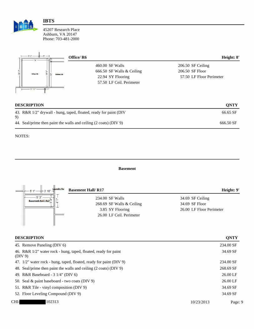
9
IBTS
45207 Research PlaceAshburn, VA 20147Phone: 703-481-2000
CHI- 102313 10/23/2013 Page: 9
Office/ R6 Height: 8'
460.00 SF Walls666.50 SF Walls & Ceiling22.94 SY Flooring57.50 LF Ceil. Perimeter
206.50 SF Ceiling206.50 SF Floor57.50 LF Floor Perimeter
DESCRIPTION QNTY
43. R&R 1/2" drywall - hung, taped, floated, ready for paint (DIV 66.65 SF9)
44. Seal/prime then paint the walls and ceiling (2 coats) (DIV 9) 666.50 SF
NOTES:
Basement
Basement Hall/ R17 Height: 9'
234.00 SF Walls268.69 SF Walls & Ceiling
3.85 SY Flooring26.00 LF Ceil. Perimeter
34.69 SF Ceiling34.69 SF Floor26.00 LF Floor Perimeter
DESCRIPTION QNTY
45. Remove Paneling (DIV 6) 234.00 SF
46. R&R 1/2" water rock - hung, taped, floated, ready for paint 34.69 SF(DIV 9)
47. 1/2" water rock - hung, taped, floated, ready for paint (DIV 9) 234.00 SF
48. Seal/prime then paint the walls and ceiling (2 coats) (DIV 9) 268.69 SF
49. R&R Baseboard - 3 1/4" (DIV 6) 26.00 LF
50. Seal & paint baseboard - two coats (DIV 9) 26.00 LF
51. R&R Tile - vinyl composition (DIV 9) 34.69 SF
52. Floor Leveling Compound (DIV 9) 34.69 SF

10
IBTS
45207 Research PlaceAshburn, VA 20147Phone: 703-481-2000
CHI- 102313 10/23/2013 Page: 10
CONTINUED - Basement Hall/ R17
DESCRIPTION QNTY
53. R&R Light fixture (DIV 16) 1.00 EA
54. Smoke detector (DIV 16) 1.00 EA
55. R&R Heat/AC register (DIV 15) 1.00 EA
56. Bifold door - Colonist - Single (DIV 8) 1.00 EA
57. Paint door slab only - 2 coats (per side) (DIV 9) 2.00 EA
58. Paint door/window trim & jamb - 2 coats (per side) (DIV 9) 2.00 EA
NOTES:
Laundry Room/ R19 Height: 7'
292.83 SF Walls373.32 SF Walls & Ceiling
8.94 SY Flooring41.83 LF Ceil. Perimeter
80.49 SF Ceiling80.49 SF Floor41.83 LF Floor Perimeter
DESCRIPTION QNTY
59. Batt insulation - 12" - R38 (DIV 7) 80.49 SF
60. Remove Paneling (DIV 6) 146.42 SF
61. 1/2" water rock - hung, taped, floated, ready for paint (DIV 9) 146.42 SF
62. 1/2" water rock - hung, taped, floated, ready for paint (DIV 9) 146.42 SF
63. Seal/prime then paint part of the walls (2 coats) (DIV 9) 146.42 SF

11
IBTS
45207 Research PlaceAshburn, VA 20147Phone: 703-481-2000
CHI- 102313 10/23/2013 Page: 11
CONTINUED - Laundry Room/ R19
DESCRIPTION QNTY
NOTES:
Basement Room/ R18 Height: 7'
311.50 SF Walls431.75 SF Walls & Ceiling13.36 SY Flooring44.50 LF Ceil. Perimeter
120.25 SF Ceiling120.25 SF Floor44.50 LF Floor Perimeter
DESCRIPTION QNTY
64. Remove Paneling (DIV 6) 311.50 SF
65. 1/2" water rock - hung, taped, floated, ready for paint (DIV 9) 311.50 SF
66. R&R 1/2" water rock - hung, taped, floated, ready for paint 120.25 SF(DIV 9)
67. Seal/prime then paint the walls and ceiling (2 coats) (DIV 9) 431.75 SF
68. Baseboard - 3 1/4" (DIV 6) 44.50 LF
69. Seal & paint baseboard - two coats (DIV 9) 44.50 LF
70. Tile - vinyl composition (DIV 9) 120.25 SF
71. Floor Leveling Compound (DIV 9) 120.25 SF
72. R&R Interior door unit - Pre-ung unit (08211) 1.00 EA
73. R&R Door knob - interiore (DIV 8) 1.00 EA
74. R&R Bypass (sliding) door set - Colonist (DIV 8) 1.00 EA
75. Paint door slab only - 2 coats (per side) (DIV 9) 4.00 EA
76. Paint door/window trim & jamb - 2 coats (per side) (DIV 9) 4.00 EA
77. Smoke detector (DIV 16) 1.00 EA
78. R&R Light fixture (DIV 16) 1.00 EA
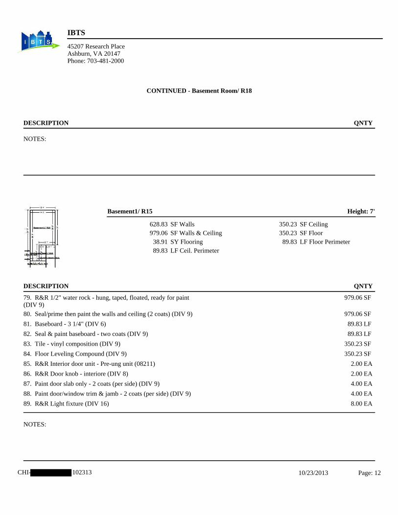
12
IBTS
45207 Research PlaceAshburn, VA 20147Phone: 703-481-2000
CHI- 102313 10/23/2013 Page: 12
CONTINUED - Basement Room/ R18
DESCRIPTION QNTY
NOTES:
Basement1/ R15 Height: 7'
628.83 SF Walls979.06 SF Walls & Ceiling38.91 SY Flooring89.83 LF Ceil. Perimeter
350.23 SF Ceiling350.23 SF Floor89.83 LF Floor Perimeter
DESCRIPTION QNTY
79. R&R 1/2" water rock - hung, taped, floated, ready for paint 979.06 SF(DIV 9)
80. Seal/prime then paint the walls and ceiling (2 coats) (DIV 9) 979.06 SF
81. Baseboard - 3 1/4" (DIV 6) 89.83 LF
82. Seal & paint baseboard - two coats (DIV 9) 89.83 LF
83. Tile - vinyl composition (DIV 9) 350.23 SF
84. Floor Leveling Compound (DIV 9) 350.23 SF
85. R&R Interior door unit - Pre-ung unit (08211) 2.00 EA
86. R&R Door knob - interiore (DIV 8) 2.00 EA
87. Paint door slab only - 2 coats (per side) (DIV 9) 4.00 EA
88. Paint door/window trim & jamb - 2 coats (per side) (DIV 9) 4.00 EA
89. R&R Light fixture (DIV 16) 8.00 EA
NOTES:

13
IBTS
45207 Research PlaceAshburn, VA 20147Phone: 703-481-2000
CHI- 102313 10/23/2013 Page: 13
Bathroom(Base)/ R16 Height: 6' 11"
183.29 SF Walls219.39 SF Walls & Ceiling
4.01 SY Flooring26.50 LF Ceil. Perimeter
36.10 SF Ceiling36.10 SF Floor26.50 LF Floor Perimeter
DESCRIPTION QNTY
90. R&R 1/2" water rock - hung, taped, floated, ready for paint 54.43 SF(DIV 9)
91. Seal/prime then paint the walls and ceiling (2 coats) (DIV 9) 219.39 SF
92. Remove Ceramic tile (DIV 9)(Flooring) 36.10 SF
93. Tile - vinyl composition (DIV 9) 36.10 SF
94. Floor Leveling Compound (DIV 9) 36.10 SF
95. Detach & Reset Pedestal sink (DIV 15) 1.00 EA
96. R&R Light fixture (DIV 16) 1.00 EA
97. Heat/AC register (DIV 15) 1.00 EA
98. R&R Toilet (DIV 15) 1.00 EA
99. R&R Fiberglass shower unit (DIV 15) 1.00 EA
NOTES:
Basement Stairs/ R14 Height: 8'
133.33 SF Walls150.52 SF Walls & Ceiling
1.91 SY Flooring16.67 LF Ceil. Perimeter
17.19 SF Ceiling17.19 SF Floor16.67 LF Floor Perimeter
DESCRIPTION QNTY
100. R&R 1/2" water rock - hung, taped, floated, ready for paint 15.05 SF(DIV 9)

14
IBTS
45207 Research PlaceAshburn, VA 20147Phone: 703-481-2000
CHI- 102313 10/23/2013 Page: 14
CONTINUED - Basement Stairs/ R14
DESCRIPTION QNTY
101. Seal/prime then paint the walls and ceiling (2 coats) (DIV 9) 150.52 SF
102. Stairway Repair (Basement Stairs) (DIV 6) 1.00 EA
NOTES:
Sencond Floor
Stairs/R7 Height: 15'
250.00 SF Walls267.02 SF Walls & Ceiling
1.89 SY Flooring16.67 LF Ceil. Perimeter
17.02 SF Ceiling17.02 SF Floor16.67 LF Floor Perimeter
DESCRIPTION QNTY
103. R&R 1/2" drywall - hung, taped, floated, ready for paint 26.70 SF(DIV 9)
104. Seal/prime then paint the walls and ceiling (2 coats) (DIV 9) 267.02 SF
NOTES:

15
IBTS
45207 Research PlaceAshburn, VA 20147Phone: 703-481-2000
CHI- 102313 10/23/2013 Page: 15
Hallway/ R8 Height: 8'
397.33 SF Walls464.40 SF Walls & Ceiling
7.45 SY Flooring49.67 LF Ceil. Perimeter
67.06 SF Ceiling67.06 SF Floor49.67 LF Floor Perimeter
DESCRIPTION QNTY
105. R&R 1/2" drywall - hung, taped, floated, ready for paint 46.44 SF(DIV 9)
106. Seal/prime then paint the walls and ceiling (2 coats) (DIV 9) 464.40 SF
107. Smoke detector (DIV 16) 1.00 EA
NOTES:
Bathroom(Up)/ R11 Height: 8'
274.67 SF Walls341.67 SF Walls & Ceiling
7.44 SY Flooring34.33 LF Ceil. Perimeter
67.00 SF Ceiling67.00 SF Floor34.33 LF Floor Perimeter
DESCRIPTION QNTY
108. R&R 1/2" water rock - hung, taped, floated, ready for paint 34.17 SF(DIV 9)
109. Seal/prime then paint the walls and ceiling (2 coats) (DIV 9) 341.67 SF
110. R&R Interior door unit - Pre-ung unit (08211) 1.00 EA
111. R&R Door knob - interiore (DIV 8) 1.00 EA
112. Paint door slab only - 2 coats (per side) (DIV 9) 2.00 EA
113. Paint door/window trim & jamb - 2 coats (per side) (DIV 9) 2.00 EA

16
IBTS
45207 Research PlaceAshburn, VA 20147Phone: 703-481-2000
CHI- 102313 10/23/2013 Page: 16
CONTINUED - Bathroom(Up)/ R11
DESCRIPTION QNTY
NOTES:
Bathroom(Master)/ R10 Height: 8'
224.00 SF Walls269.00 SF Walls & Ceiling
5.00 SY Flooring28.00 LF Ceil. Perimeter
45.00 SF Ceiling45.00 SF Floor28.00 LF Floor Perimeter
DESCRIPTION QNTY
114. R&R 1/2" water rock - hung, taped, floated, ready for paint 101.00 SF(DIV 9)
115. Seal/prime then paint the walls and ceiling (2 coats) (DIV 9) 269.00 SF
116. R&R Light fixture (DIV 16) 1.00 EA
117. Demolish/remove- General (Old/Existing Tub) (DIV 2) 45.00 SF
118. R & R fiberglass tub/shower combo-hardware & fixtures 1.00 EAincluded (DIV 15)
NOTES:

17
IBTS
45207 Research PlaceAshburn, VA 20147Phone: 703-481-2000
CHI- 102313 10/23/2013 Page: 17
Bedroom1(F)/ R9 Height: 8'
476.00 SF Walls697.18 SF Walls & Ceiling24.58 SY Flooring59.50 LF Ceil. Perimeter
221.18 SF Ceiling221.18 SF Floor59.50 LF Floor Perimeter
DESCRIPTION QNTY
119. R&R 1/2" drywall - hung, taped, floated, ready for paint 174.30 SF(DIV 9)
120. Seal/prime then paint the walls and ceiling (2 coats) (DIV 9) 697.18 SF
121. R&R Carpet (DIV 9) 221.18 SF
122. R&R Carpet pad (DIV 9) 221.18 SF
123. Smoke detector (DIV 16) 1.00 EA
NOTES:
Bedroom2(M)/ R12 Height: 8'
349.33 SF Walls468.06 SF Walls & Ceiling13.19 SY Flooring43.67 LF Ceil. Perimeter
118.73 SF Ceiling118.73 SF Floor43.67 LF Floor Perimeter
DESCRIPTION QNTY
124. R&R 1/2" drywall - hung, taped, floated, ready for paint 153.66 SF(DIV 9)
125. Seal/prime then paint the walls and ceiling (2 coats) (DIV 9) 468.06 SF
126. R&R Carpet (DIV 9) 118.73 SF
127. R&R Carpet pad (DIV 9) 118.73 SF
128. R&R Light fixture (DIV 16) 1.00 EA
129. Smoke detector (DIV 16) 1.00 EA

18
IBTS
45207 Research PlaceAshburn, VA 20147Phone: 703-481-2000
CHI- 102313 10/23/2013 Page: 18
CONTINUED - Bedroom2(M)/ R12
DESCRIPTION QNTY
130. R&R Heat/AC register (DIV 15) 1.00 EA
NOTES:
Bedroom3(Rear)/ R13 Height: 8'
378.67 SF Walls517.33 SF Walls & Ceiling15.41 SY Flooring47.33 LF Ceil. Perimeter
138.67 SF Ceiling138.67 SF Floor47.33 LF Floor Perimeter
DESCRIPTION QNTY
131. Remove Paneling (DIV 6) 378.67 SF
132. 1/2" drywall - hung, taped, floated, ready for paint (DIV 9) 378.67 SF
133. R&R 1/2" drywall - hung, taped, floated, ready for paint 13.87 SF(DIV 9)
134. Seal/prime then paint the walls and ceiling (2 coats) (DIV 9) 517.33 SF
135. R&R Baseboard - 3 1/4" (DIV 6) 47.33 LF
136. Seal & paint baseboard - two coats (DIV 9) 47.33 LF
137. Smoke detector (DIV 16) 1.00 EA
NOTES:

19
IBTS
45207 Research PlaceAshburn, VA 20147Phone: 703-481-2000
CHI- 102313 10/23/2013 Page: 19
Grand Total Areas:11,427.12 SF Walls 5,773.78 SF Ceiling SF Walls and Ceiling17,200.905,773.78 SF Floor 641.53 SY Flooring 1,128.17 LF Floor Perimeter1,292.00 SF Long Wall 836.00 SF Short Wall 1,128.17 LF Ceil. Perimeter
2,781.78 Floor Area 3,023.02 Total Area 7,171.13 Interior Wall Area4,772.53 Exterior Wall Area 532.63 Exterior Perimeter of
Walls
0.00 Surface Area 0.00 Number of Squares 0.00 Total Perimeter Length0.00 Total Ridge Length 0.00 Total Hip Length

20
CHI- 102313 10/23/2013 Page: 20
Sencond Floor

21
CHI- 102313 10/23/2013 Page: 21
Main Level

22
CHI- 102313 10/23/2013 Page: 22
Basement

23
Report Index
10/23/2013 i
Price List And Estimate Info 1 Line Item Detail 2
Grand Total Areas 19 Sketch 20

Limited Asbestos Survey Report Residence Page 1 of 11
Evanston, IL
Limited Asbestos Survey Report
Residence
Evanston, Illinois
Prepared for:
CDM Smith Inc. 125 South Wacker Drive Suite 600
Chicago, Illinois 60606
Prepared by:
Environmental Design International, inc. 33 West Monroe Street
Suite 1825 Chicago, Illinois 60603
(312) 345-1400
EDI Project Number: 1361.026
September 18, 2013
Gary Flentge Patricia Feeley Asbestos Inspector Technical Reviewer IL License 100-03472
#332

Limited Asbestos Survey Report Residence Page 2 of 11
Evanston, IL
TABLE OF CONTENTS
1.0 SUMMARY ......................................................................................................................................................... 3
2.0 GENERAL PROJECT INFORMATION ............................................................................................................ 4
2.1 GENERAL INFORMATION .......................................................................................................................... 4
2.2 AUTHORIZATION AND ACCESS ............................................................................................................... 4
2.3 PURPOSE AND REGULATIONS ................................................................................................................. 4
2.4 WARRANTY AND LIMITATIONS .............................................................................................................. 5
3.0 SCOPE OF SERVICES ........................................................................................................................................ 6
4.0 ASBESTOS SURVEY ......................................................................................................................................... 7
4.1 METHODOLOGY ........................................................................................................................................... 7
4.2 ASBESTOS RESULTS ................................................................................................................................... 7
5.0 FINDINGS AND RECOMMENDATIONS ........................................................................................................ 9
5.1 HAZARD ASSESSMENT ............................................................................................................................... 9
5.2 ASBESTOS HAZARD CATEGORIZATION ..................................................................................................... 10
5.3 PRESUMED ASBESTOS CONTAINING MATERIAL .................................................................................... 11
Appendices Appendix A Photographs and Sample Log Sheet Appendix B: ACM Drawing, Laboratory Report of Asbestos samples, & Laboratory Certification Appendix C: Inspector License and Certificates Appendix D: Glossary

Limited Asbestos Survey Report Residence Page 3 of 11
Evanston, IL
1.0 SUMMARY Environmental Design International inc. (EDI) was retained by CDM Smith Inc to conduct a Limited Asbestos Survey in accordance with the United States Environmental Protection Agency (USEPA) Asbestos in Buildings: Simplified Sampling Scheme for Friable Surfacing Materials (USEPA 560/5085-030a, October 1985). This project is part of the Illinois Ike Disaster Recovery Program and is one step in the applicant’s request for disaster relief assistance funding. This project is part of the Damage Assessment. CDM Smith is acting as the IDRP Program Manager on behalf of the State of Illinois. The following summarizes the General Project Information
Residence: Evanston, IL Date of Assessment: August 26 & 29, 2013 Survey performed by: Gary Flentge, Illinois Licensed Asbestos Inspector (IL License 100-
03472) Report prepared by: Caitlin Ford, EDI Task Manager
This report should be read in its entirety, including detailed information that is contained in other sections and appendices. The survey included a visual inspection of accessible areas of the house to identify suspect asbestos containing materials (ACM) and identify similar suspect materials into homogenous areas (HAs). The following suspect ACM was identified and sampled: floor tile and mastic, ceiling tile, and drywall. Asbestos was detected below the regulatory level of one percent in samples of the following materials:
White drywall composite had trace asbestos (Throughout basement)
The drywall composite sample had a trace detection of asbestos. EDI recommends the material be handled as ACM with regards to worker and occupant protection. Asbestos was detected above the regulatory level of one percent in samples of the following materials:
12”x12” floor tile and associated black mastic, multi-layered, Room 15-basement Black mastic associated with brown 12”x12” floor tile, multi-layered Room 18-basement Joint compound (throughout basement)
This report provides a summary of the results, findings and recommendations, and supporting documentation in the Appendices.

Limited Asbestos Survey Report Residence Page 4 of 11
Evanston, IL
2.0 GENERAL PROJECT INFORMATION
2.1 GENERAL INFORMATION Applicant: Resident Location: Evanston, IL Date of Assessment: August 26 & 29, 2013 Assessment Performed by: Gary Flentge Data Collected: 12 samples collected and tested by PLM Description/Area of Damage: Flooding damage in the basement. The property is a single family home, built circa 1960. This report was prepared by Caitlin Ford of Environmental Design International inc (EDI). The Limited Asbestos Survey was conducted following United States Environmental Protection Agency (USEPA) Asbestos in Buildings: Simplified Sampling Scheme for Friable Surfacing Materials (USEPA 560/5085-030a, October 1985); USEPA Asbestos Hazard Emergency Response Act (AHERA); the Illinois Administrative Code Title 77 Section 855 IDPH Notification and Procedures for Abatement of Asbestos in Commercial and Public Buildings; and following our subcontractor agreement with CDM Smith.
2.2 AUTHORIZATION AND ACCESS Authorization to perform this testing and risk assessment was given by CDM Smith Inc. in the form of an executed Subcontract Agreement. Access to the residence was arranged by IBTS as part of the Damage Assessment.
2.3 PURPOSE AND REGULATIONS The purpose of the limited asbestos survey is to identify ACM that will need to be abatement prior to renovation. Building materials that contain more than 1% asbestos are considered to be ACM by Federal and State Regulations. Regulated asbestos to be abated prior to demolition is in the form of friable asbestos. Asbestos removal is regulated in Illinois Administrative Code Title 77 Section 855 IDPH Notification and Procedures for Abatement of Asbestos in Commercial and Public Buildings. Codes of Federal Regulations (CRF) governing asbestos include 29 CFR 1910.1001 OSHA, 29 CFR 1910.20 OSHA General Safety and Health Provisions, and 40 CFR 61 Subpart M National Emissions Standards for Hazardous Air Pollutants (NESHAP) and 40 CFR Part 763 Asbestos. The NESHAP regulations define asbestos into Category I and II materials and into friable and non-friable categories. Category I material is defined as asbestos-containing resilient floor covering, asphalt roofing products, packings and gaskets. Asbestos-containing mastic is also considered a Category I material (EPA determination - April 9, 1991). Category II material is defined as all remaining types of non-friable ACM not included in Category I that, when dry, cannot be

Limited Asbestos Survey Report Residence Page 5 of 11
Evanston, IL
crumbled, pulverized, or reduced to powder by hand pressure. Nonfriable asbestos-cement products such as transite are an example of Category II material. This information can be found on the EPA website for Region 5 under Air and Asbestos. Examples of Category II or Friable ACM that must be removed prior to building demolition include TSI on piping, drywall and joint compound, transite walls and ceilings, broken floor tile and associated mastic.
2.4 WARRANTY AND LIMITATIONS The information contained in this report is based upon the data available as of the date of the survey and collected at the residence during the survey by EDI. These observations and results are time dependent, are subject to changing site conditions, and revisions to Federal, state, and local regulations. All materials tested are assumed homogeneous throughout the proposed work areas. Every attempt was made to thoroughly evaluate and assess the presence and condition of suspect ACM. EDI did not perform destructive sampling practices and suspect materials may exist within occupied or inaccessible areas. Any suspect material identified during renovation that is not specifically listed herein should be thoroughly assessed, sampled and analyzed prior to disturbance, in accordance with applicable regulatory standards.
The findings and conclusions in this report are not specific certainties; rather they are probabilities based on professional judgment concerning the significance of the data collected. EDI claims to represent only the specific findings documented herein and does not claim knowledge of conditions beyond the scope of the limited survey. The limited asbestos survey was conducted in a manner consistent with that level of care and skill ordinarily exercised by members of the environmental profession under similar conditions. No other warranty or guarantee, express or implied, is included or intended in this Report or otherwise.
The survey and analytical methods have been used to provide the client with information regarding the presence of accessible and/or exposed ACM existing in the facility at the time of survey. Test results are valid only for the material tested. There is a distinct possibility that conditions may exist which could not be identified within the scope of the study or which were not apparent during the site visit. This survey covered only those areas which were exposed and/or physically accessible to the inspector. EDI also recognizes that laboratory test data are usually not sufficient to make all abatement and management decisions and recommends that EDI be afforded an opportunity to review abatement specification so test results may be properly interpreted and implemented. This report has been prepared for the exclusive use of the Client for the building at the subject site. It is not intended for the use or benefit of any other party.

Limited Asbestos Survey Report Residence Page 6 of 11
Evanston, IL
3.0 SCOPE OF SERVICES The scope of services requested by CDM Smith Inc. included the on-site inspection for observed suspect ACM materials and sample collection; sample analysis by PLM at a certified laboratory; and preparation of this report. The report includes project information, inspection photographs of suspect materials sampled, sample analysis and data, findings and recommendations, and signature and qualifications of the inspector. A list of results by homogenous area is included in the report and the laboratory results are provided in Appendix B of this report. Estimated quantities are provided, however, all materials may not be accessible at the time of the inspection. The scope of construction projects can change. The asbestos inspection report must be reviewed, and untested suspect ACM in the path of construction should be tested, before any work begins. Asbestos hazards are discussed in this report; however, the asbestos survey is not an asbestos abatement design. Based upon conversations with the applicant/resident and CDM Smith Inc. (Client), to the knowledge of this Inspector, there has not been any previous ACM testing at this home. Roofing materials are typically not sampled due to concerns about maintaining the integrity of the building envelope, and existing warranties. Samples were collected to be minimally invasive or damaging and to be representative.

Limited Asbestos Survey Report Residence Page 7 of 11
Evanston, IL
4.0 ASBESTOS SURVEY
4.1 METHODOLOGY The ACM survey was performed in accordance with the United States Environmental Protection Agency (USEPA) Asbestos in Buildings: Simplified Sampling Scheme for Friable Surfacing Materials (USEPA 560/5085-030a, October 1985). Similar building components were grouped into homogenous sampling areas (HAs). HAs are areas containing materials that are similar in color, texture, and general appearance, and which appear to have been uniformly installed during the same time period. The asbestos sampling included interior and exterior building materials, such as floor tiles, pipe insulation, window caulks, and transite. The materials were collected to sample all layers on a building component. The laboratory analyzed multi-layer samples separately. Roofs were generally not sampled. Bulk samples of suspect ACM were collected using wet sampling methods with a sample cutter, as appropriate, to collect a cross-section of the suspect ACM. Sample collection tools were decontaminated after each sample by washing with soap and water and dried by disposable towels to avoid cross contamination. Bulk ACM samples were placed into clean unused bags marked with a unique sample identification number. For each sample, the identification number, brief material description, location, and estimated quantity of suspect ACM were recorded on a bulk sample log sheet (provided in Appendix A). Chain-of-Custody (COC) procedures were followed for the ACM survey. These procedures provide a written tracking mechanism that lists the person responsible for the sample from collection to delivery to the laboratory. Sample identification numbers, sample locations, and material descriptions were recorded on the chain-of-custody forms. The COC forms are provided with the laboratory bulk sample log sheet. Sample locations are shown in the drawings in Appendix B. All samples were analyzed by International Asbestos Testing Laboratories (IATL) in Laurel, New Jersey, a National Voluntary Laboratory Accreditation Program (NVLAP) accredited asbestos laboratory. Bulk samples were analyzed by polarized light microscopy (PLM), utilizing a light microscope equipped with polarized filters (USEPA Method 600/R-93/116). The laboratory report is provided in Appendix B. Current laboratory accreditation is provided in Appendix B. 4.2 ASBESTOS RESULTS A material is considered by the EPA to be asbestos containing if at least one sample collected from the area shows asbestos present in an amount greater than one percent (>1%). The visual survey identified HAs and below is a list of the suspect materials sampled. Non-suspect materials, such as fiberglass piping wrap, foam rubber, and wood products are identified in the field during the visual survey and not sampled. Photographs of the visual survey and suspect materials are included with Appendix A for review. The asbestos sample log is included in Appendix A. Samples were collected from the following suspect materials:

Limited Asbestos Survey Report Residence Page 8 of 11
Evanston, IL
o 12”x12” floor tile and mastic, multi-layered, basement (Room 15) o 12”x12” floor tile and mastic, multi-layered, basement (Room 18) o Ceiling tile, basement (Room 15) o Drywall, tape, and joint compound, basement (throughout basement)
The samples were submitted under chain of custody to IATL for laboratory analysis of asbestos by PLM. The laboratory report of the analysis results is included in Appendix B with the laboratory certification. A drawing showing the samples collected and the laboratory reported ACM is included in Appendix B. Asbestos was detected above the regulatory level of one percent in samples of the following materials: 12”x12” floor tile and associated black mastic, multi-layered (Room 15-basement) Black mastic associated with brown 12”x12” floor tile, multi-layered (Room 18-basement) Joint compound (throughout basement)
Asbestos was detected below the regulatory level of one percent in samples of the following materials: White drywall composite had trace asbestos (Throughout basement, tested DWTC1-010,
room 15)
**Special Note on Composite Drywall, Tape and Joint Compound Sampling & Analysis** Based on composite sampling protocol recognized by EPA for drywall, tape and joint compound, together with an analysis protocol recognized by EPA for composite analysis of a composite sample of drywall, tape and joint compound; it is possible for one of the layered materials that comprise the composite drywall, tape and joint compound sample to be reported as >1% asbestos. When the composite sample is analyzed as a composite material in accordance with the EPA recognized laboratory method, the result may be less that 1%. Asbestos was detected in one of the layers of the composite drywall, tape and joint compound at >1%, specifically the joint compound at this property. Analysis by EPA-recognized composite analytical method subsequently indicate that the composite drywall, tape and joint compound systems as <1% and/or trace results for asbestos. EDI recommends the material be handled as ACM with regards to worker and occupant protection. Any materials identified in any other part of the unit that are similar and homogeneous to those identified as ACM herein, must be handled as ACM.

Limited Asbestos Survey Report Residence Page 9 of 11
Evanston, IL
5.0 FINDINGS AND RECOMMENDATIONS
5.1 HAZARD ASSESSMENT Suspect materials from which samples were collected were assessed and categorized by hazard level. The location and estimated quantity of the material, the condition of the material, accessibility of the material, potential for disturbance, and exposure to air movement, vibration, and water were considered in the assessment.
Based on the described conditions and laboratory analysis results, materials which were sampled were classified into one of the following categories:
Asbestos Hazard Categorization List:
C-1 Asbestos Present - Serious Health Hazard; Abatement should be top
priority C-2 Asbestos Present - Health Hazard; Abatement should be
planned C-3 Asbestos Present - No Action Necessary Unless Renovation,
Remodeling, or Demolition is Planned B-1 Asbestos Present - Contains 1% asbestos, or less
B-2 Asbestos Present - Adequately Enclosed
B-3 Asbestos Present - Adequately Encapsulated
A No Asbestos Found
A-1 Asbestos Abated - Once Identified Asbestos Containing Materials have been
abated.

Limited Asbestos Survey Report Residence Page 10 of 11
Evanston, IL
The Response Action Options for asbestos-containing materials are listed as follows:
Operations and Maintenance
The materials are maintained in an undamaged condition and monitored so that the potential for disturbance is minimized. Implementation of an Operations and Maintenance (O & M) Plan involves repair or removal of damaged materials, record keeping, worker training, inspections and air monitoring.
Encapsulation Surfaces of the ACM are sealed with a bridging-type encapsulant or the ACM is rendered non-friable with a penetrating type encapsulant. The material is disturbed during application of this method therefore a controlled work area is required.
Enclosure The materials are isolated behind air-tight barriers such as gyp-board or plywood walls so that they are inaccessible to building occupants. A controlled work area is required for this method so that asbestos does not contaminate the building.
Removal ACM is removed and properly disposed of by a licensed abatement contractor under asbestos control conditions.
5.2 ASBESTOS HAZARD CATEGORIZATION The following table lists the Asbestos Hazard Categorization, recommended response action, and estimated quantity for the materials identified in the inspection.
Material Location Hazard Category
Recommended Response
Action
Estimated Quantity
AHERA
12”x12” Floor tile and
associated black mastic
(multi-layered)
Room 15 C-3 O&M 300-350 S.F. 5
Black mastic associated with brown
12”x12” floor tile (multi-layered)
Room 18 C-3 O&M 120 S.F. 5
Drywall Joint compound
Throughout basement
C-3 O&M * 5
*Estimated quantity to be determined by IBTS based on damage assessment.

Limited Asbestos Survey Report Residence Page 11 of 11
Evanston, IL
Note: Certain materials such as piping, and multiple layered ceiling applications and floor coverings may not be totally visible due to their location behind other materials. Quantities of such materials are estimated. Once affected areas become vacant and appropriate authorization is obtained, more destructive investigation and quantification may be feasible.
Drawings showing the asbestos by homogenous areas are found in Appendix B.
AHERA CLASSIFICATION
The assessment of asbestos-containing materials by an accredited inspector is required by EPA AHERA regulations (40 CFR 763 Subpart E). The ACM is classified into one of the following categories:
(1) Damaged or significantly damaged thermal system insulation ACM. (2) Damaged friable surfacing ACM. (3) Significantly damaged friable surfacing ACM. (4) Damaged or significantly damaged friable miscellaneous ACM. (5) ACBM with potential for damage. (6) ACBM with potential for significant damage. (7) Any remaining friable ACBM or friable suspected ACBM.
The AHERA classification for the ACM identified in the inspection is presented in the sample summary table in the Appendix.
This Inspection Report is not an Abatement Specification, and should not be used for bidding purposes. Quantities stated herein are approximate, and must be field verified before commencing any abatement activities. An Abatement Specification must be prepared by a Licensed Asbestos Consultant prior to abatement, and all removal must be performed by a licensed Asbestos Contractor.
5.3 PRESUMED ASBESTOS CONTAINING MATERIAL
Building materials such as thermal insulation in pipe chases, multiple layered ceiling applications and floor coverings, and vapor barriers behind exterior facades are typically inaccessible to the inspector, and are therefore assumed to be asbestos-containing. Before commencing renovation or demolition activities the presence of such materials can be investigated, and if found, the asbestos content can be verified by laboratory analysis.

Appendices

9000 Commerce Parkway, Suite B •Mount Laurel, NJ 08054
Phone: 877-428-4285/856-231-9449 •Fax: 856-231-9818
Sample Log -Bulk Asbestos -
Client:_E_D_l _____________ Project:
Sampling Date/Time: ~ /_,,z'-. c._1_.f-"l=3c....., _________ _
Client Sample #
til -ooi -003
FT2 ·-CCJli -cd.J.
c~11 ·-a1t-oel) b.\.stp.- ul O~p
c)f2.
Fn -001 oo 'J 60)
r-T;).- CO'-{
aos-{\(\ {
(T\ - cxn 008
DWi'"Ll- (j\ c 0\\
(i) •)-
Bulk Asbestos Sample Log
iATL# Location/Descriotion i .2 "' 11'12:'1 A..:t."h' le ( ~~t1£'.,.,,. 00tLn \.JV>(~) j ~1'6&\11-~I" i2!1 )(12• Aotritle ti W\.El.S:tte. \'11\M~n • l.Nii::4'/b() f. ·i~>E:'IM-~I c~,\ r~j ·r1'u; J ,~~{M/\~r
£)i"'if\ASt'tl \ 1Th\)~~ ·:J> 1 l'-fr <l">'Mft1,V£ 'l> M:,.. •• ~· -
•"••af'l.1' ., .. , •..f.lV•J,.,J. l
51091.18 ~18~1-A''' ~ '"'"t ~ . 5 U'jl&:. ~
,. c'i"' c:; l~J- 4
~ l • 2 ul }tt i~i ~ ...
_,...-i;<)i:,
5iti§tZG - ~ ~,... .. I')..., ;) !U-V _._ -w -r·
~1091.28 I ~ q I< ) 1.1 .
Cclcbrnting years ... one sample at <i
www.iatl.com
Notes {LJ::t'J1<'V\. 15 iv ~'JO -31)(,f;F
112.co<"tl\ \t> ,..._ \WSF
(tc-0~1\'\. \ 6 ,.,_, lj!)5~
'\fa
- 2-

Appendix B

2
CHI- 9/9/2013 Page: 2
Sencond Floor

3
CHI- 9/9/2013 Page: 3
Main Level

4
CHI- 9/9/2013 Page: 4
Basement

Asbestos Samples Results

9000 Commerce Parkway Suite B Mt. Laurel, NJ 08054
Telephone: 856-231-9449 Fax: 856-231-9818
International Asbestos
Testing Laboratories
IATL
CERTIFICATE OF ANALYSIS
(Revised)
Client:
Report Date:
Project No.:
Project:
BULK SAMPLE ANALYSIS SUMMARY
Environ. Design International
33 W Monroe, Suite 1825
Chicago IL 60603
1361.026
9/5/2013
Report No.: 313768
% Asbestos Type % Non-Asbestos Fibrous Material Type % Non-Fibrous Material
Client No.:
Lab No.:
FT1-001
5109117 Description / Location:
Rm 15; Basement
None Detected None Detected None Detected None Detected 100
Grey/Pink Floor Tile; 12x12
% Asbestos Type % Non-Asbestos Fibrous Material Type % Non-Fibrous Material
Client No.:
Lab No.:
FT1-001
5109117 Description / Location:
Rm 15; Basement
None Detected None Detected None Detected None Detected 100
Yellow Mastic Layer No.: 2
% Asbestos Type % Non-Asbestos Fibrous Material Type % Non-Fibrous Material
Client No.:
Lab No.:
FT1-001
5109117 Description / Location:
Rm 15; Basement
PC 6.5 Chrysotile None Detected None Detected PC 93.5
Orange/Tan Floor Tile Layer No.: 3
% Asbestos Type % Non-Asbestos Fibrous Material Type % Non-Fibrous Material
Client No.:
Lab No.:
FT1-001
5109117 Description / Location:
Rm 15; Basement
PC 2.5 Chrysotile None Detected None Detected PC 97.5
Black Mastic Layer No.: 4
NIST-NVLAP No. 101165-0 NY-DOH No. 11021 AIHA-LAP, LLC No. 100188
This confidential report relates only to those item(s) tested and does not represent an endorsement by NIST-NVLAP, AIHA or any agency of the U.S. government
This report shall not be reproduced except in full, without written approval of the laboratory.
EPA 600/R-93/116 By Polarized Light MicroscopyAnalytical Method:
Comments: (PC) Indicates Stratified Point Count Method performed. Method not performed unless stated. Quantification at <0.25% by volume is possible with this method. (PC–Trace) represents
this limit of quantitation. (PC-Trace) means that asbestos was detected but is not quantifiable under the Point Counting regimen. Analysis includes all distinct separable layers in
accordance with EPA 600 Method. If not reported or otherwise noted, layer is either not present or the client has specifically requested that it not be analyzed. Small asbestos fibers may
be missed by PLM due to resolution limitations of the optical microscope. Therefore, negative PLM results cannot be guaranteed. Electron Microscopy can be used as a confirming
technique. Regulatory Limit is based upon the sample matrix.
Analysis Performed By:
Date:
Approved By:
Frank E. Ehrenfeld, III
Laboratory Director
9/5/2013
Page 1 of 8
L. Solebello
_____________________________

9000 Commerce Parkway Suite B Mt. Laurel, NJ 08054
Telephone: 856-231-9449 Fax: 856-231-9818
International Asbestos
Testing Laboratories
IATL
CERTIFICATE OF ANALYSIS
(Revised)
Client:
Report Date:
Project No.:
Project:
BULK SAMPLE ANALYSIS SUMMARY
Environ. Design International
33 W Monroe, Suite 1825
Chicago IL 60603
1361.026
9/5/2013
Report No.: 313768
% Asbestos Type % Non-Asbestos Fibrous Material Type % Non-Fibrous Material
Client No.:
Lab No.:
FT1-002
5109118 Description / Location:
Rm 15; Basement
None Detected None Detected None Detected None Detected 100
Grey/Pink Floor Tile; 12x12
% Asbestos Type % Non-Asbestos Fibrous Material Type % Non-Fibrous Material
Client No.:
Lab No.:
FT1-002
5109118 Description / Location:
Rm 15; Basement
None Detected None Detected None Detected None Detected 100
Yellow Mastic Layer No.: 2
% Asbestos Type % Non-Asbestos Fibrous Material Type % Non-Fibrous Material
Client No.:
Lab No.:
FT1-002
5109118 Description / Location:
Rm 15; Basement
None Detected None Detected None Detected None Detected 100
Grey/Blue Floor Tile Layer No.: 3
% Asbestos Type % Non-Asbestos Fibrous Material Type % Non-Fibrous Material
Client No.:
Lab No.:
FT1-002
5109118 Description / Location:
Rm 15; Basement
None Detected None Detected None Detected None Detected 100
Yellow Mastic Layer No.: 4
NIST-NVLAP No. 101165-0 NY-DOH No. 11021 AIHA-LAP, LLC No. 100188
This confidential report relates only to those item(s) tested and does not represent an endorsement by NIST-NVLAP, AIHA or any agency of the U.S. government
This report shall not be reproduced except in full, without written approval of the laboratory.
EPA 600/R-93/116 By Polarized Light MicroscopyAnalytical Method:
Comments: (PC) Indicates Stratified Point Count Method performed. Method not performed unless stated. Quantification at <0.25% by volume is possible with this method. (PC–Trace) represents
this limit of quantitation. (PC-Trace) means that asbestos was detected but is not quantifiable under the Point Counting regimen. Analysis includes all distinct separable layers in
accordance with EPA 600 Method. If not reported or otherwise noted, layer is either not present or the client has specifically requested that it not be analyzed. Small asbestos fibers may
be missed by PLM due to resolution limitations of the optical microscope. Therefore, negative PLM results cannot be guaranteed. Electron Microscopy can be used as a confirming
technique. Regulatory Limit is based upon the sample matrix.
Analysis Performed By:
Date: 9/5/2013
Page 2 of 8
L. Solebello

9000 Commerce Parkway Suite B Mt. Laurel, NJ 08054
Telephone: 856-231-9449 Fax: 856-231-9818
International Asbestos
Testing Laboratories
IATL
CERTIFICATE OF ANALYSIS
(Revised)
Client:
Report Date:
Project No.:
Project:
BULK SAMPLE ANALYSIS SUMMARY
Environ. Design International
33 W Monroe, Suite 1825
Chicago IL 60603
1361.026
9/5/2013
Report No.: 313768
% Asbestos Type % Non-Asbestos Fibrous Material Type % Non-Fibrous Material
Client No.:
Lab No.:
FT1-003
5109119 Description / Location:
Rm 15; Basement
None Detected None Detected None Detected None Detected 100
Grey/Blue Floor Tile; 12x12
% Asbestos Type % Non-Asbestos Fibrous Material Type % Non-Fibrous Material
Client No.:
Lab No.:
FT1-003
5109119 Description / Location:
Rm 15; Basement
None Detected None Detected None Detected None Detected 100
Yellow Mastic Layer No.: 2
% Asbestos Type % Non-Asbestos Fibrous Material Type % Non-Fibrous Material
Client No.:
Lab No.:
FT1-003
5109119 Description / Location:
Rm 15; Basement
PC 1.7 Chrysotile None Detected None Detected PC 98.3
Black Mastic Layer No.: 3
NIST-NVLAP No. 101165-0 NY-DOH No. 11021 AIHA-LAP, LLC No. 100188
This confidential report relates only to those item(s) tested and does not represent an endorsement by NIST-NVLAP, AIHA or any agency of the U.S. government
This report shall not be reproduced except in full, without written approval of the laboratory.
EPA 600/R-93/116 By Polarized Light MicroscopyAnalytical Method:
Comments: (PC) Indicates Stratified Point Count Method performed. Method not performed unless stated. Quantification at <0.25% by volume is possible with this method. (PC–Trace) represents
this limit of quantitation. (PC-Trace) means that asbestos was detected but is not quantifiable under the Point Counting regimen. Analysis includes all distinct separable layers in
accordance with EPA 600 Method. If not reported or otherwise noted, layer is either not present or the client has specifically requested that it not be analyzed. Small asbestos fibers may
be missed by PLM due to resolution limitations of the optical microscope. Therefore, negative PLM results cannot be guaranteed. Electron Microscopy can be used as a confirming
technique. Regulatory Limit is based upon the sample matrix.
Analysis Performed By:
Date: 9/5/2013
Page 3 of 8
L. Solebello

9000 Commerce Parkway Suite B Mt. Laurel, NJ 08054
Telephone: 856-231-9449 Fax: 856-231-9818
International Asbestos
Testing Laboratories
IATL
CERTIFICATE OF ANALYSIS
(Revised)
Client:
Report Date:
Project No.:
Project:
BULK SAMPLE ANALYSIS SUMMARY
Environ. Design International
33 W Monroe, Suite 1825
Chicago IL 60603
1361.026
9/5/2013
Report No.: 313768
% Asbestos Type % Non-Asbestos Fibrous Material Type % Non-Fibrous Material
Client No.:
Lab No.:
FT2-004
5109120 Description / Location:
Rm 18; Basement
None Detected None Detected None Detected None Detected 100
Brown Floor Tile; 12x12
% Asbestos Type % Non-Asbestos Fibrous Material Type % Non-Fibrous Material
Client No.:
Lab No.:
FT2-004
5109120 Description / Location:
Rm 18; Basement
None Detected None Detected None Detected None Detected 100
Yellow Mastic Layer No.: 2
% Asbestos Type % Non-Asbestos Fibrous Material Type % Non-Fibrous Material
Client No.:
Lab No.:
FT2-004
5109120 Description / Location:
Rm 18; Basement
None Detected None Detected None Detected None Detected 100
Off-White Cementitious Layer No.: 3
NIST-NVLAP No. 101165-0 NY-DOH No. 11021 AIHA-LAP, LLC No. 100188
This confidential report relates only to those item(s) tested and does not represent an endorsement by NIST-NVLAP, AIHA or any agency of the U.S. government
This report shall not be reproduced except in full, without written approval of the laboratory.
EPA 600/R-93/116 By Polarized Light MicroscopyAnalytical Method:
Comments: (PC) Indicates Stratified Point Count Method performed. Method not performed unless stated. Quantification at <0.25% by volume is possible with this method. (PC–Trace) represents
this limit of quantitation. (PC-Trace) means that asbestos was detected but is not quantifiable under the Point Counting regimen. Analysis includes all distinct separable layers in
accordance with EPA 600 Method. If not reported or otherwise noted, layer is either not present or the client has specifically requested that it not be analyzed. Small asbestos fibers may
be missed by PLM due to resolution limitations of the optical microscope. Therefore, negative PLM results cannot be guaranteed. Electron Microscopy can be used as a confirming
technique. Regulatory Limit is based upon the sample matrix.
Analysis Performed By:
Date: 9/5/2013
Page 4 of 8
L. Solebello

9000 Commerce Parkway Suite B Mt. Laurel, NJ 08054
Telephone: 856-231-9449 Fax: 856-231-9818
International Asbestos
Testing Laboratories
IATL
CERTIFICATE OF ANALYSIS
(Revised)
Client:
Report Date:
Project No.:
Project:
BULK SAMPLE ANALYSIS SUMMARY
Environ. Design International
33 W Monroe, Suite 1825
Chicago IL 60603
1361.026
9/5/2013
Report No.: 313768
% Asbestos Type % Non-Asbestos Fibrous Material Type % Non-Fibrous Material
Client No.:
Lab No.:
FT2-005
5109121 Description / Location:
Rm 18; Basement
None Detected None Detected None Detected None Detected 100
Brown Floor Tile; 12x12
% Asbestos Type % Non-Asbestos Fibrous Material Type % Non-Fibrous Material
Client No.:
Lab No.:
FT2-005
5109121 Description / Location:
Rm 18; Basement
None Detected None Detected None Detected None Detected 100
Yellow Mastic Layer No.: 2
% Asbestos Type % Non-Asbestos Fibrous Material Type % Non-Fibrous Material
Client No.:
Lab No.:
FT2-006
5109122 Description / Location:
Rm 18; Basement
None Detected None Detected None Detected None Detected 100
Brown Floor Tile; 12x12
% Asbestos Type % Non-Asbestos Fibrous Material Type % Non-Fibrous Material
Client No.:
Lab No.:
FT2-006
5109122 Description / Location:
Rm 18; Basement
PC 3.3 Chrysotile None Detected None Detected PC 96.7
Black Mastic Layer No.: 2
NIST-NVLAP No. 101165-0 NY-DOH No. 11021 AIHA-LAP, LLC No. 100188
This confidential report relates only to those item(s) tested and does not represent an endorsement by NIST-NVLAP, AIHA or any agency of the U.S. government
This report shall not be reproduced except in full, without written approval of the laboratory.
EPA 600/R-93/116 By Polarized Light MicroscopyAnalytical Method:
Comments: (PC) Indicates Stratified Point Count Method performed. Method not performed unless stated. Quantification at <0.25% by volume is possible with this method. (PC–Trace) represents
this limit of quantitation. (PC-Trace) means that asbestos was detected but is not quantifiable under the Point Counting regimen. Analysis includes all distinct separable layers in
accordance with EPA 600 Method. If not reported or otherwise noted, layer is either not present or the client has specifically requested that it not be analyzed. Small asbestos fibers may
be missed by PLM due to resolution limitations of the optical microscope. Therefore, negative PLM results cannot be guaranteed. Electron Microscopy can be used as a confirming
technique. Regulatory Limit is based upon the sample matrix.
Analysis Performed By:
Date: 9/5/2013
Page 5 of 8
L. Solebello

9000 Commerce Parkway Suite B Mt. Laurel, NJ 08054
Telephone: 856-231-9449 Fax: 856-231-9818
International Asbestos
Testing Laboratories
IATL
CERTIFICATE OF ANALYSIS
(Revised)
Client:
Report Date:
Project No.:
Project:
BULK SAMPLE ANALYSIS SUMMARY
Environ. Design International
33 W Monroe, Suite 1825
Chicago IL 60603
1361.026
9/5/2013
Report No.: 313768
% Asbestos Type % Non-Asbestos Fibrous Material Type % Non-Fibrous Material
Client No.:
Lab No.:
CT1-007
5109123 Description / Location:
Rm 15; Basement
None Detected None Detected 80 Cellulose 20
White/Brown Ceiling Tile
% Asbestos Type % Non-Asbestos Fibrous Material Type % Non-Fibrous Material
Client No.:
Lab No.:
CT1-008
5109124 Description / Location:
Rm 15; Basement
None Detected None Detected 80 Cellulose 20
White/Brown Ceiling Tile
% Asbestos Type % Non-Asbestos Fibrous Material Type % Non-Fibrous Material
Client No.:
Lab No.:
CT1-009
5109125 Description / Location:
Rm 15; Basement
None Detected None Detected 80 Cellulose 20
White/Brown Ceiling Tile
NIST-NVLAP No. 101165-0 NY-DOH No. 11021 AIHA-LAP, LLC No. 100188
This confidential report relates only to those item(s) tested and does not represent an endorsement by NIST-NVLAP, AIHA or any agency of the U.S. government
This report shall not be reproduced except in full, without written approval of the laboratory.
EPA 600/R-93/116 By Polarized Light MicroscopyAnalytical Method:
Comments: (PC) Indicates Stratified Point Count Method performed. Method not performed unless stated. Quantification at <0.25% by volume is possible with this method. (PC–Trace) represents
this limit of quantitation. (PC-Trace) means that asbestos was detected but is not quantifiable under the Point Counting regimen. Analysis includes all distinct separable layers in
accordance with EPA 600 Method. If not reported or otherwise noted, layer is either not present or the client has specifically requested that it not be analyzed. Small asbestos fibers may
be missed by PLM due to resolution limitations of the optical microscope. Therefore, negative PLM results cannot be guaranteed. Electron Microscopy can be used as a confirming
technique. Regulatory Limit is based upon the sample matrix.
Analysis Performed By:
Date: 9/5/2013
Page 6 of 8
L. Solebello

9000 Commerce Parkway Suite B Mt. Laurel, NJ 08054
Telephone: 856-231-9449 Fax: 856-231-9818
International Asbestos
Testing Laboratories
IATL
CERTIFICATE OF ANALYSIS
(Revised)
Client:
Report Date:
Project No.:
Project:
BULK SAMPLE ANALYSIS SUMMARY
Environ. Design International
33 W Monroe, Suite 1825
Chicago IL 60603
1361.026
9/5/2013
Report No.: 313768
% Asbestos Type % Non-Asbestos Fibrous Material Type % Non-Fibrous Material
Client No.:
Lab No.:
DWTC1-010
5109126 Description / Location:
Basement; Throughout
None Detected None Detected 20 Cellulose 80
White/Tan Sheetrock
% Asbestos Type % Non-Asbestos Fibrous Material Type % Non-Fibrous Material
Client No.:
Lab No.:
DWTC1-010
5109126 Description / Location:
Basement; Throughout
PC 1.8 Chrysotile None Detected None Detected PC 98.2
Off-White Joint Compound Layer No.: 2
% Asbestos Type % Non-Asbestos Fibrous Material Type % Non-Fibrous Material
Client No.:
Lab No.:
DWTC1-010
5109126 Description / Location:
Basement; Throughout
Trace Chrysotile 20 Cellulose 80
Composite Layer No.: 3
NIST-NVLAP No. 101165-0 NY-DOH No. 11021 AIHA-LAP, LLC No. 100188
This confidential report relates only to those item(s) tested and does not represent an endorsement by NIST-NVLAP, AIHA or any agency of the U.S. government
This report shall not be reproduced except in full, without written approval of the laboratory.
EPA 600/R-93/116 By Polarized Light MicroscopyAnalytical Method:
Comments: (PC) Indicates Stratified Point Count Method performed. Method not performed unless stated. Quantification at <0.25% by volume is possible with this method. (PC–Trace) represents
this limit of quantitation. (PC-Trace) means that asbestos was detected but is not quantifiable under the Point Counting regimen. Analysis includes all distinct separable layers in
accordance with EPA 600 Method. If not reported or otherwise noted, layer is either not present or the client has specifically requested that it not be analyzed. Small asbestos fibers may
be missed by PLM due to resolution limitations of the optical microscope. Therefore, negative PLM results cannot be guaranteed. Electron Microscopy can be used as a confirming
technique. Regulatory Limit is based upon the sample matrix.
Analysis Performed By:
Date: 9/5/2013
Page 7 of 8
L. Solebello

9000 Commerce Parkway Suite B Mt. Laurel, NJ 08054
Telephone: 856-231-9449 Fax: 856-231-9818
International Asbestos
Testing Laboratories
IATL
CERTIFICATE OF ANALYSIS
(Revised)
Client:
Report Date:
Project No.:
Project:
BULK SAMPLE ANALYSIS SUMMARY
Environ. Design International
33 W Monroe, Suite 1825
Chicago IL 60603
1361.026
9/5/2013
Report No.: 313768
% Asbestos Type % Non-Asbestos Fibrous Material Type % Non-Fibrous Material
Client No.:
Lab No.:
DWTC1-011
5109127 Description / Location:
Basement; Throughout
None Detected None Detected 15
5
Cellulose
Fibrous Glass
80
White/Tan Sheetrock
% Asbestos Type % Non-Asbestos Fibrous Material Type % Non-Fibrous Material
Client No.:
Lab No.:
DWTC1-011
5109127 Description / Location:
Basement; Throughout
None Detected None Detected None Detected None Detected 100
White Joint Compound Layer No.: 2
% Asbestos Type % Non-Asbestos Fibrous Material Type % Non-Fibrous Material
Client No.:
Lab No.:
DWTC1-011
5109127 Description / Location:
Basement; Throughout
None Detected None Detected 12
3
Cellulose
Fibrous Glass
85
Composite Layer No.: 3
% Asbestos Type % Non-Asbestos Fibrous Material Type % Non-Fibrous Material
Client No.:
Lab No.:
DWTC1-012
5109128 Description / Location:
Basement; Throughout
None Detected None Detected 15 Cellulose 85
White/Tan Sheetrock
NIST-NVLAP No. 101165-0 NY-DOH No. 11021 AIHA-LAP, LLC No. 100188
This confidential report relates only to those item(s) tested and does not represent an endorsement by NIST-NVLAP, AIHA or any agency of the U.S. government
This report shall not be reproduced except in full, without written approval of the laboratory.
EPA 600/R-93/116 By Polarized Light MicroscopyAnalytical Method:
Comments: (PC) Indicates Stratified Point Count Method performed. Method not performed unless stated. Quantification at <0.25% by volume is possible with this method. (PC–Trace) represents
this limit of quantitation. (PC-Trace) means that asbestos was detected but is not quantifiable under the Point Counting regimen. Analysis includes all distinct separable layers in
accordance with EPA 600 Method. If not reported or otherwise noted, layer is either not present or the client has specifically requested that it not be analyzed. Small asbestos fibers may
be missed by PLM due to resolution limitations of the optical microscope. Therefore, negative PLM results cannot be guaranteed. Electron Microscopy can be used as a confirming
technique. Regulatory Limit is based upon the sample matrix.
Analysis Performed By:
Date: 9/5/2013
Page 8 of 8
L. Solebello

@
·1ATL INTERNATIONAL ASDI!S'l'oS Tu<fl'lNC 'LADORA'l'ORIBS
9000 Commerce Parkway, Suite B • Mount Lau~I. NJ 08054 Phone: 877-428-4285/856-231-9449 •Fax: 856-231-9818
Chain of Custody -Bulk Asbestos -
Contact Information Client Company: _E_D_I ____ ____ _ _ Project Number: 1361.026
Office Ad.dress: 33 W .. Monroe Suite 1825 Project Name: City, State, Zip: Chicago, IL 60603 Primary Contact: Fax Number: 312-345-0529 Office Phone:
Email Address: [email protected] Cell Phone:
PLM Instructions: Iii PLM: Bulk Asbestos Building Materials EPA 600 R-93/l 16, 1993 D PLM: Bulk Asbestos BUildlng Materials BP A 600 M-4/82-020, 1982 D PLM: Bulk Asbestos Building Materials NIOSH 9002, 1985 0 PLM: Bulk Asbestos Building Materials NYSDOH-ELAP 198.1, 2002 0 PLM: Bulk Asbestos Building Materials NYSDOH-ELAP 198 .6, 2010 ~·-···--··· -·· ·-·~··-............ ,, ........ . D TEM: Bulk Asbestos Building Materials NYSDOH-ELAP I 98.4, 2009 _..,..----'-·· · ... ·
D PLM: Point Counting . ci• PLM: Analyze Until Positive (Positive Stop) D PC: via ELAP 198.l · '' iJ AUP: by Homogenous Area as Noted D PC: 400 Points ~ D AlJ!>~..MatcriaJ.'.f.ype-~oted··-.. , ... ~ ..... D PC: 800 Points• LfP'I.M: NOB via 198.6 D PC: 1600 Points• 0 PLM: Friable via EPA 600 2.3
~· Pl..M: Instructions for Multi-Layered Samples D ,Analyze and Report All Separable Layers per EPA 600
.1?31: Report Composite for Drywall Systems per NESHAP ~Report AU Layers and Composite Where Applicable 0 Only Analyze and Report Specifically Noted Layer
0 If <1 % by PLM, to TBM via 198.4 • 0 If <l % by PLM, Hold for .Instructions
D ••• PLM: Non-Building Material. • (Dust, Wipe, Tape) D Soil or Vermiculite Analysis• DCARB435
Special Instructions:---------- ----- ----- ----- ------
"'Addillonal chargiJ anJJ turnaround m11y be required u A.ltent'11ive Method (ex: EPA 600/R·Of/004) DUI)'" reccn1mended by 1Abort1IOl'y
Turnaround Time Preliminary Results Roquested Date: DVetbel liJ Email Iii Fax
s~~date/time
D 10 Day 0 S Day l!J 3 Day D 2 Diry 0 1 Day• 0 J2 Ho~• D 6 Hour"* D RUSH•• specified. •• Matrix Dependent. **Please nodfy the l•b. l!efore •Iii Ing***
Celebrating 25 ycars ... one S.1_!nP.l~ a~ .. R time
www.ia;t~J)0 . _ ~

i ATL INTERNATIONAL ASB.ESl'OS 1WfING LADORATOiUES
Client: EDI
9000 Commerce Park.way, S1lite B • Mount Laurel, NJ 08054 Phone: 877-428-4285/856-231-9449 • Fa:><: 856-231-9818
Sample Log -Bulk Asbestos -
Project:
Sampling Date/Time: ___ ~ __ (t-'z"'-c;--+J_l3=----------Bulk Asbestos Sam le Lo
IATL#
5109118
Celebrating 25 ycnrs ... on~ sample m u lime www.latl.com
Subml!Fo!l'n

Occupational Training & Supply, Inc. 7233 Adams Street • Willowbrook, IL 60527 • (630) 655-3900
Gary Flentge has successfully completed the 4 hour Asbestos Building Inspector Refresher Course
and has passed the competency exam with a minimum score of 70%. This course is accredited by the tllinois Department of Public Health and the Indiana Department of Environmental Management for purposes of accreditation in accordance with EPA 40 CFR763, Asbestos Hazard Emergency Response Act (AH ERA) and TSCA Title II. This training course complies with the requirements of TSCA Title II and is accredited by the state of Wisconsin Department of Health Services under CH.DHS159,
Wisconsin Administration Code.
Asbestos Abatement Building Inspector Refresher
Certificate: BIRW/1303080923
Location: 12304 75th Street Kenosha, WI 53143 Issue Date: 3/8/2013 Course Date: 3/8/2013 Examination Date: 3/8/2013 Expiration Date: 3/8/2014

Appendix D

GLOSSARY The following definitions are intended to provide the reader with a better understanding of the terminology used in this report. Asbestos The general name given to a number of naturally occurring hydrated mineral silicates that possess a unique crystalline structure, are incombustible in air, and are separable into fibers. Asbestos includes the asbesti-form varieties of chrysotile (serpentine); corcidolite (riebeckite); amosite (cummingtonite-frunertie); anthopyllite; and actinolite. Asbestos-Containing Material Asbestos contain materials (ACM) are materials that are found to contain greater than one percent by weight asbestos content as determined by polarized light microscopy (PLM) analysis. Accessible Areas An accessible area of the building is any area that the survey team is permitted to inspect and that can be inspected without the disassembly of complicated mechanical or rigid structural components of the building. Examples of accessible areas of the building are interior floors, walls, ceilings, areas above suspended ceilings, return air shafts (normally), mechanical piping exteriors, and equipment exteriors, etc. Damaged material A “damaged” material contains a few water stains or less that one-tenth of insulation with missing jackets and/or crushed insulation or water stains, gouges, punctures, or mars on surface up to one-tenth of the insulation if the damage is evenly distributed or up to one-quarter if the damage is localized. Inaccessible Areas An inaccessible area is any area where inspection access is not permitted or requires a considerable amount of mechanical or structural disassembly to inspect. Inaccessible areas normally only investigated prior to renovation or demolition activities. Examples of inaccessible areas are pipe chases behind walls, mechanically encased insulation, crawlspaces or unsafe areas. Friable Material A material, that when dry, may be crumbled, pulverized or reduced to powder by hand pressure is a friable material. Examples of friable materials include: pipe insulation, boiler or tank insulation, or sprayed-on fireproofing. Non-friable Material A material, that when dry, cannot be crumbled, pulverized or reduced to powder by hand pressure. Non-friable materials may be come friable through damage or deterioration. Examples of non-friable materials include: intact floor tile, transite building panels, or well maintained roofing materials. Homogeneous Area

A homogeneous area is defined as a group of materials that is uniform in texture and appearance, was stalled at one time, and is likely to consist of more than one type or formation of material. Significantly Damaged Material A “significantly damaged” material contains missing jackets on at least one-tenth of the piping or equipment and/or is crushed, heavily gouged, or punctured insulation on at least one-tenth of pipe runs/rises, boilers, tanks, ducts, etc., if the damage is evenly distributed or one-quarter of the damage is localized.

Work Write-Up Maywood 333

1
IBTS
45207 Research PlaceAshburn, VA 20147Phone: 703-481-2000
Insured:Property:
Skokie, IL 60076
Claim Rep.: Justin Kelley
Estimator: Justin Kelley
FILE ID: APP ID:: CHI- Type of Loss: AYBRP
Date of Loss: Date Received:Date Inspected: 8/26/2013 Date Entered:
Price List: IBTS_CHICAGORestoration/Service/Remodel
Estimate: CHI- 20131031
#333
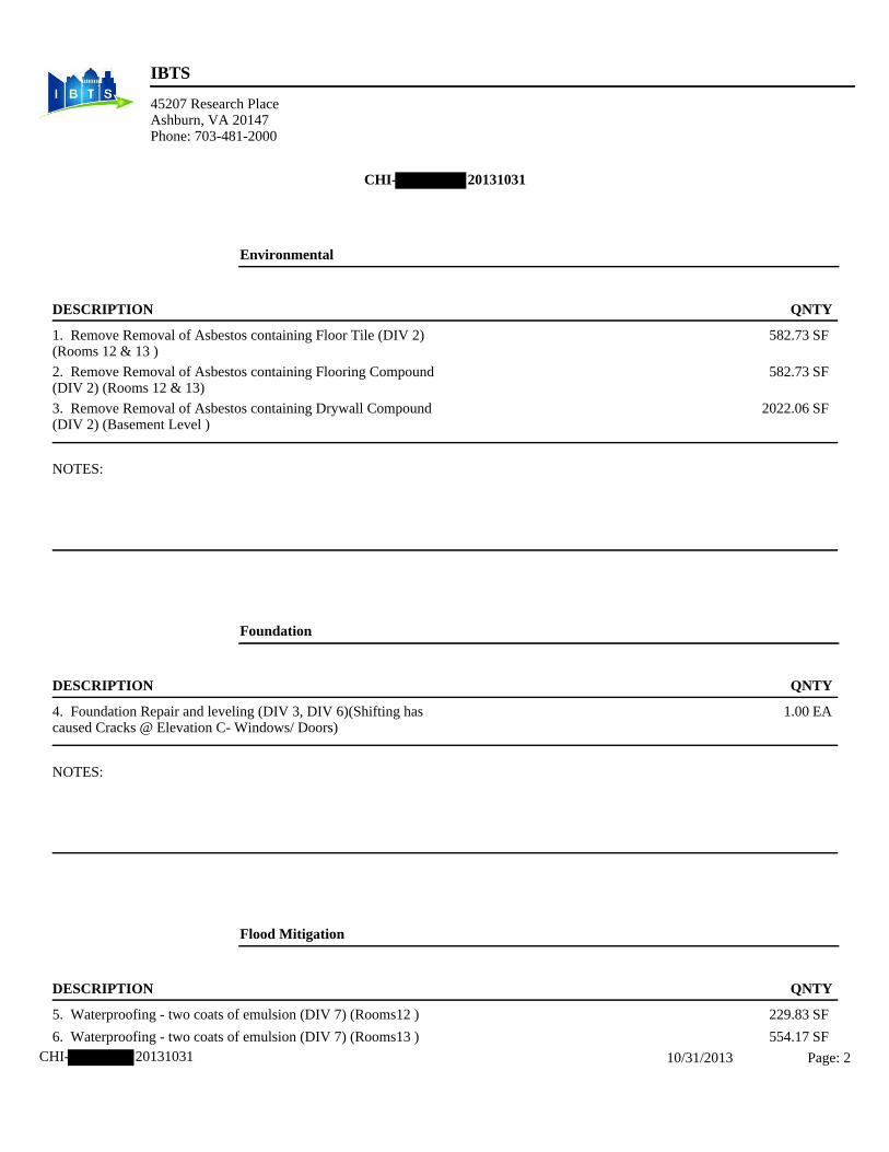
2
IBTS
45207 Research PlaceAshburn, VA 20147Phone: 703-481-2000
CHI- 20131031 10/31/2013 Page: 2
CHI- 20131031
Environmental
DESCRIPTION QNTY
1. Remove Removal of Asbestos containing Floor Tile (DIV 2) 582.73 SF(Rooms 12 & 13 )
2. Remove Removal of Asbestos containing Flooring Compound 582.73 SF(DIV 2) (Rooms 12 & 13)
3. Remove Removal of Asbestos containing Drywall Compound 2022.06 SF(DIV 2) (Basement Level )
NOTES:
Foundation
DESCRIPTION QNTY
4. Foundation Repair and leveling (DIV 3, DIV 6)(Shifting has 1.00 EAcaused Cracks @ Elevation C- Windows/ Doors)
NOTES:
Flood Mitigation
DESCRIPTION QNTY
5. Waterproofing - two coats of emulsion (DIV 7) (Rooms12 ) 229.83 SF
6. Waterproofing - two coats of emulsion (DIV 7) (Rooms13 ) 554.17 SF

3
IBTS
45207 Research PlaceAshburn, VA 20147Phone: 703-481-2000
CHI- 20131031 10/31/2013 Page: 3
CONTINUED - Flood Mitigation
DESCRIPTION QNTY
NOTES:
Electrical
DESCRIPTION QNTY
7. Electrical repair (Test and Inspect) (DIV 16) 1.00 EA
NOTES:
Plumbing
DESCRIPTION QNTY
8. Plumbing repair (Test and Inspect) (DIV 15) 1.00 EA
9. Flood Control System (DIV 15) 1.00 SF
NOTES:

4
IBTS
45207 Research PlaceAshburn, VA 20147Phone: 703-481-2000
CHI- 20131031 10/31/2013 Page: 4
Exterior LxWxH 54' x 26' x 19'
3040.00 SF Walls4444.00 SF Walls & Ceiling156.00 SY Flooring
1026.00 SF Long Wall160.00 LF Ceil. Perimeter
1404.00 SF Ceiling1404.00 SF Floor160.00 LF Floor Perimeter494.00 SF Short Wall
DESCRIPTION QNTY
10. R&R Exterior door - metal - insulated - flush or panel style 2.00 EA(DIV 8)
11. R&R Door lockset & deadbolt - exteriore (DIV 8) 2.00 EA
12. Paint door slab only - 2 coats (per side) (DIV 9) 4.00 EA
13. Paint door/window trim & jamb - 2 coats (per side) (DIV 9) 4.00 EA
14. R&R Vinyl window - double hung, 13-19 sf (DIV 8) (1 on 11.00 EAElevation A, 3 on Elevation C, Several on Elevation B and D,These are boken windows)
NOTES:
Roof
DESCRIPTION QNTY
15. Remove 3 tab - 20 yr. - composition shingle roofing - incl. felt 20.00 SQ(DIV 7)
16. 3 tab - 20 yr. - composition shingle roofing - incl. felt (DIV 7) 22.00 SQ
17. R&R Sheathing - plywood - 1/2" CDX (DIV 6) 2000.00 SF
18. Ice & water shield (DIV 7) 2000.00 SF
NOTES:

5
IBTS
45207 Research PlaceAshburn, VA 20147Phone: 703-481-2000
CHI- 20131031 10/31/2013 Page: 5
Main Level
Kitchen/R1 Height: 8'
428.00 SF Walls603.38 SF Walls & Ceiling19.49 SY Flooring53.50 LF Ceil. Perimeter
175.38 SF Ceiling175.38 SF Floor53.50 LF Floor Perimeter
DESCRIPTION QNTY
19. Carbon monoxide detector (DIV 16) 1.00 EA
NOTES:
Living Room/ R2&3 Height: 8'
652.00 SF Walls1019.88 SF Walls & Ceiling
40.88 SY Flooring81.50 LF Ceil. Perimeter
367.88 SF Ceiling367.88 SF Floor81.50 LF Floor Perimeter
DESCRIPTION QNTY
20. R&R Carpet (DIV 9) 367.88 SF
21. R&R Carpet pad (DIV 9) 367.88 SF
NOTES:

6
IBTS
45207 Research PlaceAshburn, VA 20147Phone: 703-481-2000
CHI- 20131031 10/31/2013 Page: 6
Dining Room/ R3 Height: 8'
376.00 SF Walls514.00 SF Walls & Ceiling15.33 SY Flooring47.00 LF Ceil. Perimeter
138.00 SF Ceiling138.00 SF Floor47.00 LF Floor Perimeter
DESCRIPTION QNTY
22. Remove Ceramic tile (DIV 9) 138.00 SF
23. Tile - vinyl composition (DIV 9) 138.00 SF
24. Floor Leveling Compound (DIV 9) 138.00 SF
NOTES:
Side Entry/R15 Height: 12'
392.00 SF Walls458.00 SF Walls & Ceiling
7.33 SY Flooring32.67 LF Ceil. Perimeter
66.00 SF Ceiling66.00 SF Floor32.67 LF Floor Perimeter
DESCRIPTION QNTY
25. R&R 1/2" drywall - hung, taped, floated, ready for paint (DIV 66.00 SF9) (Ceiling damage)
26. Seal/prime then paint the ceiling (2 coats) (DIV 9) (Ceiling 66.00 SFdamage)
NOTES:

7
IBTS
45207 Research PlaceAshburn, VA 20147Phone: 703-481-2000
CHI- 20131031 10/31/2013 Page: 7
Basement
Laundry Room/ R13 Height: 7'
554.17 SF Walls878.50 SF Walls & Ceiling36.04 SY Flooring79.17 LF Ceil. Perimeter
324.33 SF Ceiling324.33 SF Floor79.17 LF Floor Perimeter
DESCRIPTION QNTY
27. 1/2" water rock - hung, taped, floated, ready for paint (DIV 9) 878.50 SF
28. Seal/prime then paint the walls and ceiling (2 coats) (DIV 9) 878.50 SF
29. R&R Interior door unit - Pre-ung unit (08211) 1.00 EA
30. R&R Door knob - interiore (DIV 8) 1.00 EA
31. Paint door slab only - 2 coats (per side) (DIV 9) 2.00 EA
32. Paint door/window trim & jamb - 2 coats (per side) (DIV 9) 2.00 EA
33. Tile - vinyl composition (DIV 9) 324.33 SF
34. Floor Leveling Compound (DIV 9) 324.33 SF
NOTES:
Basement Room/ R12 Height: 7'
459.67 SF Walls718.06 SF Walls & Ceiling28.71 SY Flooring65.67 LF Ceil. Perimeter
258.40 SF Ceiling258.40 SF Floor65.67 LF Floor Perimeter
DESCRIPTION QNTY
35. Remove Paneling (DIV 6) 459.67 SF
36. 1/2" water rock - hung, taped, floated, ready for paint (DIV 9) 718.06 SF

8
IBTS
45207 Research PlaceAshburn, VA 20147Phone: 703-481-2000
CHI- 20131031 10/31/2013 Page: 8
CONTINUED - Basement Room/ R12
DESCRIPTION QNTY
37. Seal/prime then paint the walls and ceiling (2 coats) (DIV 9) 718.06 SF
38. Tile - vinyl composition (DIV 9) 258.40 SF
39. Floor Leveling Compound (DIV 9) 258.40 SF
NOTES:
Basement Stairs/ R11 Height: 15'
395.00 SF Walls425.50 SF Walls & Ceiling
3.39 SY Flooring26.33 LF Ceil. Perimeter
30.50 SF Ceiling30.50 SF Floor26.33 LF Floor Perimeter
DESCRIPTION QNTY
40. Modify staircase and handrail to conform to local building 1.00 EAcodes (DIV 6)
41. 1/2" water rock - hung, taped, floated, ready for paint (DIV 9) 425.50 SF
42. Seal/prime then paint the walls and ceiling (2 coats) (DIV 9) 425.50 SF
43. Light fixture (DIV 16) 1.00 EA
44. Remove Paneling (DIV 6) 98.75 SF
NOTES:
Half Level

9
IBTS
45207 Research PlaceAshburn, VA 20147Phone: 703-481-2000
CHI- 20131031 10/31/2013 Page: 9
Den/ R10 Height: 8'
797.33 SF Walls1417.92 SF Walls & Ceiling
68.95 SY Flooring99.67 LF Ceil. Perimeter
620.59 SF Ceiling620.59 SF Floor99.67 LF Floor Perimeter
DESCRIPTION QNTY
45. R&R Light fixture (DIV 16) 5.00 EA
46. R&R 1/2" drywall - hung, taped, floated, ready for paint (DIV 620.59 SF9) (Ceiling damage)
47. Seal/prime then paint the ceiling (2 coats) (DIV 9) (Ceiling 620.59 SFdamage)
NOTES:
Stairs/R14 Height: 15'
262.50 SF Walls279.75 SF Walls & Ceiling
1.92 SY Flooring17.50 LF Ceil. Perimeter
17.25 SF Ceiling17.25 SF Floor17.50 LF Floor Perimeter
DESCRIPTION QNTY
48. R&R Carpet (DIV 9) 17.25 SF
49. R&R Carpet pad (DIV 9) 17.25 SF
NOTES:

10
IBTS
45207 Research PlaceAshburn, VA 20147Phone: 703-481-2000
CHI- 20131031 10/31/2013 Page: 10
Bathroom 1/2/ R9 Height: 8'
202.67 SF Walls242.67 SF Walls & Ceiling
4.44 SY Flooring25.33 LF Ceil. Perimeter
40.00 SF Ceiling40.00 SF Floor25.33 LF Floor Perimeter
DESCRIPTION QNTY
50. R&R Interior door unit - Pre-ung unit (08211) 1.00 EA
51. R&R Door knob - interiore (DIV 8) 1.00 EA
52. Paint door slab only - 2 coats (per side) (DIV 9) 2.00 EA
53. Paint door/window trim & jamb - 2 coats (per side) (DIV 9) 2.00 EA
NOTES:
Second Level
Bedroom3(R)/ R8 Height: 8'
362.67 SF Walls489.55 SF Walls & Ceiling14.10 SY Flooring45.33 LF Ceil. Perimeter
126.88 SF Ceiling126.88 SF Floor45.33 LF Floor Perimeter
DESCRIPTION QNTY
54. R&R 1/2" drywall - hung, taped, floated, ready for paint (DIV 217.55 SF9) (Partial walls and all of the ceiling)
55. Seal/prime then paint the walls and ceiling (2 coats) (DIV 9) 489.55 SF
56. R&R Carpet (DIV 9) 126.88 SF
57. R&R Carpet pad (DIV 9) 126.88 SF
58. Remove Light fixture (DIV 16) 1.00 EA
59. Ceiling fan with light (DIV 16) 1.00 EA
60. Smoke detector (DIV 16) 1.00 EA

11
IBTS
45207 Research PlaceAshburn, VA 20147Phone: 703-481-2000
CHI- 20131031 10/31/2013 Page: 11
CONTINUED - Bedroom3(R)/ R8
DESCRIPTION QNTY
NOTES:
Bedroom1(L)/ R6 Height: 8'
438.67 SF Walls622.07 SF Walls & Ceiling20.38 SY Flooring54.83 LF Ceil. Perimeter
183.40 SF Ceiling183.40 SF Floor54.83 LF Floor Perimeter
DESCRIPTION QNTY
61. R&R 1/2" drywall - hung, taped, floated, ready for paint (DIV 402.74 SF9) (Half of the walls and all of the ceiling)
62. Seal/prime then paint the walls and ceiling (2 coats) (DIV 9) 622.07 SF
63. R&R Carpet (DIV 9) 183.40 SF
64. R&R Carpet pad (DIV 9) 183.40 SF
65. Remove Light fixture (DIV 16) 1.00 EA
66. Ceiling fan with light (DIV 16) 1.00 EA
67. Smoke detector (DIV 16) 1.00 EA
NOTES:

12
IBTS
45207 Research PlaceAshburn, VA 20147Phone: 703-481-2000
CHI- 20131031 10/31/2013 Page: 12
Bathroom(Up)/ R5 Height: 8'
281.33 SF Walls358.13 SF Walls & Ceiling
8.53 SY Flooring35.17 LF Ceil. Perimeter
76.79 SF Ceiling76.79 SF Floor35.17 LF Floor Perimeter
DESCRIPTION QNTY
68. R&R 1/2" water rock - hung, taped, floated, ready for paint 70.33 SF(DIV 9)
69. Seal/prime then paint the walls (2 coats) (DIV 9) 281.33 SF
70. R&R Toilet (DIV 15) 1.00 EA
71. R&R Sink - single (DIV 15) 2.00 EA
72. R&R Sink faucet - Bathroom (DIV 15) 2.00 EA
73. Demolish/remove- General (Old/Existing Tub) (DIV 2) 70.00 SF
74. R & R fiberglass tub/shower combo-hardware & fixtures 1.00 EAincluded (DIV 15)
75. ADA Accessories (TAS 4.26) 1.00 EA
NOTES:
Hallway(Up)/ R4 Height: 8'
317.33 SF Walls391.50 SF Walls & Ceiling
8.24 SY Flooring39.67 LF Ceil. Perimeter
74.17 SF Ceiling74.17 SF Floor39.67 LF Floor Perimeter
DESCRIPTION QNTY
76. R&R Carpet (DIV 9) 74.17 SF
77. R&R Carpet pad (DIV 9) 74.17 SF

13
IBTS
45207 Research PlaceAshburn, VA 20147Phone: 703-481-2000
CHI- 20131031 10/31/2013 Page: 13
CONTINUED - Hallway(Up)/ R4
DESCRIPTION QNTY
NOTES:
Grand Total Areas:9,360.67 SF Walls 4,059.94 SF Ceiling SF Walls and Ceiling13,420.604,059.94 SF Floor 451.10 SY Flooring 913.50 LF Floor Perimeter1,026.00 SF Long Wall 494.00 SF Short Wall 913.50 LF Ceil. Perimeter
2,655.94 Floor Area 2,845.63 Total Area 6,320.67 Interior Wall Area4,768.08 Exterior Wall Area 505.67 Exterior Perimeter of
Walls
0.00 Surface Area 0.00 Number of Squares 0.00 Total Perimeter Length0.00 Total Ridge Length 0.00 Total Hip Length

14
CHI- 20131031 10/31/2013 Page: 14
Second Level

15
CHI- 20131031 10/31/2013 Page: 15
Main Level

16
CHI- 20131031 10/31/2013 Page: 16
Half Level

17
CHI- 20131031 10/31/2013 Page: 17
Basement

18
Report Index
10/31/2013 i
Price List And Estimate Info 1 Line Item Detail 2
Grand Total Areas 13 Sketch 14

Limited Asbestos Survey Report Residence Page 1 of 11
Skokie, IL
Limited Asbestos Survey Report
Residence
Skokie, Illinois
Prepared for:
CDM Smith Inc. 125 South Wacker Drive Suite 600
Chicago, Illinois 60606
Prepared by:
Environmental Design International, inc. 33 West Monroe Street
Suite 1825 Chicago, Illinois 60603
(312) 345-1400
EDI Project Number: 1361.026
September 18, 2013
Gary Flentge Patricia Feeley Asbestos Inspector Technical Reviewer IL License 100-03472
#333

Limited Asbestos Survey Report Residence Page 2 of 11
Skokie, IL
TABLE OF CONTENTS
1.0 SUMMARY ......................................................................................................................................................... 3
2.0 GENERAL PROJECT INFORMATION ............................................................................................................ 4
2.1 GENERAL INFORMATION .......................................................................................................................... 4
2.2 AUTHORIZATION AND ACCESS ............................................................................................................... 4
2.3 PURPOSE AND REGULATIONS ................................................................................................................. 4
2.4 WARRANTY AND LIMITATIONS .............................................................................................................. 5
3.0 SCOPE OF SERVICES ........................................................................................................................................ 6
4.0 ASBESTOS SURVEY ......................................................................................................................................... 7
4.1 METHODOLOGY ........................................................................................................................................... 7
4.2 ASBESTOS RESULTS ................................................................................................................................... 7
5.0 FINDINGS AND RECOMMENDATIONS ........................................................................................................ 9
5.1 HAZARD ASSESSMENT ............................................................................................................................... 9
5.2 ASBESTOS HAZARD CATEGORIZATION ..................................................................................................... 10
5.3 PRESUMED ASBESTOS CONTAINING MATERIAL .................................................................................... 11
Appendices
Appendix A Photographs and Sample Log Sheet Appendix B: ACM Drawing, Laboratory Report of Asbestos samples, & Laboratory Certification Appendix C: Inspector License and Certificates Appendix D: Glossary

Limited Asbestos Survey Report Residence Page 3 of 11
Skokie, IL
1.0 SUMMARY
Environmental Design International inc. (EDI) was retained by CDM Smith Inc to conduct a Limited Asbestos Survey in accordance with the United States Environmental Protection Agency (USEPA) Asbestos in Buildings: Simplified Sampling Scheme for Friable Surfacing Materials (USEPA 560/5085-030a, October 1985). This project is part of the Illinois Ike Disaster Recovery Program and is one step in the applicant’s request for disaster relief assistance funding. This project is part of the Damage Assessment. CDM Smith is acting as the IDRP Program Manager on behalf of the State of Illinois. The following summarizes the General Project Information
Residence: Skokie, IL Date of Assessment: August 26 & 29, 2013 Survey performed by: Gary Flentge, Illinois Licensed Asbestos Inspector (100-03472) Report prepared by: Caitlin Ford, EDI Task Manager
This report should be read in its entirety, including detailed information that is contained in other sections and appendices.
The survey included a visual inspection of accessible areas of the house to identify suspect asbestos containing materials (ACM) and identify similar suspect materials into homogenous areas (HAs). The following suspect ACM was identified and sampled: floor tile and mastic, and drywall.
Asbestos was detected below the regulatory level of one percent in samples of the following materials:
White drywall composite had trace asbestos (Throughout)
The drywall composite sample had a trace detection of asbestos. EDI recommends the material be handled as ACM with regards to worker and occupant protection.
Asbestos was detected above the regulatory level of one percent in samples of the following materials:
12”x12” floor tile and associated black mastic, multi-layered (Rooms 12 and 13 ) Joint compound (throughout basement)
This report provides a summary of the results, findings and recommendations, and supporting documentation in the Appendices.

Limited Asbestos Survey Report Residence Page 4 of 11
Skokie, IL
2.0 GENERAL PROJECT INFORMATION
2.1 GENERAL INFORMATION
Applicant: Resident Location: Skokie, IL Date of Assessment: August 26 & 29, 2013 Assessment Performed by: Gary Flentge Data Collected: 6 samples collected and tested by PLM Description/Area of Damage: Flooding damage in the basement.
The property is a single family home, built circa 1967. This report was prepared by Caitlin Ford of Environmental Design International inc (EDI). The Limited Asbestos Survey was conducted following United States Environmental Protection Agency (USEPA) Asbestos in Buildings: Simplified Sampling Scheme for Friable Surfacing Materials (USEPA 560/5085-030a, October 1985); USEPA Asbestos Hazard Emergency Response Act (AHERA); the Illinois Administrative Code Title 77 Section 855 IDPH Notification and Procedures for Abatement of Asbestos in Commercial and Public Buildings; and following our subcontractor agreement with CDM Smith.
2.2 AUTHORIZATION AND ACCESS
Authorization to perform this testing and risk assessment was given by CDM Smith Inc. in the form of an executed Subcontract Agreement. Access to the residence was arranged by IBTS as part of the Damage Assessment.
2.3 PURPOSE AND REGULATIONS
The purpose of the limited asbestos survey is to identify ACM that will need to be abatement prior to renovation. Building materials that contain more than 1% asbestos are considered to be ACM by Federal and State Regulations. Regulated asbestos to be abated prior to demolition is in the form of friable asbestos.
Asbestos removal is regulated in Illinois Administrative Code Title 77 Section 855 IDPH Notification and Procedures for Abatement of Asbestos in Commercial and Public Buildings. Codes of Federal Regulations (CRF) governing asbestos include 29 CFR 1910.1001 OSHA, 29 CFR 1910.20 OSHA General Safety and Health Provisions, and 40 CFR 61 Subpart M National Emissions Standards for Hazardous Air Pollutants (NESHAP) and 40 CFR Part 763 Asbestos.
The NESHAP regulations define asbestos into Category I and II materials and into friable and non-friable categories. Category I material is defined as asbestos-containing resilient floor covering, asphalt roofing products, packings and gaskets. Asbestos-containing mastic is also considered a Category I material (EPA determination - April 9, 1991). Category II material is defined as all

Limited Asbestos Survey Report Residence Page 5 of 11
Skokie, IL
remaining types of non-friable ACM not included in Category I that, when dry, cannot be crumbled, pulverized, or reduced to powder by hand pressure. Nonfriable asbestos-cement products such as transite are an example of Category II material. This information can be found on the EPA website for Region 5 under Air and Asbestos. Examples of Category II or Friable ACM that must be removed prior to building demolition include TSI on piping, drywall and joint compound, transite walls and ceilings, broken floor tile and associated mastic.
2.4 WARRANTY AND LIMITATIONS
The information contained in this report is based upon the data available as of the date of the survey and collected at the residence during the survey by EDI.
These observations and results are time dependent, are subject to changing site conditions, and revisions to Federal, state, and local regulations.
All materials tested are assumed homogeneous throughout the proposed work areas. Every attempt was made to thoroughly evaluate and assess the presence and condition of suspect ACM. EDI did not perform destructive sampling practices and suspect materials may exist within occupied or inaccessible areas. Any suspect material identified during renovation that is not specifically listed herein should be thoroughly assessed, sampled and analyzed prior to disturbance, in accordance with applicable regulatory standards.
The findings and conclusions in this report are not specific certainties; rather they are probabilities based on professional judgment concerning the significance of the data collected. EDI claims to represent only the specific findings documented herein and does not claim knowledge of conditions beyond the scope of the limited survey. The limited asbestos survey was conducted in a manner consistent with that level of care and skill ordinarily exercised by members of the environmental profession under similar conditions. No other warranty or guarantee, express or implied, is included or intended in this Report or otherwise.
The survey and analytical methods have been used to provide the client with information regarding the presence of accessible and/or exposed ACM existing in the facility at the time of survey. Test results are valid only for the material tested. There is a distinct possibility that conditions may exist which could not be identified within the scope of the study or which were not apparent during the site visit. This survey covered only those areas which were exposed and/or physically accessible to the inspector.
EDI also recognizes that laboratory test data are usually not sufficient to make all abatement and management decisions and recommends that EDI be afforded an opportunity to review abatement specification so test results may be properly interpreted and implemented.
This report has been prepared for the exclusive use of the Client for the building at the subject site. It is not intended for the use or benefit of any other party.

Limited Asbestos Survey Report Residence Page 6 of 11
Skokie, IL
3.0 SCOPE OF SERVICES
The scope of services requested by CDM Smith Inc. included the on-site inspection for observed suspect ACM materials and sample collection; sample analysis by PLM at a certified laboratory; and preparation of this report. The report includes project information, inspection photographs of suspect materials sampled, sample analysis and data, findings and recommendations, and signature and qualifications of the inspector.
A list of results by homogenous area is included in the report and the laboratory results are provided in Appendix B of this report. Estimated quantities are provided, however, all materials may not be accessible at the time of the inspection. The scope of construction projects can change. The asbestos inspection report must be reviewed, and untested suspect ACM in the path of construction should be tested, before any work begins. Asbestos hazards are discussed in this report; however, the asbestos survey is not an asbestos abatement design.
Based upon conversations with the applicant/resident and CDM Smith Inc. (Client), to the knowledge of this Inspector, there has not been any previous ACM testing at this home.
Roofing materials are typically not sampled due to concerns about maintaining the integrity of the building envelope, and existing warranties. Samples were collected to be minimally invasive or damaging and to be representative.

Limited Asbestos Survey Report Residence Page 7 of 11
Skokie, IL
4.0 ASBESTOS SURVEY
4.1 METHODOLOGY
The ACM survey was performed in accordance with the United States Environmental Protection Agency (USEPA) Asbestos in Buildings: Simplified Sampling Scheme for Friable Surfacing Materials (USEPA 560/5085-030a, October 1985). Similar building components were grouped into homogenous sampling areas (HAs). HAs are areas containing materials that are similar in color, texture, and general appearance, and which appear to have been uniformly installed during the same time period. The asbestos sampling included interior and exterior building materials, such as floor tiles, pipe insulation, window caulks, and transite. The materials were collected to sample all layers on a building component. The laboratory analyzed multi-layer samples separately. Roofs were generally not sampled.
Bulk samples of suspect ACM were collected using wet sampling methods with a sample cutter, as appropriate, to collect a cross-section of the suspect ACM. Sample collection tools were decontaminated after each sample by washing with soap and water and dried by disposable towels to avoid cross contamination. Bulk ACM samples were placed into clean unused bags marked with a unique sample identification number. For each sample, the identification number, brief material description, location, and estimated quantity of suspect ACM were recorded on a bulk sample log sheet (provided in Appendix A).
Chain-of-Custody (COC) procedures were followed for the ACM survey. These procedures provide a written tracking mechanism that lists the person responsible for the sample from collection to delivery to the laboratory. Sample identification numbers, sample locations, and material descriptions were recorded on the chain-of-custody forms. The COC forms are provided with the laboratory bulk sample log sheet. Sample locations are shown in the drawings in Appendix B.
All samples were analyzed by International Asbestos Testing Laboratories (IATL) in Laurel, New Jersey, a National Voluntary Laboratory Accreditation Program (NVLAP) accredited asbestos laboratory. Bulk samples were analyzed by polarized light microscopy (PLM), utilizing a light microscope equipped with polarized filters (USEPA Method 600/R-93/116). The laboratory report is provided in Appendix B. Current laboratory accreditation is provided in Appendix B.
4.2 ASBESTOS RESULTS
A material is considered by the EPA to be asbestos containing if at least one sample collected from the area shows asbestos present in an amount greater than one percent (>1%). The visual survey identified HAs and below is a list of the suspect materials sampled. Non-suspect materials, such as fiberglass piping wrap, foam rubber, and wood products are identified in the field during the visual survey and not sampled. Photographs of the visual survey and suspect materials are included with Appendix A for review. The asbestos sample log is included in Appendix A.
Samples were collected from the following suspect materials:

Limited Asbestos Survey Report Residence Page 8 of 11
Skokie, IL
o 12”x12” floor tile and black mastic, multi-layered (Rooms 12 and 13, Cl is the closet inroom 12)
o Drywall (Throughout basement)
The samples were submitted under chain of custody to IATL for laboratory analysis of asbestos by PLM. The laboratory report of the analysis results is included in Appendix B with the laboratory certification. A drawing showing the samples collected and the laboratory reported ACM is included in Appendix B.
Asbestos was detected above the regulatory level of one percent in samples of the following materials: 12”x12” floor tile and associated black mastic, multi-layered, (Rooms 12 and 13, Cl ) Joint compound (throughout basement)
Asbestos was detected below the regulatory level of one percent in samples of the following materials:
White drywall composite had trace asbestos (Throughout basement, tested DWTC1-007,008, 009, rooms 12 and 13)
**Special Note on Composite Drywall, Tape and Joint Compound Sampling & Analysis**
Based on composite sampling protocol recognized by EPA for drywall, tape and joint compound, together with an analysis protocol recognized by EPA for composite analysis of a composite sample of drywall, tape and joint compound; it is possible for one of the layered materials that comprise the composite drywall, tape and joint compound sample to be reported as >1% asbestos. When the composite sample is analyzed as a composite material in accordance with the EPA recognized laboratory method, the result may be less that 1%.
Asbestos was detected in one of the layers of the composite drywall, tape and joint compound at >1%, specifically the joint compound at this property. Analysis by EPA-recognized composite analytical method subsequently indicate that the composite drywall, tape and joint compound systems as <1% and/or trace results for asbestos.
EDI recommends the material be handled as ACM with regards to worker and occupant protection.
Any materials identified in any other part of the unit that are similar and homogeneous to those identified as ACM herein, must be handled as ACM.

Limited Asbestos Survey Report Residence Page 9 of 11
Skokie, IL
5.0 FINDINGS AND RECOMMENDATIONS
5.1 HAZARD ASSESSMENT Suspect materials from which samples were collected were assessed and categorized by hazard level. The location and estimated quantity of the material, the condition of the material, accessibility of the material, potential for disturbance, and exposure to air movement, vibration, and water were considered in the assessment.
Based on the described conditions and laboratory analysis results, materials which were sampled were classified into one of the following categories:
Asbestos Hazard Categorization List:
C-1 Asbestos Present - Serious Health Hazard; Abatement should be top
priority C-2 Asbestos Present - Health Hazard; Abatement should be
planned C-3 Asbestos Present - No Action Necessary Unless Renovation,
Remodeling, or Demolition is Planned B-1 Asbestos Present - Contains 1% asbestos, or less
B-2 Asbestos Present - Adequately Enclosed
B-3 Asbestos Present - Adequately Encapsulated
A No Asbestos Found
A-1 Asbestos Abated - Once Identified Asbestos Containing Materials have been
abated.

Limited Asbestos Survey Report Residence Page 10 of 11
Skokie, IL
The Response Action Options for asbestos-containing materials are listed as follows:
Operations and Maintenance The materials are maintained in an undamaged condition and monitored so that the potential for disturbance is minimized. Implementation of an Operations and Maintenance (O & M) Plan involves repair or removal of damaged materials, record keeping, worker training, inspections and air monitoring.
Encapsulation Surfaces of the ACM are sealed with a bridging-type encapsulant or the ACM is rendered non-friable with a penetrating type encapsulant. The material is disturbed during application of this method therefore a controlled work area is required.
Enclosure The materials are isolated behind air-tight barriers such as gyp-board or plywood walls so that they are inaccessible to building occupants. A controlled work area is required for this method so that asbestos does not contaminate the building.
Removal ACM is removed and properly disposed of by a licensed abatement contractor under asbestos control conditions.
5.2 ASBESTOS HAZARD CATEGORIZATION
The following table lists the Asbestos Hazard Categorization, recommended response action, and estimated quantity for the materials identified in the inspection.
Material Location Hazard Category
Recommended Response
Action
Estimated Quantity
AHERA
12”x12” floor tile and
associated black mastic, multi-layered
Rooms 12 and 13
C-3 O&M 700 S.F. 5
Drywall joint compound
Throughout basement
C-3 O&M * 5
*Estimated quantity to be determined by IBTS based on damage assessment.Note:Certain materials such as piping, and multiple layered ceiling applications and floor coveringsmay not be totally visible due to their location behind other materials. Quantities of suchmaterials are estimated. Once affected areas become vacant and appropriateauthorization is obtained, more destructive investigation and quantification may be feasible.
Drawings showing the asbestos by homogenous areas are found in Appendix B.

Limited Asbestos Survey Report Residence Page 11 of 11
Skokie, IL
AHERA CLASSIFICATION
The assessment of asbestos-containing materials by an accredited inspector is required by EPA AHERA regulations (40 CFR 763 Subpart E). The ACM is classified into one of the following categories:
(1) Damaged or significantly damaged thermal system insulation ACM. (2) Damaged friable surfacing ACM. (3) Significantly damaged friable surfacing ACM. (4) Damaged or significantly damaged friable miscellaneous ACM. (5) ACBM with potential for damage. (6) ACBM with potential for significant damage. (7) Any remaining friable ACBM or friable suspected ACBM.
The AHERA classification for the ACM identified in the inspection is presented in the sample summary table in the Appendix.
This Inspection Report is not an Abatement Specification, and should not be used for bidding purposes. Quantities stated herein are approximate, and must be field verified before commencing any abatement activities. An Abatement Specification must be prepared by a Licensed Asbestos Consultant prior to abatement, and all removal must be performed by a licensed Asbestos Contractor.
5.3 PRESUMED ASBESTOS CONTAINING MATERIAL
Building materials such as thermal insulation in pipe chases, multiple layered ceiling applications and floor coverings, and vapor barriers behind exterior facades are typically inaccessible to the inspector, and are therefore assumed to be asbestos-containing. Before commencing renovation or demolition activities the presence of such materials can be investigated, and if found, the asbestos content can be verified by laboratory analysis.

Appendices

I
'iATL INTERNATIONAL ASBESTOS TBS'f.ING LA.UOltATORlES
Client: EDI
9000 Commerce Parkway, Suite B • Mount Laurel, NJ 08054 Phone: 877-428-4285/856-231-9449 • Fax: 856-231-9818
Sample Log -Bulk Asbestos -
Project: ~ 1'63 61fi etd (\ye__
Sampling Datefl'ime:_.......8_..../_Z:_4""""'/...._f.'"-3 _ ___ _ _
Client Samole #
?rlCC~ ;D~lC.t~'l-001
I
J2.J1 - - o<J'f 00.~
oot (.>W\L\ - 00'1
oars '~""'
Bulk Asbest.os SQJple Loe
iATL# Locatfon/Descriotioo l2!'J' 12' ~l.6~~"t-U: MUt...11 .•. !.:~:: .. J • A
""' 1J"U"'-'l "(.Cl • ..JI .. \J(;;I'.--, • \ ' ..,.
_ ... * ..... ~ - ..._
~1H.§t3B,
~}8§i~ ~~ ~\~%1:
. ,. 9'/r/J3 ~ I Jl -
'
Ccletm.t1ing 25 ycors .. • one st1mplc at a time www.iaLl.com
Notes
~ca, l'Z.i\3
'tfr; I, ..
Submltfonn - 2 -

Appendix B

2
CHI- 9/9/2013 Page: 2
Secon Level
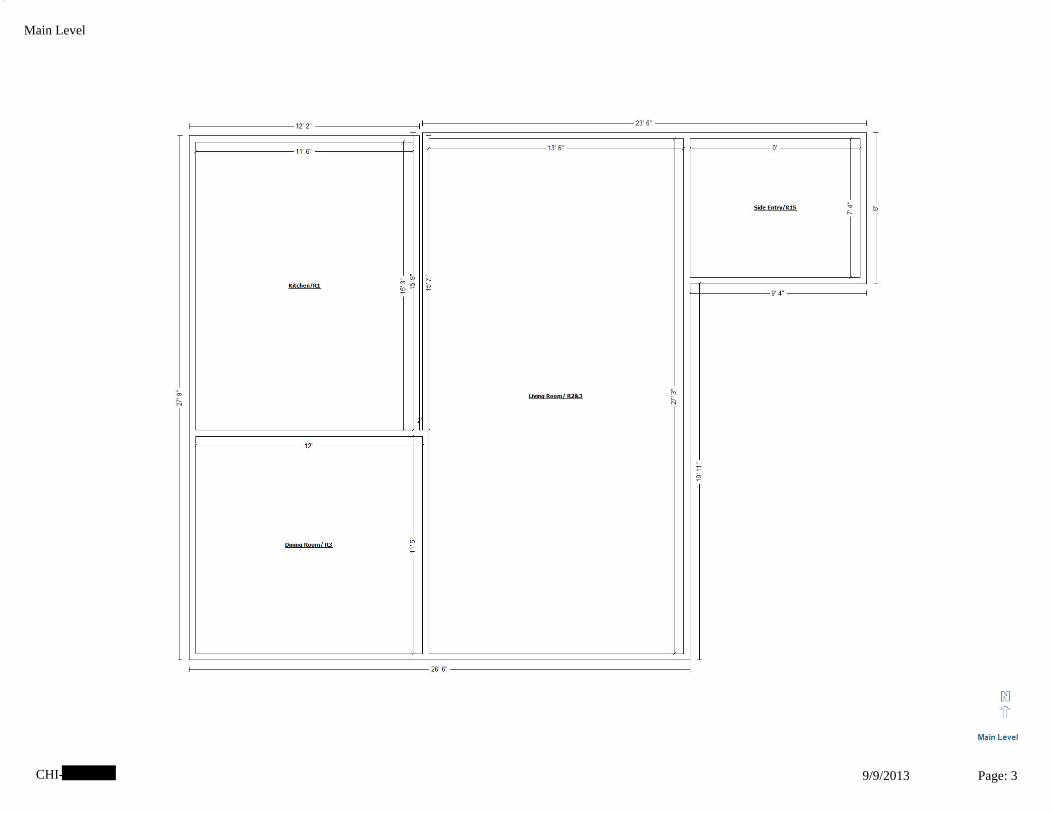
3
CHI- 9/9/2013 Page: 3
Main Level

4
CHI- 9/9/2013 Page: 4
Half Level

5
CHI- 9/9/2013 Page: 5
Basement

Asbestos Samples Results

9000 Commerce Parkway Suite B Mt. Laurel, NJ 08054
Telephone: 856-231-9449 Fax: 856-231-9818
International Asbestos
Testing Laboratories
IATL
CERTIFICATE OF ANALYSIS
(Revised)
Client:
Report Date:
Project No.:
Project:
BULK SAMPLE ANALYSIS SUMMARY
Environ. Design International
33 W Monroe, Suite 1825
Chicago IL 60603
1361.026
9/5/2013
Report No.: 313770
% Asbestos Type % Non-Asbestos Fibrous Material Type % Non-Fibrous Material
Client No.:
Lab No.:
FT1-004
5109129 Description / Location:
Rooms C1, 12, 13
None Detected None Detected 2 Fibrous Glass 98
Tan Floor Tile; 12x12
% Asbestos Type % Non-Asbestos Fibrous Material Type % Non-Fibrous Material
Client No.:
Lab No.:
FT1-004
5109129 Description / Location:
Rooms C1, 12, 13
None Detected None Detected None Detected None Detected 100
Yellow Mastic Layer No.: 2
% Asbestos Type % Non-Asbestos Fibrous Material Type % Non-Fibrous Material
Client No.:
Lab No.:
FT1-004
5109129 Description / Location:
Rooms C1, 12, 13
None Detected None Detected None Detected None Detected 100
Grey Floor Tile Layer No.: 3
% Asbestos Type % Non-Asbestos Fibrous Material Type % Non-Fibrous Material
Client No.:
Lab No.:
FT1-004
5109129 Description / Location:
Rooms C1, 12, 13
None Detected None Detected None Detected None Detected 100
Yellow Mastic Layer No.: 4
NIST-NVLAP No. 101165-0 NY-DOH No. 11021 AIHA-LAP, LLC No. 100188
This confidential report relates only to those item(s) tested and does not represent an endorsement by NIST-NVLAP, AIHA or any agency of the U.S. government
This report shall not be reproduced except in full, without written approval of the laboratory.
EPA 600/R-93/116 By Polarized Light MicroscopyAnalytical Method:
Comments: (PC) Indicates Stratified Point Count Method performed. Method not performed unless stated. Quantification at <0.25% by volume is possible with this method. (PC–Trace) represents
this limit of quantitation. (PC-Trace) means that asbestos was detected but is not quantifiable under the Point Counting regimen. Analysis includes all distinct separable layers in
accordance with EPA 600 Method. If not reported or otherwise noted, layer is either not present or the client has specifically requested that it not be analyzed. Small asbestos fibers may
be missed by PLM due to resolution limitations of the optical microscope. Therefore, negative PLM results cannot be guaranteed. Electron Microscopy can be used as a confirming
technique. Regulatory Limit is based upon the sample matrix.
Analysis Performed By:
Date:
Approved By:
Frank E. Ehrenfeld, III
Laboratory Director
9/5/2013
Page 1 of 8
L. Solebello
_____________________________

9000 Commerce Parkway Suite B Mt. Laurel, NJ 08054
Telephone: 856-231-9449 Fax: 856-231-9818
International Asbestos
Testing Laboratories
IATL
CERTIFICATE OF ANALYSIS
(Revised)
Client:
Report Date:
Project No.:
Project:
BULK SAMPLE ANALYSIS SUMMARY
Environ. Design International
33 W Monroe, Suite 1825
Chicago IL 60603
1361.026
9/5/2013
Report No.: 313770
% Asbestos Type % Non-Asbestos Fibrous Material Type % Non-Fibrous Material
Client No.:
Lab No.:
FT1-004
5109129E Description / Location:
Rooms C1, 12, 13
None Detected None Detected Trace
2
Fibrous Glass
Synthetic
98
Black Floor Tile; 12x12
% Asbestos Type % Non-Asbestos Fibrous Material Type % Non-Fibrous Material
Client No.:
Lab No.:
FT1-004
5109129E Description / Location:
Rooms C1, 12, 13
None Detected None Detected None Detected None Detected 100
Yellow Mastic Layer No.: 2
NIST-NVLAP No. 101165-0 NY-DOH No. 11021 AIHA-LAP, LLC No. 100188
This confidential report relates only to those item(s) tested and does not represent an endorsement by NIST-NVLAP, AIHA or any agency of the U.S. government
This report shall not be reproduced except in full, without written approval of the laboratory.
EPA 600/R-93/116 By Polarized Light MicroscopyAnalytical Method:
Comments: (PC) Indicates Stratified Point Count Method performed. Method not performed unless stated. Quantification at <0.25% by volume is possible with this method. (PC–Trace) represents
this limit of quantitation. (PC-Trace) means that asbestos was detected but is not quantifiable under the Point Counting regimen. Analysis includes all distinct separable layers in
accordance with EPA 600 Method. If not reported or otherwise noted, layer is either not present or the client has specifically requested that it not be analyzed. Small asbestos fibers may
be missed by PLM due to resolution limitations of the optical microscope. Therefore, negative PLM results cannot be guaranteed. Electron Microscopy can be used as a confirming
technique. Regulatory Limit is based upon the sample matrix.
Analysis Performed By:
Date: 9/5/2013
Page 2 of 8
L. Solebello

9000 Commerce Parkway Suite B Mt. Laurel, NJ 08054
Telephone: 856-231-9449 Fax: 856-231-9818
International Asbestos
Testing Laboratories
IATL
CERTIFICATE OF ANALYSIS
(Revised)
Client:
Report Date:
Project No.:
Project:
BULK SAMPLE ANALYSIS SUMMARY
Environ. Design International
33 W Monroe, Suite 1825
Chicago IL 60603
1361.026
9/5/2013
Report No.: 313770
% Asbestos Type % Non-Asbestos Fibrous Material Type % Non-Fibrous Material
Client No.:
Lab No.:
FT1-005
5109130 Description / Location:
Rooms C1, 12, 13
None Detected None Detected Trace Fibrous Glass 100
Lt Tan Floor Tile; 12x12
% Asbestos Type % Non-Asbestos Fibrous Material Type % Non-Fibrous Material
Client No.:
Lab No.:
FT1-005
5109130 Description / Location:
Rooms C1, 12, 13
None Detected None Detected None Detected None Detected 100
Yellow Mastic Layer No.: 2
% Asbestos Type % Non-Asbestos Fibrous Material Type % Non-Fibrous Material
Client No.:
Lab No.:
FT1-005
5109130 Description / Location:
Rooms C1, 12, 13
None Detected None Detected 2 Synthetic 98
Black Floor Tile Layer No.: 3
% Asbestos Type % Non-Asbestos Fibrous Material Type % Non-Fibrous Material
Client No.:
Lab No.:
FT1-005
5109130 Description / Location:
Rooms C1, 12, 13
None Detected None Detected None Detected None Detected 100
Yellow Mastic Layer No.: 4
NIST-NVLAP No. 101165-0 NY-DOH No. 11021 AIHA-LAP, LLC No. 100188
This confidential report relates only to those item(s) tested and does not represent an endorsement by NIST-NVLAP, AIHA or any agency of the U.S. government
This report shall not be reproduced except in full, without written approval of the laboratory.
EPA 600/R-93/116 By Polarized Light MicroscopyAnalytical Method:
Comments: (PC) Indicates Stratified Point Count Method performed. Method not performed unless stated. Quantification at <0.25% by volume is possible with this method. (PC–Trace) represents
this limit of quantitation. (PC-Trace) means that asbestos was detected but is not quantifiable under the Point Counting regimen. Analysis includes all distinct separable layers in
accordance with EPA 600 Method. If not reported or otherwise noted, layer is either not present or the client has specifically requested that it not be analyzed. Small asbestos fibers may
be missed by PLM due to resolution limitations of the optical microscope. Therefore, negative PLM results cannot be guaranteed. Electron Microscopy can be used as a confirming
technique. Regulatory Limit is based upon the sample matrix.
Analysis Performed By:
Date: 9/5/2013
Page 3 of 8
L. Solebello

9000 Commerce Parkway Suite B Mt. Laurel, NJ 08054
Telephone: 856-231-9449 Fax: 856-231-9818
International Asbestos
Testing Laboratories
IATL
CERTIFICATE OF ANALYSIS
(Revised)
Client:
Report Date:
Project No.:
Project:
BULK SAMPLE ANALYSIS SUMMARY
Environ. Design International
33 W Monroe, Suite 1825
Chicago IL 60603
1361.026
9/5/2013
Report No.: 313770
% Asbestos Type % Non-Asbestos Fibrous Material Type % Non-Fibrous Material
Client No.:
Lab No.:
FT1-005
5109130E Description / Location:
Rooms C1, 12, 13
PC 3.7 Chrysotile None Detected None Detected PC 96.3
Brown Floor Tile; 12x12
% Asbestos Type % Non-Asbestos Fibrous Material Type % Non-Fibrous Material
Client No.:
Lab No.:
FT1-005
5109130E Description / Location:
Rooms C1, 12, 13
PC 3.5 Chrysotile None Detected None Detected PC 96.5
Black Mastic Layer No.: 2
NIST-NVLAP No. 101165-0 NY-DOH No. 11021 AIHA-LAP, LLC No. 100188
This confidential report relates only to those item(s) tested and does not represent an endorsement by NIST-NVLAP, AIHA or any agency of the U.S. government
This report shall not be reproduced except in full, without written approval of the laboratory.
EPA 600/R-93/116 By Polarized Light MicroscopyAnalytical Method:
Comments: (PC) Indicates Stratified Point Count Method performed. Method not performed unless stated. Quantification at <0.25% by volume is possible with this method. (PC–Trace) represents
this limit of quantitation. (PC-Trace) means that asbestos was detected but is not quantifiable under the Point Counting regimen. Analysis includes all distinct separable layers in
accordance with EPA 600 Method. If not reported or otherwise noted, layer is either not present or the client has specifically requested that it not be analyzed. Small asbestos fibers may
be missed by PLM due to resolution limitations of the optical microscope. Therefore, negative PLM results cannot be guaranteed. Electron Microscopy can be used as a confirming
technique. Regulatory Limit is based upon the sample matrix.
Analysis Performed By:
Date: 9/5/2013
Page 4 of 8
L. Solebello
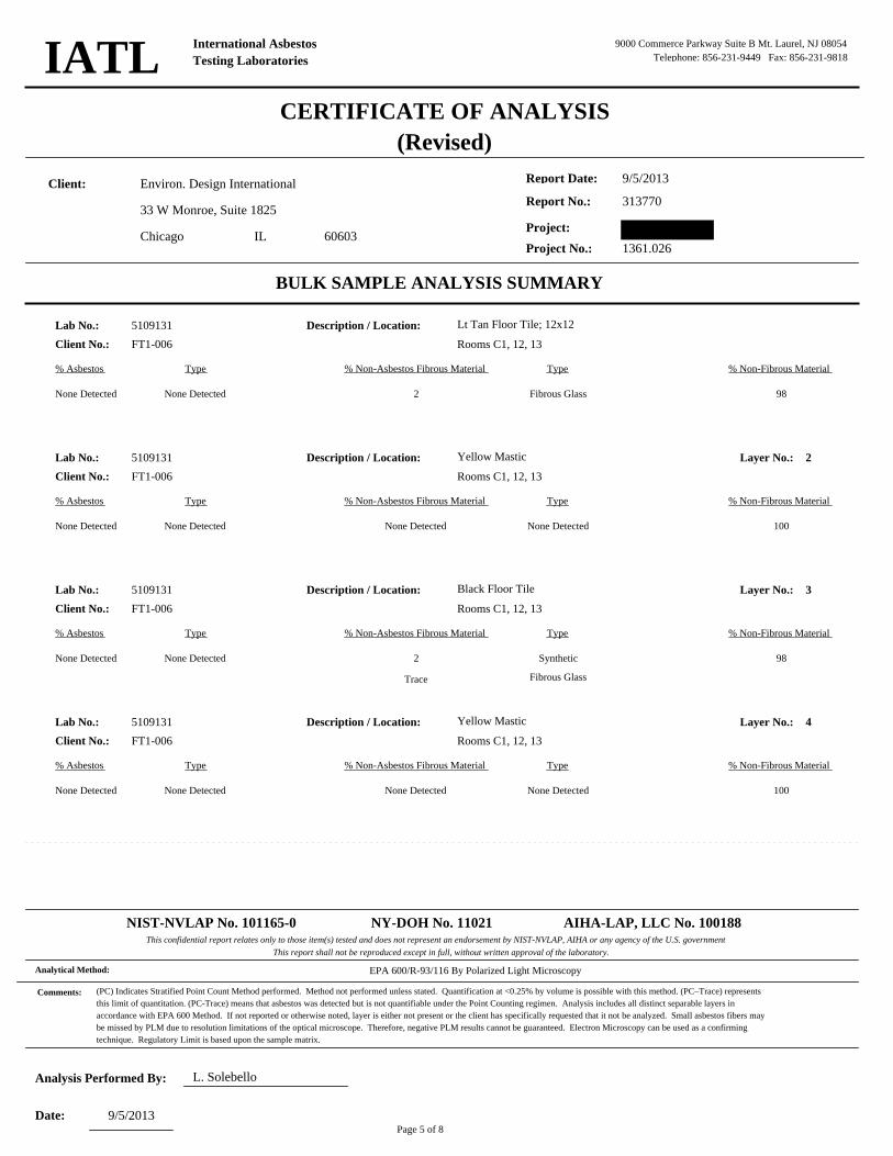
9000 Commerce Parkway Suite B Mt. Laurel, NJ 08054
Telephone: 856-231-9449 Fax: 856-231-9818
International Asbestos
Testing Laboratories
IATL
CERTIFICATE OF ANALYSIS
(Revised)
Client:
Report Date:
Project No.:
Project:
BULK SAMPLE ANALYSIS SUMMARY
Environ. Design International
33 W Monroe, Suite 1825
Chicago IL 60603
1361.026
9/5/2013
Report No.: 313770
% Asbestos Type % Non-Asbestos Fibrous Material Type % Non-Fibrous Material
Client No.:
Lab No.:
FT1-006
5109131 Description / Location:
Rooms C1, 12, 13
None Detected None Detected 2 Fibrous Glass 98
Lt Tan Floor Tile; 12x12
% Asbestos Type % Non-Asbestos Fibrous Material Type % Non-Fibrous Material
Client No.:
Lab No.:
FT1-006
5109131 Description / Location:
Rooms C1, 12, 13
None Detected None Detected None Detected None Detected 100
Yellow Mastic Layer No.: 2
% Asbestos Type % Non-Asbestos Fibrous Material Type % Non-Fibrous Material
Client No.:
Lab No.:
FT1-006
5109131 Description / Location:
Rooms C1, 12, 13
None Detected None Detected 2
Trace
Synthetic
Fibrous Glass
98
Black Floor Tile Layer No.: 3
% Asbestos Type % Non-Asbestos Fibrous Material Type % Non-Fibrous Material
Client No.:
Lab No.:
FT1-006
5109131 Description / Location:
Rooms C1, 12, 13
None Detected None Detected None Detected None Detected 100
Yellow Mastic Layer No.: 4
NIST-NVLAP No. 101165-0 NY-DOH No. 11021 AIHA-LAP, LLC No. 100188
This confidential report relates only to those item(s) tested and does not represent an endorsement by NIST-NVLAP, AIHA or any agency of the U.S. government
This report shall not be reproduced except in full, without written approval of the laboratory.
EPA 600/R-93/116 By Polarized Light MicroscopyAnalytical Method:
Comments: (PC) Indicates Stratified Point Count Method performed. Method not performed unless stated. Quantification at <0.25% by volume is possible with this method. (PC–Trace) represents
this limit of quantitation. (PC-Trace) means that asbestos was detected but is not quantifiable under the Point Counting regimen. Analysis includes all distinct separable layers in
accordance with EPA 600 Method. If not reported or otherwise noted, layer is either not present or the client has specifically requested that it not be analyzed. Small asbestos fibers may
be missed by PLM due to resolution limitations of the optical microscope. Therefore, negative PLM results cannot be guaranteed. Electron Microscopy can be used as a confirming
technique. Regulatory Limit is based upon the sample matrix.
Analysis Performed By:
Date: 9/5/2013
Page 5 of 8
L. Solebello

9000 Commerce Parkway Suite B Mt. Laurel, NJ 08054
Telephone: 856-231-9449 Fax: 856-231-9818
International Asbestos
Testing Laboratories
IATL
CERTIFICATE OF ANALYSIS
(Revised)
Client:
Report Date:
Project No.:
Project:
BULK SAMPLE ANALYSIS SUMMARY
Environ. Design International
33 W Monroe, Suite 1825
Chicago IL 60603
1361.026
9/5/2013
Report No.: 313770
% Asbestos Type % Non-Asbestos Fibrous Material Type % Non-Fibrous Material
Client No.:
Lab No.:
DWTC1-007
5109132 Description / Location:
Throughout
None Detected None Detected 20 Cellulose 80
Off-White/Tan Sheetrock
% Asbestos Type % Non-Asbestos Fibrous Material Type % Non-Fibrous Material
Client No.:
Lab No.:
DWTC1-007
5109132 Description / Location:
Throughout
PC 1.7 Chrysotile None Detected None Detected PC 98.3
Tan Joint Compound Layer No.: 2
% Asbestos Type % Non-Asbestos Fibrous Material Type % Non-Fibrous Material
Client No.:
Lab No.:
DWTC1-007
5109132 Description / Location:
Throughout
PC Trace Chrysotile 20 Cellulose 80
Composite Layer No.: 3
NIST-NVLAP No. 101165-0 NY-DOH No. 11021 AIHA-LAP, LLC No. 100188
This confidential report relates only to those item(s) tested and does not represent an endorsement by NIST-NVLAP, AIHA or any agency of the U.S. government
This report shall not be reproduced except in full, without written approval of the laboratory.
EPA 600/R-93/116 By Polarized Light MicroscopyAnalytical Method:
Comments: (PC) Indicates Stratified Point Count Method performed. Method not performed unless stated. Quantification at <0.25% by volume is possible with this method. (PC–Trace) represents
this limit of quantitation. (PC-Trace) means that asbestos was detected but is not quantifiable under the Point Counting regimen. Analysis includes all distinct separable layers in
accordance with EPA 600 Method. If not reported or otherwise noted, layer is either not present or the client has specifically requested that it not be analyzed. Small asbestos fibers may
be missed by PLM due to resolution limitations of the optical microscope. Therefore, negative PLM results cannot be guaranteed. Electron Microscopy can be used as a confirming
technique. Regulatory Limit is based upon the sample matrix.
Analysis Performed By:
Date: 9/5/2013
Page 6 of 8
L. Solebello

9000 Commerce Parkway Suite B Mt. Laurel, NJ 08054
Telephone: 856-231-9449 Fax: 856-231-9818
International Asbestos
Testing Laboratories
IATL
CERTIFICATE OF ANALYSIS
(Revised)
Client:
Report Date:
Project No.:
Project:
BULK SAMPLE ANALYSIS SUMMARY
Environ. Design International
33 W Monroe, Suite 1825
Chicago IL 60603
1361.026
9/5/2013
Report No.: 313770
% Asbestos Type % Non-Asbestos Fibrous Material Type % Non-Fibrous Material
Client No.:
Lab No.:
DWTC1-008
5109133 Description / Location:
Throughout
None Detected None Detected 15 Cellulose 85
Off-White/Tan Sheetrock
% Asbestos Type % Non-Asbestos Fibrous Material Type % Non-Fibrous Material
Client No.:
Lab No.:
DWTC1-008
5109133 Description / Location:
Throughout
PC 2.0 Chrysotile None Detected None Detected 98
Tan Joint Compound Layer No.: 2
% Asbestos Type % Non-Asbestos Fibrous Material Type % Non-Fibrous Material
Client No.:
Lab No.:
DWTC1-008
5109133 Description / Location:
Throughout
PC Trace Chrysotile 15 Cellulose 85
Composite Layer No.: 3
NIST-NVLAP No. 101165-0 NY-DOH No. 11021 AIHA-LAP, LLC No. 100188
This confidential report relates only to those item(s) tested and does not represent an endorsement by NIST-NVLAP, AIHA or any agency of the U.S. government
This report shall not be reproduced except in full, without written approval of the laboratory.
EPA 600/R-93/116 By Polarized Light MicroscopyAnalytical Method:
Comments: (PC) Indicates Stratified Point Count Method performed. Method not performed unless stated. Quantification at <0.25% by volume is possible with this method. (PC–Trace) represents
this limit of quantitation. (PC-Trace) means that asbestos was detected but is not quantifiable under the Point Counting regimen. Analysis includes all distinct separable layers in
accordance with EPA 600 Method. If not reported or otherwise noted, layer is either not present or the client has specifically requested that it not be analyzed. Small asbestos fibers may
be missed by PLM due to resolution limitations of the optical microscope. Therefore, negative PLM results cannot be guaranteed. Electron Microscopy can be used as a confirming
technique. Regulatory Limit is based upon the sample matrix.
Analysis Performed By:
Date: 9/5/2013
Page 7 of 8
L. Solebello

9000 Commerce Parkway Suite B Mt. Laurel, NJ 08054
Telephone: 856-231-9449 Fax: 856-231-9818
International Asbestos
Testing Laboratories
IATL
CERTIFICATE OF ANALYSIS
(Revised)
Client:
Report Date:
Project No.:
Project:
BULK SAMPLE ANALYSIS SUMMARY
Environ. Design International
33 W Monroe, Suite 1825
Chicago IL 60603
1361.026
9/5/2013
Report No.: 313770
% Asbestos Type % Non-Asbestos Fibrous Material Type % Non-Fibrous Material
Client No.:
Lab No.:
DWTC1-009
5109134 Description / Location:
Throughout
None Detected None Detected 15 Cellulose 85
Off-White/Tan Sheetrock
% Asbestos Type % Non-Asbestos Fibrous Material Type % Non-Fibrous Material
Client No.:
Lab No.:
DWTC1-009
5109134 Description / Location:
Throughout
PC 1.9 Chrysotile None Detected None Detected PC 98.1
Tan Joint Compound Layer No.: 2
% Asbestos Type % Non-Asbestos Fibrous Material Type % Non-Fibrous Material
Client No.:
Lab No.:
DWTC1-009
5109134 Description / Location:
Throughout
PC Trace Chrysotile 15 Cellulose 85
Composite Layer No.: 3
NIST-NVLAP No. 101165-0 NY-DOH No. 11021 AIHA-LAP, LLC No. 100188
This confidential report relates only to those item(s) tested and does not represent an endorsement by NIST-NVLAP, AIHA or any agency of the U.S. government
This report shall not be reproduced except in full, without written approval of the laboratory.
EPA 600/R-93/116 By Polarized Light MicroscopyAnalytical Method:
Comments: (PC) Indicates Stratified Point Count Method performed. Method not performed unless stated. Quantification at <0.25% by volume is possible with this method. (PC–Trace) represents
this limit of quantitation. (PC-Trace) means that asbestos was detected but is not quantifiable under the Point Counting regimen. Analysis includes all distinct separable layers in
accordance with EPA 600 Method. If not reported or otherwise noted, layer is either not present or the client has specifically requested that it not be analyzed. Small asbestos fibers may
be missed by PLM due to resolution limitations of the optical microscope. Therefore, negative PLM results cannot be guaranteed. Electron Microscopy can be used as a confirming
technique. Regulatory Limit is based upon the sample matrix.
Analysis Performed By:
Date: 9/5/2013
Page 8 of 8
L. Solebello

• ''@
tATL 9000 Commerce Parkway, Suite B • Mount Laurel NJ 08054 Phone: 877-428-4285/856-231.-9449 •Fax: 856-231-9818
INTERNATIONAL ASDllS'l.OS 1'ES'11NC LADORATORJP.S
Chain of Custody -Bulk Asbestos -
Cont.act Information ClientC~mpany: _E~O_I~~~~~~~~~- Project Number: 1361.026
Omce Address: 33 W. Monroe Suite 1825 Project Name: City, State, Zip: Chicago, IL 60603 Primary Contact: Patricia Feeley
Fax Number: 312-345-0529 Office Phone: Email Address: [email protected] Cell Phone: 312-445-2400
PLM Instructions: liJ PLM: Bulle Asbestos Building Matorials EPA 600 R-93/1 l 6, 1993 D PLM: BWk Asbestos Building Materials EPA 600 M4/82-020, 1982 0 PLM: Bulk Asbestos Building Materials NIOSH 9002, 1985 D PLM: Bulk Asbestos Building MaterialsNYSDOH-ELAP 198.1, 2002 0 PLM: Eulk Asbestos Building Materials NYSDOH-ELAP 198.6, 2010 0 TEM: Bulk Asbestos Building Materials NYSDOH-BLAP 198.4, 2009
D PLM: Point Counting D PC: via ELAP 198.1 D PC: 4-00 Points 0 PC: 800 Points • D PC; 1600 Points •
[t.s',PLM: Instructions for MuJti~Layered Samples D Analyze and Report All Separable Layers per EPA 600
!B:Jleport Composite for Drywall Systems per NESHAP i'01lcport All Layers and Composite Where Applicable D Only Analyze and Report Specifically Noted Layer
,,.,.,, .. --· .............. ·-·-· .,.- .
/'/
(j).~: Analyze Until Positive (Positive Stop),• /111 AUP: by Homogenous Arca as~<?.!~ .. ,..
D AUP: by Material !¥fJ"'-BS"N6ted LM: NOB viJt.-1·9~ "fllltf:Frl~le via BP A 600 2.3
D If<l% by PLM, to TEMvia 198.4 * D If <1 % by PLM, Hold for Instructions
0 •tt PLM: Non-Building Material ' (Dust, Wipe. Tape) D Soil or Vermiculite Analysis• DCARB435
Speclallnstructfons:~~~~~~~~~~~~~~~~~~~~~~~~~~~~~~~
• A.ddilional charge and IW?Mrowid m.zy be requiml •• Allemall116 Method (ex: EPA 600/R-fH/004) may be reeo1BMended lry La/)Qratory
Turnaround Time Preliminmy Results Requested Date: Dverbe! II Email Iii Fax
S ific date I time D 10 Da.y D 5 Day i 3 Day D 2 Day 0 I Day"' D 12 Hour*• D 6 Hour"'* D RUSH••
"' End of next business day unless otherwise s itied. •• Matrix Dep~dent. 0 *Pleue notify tbe lab before 1bippf,ng*"*
www.1a! l.com ! .. · · Cl. _~ Celebratin.g25 ycars: .. oncsnn:u!lc v:£o: c · · ..
~ ..... ,-- l , . - 1-

I
'iATL 9000 Commerce Parkway, Suite B • Mount Laurel, NJ 08054 Phone: 877-428-4285/856-231-9449 • Fax: 856-231-9818
INTERNATIONAL ASBESTOS TBS'f.ING LA.UOltATORlES
Sample Log -Bulk Asbestos -
Client: EDI Project:
Sampling Datefl'ime:_.......8_..../_Z:_4~/.__f.'"-3 _ ___ _ _
Client Samole #
?rlCC~ ;D~lC.t~'l-001
I
J2.J1 - - o<J'f 00.~
oot (.>W\L\ - 00'1
oars '~""'
Bulk Asbest.os SQJple Loe
iATL# Locatfon/Descriotioo l2!'J' 12' ~l.6~~"t-U: MUt...11 .•. !.:~:: .. J • A
""' 1J"U"'-'l "(.Cl • ..JI .. \J(;;I'.--, • \ ' ..,.
_ ... * ..... ~ - ..._
~1H.§t3B,
~}8§i~ ~~ ~\~%1:
. ,. 9'/r/J3 ~ I Jl -
'
Ccletm.t1ing 25 ycors .. • one st1mplc at a time www.iaLl.com
Notes
~ca, l'Z.i\3
'tfr; I, ..
Submltfonn - 2 -

Occupational Training & Supply, Inc. 7233 Adams Street • Willowbrook, IL 60527 • (630) 655-3900
Gary Flentge has successfully completed the 4 hour Asbestos Building Inspector Refresher Course
and has passed the competency exam with a minimum score of 70%. This course is accredited by the tllinois Department of Public Health and the Indiana Department of Environmental Management for purposes of accreditation in accordance with EPA 40 CFR763, Asbestos Hazard Emergency Response Act (AH ERA) and TSCA Title II. This training course complies with the requirements of TSCA Title II and is accredited by the state of Wisconsin Department of Health Services under CH.DHS159,
Wisconsin Administration Code.
Asbestos Abatement Building Inspector Refresher
Certificate: BIRW/1303080923
Location: 12304 75th Street Kenosha, WI 53143 Issue Date: 3/8/2013 Course Date: 3/8/2013 Examination Date: 3/8/2013 Expiration Date: 3/8/2014

Appendix D

GLOSSARY The following definitions are intended to provide the reader with a better understanding of the terminology used in this report. Asbestos The general name given to a number of naturally occurring hydrated mineral silicates that possess a unique crystalline structure, are incombustible in air, and are separable into fibers. Asbestos includes the asbesti-form varieties of chrysotile (serpentine); corcidolite (riebeckite); amosite (cummingtonite-frunertie); anthopyllite; and actinolite. Asbestos-Containing Material Asbestos contain materials (ACM) are materials that are found to contain greater than one percent by weight asbestos content as determined by polarized light microscopy (PLM) analysis. Accessible Areas An accessible area of the building is any area that the survey team is permitted to inspect and that can be inspected without the disassembly of complicated mechanical or rigid structural components of the building. Examples of accessible areas of the building are interior floors, walls, ceilings, areas above suspended ceilings, return air shafts (normally), mechanical piping exteriors, and equipment exteriors, etc. Damaged material A “damaged” material contains a few water stains or less that one-tenth of insulation with missing jackets and/or crushed insulation or water stains, gouges, punctures, or mars on surface up to one-tenth of the insulation if the damage is evenly distributed or up to one-quarter if the damage is localized. Inaccessible Areas An inaccessible area is any area where inspection access is not permitted or requires a considerable amount of mechanical or structural disassembly to inspect. Inaccessible areas normally only investigated prior to renovation or demolition activities. Examples of inaccessible areas are pipe chases behind walls, mechanically encased insulation, crawlspaces or unsafe areas. Friable Material A material, that when dry, may be crumbled, pulverized or reduced to powder by hand pressure is a friable material. Examples of friable materials include: pipe insulation, boiler or tank insulation, or sprayed-on fireproofing. Non-friable Material A material, that when dry, cannot be crumbled, pulverized or reduced to powder by hand pressure. Non-friable materials may be come friable through damage or deterioration. Examples of non-friable materials include: intact floor tile, transite building panels, or well maintained roofing materials. Homogeneous Area

A homogeneous area is defined as a group of materials that is uniform in texture and appearance, was stalled at one time, and is likely to consist of more than one type or formation of material. Significantly Damaged Material A “significantly damaged” material contains missing jackets on at least one-tenth of the piping or equipment and/or is crushed, heavily gouged, or punctured insulation on at least one-tenth of pipe runs/rises, boilers, tanks, ducts, etc., if the damage is evenly distributed or one-quarter of the damage is localized.

PART VII. IDRP Minimum Housing Rehabilitation Standards
1

ILLINOIS DISASTER RECOVERY PROGRAM
MINIMUM HOUSING REHABILITATION STANDARDS
February 20, 2013 Version 5.0

IDRP Minimum Housing Rehabilitation Standards Part VII - i
PART VII. COOK COUNTY MINIMUM HOUSING REHABILITATION STANDARDS
Table of Contents
I. Preface ................................................................................................................................. 1
II. Definitions ........................................................................................................................... 2
III. Minimum Standards for Basic Equipment and Facilities .............................................. 2
IV. Minimum Standards for Ventilation ................................................................................ 7
V. Minimum Standards for Electrical Service ..................................................................... 8
VI. Minimum Standards for Heating Systems ....................................................................... 9
VII. Minimum Standards for the Interiors of Structures .................................................... 12
VIII. Minimum Standards for the Exterior of Structures .................................................... 13
IX. Minimum Space, Use and Location Requirements ...................................................... 14
X. Minimum Standards for Plumbing Systems ................................................................. 15
XI. Minimum Standards for Potable Water Supply ........................................................... 16
XII. Minimum Standards for Connection to Sanitary Sewer .............................................. 16

IDRP Minimum Housing Rehabilitation Standards Part VII - 1
I. Preface This document is intended to provide the minimum acceptable standards for existing single household dwelling units rehabilitated in whole or in part with the Illinois Disaster Recovery Program (IDRP) Homeowner Repair/Rehabilitation and Reconstruction Program. These standards apply to all communities within Cook County participating in the program. These standards are not intended to reduce or exclude the requirements of any local, county or state building or housing codes, standards, or ordinances that may apply. The IDRP Minimum Housing Rehabilitation Standards are designed to include and to expand on the requirements of the HUD Section 8 Housing Quality Standards (CDBG funded activities) and the Minimum Property Standards (HOME funded activities). Many of the requirements and standards of this document exceed the requirements of the HUD Section 8 Housing Quality Standards and/or the Minimum Property Standards, and are determined necessary to further define the intent or outcome of these standards and to expand on the common definitions of “safe, decent, and sanitary” housing; “non-luxury, suitable amenities” housing; and “good quality, reasonably priced” housing, that is affordable to persons that are low or low and moderate income. These standards are also designed to assist in achieving consistency throughout the county for single-family rehabilitation activities funded by IDRP. Through the IDRP Minimum Housing Rehabilitation Standards, “sustainable design” principles have been incorporated, intended to minimize negative environmental impacts and to promote the health and comfort of the occupants of housing rehabilitated to these standards. Included herein are measures to reduce consumption of non-renewable resources, minimize waste, and to create healthy productive environments. Standard measures have been incorporated herein relating to energy conservation, energy efficiency, water conservation, and indoor air quality. Whenever possible and practical, specify materials or products that are made from recycled materials (such as fly ash concrete, carpeting or flooring made from recycled materials, etc.) or specify materials and products produced from rapidly renewable materials (such as cork or bamboo). To the extent possible and practical, avoid using products from non-renewable resources (such as vinyl siding, windows and flooring; asphalt roofing materials; etc.). These standards assume that a knowledgeable inspector will thoroughly inspect each dwelling to verify the presence and condition of all components, systems and equipment of the dwelling. All components, systems and equipment of a dwelling referenced in this document shall be in good working order and condition and be capable of being used for the purpose in which they were intended and/or designed. Components, systems and/or equipment that are not in good working order and condition shall be repaired or replaced. When it is necessary to replace items (systems, components or equipment), the replacement items must conform to these standards. These standards also assume that the inspector will take into account any extraordinary circumstances of the occupants of the dwelling (e.g., physical disabilities) and reflect a means to address such circumstances in their inspection and in the preparation of a work write-up/project specifications for that dwelling.

IDRP Minimum Housing Rehabilitation Standards Part VII - 2
All interior ceilings, walls and floors must not have any serious defects such as severe bulging or leaning, medium to large holes, loose surface materials, severe buckling, missing components or other serious damage. The roof must be structurally sound and weather-resistant. All exterior walls (including foundation walls) must not have any serious defects such as leaning, buckling, sagging, large holes, or defects that may result in the structure not being weather-resistant or that may result in air infiltration or vermin infestation. The condition of all interior and exterior stairs, halls, porches, walkways, etc. must not present a danger of tripping or falling. Outbuildings must conform to these standards or be removed from the property. If an inspector determines that specific individual standards of this document cannot be achieved on any single dwelling due to it being structurally impossible and/or cost prohibitive, the inspector shall document the specific item(s) as non-conforming with these standards. The inspector shall prepare a list of any and all non-conforming items or non-conforming uses along with his/her recommendation to waive, or not-to-waive, the individual non-conforming items. The inspector’s list of non-conforming items and subsequent recommended actions shall be explained to the property owner and the local official(s) representing the program, as well as provide for their signatures and dating of the inspector’s list of non-conforming items and subsequent recommendations. If all parties (property owner, local officials and inspector) agree, non-conforming items to these standards may be waived. (NOTE: Items that are necessary to meet HUD Section 8 HQS or the Minimum Property Standards may not be waived). II. Definitions
A. Egress – A permanent and unobstructed means of exiting from the dwelling in an emergency escape or rescue situation.
B. Habitable Space (Room) – Space (rooms) within the dwelling for living,
sleeping, eating or cooking. Bathrooms, toilet rooms, closets, halls, storage or utility spaces, and similar areas (rooms) are not considered habitable spaces (rooms).
C. Energy Star Rated – Includes all systems, components, equipment, fixtures and
appliances that meet strict energy efficiency performance criteria established, as a joint effort, by the federal Environmental Protection Agency, the U.S. Department of Energy and the U.S. Department of Housing and Urban Development and that carry the Energy Star label as evidence of meeting these criteria.
III. Minimum Standards for Basic Equipment and Facilities
A. Kitchens – Every dwelling shall have one kitchen room or kitchenette equipped with the following:
1. Kitchen Sink. The dwelling shall have a kitchen sink, connected to both
hot and cold potable water supply lines under pressure and to the sanitary sewer waste line. When replacing such components, water supply shut

IDRP Minimum Housing Rehabilitation Standards Part VII - 3
off valves shall be installed. If the existing faucet is to remain, a 2 gallon per minute (GPM) flow restricting aerator shall be installed.
2. Oven and Stove or Range. The dwelling shall contain an oven and a
stove or range (or microwave oven), supplied by the owner, either gas or electric, connected to the source of fuel or power, in good working order and capable of supplying the service for which it is intended.
3. Refrigerator. The dwelling shall contain a refrigerator, connected to the
power supply, in good working order and capable of supplying the service for which it is intended.
4. Cabinetry and Counter Space Area. Every kitchen or kitchenette shall
have a minimum storage area of eight (8) square feet with a minimum vertical clearance of twelve inches (12”) and a minimum width of twelve inches (12”). Every kitchen or kitchenette shall have a minimum of four (4) square feet of counter space. Each cabinet shall be in safe, decent and sanitary condition.
C. Toilet Room: Every dwelling shall contain a room which is equipped with a
flush toilet and a lavatory. The flush water closet shall be connected to the cold potable water supply, under pressure, and to the sanitary sewer. The lavatory shall be connected to both a hot and cold potable water supply, under pressure, and connected to the sanitary sewer. When replacing such components, water supply shut off valves shall be installed. When replacing toilets, these will have a flush valve that use less than or equal to 1.6 gallons per flush. Toilet throat size will be no less than 2 inches and glazed smooth. If the lavatory faucet is not being replaced then a 2 GPM flow restricting faucet aerator will be installed.
D. Bath Required: Every dwelling shall contain a bathtub and/or shower.
1. The bathtub and/or shower unit(s) need not be located in the same room as
the flush water closet and lavatory. The bathtub and/or shower unit may be located in a separate room.
2. The bathtub and/or shower unit shall be connected to both hot and cold potable water supply lines, under pressure, and shall be connected to the sanitary sewer. All shower heads must be equal to or less than 2.0 GPM water flow. Where feasible, shut off valves shall be installed on the water supply lines. All faucets, when replaced, shall be water balancing scald guard type faucets.

IDRP Minimum Housing Rehabilitation Standards Part VII - 4
E. Privacy in Room(s) Containing Toilet and/or Bath: Every toilet room and/or every bathroom (the room or rooms containing the bathtub and/or shower unit) shall be contained in a room or rooms that afford privacy to a person with said room or rooms.
1. Every toilet room and/or bathroom shall have doors equipped with a
privacy lock or latch in good working order.
F. Hot Water Supply: Every dwelling shall have supplied water-heating equipment (water heater and hot water supply lines) that is free of leaks, connected to the source of fuel or power, and is capable of heating water to be drawn for general usage. 1. No water heaters (except point-of-use water heaters) shall be allowed in
the toilet rooms or bathrooms, bedrooms or sleeping rooms. No gas water heaters shall be allowed in a clothes closet(s).
2. All gas water heaters shall be vented in a safe manner to a chimney or flue
leading to the exterior of the dwelling. Unlined brick chimneys must have a metal B-vent liner installed to meet manufacturer’s venting requirements. If metal chimney venting cannot be added, a power vented water heater may be installed. Size of the B-vent is critical for proper venting. Install according to manufacturer’s recommendations.
3. All water heaters shall be equipped with a pressure/temperature relief
valve possessing a full-sized (non-reduced) rigid copper or steel discharge pipe to within six (6) inches of the floor. The steel discharge pipe shall not be threaded at the discharge end.
4. All water heaters must be installed to manufacturer’s installation
specifications.
5. All new water heaters shall have internal foam insulation that is a minimum of R-10. Gas water heaters shall have an EF rating of .62 or higher and a recovery efficiency of .75 or better and/or meet Energy Star requirements at the time of installation. Electric water heaters shall be Energy Star Rated.
6. Where feasible, tankless water heaters may be installed in accordance with manufacturer’s guidelines and sized to provide adequate hot water supply to all fixtures. Gas supply lines and or electrical capacity must be evaluated before installing tankless water heaters. Before installing, careful consideration should be made regarding supply and water temperature to owners.

IDRP Minimum Housing Rehabilitation Standards Part VII - 5
G. Exits: Every exit from every dwelling shall comply with the following requirements:
1. Every habitable room shall have two (2) independent and unobstructed
means of egress. This is normally achieved through an entrance door and an egress window.
2. All above grade egress windows from habitable rooms shall have a net
clear opening of 5.7 square feet. The minimum net clear opening width dimension shall not be less than twenty inches (20”) wide, and the minimum net clear opening height dimension shall not be less the twenty-four inches (24”) wide. Note that the combination of minimum window width and minimum window height opening size does not meet the 5.7 square feet requirements. Therefore, the window size will need to be greater than the minimum opening sizes in either width or height. Where windows are provided as a means of escape or rescue, they shall have a finished sill height of not more than forty-four inches (44”) above the floor. Egress windows with a finished sill height of more than forty-four inches (44”) shall have a permanently installed step platform that is in compliance with stair construction standards.
All at grade egress windows from habitable rooms may be reduced in size to 5.0 square feet of operable window area, but the area must meet the minimum width and/or and height requirement restrictions of all egress windows.
When windows are being replaced within existing openings, the existing window size shall be determined to be of sufficient size even if current window sizes do not meet current egress standards. However, if the specification writer determines that changing the window size is beneficial; such egress widow size modification will be allowed but not required. If new construction windows are being installed, these windows must meet all egress window requirements.
3. Inhabitable basements (or habitable rooms within a basement) where one
means of egress is a window; the window shall have a net clear opening of 5.70 square feet. The window shall open directly to the street or yard, or where such egress window has a finished sill height that is below the adjacent ground elevation shall have an egress window/area well. The egress window/area well shall provide a minimum accessible net clear opening of nine square feet that includes a minimum horizontal dimension of thirty-six inches (36”) from the window. Egress window/area wells with a depth of more than forty-four (44”) shall be equipped with an affixed ladder or stairs that are accessible with the window in the fully opened position. Such ladder will have rungs at 12 inches on-center and

IDRP Minimum Housing Rehabilitation Standards Part VII - 6
projecting out a minimum of three inches from the side of the window well.
H. Stairs: If tearing out and rebuilding the stairs, the stairs will need to conform to
new construction standards and need to be in compliance with new codes. All newly constructed stairs (interior and exterior stairways) shall comply with the following requirements:
1. All stairways and steps of four (4) or more risers shall have at least one (1)
handrail. All stairways and steps which are three (3) feet or more in width shall have a handrail on each side.
2. All handrails shall be installed not less than thirty four inches (34”) nor
more than thirty-eight inches (38”), measured plumb, above the nosing of the stair treads. Handrails adjacent to a wall shall have a space of not less than one and one-half inches (1 1/2”) between the wall and the handrail. All handrails shall be turned back into the wall on railing ends. The size of a round railing must be a minimum of 1.25 inches, but not more than 2 inches. Railings must be continuous from the top riser to the bottom riser.
3. Porches, balconies or raised floor surfaces, including stairway riser and/or
landing, located more than thirty (30) inches above the floor or the grade, shall have guardrails installed that are not less than thirty-six inches (36”) in height. Open guardrails and stair railings shall have intermediate rails or ornamental pattern such that a sphere four inches (4”) in diameter cannot pass through.
4. All stairs and steps shall have a riser height of not more than eight inches
(8”) and a tread depth of not less than nine inches (9’). All newly constructed stairs, not replacement stairs, shall have a riser height of not more than seven and three quarters (7 3/4”) and a tread depth of not less than ten inches (10”). Risers and treads cannot be different in size by more than 3/8 of an inch from the top to the bottom of the stairs.
I. Smoke Detectors: If smoke detectors are needed and the house is being rewired,
the smoke detectors shall be hard-wired with battery back-up and interconnected with all other alarms. There shall be a minimum of one (1) smoke detector per floor (including the basement) and a smoke detector shall be located adjacent to all bedrooms/sleeping rooms and adjacent to the central heating source. All smoke detectors shall be installed per manufacturer’s installation instructions.
J. Carbon Monoxide Detectors: Where a heating system source, other than solid
fuel burning appliances (e.g., wood stoves), and/or water heater that burns solid, liquid or gaseous fuels is located horizontally adjacent to any habitable room, a hard-wired with battery back-up carbon monoxide detector is required and is to be installed per the manufacturer’s instructions. Any dwelling that has a fuel source

IDRP Minimum Housing Rehabilitation Standards Part VII - 7
heating system (not electric), other solid fuel burning appliances (e.g., wood stoves, pellet, or corn stoves), and/or fuel source water heater (not electric), a hard-wired with battery back-up combination smoke alarm/carbon monoxide detector is required to be installed per the manufacturer’s instructions on the main living area floor.
IV. Minimum Standards for Ventilation
A. In general, sufficient ventilation shall be present to ensure adequate air circulation in the dwelling.
B. Every habitable room shall have at least one (1) exterior operable window. All
operable windows shall be capable of being easily opened and held in an open position by window hardware. All operable exterior windows shall be provided with screens if none exist. Half screens on windows are allowable.
C. Bathrooms, including toilet rooms, shall be provided with a mechanical means of
ventilation that is rated at 50 CFM or greater. Fans shall be ducted to the outside of the dwelling. All bathroom fans will be installed on a 20 minute timer for the fan and a regular switch for the light.
D. Attic Ventilation:
1. When using roof vents without soffit vents and without a ceiling vapor
barrier, sufficient vents shall be used to provide one square foot of free vent area for each one hundred fifty (150) square feet of ceiling area.
2. When using roof vents without soffit vents with a ceiling vapor barrier,
sufficient vents shall be used to provide one square foot of free vent area for each three hundred (300) square feet of ceiling area.
3. When using a combination of roof and soffit vents and no ceiling vapor
barrier, sufficient vents shall be used to provide one square foot of free vent area for each three hundred (300) square feet of ceiling area. Vents shall be installed with no less than fifty percent (50%) nor more than eighty percent (80%) of the total vent area in the roof near the peak with the balance of vents in the soffit.
4. To conserve energy, power roof ventilation systems will be used only as a
method of last resort. Roof ventilation should be accomplished through correctly sized gable vents, ridge vents, and/or roof pod ventilation systems, and soffit vents.

IDRP Minimum Housing Rehabilitation Standards Part VII - 8
V. Minimum Standards for Electrical Service
A. Minimum Electrical Service:
1. Every dwelling unit, at a minimum, shall have a 150 ampere breaker controlled electrical panel. All electrical work shall be in compliance with adopted electrical code requirements in accordance with any local, county or state requirements having jurisdiction. The panel, service mast, etc. shall also be installed to local utility company requirements.
B. Convenience Outlets:
1. Every habitable room within the dwelling shall contain at least four (4)
separate duplex, wall-type electrical outlets. Placement of such outlets shall be on separate walls. All newly installed receptacles shall be grounded duplex receptacles or GFCI protected.
2. All electrical outlets used in bathrooms and toilet rooms, all outlets within
six foot (6’-0”) of a water source (excluding designated simplex equipment circuits for clothes washing machines and sump pumps), outlets located on open porches or breezeways, exterior outlets, outlets located in garages and in non-habitable basements, except those electrical outlets that are dedicated appliance outlets. All kitchen receptacles serving the countertop area shall be ground fault circuit interrupter (GFCI) protected. All exterior receptacles shall be covered by a receptacle cover that when a cord is plugged in, the GFCI outlet will stay covered and protected.
3. All electrical outlets carrying heavy appliance loads (i.e., window air
conditioning units, central air-conditioning units where they exist, refrigerators, freezers, electric stoves, microwaves, clothes washing machines, dish washing machines, electric clothes dryers, furnaces, etc.) shall be simplex receptacles on a separate circuit of the proper amperage and wire size.
4. If the house is be rewired, basements shall have a minimum of one (1)
wall-type electrical outlet for every two hundred (200) square feet, or fraction thereof, of the floor area. Unfinished basements shall have a minimum of one (1) GFCI wall-type electrical receptacle. Such receptacle shall be within 20 feet of the furnace.
5. All accessible knob and tube wiring shall be removed and replaced with
type NM cable (Romex) or as required by code.

IDRP Minimum Housing Rehabilitation Standards Part VII - 9
6. All broken, damaged or nonfunctioning switches or outlets shall be replaced. All fixtures and wiring shall be adequately installed to ensure safety from fire so far as visible components are observed.
7. All missing or broken switch and outlet covers (including junction boxes)
shall be replaced. Each receptacle or switch located on an exterior wall shall have a foam seal placed under the cover.
C. Lighting:
1. Every habitable room and every bathroom (including toilet room), laundry
room, furnace or utility room, and hallway shall have at least one (1) ceiling or wall-type electric light fixture, controlled by a remote wall switch. Habitable rooms (except kitchens or kitchenettes) may have a wall-type electrical outlet controlled by a remote wall switch in lieu of a ceiling or wall-type light fixture. Energy efficient fixtures that meet energy star ratings and compact florescent bulbs shall be installed in all new fixture instillations.
2. Basements with no habitable rooms shall have a light illuminating the
stairs with a switch controlling the light located at the top of the stairs. Basements with habitable rooms shall have at least one light fixture controlled by a remote wall switch at the top and bottom of the stairs. If new fixtures are being installed, Energy Star rated fixtures shall be installed with compact florescent bulbs.
3. Porcelain type fixtures with pull chains are acceptable for use in
basements (except for the one controlled by a remote wall switch) basements, and attics.
4. All pendant type lighting fixtures that are supported only by the electrical
supply wire shall be removed or replaced. If replaced, replace with Energy Star rated fixtures.
5. All existing closet lights shall be covered.
VI. Minimum Standards for Heating Systems
A. Heating System: All heating systems (and central air-conditioning systems where they exist) shall be capable of safely and adequately heating (or cooling as applicable) for all living space.
B. Cooling System: Non-working or improperly functioning central air
conditioning systems may be replaced as part of the rehabilitation work. The installation of a central air conditioning system, where it currently does not exist, is not allowable unless medically necessary.

IDRP Minimum Housing Rehabilitation Standards Part VII - 10
C. Requirements for Heating and or Cooling Systems:
1. All existing heating systems, including but not limited to, chimneys and
flues, cut-off valves and switches, limit controls, heat exchangers, burners, combustion and ventilation air, relief valves, drip legs and air, hot water, or steam delivery components (ducts, piping, etc.) that are not being replaced, shall be inspected to be in a safe and proper functioning condition at the time of inspection, by means of written project file documentation.
2. Every heating system burning solid, liquid or gaseous fuels shall be vented
in a safe manner to a chimney or flue leading to the exterior of the dwelling. The heating system chimney and/or flue shall be of such design to assure proper draft and shall be adequately supported.
3. No heating system source burning solid, liquid or gaseous fuels shall be
located in any habitable room or bathroom, including any toilet room. 4. Every fuel burning appliance (solid, liquid or gaseous fuels) shall have
adequate combustion air and ventilation air. All new furnaces will have sealed combustion with combustion air brought in from the exterior of the house and installed in accordance with manufacturer’s guidelines.
5. Every heat duct, steam pipe and hot water pipe shall be free of leaks and
shall function such that an adequate amount of heat is delivered where intended. All accessible duct joints must be sealed with mastic or any other acceptable product. Newly installed ductwork must also be sealed. All accessible steam piping and hot water piping must be installed with an approved material.
6. Every seal between any of the sections of the heating source(s) shall be
air-tight so that noxious gases and fumes will not escape into the dwelling.
7. No space heater shall be of a portable type.
8. Minimum requirements for the heating units, when installed, will be no less than a 92% AFUE, or the minimum AFUE, if greater than 92%, to obtain a local utility rebate (Energy Star rated for Northern climates). The Standard BTU will be 45-50 BTU/sq. ft. Also install a digital programmable thermostat. Condensate lines will drain to a floor drain or have a condensate pump installed and piped to discharge. All furnace duct work shall be equipped with an air filter clean out location that has a tight fitting cover installed over it.

IDRP Minimum Housing Rehabilitation Standards Part VII - 11
9. All boilers, when replaced, will have an “A” rating and be no less than 87% AFUE rating rebate (Energy Star rated for Northern climates). All combustion air will be from the exterior of the house. The addition of zone valves may be useful to reduce energy cost. Heat lines shall be insulated with approved material. Programmable thermostats will be installed.
10. A/C units, if added or replaced, shall not be less than 14 SEER or the lowest SEER rating that is available at the time of installation but not less than 14 SEER. All units shall be installed, when possible, on either the north or east side of the dwelling or in an area that will provide shade for the unit. The correct coil will be installed that is compatible with both the furnace and A/C unit.
No window A/C units may be purchased.
11. All wood, pellet, corn, switch grass, hydrogen, or other biomass fuel stoves must be installed to manufacturer’s guidelines. Where such guidelines are not available, the heating unit will be removed. Venting and combustion air must be installed in accordance with manufacturer’s requirements.
D. Energy Conservation
1. All structures shall comply with certain energy conservation measures
(U.S. Department of Energy recommendations). These measures include, but are not necessarily limited to, the following:
a. The provision of insulation at various locations and at the
following recommended resistance factors (r-values). Insulation shall be primarily made from recycled glass or newspaper when available.
i. Ceilings – R-49 for uninsulated attic spaces and R-38 or as
close as possible to these requirements where sloped ceilings exist.
ii. Crawl Spaces (floors or walls) – R-25 iii. Band Joists – R–25 iv. Basement walls – R-13
b. When siding is being replaced and/or interior wall finishes of
exterior walls are being replaced on a dwelling, such exterior walls are to be provided with insulation and at the recommended resistance factor (R-value) of R-20, or that which is allowed by the stud cavity space. In addition, an air infiltration barrier, such as Tyvek or approved equal, shall be installed on all exterior walls. If

IDRP Minimum Housing Rehabilitation Standards Part VII - 12
new walls are being framed and insulated, the minimum R factor is R-20 or R-13 plus R-5 foam. The installation of fan-fold foam or foam sheathing may be added to increase household R-ratings.
c. The installation of weather stripping at all exterior doors, windows,
ground-entry basement doors, etc. is required. Doors, when replaced shall be a metal clad insulated door (Energy Star rated for Northern climates). Storm doors are encouraged, but not required. Door jams will be sealed and thresholds will be caulked.
d. The provision of caulking around exterior doors and windows, at
the foundation/sill plate union, and at other air-infiltration areas.
e. Windows must be current Energy Star rated for Northern climate to obtain local window rebates. All storm windows will be removed from heated areas of the home when windows are replaced. All rope weight openings will be insulated and all new windows will have the window jamb sealed. Where SHPO requirements will restrict the installation of vinyl windows, the specifications will be written to come as close as possible to achieving Energy Star requirements.
f. All heat ducts and hot water or steam heat distribution piping shall
be insulated or otherwise protected from heat loss where such ducts or piping runs are located in unheated spaces. Similarly, distribution piping for general use hot water shall also be protected from heat loss where such piping is located in unheated spaces. All water distribution piping shall be protected from freezing.
g. Attic access passage ways (scuttle holes) shall be no less than 22”
by 30” or the size of original construction. If it is impossible to conform to this standard, the largest attic access hole possible will be installed. Scuttle holes shall extend up a minimum 14 inches above the ceiling. Weather stripping shall be installed at the top of this 14 inch scuttle hole extension and shall be covered with ¾ inch plywood or OSB covered by 2 inch, R-10, foam. The gypsum opening on the ceiling will also be weather stripped and covered with 4 inches of foam. Both doors will be made to sit tight against the weather stripping.
VII. Minimum Standards for the Interiors of Structures
A. Interior Walls, Floors, Ceilings, Doors and Windows:
1. All interior walls, floors, ceilings, doors and windows shall be capable of being kept in a clean and sanitary condition by the owner.

IDRP Minimum Housing Rehabilitation Standards Part VII - 13
2. Every bathroom and/or toilet room, kitchen or kitchenette, and utility
room floor surface shall be constructed such that they are impervious to water and can easily be kept in a clean and sanitary condition by the owner.
3. All interior doors shall be capable of affording the privacy for which they
are intended.
4. The dwelling must have at least one bedroom or living/sleeping room for each two persons. Children of the opposite sex, other than very young children, may not be required to occupy the same bedroom or living/sleeping room.
5. No dwelling containing two or more bedrooms shall have a room
arrangement that access to a bathroom, toilet room, or a bedroom can be achieved only by going through another bathroom, toilet room, or another bedroom.
6. All paints, stains, varnishes, lacquers and other finishes used in the
rehabilitated dwelling shall be low or no VOC paint finishes and installed as required by the manufacture.
VIII. Minimum Standards for the Exterior of Structures
A. Foundations, Exterior Walls, Roofs, Soffits and Fascia:
1. Every foundation, exterior wall, roof, soffit and fascia shall be made weather resistant. Products for exterior walls, roofs, soffits, and fascia shall be installed in accordance with the manufacturer’s guidelines.
2. Roof replacement shall be installed in accordance with the manufacturer’s
requirements. When installing asphalt or fiberglass shingles, a minimum of a 30 year shingle shall be used. Other products such as metal roofing may be considered.
B. Drainage:
1. All rainwater shall be conveyed and drained away from every roof so as
not to cause wetness or dampness in the structure. No roof drainage systems shall be connected to a sanitary sewer.
2. The ground around the dwelling shall be sloped away from foundation
walls to divert water away from the structure. 3. If feasible, the collection of roof water is encouraged.

IDRP Minimum Housing Rehabilitation Standards Part VII - 14
C. Windows, Exterior Doors and Basement Entries (Including Hatchways):
1. Every window, exterior door, basement entry and hatchway shall be tight fitting within their frames, be rodent-proof, insect-proof and be weatherproof such that water and surface drainage is prevented from entering the dwelling. In addition, the following requirements shall also be met:
a. All exterior doors and windows shall be equipped with security
locks. Deadbolts are not required.
b. Every window sash shall be fully equipped with glass window panes which are without cracks or holes. Every window sash to be replaced shall use Energy Star rated for Northern climate windows unless the existing windows have insulated glass. Stained or leaded glass found to be historically significant may be protected by a fixed low-E glass storm window. Every window sash shall fit tightly within its frame, and be secured in a manner consistent with the window design. All window jambs will be sealed. All rope weight openings shall be insulated before installing the new window. Energy Star rated for Northern climate.
c. Storm doors, when installed, shall also be equipped with a self-
closing device. d. Every exterior door, when closed, shall fit properly within its
frame and shall have door hinges and security locks or latches. All exterior doors will be no less than metal clad insulated (foam filled) doors. All jambs and thresholds will be sealed.
e. Every exterior door shall be not less than two foot-four inches (2’-
4”) in width and not less than six foot-six inches (6’6”) in height. Existing door sizes will be grandfathered, but an attempt shall be made to have at least one exterior door that is not less than 36 inches wide and no less than 6’-8” high.
IX. Minimum Space, Use and Location Requirements
A. No main floor habitable room in a dwelling shall have a ceiling height of less than seven feet, six inches (7’6”). At least one-half of the floor area of every habitable room located above the first floor shall have a minimum ceiling height of seven feet (7’-0”). The floor area of any room where the ceiling height is less than four feet in height shall not be considered floor area in computing the total floor area of the room.

IDRP Minimum Housing Rehabilitation Standards Part VII - 15
B. A minimum ceiling height of seven feet (7’-0”) is acceptable in bathrooms, toilet
rooms, habitable basement space, and hallways.
C. All habitable rooms, except kitchens and/or kitchenettes, shall have a minimum width of seven feet (7’).
D. No basement space shall be converted to habitable space. E. Habitable Basement Space: No basement space shall be used as habitable space
unless the space is necessary to alleviate overcrowding as required by HQS. The following requirements must be met:
1. The floor and walls are waterproof or damp proof construction.
2. Such habitable space has a hard surfaced floor of concrete or masonry.
3. Such space shall have a minimum of two exits. In addition to the stairs,
this would normally consist of one egress window. 4. An exception may be made on a case by case basis if the basement was
previously a habitable area and will be assessed as a completed basement. X. Minimum Standards for Plumbing Systems
F. All dwelling plumbing systems shall be capable of safely and adequately providing a water supply and wastewater disposal for all plumbing fixtures. Every dwelling plumbing system shall comply with the following requirements.
1. All existing plumbing systems and plumbing system components shall be
free of leaks. When repairing or adding to such systems, any type of pipe allowed by the plumbing code shall be allowed in accordance with any local, county or state requirements having jurisdiction.
2. All plumbing system piping shall be of adequate size to deliver water to
plumbing fixtures and to convey wastewater from plumbing fixtures (including proper slope of wastewater piping) as designed by the fixture manufacturer).
3. All plumbing fixtures shall be in good condition, free of cracks and
defects, and capable of being used for the purpose in which they were intended.
4. The plumbing system shall be vented in a manner that allows the
wastewater system to function at atmospheric pressure and prevents the
IDRP Minimum Housing Rehabilitation Standards Part VII - 16
siphoning of water from fixtures. Venting by mechanical vents is accepted as an alternative to exterior atmospheric venting.
5. All fixtures that discharge wastewater shall contain, or be discharged
through, a trap that prevents the entry of sewer gas into the dwelling.
6. All plumbing system piping and fixtures shall be installed in a manner that prevents the system, or any component of the system, from freezing.
7. All plumbing fixtures and water connections shall be installed in such a
way as to prevent the backflow of water from the system into the plumbing system’s water source.
8. All faucets shall have aerators that restrict water flow to about 2 GPM.
Toilets, when installed, shall only use 1.6 gallons per flush, or less. 9. Valves shall be installed with the valve in the upright position. When
replacing valves, the use of a full port ball-valve shall be encouraged.
XI. Minimum Standards for Potable Water Supply
A. Every dwelling shall be connected to an approved (by the jurisdiction having authority) potable water source.
B. All potable water fixtures and equipment shall be installed in such a manner as to
make it impossible for used, unclean, polluted or contaminated water, mixtures or substances to enter any portion of the potable water system piping. All equipment and fixtures shall be installed with air gaps (traps) to prevent back siphon age. All outlets with hose threads (except those serving a clothes washing machine) shall have a vacuum breaker for use with the application. No water piping supplied by a private water supply system shall be connected to any other source of water supply without the approval of the jurisdiction having authority over the installation.
C. All unused wells on the property shall be abandoned and plugged in accordance
with any local, county or state requirements having jurisdiction. All cisterns shall be drained and filled, and if applicable, in accordance with any local or county requirements having jurisdiction.
XII. Minimum Standards for Connection to Sanitary Sewer
A. Every dwelling shall be connected to an approved (by the jurisdiction having authority) sanitary sewer system or properly operating septic system.

PART VIII. IDRP CONTRACTOR SPECIFICATIONS AND PERFORMANCE MANUAL
IDRP IDRP Contractor Specifications and Performance Manual Part VIII - 1

ILLINOIS DISASTER RECOVERY PROGRAM
CONTRACTOR SPECIFICATIONS AND PERFORMANCE MANUAL
March 19, 2013 VERSION 5.0
IDRP IDRP Contractor Specifications and Performance Manual Part VIII - 2

TABLE OF CONTENTS PART 1: INTRODUCTION Purpose of Contractor Specifications and Performance Manual Material and Workmanship Lead-Based Paint and Asbestos Containing Materials Abatement Historic Rehabilitation PART 2: TECHNICAL REQUIREMENTS DIVISION 1 – GENERAL REQUIREMENTS SECTION 01300 SUBMITTALS DIVISION 2 – SITE WORK SECTION 02000 CLEAN-UP SECTION 02221 DEMOLITION SECTION 02222 MOLD AND REMEDIATION DIVISION 3 – CONCRETE SECTION 03205 CONCRETE SECTION 03119 INSULATING CONCRETE FORMS DIVISION 4 – MASONRY SECTION 04501 MASONRY RESTORATION AND CLEANING DIVISION 6 - WOOD AND PLASTICS SECTION 06100 ROUGH CARPENTRY SECTION 06200 FINISH CARPENTRY SECTION 06400 INTERIOR ARCHITECTURAL WOODWORK DIVISION 7 - THERMAL AND MOISTURE PROTECTION SECTION 07140 FLUID APPLIED WATERPROOFING SECTION 07210 BUILDING INSULATION SECTION 07311 ASPHALT SHINGLES SECTION 07460 SIDING SECTION 07511 BUILT-UP ASPHALT ROOFING SECTION 07550 MODIFIED BITUMINOUS MEMBRANE ROOFING SECTION 07712 GUTTERS AND DOWNSPOUTS DIVISION 8 - DOORS AND WINDOWS SECTION 08211 DOORS SECTION 08550 WINDOWS
IDRP IDRP Contractor Specifications and Performance Manual Part VIII - 3

IDRP IDRP Contractor Specifications and Performance Manual Part VIII - 4
DIVISION 9 - FINISHES SECTION 09210 GYPSUM PLASTER SECTION 09260 GYPSUM BOARD SECTION 09310 CERAMIC TILE SECTION 09650 RESILIENT TILE FLOORING SECTION 09680 CARPET SECTION 09912 PAINT DIVISION 10 – SPECIALTIES SECTION 10747 WINDOW WELLS SECTION 10801 BATH ACCESSORIES DIVISION 14 – CONVEYING EQUIPMENT SECTION 14410 LIFTS DIVISION 15 – MECHANICAL SECTION 15100 HEATING VENTILATION AND AIR CONDITIONING SECTION 15410 PLUMBING DIVISION 16 - ELECTRICAL SECTION 16100 ELECTRICAL SECTION 16511 LIGHTING SECTION 16600 RESIDENTIAL APPLIANCES Appendix A Asbestos Abatement Project Manual General Requirements. Appendix B Historic Rehabilitation

Part 1 - Introduction Purpose of Contractor Specifications and Performance Manual The purpose of the Contractor Specifications and Performance Manual is to provide and make a part of each contract, subcontract and contract bid certain minimum standards of quality of workmanship and materials expected in the Work and required by the STATE, as well as certain contractual obligations expected in the performance of Work under the Program. It is intended that these minimum specifications shall prevail except when in conflict with, or less stringent than the local governments of Skokie, Niles, Maywood, Bellwood, and Glenwood, State, or Federal Regulations or Codes, in which instance the more stringent standards will prevail. The Contractor Specifications and Performance Manual are set forth as a guideline for contractors. Where a direct conflict exists between a provision of the Contractor Specifications and Performance Manual and a provision of a separate Contract Document on a Project, the specific Contract Document shall control. Otherwise, the provisions of the Contractor Specifications and Performance Manual shall be deemed to supplement the contractual requirements. While the STATE, through IDRP, has undertaken due diligence in creating the Contractor Specifications and Performance Manual, the STATE, through IDRP, reserves the right to make changes as deemed necessary. Contractors selected to rehabilitate homes within the STATE for the Program will be notified of any changes to the Contractor Specifications and Performance Manual in writing. All changes become effective immediately upon receipt. Any questions or concerns regarding applicable changes must be submitted in writing to the Housing Manager, IDRP Office within 24 hours of notification. The Contractor Specifications and Performance Manual is specifically designed to serve as a guide for the Rehabilitation and Reconstruction of residences for low to moderate income homeowners residing in Cook County area, including all local governments and cities. Materials and Workmanship All work shall be performed by competent workman pursuant to cost estimates and/or bid documents under the supervision of the CONTRACTOR or his agent. All sizes and grades of materials shall be new, of a generally acceptable standard and in first class condition. All finished work shall be clean and free from tool marks or other foreign blemishes. All measurements shall be verified at building site. All work shall be in conformity with manufacturer’s printed directions. All fittings, off-sets, etc. required shall be furnished and installed without additional expense to HOMEOWNER. All work and supplies shall be protected from the weather during the course of construction. Under no circumstances whatsoever shall CONTRACTOR install any materials supplied by the HOMEOWNER.
Lead-Based Paint and Asbestos Containing Materials Abatement
As outlined in the Work Write Ups, the CONTRACTOR shall be required to complete Lead-Based Paint and Asbestos Containing Materials Abatement in accordance with all local, State and Federal Regulations and Codes. Refer to Appendix A for the Asbestos Abatement Project Manual General Requirements.
IDRP IDRP Contractor Specifications and Performance Manual Part VIII - 5

Historic Preservation If any Historic Properties are identified in Part II - General Construction Matters, the CONTRACTOR shall comply with the all historic preservation requirements including those identified in Part II. Additional, historic rehabilitation and building element specifications are outlined in Appendix B. In the event of any conflict between the requirements, the requirements imposed by the Illinois Historic Preservation Association shall control.
IDRP IDRP Contractor Specifications and Performance Manual Part VIII - 6

Part 2 – Technical Requirements
IDRP IDRP Contractor Specifications and Performance Manual Part VIII - 7

IDRP IDRP Contractor Specifications and Performance Manual Part VIII - 8
DIVISION 1 - GENERAL REQUIREMENTS

SECTION 01300 SUBMITTALS
SECTION 01300
SUBMITTALS
PART 1 GENERAL
1.01 SCOPE OF WORK
A. This Section includes the requirements for compiling, processing and transmitting submittals required for execution of the project.
B. Submittals are categorized into two types: Action Submittals and Informational Submittals, as follows:
1. Action Submittal: Written and graphic information submitted by the Contractor that requires IDRP's approval. The following are examples of action submittals: a. Shop drawings (including working drawings and product data) b. Schedule of values
2. Informational Submittal: Information submitted by the Contractor that does not require the IDRP's approval. The following are examples of informational submittals: a. Shop drawing schedule b. Construction schedule c. Contract close-out documents
1.02 RELATED WORK
A. Additional requirements may be specified in the General Conditions for the Contract.
B. Additional submittal requirements may be specified in the respective technical Specification Sections.
1.03 CONTRACTOR'S RESPONSIBILITIES
A. All submittals shall be clearly identified as follows:
1. Date of submission
2. Project number
3. Project name
4. Contractor identification a. Contractor b. Supplier c. Manufacturer d. Manufacturer or supplier representative
IDRP IDRP Contractor Specifications and Performance Manual Part VIII - 9

SECTION 01300 SUBMITTALS
5. Identification of the product
6. Reference to Work Write-up
7. Reference to specification section number, page and paragraph(s)
8. Indication of Contractor's approval
9. Identification of deviations from the Work Write-up
10. Reference to previous submittal (for resubmittals)
B. Submittals shall be clear and legible, and of sufficient size for legibility and clarity of the presented data.
C. SUBMITTAL LOG. Maintain a log of all submittals. The submittal log shall be kept accurate and up to date. This log should include the following items (as applicable):
1. Description
2. Submittal number
3. Date transmitted to IDRP
4. Date returned to Contractor (from IDRP)
5. Status of Submittal (Approved/Not Approved/etc.)
6. Date of Resubmittal to IDRP and Return from IDRP (if applicable and repeat as necessary)
D. NUMBERING SYSTEM. Utilize a 9-character submittal identification numbering system in the following manner:
1. The first character shall be a D or I which represents Shop Drawing (including working drawings and product data) or Informational, respectively.
2. The next five digits shall be the applicable Section Number.
3. The next two digits shall be the numbers 01 to 99 to sequentially number each separate item or drawing submitted under each specific Specification Section, in the order submitted.
4. The last character shall be a letter, A to Z, indicating the submission (or resubmission) of the same submittal, i.e., "A" = 1st submission, "B" = 2nd submission, "C" = 3rd submission, etc. A typical submittal number would be as follows: a. D-03300-008-B b. D = Shop Drawing
IDRP IDRP Contractor Specifications and Performance Manual Part VIII - 10

SECTION 01300 SUBMITTALS
c. 03300 = Section for Concrete d. 08 = the eighth different submittal under this section e. B = the second submission (first resubmission) of that particular shop
drawing.
E. Variances
1. Notify IDRP in writing, at the time of submittal, of any deviations in the submittals from the requirements of the Contract Documents
2. Notify IDRP in writing, at the time of re-submittal (resubmission), of all deviations from previous submissions of that particular shop drawing, except those deviations which are the specific result of prior comments from IDRP.
F. Action Submittals
1. Shop Drawings and Product Data a. Shop Drawings
1) Shop drawings as defined in the General Conditions, and as specified in individual Sections include, but are not necessarily limited to, custom prepared data such as fabrication and erection/installation (working) drawings, scheduled information, setting diagrams, actual shop work manufacturing instructions, custom templates, wiring diagrams, coordination drawings, equipment inspection and test reports, including performance curves and certifications, as applicable to the work.
2) Contactor shall verify all field measurements, field construction criteria, materials, dimensions, catalog numbers and similar data, and coordinate each item with other related shop drawings and the Contract requirements.
3) Shop Drawings shall only be required for new cabinetry, and new HVAC duct work
b. Product Data 1) Product data, as specified in individual Specification Sections, include, but
are not limited to, the manufacturer's standard prepared data for manufactured products (catalog data), such as the product specifications, installation instructions, availability of colors and patterns, rough-in diagrams and templates, product photographs, product operating, maintenance instructions, and product warranties, as applicable.
2) Contractor shall submit Product Data submittals for items to be incorporated into the project as specified in Division 2-16 Specification Sections where applicable to the work indicated in the Work Write-up.
2. The review and approval of shop drawings, working drawings, product data, or samples by the Engineer shall not relieve the Contractor from the responsibility for the fulfillment of the terms of the Contract. All risks of error and omission are assumed by the Contractor and IDRP will have no responsibility therefore.
IDRP IDRP Contractor Specifications and Performance Manual Part VIII - 11
SECTION 01300 SUBMITTALS
G. Informational Submittals
1. Shop drawing schedule a. Prepare and submit a schedule indicating when shop drawings are required to
be submitted to support the as-planned construction schedule. The submittal schedule shall allow sufficient time for preparation and submittal, review and approval, and fabrication and delivery to support the construction schedule.
2. Construction schedule a. Prepare and submit construction schedules and monthly status reports as
specified.
3. Other requirements of the technical Specification Sections a. Comply with all other requirements of the technical specifications. b. Warranties and bonds
1) Assemble a book(let) of all warranties and bonds as specified in the various technical specifications and in accordance with the specification on Warranties and Bonds and provide to IDRP.
c. Contract close-out documents 1) Submit Contract documentation as indicated in the specification for
Contract Close-out.
PART 2 PRODUCTS (NOT USED)
PART 3 EXECUTION
3.01 SUBMITTAL SCHEDULE
A. Provide an initial submittal schedule at the pre-construction meeting.
3.02 TRANSMITTALS
A. Prepare separate transmittal sheets for each submittal. Each transmittal sheet shall include at least the following: the Contractor's name and address, Owner's name, project name, project number, submittal number, description of submittal and number of copies submitted.
B. Submittals shall be transmitted or delivered directly to the office of IDRP, as indicated in the Contact Documents or as otherwise directed by IDRP.
3.03 PROCEDURES
A. Contractor's responsibilities
1. Coordination of Submittal Times: Prepare and transmit each submittal sufficiently in advance of performing the related work or other applicable activities, or within the time specified in the individual work of other related Sections, so that the installation will not be delayed by processing times including disapproval and
IDRP IDRP Contractor Specifications and Performance Manual Part VIII - 12

SECTION 01300 SUBMITTALS
B. IDRP'S RESPONSIBILITIES
1. IDRP will not review shop drawings (including working drawings and product data) that do not include the Contractor's approval stamp. Such submittals will be returned to the Contractor, without action, for correction. a. Submittals which are transmitted in accordance with the specified requirements
will be reviewed by IDRP within 5 working days. The time for review will commence upon receipt of submittal by IDRP. Shop drawings will be returned to the Contractor with one of the following codes.
Code 1 – "APPROVED" – This code is assigned when there are no notations or comments on the submittal. When returned under this code the Contractor may release the equipment and/or material for manufacture. Code 2 - "APPROVED AS NOTED" - This code is assigned when a confirmation of the notations and comments IS NOT required by the Contractor. The Contractor may release the equipment or material for manufacture; however, all notations and comments must be incorporated into the final product. Code 3 - "APPROVED AS NOTED/RESUBMIT" - This combination of codes is assigned when notations and comments are extensive enough to require a resubmittal of the entire package. This resubmittal is to address all comments, omissions and non-conforming items that were noted. Resubmittal is to be received by the IDRP within 10 working days of the date of IDRP's transmittal requiring the resubmittal. Code 4 – "NOT APPROVED" – This code is assigned when the submittal does not meet the intent of the contract documents. The Contractor must resubmit the entire package revised to bring the submittal into conformance. It may be necessary to resubmit using a different manufacturer/vendor to meet the requirements of the contract documents.
2. ELECTRONIC TRANSMISSION a. ACTION SUBMITTALS may be transmitted by electronic means provided the
following conditions are met: 1) The above-specified transmittal form is included. 2) All other requirements specified above have been met including, but not
limited to, coordination by the Contractor, review and approval by the Contactor, and the Contractor's Certification.
3) The submittal contains no pages or sheets large than 11 x 17 inches. 4) With the exception of the transmittal sheet, the entire submittal is included
in a single file. 5) The electronic files are PDF format (with printing enabled).
IDRP IDRP Contractor Specifications and Performance Manual Part VIII - 13

SECTION 01300 SUBMITTALS
IDRP IDRP Contractor Specifications and Performance Manual Part VIII - 14
6) In addition, transmit three hard-copy (paper) originals to IDRP.
END OF SECTION

DIVISION 2 - SITE WORK
IDRP IDRP Contractor Specifications and Performance Manual Part VIII - 15

SECTION 02000 CLEAN-UP
SECTION 02000
CLEAN-UP PART 1 – GENERAL
1.01 CLEANUP AND DISPOSAL OF EXCESS MATERIAL
A. During the course of the work, keep the site of operations as clean and neat as possible. Dispose of all residue resulting from the construction work and, at the conclusion of the work, remove and haul away any surplus excavation, broken pavement, lumber, equipment, temporary structures and any other refuse remaining from the construction operations and leave the entire site of the work in a neat and orderly condition.
B. In order to prevent environmental pollution arising from the construction activities related to the performance of this Contract, comply with all applicable Federal, State and local laws and regulations concerning waste material disposal, as well as the specific requirements stated in this Section and in other related sections.
C. Disposal of excess excavated material in wetlands, stream corridors and plains is strictly prohibited even if the permission of the property owner is obtained. Any violation of this restriction by the Contractor or any person employed by him will be brought to the immediate attention of the responsible regulatory agencies, with a request that appropriate action be taken against the offending parties. The Contractor will be required to remove the fill and restore the area impacted at no increase in the Contract Price.
END OF SECTION
IDRP IDRP Contractor Specifications and Performance Manual Part VIII - 16

SECTION 02221 DEMOLITION
SECTION 02221 DEMOLITION
PART 1 – GENERAL
1.01 SUMMARY
A. This Section includes demolition and removal of the following:
1. Buildings and structures. 2. Site improvements including site utilities.
3. Provide erosion protection for all disturbed areas as described in this Section.
B. Scope:
1. The site work includes all labor material and equipment required for site
excavation, vegetation removal, grading, and soil preparation as shown on the drawings and/or specified herein.
2. Excavation and grading the site to sub-grade of paved or unpaved areas as shown on the drawings and/or specified herein.
3. Excavation for footings, retaining walls, slabs, walks, curbs, and other structures.
4. Excavation of trenches for the location of storm or footing drain tile.
5. Installation of back-fill, base-course material, drain tile and catch basin.
6. Stripping, storage and re-use of topsoil.
7. Preparation of site to receive fill, topsoil or base course.
8. Relocation and reuse of acceptable excavated material.
a. Removal from the site of all debris and unsuitable material.
b. Also included are:
1) Concrete flatwork slabs and walks
2) Bituminous flatwork driveways and walks
3) Waterproofing
IDRP IDRP Contractor Specifications and Performance Manual Part VIII - 17

SECTION 02221 DEMOLITION
4) Landscaping
5) Fencing - metal and wood
6) Railings
9. CONTRACTOR shall provide erosion control as directed by IDRP for all other
disturbed areas damaged by CONTRACTOR’s performance of the Work. IDRP may direct CONTRACTOR to apply sod as a corrective measure to repair property damage as an erosion control repair method.
1.02 DEFINITIONS
A. Remove: Detach items from existing construction and legally dispose of them off-site
unless indicated to be removed and salvaged.
B. Remove and Salvage: Detach items from existing construction and deliver them to Owner ready for reuse.
C. Existing to Remain: Existing items of construction that are not to be removed and that
are not otherwise indicated to be removed, removed and salvaged, or recycled.
1.03 MATERIALS OWNERSHIP
A. Historic items, relics, and similar objects including, but not limited to, cornerstones and their contents, commemorative plaques and tablets, antiques, and other items of interest or value to Owner that may be encountered during building demolition remain Owner's property. Carefully remove and salvage each item or object in a manner to prevent damage and deliver promptly to Owner.
1.04 SUBMITTALS
A. Qualification Data: For the following:
1. Demolition firm.
2. Professional engineer.
3. Refrigerant recovery technician.
B. Schedule of Building Demolition Activities: Indicate detailed sequence of demolition
and removal work, with starting and ending dates for each activity, interruption of utility services, and locations of temporary protection and means of egress.
C. Landfill Records: Indicate receipt and acceptance of hazardous wastes by a landfill
facility licensed to accept hazardous wastes.
IDRP IDRP Contractor Specifications and Performance Manual Part VIII - 18

SECTION 02221 DEMOLITION
D. Statement of Refrigerant Recovery: Signed by refrigerant recovery technician responsible for recovering refrigerant, stating that all refrigerant that was present was recovered and that recovery was performed according to EPA regulations. Include name and address of technician and date refrigerant was recovered.
1.05 QUALITY ASSURANCE
A. Demolition Firm Qualifications: An experienced firm that has specialized in
demolition work similar in material and extent to that indicated for this Project.
B. Refrigerant Recovery Technician Qualifications: Certified by EPA-approved certification program.
C. Regulatory Requirements: Comply with governing EPA notification regulations before
beginning demolition. Comply with hauling and disposal regulations of authorities having jurisdiction.
D. Standards: Comply with ANSI A10.6 and NFPA 241.
E. Pre-demolition Conference: Conduct conference at Project site.
1.06 PROJECT CONDITIONS
A. Buildings and sections of buildings to be demolished will be vacated and their use
discontinued before start of Work.
B. Owner assumes no responsibility for buildings and structures to be demolished.
1. Conditions existing at time of inspection for bidding purpose will be maintained by Owner as far as practical.
2. Before building demolition, give Owner the opportunity to remove items.
C. Hazardous Materials: Hazardous materials are present in buildings and structures to be demolished. Reports on the presence of hazardous materials are included in the Contract Documents and/or on file for review and use. Examine reports to become aware of locations where hazardous materials are present.
1. Lead-based paint risk assessments have been conducted on those homes
considered to be at risk for lead-based paint and the scopes produced in the Work Write-Ups will include the items identified. Both the risk assessments and Work Write-Ups are included in the Contract Documents.
a. In circumstances where lead-based paint was detected, a mitigation plan has
been recommended and included as a proposal item under the contract.
IDRP IDRP Contractor Specifications and Performance Manual Part VIII - 19

SECTION 02221 DEMOLITION
b. The Contractor shall acknowledge that he is aware of and will maintain strict compliance with all regulations, codes, standards, and ordinances governing the performance of his work. Furthermore, the Contractor shall be responsible for any failure to comply with applicable documents.
c. Applicable documents include but are not limited to the following:
1) OSHA Lead Regulations, Lead Exposure in Construction (CFR Title
29, Part 1926.62).
2) OSHA 29 CFR 1910.1025, Lead, General Industry;
3) OSHA 29 CFR 1910.1200, Hazard Communication;
4) OSHA 29 CFR 1910.134, Respiratory Protection;
5) OSHA 29 CFR 1910.145, Specifications for Accident Prevention Signs and Tags;
6) OSHA 29 CFR 1926.59, Hazard Communication;
7) National Ambient Air Quality Standard for Lead (CFR Title 40, Part
50, Appendix G).
8) U.S. Environmental Protection Agency, Hazardous Waste Regulations (CFR Title 40, Parts 260 - 268).
9) US HUD, Guidelines for the Evaluation and Control of Lead-Based
Paint Hazards in Housing@, June 1995;
10) Lead-Based Paint Hazard Elimination; Interim Rule Title 24, Part 35, 905, 941, 965, and 968 of the Code of Federal Regulations;
11) All local ordinances, regulations, or rules pertaining to lead, including
its storage, transportation and disposal.
d. The particular Specifications are identified by appropriate prefix and number only, with the latest revision being applicable. Where conflict among requirements or with these specifications exists, the more strict or stringent requirement or interpretation shall apply.
2. If materials, other than those identified in the reports referenced above, suspected of containing hazardous materials are encountered, do not disturb; immediately notify IDRP.
IDRP IDRP Contractor Specifications and Performance Manual Part VIII - 20

SECTION 02221 DEMOLITION
D. Storage or sale of removed items or materials on-site is not permitted.
1.07 COORDINATION
Arrange demolition schedule so as not to interfere with Owner's use of the property.
PART 2 - PRODUCTS
2.01 SOIL MATERIALS
A. Satisfactory Soils: Shall be free of debris and other detrimental material. Fill shall be compacted to a density that will avoid damaging settlement. Fill shall be placed when ground is frost free and weather is favorable.
B. Back Fill: "Marine" Clay is not to be used as back fill for foundation, retaining walls,
or compacted fill under slabs, walls or driveways. Back Fill material used following demolition shall be a 50/50 mixture of clay and sand, opposed to all clay. Dirt excavated must be removed with new soil brought in its place. Back Fill material shall be compacted with 6-inch lifts to 95% standard proctor density.
C. Topsoil: Shall be free of debris, rock or gravel. Shall consist of a sandy loam
containing 2 to 2.5% organic matter. Furnish and place topsoil 4-inches thick over area to be sodded or seeded if called for in the work write up. Spread evenly to true contours and hand rake to an even, smooth surface, ready for sodding.
2.02 SOD
A. Contractors must utilize sod in native species to this area, e.g. Centipede, St. Augustine, or others. Because of the chemical content in the soil, seed will not be a suitable mitigation alternative as it cannot thrive under those conditions.
B. Approved Sod shall be either field grown grass or nursery grown grass delivered in rolls or slabs. Sod shall be free from noxious weeds or other vegetation.
2.03 DAMPROOFING MATERIALS
A. Manufacturers Approved
1. Anti-Hydro Waterproofing Co.
2. Celotex Corp.
3. Chem Master Corp.
4. Euclid Chemical Co.
IDRP IDRP Contractor Specifications and Performance Manual Part VIII - 21

SECTION 02221 DEMOLITION
5. Flintkote Co.
6. Grace & Co.
7. Karnak Chemical Corp.
8. Koppers Co., Inc.
9. Meadows, Inc.
10. Sika Chemical Corp.
11. Sonneborn/Contech
12. Weatherguard Products Corp.
PART 3 - EXECUTION
3.01 EXAMINATION
A. Survey existing conditions and correlate with requirements indicated to determine
extent of building demolition required.
B. Inventory and record the condition of items to be removed and salvaged.
C. When unanticipated mechanical, electrical, or structural elements are encountered, investigate and measure the nature and extent of the element. Promptly submit a written report to IDRP.
D. Engage a professional engineer to perform an engineering survey of condition of
building to determine whether removing any element might result in structural deficiency or unplanned collapse of any portion of structure or adjacent structures during building demolition operations.
E. Verify that hazardous materials have been remediated before proceeding with building
demolition operations.
3.02 PREPARATION
A. Refrigerant: Remove and store refrigerant according to 40 CFR 82 and regulations of authorities having jurisdiction.
B. Existing Utilities: Locate, identify, disconnect, and seal or cap off indicated utilities
serving buildings or sections of buildings to be demolished.
1. Arrange to shut off indicated utilities with utility companies.
IDRP IDRP Contractor Specifications and Performance Manual Part VIII - 22

SECTION 02221 DEMOLITION
2. If utility services are required to be removed, relocated, or abandoned, before proceeding with building demolition provide temporary utilities that bypass buildings and structures to be demolished and that maintain continuity of service to other buildings and structures.
3. Cut off pipe or conduit a minimum of 24-inches (610-mm) below grade. Cap,
valve, or plug and seal remaining portion of pipe or conduit after bypassing.
C. Temporary Shoring: Provide and maintain interior and exterior shoring, bracing, or structural support to preserve stability and prevent unexpected movement or collapse of construction being demolished.
D. Removed and Salvaged Items: Comply with the following:
1. Clean salvaged items of dirt and demolition debris.
2. Pack or crate items after cleaning. Identify contents of containers.
3. Store items in secure area until delivery to Owner.
4. Transport items to Owner's storage area indicated on Drawings.
5. Protect items from damage during transport and storage.
3.03 PROTECTION
A. Existing Facilities: Protect adjacent walkways, and remaining building elements, if
any.
B. Existing Items to Remain: Protect construction indicated to remain against damage and soiling during demolition. When permitted by IDRP, items may be removed to a suitable, protected storage location during demolition, and cleaned and reinstalled in their original locations after demolition operations are complete.
C. Existing Utilities: Locate existing underground utilities in areas of work. If utilities
are to remain in place, provide adequate means of protection during earthwork operations. Maintain utility services indicated to remain and protect them against damage during demolition operations.
1. Do not interrupt existing utilities serving adjacent occupied or operating facilities
unless authorized in writing by Owner and authorities having jurisdiction.
2. Should uncharted, or incorrectly charted, piping or other utilities be encountered during excavation, consult utility owner immediately for directions. Cooperate with Owner and utility companies in keeping respective services and facilities in
IDRP IDRP Contractor Specifications and Performance Manual Part VIII - 23

SECTION 02221 DEMOLITION
operation. If contractor damages existing utility lines during the course and/or scope of work, the contractor shall repair such utility lines at the contractors own expense to the satisfaction of the utility company and authorities having jurisdiction.
3. Provide temporary services during interruptions to existing utilities, as acceptable
to Owner and to authorities having jurisdiction.
D. Temporary Protection: 1. Protect existing site improvements, appurtenances, and landscaping to remain.
2. Provide temporary barricades and other protection required to prevent injury to
people and damage to adjacent buildings and facilities to remain.
3. Protect walls, windows, roofs, and other adjacent exterior construction that are to remain and that are exposed to building demolition operations.
3.04 DEMOLITION, GENERAL
A. Extent of demolition identified in work order. Demolition and partial demolition of items to be removed or replaced shall be done in a safe and orderly manner without damage to other portions of the property or adjacent properties. Any resulting damage or loss shall be corrected at the expense of the contractor. Complete demolition shall include building, foundation, and paving in its entirety unless otherwise in Work Order.
B. Use methods required to complete the Work within limitations of governing
regulations and as follows:
1. Do not use cutting torches until work area is cleared of flammable materials. Maintain fire watch and portable fire-suppression devices during flame-cutting operations.
2. Maintain adequate ventilation when using cutting torches.
3. Locate building demolition equipment and remove debris and materials so as not to impose excessive loads on supporting walls, floors, or framing.
C. Site Access and Temporary Controls: Conduct building demolition and debris-removal
operations to ensure minimum interference with roads, streets, walks, walkways, and other adjacent occupied and used facilities.
1. Do not close or obstruct streets, walks, walkways, or other adjacent occupied or
used facilities without permission from Owner or building manager and authorities having jurisdiction. Provide alternate routes around closed or obstructed traffic ways if required by authorities having jurisdiction.
IDRP IDRP Contractor Specifications and Performance Manual Part VIII - 24
SECTION 02221 DEMOLITION
2. Use water mist and other suitable methods to limit spread of dust and dirt. Comply with governing environmental-protection regulations. Do not use water when it may damage adjacent construction or create hazardous or objectionable conditions, such as ice, flooding, and pollution.
3.05 MECHANICAL DEMOLITION
A. Remove indicated buildings, structures, and site improvements intact when permitted
by authorities having jurisdiction. Contractor shall remove and haul away the structure indicated. Contractor shall be responsible for the safe removal of all utilities (gas, water, sewer and electric). If structure is attached to an existing structure that is not to be removed, utilities shall be discontinued for the demolished section only. All parts and debris from the demolition shall be removed from the site within 72 hours from commencement of work unless otherwise written into the contract.
B. Proceed with demolition of structural framing members systematically, from higher to
lower level. Complete building demolition operations above each floor or tier before disturbing supporting members on next lower level.
1. Remove structural framing members and lower to ground by method suitable to
minimize ground impact or dust generation.
C. Vegetation and Tree/Brush Removal: 1. Contractor shall remove the following vegetation from the site:
a. Remove all trees or vegetation described or marked in RED on site;
b. All vegetation shall be cut a minimum of 4-inch below ground surface;
c. A fill shall be installed into the cleared area, and properly compacted and
graded;
d. Fill material shall be a local loam and placed properly on location and compacted to avoid erosion;
e. Color of fill shall blend with location;
f. No clay or debris in fill will be accepted;
g. Final work will result in proper area drainage.
IDRP IDRP Contractor Specifications and Performance Manual Part VIII - 25

SECTION 02221 DEMOLITION
D. Concrete: Cut concrete full depth at junctures with construction indicated to remain,
using power-driven saw, then remove concrete between saw cuts. 1. Patching Concrete:
a. Mix and apply bonding agent to prepared concrete areas in accordance with
manufacturer's printed instructions.
b. Mix concrete mortar for patches, using Portland cement, sand and water in proper proportions for a workable mix.
c. The amount of mixing water shall be as little as is consistent with the
requirements for handling and placing. Retemper mortar without the addition of water.
d. Thoroughly compact mortar into place and screed off to leave patches
slightly higher than surrounding surfaces.
e. Leave patch undisturbed for a period of 1 to 2 hours to permit initial shrinkage before finally finishing. Finish patches in such a manner to match adjoining surfaces.
f. When repairing concrete all patches shall be mechanically cut, doweled and
re-poured. Depth, width and height for new reinforced concrete retaining wall; install a 2-inch sand cushion and No. 3 and No. 4 steel rebar tied in an “H” pattern the full length of the beam; pour a premixed concrete into forms; temperature must be a minimum of 40 degrees F and rising; rough finish all surfaces. Remove all debris and excess materials.
E. Masonry: Cut masonry at junctures with construction indicated to remain, using
power-driven saw, then remove masonry between saw cuts.
F. Concrete Slabs-on-Grade: Saw-cut perimeter of area to be demolished at junctures with construction indicated to remain, then break up and remove.
G. Structural Steel: Dismantle field connections without bending or damaging steel
members. Do not use flame-cutting torches unless otherwise authorized by IDRP.
1. Transport steel trusses and joists as whole units without dismantling them further.
H. Carpet and Pad: Remove in large pieces and roll tightly after removing demolition debris, trash, adhesive, and tack strips.
IDRP IDRP Contractor Specifications and Performance Manual Part VIII - 26

SECTION 02221 DEMOLITION
I. Building Components: Remove the following components, as whole units, intact and
undamaged:
1. Doors.
2. Windows.
3. Door hardware.
4. Cabinets.
5. Mirrors.
6. Plumbing fixtures.
7. Light fixtures.
J. Equipment: Disconnect equipment at nearest fitting connection to services, complete with service valves. Remove as whole units, complete with controls.
K. Existing Utilities: Abandon existing utilities and below-grade utility structures. Cut
utilities flush with grade.
3.06 EARTHWORK
A. Excavation: 1. Clearing, grubbing, clean up of vegetation, and tree trimming and/or removal is to
be done where excavation and grading are required
2. Excavate to elevations and dimensions indicated, plus sufficient space to permit erection of forms, shoring, drain tile, waterproofing, masonry and the inspection of foundations. Control the grading around buildings so that ground is pitched to prevent water from running into the excavated areas of buildings or damaging other structures. Furnish all pumping required to keep excavated spaces clear of water during construction. Water shall not be conducted onto an adjacent property. All property shall be protected with straw bails or earth berms, per applicable soil erosion standards, to prevent dirt runoff.
3. Excavations shall be properly shored and braced to assure against any danger to
life and/or property. Drainage to be provided by contractor as necessary.
4. Except where rock is encountered, care shall be taken not to excavate below the depths indicated. Where rock excavation is required, the rock shall be removed and the over depth filled with certified compacted backfill. Unauthorized over depths in excavation shall be backfilled with concrete or certified compacted fill
IDRP IDRP Contractor Specifications and Performance Manual Part VIII - 27

SECTION 02221 DEMOLITION
to correct elevation or bear cost of a deeper wall. Whenever wet or otherwise unstable soil is encountered, such soil shall be removed to the depth and extent directed, and the trench backfilled to the proper grade with concrete or certified compacted fill at the Contractor's expense.
5. Excavations for footings shall be in neat and accurately cut trenches. Contractor
is to backfill upon completion of foundation work. Footing excavations for single-story dwellings, are to be a minimum of 12-inch into undisturbed soil and 12-inch wide; for two story dwellings a minimum of 15-inch wide and 12-inch into undisturbed soil, footings are to be 20-inch in depth.
a. In no case shall the load per square foot, under any portion of any footing,
due to the combined dead load, live load, wind, and/or any other loads exceed the safe bearing capacity of the soil upon which the footing rests.
6. Water shall not be permitted to accumulate in excavated or crawl space areas. Drain by standard accepted method to a storm sewer or natural drainage area.
B. Backfill:
1. Backfill all areas with clean, dry soil free from wood, root matt, or other debris. Only approved granular materials shall be used for backfill. Soil should be carefully placed by a machine located perpendicular to the wall being backfilled. It shall be brought to a suitable elevation above finished grade and properly compacted in order to prevent lateral displacements of soil.
2. Care is to be taken not to fracture the wall by having heavy equipment located too near to the structure.
3. Backfill is to be compacted to prevent excess settling. No backfill shall be placed
until the construction adjacent thereto, or the utility to be backfilled, has been inspected, tested and approved.
4. Use only earth materials, free from perceptible amounts of debris, wood, or
topsoil. It shall be free of frost at the time of placement, and shall not contain marl or other elements which tend to keep it in a plastic state. Rock of proportional size may be included in the backfill when so distributed as to permit proper compaction without creating voids. Rock shall not be placed closer than twelve (12-inch) inches to a wall or utility.
3.07 EROSION CONTROL
A. The CONTRACTOR shall manage surface water runoff for compliance with the STATE and any and all applicable federal, state, and local requirements.
IDRP IDRP Contractor Specifications and Performance Manual Part VIII - 28

SECTION 02221 DEMOLITION
B. The CONTRACTOR shall limit the area disturbed by the contract activities to maximum
extent practicable. Contractors will be required to replace grassy areas disturbed by their work to match the existing turf condition using sod and not seed. The CONTRACTOR is required to install erosion control measures at sites to ensure no erodible waste enter the roadways or drainage systems when necessary.
C. The CONTRACTOR shall be required to:
1. Install sediment controls prior to beginning construction activities.
2. Install sedimentation controls prior to beginning construction activities.
3. Schedule land stabilization activities, such as landscaping, immediately after land
has had final contouring.
D. Areas to receive sod shall be uniformly graded and cleared of weeds, grass, stones, and other debris. Sod shall be transferred onto the surface soil. Sod shall be placed with no space between edges. Slab and roll edges shall be staggered to avoid a continuous seam along the line of flow. Slab edges which do not fit closely shall be pulled together by hand without stretching or tearing and pegged when necessary.
3.08 SITE RESTORATION
A. Below-Grade Areas: Rough grade below-grade areas ready for further excavation or new construction.
B. Site Grading: Uniformly rough grade area of demolished construction to a smooth
surface, free from irregular surface changes. Provide a smooth transition between adjacent existing grades and new grades.
C. Grading for Drainage: Slope all ground away from structure a minimum grade of 6-
inches in 10-feet for the first 20-feet. Water must always be directed away from the structure. Use swails or earth berms to direct water flow from grades and to aid in positive drainage.
D. Landscaping:
1. Seeding: Prepare the area to be seeded by removing all debris, grading, spreading
topsoil if required and hand raking. Sow lawn grass seed, working seed into soil by raking and watering. Cover seeded area with straw. All areas disturbed during the course of construction or as indicated in the work write-up or drawings shall be seeded. Contractor shall guarantee a 3" stand of grass.
IDRP IDRP Contractor Specifications and Performance Manual Part VIII - 29

SECTION 02221 DEMOLITION
2. Sodding: Sod areas indicated:
a. Sod: Sod shall be as specified above and shall be a minimum 1" thick,
reasonably free of weeds and crab grass; approved by the State before laying; laid with tight joints. After laying thoroughly, water and tamp or roll until bonded to topsoil.
b. Slopes one (1) foot rise in two (2) feet or steeper: carefully pegged to hold sod until roots spread and firmly grip soil beneath.
c. Guarantee: Sodded areas which do not show a prompt catch shall be re-
sodded at no expense to the Owner.
3.09 REPAIRS
A. General: Promptly repair damage to adjacent construction caused by building demolition operations.
B. Where repairs to existing surfaces are required, patch to produce surfaces suitable for
new materials.
C. Restore exposed finishes of patched areas and extend restoration into adjoining construction in a manner that eliminates evidence of patching and refinishing.
3.10 PEST CONTROL
A. General: Pest Control shall be performed by a licensed professional pest control operator using termiticides which bear a federal registration number of the U.S. Environmental Protection Agency. Termiticides used may be Chloropyrifos (“Dursban TC”) or Permathrin (“Dragnet”, Torpedo”) or approved equal. Pest control applicator of the above shall furnish to the owner a Certificate of Warranty for each building, certifying that the applied soil termiticide treatment will prevent infestation of subterranean termites for a period of (5) five years.
1. Termite Extermination: Contractor shall treat the structure for termites and
provide termite certificate to IDRP prior to final payment.
2. Rodent Extermination: Contractor shall treat the structure for rodents and provide treatment certificate to IDRP prior to final payments.
3. Cockroach Extermination: Contractor shall treat the structure for cockroaches
and provide treatment certificates IDRP prior to final payments.
IDRP IDRP Contractor Specifications and Performance Manual Part VIII - 30

SECTION 02221 DEMOLITION
IDRP IDRP Contractor Specifications and Performance Manual Part VIII - 31
3.11 DISPOSAL OF DEMOLISHED MATERIALS
A. General: Except for items or materials indicated to be recycled, reused, salvaged, reinstalled, or otherwise indicated to remain Owner's property, remove demolished materials from Project site and legally dispose of them in an EPA-approved landfill.
1. Do not allow demolished materials to accumulate on-site.
2. Remove and transport debris in a manner that will prevent spillage on adjacent
surfaces and areas.
B. Burning: Do not burn demolished materials.
C. Disposal: Transport demolished materials off Owner's property and legally dispose of them.
3.12 CLEANING
A. Clean adjacent structures and improvements of dust, dirt, and debris caused by building demolition operations. Return adjacent areas to condition existing before building demolition operations began.
END OF SECTION

SECTION 02222 MOLD AND REMEDIATION
SECTION 02222
MOLD AND REMEDIATION
PART 1 - GENERAL
1.01 GENERAL
A. Description Of Work
1. This specification covers the removal and disposal of mold or organic substances found onsite. Products shall be as follows or as directed by EPA procedures and shall be in accordance with the product manufacturer's recommendations. Demolition and removal of materials shall be as required to support the work.
B. Submittals: (Items 1-7 will be considered Pre-Work Submittals):
1. List of all personnel to be involved in the work with their training and certifications.
2. List of all products and procedures proposed for use in performance of the work, when required:
a. List all work areas and containments.
b. Locations and types of all decontamination enclosures.
c. Entrances and exists to the work area and/or containments.
d. Type of remediation activity, technique for each work area and/or containment.
e. Number and location of negative air units and exhausts.
f. Calculations for determining number of negative air pressure units.
g. Location of water and electric connections to building services.
h. Waste transport routes from the work area to the waste storage container.
3. Respiratory Protection Program:
a. Provide a copy of the firm’s written respiratory protection program.
b. Report from Medical Examination: Submit a copy of Physician's Written Opinion as defined by 29 CFR 1926.1101(m)(4) for medical examination conducted within last 12 months as part of compliance with OSHA medical surveillance requirements for each worker who is to enter the work area.
IDRP IDRP Contractor Specifications and Performance Manual Part VIII - 32

SECTION 02222 MOLD AND REMEDIATION
4. Employee Training Program:
a. Provide a copy of the firm’s written employee hazard communication program.
b. The communication program will provide a review the potential exposure with organic spores during remediation work.
c. The communication program will provide a review of the potential exposure with the cleaning agents to be used during the remediation work.
5. Employee Instruction Provide documentation showing that each employee has been instructed on the following items:
a. Use and fit of respirator
b. Protective clothing
c. Protective measures
d. Safety and Emergency Egress Procedures
e. Site specific fall protection plan and training
6. Material Safety Data Sheets (MSDS) Provide a MSDS on the cleaning agents selected for use on this project. Substitution of alternative products is not permitted without authorization from the Environmental Consultant (Consultant).
7. Preliminary Schedule- Provide an estimate of manpower to be utilized and the time required for completion of each major Work Area. Include estimated size and number of crews and work shifts.
8. Project Close-out Submittals:
a. All waste disposal tickets.
b. Daily progress logs.
c. A list of all Workers used in the performance of the project.
9. Name of analysis laboratory for air monitoring.
IDRP IDRP Contractor Specifications and Performance Manual Part VIII - 33

SECTION 02222 MOLD AND REMEDIATION
C. Quality Assurance:
1. Conform to all Federal, State, and Local regulations, guidelines and rules which govern the handling and disposal of mold materials:
a. United States Environmental Protection Agency (EPA) Mold Remediation in Schools and Commercial Buildings, EPA 402-K-01-001.
b. Illinois Department of Public Health.
c. Occupational Safety and Health Administration (OSHA), 29 Code of Federal Regulations.
D. Record Keeping:
1. Daily Log The Contractor shall maintain a Daily Project Log consisting of a three ring binder. The daily project log will be utilized each day to document the following information:
a. Date and time of the project.
b. Name of Project Superintendent.
c. Brief description of daily work activities.
d. Contained area sign in and sign out sheet.
e. Clearance check by Consultant.
f. Results of air monitoring samples.
1.02 APPLICABLE STANDARDS
A. Except to the extent that more explicit or more stringent requirements are written directly into the Contract Documents, all applicable codes, regulations, and standards have force and effect. All work shall conform to the standards set by applicable Federal, State and local laws, regulations and ordinances in such form in which they exist at the time of the work under the Contract. Copies of all required permits and licenses shall be obtained and submitted to the PROGRAM ADMINISTRATOR/ IDRP and Consultant for review. The Contractor shall pay all required fees.
1.03 SPECIAL CONSIDERATIONS
A. The Contractor shall be responsible for performing all work in the most time and cost efficient manner, including performing different removal activities concurrently in the same work area containment.
IDRP IDRP Contractor Specifications and Performance Manual Part VIII - 34

SECTION 02222 MOLD AND REMEDIATION
B. The Contractor is responsible to inspect the premises continuously to insure OSHA
compliance and a safe working environment.
C. The Contractor is responsible for contracting with an environmental consultant in regard to the performance to the remediation work and provide direction as required throughout the entire remediation phase.
PART 2 - PRODUCT
2.01 PRODUCTS
A. Protective Clothing:
1. The Contractor will provide the workers with the required protective disposal clothing as recommended in the referenced guidelines, consisting of full-body coveralls, head covers, gloves and boots.
2. The Contractor will not under any circumstances permit any person to enter the work areas without the appropriate protective clothing and equipment. The Contractor will furnish as many sets as required for full-time monitoring.
B. Respiratory Protection:
1. Respirators and High Efficiency Particulate Air (HEPA) filters will be used, when required, as recommended in the guidelines and approved by the National Institute of Occupation Safety and Health (NIOSH).
2. Respirators will be individually fit-tested to personnel on a monthly basis.
3. No respirator will be issued to personnel without such personnel participating in a respiratory training program.
4. The Contractor shall provide and make available a sufficient quantity of respirator filters so that filter changes can be made as necessary during the workday. Filters will be removed and discarded during the decontamination process. Filters cannot be reused. Filters must be changed if breathing becomes difficult.
C. HEPA Filter Equipment:
1. All fan and vacuum units will be equipped with a High Efficiency Particulate Absolute (HEPA) filter:
a. Containment areas, where required will be maintained under negative pressure relative to the surrounding area. This will be accomplished with a HEPA-filtered fan unit exhausted to the outside of the structure.
b. All interior surfaces to be cleaned, exterior of plastic sheeting containing waste material, final vacuuming of the interior surfaces of the work area and
IDRP IDRP Contractor Specifications and Performance Manual Part VIII - 35

SECTION 02222 MOLD AND REMEDIATION
surfaces outside of the work area where dust may have settled will be HEPA-vacuumed.
2. Cleaning Agent:
a. When specified, will be applied with a moist cloth, sprayed or as specified by the manufacturer.
PART 3 - EXECUTION
3.01 EXECUTION
A. The scope of work includes removal of visual organic growth on contaminated materials. The abatement procedures will be identified for each remediation project based on the size, complexity and remediation methods required. The size of the area impacted by organic contamination will determine the type of remediation. The sizing levels will be based on professional judgment by the licensed abatement contractor and the Consultant, utilizing the EPA - Mold Remediation in Schools and Commercial Buildings or the Illinois Department of Public Health. These guidelines will be utilized to develop the remediation plan, along with any site-specific requirements.
1. Project Monitoring and Air Sampling:
a. The Consultant will engage the services of an Environmental Consultant (Consultant) who will serve as the IDRP’s Representative in regard to the performance to the remediation work and provide direction as required throughout the entire remediation phase. The above referenced Guidelines (1.1 C) will be utilized to develop the basis of the design for the remedial work.
b. The Contractor is required to ensure cooperation of its personnel with the Consultant and/or the IDRP for the air sampling and Project monitoring functions described below. The Contractor shall comply with all direction given by the Consultant during the course of the Project.
c. The Consultant and/or the IDRP will review and approve or disapprove all submittals, shop drawings and schedules. The Consultant will provide visual inspections prior to the start of work and final inspection of the work areas. The Consultant will provide bulk and air sampling services when required for the Project.
2. Project Supervisor:
a. The Contractor will designate a full-time Project Supervisor who is qualified to enter the work areas and meets the requirements of a “Competent Person” as defined by OSHA 1926.
IDRP IDRP Contractor Specifications and Performance Manual Part VIII - 36

SECTION 02222 MOLD AND REMEDIATION
b. If the Project Supervisor is not on-site at any time whatsoever, all Work will
be stopped. The Project Supervisor will remain on-site until the Project is complete.
c. The Project Supervisor will maintain a Project Log Book and a Waste Disposal Log.
d. The Project Supervisor will be responsible for the performance of the Work and will represent the Contractor in all respects at the Project site. The Supervisor shall be the primary point of contact for the Consultant.
3. Hazard Communication:
a. The Contractor shall post warning signs at all entrances or openings to the work areas. Warning signs may be in the form of continuous plastic tape.
b. The Contractor will co-ordinate with the Consultant and the building owner regarding notification of the occupants and other Contractors on-site.
4. Temporary Utilities:
a. Where available, obtain from Owner's existing system. Otherwise provide power from other sources (i.e. generator):
1) Provide temporary wiring and "weatherproof" receptacles in sufficient quantity and location to serve all HEPA equipment and tools.
2) Provide wiring and receptacles as required by the Consultant for air sampling equipment.
3) All power to the Work Area shall be brought in from outside the area through GFIC's at the source.
b. Provide temporary lighting with "weatherproof" fixtures for all Work Areas including decontamination chambers:
1) The entire Work Area shall be kept illuminated at all times.
2) Provide lighting as required by the Environmental Consultant for the purposes of performing required inspections.
c. All temporary devices and wiring used in the Work Area shall be capable of decontamination procedures including HEPA vacuuming and wet-wiping.
d. Utilize domestic water service, if available, from Owner's existing system. Provide hot water heaters with sufficient capacity to meet Project demands.
IDRP IDRP Contractor Specifications and Performance Manual Part VIII - 37

SECTION 02222 MOLD AND REMEDIATION
5. Containment Barriers:
a. When containment of the work areas is not necessary, dust suppression methods will be utilized.
b. When containment of the work area is required, the Contractor must be careful not to disturb organic contaminated building materials while isolating work areas to prevent the release of organic spores. Any pre-cleaning prior to the erection of the containment will be completed as required. Workers shall wear respirators when installing isolation barriers if organic contaminated surfaces (walls or surfaces with visible settled dusts) are likely to be disturbed. The Contractor shall completely isolate the work areas for the duration of the work by sealing off all walls, floors, openings, and fixtures in the work areas including, but not limited to, heating and ventilation supply air ducts and diffusers and return air ducts and grilles (HVAC system totally de-energized - no HVAC system airflow into or out of work area), return air grilles, common return air plenums, doorways, corridors, windows, skylights, and lighting with polyethylene sheeting held securely in place as described in this section.
c. Containment Entry and Exit Procedures will be established as required for the work.
d. Personnel, Equipment and Waste Decontamination Procedures will be established as required for the work.
6. Negative Pressure:
a. When Negative Pressure is required, the Contractor shall establish a negative air pressure differential inside the enclosed areas relative to interior areas outside the containment before remedial operations begin. No air must flow from inside the enclosed work areas to the areas outside. Unless otherwise indicated in these specifications, the term "outside the work area" shall mean areas within the building that are not in the enclosed work areas. The Contractor shall ensure that air pressure differential is maintained demonstrated by manometer until the Consultant has determined that the work area has passed the final inspection.
7. Work Procedures:
a. All materials will be decontaminated and/or removed under containment, or mini-containment. As waste is removed, it will be placed into a disposal container promptly. Disposal containers, at a minimum, will consist of double bagging using 6-mil polyethylene bags. Bags will be taped to form an airtight seal and labeled appropriately. Waste from HEPA-filtered vacuums shall be double bagged in 6-mil polyethylene bags.
IDRP IDRP Contractor Specifications and Performance Manual Part VIII - 38

SECTION 02222 MOLD AND REMEDIATION
b. The Contractor at all times will keep the site and work area free from
accumulations of bagged dust material or rubbish caused by its operations and free from any flammable materials or other source of fire hazard. During the performance of the work, the Contractor shall remove all bagged material from and about the work site in strict accordance with the specifications and applicable codes and regulations.
c. All visually contaminated materials and adjacent visually uncontaminated material will be decontaminated and/or removed under full containment unless specified otherwise.
d. PROGRAM approved cleaning agents will only be utilized when specified.
e. In the event that areas adjoining the enclosed project area become or are suspected of becoming contaminated with spores as a result of the Contractor's work, the Contractor shall thoroughly and totally decontaminate (for example, use separate HEPA vacuum in occupied space) the affected areas. These areas shall be subject to detailed visual inspection and final clearance sampling as may be requested by the Consultant.
8. Clearance Preparation:
a. When containment areas are not utilized, the work area and areas used by remedial workers for egress will be cleaned as specified.
b. When containment areas are utilized, all work area side surfaces and layers, of the polyethylene barrier sheeting will be cleaned as specified. If negative pressure is utilized, the negative air machines will remain on until notified by the Consultant.
9. Final Clearance Inspections:
a. After all visible accumulations of material and debris are removed; the Contractor will notify the Consultant for a final clearance visual inspection. The Contractor and Consultant will conduct a thorough visual inspection of the work area(s). If during this inspection, any visible dust or debris is observed, the Contractor will contain and re-clean the work area(s). The Contractor will pay all associated costs for the re-cleaning services.
b. Breakdown of containment will proceed only upon receipt by the Contractor of clearance issued by the Consultant.
c. The Consultant will then inform the Contractor of the Final Clearance Inspection.
IDRP IDRP Contractor Specifications and Performance Manual Part VIII - 39

SECTION 02222 MOLD AND REMEDIATION
IDRP IDRP Contractor Specifications and Performance Manual Part VIII - 40
10. Post-Remediation Air Sampling:
a. The Consultant will conduct post-remediation air sampling using organic spore traps. Air samples will be analyzed by an AIHA accredited microbiological laboratory. If organic spore concentrations inside containment are elevated when compared to outside ambient air, the Contractor will conduct additional cleaning, and then the sampling process will be repeated until testing results are found to be safe.
11. Restoration of Utilities, Fire-stopping and Finishes:
a. After final clearance remove locks and restore electrical and HVAC systems. All temporary power will be disconnected, power lockouts removed and power restored. All temporary plumbing will be removed.
b. Finishes damaged by the Contractor including, but not limited to, plaster/ drywall and paint damage due to duct tape and spray adhesives, and floor finishes lifted due to wet or humid conditions, will be restored and/or replaced prior to final payment. All foam and expandable foam products and materials used to seal Work Area openings will be completely removed upon completion of remediation activities.
c. All penetrations (including, but not limited to, pipes, ducts, etc.) through fire rated construction will be fire stopped using materials and systems tested in accordance with ASTM E814 on Projects where re-insulation is part of the required work.
END OF SECTION

DIVISION 3 – CONCRETE
IDRP IDRP Contractor Specifications and Performance Manual Part VIII - 41

SECTION 03025 CONCRETE
SECTION 03025
CONCRETE PART 1 - GENERAL
1.01 SUMMARY
A. Section includes exterior Portland cement concrete for the following:
1. Walkways as required for access to ADA Ramps or Lifts.
2. Pad for Lift.
3. Exterior precast Steps.
4. Porch-decks.
5. Foundations/Elevations.
6. Repair, replacement, and installation of driveways and sidewalks.
B. Scope
1. All work associated with foundations, including but not limited to footings and
piers, is to be designed by a registered Illinois Engineer. Any references to portions of work related to foundations are provided for the purposes of identifying scope.
2. For repair and replacement, materials shall be such to produce finish textures and colors to closely match existing surfaces.
3. Bonding of repair work to existing concrete members is critical, and repair work
shall become an integral part of existing members.
C. Related Sections: The following Sections contain requirements that relate to this Section:
1. Section 14410 “Lifts” for ADA Ramps or Lifts.
IDRP IDRP Contractor Specifications and Performance Manual Part VIII - 42

SECTION 03025 CONCRETE
1.02 SUBMITTALS
A. General: Submit the following according to the Conditions of the Contract and
Division 1 Specification Sections: 1. Product data for proprietary materials and items, including reinforcement and
forming accessories, admixtures, joint systems, curing compounds, and others if requested by IDRP.
2. Design mixes for each class of concrete. Include revised mix proportions when characteristics of materials, project conditions, weather, test results, or other circumstances warrant adjustments.
3. Laboratory test reports for evaluation of concrete materials and mix design tests.
1.03 QUALITY ASSURANCE
A. Concrete Standards: Comply with provisions of the following standards, except where more stringent requirements are indicated.
1. American Concrete Institute (ACI) 301, "Specifications for Structural Concrete
for Buildings."
2. ACI 318, "Building Code Requirements for Reinforced Concrete."
3. Concrete Reinforcing Steel Institute (CRSI) "Manual of Standard Practice."
B. Concrete Manufacturer Qualifications: Manufacturer of ready-mixed concrete products complying with ASTM C94 requirements for production facilities and equipment.
PART 2 - PRODUCTS
2.01 FORMS
A. Form Materials: Plywood, metal, metal-framed plywood, or other acceptable panel-
type materials to provide full-depth, continuous, straight, smooth exposed surfaces. 1. Use flexible or curved forms for curves of a 100-foot or less radius.
B. Form Release Agent: Provide commercial formulation form-release agent with a maximum of 350 g/L volatile organic compounds (VOCs) that will not bond with, stain, or adversely affect concrete surfaces and will not impair subsequent treatments of concrete surfaces.
IDRP IDRP Contractor Specifications and Performance Manual Part VIII - 43

SECTION 03025 CONCRETE
2.02 REINFORCING MATERIALS
A. Welded Steel Wire Fabric: ASTM A185.
B. Hook Bolts: ASTM A307, Grade A bolts, internally and externally threaded. Design
hook bolt joint assembly to hold coupling against pavement form and in position during concreting operations, and to permit removal without damage to concrete or hook bolt.
C. Supports for Reinforcement: Chairs, spacers, dowel bar supports and other devices for
spacing, supporting, and fastening reinforcing bars, welded wire fabric, and dowels in place. Use wire bar-type supports complying with CRSI specifications.
D. At no time will more than 2% calcium chloride be used in freezing weather to
accelerate concrete setting. No concrete shall be placed on frozen ground or when the temperature is less than 32 degrees. Concrete may be placed when temperature is 32 degrees or more, provided, however, that weather reports indicate a daily high of at least 40 degrees. After concrete has been finished, when temperatures are expected to be below 32 degrees, a 12" cover of straw shall be spread evenly to preclude freezing. All frozen or spelled concrete will be removed and replaced at Contractor's expense. A controlled environment with an interior temperature of 32 degrees or greater is acceptable if the temperature will remain 32 degrees or greater for five days thereafter.
2.03 CONCRETE MATERIALS
A. Portland Cement: ASTM C150, Type I.
1. Use one brand of cement throughout Project unless otherwise acceptable to IDRP.
B. Normal-Weight Aggregates: ASTM C33, Class 4, and as follows. Provide aggregates
from a single source. 1. Maximum Aggregate Size: Comply with Structural Package, Section "Cast-In-
Place Concrete" for concrete materials as required.
2. Do not use fine or coarse aggregates that contain substances that cause spalling.
3. Local aggregates not complying with ASTM C33 that have been shown to produce concrete of adequate strength and durability by special tests or actual service may be used when acceptable to IDRP.
C. Water: Potable.
IDRP IDRP Contractor Specifications and Performance Manual Part VIII - 44

SECTION 03025 CONCRETE
2.04 ADMIXTURES
A. Air-Entraining Admixture: ASTM C260, certified by manufacturer to be compatible
with other required admixtures.
2.05 CURING MATERIALS
A. Absorptive Cover: Burlap cloth made from jute or kenaf, weighing approximately 9 oz. per sq. yd., complying with AASHTO M182, Class 2.
2.06 EXPOSED AGGREGATE
A. Aggregate: Clean, washed, uniformly round gravel graded as follows to match existing
installations: 1. 25 percent by volume shall pass through a 1/2-inch screen and be retained on a
3/8-inch screen.
2. 25 percent by volume shall pass through a 3/8-inch screen and be retained on a 1/4-inch screen.
3. 50 percent by volume shall pass through a 3/8-inch screen and be retained on a 1/2-inch screen.
2.07 RELATED MATERIALS
A. Bonding Agent: Acrylic or styrene butadiene.
B. Epoxy Adhesive: ASTM C881, two-component material suitable for dry or damp surfaces. Provide material type, grade, and class to suit requirements.
C. Patching Materials: Approved Manufacturers include, but are not limited to the
following:
1. Chem-Masters Corporation, Chagrin Falls, Ohio.
2. Protex Industries, Inc., Denver, Colorado.
3. Larsen Products Corporation, Rockville, Maryland.
4. Guardian Chemical Company, Atlanta, Georgia.
5. Pecora Chemical Corporation, Philadelphia, Pennsylvania.
6. Products Research & Chemical Corporation, Gloucester City, New Jersey.
IDRP IDRP Contractor Specifications and Performance Manual Part VIII - 45

SECTION 03025 CONCRETE
D. Joint Sealer:
1. Approved Manufacturers and products include, but are not limited to the following:
2. Pecora Chemical Corporation NR-100, two part pourable polyurethane sealant,
black color;
3. Products Research & Chemical Corporation Rubber Caulk No. 230, three part polyurethane sealant, black color;
4. Or equal.
5. Fiber Expansion Joint Filler Strips: 1/2 inch wide by full depth of concrete members, ASTM D1751.
2.08 CONCRETE MIX
A. Prepare design mixes for each type and strength of normal-weight concrete by either
laboratory trial batch or field experience methods as specified in ACI 301. For the trial batch method, use a qualified independent testing agency for preparing and reporting proposed mix designs.
B. Proportion mixes according to ACI 211.1 and ACI 301 to provide normal-weight
concrete with the following properties: 1. Compressive Strength (28-Day): Minimum 3000 psi.
2. Slump Limit at Point of Placement: 2 to 4 inches.
C. Add air-entraining admixture at manufacturer's prescribed rate to result in concrete at
point of placement having an air content as follows with a tolerance of plus or minus 1-1/2 percent:
1. Air Content: 5.5 percent for 1-1/2-inch maximum aggregate.
2. Air Content: 6.0 percent for 1-inch maximum aggregate.
3. Air Content: 6.0 percent for 3/4-inch maximum aggregate.
4. Air Content: 7.0 percent for 1/2-inch maximum aggregate.
D. Adjustment to Concrete Mixes: Mix design adjustments may be requested by
Contractor when characteristics of materials, project conditions, weather, test results, or other circumstances warrant.
IDRP IDRP Contractor Specifications and Performance Manual Part VIII - 46

SECTION 03025 CONCRETE
2.09 CONCRETE MIXING
A. All concrete shall be Ready-Mixed Concrete, from any local producer: Comply with
requirements and with ASTM C94. 1. When air temperature is between 85 deg F (30 deg C) and 90 deg F (32 deg C),
reduce mixing and delivery time from 1-1/2 hours to 75 minutes; when air temperature is above 90 deg F (32 deg C), reduce mixing and delivery time to 60 minutes.
PART 3 - EXECUTION
3.01 SURFACE PREPARATION
A. Remove loose material from sub-base surface immediately before placing concrete.
3.02 EDGE FORMS AND SCREED CONSTRUCTION
A. Set, brace, and secure edge forms, bulkheads, and intermediate screed guides for paving to required lines, grades, and elevations, to match existing installation. Install forms to allow continuous progress of work and so that forms can remain in place at least 24 hours after concrete placement.
B. Check completed formwork and screeds for grade and alignment to following
tolerances: 1. Top of Forms: Not more than 1/8-inch in 10-feet.
2. Vertical Face on Longitudinal Axis: Not more than 1/4-inch in 10-feet.
C. Clean forms after each use and coat with form release agent as required to ensure
separation from concrete without damage.
3.03 PLACING REINFORCEMENT
A. General: Comply with Concrete Reinforcing Steel Institute's recommended practice for "Placing Reinforcing Bars" for placing and supporting reinforcement.
B. Clean reinforcement of loose rust and mill scale, earth, ice, or other bond-reducing
materials.
C. Install welded wire fabric in lengths as long as practicable. Lap adjoining pieces at least one full mesh and lace splices with wire. Offset laps of adjoining widths to prevent continuous laps in either direction.
IDRP IDRP Contractor Specifications and Performance Manual Part VIII - 47

SECTION 03025 CONCRETE
3.04 JOINTS
A. General: Construct contraction, construction, and isolation joints true to line with faces
perpendicular to surface plane of concrete. Construct transverse joints at right angles to the centerline, unless indicated otherwise.
1. When joining existing paving, place transverse joints to align with previously
placed joints, unless indicated otherwise.
2. For repairing existing joint sealer, new joint sealer shall match existing new joint sealer.
B. Contraction Joints: Provide weakened-plane contraction joints, sectioning concrete into areas as specified. Construct contraction joints for a depth equal to at least 1/4 of the concrete thickness, as follows:
1. Tooled Joints: Form contraction joints in fresh concrete by grooving and
finishing each edge of joint with a radiused jointer tool.
2. Sawed Joints: Form contraction joints with power saws equipped with shatterproof abrasive or diamond-rimmed blades. Cut 1/8-inch wide joints into hardened concrete when cutting action will not tear, abrade, or otherwise damage surface and before development of random contraction cracks.
C. Installation of joint fillers and sealants as specified.
D. Install dowel bars and support assemblies at joints where indicated. Lubricate or asphalt-coat one half of dowel length to prevent concrete bonding to one side of joint.
3.05 CONCRETE PLACEMENT
A. Inspection: Before placing concrete, inspect and complete formwork installation,
reinforcing steel, and items to be embedded or cast in. Notify other trades to permit installation of their work.
B. Remove snow, ice, or frost from sub-base surface and reinforcing before placing
concrete. Do not place concrete on surfaces that are frozen.
C. Do not place concrete around manholes or other structures until they are at the required finish elevation and alignment.
D. Comply with requirements and with ACI 304R for measuring, mixing, transporting,
and placing concrete.
E. Place concrete in forms in one layer of the required thickness. After concrete has been placed in forms, use a strike-off device to bring the surface to the proper section to be
IDRP IDRP Contractor Specifications and Performance Manual Part VIII - 48

SECTION 03025 CONCRETE
compacted. Tamp and consolidate the concrete with a suitable wood or metal tamping bar. Where repair and replacement of new concrete is adjacent to or is a part of existing concrete, finish on new concrete shall match finish of existing concrete.
F. Deposit and spread concrete in a continuous operation between transverse joints. Do
not push or drag concrete into place or use vibrators to move concrete into place.
G. Use a bonding agent at locations where fresh concrete is placed against hardened or partially hardened concrete surfaces.
H. Consolidate concrete by mechanical vibrating equipment supplemented by hand-
spading, rodding, or tamping. Use equipment and procedures to consolidate concrete complying with ACI 309R:
1. Consolidate concrete along face of forms and adjacent to transverse joints with an
internal vibrator. Keep vibrator away from joint assemblies, reinforcement, or side forms. Use only square-faced shovels for hand-spreading and consolidation. Consolidate with care to prevent dislocating reinforcing, dowels, and joint devices.
I. Screed paved surfaces with a straightedge and strike off. Use bull floats or darbies to form a smooth surface plane before excess moisture or bleed water appears on the surface. Do not further disturb concrete surfaces prior to beginning finishing operations.
J. Cold-Weather Placement: Comply with provisions of ACI 306R and as follows.
Protect concrete work from physical damage or reduced strength that could be caused by frost, freezing actions, or low temperatures.
1. When air temperature has fallen to or is expected to fall below 40 deg F (4 deg C),
uniformly heat water and aggregates before mixing to obtain a concrete mixture temperature of not less than 50 deg F (10 deg C) and not more than 80 deg F (27 deg C) at point of placement.
2. Do not use frozen materials or materials containing ice or snow.
3. Do not use calcium chloride, salt, or other materials containing antifreeze agents or chemical accelerators unless otherwise accepted in mix designs.
K. Hot-Weather Placement: Place concrete complying with ACI 305R and as specified when hot weather conditions exist.
1. Cool ingredients before mixing to maintain concrete temperature at time of
placement to below 90 deg F (32 deg C). Mixing water may be chilled or chopped ice may be used to control temperature, provided water equivalent of ice
IDRP IDRP Contractor Specifications and Performance Manual Part VIII - 49

SECTION 03025 CONCRETE
is calculated to total amount of mixing water. Using liquid nitrogen to cool concrete is Contractor's option.
2. Cover reinforcing steel with water-soaked burlap if it becomes too hot, so that steel temperature will not exceed the ambient air temperature immediately before embedding in concrete.
3. Fog spray forms, reinforcing steel, and subgrade just before placing concrete. Keep subgrade moisture uniform without standing water, soft spots, or dry areas.
3.06 CONCRETE FINISHING
A. Broom Finish: Apply a non-slip broom finish to all exterior concrete slabs, stairs, walks, and ramps, and elsewhere as indicated. Immediately after float finishing, slightly roughen concrete surface by brooming with fiber bristle broom perpendicular to main traffic route.
B. Where repair and replacement of new concrete is adjacent to or is a part of existing
concrete, finish on new concrete shall match finish of existing concrete.
3.07 CONCRETE PROTECTION AND CURING
A. General: Protect freshly placed concrete from premature drying and excessive cold or hot temperatures. Comply with the recommendations of ACI 306R for cold weather protection and ACI 305R for hot weather protection during curing.
3.08 EXTERIOR CONCRETE STEPS
A. Exterior Concrete Steps, Precast
1. Concrete steps shall be precast. The Contractor shall install precast steps as
follows: a. Remove the designated step(s);
b. Prepare site for manufactured concrete steps;
c. Minimum size shall be 44-inch wide;
d. Maximum riser height 7-3/4-inch;
e. Minimum run 10-inch and shall extend downward from 1-inch below exit
door sill;
f. Rough finish all treads
IDRP IDRP Contractor Specifications and Performance Manual Part VIII - 50

SECTION 03025 CONCRETE
g. 3000 psi mix with minimum of shrinkage reinforcing provided.
3.09 CONCRETE PORCH-DECKS/INSTALL
A. Concrete Porches, General:
1. Concrete porches shall be formed square and true using lumber of sufficient size
to insure straight forms.
2. Adequately brace all forms to eliminate bellying or bows in concrete work.
3. All reinforcing steel, concrete thickness and porch size shall be as per drawings.
4. All concrete porch slab forms shall be inspected by local building inspectors before placing concrete.
5. Submit proof of inspection certificate.
6. All concrete shall contain 6 1/2 bags of cement per cubic yard of concrete and attain a stress of not less than 3,000 psi at 28 days.
7. All porch slabs shall pitch 1/8-inch per foot away from structure for drainage.
8. Concrete shall be screened true floated and vibrated with a mechanical vibrator to insure that no voiding will occur and proper covering of reinforcing steel.
9. Steel trowel twice and lightly broom for a non-slip surface. Remove edge forms and finish all exposed ends.
10. Finish all edges with a concrete edger, including bottom edge of slab.
11. All porch slabs improperly finished and/or pitched will be removed and replaced at Contractor's expense.
B. Concrete Porch-Decks/Install 1. The Contractor shall install a new concrete porch as follows:
a. Prepare site for new built concrete porch; install forms of necessary depth,
width and height;
b. Install a 2-inch sand cushion and 6-inch x 6-inch 10 ga. steel wire;
c. Pour a minimum of 3-1/2-inch if concrete into forms;
d. Temperature must be a minimum of 40 degrees F and rising;
IDRP IDRP Contractor Specifications and Performance Manual Part VIII - 51

SECTION 03025 CONCRETE
e. Rough finish all walking surfaces;
f. Remove all debris and excess materials from site;
g. Use premix concrete or equal.
3.10 CONCRETE LIFT PAD
A. See Section 14410 “Lifts” for ADA Ramps or Lifts.
B. The Contractor shall install a new concrete lift pad as follows: 1. Prepare site for new built concrete lift pad; install forms of necessary depth, width
and height;
2. Install a 2-inch sand cushion and 6-inch x 6-inch 10 ga. steel wire;
3. Pour a minimum of 3-1/2-inch if concrete into forms;
4. Temperature must be a minimum of 40 degrees F and rising;
5. Rough finish all walking surfaces;
6. Remove all debris and excess materials from site;
7. Use premix concrete or equal.
3.11 CONCRETE FLOOR (SLAB) INSTALL/WOOD
A. Installation work consist of the following: 1. All work associated with foundations, including but not limited to footings and
piers, is to be designed by a registered Illinois Engineer. Any references to portions of work related to foundations are provided for the purposes of identifying scope.
2. Remove wood floor;
3. All load bearing beams and wall members shall be repaired and lifted to a stable structural position prior to concrete pour;
4. Install forms of the necessary depth, height and width;
5. Install a 2-inch sand cushion and 6-inch x 6-inch 6 ga. steel wire;
IDRP IDRP Contractor Specifications and Performance Manual Part VIII - 52

SECTION 03025 CONCRETE
6. Pour a minimum of 3-1/2-inch of concrete into forms;
7. Temperature must be a minimum of 40 degrees F and rising;
8. Trowel finish all surfaces;
9. Remove all debris and excess materials;
10. Concrete shall be allowed to spread under the designated area’s wood beams and
wall members;
11. All wood shall be shielded from concrete with metal or felt paper to the pour;
12. For concrete type see concrete section.
13. See Appendix B for Typical Elevation Details. The Contractor shall be responsible to have the elevation work designed by a registered Illinois Engineer. The Typical Elevation Details are provided for informational purposes only.
3.12 CONCRETE FOOTERS FOR SLAB JACKING/REPAIR
A. The contractor shall repair the concrete slab as follows: 1. All work associated with foundations, including but not limited to footings and
piers, is to be designed by a registered Illinois Engineer. Any references to portions of work related to foundations are provided for the purposes of identifying scope.
3.13 CONCRETE WALKWAY/INSTALL
A. Concrete Sidewalks, General 1. Sidewalks shall be full 4-inch thick and of widths to match existing, or as
hereinafter called for.
2. All sidewalk concrete shall contain 6.2 bags of cement per cubic yard of concrete and attain a stress of not less than 3,000 psi at 28 days.
3. Where new concrete abuts existing, place a pre-molded asphalted expansion joint.
4. When old concrete is to be removed, remove to the nearest concrete joint.
5. If no joints exist, cut existing concrete square with a masonry saw to produce a true and square joint.
IDRP IDRP Contractor Specifications and Performance Manual Part VIII - 53

SECTION 03025 CONCRETE
6. All concrete shall be placed on a well tamped earth or gravel bed free from any
organic material.
7. Sides of wall shall be formed straight or curve in a true arc.
8. When concrete abuts a structure or lies in a drainage path, it shall be pitched ¼-inch per foot in the direction of drainage.
9. Concrete shall be screened true and floated so that at least 1/8-inch of "soup" comes to the top.
10. All stone will be at least 1/8-inch below the surface. Steel trowel concrete one time and lightly broom for a non slip surface.
11. Provide control joints every 5-foot and an asphalted expansion strip ever 30-foot.
12. All edges shall be finished with a concrete edger.
13. Concrete incorrectly placed for drainage or not true and/or straight will be removed and replaced at Contractor's expense.
14. Finished surface shall be flush with grade or to match that of existing.
B. The contractor shall install a new concrete walkway as follows: 1. Prepare site for new walk as required for barrier-free access;
2. Install forms of the necessary height, width, and depth;
3. Install a 2-inch sand cushion; and 6-inch x 6-inch 10 ga. steel wire into formed
area;
4. Concrete shall be a minimum of 3-1/2-inch depth;
5. For every 5 Linear Feet of walk, run insert fiber joint material;
6. Pour concrete only when temperature is 40 degrees F and rising;
7. Use premix concrete or equal.
3.14 CONCRETE DRIVEWAY/INSTALL
A. Concrete Driveways, General 1. Driveways shall be full 4-inch thick and of widths to match existing, or as
hereinafter called for.
IDRP IDRP Contractor Specifications and Performance Manual Part VIII - 54

SECTION 03025 CONCRETE
2. All driveway concrete shall contain 6.2 bags of cement per cubic yard of concrete and attain a stress of not less than 3,000 psi at 28 days.
3. Where new concrete abuts existing, place a pre-molded asphalted expansion joint.
4. When old concrete is to be removed, remove to the nearest concrete joint.
5. If no joints exist, cut existing concrete square with a masonry saw to produce a
true and square joint.
6. All concrete shall be placed on a well tamped earth or gravel bed free from any organic material.
7. Sides of wall shall be formed straight or curve in a true arc.
8. When concrete abuts a structure or lies in a drainage path, it shall be pitched ¼-
inch per foot in the direction of drainage.
9. Concrete shall be screened true and floated so that at least 1/8-inch of "soup" comes to the top.
10. All stone will be at least 1/8-inch below the surface. Steel trowel concrete one
time and lightly broom for a non slip surface.
11. Provide control joints every 10-foot and an asphalted expansion strip every 30-foot.
12. Provide isolation joints where driveway meets the sidewalk, slab, or existing
pavement.
13. All edges shall be finished with a concrete edger.
14. Concrete incorrectly placed for drainage or not true and/or straight will be removed and replaced at Contractor's expense.
15. Finished surface shall be flush with grade or to match that of existing.
B. The CONTRACTOR shall install a new concrete driveway as follows:
1. Prepare site for new driveway as required for barrier-free access;
2. Install forms of the necessary height, width, and depth;
3. Install a 2-inch sand cushion; and 6-inch x 12-inch 10 ga. steel wire into formed
area;
IDRP IDRP Contractor Specifications and Performance Manual Part VIII - 55
SECTION 03025 CONCRETE
IDRP IDRP Contractor Specifications and Performance Manual Part VIII - 56
4. Concrete shall be a minimum of 3-1/2-inch depth;
5. Pour concrete only when temperature is 40 degrees F and rising;
6. Use premix concrete or equal.
3.15 REPAIRS AND PROTECTION
A. Remove and replace concrete paving that is broken, damaged, or defective, or does not
meet the requirements of this Section.
B. Protect concrete from damage. Exclude traffic from paving for at least 14 days after placement. When construction traffic is permitted, maintain paving as clean as possible by removing surface stains and spillage of materials as they occur.
C. Maintain concrete paving free of stains, discoloration, dirt, and other foreign material.
Sweep concrete paving not more than 2 days prior to date scheduled for Substantial Completion inspections.
END OF SECTION

SECTION 03119 INSULATING CONCRETE FORMS
SECTION 03119
INSULATING CONCRETE FORMS PART 1 - GENERAL
1.01 SUMMARY
A. The ICF (Insulating Concrete Forms) shall be used for new construction of foundation
walls.
B. Supply and installation of the ICF (Insulating Concrete Forms) for structural cast in place concrete wall, installation of re-enforcing steel bars and placement of concrete within the insulation concrete forms.
C. Adequate bracing and scaffolding shall be provided by the installation contractor and
shall comply with all local codes.
1.02 SCOPE
A. Furnish all labor, materials and tools and equipment to perform the installation on the ICF as specified by the manufacturer.
1. All work associated with foundation wall for new construction, is to be designed
by a registered Illinois Engineer. Any references to portions of work related to foundations are provided for the purposes of identifying scope.
2. For repair and replacement, materials shall be similar in thickness, insulating R-value, finish textures and colors to closely match existing surfaces.
3. Bonding of repair work to existing ICF members is critical, and repair work shall become an integral part of existing members.
1.03 MATERIALS INSTALLED BUT NOT SPECIFIED OR SUPPLIED UNDER
SECTION
A. Reinforcing steel
B. Concrete
C. Anchors, sleeves and inserts
D. Window and door rough openings
E. Penetrations
IDRP IDRP Contractor Specifications and Performance Manual Part VIII - 57

SECTION 03119 INSULATING CONCRETE FORMS
1.04 QUALITY ASSURANCE
A. Qualification – Installers/ Applicators/ Erectors
1. Contractor shall engage the services of a trained installer or technical associate for the duration of the work under this Section who has been trained in procedures pertaining to the correct installation of the specified form system (Trained installer may already be the designated ICF Installing Contractor if providing credentials as such).
2. A trained installer shall furnish proof of training documentation to Contractor
prior to commencement of work under this Section.
B. Mock-ups 1. If required, construct sample wall mock-up panel to include full wall system and
details, located where directed by IDRP. Panel may form part of finished work if approved by IDRP.
1.05 DELIVERY, STORAGE AND HANDLING
A. Deliver products in original factory packaging, bearing identification of product, manufacturer and batch/lot number.
B. A trained installer shall furnish product packaging labels to contractor as required to maintain traceability of product for duration of contract.
C. Bulk of form shipment shall be delivered as pre-assembled units and folded flat to maximize shipping space. Only form panels and insert webs as may be required for floor interfaces or specialized construction on site are to be shipped unassembled but in labeled packages for traceability.
D. Handle and store products in location to prevent damaging and soiling.
E. Maintain form materials and accessories in original packaging (or provide similar protection to unpackaged form materials -should on-site storage prior to installation extend beyond 3 months).
F. Form units and related form installation materials and equipment to be stored flat until time of use.
PART 2 - PRODUCTS
2.01 APPROVED MANUFACTURERS
A. Quad-Lock
B. NUDURA Corporation
IDRP IDRP Contractor Specifications and Performance Manual Part VIII - 58

SECTION 03119 INSULATING CONCRETE FORMS
C. Amvic Building System
D. Or Equal, to be reviewed and approved
2.02 MATERIALS
A. Expanded Polystyrene (for Regular Panels Type III in Canada and Type IX in US; for Plus Panels Type II in Canada and US) Requirements as per ASTM C578-95 Standard Specification for Rigid Cellular Polystyrene Thermal Insulation, DIN 54836 and MIL-P-19644.
1. Density (ASTM C 1622-98)
2. Compressive Strength (ASTM D 1621-94)
3. Shear Strength (ASTM C-273)
4. Tensile Strength (MIL-P-19644)
5. Flexural Strength (ASTM C 203-99)
6. Water vapor Permeance (ASTM E-96-94)
7. Water Absorption (96 hr) (ASTM C 272-91)
8. Dimensional Stability (ASTM D 2126-94)
9. Coefficient of Expansion (ASTM D-696)
10. Allowable Dimension Tolerances
11. STC Rating 6in (ASTM)
12. Flammability (ASTM E-84)
13. Flash Ignition Temperature (DIN 54836, Styropor, BASF)
14. Self Ignition Temperature (ASTM D1929)
15. UL/ULC Fire Resistance Rating for Load Bearing Walls
Fastener Withdrawal and Lateral Shear Resistance in accordance with ICC-ES AC 353-07, Acceptance criteria for Stay-in-Place, Foam Plastic Insulating Concrete Form (ICF) Systems for Solid Concrete Walls and ASTM D 1761-06, Standard Test Methods/or Mechanical Fasteners in Wood.
2.03 ACCESSORIES
A. Shoring, bracing, and formworks
IDRP IDRP Contractor Specifications and Performance Manual Part VIII - 59

SECTION 03119 INSULATING CONCRETE FORMS
B. Sleeves for penetrations
C. Exterior and interior finishes
PART 3 - EXECUTION
3.01 EXAMINATION
A. Site verification of conditions
1. Verify lines, levels, and centers before proceeding with formwork.
2. Ensure dimensions are accurate with drawings.
B. SURFACE PREPARATION
1. Clean top of footings and slabs prior to starting installation of ICF. Use methods and materials approved by ICF manufacturer.
2. Cast anchor dowels into concrete footing as per ICF manufacturer recommended spacing and location related to the form size.
C. INSTALLATION
1. Install the system in accordance with manufacturers’ installation methods. Protect forms from damage.
2. Install formwork, shoring and bracing to achieve design requirements and in accordance with ACI 301.
3. Provide bracing to ensure stability and alignment of formwork. Shore or strengthen formwork subject to over stressing by construction loads.
4. Align joints and install forms in a running bond pattern.
5. Assure alignment of furring strips to facilitate siding attachment.
6. Install reinforcing, as indicated in engineered shop drawings, over opening to provided for integral lintels with the wall.
7. Ties and/or tie flanges placed in accordance with manufacturer’s specifications at all horizontal and vertical joints.
D. CONSTRUCTION
1. Interface with other work
a. Provide formed openings where required for items to be embedded in or to pass through concrete work.
IDRP IDRP Contractor Specifications and Performance Manual Part VIII - 60

SECTION 03119 INSULATING CONCRETE FORMS
b. Locate and set items to be cast directly into concrete.
c. Coordinate with work of other trades in forming and placing openings, sleeves, bolts, anchors, other inserts.
d. Install accessories in accordance with manufacturer’s instructions, straight, level and plumb. Ensure items are not disturbed during concrete placement.
e. Install floors and/or floor connections, such as Quad-Deck and Deck Forming System, precast panels, Open Web Steel Joist etc.
2. Site Tolerances
a. Construct formwork to maintain tolerances as indicated per ACI 301 or CSA S269.
E. FIELD QUALITY CONTROL
1. Conformance to design drawings or pertinent Building Codes.
2. Plumbness of wall.
3. Rebar placement and proper mixing and disbursement of steel fiber in concrete mix.
4. Inspect stability of erected formwork, shoring and bracing to ensure that work is in accordance with design and that elements are secure.
5. Site testing.
F. CLEANING
1. Clean forms as installation proceeds, to remove foreign matter within forms.
2. Clean formed cavities of debris prior to placing concrete.
3. Flush with water or use compressed air to remove remaining foreign matter. Ensure that water and debris drain to exterior through clean-out ports.
4. Do not use water to clean out forms in freezing conditions, unless formwork and concrete construction proceed within heated enclosure. Use compressed air or other means to remove foreign matter.
G. PROTECTION
1. Provide temporary cover for insulating forms to reduce exposure to UV light in case the final finish is delayed longer than 8 weeks.
IDRP IDRP Contractor Specifications and Performance Manual Part VIII - 61

SECTION 03119 INSULATING CONCRETE FORMS
IDRP IDRP Contractor Specifications and Performance Manual Part VIII - 62
2. Prior to concrete placement, interlocking knobs along the top of the ICF wall shall be protected with steel track or tape or other means to ensure no concrete debris sets on and between the interlocking knobs.
END OF SECTION

DIVISION 4 – MASONRY
IDRP IDRP Contractor Specifications and Performance Manual Part VIII - 63

SECTION 04501 MASONRY RESTORATION AND CLEANING
SECTION 04501
MASONRY RESTORATION AND CLEANING PART 1 - GENERAL
1.01 SUMMARY
A. This Section includes performance of masonry restoration work as indicated on work
order.
B. Scope: Masonry restoration work includes the following: 1. Removal of plant growth.
2. Repair/replacement of damaged masonry.
3. Cleaning exposed masonry surfaces.
4. Re-pointing existing masonry.
1.02 SUBMITTALS
A. Submit the following:
1. Product Data
a. Manufacturer’s technical data for each product to be used including
recommendations for application and use.
b. Include test reports and certifications substantiating that products comply with requirements.
2. Restoration Program a. If alternative methods and materials to those indicated are proposed for any
phase of restoration work, provide written description, including evidence of successful use on other, comparable projects, and program of testing to demonstrate effectiveness for use on this project.
1.03 QUALITY ASSURANCE
A. Source of Materials
Obtain materials for masonry restoration from a single source for each type material required (face brick, stone, cement, sand, etc.) to ensure match of quality, color, pattern, and texture.
IDRP IDRP Contractor Specifications and Performance Manual Part VIII - 64

SECTION 04501 MASONRY RESTORATION AND CLEANING
1.04 DELIVERY, STORAGE AND HANDLING
A. Delivery 1. Carefully pack, handle, and ship masonry units and accessories strapped together
in suitable packs or pallets or in heavy cartons. Unload and handle to prevent chipping and breakage.
2. Deliver other materials to site in manufacturer’s original and unopened containers
and packaging, bearing labels as to type and names of products and manufacturers.
B. Protection 1. Protect masonry restoration materials during storage and construction from
wetting by rain, snow or groundwater, and from staining or intermixture with earth or other types of materials.
2. Protect grout, mortar and other materials from deterioration by moisture and temperature. Store in a dry location or in waterproof containers. Keep containers tightly closed and away from open flames. Protect liquid components from freezing. Comply with manufacturer’s recommendations for minimum and maximum temperature requirements for storage.
1.05 PROJECT CONDITIONS
A. Ambient Conditions 1. Clean masonry surfaces only when air temperatures are 40 deg F (4 deg C) and
above and will remain so until masonry has dried out, but for not less than 7 days after completion of cleaning. Do not repoint mortar joints or repair masonry unless air temperatures are between 40 deg F (4 deg C) and 80 deg F (27 deg C) and will remain so for at least for 48 hours after completion of work.
B. Cold-Weather Requirements: Do not use frozen materials or materials mixed or coated with ice or frost. Do not build on frozen substrates. Remove and replace unit masonry damaged by frost or by freezing conditions. Comply with cold-weather construction requirements contained in ACI 530.1/ASCE 6/TMS 602:
1. Cold-Weather Cleaning: Use liquid cleaning methods only when air temperature
is 40 deg F and above and will remain so until masonry has dried, but not less than 7 days after completing cleaning.
IDRP IDRP Contractor Specifications and Performance Manual Part VIII - 65

SECTION 04501 MASONRY RESTORATION AND CLEANING
C. Sequencing/Scheduling
1. Perform masonry restoration work in the following sequence:
a. Repair existing masonry including replacing existing masonry with new
masonry materials.
b. Rake-out existing mortar from joints indicated to be re-pointed.
c. Repoint existing mortar joints of masonry indicated to be restored.
d. Clean existing masonry surfaces.
PART 2 - PRODUCTS
2.01 MASONRY MATERIALS
A. Face Brick 1. Provide face brick to match existing
a. Provide units with color, surface texture and size to match existing brick
work and with physical properties not less than those determined from preconstruction testing, of selected existing units.
B. Building Brick 1. Provide building brick complying with ASTM C62 for masonry work concealed
from view, of same vertical dimension as face brick. a. Grade SW, MW, or NW for concealed back-up.
2.02 MORTAR MATERIALS
A. Portland Cement
1. ASTM C150, Type I
B. Hydrated Lime
1. ASTM C207, Type S.
C. Aggregate for Mortar: ASTM C144, unless otherwise indicated.
1. For pointing mortar provide sand with rounded edges.
IDRP IDRP Contractor Specifications and Performance Manual Part VIII - 66

SECTION 04501 MASONRY RESTORATION AND CLEANING
2. Match size, texture and gradation of existing mortar as closely as possible.
D. Water
1. Clean, free of oils, acids, alkalis, and organic matter.
E. CLEANING MATERIALS AND EQUIPMENT
1. Water for Cleaning
a. Clean, potable, free of oils, acids, alkalis, salts, and organic matter.
2. Brushes
a. Fiber bristle only
3. Acidic cleaner
a. Manufacturer’s standard strength acidic masonry restoration cleaner
composed of hydrofluoric acid blended with other acids including trace of phosphoric acid and combined with special wetting systems and inhibitors. 1) Available products: Subject to compliance with requirements,
products which may be incorporated in the work include, but are not limited to, the following: a) “Diedrich 101 Masonry Restorer,” Diedrich Chemicals. b) “Sure Klean Restoration Cleaner,” ProSoCo, Inc. c) “Price Restoration Cleaner,” Price Research, Ltd.
4. Chemical Paint Remover: a. Manufacturer’s standard thixotropic/alkaline formulation for removing
paint coatings from masonry. 1) Available Products: Subject to compliance with requirements,
products which may be incorporated in the work include, but are not limited to, the following:
2) “Diedrich 505/606/606C Paint Remover”; Diedrich Chemicals.
3) “Sure Klean Heavy-Duty Paint Stripper”; ProSoCo, Inc.
IDRP IDRP Contractor Specifications and Performance Manual Part VIII - 67

SECTION 04501 MASONRY RESTORATION AND CLEANING
5. Liquid Strippable Masking Agent:
a. Manufacturer’s standard liquid, film forming, strippable masking material
for protecting glass, metal and polished stone surfaces from damaging effect of acidic and alkaline masonry cleaners. 1) Available products: Subject to compliance with requirements,
products which may be incorporated in the work include, but are not limited to, the following: a) “Asphalt and Tar Remover”; ProSoCo, Inc. b) Approved Equal.
6. Asphalt and Tar Remover:
a. Manufacturer’s standard cleaning materials for removal of asphalt/tar
roofing spills, grease, hydraulic oil, motor oil, and other similar stains. 1) Available products: Subject to compliance with requirements,
products which may be incorporated in the work include, but are not limited to, the following: a) “Asphalt and Tar Remover”; ProSoCo, Inc. b) Approved Equal
7. Spray Equipment:
a. Provide equipment for controlled spray application of water and chemical
cleaners, if any, at rates indicated for pressure, measured at spray tip, and for volume. 1) For spray application of chemical cleaners provide low-pressure tank
or chemical pump suitable for chemical cleaner indicated, equipped with cone-shaped spray-tip.
2) For spray application of water, provide fan-shaped spray-tip which disperses water at angle of not less than 15 degrees.
F. MORTAR MIXES 1. General:
a. Measure cementitious and aggregate material in a dry condition by volume
or equivalent weight. Do not measure by shovel; use known measure. Mix materials in a clean mechanical batch mixer.
IDRP IDRP Contractor Specifications and Performance Manual Part VIII - 68

SECTION 04501 MASONRY RESTORATION AND CLEANING
b. Do not use admixtures of any kind in mortar, unless otherwise indicated.
2. Mortar Proportions
a. Mortar for Brick: One part Portland cement, 3 parts lime, 9 parts mortar
aggregate.
b. Mortar for Stone: One part white Portland cement, 1 part lime, 6 parts mortar aggregate.
G. CHEMICAL CLEANING SOLUTIONS 1. General:
a. Unless otherwise indicated, dilute chemical cleaning materials with water to
produce solutions of maximum 3% hydrofluoric acid concentration, but no greater than that recommended by chemical cleaner manufacturer.
2. Chemical Paint Remover: In concentration recommended by chemical cleaner manufacturer.
PART 3 - EXECUTION
3.01 PREPARATION
A. General: Comply with recommendations of manufacturers of chemical cleaners for protecting building surfaces against damage from exposure to their products.
B. Protection:
1. Protect persons, motor vehicles, surrounding surfaces of building whose masonry
surfaces are being restored, building site, and surrounding buildings from injury resulting from masonry restoration work.
2. Prevent chemical cleaning solutions from coming into contact pedestrians, motor vehicles, landscaping, buildings, and other surfaces which could be injured or damaged by such contact.
3. Do not clean masonry during winds of sufficient force to spread cleaning solutions to unprotected surfaces.
4. Dispose of runoff from cleaning operations by legal means and in manner which prevents soil erosion, undermining of paving and foundations, damage to landscaping, and water penetration into building interiors.
IDRP IDRP Contractor Specifications and Performance Manual Part VIII - 69

SECTION 04501 MASONRY RESTORATION AND CLEANING
5. Erect temporary protection covers over pedestrian walkways and at points of
entrance and exit for persons and vehicles which must remain in operation during course of masonry restoration work.
6. Protect glass, unpainted metal trim and polished stone from contact with acidic chemical cleaners by covering them with liquid strippable masking agent or polyethylene film and waterproof masking tape. Apply masking agent to comply with manufacturer’s recommendations. Do not apply liquid masking agent to painted or porous surfaces.
7. Protect unpainted metal from contact with alkali chemical cleaners by covering them either with liquid strippable masking agent or polyethylene film and waterproof masking tape.
3.02 CLEANING EXISTING MASONRY
A. Procedures: 1. Proceed with cleaning in an orderly manner; work from top to bottom of each
scaffold width and from one end of each elevation to the other.
2. Use only those cleaning methods indicated for each masonry material and location.
3. Perform each cleaning method indicated in a manner which results in uniform coverage of all surfaces, including corners, moldings, interstices, and which produces an even effect without streaking or damage to masonry surfaces.
4. Rinse off chemical residue and soil by working upwards from bottom to top of each treated area at each stage or scaffold setting.
B. Removal of Plant Growth: 1. Remove plant and moss growth completely from masonry surfaces. Carefully
remove plants, creepers and vegetation by cutting at roots and allowing to dry as long as possible prior to removal. Remove loose soil or debris from open masonry joints to whatever depth it occurs.
2. Apply ammonium sulfamate or other acceptable root killing material to plant roots, in accordance with manufacturer’s instructions. Do not apply materials to plants or vegetation to remain.
C. Water Applications: 1. Spray-apply water to masonry surfaces to comply with requirements indicated for
location, purpose, water temperature, pressure, volume and equipment. Unless
IDRP IDRP Contractor Specifications and Performance Manual Part VIII - 70

SECTION 04501 MASONRY RESTORATION AND CLEANING
otherwise indicated, hold spray nozzle no less than 6” from surface of masonry and apply water from side to tide in overlapping bands to produce uniform coverage and an even effect.
D. Chemical Cleaner Application Methods: 1. Apply chemical cleaners to masonry surfaces to comply with chemical
manufacturer’s recommendation using brush or spray application methods, at Contractor’s option, unless otherwise indicated. Do not allow chemicals to remain on surface for periods longer than that indicated or recommended by manufacturer.
2. Do not apply chemical cleaners to same masonry surfaces more than twice.
E. Brickwork Cleaning: Clean brick masonry surfaces with acidic cleaner applied as follows:
1. Pre-wet masonry with cold water applied by low pressure spray.
2. Apply acidic cleaner to masonry. Let cleaner remain on surface for period
recommended by chemical cleaner manufacturer before rinsing away.
3. Rinse masonry with cold water to remove chemicals and soil, applied at 400-800 psi, 3-6 gallons per minute.
4. Repeat chemical cleaning procedure above where required to produce an effect established by mock-up. Do not apply more than twice.
F. Paint Removal 1. Apply chemical paint remover to remain on surface for period recommended by
paint remover manufacturer.
2. Apply chemical paint remover to remain on surface for period recommended by paint remover manufacturer.
3. Remove chemical and paint residue by rinsing with water applied by high pressure spray, 800-1200 psi, 3-6 gallons per minute.
4. Apply acidic cleaner as an after wash to masonry while it is still wet using low pressure spray equipment or soft fibered brush. Let cleaner remain on surface for period recommended by manufacturer, unless otherwise indicated.
5. Rinse masonry with cold water to remove chemicals and soil, applied by medium pressure spray, 400-800 psi, 3-6 gallons per minute.
IDRP IDRP Contractor Specifications and Performance Manual Part VIII - 71

SECTION 04501 MASONRY RESTORATION AND CLEANING
3.03 BRICK REMOVAL AND REBUILDING
A. Brick Removal:
1. Carefully remove by hand at locations indicated any bricks which are buckled,
damaged, spalled or deteriorated. Cut out full units from joint to joint and in manner to permit replacement with full size units.
2. Support and protect masonry indicated to remain which surrounds removal area.
3. Salvage as many whole, undamaged bricks as possible. Remove mortar, loose particles and soil from salvaged brick by cleaning with brushed and water. Store brick for reuse.
4. Clean remaining brick at edges of removal areas by removing mortar, dust, and loose debris in preparation for rebuilding.
B. Brick Rebuilding: 1. Install new or salvaged brick to replace removed brick. Fit replacement units into
bonding and coursing pattern of existing bricks. If cutting is required use mortar driven saw designed to cut masonry with clean, sharp unchipped edges.
2. Lay replacement brick with completely filed, bed, head and collar joints. Butter ends with sufficient mortar to fill head joints and shove into place. Wet clay bricks which have ASTM C67 initial rates of absorption (suction) of more than 30 grams per 30 sq. in. per minute. Use wetting methods ensure that units are nearly saturated but surface dry when laid. Maintain joint width for replacement units to match existing.
3. Tool exposed mortar joints in repaired areas to math joints of surrounding existing brickwork.
C. REPOINTING EXISTING MASONRY 1. Joint Raking
a. Rake out mortar from joints to depths equal to 2-1/2 times their widths but
no less than 1-inch, nor less than required to expose sound, un-weathered mortar.
b. Remove mortar from masonry surfaces within raked-out joints to provide reveals with square backs and to expose masonry for contact with pointing mortar. Brush, vacuum or flush joints to remove dirt and loose debris.
IDRP IDRP Contractor Specifications and Performance Manual Part VIII - 72

SECTION 04501 MASONRY RESTORATION AND CLEANING
IDRP IDRP Contractor Specifications and Performance Manual Part VIII - 73
c. Do not spall edges masonry units or widen joints. Replace any masonry units which become damaged.
2. Joint Pointing a. Rinse masonry joint surfaces with water to remove any dust and mortar
particles. Time application of rinsing so that, at time of pointing, excess water has evaporated or run off, and joint surfaces are damp but free of standing water.
b. Apply first layer of pointing mortar to areas where existing mortar was removed to depths greater than surrounding areas. Apply in layers not greater than 3/8-inch until a uniform depth is formed. Compact each layer thoroughly and allow to become thumbprint-hard before applying next layer.
c. After joints have been filled to a uniform depth, place remaining pointing mortar in 3 layers with each of first and second layers filling approximately 2/5 of joint depth and third layer the remaining 1/5. Fully compact each layer and allow to become thumbprint hard before applying next layer. Where existing bricks have rounded edges recess final layer slightly from face. Take care not to spread mortar over edges onto exposed masonry surfaces, or to featheredge mortar.
d. When mortar is thumbprint hard, tool joints to match original appearance of joints, unless otherwise indicated. Remove excess mortar from edge of joint by brushing.
e. Cure mortar by maintaining in a damp condition for not less than 72 hours.
f. Where repointing work precedes cleaning of existing masonry allow mortar to harden not less than 30 days before beginning cleaning work.
3. Cleaning a. After mortar has fully hardened thoroughly clean exposed masonry surfaces
of excess mortar and foreign mater using stiff nylon or bristle brushes and clean water, spray applied at low pressure.
b. Use of metal scrapers or brushes will not be permitted.
END OF SECTION

DIVISION 6 – WOODS AND PLASTICS
IDRP IDRP Contractor Specifications and Performance Manual Part VIII - 74

SECTION 06100 ROUGH CARPENTRY
SECTION 06100
ROUGH CARPENTRY PART 1 - GENERAL
1.01 SUMMARY
A. Rough carpentry: All framing, furring and sheathing shall be completed with rough hardware and installed in conformance with the 2006 IRC.
B. Framing is to resist wind load of 90 MPH.
C. Repair: Patches and scabs shall be installed in conformance with the Codes and with STATE and its local government adopted amendments.
D. Replacement: Complete removal of damaged material and all associated construction as required and the installation of all new construction shall be in conformance with the Codes and with STATE and its local government adopted Ordinance amendments.
E. All work related to repairs and replacement of historically eligible properties as deemed by the Illinois Historic Preservation Agency shall involve the repair and replacement of wood elements to match the existing at locations on the exterior and are visible.
F. It is the responsibility of the contractor to include historic material replacement and repairs and assembly requirements and it is the responsibility to field measure and verify existing conditions and materials.
G. Refer to Finish Carpentry Section 06200 for related construction.
H. This Section includes the following:
1. Wood framing.
2. Wood supports.
3. Wood blocking.
4. Wood cants.
5. Wood nailers.
6. Wood furring.
7. Wood grounds.
8. Wood sheathing.
IDRP IDRP Contractor Specifications and Performance Manual Part VIII - 75

SECTION 06100 ROUGH CARPENTRY
9. Wood subflooring.
10. Wood underlayment.
11. Plywood backing panels.
12. Building wrap.
13. Structural Steel.
14. Wood sleeper.
1.02 PROJECT CONDITIONS
A. Immediately upon delivery to job site, place materials in area protected from weather.
B. Store materials in a minimum of 6-inch above ground on framework or blocking and cover with protective water-proof covering providing for adequate air circulation or ventilation.
C. Do not store seasoned materials in wet, damp portions of building.
D. Protect fire retardant materials against high humidity and moisture during storage and erection.
PART 2 - PRODUCTS
2.01 WOOD PRODUCTS, GENERAL
A. Lumber: DOC PS20 and applicable rules of lumber grading agencies certified by the American Lumber Standards Committee Board of Review.
1. Factory mark each piece of lumber with grade stamp of grading agency.
2. For exposed lumber indicated to receive stained or natural finish, mark grade
stamp on end or back of each piece or omit grade stamp and provide certificates of grade compliance issued by grading agency.
2.02 WOOD-PRESERVATIVE-TREATED MATERIALS
A. Preservative Treatment by Pressure Process: AWPA C2 (lumber) and AWPA C9 (plywood), except that lumber that is not in contact with the ground and is continuously protected from liquid water may be treated according to AWPA C31 with inorganic boron (SBX).
IDRP IDRP Contractor Specifications and Performance Manual Part VIII - 76

SECTION 06100 ROUGH CARPENTRY
B. Kiln-dry material after treatment to a maximum moisture content of 15 percent for
lumber and 15 percent for plywood.
C. Mark each treated item with treatment quality mark of an inspection agency approved by the American Lumber Standards Committee Board of Review.
D. Application: Treat items indicated as follows:
1. Wood cants, nailers, curbs, equipment support bases, blocking, stripping, and
similar members in connection with roofing, flashing, vapor barriers, and waterproofing.
2. Wood sills, sleepers, blocking, furring, stripping, and similar concealed members in contact with masonry or concrete.
3. Wood framing members less than 15-inch above grade.
4. Wood floor plates that are installed over concrete slabs directly in contact with
earth.
5. Wood members in contact with masonry or concrete, soil or water.
2.03 FIRE-RETARDANT-TREATED MATERIALS
A. General: Where fire-retardant-treated materials are indicated, provide materials that comply with performance requirements in AWPA C20 (lumber) and AWPA C27 (plywood). Identify fire-retardant-treated wood with appropriate classification marking of UL, U.S. Testing, Timber Products Inspection, or another testing and inspecting agency acceptable to authorities having jurisdiction.
2.04 DIMENSION LUMBER
A. General: Of grades indicated according to the American Lumber Standards Committee National Grading Rule provisions of the grading agency indicated.
B. Non-Load-Bearing Interior Partitions: Standard, Stud.
C. Framing Other Than Non-Load-Bearing Partitions: Construction, Stud.
2.05 TIMBER AND MISCELLANEOUS LUMBER
A. Provide miscellaneous lumber for support or attachment of other construction, including the following:
1. Rooftop equipment bases and support curbs.
IDRP IDRP Contractor Specifications and Performance Manual Part VIII - 77

SECTION 06100 ROUGH CARPENTRY
2. Blocking.
3. Cants.
4. Nailers.
5. Furring.
6. Grounds.
B. For items of dimension lumber size, provide Standard, Stud grade lumber with 15
percent maximum moisture content of any species.
2.06 SHEATHING
A. Plywood Wall Sheathing: Exterior sheathing. 1. 5/8-inch Thick
B. Plywood Roof Sheathing: Exterior sheathing.
1. 5/8-inch Thick
C. Insulated Sheathing
1. Glass reinforced polyiso-cyanurate foam insulation board with aluminum foil
facing on both sides.
2. Size and Edges: 4-foot wide, not less than 8-foot long, with square edges on sides.
2.07 SUBFLOORING AND UNDERLAYMENT
A. Plywood Subflooring: Exterior, Structural I single-floor panels or sheathing, 3/4-inch thick.
B. Plywood Underlayment for Resilient Flooring: DOC PS1, Exterior A-C with fully
sanded face, 3/4-inch thick.
C. Plywood Underlayment for Carpet: DOC PS1, Exterior, C-D Plugged, 3/4-inch
D. Plywood Sheathing for Exterior: DOCPS1, Exterior C-D Plugged, 5/8-inch thick.
E. Hardboard Underlayment: AHA A135.4, Class 4 (Service), Surface S1S; with back side sanded, 3/4-inch thick.
IDRP IDRP Contractor Specifications and Performance Manual Part VIII - 78

SECTION 06100 ROUGH CARPENTRY
F. Underlayment for Wood Flooring (Sold and Engineered Wood): Underlayment for
wood flooring shall include Plywood and a Vapor Retardant.
1. Plywood: DOC PS1, Exterior A-C with fully sanded face, 3/4 in. thick.
2. Vapor Retardant: ASTM D4397, polyethylene sheet not less than 6.0 mils (0.15 mm) thick.
2.08 MISCELLANEOUS MATERIALS
A. Fasteners: 1. Where rough carpentry is exposed to weather, in ground contact, or in area of
high relative humidity, provide fasteners with hot-dip zinc coating complying with ASTM A153/A153M.
2. Power-Driven Fasteners: CABO NER-272.
3. Bolts: Steel bolts complying with ASTM A307, Grade A (ASTM F568M, Property Class 4.6); with ASTM A563 (ASTM A563M) hex nuts and, where indicated, flat washers.
B. Metal Framing Anchors: Made from hot-dip, zinc-coated steel sheet complying with
ASTM A653/A653M, G60 (Z180) coating designation.
C. Building Wrap: ASTM E 1677, Type 1 air retarder; with flame-spread and smoke-developed indexes of less than 25 and 450, respectively, when tested according to ASTM E84; UV stabilized; and acceptable to authorities having jurisdiction.
D. Building Wrap Tape: Pressure-sensitive plastic tape recommended by building wrap
manufacturer for sealing joints and penetrations in building wrap.
E. Sheathing Tape: Pressure-sensitive plastic tape for sealing joints and penetrations in sheathing and recommended by sheathing manufacturer for use with type of sheathing required.
F. Sill-Sealer Gaskets: Glass-fiber-resilient insulation, fabricated in strip form, for use as
a sill sealer; 1-inch (25-mm) nominal thickness, compressible to 1/32-inch (0.8-mm); selected from manufacturer's standard widths to suit width of sill members indicated.
G. Adhesives for Field Gluing Panels to Framing: Formulation complying with APA
AFG-01 that is approved for use with type of construction panel indicated by both adhesive and panel manufacturers.
IDRP IDRP Contractor Specifications and Performance Manual Part VIII - 79

SECTION 06100 ROUGH CARPENTRY
H. Leveling and Patching Compound: Latex modified, hydraulic-cement based suitable
for plywood substrate and as formulated to meet floor finish manufacturer’s requirements.
2.09 STRUCTURAL STEEL
A. Minimum thickness, not including rolled beams and channels, shall be as follows: 1. Steel not exposed to weather: 3/16-inch.
2. Steel exposed to weather but accessible for painting: 1/4-inch.
3. Steel partly exposed to weather and not accessible for painting: 5/16-inch.
B. All steel shall be furnished with one shop applied coat of red oxide primer. Field welds and connections shall be painted after erection. The shop paint shall be Non-Lead or another rust inhibitive steel primer.
PART 3 - EXECUTION
3.01 GENERAL WOOD INSTALLATION
A. Set rough carpentry to required levels and lines, with members plumb, true to line, cut, and fitted. Fit rough carpentry to other construction; scribe and cope as needed for accurate fit. Locate furring, nailers, blocking, grounds, and similar supports to comply with requirements for attaching other construction.
B. All lumber to be grade marked and surfaced 4 sides. Minimum grading of lumber shall
be as set forth in this section. Minimum grade for exterior wall and partition framing shall be stud grade or better. Size shall be 2-inch x 4-inch, spacing shall be 16-inch on center, unless larger members are required by code. All toe plates shall be factory pressure treated. For three-story buildings, studs in the first story shall be not less than 2-inch x 6-inch nominal sizes. All rough and framing lumber in contact with concrete will be termite resistant pressure treated lumber. All wood structural members shall be of sufficient size to carry the dead and require live loads without exceeding the allowable working stresses.
C. Anchorage of wood framing shall be in accordance with Manufactures’ Specifications
and all other applicable codes.
D. Apply field treatment complying with AWPA M4 to cut surfaces of preservative-treated lumber and plywood.
IDRP IDRP Contractor Specifications and Performance Manual Part VIII - 80

SECTION 06100 ROUGH CARPENTRY
E. Securely attach rough carpentry work to substrate by anchoring and fastening as
indicated, complying with the following:
1. CABO NER-272 for power-driven fasteners.
2. Published requirements of metal framing anchor manufacturer.
3. Table R602.3(1), “Fastener Schedule for Structural Members,” and Table 602.3(2).
F. Use finishing nails for exposed work, unless otherwise indicated. Countersink nail
heads and fill holes with wood filler.
G. Fastening Methods:
1. Combination Subfloor-Underlayment: Glue and nail to wood framing.
2. Subflooring: Glue and nail to wood framing.
3. Sheathing: Nail or staple to wood framing.
4. Underlayment: Nail or staple to subflooring.
5. Plywood Backing Panels: Nail or screw to supports.
H. Apply building paper horizontally with 2-inch (50-mm) overlap and 6-inch (150-mm) end lap; fasten to sheathing with galvanized staples or roofing nails. Cover upstanding flashing with 4-inch (102-mm) overlap.
3.02 INSTALLATION OF WOOD FRAMING
A. Exterior Wood Support Beam 1. Installation shall comply with the STATE and its adopted local government
Ordinance amendments for inspections when installing new exterior wall wood support beams, as follows: a. Install a new beam;
b. Set and shim new solid concrete piers and pads;
c. Splice all joint;
d. Splices shall be overlapped a minimum of 24-inch;
e. Wood shim depth from pier to beam shall not exceed 2-inch;
IDRP IDRP Contractor Specifications and Performance Manual Part VIII - 81

SECTION 06100 ROUGH CARPENTRY
f. Beam size shall be 4-inch x 6-inch or greater;
g. New wood shall be treated lumber and when in contact with concrete or ground shall be spaced with metal or felt paper. (Work shall comply with the State Board of Windstorm Insurance Inspection)
h. Use pressure treated #2 yellow pine; concrete piers and pads from local
producer; or equal
B. Interior Wood Support Beam 1. Installation shall comply with the STATE and its adopted local government
Ordinance amendments for inspections when installing interior wood support beams, as follow: a. Remove all rotted or damaged parts of the beam at location;
b. Remove defective or non-concrete piers;
c. Set and shim good existing piers;
d. Install new solid concrete piers and pads as needed;
e. Install a new beam;
f. Set and shim new concrete piers and pads;
g. Splice all joints;
h. Splices shall be overlapped a minimum of 24-inch;
i. Wood shim depth from pier to beam shall not exceed 2-inch; beam size
shall be 4-inch x6-inch or greater;
j. New wood shall be treated lumber and when in contact with concrete or ground shall be spaced with metal or felt paper
k. Use pressure treated #2 yellow pine; concrete piers and pads.
2. Repair shall comply with the STATE and its adopted local government Ordinance
amendments for inspections when repairing interior wood support beams, as follows: a. Jack to remove sag, bow, or bounce; shim existing piers; splice weak areas;
IDRP IDRP Contractor Specifications and Performance Manual Part VIII - 82

SECTION 06100 ROUGH CARPENTRY
b. Beam splices shall be overlapped a minimum of 24-inch;
c. All new wood shall be treated lumber and when in contact w/concrete or
ground shall be spaced with metal or felt paper;
d. Use Pressure Treated #2 Yellow Pine; concrete piers and pads.
C. Wood Porch Repair 1. Remove all rotted or damaged parts of the deck and foundation structural
members;
2. Correct all leans, bows, and sags due to faulty support piers;
3. Materials used for repair shall match existing work;
4. Paint porch with two coats of exterior porch and deck enamel;
5. New wood shall be treated lumber and when in contact with concrete or grounds shall be spaced with metal or felt paper;
6. Use pressure treated #2 yellow pine.
D. Floor Joist
1. Install
a. Remove all rotted and damaged joist at location;
b. Install new floor joist with metal joist hangers;
c. Splice joints;
d. Install solid concrete piers with pads as needed to eliminate interior floor
bounce;
e. Joist shall be placed a minimum of 16-inch O.C.;
f. Splices shall be overlapped a minimum of 24-inch;
g. Wood shim depth from top of pier to beam shall not exceed 2-inch;
h. Wood shall be treated lumber and when in contact with concrete or ground shall be spaced with galvanized metal or felt paper;
i. Use: Pressure Treated #2 Yellow Pine;
IDRP IDRP Contractor Specifications and Performance Manual Part VIII - 83

SECTION 06100 ROUGH CARPENTRY
j. Solid concrete piers and pads from local producer or equal.
2. Repair a. Remove all rotted and damage joist;
b. Jacking to remove sage, bow, and bounce;
c. Shim existing piers;
d. Splice weak areas;
e. Anchor loose joist ends with metal joist hangers;
f. Install cross braces to remove bow in joist;
g. Remove doglegs and other objects that cause bulges in interior floor
surfaces;
h. Shim depth from top of pier to beam shall not exceed 2-inch;
i. Wood shall be treated lumber and when in contact with concrete or ground shall be spaced with galvanized metal or felt paper;
j. Use pressure treated #2 yellow pine; or equal.
E. Wood Floor Framing
1. Plywood subflooring shall be grade C-D plywood or better; minimum thickness
shall be 3/4-inch where joists are spaced at 16-inch o.c. and edges shall be continuously supported. Plywood joints are to be staggered.
2. Thickness for subfloor boards supporting wood strip flooring shall be 3/4-inch; minimum width shall be 6-inch.
3. Plank subfloor shall be T & G or spliced; minimum thickness shall be 2-inch;
maximum width shall be 6-inch. Thickness of underlayment for resilient flooring shall be 3/4-inch.
4. Plywood shall be underlayment grade or better with exterior glue in those areas
subject to moisture penetration. Underlayment to be painted. Chipboard not allowed in kitchen and bath. Provide at least 1/2-inch clearance between subflooring and masonry or concrete walls.
IDRP IDRP Contractor Specifications and Performance Manual Part VIII - 84

SECTION 06100 ROUGH CARPENTRY
5. Subfloor boards used as a base for adhesive applied resilient flooring and ceramic
tile shall have a thickness of 3/4-inch.
6. Plywood subfloor patching shall match thickness of adjacent subfloor material and shall have stagger joints.
7. Exterior plywood shall be used where exposed to weather or where necessary for
structural purposes and shall be painted. Finished floors, when of wood, shall be of hardwood or vertical grain kiln-dried soft wood. All surfaces of finished wood floors shall be properly sanded, filled, sealed and varnished with two coats of polyurethane varnish.
8. Floor Finish specifications can be found in Division 9.
F. Sills
1. Termite shields are to be metal and extend 2-inch over each side of foundation
wall. Shields are to separate all exterior sill plates from masonry.
2. Sill sealer is to be of fiberglass with a nominal dimension of 1-inch x 4-inch, and is to be placed over termite shield and under exterior sill plate.
3. Sill plates are to be weather treated with a nominal thickness of 2-inch and a
nominal width of 8-inch.
G. Floors Subfloor 1. Install
a. Remove damaged or rotted subfloor (where existing is single floor, replace
as subfloor).
b. Replace any Rotted or damaged floor frame members; install subfloor to match existing ; install 15-lb roofing entire floor area.
2. Repair
a. Remove damaged or rotted subfloor (where existing is a single floor, repair
as subfloor). Subfloor in solid good condition shall remain and be prepped to receive scheduled floor finish.
b. Replace any rotted or damaged floor frame members.
c. At location: Install new wood to complete subfloor; install 15-lb asphalt felt to entire area.
IDRP IDRP Contractor Specifications and Performance Manual Part VIII - 85

SECTION 06100 ROUGH CARPENTRY
d. Use One side sanded BC Plywood or equal.
e. Leveling and patching compound suitable for plywood substrate and as
formulated to meet floor finish manufacturer’s requirements shall be used in those locations where patching has occurred to create a smooth and level subsurface for floor finish installation.
H. Floor Underlayment
1. Over top of floor joist, install new 3/4-inch C-D or better plywood across joists
for subfloor; install 15-lb roofing felt to entire floor area; stagger all plywood joints; nail down plywood ring shank nails at 4-inch o.c. at edges and 8-inch in rows at middle; set all nail heads; fill all depressions and joints with hardrock putty; sand all rough areas for smooth surface finish. Paint with exterior grade paint.
2. Use one sided sanded CD and BC plywood or equal.
3. Wood floor framing including joists, columns girders and headers shall be constructed to support IRC minimum design loads. Joists and beams shall be set with crown up.
4. Splices shall occur only over bearing points.
I. Wood Columns
1. Shall bear on concrete or solid masonry base. In basements, top of base shall be at
least 3-inch above finished floor.
2. Columns shall be continuous without splices. Columns shall be squared at both ends for level bearing. Top of column shall be fastened to girder with metal clip angles, with leg screws, spiked or bolted.
J. Wood Joists
1. Joists are laid 16-inch o.c. with a nominal thickness of 2-inch and the same width
as existing joists or as specified. All nails and other metals are to be galvanized.
2. Joists shall be doubled under all partitions, around stair wells, chimneys and other openings where unusual loading conditions.
K. Cross Bridging
1. Bridging shall be placed approximately 8-foot apart with 2 rows of 1-inch x 3-
inch boards or compression type metal bridging double nailed and driven up tight.
IDRP IDRP Contractor Specifications and Performance Manual Part VIII - 86

SECTION 06100 ROUGH CARPENTRY
L. Joist Framing at Masonry
1. Joists shall be “fire cut” sawed. The minimum bearing for joist shall be 3-inch.
M. Joist Framing at Side of Wood Beam
1. Steel joist hangers shall be 1-inch strap iron or as specified under Accessories.
2. Steel angle shall be 3-inch x 2-inch 18 gauge 6-inch long applied to both sides of
joists or as specified under accessories.
3. Wood bearing strap shall be at least 2-inch x 2-inch. Joist shall not be notched more than 1/4 of joist depth. Toenail joist to girder.
N. Plywood Deck Sheathing
1. Plywood sheathing to match existing in thickness with tight joints at all edges.
New decks over 16-inch o.c. joist shall have 5/8-inch T & G plywood glued and nailed perpendicular to joists. 24-inch o.c. joist shall use 3/4-inch T&G plywood. All nails and other metals are to be galvanized. Rows of plywood sheathing are to be staggered a minimum of 24-inch per row with recommended stagger of 48-inch.
O. Interior Partition Framing 1. Framing Studs in one and two-story buildings shall be not less than nominal 2-
inch x 4-inch with the wide face perpendicular to the partitions. In three-story buildings studs in the first story shall be no less than nominal 3-inch x 4-inch or 2-inch x 6-inch. Studs supporting floors ceilings and roofs shall be spaced not more than 16-inch o.c. Double studs shall be provided on each side of openings exceeding 3-foot in width, and triple studs shall be provide on each side of openings exceeding 6-foot in width.
2. Headers shall be provided over each opening in bearing partitions. Headers shall not exceed the spans recommended by the American Wood Products Association. They may be of solid lumber or equivalent cross-section. In all cases excessive flexures at load shall not be permitted where the opening does not 3-foot and each end of the header shall be supported on a stud or framing anchor. Where the opening exceeds 3-foot in width, each end of the header shall be supported on one stud and where the opening exceeds 6-foot each end shall be supported by two studs.
3. Studs shall be capped with double top plates installed to provide overlapping at
corners and at intersections with exterior walls. End joints in double top plates shall be offset at least 24-inch. For platform frame construction, studs shall rest on a single bottom plate.
IDRP IDRP Contractor Specifications and Performance Manual Part VIII - 87

SECTION 06100 ROUGH CARPENTRY
4. Wall Structure Repair
a. Expose the noted area by removing carefully interior or exterior wall covering (salvage as much as possible);
b. Remove rotted or damaged parts of wall framing members;
c. Replace parts with new framing members parts;
d. Replace interior or exterior wall covering (additional pieces as needed);
e. Repair is to match adjacent area as closely as possible;
f. Submit flashing details for review where repairs are adjacent to/or include windows and doors;
g. Use #2 Yellow Pine.
5. Wall Structure Install
a. Expose the noted wall area form ceiling to floor by removing carefully the
interior or exterior wall covering (salvage as much as possible);
b. Remove all of the wall framing members from floor to ceiling;
c. Reconstruct the wall area complete with all new materials;
d. Replace interior or exterior wall covering (add additional pieces as needed) to match adjacent areas;
e. Use #2 Yellow Pine or treated.
6. 2 Hour Rated Fire Walls
a. Structural wood members in firewall are to be fire treated, with any plates
in contact with concrete or masonry to be weather treated as well. Two layers of 5/8-inch fire code water resistant sheetrock is to be applied with nails and glue to the exterior side of the firewall. The first layer is to be installed vertically, the second layer horizon tally staggering every other row with a recommended stagger of 48-inch. Two layers of 5/8-inch fire code sheetrock is to be applied on the interior of the wall in the same manner.
IDRP IDRP Contractor Specifications and Performance Manual Part VIII - 88

SECTION 06100 ROUGH CARPENTRY
7. Bath Wet Walls
a. 2-inch x 6-inch studs in partition of bathroom shall be used to form passage
of bathroom pipes;
b. Unless reinforced, studs shall not be notched more than l in. of their depth or drilled through the wide face more than 1-1/4-inch in a 4-inch stud, or 2-inch in a 6-inch stud.
P. Exterior Wall Framing
1. Studs in one-and-two story buildings shall be not less than nominal 2-inch x4-inch
with the wide face perpendicular to wall. Studs supporting ceilings and roofs shall be spaced not more than 16-inch o.c.
2. All plates are to be 2 x 4's. Top plate is to be doubled and interlocking at corners and wall sections. Bottom plate is to be moisture treated if resting on or beside concrete or masonry. Bottom sill plates are to be secured by 1/2-inch x 8-inch anchor bolts or 1/2-inch x 6-inch compression anchor bolts at 8-foot x 0-inch O.C. and 1-foot x 0-inch from each corner.
3. Headers to be made up of 2 – 2 x 6's for spans up to 5-foot, 2 – 2 x 8's for spans
up to 6-feet. Use 2 – 2 x 10's for spans up to 8-feet and 2 – 2 x l0's for spans up to 10-feet. Secure beams together so that load is distributed evenly for load bearing walls. For non-load bearing walls use 2 – 2 x 4's for spans up to 5-foot x 0-inch.
4. Bracing of Exterior Stud Walls
a. Not less than three (3) studs shall be installed at every corner of an exterior
wall.
b. Stud walls shall be braced by one of the following methods:
1) Nominal 1-inch x 4-inch continuous diagonal strip set into the face of the studs and top and bottom places at each corner of the building or approved metal corner bracing. Wood boards of 5/8-inch (net) minimum thickness applied diagonally.
2) Wood sheathing panels 4-foot by 8-foot of 5/8-inch minimum thickness applied horizontally.
3) Plywood sheathing panels not less than 48-inch wide and 96-inch long applied vertically.
IDRP IDRP Contractor Specifications and Performance Manual Part VIII - 89

SECTION 06100 ROUGH CARPENTRY
c. Sheathing, where required for exterior walls, shall be applied solidly over
the wall surface and shall be one or more of the following materials: 1) Wood boards and sheathing panes shall be minimum 5/8-inch
plywood;
2) Plywood not less than 5/16-inch thick for 16-inch stucco spacing.
d. Sheathing may be omitted over plywood except where exterior wall stucco finish, brick veneer and exterior wall coverings are used which permit the passage of water.
e. Studs shall be capped with double top plates installed to provide overlapping at corners and intersections with bearing partitions.
f. End joints in double top plates shall be offset at least 24-inch.
g. In lieu of double top plate, a continuous header may be used.
h. For Platform Frame Construction, studs shall rest on a single bottom plate.
i. Galvanized straping as required by code.
5. Opening in Exterior Walls
a. Double studs shall be provided on each side of openings exceeding 3-inch
in width, and triple studs shall be provided on each side of openings exceeding 6-foot in width.
b. Work shall comply with State Board Windstorm Inspection.
c. Double headers shall be provided over each opening in exterior bearing walls. Built up construction of double headers may be of solid lumber or equivalent cross-section. Where the opening does not exceed 3-inch, each end of the header shall be supported on a stud or framing anchor. Where the openings exceed 3-inch in width, each end of the double header shall be supported on one stud and where the opening exceeds 6-foot, each end shall be supported on 2 studs.
d. Plates
1) Bottom plates are to be weather treated if they rest on or beside
concrete or masonry;
2) Top plates are to be 2 x 4's doubled and interlocking at corners and wall, if larger studs are required larger plates will be required as well.
IDRP IDRP Contractor Specifications and Performance Manual Part VIII - 90

SECTION 06100 ROUGH CARPENTRY
e. Studs 1) All studs are to be 2 x 4's, spaced 16” o.c.;
2) 2 x 6 studs are to be used when additional min standards are in place.
f. Headers
1) For header sizing, refer to IRC Table R502.5(1)
Q. Roof Framing
1. Wood Rafters
a. Reference IRC Chapter 8.
2. Wood Trusses
a. Trusses should be used whenever possible and match existing roof pitches
whenever possible. Truss drawings and installation instruction shall be available on site in accordance with R802.10.1 of 2006 IRC.
3. Roof Sheathing a. Exterior glued 4-foot x 8-foot x 5/8-inch plywood, type CDX. Use “H”
clips for intermediate support with spacing greater than 24-inch O.C.
b. Install plywood perpendicular to rafters and stagger every other row 48-inch.
c. Joints in lumber sheathing shall occur over supports unless end-matches
lumber or approved clips are used in which case each piece shall bear on at least 2 rafters or joists.
d. Exterior plywood shall be used where exposed to weather or where
necessary for structural purposes. Provide at least 1/2-inch clearance between decking and masonry or concrete walls.
R. Roof Structure Repair
1. Jack and brace to eliminate rafter (truss) sag, release pressure stress to stop rafter
bowling;
2. Splice weak or damaged rafters; anchor loose rafter tails to ceiling joist with metal plates;
IDRP IDRP Contractor Specifications and Performance Manual Part VIII - 91

SECTION 06100 ROUGH CARPENTRY
3. New wood for repair shall match existing; splices shall be overlapped a minimum of 24-inch;
4. Struts or brace shall be installed to correct structural defects;
5. Use #2 Yellow Pine or treated.
S. Roof Structure Install
1. Remove all rotted or damaged rafter(s) and roof members at location;
2. Install new 2-inch x 6-inch installation rafter(s) or trusses;
3. New lumber for installation shall match existing;
4. All defective structural members found shall be replaced;
5. Studs and braces shall be installed to eliminate structural weakness;
6. Anchor rafters to joist ends with metal plates;
7. Use #2 Yellow Pine or equal.
3.03 INSTALLATION OF STRUCTURAL STEEL
A. Columns and Plates
1. Steel bearing on walls shall be as required to distribute the load, but a minimum
of 4-inch bearing is required.
2. Bearing plates at least 1/4-inch thick shall be installed where beams or girders rest on concrete or brick. Plates shall be bedded in cement mortar.
3. Columns supporting wood beams or girders shall have installed a suitable column
cap not less than 1/4-inch thick.
4. Columns supporting steel beams or girders, may be welded to each other or have a column cap anchored to beam.
5. Columns shall have a steel or cast iron base anchored by bolts.
B. Steel Joists
1. Open web steel joist shall be properly bridged.
IDRP IDRP Contractor Specifications and Performance Manual Part VIII - 92

SECTION 06100 ROUGH CARPENTRY
IDRP IDRP Contractor Specifications and Performance Manual Part VIII - 93
2. At termination of each row of bridging, secure same to side anchors which shall be built into the wall by the masonry contractor. All steel to steel connections shall be welded.
C. Metal Columns
1. Install a. Removal of existing support columns;
b. Install new metal replacement columns;
c. All metal columns to be securely anchored;
d. Paint with metal primer;
e. Reference Section 09912 for paint finishes.
2. Repair shall consists mainly of anchoring and painting
END OF SECTION

SECTION 06200 FINISH CARPENTRY
SECTION 06200
FINISH CARPENTRY PART 1 - GENERAL
1.01 SUMMARY
A. Finish carpentry includes carpentry work which is exposed to view, is non-structural,
and which is not specified as part of other sections.
B. All work related to the repairs of historically eligible properties as deemed by the Illinois Historic Preservation Agency shall involve the repair and replacement of exterior wood architectural details and finish wood elements as listed in this section to match existing is size, shape, profile and installation method of the existing unless such installation method conflicts with governing codes at locations that are on the exterior and visible. It is the responsibility of the CONTRACTOR to verify size, shape, material and assembly of historic exterior woodwork and costs associated with the repair and replacement of said. Field measurement and inspection maybe required.
C. This Section includes the following:
1. Standing and running trim.
2. Stairs and railings.
3. Misc. Metal related to Finish Carpentry.
4. Historic Hand and Guard Rails
5. Historic Standing and Running Trim
6. Soffits
7. Fascia
8. Cornices
9. Porch Repair
10. Historic Wood Skirting
D. See Section 06400 "Interior Architectural Woodwork" for interior woodwork not specified in this Section including cabinetry and laminate countertops.
E. See Section 07460 “Siding” for wood siding.
IDRP IDRP Contractor Specifications and Performance Manual Part VIII - 94

SECTION 06200 FINISH CARPENTRY
PART 2 - PRODUCTS
2.01 MATERIALS - GENERAL
A. Comply with the applicable provisions for grading and workmanship of the ARCHITECTURAL WOODWORK QUALITY STANDARDS ILLUSTRATED of the American Woodwork Institute (AWI).
B. Lumber Standards: Comply with DOC PS 20, "American Softwood Lumber
Standard," for lumber and with applicable grading rules of inspection agencies certified by the American Lumber Standards Committee Board of Review.
C. Softwood Plywood: Comply with DOC PS 1, "U.S. Product Standard for Construction
and Industrial Plywood."
D. Hardwood Plywood: Comply with HPVA HP-1, "Interim Voluntary Standard for Hardwood and Decorative Plywood."
E. Preservative Treatment: Comply with NWWDA I.S. 4 for exterior finish carpentry to
receive water-repellent preservative treatment.
F. Fire-Retardant Treatment: Where indicated, use materials impregnated with fire-retardant chemicals per AWPA C20; exterior type or interior Type A as required.
G. Woodwork for Paint Finish
1. Grade: AWI Section 300, Standard Grade.
2. Species of wood: Any closed grain softwood or any closed grain hardwood
species.
H. Woodwork for Transparent Finish 1. Species: Match existing.
2. Grade: AWI Section 300, Standard Grade.
I. Exceptions to Previous Quality Requirements for Interior Woodwork
1. Ornamental woodwork: Comply with AWI Section 700, Custom Grade
2.02 STANDING AND RUNNING TRIM
A. Exterior Standing and Running Trim: Finished lumber and moldings 1. Species and Grade: Smooth-textured, B & B, southern yellow pine; SPIB.
IDRP IDRP Contractor Specifications and Performance Manual Part VIII - 95

SECTION 06200 FINISH CARPENTRY
B. Exterior Historic Standing and Running Trim: Finished lumber and moldings
1. Species and Grade: Smooth-textured, B & B, southern yellow pine; SPIB.
2. Profiles and Size: Matching existing profile and size. Contractor is responsible for measuring size and profile and quantity requiring replacement for Historically Eligible properties.
C. Primed Hardboard Trim: Fabricated from high-temperature-cured, high-resin, wood fiber composite; factory primed on face and two edges; and recommended by manufacturer for exterior use.
D. Interior Standing and Running Trim: Finished lumber and moldings.
1. Species and Grade or Cut: C Select, eastern white pine; NELMA or B & Btr.
Select or Supreme, Idaho white, lodge pole, ponderosa, or sugar pine; WWPA.
E. Wood Molding Patterns: Stock moldings made to patterns included in WMMPA WM 7 and graded under WMMPA WM 4.
1. Base: BASE STANDARD WM 713 (ranch base) 3-1/4-inch high.
2. Shoe Mold: Clear, kiln-dried red oak; WM 126, 1/2-by-3/4-inch (13-by-19-mm)
quarter-round shoe.
3. Casings: 2-1/4-inch eased edge.
4. Moldings for Transparent Finish: N-Grade.
5. Moldings for Painted Finish: P-Grade.
F. Shelving: 3/4-inch (19-mm) solid wood shelving with radiused and filled front edge.
2.03 STAIRS AND RAILINGS
A. Interior Stair Treads except attic and basement: 1-1/16-inch (27-mm), clear, kiln-dried, edge-glued, rift-sawn red oak stepping with half-round nosing.
B. Interior Stair Treads at attic and basement: 1-1/16-inch (27-mm), clear, kiln-dried,
edge-glued, Douglas Fir, D Select, edge grain, or Southern Pine, Grade D, stepping with half-round nosing.
C. Exterior Stair Treads: 1-1/4-inch (32-mm), kiln-dried, pressure-preservative-treated,
southern yellow pine, B & B stepping with half-round nosing.
IDRP IDRP Contractor Specifications and Performance Manual Part VIII - 96

SECTION 06200 FINISH CARPENTRY
D. Interior Railings except at basement and attic stairs: Clear, kiln-dried, Natural Birch A
quality. Beech, Hard Maple, or Pecan, select grade.
E. Exterior Railings: Clear, kiln-dried, pressure-preservative-treated, southern yellow pine railing stock of pattern indicated.
2.04 STRIP PORCH FLOORING
A. Where replacement exceeds 50%, use #2 or better 2 x 6 treated pine.
B. Fabricate from Southern Yellow Pine or edge grain Western Red Fir.
C. Replacement at Historically Eligible homes use #2 or better 2x6 tongue and groove pine
2.05 SIDING
1. Refer to Section 07460 for siding.
2.06 MISCELLANEOUS MATERIALS
A. Fasteners for Exterior Finish Carpentry: Provide nails of hot-dip galvanized steel.
B. Adhesives for Exterior Millwork and Woodwork.
1. Helamine, phenol-resin, or resorcinol-resin waterproof adhesive, conforming to FS-MMM-a-181, type, grade, and class best suited for the purpose.
2.07 Insect Screening at Porches: 16 x 18 mesh to match existing.
2.08 HISTORIC SOFFIT
A. Patch and repair soffit at the homes deemed historically eligible. Soffits are to match pattern and size, shape and profile of the existing.
1. Materials should match existing and should be exterior grade and moisture resistant.
B. Replace damaged soffit at the homes deemed historically eligible. Soffits are to match
pattern and size, shape and profile of the existing 1. Material should be exterior grade and moisture resistant.
IDRP IDRP Contractor Specifications and Performance Manual Part VIII - 97

SECTION 06200 FINISH CARPENTRY
2.09 HISTORIC FASCIA
A. Patch and repair fascia at the homes deemed historically eligible. Fascias are to match
pattern and size, shape and profile of the existing.
1. Materials should match existing and should be exterior grade and moisture resistant.
B. Replace damaged fascia at the homes deemed historically eligible fascias are to match
pattern and size, shape and profile of the existing.
1. Material should be exterior grade and moisture resistant.
2.10 HISTORIC HAND AND GUARDRAILS
A. Patch and repair existing handrails at the homes deemed historically eligible. Handrails are to match pattern and size, shape and profile of the existing.
B. Replacement of handrails at those locations where non-historic handrails are to be
replaced or additional handrails are required on historically eligible homes, the handrails are to be as follows:
1. Clear kiln dried pressure preservative treated, south yellow pine railing of ADA compliant height with top and bottom rails with in line pickets at a minimum of four (4) inches on center.
2. Sizing is to be as follows: a. Top Rail: 2 ¼”
b. Bottom Rail: 3 ¾”
c. Pickets: 1 1/1/4” Square Pickets
d. Top Cap: Water Shedding double beveled 4 ½” minimum width x 1”
nominal Height at top of Bevel.
2.11 HISTORIC SKIRTING
A. Skirting is to be provided for historically eligible homes with existing skirting and for historically eligible homes which are being raised.
1. Existing Historic Home Skirting a. Patch and repair existing skirting to match existing.
IDRP IDRP Contractor Specifications and Performance Manual Part VIII - 98

SECTION 06200 FINISH CARPENTRY
2. Historic Skirting for Homes raised less than four (4) feet:
a. Framed pressure treated wood lattice
b. Located between masonry piers
c. Prime and paint as specified in the paint section.
3. Historic Skirting for homes raised more than four (4) feet.
a. Fiber Cement siding with applied batten at thirteen (13) inches on Center.
Batten size is to be 1 ¼” minimum x ¾” thick.
b. Locate skirting so it is contiguous and covers the masonry piers.
c. Prime and paint as specified in the paint section.
PART 3 - EXECUTION
3.01 PREPARATION
A. Condition finish carpentry to average prevailing humidity conditions in installation areas before installation, for a minimum of 24 hours.
B. Prime and back-prime lumber for painted finish exposed on the exterior. Comply with
requirements for surface preparation and application in Section 09912"Paint."
3.02 INSTALLATION
A. Install finish carpentry level, plumb, true, and aligned with adjacent materials. Use concealed shims where required for alignment. Scribe and cut finish carpentry to fit adjoining work. Refinish and seal cuts.
B. Standing and Running Trim: Install with minimum number of joints practical, using
full-length pieces from maximum lengths of lumber available. Stagger joints in adjacent and related trim. Cope at returns and miter at corners.
C. Repair damaged or defective finish carpentry where possible to eliminate functional or
visual defects. Where not possible to repair, replace finish carpentry. Adjust joinery for uniform appearance.
3.03 INSTALLATION OF EXTERIOR FINISH CARPENTRY
A. General Exterior Finish Carpentry 1. Provide designs, sizes and materials to match existing whenever possible.
IDRP IDRP Contractor Specifications and Performance Manual Part VIII - 99

SECTION 06200 FINISH CARPENTRY
2. Joints in millwork and trim shall be tight, concealing shrinkage and excluding water.
3. In addition to nailing, glue joints of built-up items as necessary for weather
resistant construction.
4. Cope molded work at returns and interior angles and miter it at external corners.
5. Furnish exterior door and window trim in single lengths.
6. Furnish cornices and other exterior trim in maximum practicable lengths.
7. Fasten woodwork with galvanized finish nails suitable for setting.
8. Provide blind nailing as far as practicable.
9. Set face nails for putty stopping.
B. Wood Steps Repair 1. Remove rotted or damaged parts of the wood steps by nailing loose parts;
2. Replace rotted or damaged parts;
3. Install new pieces where missing parts are found;
4. Anchor steps securely to house;
5. Prime new wood with acrylic primer and paint steps with two coats of exterior
porch and deck enamel;
6. New wood shall be treated lumber and when in contact with concrete or ground shall be spaced with galvanized metal or felt paper;
7. Use pressure treated #2 yellow pine.
C. Wood Steps Install
1. Remove the existing steps;
2. Prepare site for new site built steps;
3. Minimum size shall be 44-inch wide maximum;
4. Riser height maximum 7-1/2-inch;
IDRP IDRP Contractor Specifications and Performance Manual Part VIII - 100

SECTION 06200 FINISH CARPENTRY
5. Minimum run 10-inch;
6. Install as to required to height, depth and width;
7. Use pressure treated # 2 yellow pine;
8. Reference Section 09912 for paint finish.
D. Wood Fascia Repair 1. Remove and replace rotted or damaged area; 2. Nail down all loose fascias;
3. Replace any missing pieces;
4. Remove all loose, cracked, and peeling paint;
5. Prime all new wood with an acrylic primer;
6. Caulk all seams;
7. Apply two coats of exterior latex paint to all fascias;
8. Reference Section 09912 for paint finishes.
E. Wood Fascia Install 1. Remove and replace wood fascia as specified above (See Wood Facial Repair);
2. Fully prime all new wood with primer;
3. Caulk all seams;
4. Paint with two coats of exterior latex;
5. Reference Section 09912 for paint finishes.
F. Soffit Repair: Apply 3/8-inch Grade B-C Exterior Plywood with Medium Density
Overlay, or match existing materials. 1. Repair damaged areas by nailing down al loose soffits;
2. Replace missing pieces of soffits;
IDRP IDRP Contractor Specifications and Performance Manual Part VIII - 101

SECTION 06200 FINISH CARPENTRY
3. Remove all loose, cracked, and peeling paint;
4. Uniformly space joints;
5. Nail at 12-inches on center on all supports;
6. Prime all new wood with prime;
7. Caulk all seams;
8. Apply two coats of exterior latex paint to all soffits;
9. Reference Section 09912 for paint finishes.
G. Soffit Install: Apply 3/8-inch Grade B-C Exterior Plywood with Medium Density
Overlay, or match existing materials. 1. Remove and replace soffit areas as specified in the above soffit repair description
(See, Soffit repair);
2. Fully prime all new wood with primer;
3. Caulk all seams;
4. Paint with two coats of exterior latex;
5. Reference Section 09912 for paint finishes.
H. Exterior Stair Repair 1. Remove all rotted or damaged parts of the exterior stairway;
2. Replace necessary parts; all work, dimensions and materials shall match existing;
3. All metal is to be primed to prevent rust;
4. Reference Section 09912 for paint finishes.
I. Exterior Stair Install
1. Remove existing stairway and replace with new stairway using procedures as
indicated in the above repair description.
2. All work, dimensions and materials shall match existing;
IDRP IDRP Contractor Specifications and Performance Manual Part VIII - 102

SECTION 06200 FINISH CARPENTRY
3. All work shall be treated lumber and be painted with exterior porch and deck
enamel;
4. All metal is to be primed to prevent rust;
5. Reference Section 09912 for paint finishes.
J. Cornice 1. Assemble with necessary blocking to form protection for vertical joints. Fabricate
lookouts for cornices of not less than 2-inch stock to provide nailing at all points of cornice.
K. Wood Porch Repair 1. Remove all rotted or damaged parts of the deck and foundation structural
members;
2. Correct all leans, bows, and sags due to faulty support piers;
3. Materials used for repair shall match existing work;
4. Paint porch with two coats of exterior porch and deck enamel;
5. New wood shall be treated lumber and when in contact with concrete or grounds shall be spaced with metal or felt paper;
6. Use pressure treated #2 yellow pine;
L. Porch Ceilings
1. Cover with 9/16-inch x 3-1/4-inch, dressed and matched, V-grooved ceiling, or
3/8-inch, exterior type plywood, grade A-C or medium density overlay, or match existing.
2. Provide solid bearing at joints, ends, and edges of plywood. Joints shall be V-grooved or batten covered.
3. Secure plywood with zinc coated sixpenny common nails spaced 10-inches apart
along intermediate supports and 5-inches apart along ends and bearing edges.
4. Cut end joints of V-Grooved ceiling square and locate joints over centerline of bearings. Blind and face nail each piece at each end and at each bearing with two sixpenny finish nails with heads set for putty stopping.
5. Install a bed mold at perimeter.
IDRP IDRP Contractor Specifications and Performance Manual Part VIII - 103

SECTION 06200 FINISH CARPENTRY
M. Porch Overhang/Canopy/Repair 1. Repair rotted or damaged parts of the porch overhang/canopy (include roof cover,
porch ceiling cover, structural bracing) by removing rot;
2. Re-nail loose pieces and add new parts where missing parts are found;
3. Prime and paint canopy with two coats of exterior Latex.
4. Use Wood products to match existing.
5. Reference Section 09912 for paint.
N. Porch Overhang/Canopy Install 1. Remove the existing overhang/canopy;
2. Install a new overhang/canopy;
3. New overhang/canopy shall be constructed of 2-inch x 6-inch framing members;
4. One half (1/2-inch) CDX plywood decking, 15 lbs. roofing felt, Number 3 tab
fiberglass/asphaltic shingles;
5. Install metal drip edging: Minimum size shall be 3-inch x 5-inch;
6. Overhang/canopy shall be installed above the doorway and anchored and braced securely;
7. Metal roof flashing shall be installed between overhang/canopy and house;
8. Sealed with a water proof adhesive sealer; new wood shall be primed with latex
primer and painted with two coats of exterior latex;
9. Caution: Overhang/canopy must not hinder the normal operation of exit doors.
10. Use #2 Yellow pine lumber or equal.
O. Strip flooring for Porches 1. Place strip flooring across supports, with close joints, driven tightly.
2. Blind nail each strip with 8 penny screw type or cement coated cut steel nails.
3. Stagger joints so that there will be at least two boards between joints.
IDRP IDRP Contractor Specifications and Performance Manual Part VIII - 104

SECTION 06200 FINISH CARPENTRY
P. Railings 1. Construct of not less than 2-inch stock;
2. Horizontal surfaces shall have an ample wash;
3. Upper rails shall be grooved to receive balusters;
4. Balusters shall be 1-5/16-inches square, fitted to bottom rail and toe-nailed in
place.
Q. Wood Overhang Support Column Repair 1. Make columns secure by anchoring with metal “L” brackets at top and bottom;
2. Reset leans and strengthen base for proper bearing;
3. New wood shall be treated lumber and when in contact with concrete or ground it
shall be spaced with metal or felt paper.
4. Reference Section 09912 for paint.
R. Wood Overhang Support Column Install 1. Remove existing support column(s), install new wood column(s) at location;
2. New column(s) shall be no less than 4-inch x 4-inch treated post;
3. Wood columns shall be securely anchored with metal “L” brackets bolted at top
and bottom;
4. Prime wood columns with one coat acrylic primer and two coats of exterior Latex;
5. New columns shall be treated lumber and when in contact with concrete it shall be
spaced with metal or felt paper;
6. Use: Pressure Treated Columns; designed or square post;
7. Reference Section 09912 for paint.
S. Wood Skirting Repair 1. Remove and replace rotted or damaged parts of the skirt;
IDRP IDRP Contractor Specifications and Performance Manual Part VIII - 105

SECTION 06200 FINISH CARPENTRY
2. Nail down all loose parts; remove loose, cracked, and peeling paint;
3. Soft prime all new and bare wood; paint with two coats of exterior latex; and
backfill;
4. All wood used for skirt frame shall be treated lumber;
5. Backfill shall be placed around skirt and compacted to prevent soil erosion;
6. Foundation vents shall be 8-inch x 10-inch galvanized metal;
7. Reference Section 09912 for paint.
T. Wood Skirting Install 1. Remove existing skirting in the designated area; install new 18 gauge metal “L”
channel 4-inch below surface;
2. Install new 7/8-inch x 4-foot x 8-foot T-111, 105 1/2-inch x 10-inch tap siding; or 1/2-inch x 8-inch masonite lap siding with metal foundation vents; prime all new wood with acrylic primer; paint skirt with 2 coats of exterior latex paint;
3. Attach new skirt to a 2-inch x 4-inch frame; wood used for skirt frame shall be
treated lumber;
4. Backfill shall be placed around skirt and compacted to prevent soil erosion;
5. Foundation vents shall be 8-inch x 10-inch galvanized metal;
6. See Section 09912 for paint.
3.04 INSTALLATION OF INTERIOR FINISH CARPENTRY
A. Base Boards, Window and Door Casing, Crown and other Moldings Base 1. General installation:
a. Whenever possible, new baseboard, moldings and casings are to be matched
in size and shape to existing trim. All joints are to be cut to fit and be tight. Fasten trim work with the appropriate nails, fasteners, or adhesives. All nails are to be countersunk and filled. No new materials that are split or otherwise defective will be accepted. All joints in continuous rows of trim will be scarfed and break on a stud. Material used should be mill finished, and sanded, white pine free from scars. Sand wood before painting. Use stain grade trim where specified and stain and match existing.
IDRP IDRP Contractor Specifications and Performance Manual Part VIII - 106

SECTION 06200 FINISH CARPENTRY
2. Base and Ceiling Trim Repair
a. Repair all fixtures and attach surface items;
b. Fill all holes, joints and damaged areas with Latex filler compound;
c. Sand all rough areas smooth;
d. Paint all trim with two coats of interior Latex Semi-Gloss Enamel;
e. Items not removed shall be protected from paint work.
f. Work and materials shall match existing.
g. Reference Section 09912 for paint.
3. Base and Ceiling Trim Install
a. Remove the trim at location;
b. Install new trim at the designated locations as well as missing locations;
c. Remove all fixtures and attached surface items;
d. Fill all holes, joints and damaged areas with Latex filler compound;
e. Sand all rough areas smooth;
f. Paint all trim with two coats of interior Latex Semi-Gloss Enamel.
g. Items not removed shall be protected from paint work.
h. All work and materials shall match existing.
i. Reference Section 09912 for paint.
B. Thresholds
1. Cut to fit jambs. Secure with casing nails set for putty stopping on wood framing
and with double headed screws and expansion shields on concrete or masonry.
C. Chair Rails 1. Match existing, shall have mitered corners, set back 3/8-inch from the face of
jambs, and nailed to finish and rough jambs and grounds.
IDRP IDRP Contractor Specifications and Performance Manual Part VIII - 107

SECTION 06200 FINISH CARPENTRY
D. Casings
1. Match existing, shall have mitered corners, set back 3/8-inch from the face of
jambs, and nailed to finish and rough jambs and grounds.
E. Plinth Blocks 1. Conform to profile of casings.
F. Wood Wainscot
1. Prefinished wood paneling 4-foot x 8-foot x 1/4-inch sheets, as selected by the
owners within the cost allowance given in the work write-up.
2. Panel adhesives.
3. Nails with matching color heads.
4. Prefinished wood molding.
5. Matching color putty sticks.
G. Ceiling Scuttles (Attic Access) 1. Attic space shall be provided with an interior access opening not less than 22-inch
x 36-inch. Access opening shall be readily accessible and provided with lid or device that may be easily removed or operated, or with the installation of pull down stairs as per write-up.
2. Attic Access Repair
a. Repair frame, trim, and opening door cover; b. All repair parts shall match existing;
c. Reference Section 09912 for paint finishes.
d. Access shall not allow insulation or dust infiltration.
3. Attic Access Install
a. Install new access door at location specified; b. Size shall be a minimum 22-inch x 30-inch;
IDRP IDRP Contractor Specifications and Performance Manual Part VIII - 108

SECTION 06200 FINISH CARPENTRY
c. Install new access, complete with all framing, trim and hardware or install
pull down-stairs as per write up. (See Attic Disappearing Stair in Paragraph H.3.)
d. See Section 09912 for paint finishes
e. At final, access shall not allow insulation or dust infiltration.
f. 3/8-inch thick interior type A-D Grade plywood closures supported on
continuous wood cleats.
g. Access stairs to be fire rated, 350-lb weight limit stairs, sealed from conditioned space.
h. Finish wood trim around framed opening.
H. Interior Stair
1. General
a. Interior stairs shall have a minimum, continuous headroom of 6-foot, 8-inch
measured vertically. Minimum width clear of handrail shall be 2-foot, 10-inch for main stairs. Stringers shall have solid bearing top and bottom. Top of stringer shall have not less than 4-inch end bearing or be adequately anchored to header. Exterior stairs shall bear upon top of slab or on bottom stop constructed of concrete. Minimum effective stringer depth shall be 3-1/2-inch. When the distance between stringers exceeds 2-foot, 8-inch a center stringer shall be installed, except that 2-inch treads may span 3-foot between stringers. Treads and risers of required stairs shall be so proportioned that the sum of 2 risers and a tread exclusive of projection of nosing, is 25-inch. The height of the riser shall not exceed 7-3/4-inch and treads, exclusive of nosing, shall not be less than 10-inch wide. Every tread less than 10-inch wide shall have a nosing, or effective projection, of approximately 1-inch over the level immediately below that tread.
b. Treads shall be of uniform width and risers of uniform height in any one flight of stairs. A flight of stairs shall not have a vertical rise of more than 12-foot between floors or landings. The length and width of landings shall be not less than the width of stairways in which they occur. All stairs shall have handrails, or well secured handrails or guards on both sides of stairs of not less than 30-inch and nor more than 34-foot high. Stairs of less than 44-inch in width may have handrails on one side only. Horizontal runs of rails around open walls shall be not less than 36-foot high. All exterior stairways shall be constructed of treated lumber and painted with two coats exterior enamel. Wood stairs shall be of hardwood or vertical grain kiln-dried, soft wood.
IDRP IDRP Contractor Specifications and Performance Manual Part VIII - 109

SECTION 06200 FINISH CARPENTRY
IDRP IDRP Contractor Specifications and Performance Manual Part VIII - 110
c. Finish treads shall match existing.
d. Stair work shall be fitted, nailed, screwed, or bolted, and glued together
forming a strong and rigid structure without squeaks or vibration.
e. Treads and risers shall comply with 2006 IRC and with the STATE and its adopted local government Ordinance amendments.
f. Handrail shall comply with 2006 IRC and with the STATE and its adopted
local government Ordinance amendments.
2. Attic and Basement Stair a. Stair and rails to comply with General Interior Stair Guidelines.
3. Attic Disappearing Stair
a. Replace damaged or missing parts, and adjust operation for safe usage.
b. Remove entire existing unit and replace with unit equivalent to Section
06200
c. Provide unit if mechanical equipment or insulation is located in attic.
3.5 INSTALLATION OF MISCELLANEOUS ITEM
A. Vent Screening
1. Provide new screen cloth to match existing;
2. Install vents securely anchored in place and insect proof.
B. Metal Handrail Repair
1. Anchoring and painting: All handrails shall be securely anchored, metal “L” brackets bolted at top and bottom.
2. Paint with metal primer.
3. See Section 09912 for paint.
END OF SECTION

SECTION 06400 INTERIOR ARCHITECTURAL WOODWORK
SECTION 06400
INTERIOR ARCHITECTURAL WOODWORK PART 1 - GENERAL
1.01 RELATED DOCUMENTS
A. General provisions of the Contract, including General and Supplementary Conditions
and Division 1 Specification Sections, apply to this Section.
1.02 SUMMARY
A. This Section includes the following: 1. Wood cabinets: Match existing where applicable.
2. Plastic-laminate countertops: Match existing where applicable.
3. Closet and utility shelving: Match existing where applicable.
4. Shop finishing of interior woodwork: Match existing where applicable.
B. Related Sections include the following:
1. Section 06100 "Rough Carpentry" for wood furring, blocking, shims, and hanging
strips required for installing woodwork and concealed within other construction before woodwork installation.
2. Section 06200 "Finish Carpentry" for interior carpentry exposed to view that is not specified in this Section.
1.03 DEFINITIONS
A. Interior architectural woodwork includes wood furring, blocking, shims, and hanging
strips for installing woodwork items unless concealed within other construction before woodwork installation.
1.04 SUBMITTALS
A. Shop Drawings: Show location of each item, dimensioned plans and elevations, large-
scale details, attachment devices, and other components.
B. Scale: 1/4-inch per foot.
IDRP IDRP Contractor Specifications and Performance Manual Part VIII - 111

SECTION 06400 INTERIOR ARCHITECTURAL WOODWORK
1.05 QUALITY ASSURANCE
A. Fabricator Qualifications: Shop that employs skilled workers who custom-fabricate
products similar to those required for this Project and whose products have a record of successful in-service performance. Shop is a certified participant in AWI's Quality Certification Program or Shop is a licensee of WI's Certified Compliance Program.
B. Source Limitations: Engage a qualified woodworking firm to assume undivided
responsibility for production of interior architectural woodwork with sequence-matched wood veneers and wood doors with face veneers that are sequence matched with woodwork and transparent-finished wood doors that are required to be of same species as woodwork.
C. Quality Standard: Unless otherwise indicated, comply with AWI's "Architectural
Woodwork Quality Standards" for grades of interior architectural woodwork indicated for construction, finishes, installation, and other requirements.
1. Provide AWI Quality Certification Program labels or certificates indicating that
woodwork, including installation, complies with requirements of grades specified.
D. Fire-Test-Response Characteristics: Where fire-retardant materials or products are indicated, provide materials and products with specified fire-test-response characteristics as determined by testing identical products per test method indicated by UL, ITS, or another testing and inspecting agency acceptable to authorities having jurisdiction. Identify with appropriate markings of applicable testing and inspecting agency in the form of separable paper label or, where required by authorities having jurisdiction, imprint on surfaces of materials that will be concealed from view after installation.
1.06 DELIVERY, STORAGE, AND HANDLING
A. Do not deliver woodwork until painting and similar operations that could damage
woodwork have been completed in installation areas. If woodwork must be stored in other than installation areas, store only in areas where environmental conditions comply with requirements specified in "Project Conditions" Article.
1.07 PROJECT CONDITIONS
A. Environmental Limitations: Do not deliver or install woodwork until building is
enclosed, wet work is complete, and HVAC system is operating and maintaining temperature and relative humidity at occupancy levels during the remainder of the construction period.
B. Field Measurements: Where woodwork is indicated to fit to other construction, verify
dimensions of other construction by field measurements before fabrication, and
IDRP IDRP Contractor Specifications and Performance Manual Part VIII - 112
SECTION 06400 INTERIOR ARCHITECTURAL WOODWORK
indicate measurements on Shop Drawings. Coordinate fabrication schedule with construction progress to avoid delaying the Work.
1. Locate concealed framing, blocking, and reinforcements that support woodwork
by field measurements before being enclosed, and indicate measurements on Shop Drawings.
PART 2 - PRODUCTS
2.01 MATERIALS
A. General: Provide materials that comply with requirements of AWI's quality standard for each type of woodwork and quality grade specified, unless otherwise indicated.
B. Wood Species and Cut for Transparent Finish: Birch, plain sawn or sliced.
C. Wood Products: Comply with the following:
1. Veneer-Faced Panel Products (Hardwood Plywood): HPVA HP-1.
D. High-Pressure Decorative Laminate: NEMA LD 3, grades as indicated or, if not
indicated, as required by woodwork quality standard. 1. Manufacturer: Subject to compliance with requirements, provide high-pressure
decorative laminates by one of the following: a. Formica Corporation.
b. Lamin-Art, Inc.
c. Nevamar Company, LLC; Decorative Products Div.
d. Wilsonart International; Div. of Premark International, Inc.
E. Solid-Surfacing Material: See specifications for “Simulated Stone Countertops”.
2.02 FIRE-RETARDANT-TREATED MATERIALS
A. General: Where fire-retardant-treated materials are indicated, use materials complying
with requirements in this Article that are acceptable to authorities having jurisdiction, and with fire-test-response characteristics specified.
1. Do not use treated materials that do not comply with requirements of referenced
woodworking standard or that are warped, discolored, or otherwise defective.
IDRP IDRP Contractor Specifications and Performance Manual Part VIII - 113

SECTION 06400 INTERIOR ARCHITECTURAL WOODWORK
2. Use fire-retardant-treatment formulations that do not bleed through or otherwise
adversely affect finishes. Do not use colorants to distinguish treated materials from untreated materials.
3. Identify fire-retardant-treated materials with appropriate classification marking of
UL, U.S. Testing, Timber Products Inspection, or another testing and inspecting agency acceptable to authorities having jurisdiction.
2.03 HARDWARE AND ACCESSORIES
A. General: Provide cabinet hardware and accessory materials associated with
architectural cabinets, except for items specified in Division 8.
B. Butt Hinges: 2-3/4-inch (70-mm), 5-knuckle steel hinges made from 0.095-inch (2.4-mm) thick metal, and as follows:
1. Semi-concealed Hinges for Overlay Doors: BHMA A156.9, B01521.
C. Back-Mounted Pulls: BHMA A156.9, B02011.
D. Wire Pulls: Back mounted, solid metal 5-inches (127-mm) long, 2-1/2-inches (63.5-
mm) deep, and 5/16-inch (8-mm) in diameter.
E. Adjustable Shelf Standards and Supports: BHMA A156.9, B04071; with shelf rests, B04081.
F. Shelf Rests: BHMA A156.9, B04013; metal.
G. Drawer Slides: BHMA A156.9, B05091.
1. Standard Duty (Grade 1, Grade 2, and Grade 3): Side mounted and extending
under bottom edge of drawer type; zinc-plated steel with polymer rollers.
H. Exposed Hardware Finishes: For exposed hardware, provide finish that complies with BHMA A156.18 for BHMA finish number indicated.
1. Satin Brass, Blackened, Bright Relieved, Clear Coated: BHMA 610 for brass
base; BHMA 636 for steel base.
2. Satin Chromium Plated: BHMA 626 for brass or bronze base; BHMA 652 for steel base.
I. For concealed hardware, provide manufacturer's standard finish that complies with
product class requirements in BHMA A156.9.
IDRP IDRP Contractor Specifications and Performance Manual Part VIII - 114

SECTION 06400 INTERIOR ARCHITECTURAL WOODWORK
2.04 MISCELLANEOUS MATERIALS
A. Furring, Blocking, Shims, and Hanging Strips: Softwood or hardwood lumber, kiln
dried to less than 15 percent moisture content.
B. Adhesive for Bonding Plastic Laminate: Un-pigmented contact cement.
1. Adhesive for Bonding Edges: Hot-melt adhesive or adhesive specified above for faces.
2.05 FABRICATION, GENERAL
A. Interior Woodwork Grade: Unless otherwise indicated, provide Economy-grade interior woodwork complying with referenced quality standard.
B. Wood Moisture Content: Comply with requirements of referenced quality standard for
wood moisture content in relation to ambient relative humidity during fabrication and in installation areas.
C. Sand fire-retardant-treated wood lightly to remove raised grain on exposed surfaces
before fabrication.
D. Fabricate woodwork to dimensions, profiles, and details indicated. Ease edges to radius indicated for the following:
1. Corners of Cabinets and Edges of Solid-Wood (Lumber) Members 3/4-inch (19-
mm) Thick or Less: 1/16-inch (1.5-mm).
2. Edges of Rails and Similar Members More Than 3/4-inch (19-mm) Thick: 1/8-inch (3-mm).
E. Shop-cut openings to maximum extent possible to receive hardware, appliances,
plumbing fixtures, electrical work, and similar items. Locate openings accurately and use templates or roughing-in diagrams to produce accurately sized and shaped openings. Sand edges of cutouts to remove splinters and burrs.
1. Seal edges of openings in countertops with a coat of varnish.
2.06 WOOD CABINETS FOR TRANSPARENT FINISH
A. Grade: Standard.
B. AWI Type of Cabinet Construction: Flush overlay.
C. Wood Species and Cut for Exposed Surfaces: White birch, plain sawn or sliced.
IDRP IDRP Contractor Specifications and Performance Manual Part VIII - 115

SECTION 06400 INTERIOR ARCHITECTURAL WOODWORK
D. Species for Exposed Lumber Surfaces: Any closed-grain hardwood.
E. Semi-exposed Surfaces: Provide surface materials indicated below:
1. Surfaces Other Than Drawer Bodies: Match materials indicated for exposed
surfaces.
2. Drawer Sides and Backs: Solid-hardwood lumber.
3. Drawer Bottoms: Hardwood plywood.
2.07 PLASTIC-LAMINATE COUNTERTOPS
A. Grade: Standard.
B. High-Pressure Decorative Laminate Grade: HGS. (Horizontal Grade) for Flat Laid installation.
C. Colors, Patterns, and Finishes: Provide materials and products that result in colors and
textures of exposed laminate surfaces complying with the following requirements:
1. As selected by Owner from manufacturer's full range in the following categories: a. Solid colors, matte finish.
b. Patterns, matte finish.
D. Edge Treatment: Same as laminate cladding on horizontal surfaces.
E. Core Material: Exterior-grade plywood.
F. Core Material at Sinks: Exterior-grade plywood.
2.08 CLOSET AND UTILITY SHELVING
A. Grade: Economy.
B. Shelf Material: 3/4-inch (19-mm) x 12-inch solid lumber, painted.
C. Cleats: 3/4-inch (19-mm) solid lumber.
2.09 SHOP FINISHING
A. Grade: Provide finishes of same grades as items to be finished.
IDRP IDRP Contractor Specifications and Performance Manual Part VIII - 116

SECTION 06400 INTERIOR ARCHITECTURAL WOODWORK
B. General: Finish architectural woodwork at fabrication shop as specified in this Section.
Defer only final touchup, cleaning, and polishing until after installation.
C. General: Shop finish transparent-finished interior architectural woodwork at fabrication shop as specified in this Section. . Refer to Section 09912 Paint for finishing opaque-finished architectural woodwork.
D. General: Drawings indicate items that are required to be shop finished. Finish such
items at fabrication shop as specified in this Section. Refer to Section 09912 for finishing architectural woodwork not indicated to be shop finished.
E. Finishing Materials: Products shall comply with the testing and product requirements
of the California Department of Health Services "Standard Practice for the Testing of Volatile Organic Emissions from Various Sources Using Small-Scale Environmental Chambers."
F. Shop Priming: Shop apply the prime coat including back-priming, if any, for
transparent-finished items specified to be field finished. Refer to Section 09912 Paint for material and application requirements.
G. Preparation for Finishing: Comply with referenced quality standard for sanding, filling
countersunk fasteners, sealing concealed surfaces, and similar preparations for finishing architectural woodwork, as applicable to each unit of work.
1. Backpriming: Apply one coat of sealer or primer, compatible with finish coats, to
concealed surfaces of woodwork. Apply two coats to back of paneling and to end-grain surfaces. Concealed surfaces of plastic-laminate-clad woodwork do not require backpriming when surfaced with plastic laminate, backing paper, or thermoset decorative panels.
H. Transparent Finish: 1. Grade: Standard.
2. AWI Finish System: Acrylic lacquer.
3. Staining: None required.
4. Wash Coat for Stained Finish: Apply wash-coat sealer to woodwork made from
closed-grain wood before staining and finishing.
5. Open Finish for Open-Grain Woods: Do not apply filler to open-grain woods.
6. Filled Finish for Open-Grain Woods: After staining (if any), apply paste wood filler to open-grain woods and wipe off excess. Tint filler to match stained wood.
IDRP IDRP Contractor Specifications and Performance Manual Part VIII - 117

SECTION 06400 INTERIOR ARCHITECTURAL WOODWORK
7. Sheen: Satin, 31-45 gloss units measured on 60-degree gloss meter per ASTM
D523.
PART 3 - EXECUTION
3.01 PREPARATION
A. Before installation, condition woodwork to average prevailing humidity conditions in installation areas.
B. Before installing architectural woodwork, examine shop-fabricated work for
completion and complete work as required, including removal of packing and backpriming.
3.02 INSTALLATION
A. Grade: Install woodwork to comply with requirements for the same grade specified in
Part 2 for fabrication of type of woodwork involved.
B. Assemble woodwork and complete fabrication at Project site to comply with requirements for fabrication in Part 2, to extent that it was not completed in the shop.
C. Install woodwork level, plumb, true, and straight. Shim as required with concealed
shims. Install level and plumb (including tops) to a tolerance of 1/8-inch in 96-inches (3-mm in 2400-mm).
D. Scribe and cut woodwork to fit adjoining work, refinish cut surfaces, and repair
damaged finish at cuts.
E. Cabinets: Install without distortion so doors and drawers fit openings properly and are accurately aligned. Adjust hardware to center doors and drawers in openings and to provide unencumbered operation. Complete installation of hardware and accessory items as indicated.
1. Install cabinets with no more than 1/8-inch in 96-inch (3-mm in 2400-mm) sag,
bow, or other variation from a straight line.
2. Maintain veneer sequence matching of cabinets with transparent finish.
3. Fasten wall cabinets through back, near top and bottom, at ends and not more than 16-inches (400-mm) o.c. with No. 10 wafer-head screws sized for 1-inch (25-mm) penetration into wood framing, blocking, or hanging strips.
IDRP IDRP Contractor Specifications and Performance Manual Part VIII - 118

SECTION 06400 INTERIOR ARCHITECTURAL WOODWORK
IDRP IDRP Contractor Specifications and Performance Manual Part VIII - 119
F. Countertops: Anchor securely by screwing through corner blocks of base cabinets or other supports into underside of countertop.
1. Align adjacent solid-surfacing-material countertops and form seams to comply
with manufacturer's written recommendations using adhesive in color to match countertop. Carefully dress joints smooth, remove surface scratches, and clean entire surface.
2. Install countertops with no more than 1/8-inch in 96-inch (3-mm in 2400-mm) sag, bow, or other variation from a straight line.
3. Secure backsplashes to walls with adhesive.
4. Caulk space between backsplash and wall.
G. Touch up finishing work specified in this Section after installation of woodwork. Fill
nail holes with matching filler where exposed.
3.03 ADJUSTING AND CLEANING
A. Repair damaged and defective woodwork, where possible, to eliminate functional and visual defects; where not possible to repair, replace woodwork. Adjust joinery for uniform appearance.
B. Clean, lubricate, and adjust hardware.
C. Clean woodwork on exposed and semi-exposed surfaces. Touch up shop-applied
finishes to restore damaged or soiled areas.
END OF SECTION

DIVISION 7 – THERMAL AND MOISTURE PROTECTION
IDRP IDRP Contractor Specifications and Performance Manual Part VIII - 120

SECTION 07140 FLUID APPLIED WATERPROOFING
SECTION 07140
FLUID APPLIED WATERPROOFING PART 1 - GENERAL
1.01 SECTION INCLUDES
A. Residential applied waterproofing.
1.02 REFERENCES
A. American Standards for Testing and Materials (ASTM)
1. ASTM C 719 - Standard Test Method for Adhesion and Cohesion of Elastomeric Joint Sealants Under Cyclic Movement (Hockman Cycle).
2. ASTM C 836 - Standard Specification for High Solids Content, Cold Liquid-Applied Elastomeric Waterproofing Membrane for Use with Separate Wearing Course.
3. ASTM C 898 - Standard Guide for Use of High Solids Content, Cold Liquid-Applied Elastomeric Waterproofing Membrane With Separate Wearing Course.
4. ASTM D 412 - Standard Test Method for Vulcanized Rubber and Thermoplastic Elastomers-Tension.
5. ASTM D 466 - Standard Test Method for Films Deposited from Bituminous Emulsions.
6. ASTM D 2196 - Standard Test Method for Rheological Properties of Non-Newtonian Materials by Rotational (Brookfield type) Viscometer.
7. ASTM D 2939 - Standard Test Methods for Emulsified Bitumens Used as Protective Coatings.
8. ASTM D 3273 Standard Test Method for Resistance to Growth of Mold on the Surface of Interior Coatings in an Environmental Chamber.
9. ASTM D 3274 Standard Test Method for Evaluating Degrees of Surface Disfigurement of Paint Films by Microbial (Fungal or Algal) Growth or Soil and Dirt Accumulation.
10. ASTM D 3409 - Standard Test Method for Adhesion of Asphalt-Roof Cement to Damp, Wet, or Underwater Surfaces.
11. ASTM D 4258 - Standard Practice for Surface Cleaning Concrete for Coating.
IDRP IDRP Contractor Specifications and Performance Manual Part VIII - 121

SECTION 07140 FLUID APPLIED WATERPROOFING
12. ASTM D 4586 - Standard Specification for Asphalt Roof Cement, Asbestos-Free.
13. ASTM E 96 - Standard Test Method for Water Vapor Transmission of Materials.
14. ASTM E 283 - Standard Test Method for Determining Rate of Air Leakage Through Exterior Windows, Curtain Walls, and Doors Under Specified Pressure Differences Across the Specimen.
1.03 QUALITY ASSURANCE
A. Utilize an applicator trained and approved by the waterproofing manufacturer.
B. Regulatory Requirements and Approvals: Comply with requirements of the following.
1. ICC Evaluation Services, Inc. (ICC) ESR-3062.
1.04 DELIVERY, STORAGE AND HANDLING
A. Store products in manufacturer's unopened packaging until ready for installation.
B. Storage and Protection: Store materials protected from exposure to harmful environmental conditions and at temperature and humidity conditions recommended by the manufacturer.
C. Store and dispose of solvent-based materials, and materials used with solvent-based materials, in accordance with requirements of local authorities having jurisdiction.
PART 2 - PRODUCTS
2.01 MANUFACTURERS
A. Marflex 5000
B. Sherwin Williams, SherCrete
C. EPRO
2.02 WATERPROOFING SYSTEMS
A. Provide waterproofing systems that prevent the passage of liquid water under hydrostatic pressure and that comply with specified physical requirements as demonstrated by testing performed by independent testing agency on manufacturer's current waterproofing formulations and system design; use materials specified below.
IDRP IDRP Contractor Specifications and Performance Manual Part VIII - 122

SECTION 07140 FLUID APPLIED WATERPROOFING
PART 3 - EXECUTION
3.01 EXAMINATION
A. Examine substrates, areas, and conditions under which waterproofing systems will be applied, with Installer present, for compliance with requirements. Do not proceed with installation until unsatisfactory conditions have been corrected.
3.02 PREPARATION
A. Clean and prepare substrate according to manufacturer's recommendations. Provide clean, dust-free, and dry substrate for waterproofing application.
B. Mask off adjoining surfaces not receiving waterproofing to prevent spillage or over spray affecting other construction.
C. Close off deck drains and other deck penetrations to prevent spillage and migration of waterproofing fluids.
D. Remove grease, oil, form release agents, paints, and other penetrating contaminants from concrete.
E. Remove fins, ridges, and other projections and fill honeycomb, aggregate pockets, grout joints, tie holes, and other voids with joint detailing mastic, hydraulic cement, or rapid-set grout.
F. Prepare and treat vertical and horizontal 90 degree terminations, edge terminations, penetrations through waterproofing material, expansion joints, cracks, drains, and sleeves according to ASTM C 898 and manufacturer's recommendations.
G. At each area to be treated, apply two coats of joint detailing mastic; embed joint reinforcing strip in first coat and apply second coat entirely covering the embedded joint reinforcing strip ensuring complete saturation.
1. 90 Degree Terminations, Vertical and Horizontal: 6 inches (150 mm) on each
side.
2. Penetrations, Drains, Sleeves: 6 inches (150 mm) radius around penetration and 3 inches (75 mm) onto penetrating object.
3. and Cracks: 6 inches (150 mm) wide on each side of joint/crack.
H. Secure and protect plumbing, electrical, mechanical and structural items to be under or passing through waterproof membrane prior to membrane application.
I. When it is not possible to install waterproofing before placement of reinforcing steel, exposed reinforcing steel shall be masked by General Contractor prior to membrane application.
IDRP IDRP Contractor Specifications and Performance Manual Part VIII - 123

SECTION 07140 FLUID APPLIED WATERPROOFING
IDRP IDRP Contractor Specifications and Performance Manual Part VIII - 124
3.03 BELOW GRADE INSTALLATION
A. Install in accordance with manufacturer's instructions.
B. For vertical application apply a uniform coat of waterproofing to entire wall area. Obtain a seamless membrane free of entrapped gasses, with a minimum dry film thickness of 60 mil (1.5 mm) below-grade wall application.
1. Apply fluid membrane onto footing area a minimum of 4 inches (102 mm) to prevent water pooling.
2. Allow membrane to cure for 24 hours before placing any backfill against the wall.
3. Apply drainage board.
3.04 FIELD QUALITY CONTROL
A. Verify thickness of membrane using a lightly oiled, needle nose depth gauge, taking four (4) readings over a one square inch area in every 100 square feet (25 mm square area in every meter square area). Record the minimum reading. Mark test areas for repair if minimum reading is below minimum specified thickness
B. Patch deficient test areas with additional waterproofing to achieve specified minimum dry thickness, extending minimum of 1 inch (25 mm) beyond the test perimeter.
C. Cure waterproofing according to manufacturer's recommendations, taking care to prevent contamination and damage during application stages and curing.
D. Clean spillage and soiling from adjacent construction using cleaning agents and procedures recommended by manufacturer of affected construction.
END OF SECTION

SECTION 07210 BUILDING INSULATION
SECTION 07210
BUILDING INSULATION
PART 1 - GENERAL
1.01 SUMMARY
A. Scope: 1. Provide all labor, materials, equipment, services, and perform all operations
required for complete installation and related work as follows: a. Insulations of attics, crawl spaces, and basements;
b. Insulation of subfloors and crawl spaces;
c. Insulation under slabs-on-grade;
d. Foundation wall insulation (supporting backfill);
e. Cavity wall insulation;
f. Concealed building insulation;
g. Exposed building insulation;
h. Loose-fill building insulation;
i. Insulation of heat conveying systems, radiator piping, duct work, and water
conveying systems;
j. Provisions of vapor retarders;
k. Creation of adequate ventilation.
1.02 SUBMITTALS
A. Product Data: For each product indicated.
B. Product test reports.
C. Research/evaluation reports.
IDRP IDRP Contractor Specifications and Performance Manual Part VIII - 125

SECTION 07210 BUILDING INSULATION
1.03 QUALITY ASSURANCE
A. Fire-Test-Response Characteristics: Provide insulation and related materials with the fire-test-response characteristics indicated, as determined by testing identical products per ASTM E84 for surface-burning characteristics and other methods indicated with product, by UL or another testing and inspecting agency acceptable to authorities having jurisdiction. Identify materials with appropriate markings of applicable testing and inspecting agency.
B. Testing Regulations
1. Provide and install all units and accessories in accordance with the provisions of
the following: a. American Society for Testing and Material (ASTM);
b. Federal Specification (FS HH L 5586, Form A, Class 1);
c. Underwriters Laboratories (UL).
2. Building envelope air tightness shall be demonstrated by a blower door test in
accordance with 402.4.2.1 of IECC 2009 as amended by the STATE and its adopted local government Ordinance amendments. Blower door tests will only be required on New Construction.
3. Fenestration air leakage shall not exceed requirements of 402.4.4 of IECC 2009.
4. Duct tightness test shall be verified by either Post-construction test or Rough-in test in accordance with 403.2.2 of IECC2009 as amended by the STATE and its adopted local government Ordinance amendments all new dwelling construction and all remodels where the duct system is to be replaced and is accessible for repair or replacement.
5. Repair, renovations, alterations, reconstructions of existing thermal protection
shall comply with IRC 2006 and the STATE with its adopted local government Ordinance amendments.
C. Insulation
1. General
a. Thermal Conductivity
1) Where indicated contract documents, material thicknesses are for
thermal conductivity (k value at 75°F or 24°C) specified for each material. Provide adjusted thickness as directed for equivalent use of
IDRP IDRP Contractor Specifications and Performance Manual Part VIII - 126

SECTION 07210 BUILDING INSULATION
material having a different thermal conductivity. Where insulation is identified by ''R” value, provide appropriate thickness.
2. Reflective Insulation a. Sheet metal or foil shall comply with Federal Specification HH-1-1252A.
3. Rigid Insulation
a. Edges shall be square cut; polystyrene shall comply with Federal
Specification HH-1-524B, Mineral fiber shall comply with Federal Specification HH-1-526C, Mineral Aggregate shall comply with Federal Specification HH-1-529B, Urethane shall comply with Federal Specification HH-1-530A or with ASTM C591, and Asbestos-Cement Fiberboard Panels shall comply with Federal Specification HH-1-001084 or with ASTM C551.
4. Batt Insulation a. Glass fiber or rock wool shall comply with Federal Specification
HH-1-521E or ASTM C262 and C553.
b. In order to minimize VOC’s in the home, only glass fiber insulation that qualifies as formaldehyde free shall be provided.
5. Loose Fill Insulation a. Mineral fibers or fire-resistant treated cellulose fibers shall comply with
Federal Specifications HH-1-515B.
D. Caulks and Sealants 1. Install the caulking and sealing material in strict accordance with the sealant
manufacturer's printed directions and shall result in a completely weather tight job.
PART 2 - PRODUCTS
2.01 INSULATING MATERIALS
A. General: Provide insulating materials that comply with requirements and with referenced standards and, for preformed units, in sizes to fit applications indicated, selected from manufacturer's standard thicknesses, widths, and lengths. Provide insulation material of uniform thickness and size.
IDRP IDRP Contractor Specifications and Performance Manual Part VIII - 127

SECTION 07210 BUILDING INSULATION
1. Reflective Insulation
a. Approved Manufacturers
1) Kaiser Aluminum
2) Chemical Sales, Inc.
3) Alcoa Building Industries
4) Thermal Materials, Inc.
5) Flintkote Co., Pioneer Division
2. Rigid Insulation
a. Approved Manufacturers
1) Celotex Co.
2) Flintkote Co., Building Materials Division
3) Johns Manville Co.
4) Pittsburgh Corning Co.
3. Batt Insulation
a. Approved Manufacturers:
1) CertainTeed St. Gobain.
2) Celotex Co., Subdivision of Jim Walter Corp.
3) Johns Manville Co.
4) Owens Corning Glass fiber Co., Home Building Products Division
5) Rockwool Industries Inc.
4. Loose Fill Insulation
a. Approved Manufacturers:
1) Certain Teed St. Gobain.
IDRP IDRP Contractor Specifications and Performance Manual Part VIII - 128

SECTION 07210 BUILDING INSULATION
2) W.R. Grace.
3) Pittsburgh Corning Corp.
4) BASF Wyandotte Corp.
5) Rockwool Industries, Inc.
2.02 VAPOR RETARDERS
A. General: Provide insulating materials that comply with requirements and with referenced standards.
B. Approved Manufacturers:
1. Poly-America
2. Reef Industries
3. GAF Materials
4. DuPont Weatherization Systems
2.03 CAULKING AND SEALANTS
A. Sealants 1. Approved Manufacturers:
a. General Electric Co.
b. Cadillac Plastic & Chemical Co.
c. Dow Corning Co.
d. W. R. Grace.
e. Pecora Chemical Co.
f. Textured Coatings of America, Inc.
B. Acrylic-Emulsion Sealant
1. Acrylic emulsion or latex rubber modified acrylic emulsion sealant compound,
permanently flexible, non-staining and non-bleeding; recommended by manufacturer for general interior exposure.
IDRP IDRP Contractor Specifications and Performance Manual Part VIII - 129

SECTION 07210 BUILDING INSULATION
2.04 WEATHERSTRIPPING, THRESHOLDS, HOOK STRIPS
A. Approved Manufacturers: 1. Zero Industries
2. Reese Enterprises
3. Pemko Manufacturing
4. Mackelburg-Duncan Products
B. Spring bronze weatherstripping, series no. 18, hemmed edged, 32 B and S gage,
applied to jambs and heads.
C. Number 70 Aluminum Threshold
D. Hook Strips:
1. Out swinging doors, numbers 25 W Bronze.
2. In swinging doors, number 22.
E. VENTING DEVICES 1. Ridge Vents, Power Vents, and Soffit Vents
a. Approved Manufacturers:
1) HC Products Co.
2) Nuetone
3) GAF Materials
2. Screens for Soffit Vents
a. Wire cloth, 18 x 14 mesh of 0.013 diameter aluminum wire, complying with
FS RR W 365, Type VII, except black anodized "gun metal" coating on wire.
2.05 AUXILIARY INSULATING MATERIALS
A. Adhesive for Bonding Insulation: Product with demonstrated capability to bond insulation securely to substrates indicated without damaging insulation and substrates.
IDRP IDRP Contractor Specifications and Performance Manual Part VIII - 130

SECTION 07210 BUILDING INSULATION
B. Asphalt Coating for Cellular Glass Block Insulation: Cutback asphalt or asphalt emulsion of type recommended by cellular glass block insulation manufacturer.
C. Protection Board: Pre-molded, semi-rigid asphalt/fiber composition board, 1/4-inch (6-
mm) thick, formed under heat and pressure, of standard sizes.
D. Eave Ventilation Troughs: Preformed, rigid fiberboard or plastic sheets designed and sized to fit between roof framing members and to provide cross ventilation between insulated attic spaces and vented eaves.
2.06 INSULATION FASTENERS
A. Adhesively Attached, Spindle-Type Anchors with Washers: Plate or Angle formed from perforated galvanized carbon-steel sheet, 0.030-inch (0.762-mm) thick by 2-inches (50-mm) square, welded to projecting steel spindle with a diameter of 0.105-inch (2.67-mm) and length capable of holding insulation of thickness indicated securely in position with 1-1/2-inch (38-mm) square or diameter self-locking washers complying with the following:
1. Washers formed from 0.016-inch (0.41-mm) thick galvanized steel sheet, with
beveled edge for increased stiffness, sized as required to hold insulation securely in place, but not less than in place.
2. Where anchors are located in ceiling plenums, crawlspaces, or attic spaces provide capped self-locking washers incorporating a spring steel insert to ensure permanent retention of cap.
B. Insulation Standoff: Spacer fabricated from galvanized mild-steel sheet for fitting over
spindle of insulation anchor to maintain a minimum 1-inch (25-mm) air space between face of insulation and substrate to which anchor is attached.
C. Anchor Adhesive: Product with demonstrated capability to bond insulation anchors
securely to substrates indicated without damaging insulation, fasteners, and substrates.
PART 3 - EXECUTION
3.01 INSTALLATION
A. General: Install insulation to comply with insulation manufacturer's written instructions applicable to products and application indicated. Extend insulation in thickness indicated to envelop entire area to be insulated. Cut and fit tightly around obstructions and fill voids with insulation. Remove projections that interfere with placement.
IDRP IDRP Contractor Specifications and Performance Manual Part VIII - 131

SECTION 07210 BUILDING INSULATION
B. Preparation of Surface for Caulks and Sealants
1. Clean and dry and rake out all joints and spaces to a depth of at least .375-inch
(3/8); remove all dust by swabbing wet moistened with cleaner recommended by the caulking manufacturer.
2. Fill deep joints and joints more than 0.25-inch (1/4) wide to within .375-inch of the surface with sealant backer, well forced in to provide a watertight seal. Fill the exposed space with caulking compound.
3. On the exterior, prime surfaces of masonry, concrete or metal in contact with caulking, before caulking is applied.
4. Surfaces in contact with sealing compound shall be dust-free and clean.
5. Clean off excess compound or smears with cleaning material recommended by
the manufacturer of the compound. Leave work in a condition satisfactory to the IDRP.
C. Install perimeter insulation on vertical surfaces by setting units in adhesive.
1. If not otherwise indicated, extend insulation a minimum of 24-inches (610-mm)
below exterior grade line.
2. Protect below-grade insulation on vertical surfaces from damage during backfilling by applying protection board set in adhesive.
D. Protect top surface of perimeter underlay insulation from damage during concrete work
by applying protection board.
E. Install cavity wall and masonry cell insulations as follows:
1. Install foam plastic insulation with small pads of adhesive spaced approximately 24-inches (610-mm) o.c. both ways on inside face, as recommended by manufacturer. Fit courses of insulation between wall ties and other confining obstructions in cavity, with edges butted tightly both ways. Press units firmly against inside wythe of masonry or other construction as shown. a. Supplement adhesive attachment of insulation by securing boards with two-
piece wall ties designed for this purpose and specified in Division 4.
IDRP IDRP Contractor Specifications and Performance Manual Part VIII - 132

SECTION 07210 BUILDING INSULATION
2. Install cellular glass insulation by applying insulation with closely fitting joints
using gob or serrated trowel method per cellular glass insulations written directions and as follows: a. Coat edges of insulation units with full bed of adhesive to seal joints
between insulation and between insulation and adjoining construction.
b. Coat exterior face (cold face) of installed cellular glass block insulation course with asphalt coating recommended by insulation manufacturer for this purpose.
F. Pour granular insulation into cavities indicated to receive insulation, taking care to fill
voids completely. Maintain inspection ports to show presence of insulation at extremities of each pour area. Close ports after confirming complete coverage. Limit fall of insulation to one story in height, but not exceeding 20-feet (6-m).
G. Installation of General Building Insulation: Apply insulation units to substrates by
method indicated, complying with manufacturer's written instructions. If no specific method is indicated, bond units to substrate with adhesive or use mechanical anchorage to provide permanent placement and support of units.
1. Seal joints between closed-cell (non-breathing) insulation units by applying
adhesive, mastic, or sealant to edges of each unit to form a tight seal as units are shoved into place. Fill voids in completed installation with adhesive, mastic, or sealant.
2. Set vapor-retarder-faced units with vapor retarder to warm side of construction, unless otherwise indicated. Do not obstruct ventilation spaces, except for firestopping.
a. Tape joints and ruptures in vapor retarder, and seal each continuous area of
insulation to surrounding construction to ensure airtight installation.
3. Install mineral-fiber blankets in cavities formed by framing members according to the following requirements: a. Use blanket widths and lengths that fill the cavities formed by framing
members. If more than one length is required to fill cavity, provide lengths that will produce a snug fit between ends.
b. Place blankets in cavities formed by framing members to produce a friction fit between edges of insulation and adjoining framing members.
4. For metal-framed wall cavities where cavity heights exceed 96-inches (2438-mm)
support unfaced blankets mechanically and support faced blankets by taping stapling flanges to flanges of metal studs.
IDRP IDRP Contractor Specifications and Performance Manual Part VIII - 133

SECTION 07210 BUILDING INSULATION
5. For wood-framed construction, install mineral-fiber blankets according to ASTM C1320 and as follows:
a. With faced blankets having stapling flanges, secure insulation by inset,
stapling flanges to sides of framing members.
b. With faced blankets having stapling flanges, lap blanket flange over flange of adjacent blanket to produce airtight installation after concealing finish material is in place.
6. Install board insulation on concrete substrates by adhesively attached, spindle-
type insulation anchors as follows: a. Fasten insulation anchors to concrete substrates with insulation anchor
adhesive according to anchor manufacturer's written instructions.
b. Apply insulation standoffs to each spindle to create cavity width indicated between concrete substrate and insulation.
c. After adhesive has dried, install board insulation by pressing insulation into
position over spindles and securing it tightly in place with insulation-retaining washers, taking care not to compress insulation below indicated thickness.
d. Where insulation will not be covered by other building materials, apply
capped washers to tips of spindles.
7. Install board insulation in curtain-wall construction where indicated on Drawings according to curtain-wall manufacturer's written instructions.
8. Retain insulation in place by metal clips and straps or integral pockets within window frames, spaced at intervals recommended in writing by insulation manufacturer to hold insulation securely in place without touching spandrel glass. Maintain cavity width of dimension indicated between insulation and glass.
9. Install insulation where it contacts perimeter fire-containment system to prevent
insulation from bowing under pressure from perimeter fire-containment system.
10. Place loose-fill insulation into spaces and onto surfaces as shown, either by pouring or by machine blowing to comply with ASTM C1015. Level horizontal applications to uniform thickness as indicated, lightly settle to uniform density, but do not compact excessively.
IDRP IDRP Contractor Specifications and Performance Manual Part VIII - 134

SECTION 07210 BUILDING INSULATION
11. For cellulosic loose-fill insulation, comply with the Cellulose Insulation
Manufacturers Association's "Special Report #3, "Standard Practice for Installing Cellulose Insulation."
12. Apply self-supported, spray-applied, cellulosic insulation according to
manufacturer's written instructions. Do not apply insulation until installation of pipes, ducts, conduits, wiring, and electrical outlets in walls is completed and windows, electrical boxes, and other items not indicated to receive insulation are masked. After insulation is applied, make it even with studs by using method recommended by insulation manufacturer.
13. Stuff glass-fiber, loose-fill insulation into miscellaneous voids and cavity spaces
where shown. Compact to approximately 40 percent of normal maximum volume equaling a density of approximately 2.5 lb/cu. ft. (40 kg/cu. m).
H. Installation of Vapor Retarders: Extend vapor retarder to extremities of areas to be
protected from vapor transmission. Secure in place with adhesives or other anchorage system as indicated. Extend vapor retarder to cover miscellaneous voids in insulated substrates, including those filled with loose-fiber insulation.
1. Seal vertical joints in vapor retarders over framing by lapping not less than two
wall studs. Fasten vapor retarders to framing at top, end, and bottom edges; at perimeter of wall openings; and at lap joints. Space fasteners 16-inches (406-mm) o.c.
2. Seal overlapping joints in vapor retarders with adhesives or vapor-retarder tape according to vapor-retarder manufacturer's instructions. Seal butt joints and fastener penetrations with vapor-retarder tape. Locate all joints over framing members or other solid substrates.
3. Firmly attach vapor retarders to substrates with mechanical fasteners or adhesives
as recommended by vapor-retarder manufacturer.
4. Seal joints caused by pipes, conduits, electrical boxes, and similar items penetrating vapor retarders with vapor-retarder tape to create an airtight seal between penetrating objects and vapor retarder.
5. Repair any tears or punctures in vapor retarders immediately before concealment
by other work. Cover with vapor-retarder tape or another layer of vapor retarder.
I. Attic Insulation 1. The contractor shall install sufficient insulation to provide R-38 rating.
IDRP IDRP Contractor Specifications and Performance Manual Part VIII - 135

SECTION 07210 BUILDING INSULATION
2. Install blown cellulosic insulation as per manufacturer’s direction. Blowing or
pouring type insulation shall not be installed in attic space if roof slope is less than 3 to 12.
3. Ceiling insulation shall be cellulose, glass fiber, or mineral wool non-asbestos
material, not readily able to absorb or retain moisture, non-combustible, and shall not attract insects or vermin.
4. Furnish and install cellulose or glass fiber insulation over entire attic area above
conditional crawl space to provide a temperature resistance as specified in the work write-up.
5. Seal any penetrations or holes.
6. Furnish and install glass fiber or mineral wool batt insulation (R-13) with paper
backing in exterior wall stud space as indicated in the work write-up.
7. If a vapor barrier does not already exist, install polyethylene strips between joists or trusses.
J. Contractor shall add cellulosic as per manufacturer’s direction.
1. Use: Owens Corning or equal.
K. Outer Attic Rafter
1. The contractor shall install R-38 glass fiber batts backed with kraft paper between
roof rafters by stapling batt facing flange to the edge of the rafter every 12-inches, with backed side facing inside or toward heated space
2. In the event that flooring does not exist in the attic, work will be performed off of plywood sheets or boards so as not to damage the ceiling below.
L. Floor/Subfloor Insulation
1. Subfloor insulation system is comprised of R-38 batts, 1/2-inch plywood, mold-
resistant primer and 2 coats of exterior grade latex paint.
2. The contractor shall install R-38 glass fiber batt insulation, with kraft paper or open face faced on one side, between floor joists with wire mesh, chicken wire or spring wire stays.
3. Wire mesh shall be stapled to the bottom of floor joists at right angles to joists.
4. Slide bats, kraft paper or open face facing upward) on top of wire.
IDRP IDRP Contractor Specifications and Performance Manual Part VIII - 136

SECTION 07210 BUILDING INSULATION
5. Fold batt at ends of header so as to cover the full depth of joist.
6. Do not block combustion air openings for furnace.
M. Stud Wall Blown Insulation
1. The contractor shall install sufficient cellulose fiber insulation to provide R-13
rating.
2. All spaces above and below blocking within the wall are to be completely filled.
3. All holes in interior wall finish are to be repaired to match existing.
N. Stud Wall Batt Insulation 1. The contractor shall install kraft paper or open face batt insulation, R-13, between
wall studs by stapling batt facing flange to the edge of studs every 12-inches, with kraft paper or open face facing toward heated area.
2. Any cracks around door and window framing shall be packed with loose insulation.
O. Insulation Behind Vinyl or Alum Siding
1. Install 1/2-inch (R=3 to R=4) thermax foil faced sheathing per manufacturer’s
recommendations.
P. Domestic Hot and Cold Water Piping 1. Shall be insulated with 1-inch thick 4-7 lb. density glass fiber sectional pipe
covering, with non-asbestos cement built up around fittings and valve bodies and jacket of .03 maximum permeability, lapped and sealed at all joints and seams.
2. Stapling will not be allowed.
Q. Covering for "Cold" Pipes 1. Covering for "cold pipes shall pass unbroken through hanger crevices, sleeves,
etc.
2. All details of covering for cold surfaces shall be such that continuous covering with unbroken vapor barrier is provided.
3. The same covering and hanging detail shall be used for pipes connecting to
vibrating equipment or carrying pulsating pressures to avoid metal to metal contact between pipes and hangers.
IDRP IDRP Contractor Specifications and Performance Manual Part VIII - 137

SECTION 07210 BUILDING INSULATION
R. Ductwork 1. Sound lining shall be applied to all return air ducts and shall be fiberglass ultra
liner 1/2-inch thick by C.S.B. Aeroflex by Owens Corning or equal.
2. Duct lining shall be installed in accordance with manufacturer's recommendations.
3. Stick clips where used shall not compress bound lining more than 10% of its
nominal thickness.
4. Liner shall be UL approved for use in accordance with NFPA Pamphlet 90A.
S. Interior and Exterior Caulking 1. Prepare surface and then seal all cracks between plaster and wood door trim,
window trim and cabinets or wood items attached to wall.
2. Seal at joints of plaster and ceramic tile.
3. Remove old caulking and caulk all joints between brick and window frames.
4. Seal any and all cracks in interior or exterior wood that may provide insect harbor use after prime coat of paint but prior to finish coat.
5. Use architectural grade oil or latex caulk.
6. Cracks of 1/4-inch wide shall be first packed solid with insulation or other
inorganic vermin-proof non-deteriorating material.
7. All caulking beads shall be smooth and neat and clean.
T. Weatherstripping 1. General: Install in accordance with manufacturer's installation instructions to
ensure proper seal.
2. Doors: Contractor shall install weatherstrip to doors as follows:
a. Install new aluminum/vinyl weatherstrip at all edges to form a tight seal.
b. Install threshold the full width of the opening and cut to fit the door frame between jambs.
IDRP IDRP Contractor Specifications and Performance Manual Part VIII - 138

SECTION 07210 BUILDING INSULATION
3. Thresholds
a. Install threshold the full width of the opening and cut to fit the door frame
between jambs.
b. Slot thresholds in place with matching countersunk screws in lead shields.
c. Set thresholds in a full bed of caulking compound.
d. Final work shall result in a properly sealed door.
4. Windows: Contractor shall install weatherstrip to windows as follows: a. Install foam weather-stripping at sash dividers and all edges.
b. Final work shall result in a properly sealed window.
5. Hook Strips
a. Apply hook strips to the outside surface of the door and set in caulking
compound.
6. Drips a. Set drips over hook strips in caulking compound.
7. Gable End Vent Repair
a. Clean debris from between louvers. Install aluminum screen to interior side
of vent to provide tight seal. Replace any broken louvers.
U. Vapor Retarder 1. Extend vapor retarder to extremities of areas to be protected from vapor
transmission. Secure in place with adhesives or other anchorage system as indicated. Extend vapor retarder to cover miscellaneous voids in insulated substrates, including those filled with loose-fiber insulation.
2. Install 6-mil polyethylene plastic vapor barrier over dirt area in crawl space, overlap approximately 6-inch at each width.
3. Seal vertical joints in vapor retarders over framing by lapping not less than two
wall studs. Fasten vapor retarders to framing at top, end, and bottom edges; at perimeter of wall openings; and at lap joints. Space fasteners 16-inches (406 mm) o.c.
IDRP IDRP Contractor Specifications and Performance Manual Part VIII - 139

SECTION 07210 BUILDING INSULATION
IDRP IDRP Contractor Specifications and Performance Manual Part VIII - 140
4. Seal overlapping joints in vapor retarders with adhesives or vapor-retarder tape according to vapor-retarder manufacturer's instructions. Seal butt joints and fastener penetrations with vapor-retarder tape. Locate all joints over framing members or other solid substrates.
5. Firmly attach vapor retarders to substrates with mechanical fasteners or adhesives
as recommended by vapor-retarder manufacturer.
6. Repair any tears or punctures in vapor retarders immediately before concealment by other work. Cover with vapor-retarder tape or another layer of vapor retarder.
7. Plastic to be held down with either bricks, rocks or other non-wood material (if
wood is used, it must be pressure treated).
END OF SECTION

SECTION 07311 ASPHALT SHINGLES
SECTION 07311
ASPHALT SHINGLES
PART 1 - GENERAL
1.01 SUMMARY
A. Comply with applicable requirements of other sections. Provide all labor, materials and equipment necessary to complete work specified herein.
B. Furnish all labor and materials to complete work in this section which consists but is
not limited to all roofing, sheet metal, and related items necessary to complete the work indicated on the drawings and in the Specifications. Repair or replacement as designated on the work order. Surfaces to which roofing and sheet metal are applied shall be even, smooth, thoroughly clean, sound and dry and free from all defects that might affect the application. Materials furnished under this section which are to be built-in by other trades shall be delivered to the site in time to avoid delays in construction progress.
C. All replacement material shall match as close as possible and shall be installed per
manufacturer’s direction and applicable codes.
D. All accessories or other items essential to the completion of the sheet metal installation though not specifically shown or specified shall be provided.
E. Nails, screws and bolts shall be of a composition that is compatible with the metal with
which it will be in contact. All roofing materials shall be applied in accordance with manufacturer's approved directions.
F. Repair, renovations, alterations, reconstructions of existing roofing shall comply with
IRC 2006 and with the STATE as well as its adopted local government Ordinance amendments, and all other applicable codes.
G. This Section includes the following:
1. Asphalt shingles;
2. Felt underlayment;
3. Self-adhering sheet underlayment;
4. Ridge vents.
H. Related sections
1. Section 06100 Rough Carpentry for wood sheathing and framing;
IDRP IDRP Contractor Specifications and Performance Manual Part VIII - 141

SECTION 07311 ASPHALT SHINGLES
1.02 QUALITY ASSURANCE
A. Source Limitations: Obtain ridge and hip cap shingles, ridge vents, felt underlayment through one source from a single asphalt shingle manufacturer.
B. Each bundle of asphalt shingles, when used, shall be delivered to job site with seals
unbroken and labels intact. Labeling shall indicate compliance with Underwriters Laboratories, Inc., Class C label or equivalent standards. In high wind zone, the asphalt shingles shall be selected per IRC 2006.
1.03 WARRANTY
A. Warranty: Manufacturer's standard form in which manufacturer agrees to repair or replace asphalt shingles that fail in materials within specified warranty period.
1. Material Warranty Period: 30 years from date of Substantial Completion.
2. Installation Warranty Period: 1 year written warranty on workmanship and
material other than shingles.
PART 2 - PRODUCTS
2.01 MANUFACTURERS
A. Available Manufacturers: Subject to compliance with requirements, products that may be incorporated into the Work include, but are not limited to, manufacturers specified.
2.02 ORGANIC-FELT-REINFORCED ASPHALT SHINGLES
A. For houses within Historic Districts or with Historic Designation: Laminated-Strip Asphalt Shingles: ASTM D225, laminated, multi-ply overlay construction, organic-felt reinforced, mineral-granule surfaced, and self-sealing; passing ASTM D3161 for wind resistance.
B. Multi tab-Strip Asphalt Shingles: ASTM D225, organic-felt reinforced, mineral-
granule surfaced, and self-sealing; passing ASTM D3161 for wind resistance.
1. Manufacturers: a. CertainTeed Corporation;
b. EMCO Limited, Building Products Division;
c. GAF Materials Corporation;
IDRP IDRP Contractor Specifications and Performance Manual Part VIII - 142

SECTION 07311 ASPHALT SHINGLES
d. Georgia-Pacific Corporation;
e. IKO;
f. Malarkey Roofing Company;
g. Owens Corning.
2. Tab Arrangement: Architectural style, regularly spaced according to
manufacturer’s specifications and local code.
C. Hip and Ridge Shingles: Manufacturer's standard units to match asphalt shingles.
2.03 UNDERLAYMENT MATERIALS
A. Felts: 2 Layers of ASTM D226 Type I, No. 15, asphalt-saturated organic felts perforated;
B. Felt: 1 layer of ASTM D226 Type II No. 30, asphalt-saturated organic felts perforated.
2.04 RIDGE VENTS
A. Rigid Ridge Vent: Manufacturer's standard rigid section high-density polypropylene or other UV-stabilized plastic ridge vent for use under ridge shingles.
1. Products:
a. Air Vent Inc., a CertainTeed Company; Shingle Vent II.
b. Cor-A-Vent, Inc.; V-Series.
c. GAF Materials Corporation; Cobra Rigid Vent II.
d. Lomanco, Inc.; OR-4.
e. Mid-America Building Products; RidgeMaster Plus.
f. Obdyke, Benjamin Incorporated; Xtractor Vent X18.
g. Owens Corning; VentSure Ridge Vent.
h. Ridglass Manufacturing Company, Inc.; Coolvent.
i. Solar Group, Inc. (The), a Gibraltar Company; PRV4.
j. Trimline Building Products; Trimline Ridge Vent.
IDRP IDRP Contractor Specifications and Performance Manual Part VIII - 143

SECTION 07311 ASPHALT SHINGLES
2.05 ACCESSORIES
A. Asphalt Roofing Cement: ASTM D4586, Type II, asbestos free.
B. Roofing Nails: ASTM F1667; aluminum, stainless-steel, copper, or hot-dip galvanized steel wire shingle nails, minimum 0.120-inch (3-mm) diameter, barbed shank, sharp-pointed, with a minimum 3/8-inch (9.5-mm) diameter flat head and of sufficient length to penetrate 3/4-inch (19-mm) into solid wood decking or extend at least 1/8-inch (3-mm) through plywood sheathing.
1. Where nails are in contact with metal flashing, use nails made from same metal as
flashing.
C. Felt Underlayment Nails: Aluminum, stainless-steel, or hot-dip galvanized steel wire with low profile capped heads or disc caps, 1-inch (25-mm) minimum diameter.
2.06 METAL FLASHING AND TRIM
A. Sheet Metal Flashing and Trim: 1. Sheet Metal: Zinc-coated (galvanized) steel;
2. For Patch and repair, Sheet Metal: Match existing.
B. Fabricate sheet metal flashing and trim to comply with recommendations in
SMACNA's "Architectural Sheet Metal Manual" that apply to design, dimensions, metal, and other characteristics of item.
C. Metal flashing (where required per IRC) shall be galvanized steel and where exposed
shall be painted to match adjacent surfaces.
PART 3 - EXECUTION
3.01 GENERAL
A. Examine roof sheathing, cornice and eave edges prior to starting work. Notify IDRP of any defects not previously identified, and do not proceed until such have been corrected. When sheathing is bad, IDRP for inspections unless otherwise stated in Bid Documents. The term “RE-ROOF” shall include all porches, additions, and structures attached to the main structure (house) unless otherwise stated. Vents shall be installed as stated in Division 7.
IDRP IDRP Contractor Specifications and Performance Manual Part VIII - 144

SECTION 07311 ASPHALT SHINGLES
3.02 UNDERLAYMENT INSTALLATION
A. Single-Layer Felt Underlayment: Install single layer of felt underlayment on roof deck perpendicular to roof slope in parallel courses. Lap sides a minimum of 2-inches (50-mm) over underlying course. Lap ends a minimum of 4-inches (100-mm). Stagger end laps between succeeding courses at least 72-inches (1830-mm). Fasten with felt underlayment nails in a 9-inch & 18-inch nail pattern.
B. Double-Layer Felt Underlayment: Install double layers of felt underlayment on roof deck perpendicular to roof slope in parallel courses. Install a 19-inch (485-mm) wide starter course at eaves and completely cover with full-width second course. Install succeeding courses lapping previous courses 19-inches (485-mm) in shingle fashion. Lap ends a minimum of 6-inches (150-mm). Stagger end laps between succeeding courses at least 72-inches (1830-mm). Fasten with felt underlayment nails in a 9-inch nail pattern.
IDRP IDRP Contractor Specifications and Performance Manual Part VIII - 145

SECTION 07311 ASPHALT SHINGLES
3.03 METAL FLASHING INSTALLATION
A. General: Install metal flashings and other sheet metal to comply with requirements in Division 7.
1. Install metal flashings according to recommendations in ARMA's "Residential
Asphalt Roofing Manual" and asphalt shingle recommendations in NRCA's "The NRCA Roofing and Waterproofing Manual."
B. Flashing shall be placed around all openings and extensions of mechanical appliances or equipment through the roof and otherwise as necessary to provide adequate drainage. Flashing on chimneys shall extend at least 4” upon wall and shall be counter-flashed and shall extend under roofing at least 12”.
C. Heads and sills of new openings shall be suitable flashed and caulked. Pipes projecting
through the roof shall be flashed. All flashing shall be 29 Ga. galvanized sheet metal or 02. inch copper.
D. Joints and seams in all metal work shall be neatly formed and have suitable watertight
hot-solder joints. All exposed galvanized metal shall be primed with red-lead. All exposed nails in flashing shall be capped with lead.
3.04 ASPHALT SHINGLE INSTALLATION
A. At locations where total roof replacement is occurring: 1. Strip existing roof, removing all shingles and felt.
2. Make repairs to the existing roof rafters where required to provide adequate
strength and a true and level surface.
IDRP IDRP Contractor Specifications and Performance Manual Part VIII - 146

SECTION 07311 ASPHALT SHINGLES
3. Remove all warped and deteriorated decking and replace with like kind.
4. Fill in all spaces between boards with securely nailed wood strips of the same
thickness as the old deck, OR, if necessary, re-sheath over existing roof boards with CDX plywood, 5/8-inch minimum. Plywood is to be installed with outer plies at right angle to rafters and staggered so that end joints in adjacent panels break over different supports.
5. Sink all protruding nails and re-nail sheathing securely at all locations. All large
cracks, slivers, knot holes, loose knots, pitchy knots and excessively resinous areas are to be covered with 26 gauge sheet-metal securely nailed to sheathing.
6. Before shingling, sweep roof thoroughly to remove all debris.
7. Remove all roofing materials, debris, etc., from premises and leave in a clean
condition.
B. At locations where repair/patching is occurring: 1. Repair existing roof. All replacement materials shall match existing as closely as
possible, and shall be installed according to manufacturer’s directions and all applicable codes.
2. Repair any broken, damaged, missing, or rotted sheathing, fascia, rake, cornice, soffit flashing, etc., as specified in the Bid Document. Sheathing shall be replaced with full pieces/sheets only.
C. Install asphalt shingles according to manufacturer's written instructions,
recommendations in ARMA's "Residential Asphalt Roofing Manual," and asphalt shingle recommendations in NRCA's "The NRCA Roofing and Waterproofing Manual."
D. Install starter strip along lowest roof edge, consisting of an asphalt shingle strip with
tabs removed at least 7-inches (175-mm) wide with self-sealing strip face up at roof edge.
1. Extend asphalt shingles 3/4-inch (19-mm).
E. Install first and remaining courses of asphalt shingles stair-stepping diagonally across
roof deck with manufacturer's recommended offset pattern at succeeding courses, maintaining uniform exposure.
F. Fasten asphalt shingle strips with a minimum of six roofing nails located according to
manufacturer's written instructions.
IDRP IDRP Contractor Specifications and Performance Manual Part VIII - 147

SECTION 07311 ASPHALT SHINGLES
IDRP IDRP Contractor Specifications and Performance Manual Part VIII - 148
G. Ridge Vents: Install continuous ridge vents over asphalt shingles according to manufacturer's written instructions. Fasten with roofing nails of sufficient length to penetrate sheathing.
H. Ridge and Hip Cap Shingles: Maintain same exposure of cap shingles as roofing
shingle exposure. Lap cap shingles at ridges to shed water away from direction of prevailing winds. Fasten with roofing nails of sufficient length to penetrate sheathing.
END OF SECTION
SECTION 07460 SIDING
SECTION 07460
SIDING
PART 1 - GENERAL
1.01 SUMMARY
A. Exterior siding for new construction and historic and non-historic repair or partial replacement: Match existing siding in gauge, pattern, style, size, texture, and color.
1. Repair shall mean to realign and re-secure existing siding to provide a weather-
tight and secure surface that matches adjacent surfaces.
2. Replacement shall mean complete removal of siding to existing end joints of all deteriorated wood siding, and the installation of new matching materials.
3. Repair and replacement work shall be installed in such a manner as to match
existing finish work.
4. Repairs and replacements for historically eligible homes as designated by the Illinois Historic Preservation Agency shall match existing siding in material, size and installation.
B. Section Includes:
1. Wood Siding
2. Wood Board Siding Repair;
3. Beveled Wood Siding Repair;
4. Vinyl Siding Repair;
5. Fiber-cement siding;
6. Skirting Replacement, See Finish Carpentry Section for historic board and batten
skirting and wood lattice skirting.
C. Related Sections: 1. Section 06100 "Rough Carpentry" for wood furring, grounds, nailers, and
blocking.
2. Section 06200 "Finish Carpentry" for exterior trim.
3. Section 04501 "Masonry Restoration and Cleaning"
IDRP IDRP Contractor Specifications and Performance Manual Part VIII - 149

SECTION 07460 SIDING
1.02 QUALITY ASSURANCE
A. Fiber Cement Siding: Labeling: Provide fiber-cement siding that is tested and labeled according to ASTM C1186 by a qualified testing agency acceptable to authorities having jurisdiction.
B. Vinyl Siding Installer Qualifications: A qualified installer who employs a VSI-
Certified Installer on Project.
C. Wood Siding Installer Qualifications: A qualified installer with not less than three years of experience.
D. Store materials in a dry, well-ventilated, weather-tight place.
1.03 COORDINATION
A. Coordinate installation with flashings and other adjoining construction to ensure proper sequencing.
PART 2 - PRODUCTS
2.01 WOOD SIDING
A. Wood siding shall be redwood or cedar of a standard pattern to match existing or as specified in the Bid Document. Wood Siding designated for Historically Eligible properties as designated by the Illinois Historic Preservation Agency shall have siding matching the material, profile, sizing and installation method of the exiting material of the home.
1. Manufacturers: Subject to compliance with requirements, available
manufacturers offering products that may be incorporated into the Work include, but are not limited to, the following: a. Stimson Lumber Company
b. Thompson River Lumber
c. United Forest Products, Inc.
B. Siding Patterns for historically eligible homes shall match the pattern of the existing historic siding be the following patterns:
1. Clapboard 2. Dolly Varden 3. Bevel
IDRP IDRP Contractor Specifications and Performance Manual Part VIII - 150

SECTION 07460 SIDING
4. Tongue and Groove 5. Ship Lap 6. Channel Rustic 7. Rustic Vee 8. Board and Batten
C. Sizing of siding for historically eligible homes may vary from property to property. Siding is to match the size of existing siding and it is the responsibility of the contractor to measure and size siding according to match existing. Sizing may range from 2” to 8”in width for horizontal material for patterns listed, items 1 through 7.The thickness is to be a minimum of 5/16” . Sizing for vertical Board and Batten may range from 8” to 12” wide planks with 1 ¼” +/- battens.
2.02 FIBER-CEMENT SIDING
A. General: ASTM C1186, Type A, Grade II, fiber-cement board, noncombustible when tested according to ASTM E136; with a flame-spread index of 25 or less when tested according to ASTM E84.
1. Manufacturers: Subject to compliance with requirements, available
manufacturers offering products that may be incorporated into the Work include, but are not limited to, the following: a. Cemplank;
b. CertainTeed Corp.;
c. GAF Materials Corporation;
d. James Hardie;
e. MaxiTile, Inc; a California corporation;
f. Nichiha Fiber Cement.
2. Horizontal Pattern: Boards 5-1/4-inch (133-mm) or 6-1/4-inch to 6-1/2-inch (159
to 165-mm) or 7-1/4-inch to 7-1/2-inch (184 to 190-mm) or 8-1/4-inch to 8-1/2-inch (210 to 216-mm) or 9-1/4-inch to 9-1/2-inch (235 to 241-mm) wide in plain style. a. Texture: Smooth
3. Factory Priming: Manufacturer's standard acrylic primer.
IDRP IDRP Contractor Specifications and Performance Manual Part VIII - 151
SECTION 07460 SIDING
2.03 VINYL SIDING
A. General: Integrally colored vinyl siding complying with ASTM D3679. 1. Manufacturers: Subject to compliance with requirements, available
manufacturers offering products that may be incorporated into the Work include, but are not limited to, the following: a. Alcoa Home Exteriors, Inc.;
b. Alside;
c. CertainTeed Corp.;
d. Crane Performance Siding;
e. Gentek Building Products, Inc.;
f. Heartland Building Products;
g. Kaycan Ltd.;
h. Louisiana-Pacific Corporation;
i. Mitten Inc.;
j. Owens Corning;
k. Resource Materials Corporation;
l. Rollex Corporation;
m. Royal Building Products;
n. Variform, Inc.
B. Width and pattern to match existing.
C. Nominal Thickness to match existing.
D. Minimum Profile Depth (Butt Thickness): Match existing.
E. Nailing Hem: Double thickness.
IDRP IDRP Contractor Specifications and Performance Manual Part VIII - 152

SECTION 07460 SIDING
F. Finish: Wood-grain print with clear protective coating containing not less than 70
percent PVDF.
1. Colors: Match existing
2.04 ACCESSORIES
A. Siding Accessories, General: Provide starter strips, edge trim, outside and inside corner caps, and other items as recommended by siding manufacturer for building configuration.
1. Provide accessories made from same material as and matching color and texture
of adjacent siding unless otherwise indicated.
B. Vinyl Accessories: Integrally colored vinyl accessories complying with ASTM D3679 except for wind-load resistance.
1. Texture: Match existing
C. Decorative Accessories: Provide the wood, fiber-cement and vinyl decorative
accessories as required to make repairs.
D. Fasteners: Match existing.
2.05 EXAMINATION
A. Examine substrates for compliance with requirements for installation tolerances and other conditions affecting performance of siding and soffit and related accessories.
B. Proceed with installation only after unsatisfactory conditions have been corrected.
PART 3 - EXECUTION
3.01 PREPARATION
A. Clean substrates of projections and substances detrimental to application.
3.02 INSTALLATION
A. General: Comply with siding and soffit manufacturer's written installation instructions applicable to products and applications indicated unless more stringent requirements apply.
B. Wood Siding Installation and Repair
1. Remove all deteriorated materials and necessary trim.
IDRP IDRP Contractor Specifications and Performance Manual Part VIII - 153

SECTION 07460 SIDING
2. Repair all deteriorated sheathing materials and secure.
3. Install new materials to match existing coursings and patterns, locating end joints on bearing members or adequate backing. Fit all members for tight joints and proper overlap. All new siding shall be installed as per manufacturer’s warranties and guidelines.
C. Wood Beveled Siding installation and Repair
1. After careful inspection and evaluation of existing wooden siding, repair and/or
replace all damaged or deteriorated siding.
2. Repair of siding using a premium quality wood filler to rebuild minor holes and nail holes, and re-nailing of all loose siding with galvanized 7d nails.
3. Replacement of siding too deteriorated to patch shall consist of, the removal and
proper disposal of all deteriorated boards, and replacement with new siding of appropriate size.
4. Replace siding to match existing on required areas of structure. Installation shall
follow manufacturer’s specifications and codes regarding surface preparation, nailing, lap, and joint staggering, etc.
5. All siding to be back primed before installation.
6. Allow for replacing and/or repair of sheathing and/or studs in areas where new
sheathing and siding will be installed.
D. Vinyl Siding Repair 1. Repair Existing
a. Remove all damaged or unsound material as designated in the Bid
Document.
b. Replace all damaged or missing siding and associated flashing.
c. New siding shall match with coursing of existing and shall be located with end joints on framing member.
d. Stagger Joints at patch.
e. Securely nail with a minimum of two nails for every member.
f. Remove all caulking as per manufacturer’s recommendations.
IDRP IDRP Contractor Specifications and Performance Manual Part VIII - 154

SECTION 07460 SIDING
g. Caulk as per manufacturer’s recommendation.
E. Fiber Cement Siding Installation and Repair 1. Remove all damaged or unsound material as designated in the Bid Document.
2. Replace all damaged/deteriorated materials prior to installation for sound surface
and sealing of exterior wall.
3. Existing exterior wall sheathing, as shown in the 2nd and 3rd rows of the diagram below, maybe used in lieu of replacing with new 5/8” plywood. If existing sheathing is as shown in rows 2 and 3, any deteriorated sheathing materials maybe replaced in kind.
4. Install all new prefinished manufactured siding on entire structure per manufacturers’ requirements.
F. Skirting Repair and Replacement, See Finish Carpentry Section for Historic Board and
Batten Shirting and Historic Wood Lattice Skirting. 1. Repair Existing;
2. Replacement with Cement Board in board and batten pattern;
IDRP IDRP Contractor Specifications and Performance Manual Part VIII - 155

SECTION 07460 SIDING
IDRP IDRP Contractor Specifications and Performance Manual Part VIII - 156
3. Replacement with vinyl lattice and frame.
3.03 ADJUSTING AND CLEANING
A. Remove damaged, improperly installed, or otherwise defective materials and replace with new materials complying with specified requirements.
B. Clean finished surfaces according to manufacturer's written instructions and maintain
in a clean condition during construction.
END OF SECTION

SECTION 07511 BUILT-UP ASPHALT ROOFING
SECTION 07511
BUILT-UP ASPHALT ROOFING
PART 1 - GENERAL
1.01 GENERAL
A. This Section includes built-up asphalt roofing systems.
1.02 SUMMARY
A. Comply with applicable requirements of other sections. Provide all labor, materials and equipment necessary to complete work specified herein.
B. Furnish all labor and materials to complete work in this section which consists but is
not limited to all roofing, sheet metal, and related items necessary to complete the work indicated on the drawings and in the Specifications. Repair or replacement as designated on the work order. Surfaces to which roofing and sheet metal are applied shall be even, smooth, thoroughly clean, sound and dry and free from all defects that might affect the application. Slope of Built –up roof shall not exceed 2%, except for coal tar built up roofs which shall not exceed 1%. Materials furnished under this section which are to be built-in by other trades shall be delivered to the site in time to avoid delays in construction progress.
C. All replacement material shall match as close as possible and shall be installed per
manufacturer’s direction and applicable codes.
D. All accessories or other items essential to the completion of the sheet metal installation though not specifically shown or specified shall be provided.
E. Nails, screws and bolts shall be of a composition that is compatible with the metal with
which it will be in contact. All roofing materials shall be applied in accordance with manufacturer's approved directions.
F. Repair, renovations, alterations, reconstructions of existing roofing shall comply with
IRC 2006 and with the STATE as well as its adopted local government Ordinance amendments, and all other applicable codes.
G. This Section includes the following:
1. Modified Bitumen Roofing System
H. Related sections
1. Section 06100 Rough Carpentry for wood sheathing and framing.
IDRP IDRP Contractor Specifications and Performance Manual Part VIII - 157

SECTION 07511 BUILT-UP ASPHALT ROOFING
2. Division 7.
1.03 DEFINITION
A. Hot Roofing Asphalt: Roofing asphalt heated to its equiviscous temperature, the temperature at which its viscosity is 125 centipoise for mopping application and 75 centipoise for mechanical application, within a range of plus or minus 25 deg F (14 deg C), measured at the mop cart or mechanical spreader immediately before application.
1.04 QUALITY ASSURANCE
A. Installer Qualifications: A qualified installer, approved by manufacturer to install manufacturer's products.
B. Source Limitations: Obtain components for roofing system approved by roofing
system manufacturer.
C. Material Standards: Built-up roof covering materials shall comply with the standard in Table R905.9.2 of IRC 2006.
1.05 WARRANTY
A. Warranty: Manufacturer's standard form, without monetary limitation, in which manufacturer agrees to repair or replace components of roofing system that fail in materials or workmanship within 10 years from date of Substantial Completion. Failure includes roof leaks.
PART 2 - PRODUCTS
2.01 MANUFACTURERS
A. Manufacturers: Subject to compliance with requirements, provide products by one of the following:
1. Built-up Asphalt Roofing:
a. Barrett Company;
b. CertainTeed Corporation;
c. Ecology Roof Systems;
d. Fields Company, LLC;
e. Firestone Building Products Company;
IDRP IDRP Contractor Specifications and Performance Manual Part VIII - 158

SECTION 07511 BUILT-UP ASPHALT ROOFING
f. GAF Materials Corporation;
g. Henry Company;
h. Johns Manville International, Inc.;
i. Malarkey Roofing Company;
j. TAMKO Roofing Products, Inc.;
k. Tremco, Inc.
2.02 BASE-SHEET MATERIALS
A. Sheathing Paper: Red-rosin type, minimum 3 lb/100 sq. ft. (0.16 kg/sq. m).
B. Base Sheet: ASTM D4601, Type I or II, non-perforated, asphalt-impregnated and -coated, glass-fiber sheet, dusted with fine mineral surfacing on both sides.
2.03 ROOFING MEMBRANE PLIES
A. Ply Sheet: ASTM D2178, Type IV, asphalt-impregnated, glass-fiber felt.
B. Cap Sheet: ASTM D3909, asphalt-impregnated and -coated, glass-fiber cap sheet, with white coarse mineral-granule top surfacing and fine mineral surfacing on bottom surface.
2.04 FLASHING MATERIALS
A. Backer Sheet: ASTM D4601, Type I, asphalt-impregnated and -coated, glass-fiber sheet, dusted with fine mineral surfacing on both sides.
2.05 ASPHALT MATERIALS
A. Asphalt Primer: ASTM D41.
2.06 AUXILIARY ROOFING MEMBRANE MATERIALS
A. General: Auxiliary materials recommended by roofing system manufacturer for intended use and compatible with built-up roofing.
B. Cold-Applied Adhesive: Roofing system manufacturer's standard asphalt-based, one-
or two-part, asbestos-free, cold-applied adhesive specially formulated for compatibility and use with built-up roofing base flashings.
IDRP IDRP Contractor Specifications and Performance Manual Part VIII - 159

SECTION 07511 BUILT-UP ASPHALT ROOFING
C. Fasteners: Factory-coated steel fasteners and metal or plastic plates meeting corrosion-
resistance provisions in FM 4470; designed for fastening roofing membrane components to substrate; tested by manufacturer for required pullout strength; and acceptable to roofing system manufacturer.
PART 3 - EXECUTION
3.01 GENERAL
A. Examine roof sheathing, cornice and eave edges prior to starting work. Notify IDRP of any defects not previously identified, and do not proceed until such have been corrected. When sheathing is bad, call IDRP for inspections unless otherwise stated in Bid Documents. The term “RE-ROOF” shall include all porches, additions, and structures attached to the main structure (house) unless otherwise stated. Vents shall be installed as stated in Division 7.
3.02 ROOFING MEMBRANE INSTALLATION
A. Install built-up roofing membrane system according to roofing system manufacturer's written instructions and applicable recommendations of ARMA/NRCA's "Quality Control Guidelines for the Application of Built-up Roofing."
B. Where roof slope exceeds 1-inch per 12-inches (1:12), install sheets of built-up roofing
membrane parallel with slope and backnail.
C. Coordinate installing roofing system components so insulation and roofing membrane sheets are not exposed to precipitation or left exposed at the end of the workday or when rain is forecast.
D. Substrate-Joint Penetrations: Prevent roofing asphalt from penetrating substrate joints,
entering building, or damaging roofing system components or adjacent building construction.
E. Loosely lay one course of sheathing paper, lapping edges and ends a minimum of 2-
inches (50-mm) and 6-inches (150-mm), respectively.
1. Mechanically fasten to substrate.
F. Install two-ply sheets starting at low point of roofing system. Align ply sheets without stretching. Shingle side laps of ply sheets uniformly to achieve required number of plies throughout thickness of roofing membrane. Shingle in direction to shed water. Extend ply sheets over and terminate beyond cants.
1. Embed each ply sheet in a solid mopping of hot roofing asphalt.
IDRP IDRP Contractor Specifications and Performance Manual Part VIII - 160

SECTION 07511 BUILT-UP ASPHALT ROOFING
IDRP IDRP Contractor Specifications and Performance Manual Part VIII - 161
G. Cap Sheet: Install lapped granulated cap sheet starting at low point of roofing system. Offset laps from laps of preceding ply sheets and align cap sheet without stretching. Lap in direction to shed water. Extend cap sheet over and terminate beyond cants.
1. Embed cap sheet in a solid mopping of hot roofing asphalt.
F. Roof Repair:
1. Prepare existing roof for overlayment by nailing loose roofing and remove
obstructions which will hinder new overlayment installations.
2. Repair existing roof with Torch or Mop Down material surfaced rolled; overlap seams 4-inches.
3. New roof cover shall be installed per roofing material manufacturer’s directions
and comply with State Board of Insurance Windstorm Inspection.
3.03 FLASHING AND STRIPPING INSTALLATION
A. Install base flashing over cant strips and other sloping and vertical surfaces, at roof edges, and at penetrations through roof, and secure to substrates according to roofing system manufacturer's written instructions.
B. Extend base flashing up walls or parapets a minimum of 8-inches (200-mm) above
roofing membrane and 4-inches (100-mm) onto field of roofing membrane.
C. Mechanically fasten top of base flashing securely at terminations and perimeter of roofing.
D. Install stripping, according to roofing system manufacturer's written instructions, where
metal flanges and edgings are set on built-up roofing.
END OF SECTION

SECTION 07550 MODIFIED BITUMINOUS MEMBRANE
ROOFING (ROLL ROOFING)
SECTION 07550 MODIFIED BITUMINOUS MEMBRANE ROOFING (ROLL ROOFING)
PART 1 - GENERAL
1.01 SUMMARY
A. Comply with applicable requirements of other sections. Provide all labor, materials and equipment necessary to complete work specified herein.
B. Furnish all labor and materials to complete work in this section which consists but is
not limited to all roofing, sheet metal, and related items necessary to complete the work indicated on the drawings and in the Specifications. Repair or replacement as designated on the work order. Surfaces to which roofing and sheet metal are applied shall be even, smooth, thoroughly clean, sound and dry and free from all defects that might affect the application. Slope of roof shall not exceed 2%. Materials furnished under this section which are to be built-in by other trades shall be delivered to the site in time to avoid delays in construction progress.
C. All replacement material shall match as close as possible and shall be installed per
manufacturer’s direction and applicable codes.
D. All accessories or other items essential to the completion of the sheet metal installation though not specifically shown or specified shall be provided.
E. Nails, screws and bolts shall be of a composition that is compatible with the metal with
which it will be in contact. All roofing materials shall be applied in accordance with manufacturer's approved directions.
F. Repair, renovations, alterations, reconstructions of existing roofing shall comply with
IRC 2006 and with the STATE as well as its adopted local government Ordinance amendments, and all other applicable codes.
G. This Section includes the following:
1. Mineral Surface Modified Bituminous Sheet
2. Asphalt Lap Cement Adhesive
H. Related sections
1. Section 06100 Rough Carpentry for wood sheathing and framing.
IDRP IDRP Contractor Specifications and Performance Manual Part VIII - 162

SECTION 07550 MODIFIED BITUMINOUS MEMBRANE
ROOFING (ROLL ROOFING) 1.02 QUALITY ASSURANCE
A. Source Limitations: Obtain one source from a single manufacturer.
B. Deliver materials in manufacturers’ original unopened containers and rolls with labels intact & legible. Mark and remove wet or damaged material from site. Protect material from moisture absorbance. Store rolls on end on clean raised platforms or pallets in dry location with adequate ventilation. Maintain roll materials at temperatures above 10 degrees C, 50 degrees F, for 24 hours immediately before application. Each bundle of asphalt shingles, when used, shall be delivered to job site with seals unbroken and labels intact. Modified bituminous rolled roofing material shall comply with the standards in the IRC 2006 and with the STATE as well as its adopted local government Ordinance amendments, and all other applicable codes.
1.03 WARRANTY
A. Warranty: Manufacturer's standard form in which manufacturer agrees to repair or replace roll roofing material that fail in materials within specified warranty period.
1. Installation Warranty Period: 1 year written warranty on workmanship and
material other than roll roofing material.
PART 2 - PRODUCTS
2.01 MANUFACTURERS
A. Available Manufacturers: Subject to compliance with requirements, products that may be incorporated into the Work include, but are not limited to, manufacturers specified.
2.02 ORGANIC-FELT-REINFORCED BITUMINOUS ROLL ROOFING
A. Selvedge Edged Roll Roofing: organic-felt reinforced, mineral-granule surfaced, and self-sealing; passing ASTM D6162.
1. 19-inch lap;
2. 90-pounds;
3. 17-inch exposure;
4. Manufacturers:
a. CertainTeed Corporation;
b. EMCO Limited, Building Products Division;
IDRP IDRP Contractor Specifications and Performance Manual Part VIII - 163

SECTION 07550 MODIFIED BITUMINOUS MEMBRANE
ROOFING (ROLL ROOFING)
c. GAF Materials Corporation;
d. Georgia-Pacific Corporation;
e. IKO;
f. Malarkey Roofing Company;
g. Owens Corning;
h. Tamko;
5. Retain applicable option below based on type of shingle selected and roof
configuration.
2.03 ACCESSORIES
A. Asphalt Roofing Cement: ASTM D3019.
B. Asphalt Roofing Adhesive: ASTM D3747.
2.04 METAL FLASHING AND TRIM
A. Sheet Metal Flashing and Trim: Comply with requirements in Division 7. 1. Sheet Metal: Zinc-coated (galvanized) steel.
2. For Patch and repair, Sheet Metal: match existing.
B. Fabricate sheet metal flashing and trim to comply with recommendations in
SMACNA's "Architectural Sheet Metal Manual" that apply to design, dimensions, metal, and other characteristics of item.
PART 3 - EXECUTION
3.01 GENERAL
A. Examine roof sheathing, cornice and eave edges prior to starting work. Notify IDRP of any defects not previously identified, and do not proceed until such have been corrected. When sheathing is bad, call IDRP for inspections unless otherwise stated in Bid Documents. The term “RE-ROOF” shall include all porches, additions, and structures attached to the main structure (house) unless otherwise stated. Vents shall be installed as stated in Division 7.
IDRP IDRP Contractor Specifications and Performance Manual Part VIII - 164

SECTION 07550 MODIFIED BITUMINOUS MEMBRANE
ROOFING (ROLL ROOFING) 3.02 METAL FLASHING INSTALLATION
A. General: Install metal flashings and other sheet metal to comply with requirements in Basis of Design.
1. Install metal flashings according to recommendations in ARMA's "Residential
Asphalt Roofing Manual" and asphalt shingle recommendations in NRCA's "The NRCA Roofing and Waterproofing Manual."
3.03 BITUMINOUS ROLL ROOFING INSTALLATION
A. At locations where total roof replacement is occurring: 1. Strip existing roofing, removing all rolled roofing, shingles, and felt areas.
2. Make repairs to the existing roof framing as required to provide adequate strength
and a true and level surface.
3. Remove all warped and deteriorated decking and replace with like kind.
4. Fill in all spaces between boards with securely nailed wood strips of the same thickness as the old deck, if necessary, resheath over existing roof boards with CDX plywood, 5/8-inch minimum.
5. Sink all protruding nails and renail sheathing securely at all locations. All large
cracks, slivers, knot holes, loose knots, pitchy knots and excessively resinous areas are to be covered with 26 gage sheet metal securely nailed to sheathing.
6. Furnish and install new modified membrane roofing, as required, installed
according to manufacturer’s directions - using either cold process adhesive or heat welded process.
B. At locations where repair/patching is occurring:
1. Repair existing roof. All replacement materials shall match existing as closely as
possible, and shall be installed according to manufacturer’s directions and all applicable codes.
2. Repair any broken, damaged, missing, or rotted sheathing, fascia, rake, cornice, soffit flashing, etc., as specified in the Bid Document. Sheathing shall be replaced with full pieces/sheets only.
3. Small Breaks - Nail holes and small breaks, if limited in number, should be
repaired by applying asphalt plastic cement that meets with Federal Specifications SS-C-153, Type I, Class A (Summer Grade) or Class B (Winter grade).
IDRP IDRP Contractor Specifications and Performance Manual Part VIII - 165

SECTION 07550 MODIFIED BITUMINOUS MEMBRANE
ROOFING (ROLL ROOFING)
IDRP IDRP Contractor Specifications and Performance Manual Part VIII - 166
4. Large Breaks – Open horizontal seam below the break and insert through it a strip
of roofing of the same type. Extend the strip at least 6-inch below the edge of break, with the lower edge flush with the horizontal exposed edge of the covering sheet. Coat strip liberally with lap cement, where it will come in contact with the covering sheet before inserting it. After inserting the strip, press down the edges of the roofing firmly and nail securely with nails 3/4-inches from the edge spaced 2-inches. Apply lap cement to the horizontal seam, press down firmly and re-nail if original seam was nailed.
5. Large Damaged Areas – Remove the roofing from the damaged area and apply
new roofing of the same type, using full width sheets applied in the same manner as the original roof.
C. Install roll roofing according to manufacturer's written instructions, recommendations
in ARMA's "Residential Asphalt Roofing Manual," and asphalt shingle recommendations in NRCA's "The NRCA Roofing and Waterproofing Manual."
END OF SECTION

SECTION 07712 GUTTERS AND DOWNSPOUTS
SECTION 07712
GUTTERS AND DOWNSPOUTS
PART 1 - GENERAL
1.01 SUMMARY
A. Comply with applicable requirements of other sections. Provide all labor, materials and equipment necessary to complete work specified herein.
B. Furnish all labor and materials to complete work in this section which consists but is
not limited to all roofing, sheet metal, and related items necessary to complete the work indicated on the drawings and in the Specifications. Repair or replacement as designated on the work order. Slope of gutters shall be in accordance with the manufacturer’s recommendations. Materials furnished under this section which are to be built-in by other trades shall be delivered to the site in time to avoid delays in construction progress.
1.02 RELATED SECTIONS
A. Section 07311 Asphalt shingles
B. Section 07460 Siding
C. Section 07511 Built up asphalt roofing
D. Section 07550 Modified roofing (Rolled roofing)
1.03 REFERENCES
A. Conform to IRC, state and local code compliance for water drainage and discharge.
B. American Archit4dctural Manufacturers Association (AAMA) 1405.1 – Specification for Aluminum rain carrying systems.
1.04 DELIVERY, STORAGE AND HANDLING
A. Store product in a manner where as to not be twisted, bent or damaged.
B. Keep product unopened until time of installation.
C. During time of storage prevent materials from discoloring, staining product.
IDRP IDRP Contractor Specifications and Performance Manual Part VIII - 167

SECTION 07712 GUTTERS AND DOWNSPOUTS
1.05 WARRANTY
A. Provide the manufacturer’s warranty for all materials.
PART 2 - PRODUCTS
2.01 APPROVED MANUFACTURERS
A. Englert
B. Garrety
C. Genova Products
D. Leaf Pro
2.02 Components:
A. Gutters: Aluminum, continuous and seamless sheet metal, rolled formed 1. Thickness
a. .027 inch b. .032 inch
B. Downspouts: Aluminum, continuous and seamless sheet metal, rolled formed 1. Thickness
a. .027 inch b. .032 inch
2. Size: a. 3 inch by 4 inch
C. Endcaps: Aluminum, continuous and seamless sheet metal, rolled formed 1. Thickness
a. .027 inch
D. Elbows: Aluminum, continuous and seamless sheet metal, rolled formed. Minimum tensile strength 26,000 psi, minimum yield strength 25,000 psi or equivalent.
1. Thickness a. .027 inch b. .032 inch
2. Size: a. To match downspouts
E. Gutter guards: Aluminum mesh, 5 inch (127 mm) by 3 foot (914 mm).
F. Color: Full spectrum of manufacturers colors
IDRP IDRP Contractor Specifications and Performance Manual Part VIII - 168

SECTION 07712 GUTTERS AND DOWNSPOUTS
IDRP IDRP Contractor Specifications and Performance Manual Part VIII - 169
PART 3 - EXAMINATION
3.01 FABRICATION
A. Continuously form seamless gutters to the profiles and sizes specified.
B. Form downspouts of profiles and sizes specified.
C. Hem exposed edges of metal.
3.02 PREPARATION
A. Clean surfaces thoroughly prior to installation.
B. Clean and repair if necessary any adjoining work on which this work is in any way dependent for its proper installation.
C. Prepare surfaces using the methods recommended by the manufacturer for achieving the best result for the substrate under the project conditions.
3.03 INSTALLATION
A. Install in accordance with manufacturer's instructions.
B. Install gutters using appropriate hangers to allow normal expansion and contraction.
C. Install gutter hangers using two 1-1/4 inch (32 mm) screw shank nails and fastened into solid lumber.
D. All gutters shall be in continuous length for each elevation (run). No end laps are allowed.
E. Exercise care in placing aluminum in contact with other dissimilar metals or materials that are not compatible with aluminum.
F. Providing adequate insulation/separation where ever necessary, such as by painting or otherwise protecting when they are in contact with aluminum or when drainage from them passes over aluminum surfaces.
G. Install sealants where indicated to clean dry surfaces only without skips or void.
END OF SECTION

DIVISION 8 – DOORS AND WINDOWS
IDRP IDRP Contractor Specifications and Performance Manual Part VIII - 170

SECTION 08211 DOORS
SECTION 08211
DOORS
PART 1 - GENERAL
1.01 SUMMARY
A. Scope: Provide all Labor, Materials, Equipment, and Services and perform all operations required for complete installation of and repairs:
1. Doors: Exterior entrance doors, interior door, sliding glass door, door repair.
2. Exterior Historic Door Replacements: Replacement of door for homes deemed
historically eligible by the Illinois Historic Preservation Agency. Historic door replacement will require field measurement for size and may be non-standard in height and width. Sidelites and Transoms may be required and are covered in Section 08550.
B. This Section includes solid, hollow-core wood doors and metal doors as follows: 1. Wood Doors with wood-veneer faces;
2. Wood Doors with Panels;
3. Metal Doors;
4. Slider Doors;
5. Garage Doors;
6. Access Doors;
7. Hardware;
8. Glazing.
9. Wood Doors for Historic Replacements
C. Related Section
1. Section 08550 “Windows” contains fixed transoms and fixed side lites.
D. Repair, renovations, alterations, reconstruction of existing windows, doors, and hardware shall comply with the IRC.
IDRP IDRP Contractor Specifications and Performance Manual Part VIII - 171

SECTION 08211 DOORS
1.02 QUALITY ASSURANCE
A. Quality Standard for wood Doors: Comply with AWI's "Architectural Woodwork Quality Standards Illustrated."
B. Steel Door and Frame Standard: Comply with ANSI A250.8, unless more stringent
requirements are indicated.
C. Fire-Rated Door Assemblies: Assemblies complying with NFPA 80 that are listed and labeled by a testing and inspecting agency acceptable to authorities having jurisdiction, for fire-protection ratings indicated, based on testing according to NFPA 252.
PART 2 - PRODUCTS
2.01 DOOR MANUFACTURERS
Available Manufacturers for Wood Doors: Subject to compliance with requirements, manufacturers offering products that may be incorporated into the Work include, but are not limited to, the following:
1. Algoma Hardwoods Inc.;
2. Ampco Products, Inc.;
3. Buell Door Company;
4. Chappell Door Co.;
5. Eagle Plywood & Door Manufacturing, Inc.;
6. Eggers Industries; Architectural Door Division;
7. GRAHAM Manufacturing Corp.;
8. Haley Brothers, Inc.;
9. Ideal Wood Products, Inc.;
10. IPIK Door Company;
11. Kolbe Windows & Doors*
12. Lambton Doors;
13. Lone Star Plywood and Door Corporation*
IDRP IDRP Contractor Specifications and Performance Manual Part VIII - 172

SECTION 08211 DOORS
14. Marlite;
15. Mohawk Flush Doors, Inc.;
16. Oshkosh Architectural Door Co.;
17. Poncraft Door Co.;
18. Southwood Door Co.;
19. Vancouver Door Company, Inc.;
20. VT Industries Inc.;
21. Weyerhaeuser Company.
*Possible source supplier for historically eligible homes, other manufacturers may be a source supplier.
B. Available Manufacturers for Steel Doors: Subject to compliance with requirements, manufacturers offering products that may be incorporated into the Work include, but are not limited to, the following:
1. Amweld Building Products, Inc.;
2. Benchmark Commercial Doors; a division of General Products Co., Inc.;
3. Ceco Door Products; a United Dominion Company;
4. Copco Door Co.;
5. Curries Company;
6. Deansteel Manufacturing, Inc.;
7. Kewanee Corporation (The);
8. Mesker Door, Inc.;
9. Pioneer Industries Inc.;
10. Republic Builders Products;
11. Steelcraft; a division of Ingersoll-Rand;
IDRP IDRP Contractor Specifications and Performance Manual Part VIII - 173

SECTION 08211 DOORS
C. Available manufacturers for Patio Sliding Doors
1. Acadia, Northrop Architectural Systems;
2. Bell-View, Inc.;
3. Feather-Lite Mfg. Co.;
4. Howmet Corp. - Arch. Products Div.;
5. International Window Corp.;
6. Keller Aluminum Prod. of Va.;
7. Permabilt Mfg., Inc.;
8. Reynolds Metals Co.;
9. Rollmaster Corp.
2.02 DOOR CONSTRUCTION
A. Exterior Wood Doors for Historic Replacements. Field measurement of existing opening required. Size of door must match existing.
1. Residential Grade Recessed Panel Door:
a. Two panel b. Four Panel c. Five Panel
2. Frame: Constructed of kiln-dried pine, with mull casings on mulled units, water
repellent preservative treated in accordance with WDMA I.S. 4-07’A. a. Wood frames may have 3-1/2 inch (89mm) profiled brick mould at brick
wall assemblies. Exact depths may very due to existing conditions and must be verified by Contractor.
b. Wood frames 3-1/2 inch (89mm) flat casing at wood siding wall assemblies. Exact depths may very due to existing conditions and must be verified by Contractor.
c. At locations with Transom head drip cap to be field applied to frame.
3. Jamb thickness: 3/4 inch (19mm) interior; 1-5/16 inch (33mm) exterior. One-piece sash set transom jamb for wood units is 3/4 inch (19mm) at the head, side, and sill. a. Basic jamb width: 4 9/16 9116MM). b. Sill Height:. Standard Sill 1-27/32 inch (47mm) Heights may very due to
existing conditions
IDRP IDRP Contractor Specifications and Performance Manual Part VIII - 174

SECTION 08211 DOORS
4. Panels: Constructed of kiln dried pine, water repellent, preservative treated in accordance with WDMA I.S. 4-07’A.
a. Thickness: 1-23/32 inch (117mm). b. Top rail: Face dimension is 4-17/32 inch (115mm). c. Stiles: Face dimension is 4-17/32 inch (115mm). Bottom rail: Face dimension
is 7-9/16 inch (192mm). d. Corner construction: joined by wood dowels and glue.
5. Surface Finish:
a. Exterior Finish - Wood:
B. Interior Wood Doors for Opaque Finish: 1. Faces Panels for Interior Doors: Hardboard, Six Panel Colonial Style.
2. 1/8-inch hardboard, complying with PS-58 requirements for treated hardboard and
any species of wood for exposed edges and other solid wood components.
3. WIC has no Economy grade for doors.
C. Interior Hollow-Core Wood Doors: 1. Core: Standard hollow core.
2. Blocking: For mineral core doors, provide blocking as needed to eliminate
through-bolting hardware. For mineral-core doors use composite blocking with improved screw-holding capability.
D. Exterior Insulated Steel Entrance Door
1. 1-3/4-inch thick both sides 23 gauge galvanized steel. Doors filled with
polyurethane foam. Core to be foamed in place to form a monolithic unit. Door edges to be formed and locked into wood stiles and rails.
2. Six Panel Face.
E. Exterior Insulated Steel Entrance Door 1. 1-3/4-inch thick both sides 23 gauge galvanized steel. Doors filled with
polyurethane foam. Core to be foamed in place to form a monolithic unit. Door edges to be formed and locked into wood stiles and rails.
2. Flush Face.
IDRP IDRP Contractor Specifications and Performance Manual Part VIII - 175

SECTION 08211 DOORS
F. Exterior Wood Doors:
1. Core: Either glued block or structural composite lumber.
2. Construction: Five plies with stiles and rails bonded to core, then entire unit
abrasive planed before veneering.
G. Exterior Wood Screen Door 1. Wooden screen doors shall be of select preservative treated pine with dowel joint
construction and furnished with 18/16 mesh aluminum screen wire. Minimum thickness 1-1/8-inch.
H. Sliding Glass/Patio Door 1. Provide only AAMA "Quality Certified: Vinyl with attached label, of thermal
break construction with ½-inch air space and insect screen.
2.03 DOOR FABRICATION
A. Fabricate doors in sizes indicated for Project-site fitting.
B. Factory fit doors to suit frame-opening sizes indicated. Comply with clearance requirements of referenced quality standard for fitting. Comply with requirements in NFPA 80 for fire-rated doors.
C. Factory machine doors for hardware that is not surface applied.
1. Metal Astragals: Pre-machine astragals and formed-steel edges for hardware for
pairs of fire-rated doors.
D. Openings: Cut and trim openings through doors to comply with applicable requirements of referenced standards for kind(s) of door(s) required.
1. Light Openings: Trim openings with moldings of material and profile indicated.
2. Louvers: Factory installed louvers in prepared openings.
E. Exterior Doors: Flash top of out swinging doors (with manufacturer's standard metal
flashing).
2.04 DOOR SHOP PRIMING
A. Doors for Opaque Finish: Shop prime faces and edges of doors, including cutouts, with one coat of wood primer specified in Section 09912 "Paint."
IDRP IDRP Contractor Specifications and Performance Manual Part VIII - 176

SECTION 08211 DOORS
2.05 HARDWARE MANUFACTURERS
A. Manufacturer: Obtain each kind of hardware (latch and lock sets, hinges, closers, etc.) from only one manufacturer, although several may be indicated as offering products complying with requirements ANSI A156.2.
B. Provide products by one of the following:
1. Schlage;
2. Quickset;
3. Dexter;
4. Weiser.
C. All hardware shall be standard brands, suitable for intended purpose, fit snugly, uniform
in color, and free from imperfections. In existing structures, new hardware should match existing. Locks shall be installed on each exterior door. Exterior hinged doors shall be equipped with three butt hinges. Doors shall be provided for each opening to as bedroom, bathroom and toilet compartment and each door shall be provided with suitable privacy lock. Window units shall have suitable means of locking. Final installation of finish hardware shall occur after complete drying of the painting or surface finishing. Provide stops, hinge or baseboard type, for all doors where hardware or door will strike a finished wall or fixed wall or fixed equipment."Builders' Hardware" includes items known commercially as builders' hardware which are required for swing and sliding doors, except special types of unique and non-matching hardware specified in the same section as the door and door frame. Types of items in this section include (but are not necessarily limited to):
1. Lock cylinders and keys;
2. Lock and latch sets;
3. Sliding door equipment;
4. Miscellaneous door devices.
D. Provide two keys for each lock.
E. See end of Section for Hardware Schedule for Interior and Exterior Doors.
IDRP IDRP Contractor Specifications and Performance Manual Part VIII - 177

SECTION 08211 DOORS
PART 3 - EXECUTION
3.01 INSTALLATION
A. General Door Installation 1. All doors used to separate one dwelling from another within the same building
shall be of the solid core fire rated type not less than 1-3/8-inch. Exterior doors, and garage passage door shall be 1-3/4-inch insulated metal doors. Wood frames shall have concealed metal reinforcement at latch/lock point. Exterior doors shall be made weatherproof and watertight and a suitable watertight threshold shall be installed. Each interior door shall be 1-3/8-inch flush panel hollow core with paint grade mahogany veneer faces. Each door will be hung in a wood frame with wood trim and one pair of butts and latch or locked hardware as scheduled. All wood doors and frames shall be primed and given two coats of enamel. Doors not used to separate dwellings shall be not less than 1-3/8-inch thickness and may be hollow core, good grade, rotary cut and have a face veneer of 1/28-inch. All interior doors shall be removable, stops shall be provided for all interior doors. Patio doors shall be 6-foot double insulated safety glazed glass.
2. Install doors to comply with manufacturer's written instructions, referenced quality standard, and as indicated.
3. Install fire-rated doors in corresponding fire-rated frames according to NFPA 80.
4. Job-Fitted Doors: Align and fit doors in frames with uniform clearances and
bevels; do not trim stiles and rails in excess of limits set by manufacturer or permitted for fire-rated doors. Machine doors for hardware. Seal cut surfaces after fitting and machining.
5. Comply with NFPA 80 for fire-rated doors.
6. Factory-Fitted Doors: Align in frames for uniform clearance at each edge.
7. Plane door to provide uniform space between door and jamb and to allow smooth
operation of door. Adjust striker plate to allow door to close tightly without excessive movement. Touch up with paint to match existing.
8. Factory-Finished Doors: Restore finish before installation if fitting or machining
is required at Project site.
B. Installation of Steel Entrance Door 1. Provide threshold with weather-strip seal.
IDRP IDRP Contractor Specifications and Performance Manual Part VIII - 178

SECTION 08211 DOORS
3.02 INSTALLATION OF EXTERIOR DOOR
A. Glass Sliding Door Repair 1. Remove and replace damaged or missing jamb, trim parts or screens;
2. Set door plumb to close and lock properly;
3. Replace all defective hardware (striker plates, locks, hangers, slides);
4. Replace any broken glass with tempered glass;
5. Paint trim inside and out;
6. Use door parts which are compatible with existing (All exterior doors shall be air
tight and lockable).
B. Glass Sliding Door Install 1. All units shall contain tempered glass;
2. Remove existing door and replace damaged jamb, or trim parts;
3. Set new door plumb to close and lock properly;
4. Unit shall come complete with screen and hardware (striker plates, lock, hangers,
slides);
5. Re-install and paint trim both inside and out;
6. Install as per manufacturer’s recommendation all exterior doors shall be air tight, lockable and in a workmanlike manner.
C. Exterior Door Repair
1. Repair damaged jamb, or trim parts by nailing loose parts;
2. Install new parts where damage is too severe or missing parts are found;
3. Reset existing door plumb to close and lock properly;
4. Replace all defective hardware, (striker plates, locks, thresholds);
5. Install new aluminum vinyl weather-strip, peephole doorstop and threshold;
6. Re-install and paint door and trim both inside and out;
IDRP IDRP Contractor Specifications and Performance Manual Part VIII - 179

SECTION 08211 DOORS
7. Trim shall match adjacent areas;
8. Locks shall be keyed alike for two units or more;
9. Use: Krestmark door or other approved Manufacturer; Yale lock or other approved Manufacturer; M-D door parts; Sherwin Williams paint; or equal. (All exterior door(s) shall be air tight and lockable at final.).
D. Exterior Wood Door Replacement 1. Door is to be made of clear, kiln dried ponderosa pine with faces machine sanded.
Door shall be four-panel type with solid core. Door is to be 1-3/4-inch in thickness and primed before installation and painted after installation. When specified, use stain grade door and trim. Finish selection by owner. Style to be selected by owner. Replace jamb, caulk, and prime. Install aluminum and vinyl threshold and bronze tension-type weather-stripping. Pre-hung units are to be used whenever possible with an aluminum and vinyl threshold and sweep.
E. Exterior Metal Door Install 1. Door is to be 1-3/4-inch thick metal with foam insulation and magnetic weather-
stripping. Door design shall be selected by homeowner. Plastic trim shall not be used on face of door. Threshold shall be aluminum with factory installed vinyl sweep with aluminum sill or aluminum sill with vinyl bubble. Jamb shall be wood, caulked, and primed. Pre-hung units are to be used whenever possible. a. Remove door and jamb from existing frame.
b. Rework frame as necessary to install new pre-hung metal clad exterior door,
type to be same or similar as door being replaced complete with exterior lock, keyless deadbolt, aluminum vinyl weather-strip, peephole, doorstop and threshold.
c. Re-install and paint door and trim both inside and out (trim shall match
adjacent areas; locks shall be keyed alike for two units or more).
F. Wood Screen Door Repair 1. Repair any damaged frame members;
2. Replace screen;
3. Replace defective hardware;
4. Paint unit.
IDRP IDRP Contractor Specifications and Performance Manual Part VIII - 180

SECTION 08211 DOORS
G. Wood Screen Door Install 1. Remove existing units and replace with new wood frame screen door complete
with necessary hardware (closer, latch);
2. Prime and paint.
3.03 INSTALLATION OF INTERIOR DOORS
A. General Installation Information 1. All interior doors are to be pre hung jamb units, if possible. Jambs and casings
are to be of clear pine material. Doors are to be 1-3/8-inch thick hollow core hardboard when door is to be painted (Sherwin Williams or equal) or luan mahogany when door is to be natural finish. Install two hinges and pre-bored for passage locks. All units are to be hung plumb, true, and square with equal margins. Doors are to fit tightly against stop and have no play in strike plate/lock assembly Install passage lock and door stop (wall or hinge type).
2. Interior Doors Repair
a. Repair damaged frame, jamb or trim parts by nailing loose pieces;
b. Installing new parts where missing parts are found;
c. Reset door plumb to close and latch properly;
d. Replace defective hardware (striker plates/latches);
e. Paint or stain door unit on both sides, top and bottom (Sherwin Williams or equal);
f. Use: Banner latches.
3. Interior Doors Install
a. Remove existing door from existing jamb;
b. Remove all rotted or damaged jamb or trim parts;
c. Install new hollow core Lauan Mahogany flush faced wood door with
passage latch or bath lock at bathroom to set and close properly;
d. If six panel door exists, replace with a six panel door
IDRP IDRP Contractor Specifications and Performance Manual Part VIII - 181

SECTION 08211 DOORS
e. Paint or stain door unit on both sides;
f. Use: Banner latches; Sherwin Williams enamel paint or stain; or equal.
4. Interior Doors Double Repair
a. Repair all damaged frame, jamb or trim parts by nailing loose pieces;
b. Install new parts where missing parts are found;
c. Reset door plumb to close and latch properly;
d. Replace defective hardware (hinges, latches, slides, hangers);
e. Paint door and trim on both sides;
f. Use: Banner latches; Sherwin Williams paint or equal.
3.04 INSTALLATION OF GARAGE DOOR
A. Garage Door: Installation of garage doors in home with attached garages. 1. Install a 3/4-inch insulated steel garage door, flush finish (exterior) (Color as
selected by owner from manufacturers standard factory finishes), tongue and groove section joints, 1-3/4-inch integral reinforcing struts, smooth interior finish with baked on two coat polyester finish and primer. Provide 10 year warranty on skin and delamination. Manufactured by Wayne Daulton Door System, or approved equal.
2. Door Frame Installation:
a. Door frame is to be made of 5/4-inch clear, treated, ponderosa pine, oak, or birch with faces machine sanded. No finger joints will be accepted when work write-up specifies stain finish. Frame is to be set square, level, and plumb. Anchor frame with 2-1/2-inch wood screws above and below each hinge and strike plate. Secure bottom of jamb and header in the same manner. Use shims where needed. Prime or seal before installation and paint after installation.
b. Framing shall include 2 x 6 members for railing to screw into for TDI approved rating. The 2 x 6 are to be attached to wall studs that have been hurricane clipped and strapped.
IDRP IDRP Contractor Specifications and Performance Manual Part VIII - 182

SECTION 08211 DOORS
3. Plane or Adjust Door:
a. Plane door to provide uniform space between door and jamb and to allow
smooth operation of door. Adjust striker plate to allow door to close tightly without excessive movement. Touch up with paint to match existing.
B. Garage Door Repair 1. Repair all defective parts of the door, frame, and hardware;
2. Remove cracked or peeling paint;
3. Paint with two coats of exterior Latex.
C. Garage Door Install
1. Remove and replace the door unit;
2. Repair any defective frame or hardware prior to installing new unit;
3. Paint with two coats of exterior Latex;
4. Use: Centurion, Sears or equal.
3.05 INSTALLATION OF ACCESS DOORS
A. Install Milcor style "M", 24-inch x 30-inch, metal access panel. Installation shall be performed according to manufacturer's instructions.
3.06 INSTALLATION OF HARDWARE
A. Existing Hardware 1. Reinstall all existing door hardware including locksets, dead bolts, mail slots,
peep holes, automatic closers, and security devices in accordance with UL 235.
B. Lockset with Deadbolt 1. Exterior keyed locksets are to be installed as per manufacturer's directions.
Lockset is to include deadbolt within basic assembly. Use bright brass or nickel finish. Furnish key in knob lockset for all entrance doors and a deadbolt secondary locking (brass or nickel finish) device keyed on one side only. Key all locksets alike.
IDRP IDRP Contractor Specifications and Performance Manual Part VIII - 183

SECTION 08211 DOORS
C. Exterior Lockset
1. Contractor shall install a keyed exterior lockset with turn knob or push button
interior lock control. Lockset shall be installed as per manufacturer's directions. Finish and design shall be selected by the homeowner.
D. Exterior Deadbolt 1. Contractor shall install a keyed deadbolt above the lockset. Deadbolt shall be
keyed on one side on solid doors with at least 5/8-inch minimum throw with single cylinder. Note: No deadbolt keyed on both sides is allowed in the dwelling. Finish shall be satin or polished brass. Deadbolt shall be installed as per manufacturer's directions. All exit doors shall be openable from the interior without the use of a key or special knowledge or effort.
E. Exterior Door Threshold 1. Exterior Door Threshold: Contractor shall install new threshold. Unit shall be
aluminum sill with a vinyl bulb, metal on metal carpet strip, or vinyl sweep under door with an aluminum sill. Sill shall be attached to floor with screws and caulked to form a tight seal.
F. Exterior Door Weather-stripping 1. Contractor to install new weather-stripping at sides and top of door jamb to form a
tight seal with door closed. Material shall be new bronze tension-type weather-stripping.
3.7 HARDWARE SCHEDULE
A. Exterior Door
1. Deadlock: Yale No. 197;
2. Lockset: Schlage No. A53WD PLY x 605; 3. Butts: 3 hinges; 4. Loxam door chain No. 1860; 5. Viewer.
B. Interior Door
1. Butts: 2 Hinges;
IDRP IDRP Contractor Specifications and Performance Manual Part VIII - 184

SECTION 08211 DOORS
IDRP IDRP Contractor Specifications and Performance Manual Part VIII - 185
2. Privacy lock.
C. Bathroom Door
1. Butts: 2 Hinges;
2. Privacy lock.
END OF SECTION

SECTION 08550 WINDOWS
SECTION 08550
WINDOWS
PART 1 - GENERAL
1.01 SUMMARY
A. Scope: Provide all Labor, Materials, Equipment, and Services and perform all operations required for complete installation of:
1. Windows:
a. Including replacement sash, window repairs, aluminum, wood, vinyl, vinyl
replacement window units. Window units shall be constructed of type “S” or “T” stiles, check rail or plain rail. Material shall be minimum thickness of 1-3/8-inch. Repair of a window unit shall include but not be limited to putting the unit into working order, replacing rotten or broken sashes, re-glazing, installing latches and re-roped. Windows shall be low-E with a fenestration u-factor of .65 maximum and SHGC of .30 maximum to comply with applicable local codes.
B. This Section includes the following unfinished, aluminum-clad, vinyl-clad wood-framed window product types:
1. Wood windows Double-hung;
2. Casement or Sliding Windows;
3. Aluminum Window;
4. Vinyl Clad Window Double-hung.
5. Hurricane Window Templates
6. Fixed Side Lites and Transoms
1.02 PERFORMANCE REQUIREMENTS
A. General: Provide windows capable of complying with performance requirements indicated, based on testing manufacturer's windows that are representative of those specified and that are of minimum test size required by AAMA/NWWDA 101/I.S.2.
1.03 QUALITY ASSURANCE
A. Installer: A qualified installer, approved by manufacturer to install manufacturer's products.
IDRP IDRP Contractor Specifications and Performance Manual Part VIII - 186

SECTION 08550 WINDOWS
B. Fenestration Standard: Comply with AAMA/NWWDA 101/I.S.2, "Voluntary Specifications for Aluminum, Vinyl (PVC) and Wood Windows and Glass Doors," for minimum standards of performance, materials, components, accessories, and fabrication unless more stringent requirements are indicated.
C. Glazing Publications: Comply with published recommendations of glass
manufacturers and GANA's "Glazing Manual" unless more stringent requirements are indicated.
1.04 WARRANTY
A. Special Warranty: Manufacturer's standard form in which manufacturer agrees to repair or replace wood windows which fail in materials and workmanship within two years from date of Substantial Completion.
B. Warranty Period for Metal Finishes: Five years from date of Substantial Completion.
PART 2 - PRODUCTS
2.01 VINYL CLAD ALUMINUM WINDOWS
A. Manufacturers: Subject to compliance with requirements, provide products by one of the following or equal:
1. Andersen Commercial Group; Andersen Corp.;
2. BiltBest Windows and Patio Doors;
3. Jeld-Wen, Inc.;
4. Crestline; a division of SNE Enterprises, Inc.; a Nortek Company;
5. Eagle Window & Door, Inc.; an American Architectural Products Corporation
Company;
6. Hurd Millwork Co.;
7. Marvin Windows and Doors;
8. Kolbe & Kolbe Millwork Co., Inc
9. Norco Windows and Patio Doors; Jeld-Wen, Inc.;
10. Peachtree Doors and Windows; Nortek, Inc.;
IDRP IDRP Contractor Specifications and Performance Manual Part VIII - 187

SECTION 08550 WINDOWS
11. Pella Corporation;
12. Pozzi Wood Windows; Jeld-Wen, Inc.;
13. Vetter; a division of SNE Enterprises, Inc.; a Nortek Company;
14. Weather Shield Mfg., Inc.
B. Aluminum Extrusions and Rolled Aluminum for Cladding, Baked-Enamel Finish:
Manufacturer's standard baked enamel complying with AAMA 2603. 1. Color: Color as selected from manufacturer's standard color range.
C. Vinyl for Cladding: Permanent, integral color, manufacturer’s standard color finish.
2.02 WOOD DOUBLE HUNG WINDOWS
A. Provide double hung wood windows at historically eligible homes as deemed by the Illinois Historic Preservation Agency. Windows shall be low-E with a fenestration u-factor of .65 maximum and SHGC of .30 maximum to comply with applicable local codes and shall meet the requirements required by code. Windows shall match existing in style, profile, shape and mullion pattern of existing.
B. Manufacturers: Subject to compliance with requirements, provide products by one of
the following or equal:
1. Kole & Kolbe Millwork Co., Inc
2. Pella Corporation, Architectural Series
C. Frame: Constructed of Kiln Dried pine with Mull casings on mulled units, water repellant preservative in accordance with WDMA I.S. 4-07’A. Wood frame is to have a flat casing for wood clad homes and is to have a profiled brick mold for brick clad homes.
D. Jamb thickness may vary at the interior and require jamb extensions. Field verification shall be required. Exterior jamb thickness shall be 1 5/16”
E. Basic jamb width is 4 9/16”.
F. Sill height: Sill height may vary in historic homes and field measurement will be required.
G. Sill: Sill widths to match jamb width.
H. Mullion Pattern: True divided lites with pattern to match existing windows to be replace.
IDRP IDRP Contractor Specifications and Performance Manual Part VIII - 188

SECTION 08550 WINDOWS
2.03 FIXED TRANSOMS
A. Provide fixed transom panels and frames at historically eligible homes as deemed by the Illinois Historic Preservation Agency. Transoms shall be low-E with a fenestration u-factor of .65 maximum and SHGC of .30 maximum to comply with applicable local codes and shall meet the requirements required by the Illinois Historic Preservation Agency. Transoms shall match existing in style, profile, shape and mullion pattern of existing.
B. Transom panel frame is to be constructed of kiln dried vertical grain fur or pine, water repellant preservative treated in accordance with WDMA I.S. 4-07”A.
C. Thickness: 1 23/32 inch
D. Top Rail: Sash set transom rail face dimension of 2 7/16.
E. Stiles: All locking stiles constructed of laminated veneer lumber with solid wood edge band or solid wood. Sash set transom rail face dimension of 2 7/16”.
F. Bottom rail: Sash set transom rail face dimension of 2 7/16”.
G. Corner construction: Wood doweled and screwed.
H. Interior Glazed.
I. Exterior Finish: Exterior wood is to be treated wood, primed and painted.
J. Interior Finish: Interior wood is to be treated, primed and painted.
2.04 FIXED SIDE-LITES
A. Provide fixed side-lite panels and frames at historically eligible homes as deemed by the Illinois Historic Preservation Agency. Side- lites shall be low-E with a fenestration u-factor of .65 maximum and SHGC of .30 maximum to comply with applicable local codes and shall meet the requirements required by the Illinois Historic Preservation Agency. Side lites shall match existing in style, profile, shape and mullion pattern of existing.
B. Side-lite panel frames is to be constructed of kiln dried vertical grain fur or pine, water repellant preservative treated in accordance with WDMA I.S. 4-07”A.
C. Thickness: 1 23/32 inch
D. Top Rail: Sash set side-lite rail face to match adjacent door.
E. Stiles: All locking stiles constructed of laminated veneer lumber with solid wood edge band or solid wood. Sash set side-lite rail face dimension of 2 7/16”.
IDRP IDRP Contractor Specifications and Performance Manual Part VIII - 189

SECTION 08550 WINDOWS
F. Bottom rail: Sash set side-lite rail face to match adjacent door.
G. Corner construction: Wood doweled and screwed.
H. Interior Glazed.
I. Exterior Finish: Exterior wood is to be treated wood, primed and painted.
J. Interior Finish: Interior wood is to be treated, primed and painted. 2.05 GLAZING
A. Glass at Aluminum and Aluminum Vinyl Clad Windows: Clear, insulating-glass with low-e coating or film.
B. Glazing System: Manufacturer's standard factory-glazing system that produces
weather-tight seal. Low-E with a fenestration u-factor of .65 maximum and SHGC of .30 maximum to comply with applicable local codes and shall meet the requirements required by State.
C. Glass at Wood window replacement: Clear float glass, Double strength, Grade B.
D. Glass at Hazardous locations: Tempered glass per IRC Section R308.4.
2.06 INSECT SCREENS
A. General: Design windows and hardware to accommodate screens in a tight-fitting, removable arrangement, with a minimum of exposed fasteners and latches. Locate screens on inside of window and provide for each operable exterior sash or ventilator.
1. Aluminum Tubular Frame Screens: Comply with SMA 1004, "Specifications for
Aluminum Tubular Frame Screens for Windows," Residential R-20 class.
2.07 ACCESSORIES
A. Grilles (False Muntins) at Insulated Window Units: Provide grilles in designs indicated, for removable application to inside of each sash lite.
1. Material: Extruded, rigid PVC.
2. Design: Rectangular.
3. Color: Match Unit.
IDRP IDRP Contractor Specifications and Performance Manual Part VIII - 190
SECTION 08550 WINDOWS
2.08 FABRICATION
A. General: Fabricate wood windows, in sizes indicated, that comply with AAMA/NWWDA 101/I.S.2 for performance class and performance grade indicated. Include a complete system for assembling components and anchoring windows.
B. Fabricate wood windows that are re-glazable without dismantling sash or ventilator
framing.
C. Weather Stripping: Provide full-perimeter weather stripping for each operable sash and ventilator, unless otherwise indicated.
D. Factory machine windows for openings and hardware that is not surface applied.
E. Mullions: Provide mullions and cover plates as shown, matching window units,
complete with anchors for support to structure and installation of window units. Allow for erection tolerances and provide for movement of window units due to thermal expansion and building deflections, as indicated. Provide mullions and cover plates capable of withstanding design loads of window units.
F. Glazing Stops: Provide nailed or snap-on glazing stops. Provide glazing stops to
match sash and ventilator frames.
2.09 WOOD FINISHES
A. Factory-Primed Windows: Provide manufacturer's standard factory-prime coat on exposed exterior wood surfaces.
PART 3 - EXECUTION
3.01 INSTALLATION
A. Install windows level, plumb, square, true to line, without distortion or impeding thermal movement, anchored securely in place to structural support, and in proper relation to wall flashing and other adjacent construction.
B. Set sill members in bed of sealant or with gaskets, as indicated, for weathertight
construction.
C. Metal Protection: Separate aluminum and other corrodible surfaces from sources of corrosion or electrolytic action at points of contact with other materials by complying with requirements specified in "Dissimilar Materials" Paragraph in Appendix B in AAMA/NWWDA 101/I.S.2.
IDRP IDRP Contractor Specifications and Performance Manual Part VIII - 191

SECTION 08550 WINDOWS
D. Adjust operating sashes and ventilators, screens, hardware, and accessories for a tight
fit at contact points and weather stripping for smooth operation and weather-tight closure. Lubricate hardware and moving parts.
E. Protect window surfaces from contact with contaminating substances resulting from
construction operations. In addition, monitor window surfaces adjacent to and below exterior concrete and masonry surfaces during construction for presence of dirt, scum, alkaline deposits, stains, or other contaminants. If contaminating substances do contact window surfaces, remove contaminants immediately according to manufacturer's written recommendations.
F. Clean exposed surfaces immediately after installing windows. Avoid damaging
protective coatings and finishes. Remove excess sealants, glazing materials, dirt, and other substances.
G. Clean factory-glazed glass immediately after installing windows. Comply with
manufacturer's written recommendations for final cleaning and maintenance. Remove nonpermanent labels and clean surfaces.
H. Remove and replace glass that has been broken, chipped, cracked, abraded, or damaged
during construction period.
3.02 INSTALLATION OF WINDOWS
A. Wood Window Replacement with Aluminum Window 1. Remove existing units;
2. Remove and replace all rotted or damaged frame or wood trim;
3. Install new single-hung aluminum unit into repaired frame (unit shall come complete with hardware and screen);
4. Reinstall exterior and interior trim;
5. Size of units shall match existing unless specified and approved;
6. In replacement of frames, sills and trim, all items shall match existing;
7. All windows shall be cleaned prior to final;
8. Wood panels to be cut to size for each window and ply locks installed.
IDRP IDRP Contractor Specifications and Performance Manual Part VIII - 192

SECTION 08550 WINDOWS
B. Wood Window Repair with Aluminum Track
1. Remove paint from aluminum track to allow upper and lower window sash to
operate smoothly and close to form tight seal.
2. Repair or replace locks to make operable.
3. Tracks should be firmly attached to window frame at top and bottom.
4. If fasteners are necessary, they should in no way impede the vertical motion of the window units. Tension of spring assembly should be adjusted to allow proper window movement.
C. Wood Window Repair and Reglaze
1. Remove paint from tracks to allow upper and lower window sash to operate
smoothly and close to form tight seal. Repair or replace locks to make operable. Replace sash cords where necessary. Remove all loose or cracked glazing scrape down to wood. Replace broken or cracked glass and install new Latex base glazing compound and paint to match existing for finished appearance. In replacements of frames, sills, and sash, trim and hardware shall match existing work in design and dimensions unless otherwise specified in the work write-up. Chain shall be used in all sash cord replacement. Two window lifts and one locking device shall be installed on all sash replacements.
2. When new sashes are installed into existing frame, the contractor shall check all window parting stops. Stops that are missing, broken, or rotted or impaired, proper window operation shall be replaced by the contractor.
D. Wood and Aluminum Window Repair
1. Free lower sash so that it opens properly;
2. Replace broken glass;
3. Reset loose glass;
4. Remove bad glazing;
5. Apply new glazing to units to make air tight seal;
6. Replace all rotted sills, casings, framing member, screens and trim both inside and
out;
7. Install new lock and sash stop if existing is not present or cannot be repaired to operate;
IDRP IDRP Contractor Specifications and Performance Manual Part VIII - 193

SECTION 08550 WINDOWS
8. Paint unit and trim both inside and out;
9. All items such as replacement frames, sills sash hardware and screens shall match existing;
10. Use: Part from local supplier or equal;
11. All windows shall be cleaned prior to final.
E. Vinyl Window Install
1. Furnish vinyl single hung-double glazed windows with insulated/laminated
impact glass and screens. Windows to be of type and location specified in work write-up.
2. Window units shall be furnished with necessary anchors and clips to provide a complete installation.
3. Each unit shall be equipped with a cam lock and keeper.
4. Each sash shall be equipped with two (2) concealed sash balances in jambs, or
equivalent, which permit removal of one (or both) sash to the interior of the structure for washing or maintenance without dismantling any frame members or use of special tools.
F. Window Opening Closure
1. Removal of window unit(s);
2. Replace rotted or damaged framing prior to closing opening;
3. Install R-11 batt insulation in cavity;
4. Install new wall covering inside and out to match adjacent areas;
5. Use: Local supplier or equal;
6. All closed openings shall blend as closely as possible to existing adjacent areas.
3.03 INSTALLATION OF WINDOW SCREENS
A. General: 1. Contractor shall replace or repair all screens as specified in the work write-up.
Screens shall be mounted in a removable aluminum frame. If the frame is over
IDRP IDRP Contractor Specifications and Performance Manual Part VIII - 194

SECTION 08550 WINDOWS
four feet high, an aluminum cross member shall be used. Screen shall be aluminum; fiberglass screening is not acceptable. Screens shall not be patched; a minimum repair is replacing the screen in an existing frame. If wood screen bead is replaced, the wood shall be primed and painted to match existing.
B. Window Screen Install 1. Remove existing unit;
2. Install new aluminum frame screen to opening;
3. Use: A local supplier.
C. Window Screen Repair
1. Repair any damaged frame members;
2. Replace torn wire screen;
3. Paint units if wood;
4. Use: A local supplier.
3.04 INSTALLATION OF HURRICANE WINDOW TEMPLATES
A. Brick 1. 5/8-inch plywood with number for each window;
2. Plywood measured and cut for each window with a 1/8-inch – 1/4-inch clearance
around;
3. Plylox hurricane clips or equal to be provided, minimum of 4 per window or at every 24-inch or equal.
B. Cementious Board (Hardie Board or equal) or Wood Siding
1. 5/8-inch plywood with number for each window; with a maximum span of 8’-0”.
2. Plywood measured and cut for each window with a 1/8-inch – 1/4-inch clearance
around;
IDRP IDRP Contractor Specifications and Performance Manual Part VIII - 195
SECTION 08550 WINDOWS
IDRP IDRP Contractor Specifications and Performance Manual Part VIII - 196
3. 1/4-inch x 3-1/2-inch SS stud with 2-inch tapered wood screws, 1-1/2-inch standard SAE threads set 16-inch centered. Provided 1/4-inch washer and wing nut. Screws to be centered in exterior trim.
END OF SECTION

DIVISION 9 – FINISHES
IDRP IDRP Contractor Specifications and Performance Manual Part VIII - 197

SECTION 09210 GYPSUM PLASTER
SECTION 09210
GYPSUM PLASTER
PART 1 - GENERAL
1.01 SUMMARY
A. Plaster repair matching existing adjacent.
B. This Section includes the following:
1. Gypsum plastering.
2. Metal, Wire and Gypsum lath.
1.02 QUALITY ASSURANCE
A. Fire-Test-Response Characteristics: Where indicated, provide assemblies identical to those tested for fire resistance per ASTM E119 by a testing and inspecting agency acceptable to authorities having jurisdiction.
1.03 PROJECT CONDITIONS
A. Environmental Requirements, General: Comply with requirements of referenced plaster application standards and recommendations of plaster manufacturer for environmental conditions before, during, and after plaster application.
PART 2 - PRODUCTS
2.01 LATH
A. Expanded-Metal Lath: ASTM C847, fabricated from uncoated or zinc-coated (galvanized) steel sheet and with uncoated steel sheet coated with corrosion-resistant coating after fabrication into lath.
1. Diamond-Mesh Lath: Self-furring.
B. Wire lath: ASTM C933-09.
C. Gypsum Lath: ASTM C37 in length standard with manufacturer for thickness
indicated.
1. Core: Regular.
2. Type: Plain, unless otherwise indicated; foil backed where indicated.
IDRP IDRP Contractor Specifications and Performance Manual Part VIII - 198

SECTION 09210 GYPSUM PLASTER
3. Thickness: As indicated and as required to comply with ASTM C841 for type of
installation and support spacing indicated.
2.02 ACCESSORIES
A. General: Complying with ASTM C841; coordinate depth of accessories with thicknesses and number of plaster coats required.
2.03 MISCELLANEOUS MATERIALS
A. Water for Mixing and Finishing Plaster: Potable and free of substances capable of affecting plaster set or of damaging plaster, lath, or accessories.
B. Bonding Compound: ASTM C631.
C. Steel Drill Screws:
1. Complying with ASTM C1002 for fastening metal or gypsum lath to wood or
steel members less than 0.033-inch (0.84-mm) thick.
2.04 PLASTER MATERIALS
A. Base-Coat Plasters: ASTM C28, as follows: Match existing adjacent plaster material as close as possible.
1. Gypsum ready-mixed plaster with mill-mixed perlite aggregate.
a. Products:
1) National Gypsum Co.; Gypsolite or equal.
B. Finish-Coat Plasters:
1. Gypsum gauging plaster, ASTM C28.
2. Gypsum ready-mixed finish plaster, manufacturer's standard mill-mixed gauged
interior finish.
C. Finishing Hydrated Limes: ASTM C206.
D. Aggregates for Base-Coat Plasters: ASTM C35.
1. Type: Perlite.
IDRP IDRP Contractor Specifications and Performance Manual Part VIII - 199

SECTION 09210 GYPSUM PLASTER
E. Aggregates for Finish-Coat Plaster with Floated Finish: ASTM C35; graded per
ASTM C842. 1. Type: Perlite.
2.05 PLASTER MIXES AND COMPOSITIONS
A. Plaster Base-Coat Compositions: Comply with ASTM C842 and manufacturer's written instructions for plaster base-coat proportions.
1. Three-Coat Work over Metal Lath: Scratch coat, gypsum wood-fibered plaster,
neat or with job-mixed sand; brown coat, gypsum ready-mixed plaster with mill-mixed perlite.
2. Two-Coat Work over Gypsum Lath: Base coat, gypsum ready-mixed plaster with mill-mixed perlite.
3. Two-Coat Work over Unit Masonry: Base coats, gypsum ready-mixed plaster
with mill-mixed perlite.
4. Two-Coat Work over Concrete: Base coats of gypsum neat plaster with job-mixed sand.
B. Finishing Hydrated Limes: ASTM C206.
1. Finishing Hydrated Limes, Type N:
a. United States Gypsum Co.; Grand Prize Hydrate Finish Limes.
PART 3 - EXECUTION
3.01 INSTALLATION OF LATH AND FURRING, GENERAL
A. Interior Lathing and Furring: Comply with ASTM C841.
3.02 PLASTER REPAIR APPLICATION, GENERAL
A. Protect contiguous Work from damage and deterioration caused by plastering with temporary covering and other provisions necessary.
B. Prepare monolithic surfaces for bonded base coats and use bonding compound to
comply with requirements of referenced plaster application standards for conditioning monolithic surfaces.
C. Sequence plaster application with installation and protection of other work so that
neither will be damaged by installation of other.
IDRP IDRP Contractor Specifications and Performance Manual Part VIII - 200

SECTION 09210 GYPSUM PLASTER
D. On masonry walls remove all loose or dead plaster. Cut out cracks 1/4-inch wide in a V-joint. Wet existing plaster and tool in finishing lime. Using a steel trowel and water brush, finish lime flush and smooth with adjacent surfaces ready for painting. When plastering larger area, screed lime first with a wood float so that newly plastered area will be in the same plane as existing wall. No bulges or depressions will be allowed. All plaster areas should be invisible when painted.
E. On wood lath remove all loose or dead non-keyed plaster. Remove all rotten wood
lath. Renail all loose wood lath. Cut and install 1/8-inch flat rib "special mesh" metal lath securely. Apply base coat plaster leaving surface not less than 1/16-inch below adjacent surfaces. Allow base coat to dry at least 24 hours. Apply not less than 1/16-inch of finish coat plaster. Apply in same manner as on masonry walls. All plaster that is not true, smooth and flush with adjacent wall surfaces will be rejected and replaced at Contractor's expense.
F. Cold weather protection - Contractor shall be responsible for protecting all plaster from
freezing. Maintain a minimum temperature of 55 degrees F. All frozen plaster will be replaced.
3.03 PLASTER APPLICATION
A. Plaster Application Standard: Comply with ASTM C842.
B. Mechanically mix cementitious and aggregate materials for plasters to comply with applicable referenced application standard and with recommendations of plaster manufacturer.
C. Finish Coats: Match existing adjacent.
3.04 CUTTING, PATCHING, AND CLEANING
A. Cut, patch, replace, and repair plaster as necessary to accommodate other work and to restore cracks, dents, and imperfections. Repair or replace work to eliminate blisters, buckles, excessive crazing and check cracking, dry outs, efflorescence, sweat outs, and similar defects and where bond to substrate has failed.
B. Leave plaster ready for painting.
IDRP IDRP Contractor Specifications and Performance Manual Part VIII - 201

SECTION 09210 GYPSUM PLASTER
IDRP IDRP Contractor Specifications and Performance Manual Part VIII - 202
C. Remove temporary protection and enclosure of other work. Promptly remove plaster from door frames, windows, and other surfaces not to be plastered. Repair floors, walls, sinks, toilets, and other surfaces stained, marred, or otherwise damaged during plastering. Remove all plaster rubbish, excess material, and scaffolding from the building, leaving floors broom clean. Deposit no plastering materials in toilets, sinks or laundry trays. Wash all tools and equipment outside. Any blocked drains caused by plastering materials will be opened at Contractor's expense.
END OF SECTION

SECTION 09260 GYPSUM BOARD
SECTION 09260
GYPSUM BOARD
PART 1 - GENERAL
1.01 SUMMARY
A. Furnish all labor, materials, equipment and supplies to carry out the operations necessary to accomplish the following tasks:
1. Installation of Gypsum Board at wall and ceilings;
2. Installation of Moisture Resistant Gypsum board;
3. Repair of Gypsum Board at walls and ceilings;
4. Replacement of Gypsum Board;
5. Removal of damaged gypsum board as related to repairs;
6. Wall Covering Removal.
B. Repair, renovations, alterations, reconstructions of existing wall and ceiling finishes shall comply with the currently enforced IRC and governing codes of the local government participating.
C. This Section includes the following:
1. Interior gypsum wallboard.
2. Tile backing panels.
D. Related sections
1. Section 06100 Rough Carpentry for wood sheathing and framing.
2. Section 15410 Plumbing.
3. Section 16600 Lighting.
1.02 QUALITY ASSURANCE
A. Fire-Test-Response Characteristics: For gypsum board assemblies with fire-resistance ratings, provide materials and construction identical to those tested in assembly indicated according to ASTM E119 by an independent testing and inspecting agency acceptable to authorities having jurisdiction.
IDRP IDRP Contractor Specifications and Performance Manual Part VIII - 203

SECTION 09260 GYPSUM BOARD
B. Obtain gypsum board products from a single manufacturer, or from manufacturers recommended by the prime manufacturer of gypsum boards.
C. Tolerances allowed are 1/8-inch offsets between planes of board faces, and 1/4-inch in
8-foot-0-inch for plumb, level, warp and bow.
1.3 PROJECT CONDITIONS
A. It shall be the responsibility of this Contractor to insure that the areas in which drywall is being installed is adequately heated. He shall maintain a temperature of not less than 55 degrees and provide adequate ventilation during and following joint treatment application.
PART 2 - PRODUCTS
2.01 MANUFACTURERS
A. Available Products: Subject to compliance with requirements, products that may be incorporated into the Work include, but are not limited to, the products specified.
1. Basis-of-Design Product: The design for each type of gypsum board and related
products is based on G-P Gypsum products named. Subject to compliance with requirements, provide the named product or a comparable product by one of the following:
a. American Gypsum Co. b. BPB America Inc. c. Lafarge North America Inc. d. National Gypsum Company. e. PABCO Gypsum. f. Temple. g. USG Corporation. h. Georgia-Pacific
2.02 PANEL PRODUCTS
A. Panel Size, General: Provide in maximum lengths and widths available that will minimize joints in each area and correspond with support system indicated.
B. Gypsum Wallboard: ASTM C36.
1. Regular Type: 1/2-inch and with long edges tapered or beveled.
2. Type X: 1/2-inch indicated and with long edges tapered.
IDRP IDRP Contractor Specifications and Performance Manual Part VIII - 204

SECTION 09260 GYPSUM BOARD
C. Tile Backing Panels/Moisture Resistant:
1. Glass-Mat, Water-Resistant Backing Board: ASTM C1178/C1178M, with core
type and in thickness indicated. a. Product: G-P Gypsum Corp.; Dens-Shield Tile Backer or equal.
2.03 TRIM ACCESSORIES
A. Interior Trim: Galvanized Wallboard Trim ASTM C1047. 1. At external corners: Corner bead with smooth, rigid metal nose bonded to paper
tape flanges.
2. At exposed wallboard edges around openings: Beaded nose casing bead with exposed flange knurled for joint treatment.
3. Where wallboard abuts dissimilar construction: Square edge semi-finishing
casing bead.
2.04 JOINT TREATMENT MATERIALS
A. General: Comply with ASTM C475.
B. Joint Tape: Plain or perforated.
1. Interior Gypsum Wallboard: Paper.
2. Exterior Gypsum Soffit Board: Paper.
3. Glass-Mat Gypsum Sheathing Board: 10-by-10 glass mesh.
4. Tile Backing Panels: As recommended by panel manufacturer.
C. Joint Compound for Interior Gypsum Wallboard: For each coat use formulation that is compatible with other compounds applied on previous or for successive coats.
D. Joint Compound for Tile Backing Panels:
1. Glass-Mat, Water-Resistant Backing Panel: As recommended by manufacturer.
2.05 TEXTURE FINISHES
A. Primer: As recommended by textured finish manufacturer.
B. Texture: Medium.
IDRP IDRP Contractor Specifications and Performance Manual Part VIII - 205

SECTION 09260 GYPSUM BOARD
PART 3 - EXECUTION
3.01 INSTALLATION
A. Gypsum Board Wall installation: Comply with ASTM C840 and GA-216. 1. Interior finish of all exterior walls and all interior partitions shall be sheathed with
1/2-inch thick gypsum wall board applied vertically, and with all joints taped and floated smooth.
2. Wall board shall be attached to studs with galvanized 1-3/8-inch long nails at a maximum spacing of 8-inches.
3. Exposed gypsum board corners shall be reinforced with #118 continuous corner
bead.
4. All exposed gypsum board will be textured and painted. Sheetrock shall be installed with all external corners protected with metal corner beads.
5. Joints and corners on sheetrock must be taped, topped and made smooth and
ready for paint.
B. Fire-Resistance Gypsum Board 1. Where gypsum drywall systems with fire resistance ratings are indicated or are
required to comply with governing regulations, provide materials and installations identical with applicable assemblies which have been tested and listed by recognized authorities, including UL.
2. Fire wall joints must be taped. A high quality taping compound not containing asbestos shall be used. All work shall be in conformance with manufacturer’s printed directions.
C. Gypsum Board Ceiling installation: Comply with ASTM C840 and GA-216.
1. Ceiling shall be sheathed with 1/2-inch thick gypsum board panels nailed at
maximum 7-inches o.c.
2. Remove all fixtures and attached surface items not to be painted; clean all surfaces as per paint manufacturer’s directions; spot fill holes, cracks, etc. with latex compound; repel loose tape work.
3. Reinstall fixtures; items not removed from ceiling shall be protected from paint
work unless replacement specified.
IDRP IDRP Contractor Specifications and Performance Manual Part VIII - 206

SECTION 09260 GYPSUM BOARD
D. Gypsum Board Replacement
1. 1/2-inch thick gypsum ASTM C36, with paintable paper-faced surfaces and with
long edges tapered for standard joint treatment.
2. Remove all fixtures, nails, and attached surface items not to be painted; clean all surfaces as per paint manufacturer’s directions; remove the area designated for replacement from stud to stud as necessary; install new sheetrock at replacement area.
3. Tape, bed and float joints at replacement area. For remaining wall surfaces: Fill
all cracks, etc. with latex compound; rebel loose tape work; apply a coat of texture to all wall surfaces; replace all damaged or missing trim to match existing; apply two coats.
E. Gypsum Board Repair
1. Gypsum board, ASTM C36, with paintable paper-faced surface in thicknesses to
match adjacent wallboard.
2. Install wallboards with edges occurring on supporting members.
3. Place boards with the long dimension vertical and each board continuous from floor to ceiling.
4. Remove existing defective wallboard to expose 1/2 of the existing supporting
members on opposite sides.
5. Cut wallboard to fit snugly and fasten to supporting members.
6. Reset fastener heads and re-tape joints as required.
7. Remove all fixtures and attached surface items not to be painted; clean all surfaces as per paint manufacturer’s directions; spot fill holes, cracks, etc. with latex compound; rebel loose tape work.
8. Replace all damaged or missing trim to match existing; apply two coats of interior
latex paint (if bath or kitchen use latex enamel).
9. Reinstall fixtures; items not removed from wall shall be protected from paint work unless replacement specified.
F. Moisture-Resistant Gypsum board
1. Georgia-Pacific DensArmor, or Equal Water-Resistant/ Moisture resistant
gypsum board treated to resist moisture to comply with ASTM C1288, C1325,
IDRP IDRP Contractor Specifications and Performance Manual Part VIII - 207

SECTION 09260 GYPSUM BOARD
C1178 or C1278 as a wall tile back up board around kitchens, shower stalls, bathtubs, and bathroom wainscots.
2. Georgia-Pacific DensArmor, or Equal Water-Resistant Backing Panel: Install with 1/4-inch (6.4-mm) gap where panels abut other construction or penetrations. At laundry rooms, showers, tubs and similar "wet" areas, install water-resistant backing board. Apply with tin-cut long edge at bottom of work, and space 1/4-inch above fixture lips. Seal ends, cut edges and penetrations of each piece with water-resistant sealant before installation.
G. Wall Covering Removal & Surface Prep
1. Remove all wallpaper and loose paint to bare plaster. Cut out and patch all plaster
cracks.
2. Remove any and all loose plaster and re-plaster leaving a smooth true even surface.
3. Spackle all nicks, holes, wall blemishes and paint removed patches.
4. Sand and/or scrape smooth all wall and ceiling surfaces smooth ready for
painting.
5. Clean all grease, grime and oils from all kitchen walls by washing with degreasing agents.
6. Roughen all previously semi-gloss or gloss painted surfaces prior to painting.
7. Remove all grease, grime, peeling paint, wallpaper and trash from walls behind
radiators.
8. Remove radiators if necessary.
9. Remove all excess surface run telephone wires, staples and boxes prior to painting.
10. Remove all existing protruding nails, wires, brackets, hooks, eyes, hangers and
any and all mechanical devices not required or obsolete from all wood trim and walls prior to painting.
H. Damaged Walls with Wallpaper Repair
1. Wallpaper will not be repaired as part of rehabilitation. Damaged walls with
wallpaper will be repaired in the same manner as non-wallpapered walls and painted. The remaining walls in the room will be prepared as in 8.29 and painted to match the repaired wall.
IDRP IDRP Contractor Specifications and Performance Manual Part VIII - 208

SECTION 09260 GYPSUM BOARD
3.02 FINISHING
A. Installing Trim Accessories: For trim with back flanges intended for fasteners, attach to framing with same fasteners used for panels. Otherwise, attach trim according to manufacturer's written instructions.
B. Finishing Gypsum Board Panels: Treat gypsum board joints, interior angles, edge trim,
control joints, penetrations, fastener heads, surface defects, and elsewhere as required to prepare gypsum board surfaces for decoration.
1. Pre-fill open joints, rounded or beveled edges, and damaged surface areas.
2. Apply joint tape over gypsum board joints, except those with trim having flanges
not intended for tape.
3. Glass-Mat Gypsum Sheathing Board: Finish according to manufacturer's written instructions for use as exposed soffit board.
4. Glass-Mat, Water-Resistant Backing Panels: Finish according to manufacturer's
written instructions. See "Gypsum Board Finish Levels" Article in the Evaluations for a discussion of ASTM C840 requirements.
C. Gypsum Board Finish Levels: Finish panels to levels indicated below, according to
ASTM C840, for locations indicated: 1. Level 1: Embed tape at joints in ceiling plenum areas, concealed areas, and where
indicated, unless a higher level of finish is required for fire-resistance-rated assemblies and sound-rated assemblies.
2. Level 2: Embed tape and apply separate first coat of joint compound to tape, fasteners, and trim flanges where panels are substrate for tile.
3. Level 3: Embed tape and apply separate first and fill coats of joint compound to
tape, fasteners, and trim flanges.
D. Surface Preparation and Primer: Prepare and apply primer to gypsum panels and other surfaces receiving texture finishes. Apply primer to surfaces that are clean, dry, and smooth.
E. Texture Finish Application: Mix and apply finish using powered spray equipment, to
produce a uniform texture free of starved spots or other evidence of thin application or of application patterns.
F. Prevent texture finishes from coming into contact with surfaces not indicated to receive
texture finish by covering them with masking agents, polyethylene film, or other
IDRP IDRP Contractor Specifications and Performance Manual Part VIII - 209

SECTION 09260 GYPSUM BOARD
IDRP IDRP Contractor Specifications and Performance Manual Part VIII - 210
means. If, despite these precautions, texture finishes contact these surfaces, immediately remove droppings and overspray to prevent damage according to texture finish manufacturer's written recommendations.
END OF SECTION

SECTION 09310 CERAMIC TILE
SECTION 09310 CERAMIC TILE
PART 1 - GENERAL
1.01 SUMMARY
A. Furnish all labor, materials, tools, equipment, incidentals, and services necessary for the flooring material:
1. Ceramic Floor tile will be replaced with VCT unless the ceramic floor tile was
damaged by IDRP through Asbestos Testing. In this case, tile will replaced in kind.
B. Related Sections:
1. Section 06100 Rough Carpentry
2. Section 06200 Finish Carpentry.
1.02 PROJECT CONDITIONS
A. Set and grout tile in portland cement mortar when ambient temperature is at least 50° F and rising.
B. Comply with minimum temperature recommendations of manufacturers for bonding and grouting materials in other than portland cement mortar.
C. Protect adjoining work surfaces before tile work begins.
PART 2 - PRODUCTS
2.01 MANUFACTURERS
A. In other Part 2 articles where titles below introduce lists, the following requirements apply for product selection:
1. Available Products: Subject to compliance with requirements, products that may
be incorporated into the Work include, but are not limited to, the products specified.
2. Products: Subject to compliance with requirements, provide one of the products specified.
IDRP IDRP Contractor Specifications and Performance Manual Part VIII - 211

SECTION 09310 CERAMIC TILE
3. Available Manufacturers: Subject to compliance with requirements,
manufacturers offering products that may be incorporated into the Work include, but are not limited to, the manufacturers specified.
4. Manufacturers: Subject to compliance with requirements, provide products by
one of the manufacturers specified.
5. Basis-of-Design Product: The design for each tile type is based on the product named. Subject to compliance with requirements, provide either the named product or a comparable product by one of the other manufacturers specified.
2.02 TILE PRODUCTS
A. Available Manufacturers: 1. American Marazzi Tile, Inc.;
2. American Olean; Div. of Dal-Tile International Corp.;
3. Crossville Ceramics Company, L.P.;
4. Daltile; Div. of Dal-Tile International Inc.;
5. Florida Tile Industries, Inc.;
6. GranitiFiandre;
7. Interceramic;
8. Lone Star Ceramics Company;
9. Metropolitan Ceramics;
10. Monarch Tile, Inc.;
11. Summitville Tiles, Inc.;
12. United States Ceramic Tile Company;
B. ANSI Ceramic Tile Standard: Provide Standard grade tile that complies with ANSI
A137.1, "Specifications for Ceramic Tile," for types, compositions, and other characteristics indicated.
C. Glazed Paver Tile: Flat tile as follows:
1. Composition: Impervious natural clay or porcelain.
IDRP IDRP Contractor Specifications and Performance Manual Part VIII - 212

SECTION 09310 CERAMIC TILE
2. Facial Dimensions: 11-13/16 by 11-13/16-inches (300 by 300-mm).
3. Thickness: 3/8-inch (9.5-mm).
4. Face: Plain with square edges.
5. Basis-of-Design Product: Daltile, The Carano Ceramic Collection.
a. Birch;
b. C.O.F: 0.60;
c. Grade: 1.
2.03 ACCESSORY MATERIALS
A. Thresholds: Metal Edge Band.
B. Waterproofing Membranes for Thin-Set Tile Installations: Manufacturer's standard product that complies with ANSI A118.10.
1. Polyethylene-Sheet Product: Polyethylene faced on both sides with fleece
webbing, 0.008-inch (0.203-mm) nominal thickness.
2.04 SETTING AND GROUTING MATERIALS
A. Available Manufacturers: 1. Atlas Minerals & Chemicals, Inc.;
2. Boiardi Products Corporation;
3. Bonsal, W. R., Company;
4. Bostik;
5. C-Cure;
6. Custom Building Products;
7. DAP, Inc.;
8. Jamo Inc.;
9. LATICRETE International Inc.;
IDRP IDRP Contractor Specifications and Performance Manual Part VIII - 213

SECTION 09310 CERAMIC TILE
10. MAPEI Corporation;
11. Southern Grouts & Mortars, Inc.;
12. Summitville Tiles, Inc.;
13. TEC Specialty Products Inc.
B. Dry-Set Portland Cement Mortar (Thin Set): ANSI A118.1.
C. Standard Sanded Cement Grout: ANSI A118.6, color: no white.
PART 3 - EXECUTION
3.01 PREPARATION
A. Remove and dispose of Remove coatings, including curing compounds and other substances that contain soap, wax, oil, or silicone, that are incompatible with tile-setting materials.
B. Fill cracks, holes, and depressions with trowelable leveling and patching compound
according to tile-setting material manufacturer's written instructions.
C. Remove protrusions, bumps, and ridges by sanding or grinding.
D. Blending: For tile exhibiting color variations, use factory blended tile or blend tiles at Project site before installing.
E. Field-Applied Temporary Protective Coating: Where indicated under tile type or
needed to prevent grout from staining or adhering to exposed tile surfaces, pre-coat them with continuous film of temporary protective coating, taking care not to coat unexposed tile surfaces.
3.02 INSTALLATION, GENERAL
A. ANSI Tile Installation Standards: Comply with parts of ANSI A108 Series "Specifications for Installation of Ceramic Tile" that apply to types of setting and grouting materials and to methods indicated in ceramic tile installation schedules.
B. TCA Installation Guidelines: TCA's "Handbook for Ceramic Tile Installation."
Comply with TCA installation methods indicated in ceramic tile installation schedules.
C. Extend tile work into recesses and under or behind equipment and fixtures to form complete covering without interruptions, unless otherwise indicated. Terminate work
IDRP IDRP Contractor Specifications and Performance Manual Part VIII - 214

SECTION 09310 CERAMIC TILE
IDRP IDRP Contractor Specifications and Performance Manual Part VIII - 215
neatly at obstructions, edges, and corners without disrupting pattern or joint alignments.
D. Accurately form intersections and returns. Perform cutting and drilling of tile without
marring visible surfaces. Grind cut edges of tile abutting trim, finish, or built-in items. Fit tile closely to electrical outlets, piping, fixtures, and other penetrations so plates, collars, or covers overlap tile.
E. Jointing Pattern: Lay tile in grid pattern, unless otherwise indicated. Align joints when
adjoining tiles on floor, base, walls, and trim are same size. Lay out tile work and center tile fields in both directions in each space or on each wall area. Adjust to minimize tile cutting. Provide uniform joint widths, unless otherwise indicated.
F. Grout tile to comply with requirements of ANSI A108.10, unless otherwise indicated.
G. Metal Edge Strips: Install at locations indicated or where exposed edge of tile flooring
meets carpet, wood, or other flooring that finishes flush with top of tile.
END OF SECTION

SECTION 09650 RESILIENT TILE FLOORING
SECTION 09650
RESILIENT TILE FLOORING
PART 1 - GENERAL
1.01 SUMMARY
A. Furnish all labor, materials, tools, equipment, and services necessary for and reasonably incidental to the base (standard) flooring material:
1. Vinyl Composition Tile (VCT) in all wet areas (kitchen, bathroom, entry, laundry
room) and hallways. Base Standard
B. Repair, renovations, alterations, reconstructions of existing floor finishes comply with IRC 2006.
C. This Section includes the following:
1. Vinyl composition floor tile.
D. Related section: 1. Section 06100 Rough Carpentry for sheathing and substrates
2. Section 06200 Finish Carpentry for trim and transitions.
1.02 QUALITY ASSURANCE
A. Installer Qualifications: Engage an experienced installer to perform work of this Section who has specialized in installing resilient products similar to those required for this Project and with a record of successful in-service performance.
B. Source Limitations: Obtain each type, color, and pattern of product specified from one
source with resources to provide products of consistent quality in appearance and physical properties without delaying the Work.
1.03 DELIVERY, STORAGE, AND HANDLING
A. Deliver products to Project site in manufacturer's original, unopened cartons and containers, each bearing names of product and manufacturer, Project identification, and shipping and handling instructions.
B. Store products in dry spaces protected from the weather, with ambient temperatures
maintained between 50 and 90 deg F (10 and 32 deg C).
C. Store tiles on flat surfaces.
IDRP IDRP Contractor Specifications and Performance Manual Part VIII - 216

SECTION 09650 RESILIENT TILE FLOORING
D. Move products into spaces where they will be installed at least 48 hours before installation, unless longer conditioning period is recommended in writing by manufacturer.
1.04 PROJECT CONDITIONS
A. Cleaning and treatment of sub-floors sweep sub-floors clean and remove spots of paint, grease, dirt, and other foreign matter. Fill all holes, cracks, joints, and indentations in sub-floors; use filler of type recommended by the flooring manufacturer of the floor covering to be used in that area. Plywood underlayment is to be sturdy and solid, or replace damaged areas with like material, or install 3/4-inch plywood subflooring before installation of new floor covering. Masonite or particle board underlayment shall not be used. Just prior to spreading adhesive and lying, sweep clean or vacuum clean sub-floors.
B. Maintain a temperature of not less than 65 deg F (18 deg C) or more than 95 deg F (35
deg C) in spaces to receive products for at least 48 hours before installation, during installation, and for at least 48 hours after installation, unless manufacturer's written recommendations specify longer time periods. After post installation period, maintain a temperature of not less than 55 deg F (13 deg C).
C. Do not install products until they are at the same temperature as the space where they
are to be installed.
D. Close spaces to traffic during flooring installation and for time period after installation recommended in writing by manufacturer.
E. Install tiles and accessories after other finishing operations, including painting, have
been completed.
F. Do not install flooring over concrete slabs until slabs have cured and are sufficiently dry to bond with adhesive, as determined by flooring manufacturer's recommended bond and moisture test.
G. Provide adequate ventilation to remove fumes from solvent base adhesives.
PART 2 - PRODUCTS
2.01 RESILIENT TILE
A. Vinyl Composition Floor Tile: Products complying with ASTM F 1066 and with requirements as specified herein.
IDRP IDRP Contractor Specifications and Performance Manual Part VIII - 217

SECTION 09650 RESILIENT TILE FLOORING
B. Product: Subject to compliance with requirements, listed. Basis of design is:
1. Manufacturer: Armstrong Commercial, or Equal. 2. Color and Pattern:
a. Arteffects, Full Range of Colors.
3. Class: Class 2 (through-pattern tile).
4. Wearing Surface: Smooth.
5. Thickness: 0.125-inch (3.2-mm).
6. Size: 12-inch by 12-inch (304.8-mm by 304.8-mm).
2.02 INSTALLATION ACCESSORIES
A. Trowelable Leveling and Patching Compounds: Latex-modified, portland-cement-based formulation provided or approved by flooring manufacturer for applications indicated.
B. Adhesives: Water-resistant type recommended by manufacturer to suit resilient
products and substrate conditions indicated.
PART 3 - EXECUTION
3.01 EXAMINATION
A. Examine substrates, areas, and conditions where installation of resilient products will occur, with Installer present, for compliance with manufacturer's requirements. Verify that substrates and conditions are satisfactory for resilient product installation and comply with requirements specified.
B. Inspection of sub-surfaces after cleaning sub-floor and prior to laying flooring,
contractor shall inspect subfloors and walls to receive covering. The trade involved shall be notified of any defects such as low spots, high spots, uneven surfaces or damages that will prevent satisfactory installation; placement of flooring shall not proceed until such defects have been corrected. Defer installation of resilient flooring until all work that might cause damage to flooring has been completed.
C. Concrete Subfloors: Verify that concrete slabs comply with ASTM F 710 and the
following:
1. Slab substrates are dry and free of curing compounds, sealers, hardeners, and other materials that may interfere with adhesive bond. Determine adhesion and
IDRP IDRP Contractor Specifications and Performance Manual Part VIII - 218

SECTION 09650 RESILIENT TILE FLOORING
dryness characteristics by performing bond and moisture tests recommended by flooring manufacturer.
2. Subfloor finishes comply with requirements specified in Section 03205
"Concrete" for slabs receiving resilient flooring.
3. Subfloors are free of cracks, ridges, depressions, scale, and foreign deposits.
D. Do not proceed with installation until unsatisfactory conditions have been corrected.
3.02 PREPARATION
A. General: Comply with resilient product manufacturer's written installation instructions for preparing substrates indicated to receive resilient products.
B. Use trowelable leveling and patching compounds, according to manufacturer's written
instructions, to fill cracks, holes, and depressions in substrates.
C. Remove coatings, including curing compounds, and other substances that are incompatible with flooring adhesives and that contain soap, wax, oil, or silicone, using mechanical methods recommended by manufacturer. Do not use solvents.
D. Broom and vacuum clean substrates to be covered immediately before product
installation. After cleaning, examine substrates for moisture, alkaline salts, carbonation, or dust. Do not proceed with installation until unsatisfactory conditions have been corrected.
3.03 TILE INSTALLATION
A. General: Comply with tile manufacturer's written installation instructions.
B. Lay out tiles from center marks established with principal walls, discounting minor offsets, so tiles at opposite edges of room are of equal width. Adjust as necessary to avoid using cut widths that equal less than one-half of a tile at perimeter.
1. Lay tiles square with room axis, unless otherwise indicated.
C. Match tiles for color and pattern by selecting tiles from cartons in the same sequence as
manufactured and packaged, if so numbered. Cut tiles neatly around all fixtures. Discard broken, cracked, chipped, or deformed tiles.
1. Lay tiles in pattern of colors and sizes indicated on Drawings.
D. Scribe, cut, and fit tiles to butt neatly and tightly to vertical surfaces and permanent
fixtures, including built-in furniture, cabinets, pipes, outlets, edgings, door frames, thresholds, and nosings.
IDRP IDRP Contractor Specifications and Performance Manual Part VIII - 219

SECTION 09650 RESILIENT TILE FLOORING
E. Extend tiles into toe spaces, door reveals, closets, and similar openings.
F. Maintain reference markers, holes, and openings that are in place or marked for future cutting by repeating on finish flooring as marked on subfloor. Use chalk or other nonpermanent, non-staining marking device.
G. Adhere tiles to flooring substrates using a full spread of adhesive applied to substrate to
comply with tile manufacturer's written instructions, including those for trowel notching, adhesive mixing, and adhesive open and working times.
1. Provide completed installation without open cracks, voids, raising and puckering
at joints, telegraphing of adhesive spreader marks, and other surface imperfections.
H. Hand roll tiles according to tile manufacturer's written instructions.
3.04 CLEANING AND PROTECTING
A. Perform the following operations immediately after installing resilient products: 1. Remove adhesive and other surface blemishes using cleaner recommended by
resilient product manufacturers. 2. Sweep or vacuum floor thoroughly.
3. Do not wash floor until after time period recommended by flooring manufacturer.
4. Damp-mop floor to remove marks and soil.
B. Protect flooring against mars, marks, indentations, and other damage from construction
operations and placement of equipment and fixtures during the remainder of construction period. Use protection methods indicated or recommended in writing by flooring manufacturer.
1. Apply protective floor polish to floor surfaces that are free from soil, visible
adhesive, and surface blemishes, if recommended in writing by manufacturer.
a. Use commercially available product acceptable to flooring manufacturer. 2. Cover products installed on floor surfaces with undyed, untreated building paper
until inspection for Substantial Completion.
3. Do not move heavy and sharp objects directly over floor surfaces. Place plywood or hardboard panels over flooring and under objects while they are being moved. Slide or roll objects over panels without moving panels.
IDRP IDRP Contractor Specifications and Performance Manual Part VIII - 220

SECTION 09650 RESILIENT TILE FLOORING
IDRP IDRP Contractor Specifications and Performance Manual Part VIII - 221
C. Clean products according to manufacturer's written recommendations.
1. Before cleaning, strip protective floor polish that was applied after completing
installation only if required to restore polish finish and if recommended by flooring manufacturer.
2. After cleaning, reapply polish to floor surfaces to restore protective floor finish
according to flooring manufacturer's written recommendations. Coordinate with Owner's maintenance program.
END OF SECTION

SECTION 09680 CARPET
SECTION 09680
CARPET
PART 1 - GENERAL
1.01 SUMMARY
A. Furnish all labor, materials, tools, equipment, and services necessary for and reasonably incidental to the base (standard) flooring material:
1. Carpeting for all living areas (living room, bedrooms)
B. This Section includes woven carpet, carpet cushion and removal of existing material.
C. Related sections:
1. Section 06100 Rough Carpentry for sheathing and substrates
2. Section 06200 Finish Carpentry for trim and transitions.
1.02 QUALITY ASSURANCE
A. Installer Qualifications: A qualified installer who is certified by the Floor Covering Installation Board or who can demonstrate compliance with its certification program requirements.
B. All carpet must be clearly marked as conforming to HUD Bulletin No: UM44D.
1.03 DELIVERY, STORAGE, AND HANDLING
A. Comply with CRI 104, Carpet Installation Standards, "Storage and Handling." and "Site Conditions; Temperature and Humidity."
1.04 WARRANTY
A. Carpet Warranty: Manufacturer's standard form in which manufacturer agrees to replace carpet that does not comply with requirements or that fails within 10 years from date of Substantial Completion. Warranty does not include deterioration or failure of carpet from unusual traffic, failure of substrate, vandalism, or abuse. Failures include, but are not limited to, more than 10 percent loss of face fiber, edge raveling, snags, runs, and delamination.
B. Carpet Cushion Warranty: Manufacturer's standard form agreeing to replace carpet
cushion that does not comply with requirements or that fails within 10 years from date of Substantial Completion. Warranty does not include deterioration or failure of carpet
IDRP IDRP Contractor Specifications and Performance Manual Part VIII - 222

SECTION 09680 CARPET
cushion from unusual traffic, failure of substrate, vandalism, or abuse. Failure includes, but is not limited to, permanent indentation or compression.
PART 2 - PRODUCTS
2.01 CARPET
A. Available Products: Subject to compliance with requirements, products that may be incorporated into the Work include, but are not limited to, the following:
B. Products: Subject to compliance with requirements, provide the following or equal:
1. Manufacturer: Philadelphia.
2. Style: Optimum, 52Q59.
3. Fiber: 100% Continuous Filament Nylon.
4. Face Weight 25.00
5. Finish Pile Thickness 0.45
6. Backing: Polypropylene.
7. Number of Colors: 7 (Color number may vary).
2.02 CARPET CUSHION
A. Traffic Classification: CCC Class I, moderate traffic.
B. Carpet Cushion Standards must comply with FHA/HUD standards, ASTN D3574-91 or ASTM D3676-89.
C. Polyurethane Foam Cushion:
1. Products: Subject to compliance with requirements, provide the following or
equal: a. Leggett & Platt, Monterey Carpet Cushion
2. Type: Bonded foam.
3. Compression Force Deflection at 65 Percent: per ASTM D3574.
4. Thickness: 0.5-inch.
IDRP IDRP Contractor Specifications and Performance Manual Part VIII - 223

SECTION 09680 CARPET
5. Density: 5.0 lb/cu. ft. (kg/cu. m).
PART 3 - EXECUTION
3.01 INSTALLATION
A. Comply with CRI Carpet Installation Standards and as recommended by manufacturer.
B. Maintain uniformity of carpet direction and lay of pile. At doorways, center seams under door in closed position. Bind or seal cut edges as recommended by carpet manufacturer.
C. Install pattern parallel to walls and borders.
D. The contractor shall install carpet as required under other articles of these
specifications and as hereinafter specified. Work shall include furnishing and installing all necessary installation accessories, irrespective of whether they are mentioned herein or not, but all as necessary to meet the actual installation conditions of each location in which carpet is required so as to produce a first class workmanlike secure installation.
E. General broom cleaning of surfaces which support the carpeting will be done by
General Contractor. Before starting any carpeting operations in any one location, the Carpet Subcontractor shall remove from the surfaces supporting the carpeting all dust, dirt, debris, oil, grease, or other substances which may in any manner affect the satisfactory execution and serviceability of the carpeting. Debris resulting from the installation operations shall be promptly removed from the site and none shall be left under any carpet.
F. Carpet shall be installed only after all other work in a given location has been
completed. Carpets shall be laid with the seams running in the same direction, or as directed in the field by IDRP. All seams shall be made so that pile of adjoining pieces has the same directional run, and so as to be practically invisible in the opinion of IDRP. Each run of carpet located between the adjoining parallel seams shall be a single piece of carpet without any piecing out.
G. All doors shall be cut off where necessary to clear the new carpet.
H. Carpet shall be carefully stretched to a uniform taughtness until perfectly smooth and
even as well as free from ripples, sags, or buckles.
I. A decorative flat bar/transition strip to match adjacent flooring material shall be installed to protect carpet/vinyl intersections.
IDRP IDRP Contractor Specifications and Performance Manual Part VIII - 224

SECTION 09680 CARPET
IDRP IDRP Contractor Specifications and Performance Manual Part VIII - 225
3.02 PROTECTION OF WORK
A. The contractor shall take all necessary precautions to protect the existing construction and finishes of the building against any damage due to the carpeting operations. The contractor will be responsible for the cost of such damages.
B. Vacuum carpet using commercial machine with face beater element. Remove spots
and replace carpet where spots cannot be removed.
C. Sequence carpeting with other work so as to minimize possibility of damage and soiling of carpet during remainder of construction period.
D. After completion of carpeting operations in an area, contractor shall remove all waste
and surplus items of carpeting. Salvage, except for unused rolls, shall be the property of the homeowner, if wanted.
END OF SECTION

SECTION 09912 PAINTING
SECTION 09912
PAINTING
PART 1 - GENERAL
1.01 SUMMARY
A. This Section includes surface preparation and field painting of exposed exterior and interior items and surfaces throughout the project.
B. Surface preparation, priming and coats of paint specified are in addition to shop
priming and surface treatment specified under other sections of work.
C. Previously coated surface Preparation. All surface contamination such as oil, grease loose paint, mill scale, dirt foreign matter, rust, mold, mildew, mortar and sealers must be removed to assure sound bonding of paint being applied. Testing of product to be used in areas previously painted should be performed prior to use of new product being application.
D. Prior to beginning work on housing older than 1978, in which children will be
occupying the home, provide owners and tenants if applicable a copy of EPA's lead hazard information pamphlet “Renovate Right: Important Lead Hazard Information for Families, Child Care Providers, and Schools”. Contractors must document compliance with this requirement; EPA's pre-renovation disclosure form may be used for this purpose.
E. Contractors are required to be certified and to use lead-safe work practices as stipulated
by the EPA.
1.02 PROJECT CONDITIONS
A. Store materials not in use in tightly covered containers in a well-ventilated area at a minimum ambient temperature of 45 deg F (7 deg C). Maintain storage containers in a clean condition, free of foreign materials and residue.
B. Apply waterborne paints only when temperatures of surfaces to be painted and
surrounding air are between 50 and 90 deg F (10 and 32 deg C).
C. Apply solvent-thinned paints only when temperatures of surfaces to be painted and surrounding air are between 45 and 95 deg F (7 and 35 deg C).
D. Do not apply paint in snow, rain, fog, or mist; or when relative humidity exceeds 85
percent; or at temperatures less than 5 deg F (3 deg C) above the dew point; or to damp or wet surfaces.
IDRP IDRP Contractor Specifications and Performance Manual Part VIII - 226

SECTION 09912 PAINTING
E. Protect work of other trades, whether to be painted or not, against damage by painting
and finishing work. Correct any damage by cleaning, repairing or replacing, and repainting, as acceptable to Owner.
F. At completion of work of other trades, touch-up and restore all damaged or defaced
painted surfaces.
PART 2 - PRODUCTS
2.01 MANUFACTURERS
A. Available Products: Subject to compliance with requirements, products that may be incorporated into the Work include, but are not limited to, products listed in other Part 2 articles.
1. Benjamin Moore & Co. (Benjamin Moore).
2. Coronado Paint Company (Coronado).
3. ICI Dulux Paint Centers (ICI Dulux Paints).
4. Kelly-Moore Paint Co. (Kelly-Moore).
5. M. A. Bruder & Sons, Inc. (M. A. B. Paint).
6. PPG Industries, Inc. (Pittsburgh Paints).
7. Sherwin-Williams Co. (Sherwin-Williams).
B. Basis of design is Sherwin Williams, or equivalent.
2.02 PAINT MATERIALS, GENERAL
A. Material Compatibility: Provide block fillers, primers, and finish-coat materials that are compatible with one another and with the substrates indicated under conditions of service and application, as demonstrated by manufacturer based on testing and field experience.
B. Material Quality: Provide manufacturer's best-quality paint material of the various
coating types specified that are factory formulated and recommended by manufacturer for application indicated. Paint-material containers not displaying manufacturer's product identification will not be acceptable.
C. Colors: Owner selected* (* Within Historic District approval of color selections may
require approval by the governing historic review agency, commission or group).
IDRP IDRP Contractor Specifications and Performance Manual Part VIII - 227

SECTION 09912 PAINTING
2.03 PREPARATORY COATS
A. Concrete Unit Masonry Block Filler: High-performance latex block filler of finish coat manufacturer and recommended in writing by manufacturer for use with finish coat and on substrate indicated.
B. Exterior Primer: Exterior alkyd or latex-based primer of finish coat manufacturer and
recommended in writing by manufacturer for use with finish coat and on substrate indicated.
1. Ferrous-Metal and Aluminum Substrates: Rust-inhibitive metal primer.
2. Zinc-Coated Metal Substrates: Galvanized metal primer.
3. Where manufacturer does not recommend a separate primer formulation on
substrate indicated, use paint specified for finish coat.
C. Interior Primer: Interior latex-based or alkyd primer of finish coat manufacturer and recommended in writing by manufacturer for use with finish coat and on substrate indicated.
1. Ferrous-Metal Substrates: Quick drying, rust-inhibitive metal primer.
2. Zinc-Coated Metal Substrates: Galvanized metal primer.
3. Where manufacturer does not recommend a separate primer formulation on
substrate indicated, use paint specified for finish coat.
2.04 EXTERIOR FINISH COATS
A. Exterior Flat Acrylic Paint: 1. Sherwin-Williams; A-100 Exterior Latex Flat House & Trim Paint A6 Series.
B. Exterior Low-Luster Acrylic Paint:
1. Sherwin-Williams; A-100 Exterior Latex Satin House & Trim Paint A82 Series.
2. Retain finish-coat materials below for a semi-gloss acrylic-enamel finish,
including medium shades, over concrete, stucco, masonry, concrete masonry units, gypsum soffit boards, smooth wood, medium-shade wood trim, ferrous and zinc-coated metal, and aluminum.
C. Exterior Semi-gloss Acrylic Enamel:
1. Sherwin-Williams; A-100 Latex Gloss A8 Series.
IDRP IDRP Contractor Specifications and Performance Manual Part VIII - 228

SECTION 09912 PAINTING
2. Retain finish-coat materials below for a full-gloss acrylic-enamel finish over concrete, stucco, masonry, concrete masonry units, gypsum soffit boards, smooth wood, and wood trim. Consult manufacturers if deep-tone-color full-gloss finishes are required. Some deep-tone-color products require use of a different base or a different primer.
D. Exterior Full-Gloss Acrylic Enamel for Concrete, Masonry, and Wood:
1. Sherwin-Williams; DTM Acrylic Coating Gloss (Waterborne) B66W100 Series.
E. Exterior Full-Gloss Acrylic Enamel for Ferrous and Other Metals:
1. Sherwin-Williams; DTM Acrylic Coating Gloss (Waterborne) B66W100 Series.
F. Exterior Full-Gloss Alkyd Enamel:
1. Sherwin-Williams; Industrial Enamel B-54 Series.
2.05 INTERIOR FINISH COATS
A. Available Products: Subject to compliance with requirements, provide the following or equal:
1. Interior Flat Acrylic Paint: Sherwin-Williams; ProMar 200 Interior Latex Flat
Wall Paint B30W200 Series.
2. Interior Flat Latex-Emulsion Size: Sherwin-Williams; ProMar 200 Interior Latex Flat Wall Paint B30W200 Series.
3. Interior Low-Luster Acrylic Enamel: Sherwin-Williams; ProMar 200 Interior
Latex Egg-Shell Enamel B20W200 Series.
4. Interior Semigloss Acrylic Enamel: Sherwin-Williams; ProMar 200 Interior Latex Semi-Gloss Enamel B31W200 Series.
5. Interior Full-Gloss Acrylic Enamel: Sherwin-Williams; ProMar 200 Interior
Latex Gloss Enamel B21W201.
6. Interior Semigloss Alkyd Enamel: Sherwin-Williams; ProMar 200 Interior Alkyd Semi-Gloss Enamel B34W200 Series.
7. Interior Full-Gloss Alkyd Enamel for Gypsum Board and Plaster: Sherwin-
Williams; ProMar 200 Alkyd Gloss Enamel B35W200 Series.
IDRP IDRP Contractor Specifications and Performance Manual Part VIII - 229

SECTION 09912 PAINTING
8. Interior Full-Gloss Alkyd Enamel for Wood and Metal Surfaces: Sherwin-
Williams; ProMar 200 Alkyd Gloss Enamel B35W200 Series. 2.06 INTERIOR WOOD STAINS AND VARNISHES
A. Available Products: Subject to compliance with requirements, provide the following or equal:
1. Open-Grain Wood Filler: Sherwin-Williams; Sher-Wood Fast-Dry Filler.
2. Interior Wood Stain: Alkyd based. Sherwin-Williams; Wood Classics Interior
Oil Stain A-48 Series.
3. Clear Sanding Sealer: Fast-drying alkyd based. Sherwin-Williams; Wood Classics Fast Dry Sanding Sealer B26V43.
4. Interior Alkyd- or Polyurethane-Based Clear Satin Varnish: Sherwin-Williams;
Wood Classics Fast Dry Oil Varnish, Satin A66-300 Series.
5. Interior Waterborne Clear Satin Varnish: Sherwin-Williams; Wood Classics Waterborne Polyurethane Satin, A68 Series.
6. Interior Waterborne Clear Gloss Varnish: Sherwin-Williams; Wood Classics
Waterborne Polyurethane Gloss, A68 Series. PART 3 - EXECUTION
3.01 APPLICATION
A. Comply with procedures specified in PDCA P4 for inspection and acceptance of surfaces to be painted.
B. Coordination of Work: Review other Sections in which primers are provided to ensure
compatibility of the total system for various substrates. On request, furnish information on characteristics of finish materials to ensure use of compatible primers.
C. Remove hardware and hardware accessories, plates, machined surfaces, lighting
fixtures, and similar items already installed that are not to be painted. If removal is impractical or impossible because of size or weight of the item, provide surface-applied protection before surface preparation and painting.
1. After completing painting operations in each space or area, reinstall items
removed using workers skilled in the trades involved.
IDRP IDRP Contractor Specifications and Performance Manual Part VIII - 230

SECTION 09912 PAINTING
D. Surface Preparation: Clean and prepare surfaces to be painted according to
manufacturer's written instructions for each particular substrate condition and as specified.
1. Provide barrier coats over incompatible primers or remove and re-prime.
2. Cementitious Materials: Remove efflorescence, chalk, dust, dirt, grease, oils, and
release agents. Roughen as required to remove glaze. If hardeners or sealers have been used to improve curing, use mechanical methods of surface preparation.
3. Wood: Clean surfaces of dirt, oil, and other foreign substances with scrapers,
mineral spirits, and sandpaper, as required. Sand surfaces exposed to view smooth and dust off.
a. Scrape and clean small, dry, seasoned knots, and apply a thin coat of white
shellac or other recommended knot sealer before applying primer. After priming, fill holes and imperfections in finish surfaces with putty or plastic wood filler. Sand smooth when dried.
b. Prime, stain, or seal wood to be painted immediately on delivery. Prime edges, ends, faces, undersides, and back sides of wood, including cabinets, counters, cases, and paneling.
c. If transparent finish is required, backprime with spar varnish.
d. Backprime paneling on interior partitions where masonry, plaster, or other
wet wall construction occurs on back side.
e. Seal tops, bottoms, and cutouts of unprimed wood doors with a heavy coat of varnish or sealer immediately on delivery.
4. Ferrous Metals: Clean un-galvanized ferrous-metal surfaces that have not been
shop coated; remove oil, grease, dirt, loose mill scale, and other foreign substances. Use solvent or mechanical cleaning methods that comply with SSPC's recommendations. a. Touch up bare areas and shop-applied prime coats that have been damaged.
Wire-brush, clean with solvents recommended by paint manufacturer, and touch up with same primer as the shop coat.
5. Galvanized Surfaces: Clean galvanized surfaces with nonpetroleum-based solvents so surface is free of oil and surface contaminants. Remove pretreatment from galvanized sheet metal fabricated from coil stock by mechanical methods.
IDRP IDRP Contractor Specifications and Performance Manual Part VIII - 231

SECTION 09912 PAINTING
E. Material Preparation:
1. Maintain containers used in mixing and applying paint in a clean condition, free
of foreign materials and residue.
2. Stir material before application to produce a mixture of uniform density. Stir as required during application. Do not stir surface film into material. If necessary, remove surface film and strain material before using.
F. Exposed Surfaces: Include areas visible when permanent or built-in fixtures, grilles,
convector covers, covers for finned-tube radiation, and similar components are in place. Extend coatings in these areas, as required, to maintain system integrity and provide desired protection.
1. Paint surfaces behind movable equipment and furniture the same as similar
exposed surfaces. Before final installation of equipment, paint surfaces behind permanently fixed equipment or furniture with prime coat only.
2. Paint interior surfaces of ducts with a flat, non-specular black paint where visible through registers or grilles.
3. Paint back sides of access panels and removable or hinged covers to match
exposed surfaces.
4. Finish exterior doors on tops, bottoms, and side edges the same as exterior faces.
5. Finish interior of wall and base cabinets and similar field-finished casework to match exterior.
G. Sand lightly between each succeeding enamel or varnish coat.
H. Scheduling Painting: Apply first coat to surfaces that have been cleaned, pretreated, or
otherwise prepared for painting as soon as practicable after preparation and before subsequent surface deterioration.
1. Omit primer over metal surfaces that have been shop primed and touchup painted.
2. If undercoats, stains, or other conditions show through final coat of paint, apply
additional coats until paint film is of uniform finish, color, and appearance.
I. Application Procedures: Apply paints and coatings by brush, roller, spray, or other applicators according to manufacturer's written instructions.
J. Minimum Coating Thickness: Apply paint materials no thinner than manufacturer's
recommended spreading rate. Provide total dry film thickness of the entire system as recommended by manufacturer.
IDRP IDRP Contractor Specifications and Performance Manual Part VIII - 232

SECTION 09912 PAINTING
K. Mechanical and Electrical Work: Painting of mechanical and electrical work is limited to items exposed in equipment rooms and occupied spaces.
L. Block Fillers: Apply block fillers to concrete masonry block at a rate to ensure
complete coverage with pores filled.
M. Prime Coats: Before applying finish coats, apply a prime coat, as recommended by manufacturer, to material that is required to be painted or finished and that has not been prime coated by others. Recoat primed and sealed surfaces where evidence of suction spots or unsealed areas in first coat appears, to ensure a finish coat with no burn-through or other defects due to insufficient sealing.
N. Pigmented (Opaque) Finishes: Completely cover surfaces as necessary to provide a
smooth, opaque surface of uniform finish, color, appearance, and coverage. Cloudiness, spotting, holidays, laps, brush marks, runs, sags, ropiness, or other surface imperfections will not be acceptable.
O. Transparent (Clear) Finishes: Use multiple coats to produce a glass-smooth surface
film of even luster. Provide a finish free of laps, runs, cloudiness, color irregularity, brush marks, orange peel, nail holes, or other surface imperfections.
P. Stipple Enamel Finish: Roll and redistribute paint to an even and fine texture. Leave
no evidence of rolling, such as laps, irregularity in texture, skid marks, or other surface imperfections.
Q. Unless otherwise noted within document all paint shall include additional coats beyond
coat number specified to achieve good cover and hide.
3.02 CLEANING AND PROTECTING
A. At the end of each workday, remove empty cans, rags, rubbish, and other discarded paint materials from Project site.
B. Protect work of other trades, whether being painted or not, against damage from
painting. Correct damage by cleaning, repairing or replacing, and repainting, as approved by IDRP.
C. Provide "Wet Paint" signs to protect newly painted finishes. After completing painting
operations, remove temporary protective wrappings provided by others to protect their work.
1. After work of other trades is complete, touch up and restore damaged or defaced
painted surfaces. Comply with procedures specified in PDCA P1.
IDRP IDRP Contractor Specifications and Performance Manual Part VIII - 233

SECTION 09912 PAINTING
3.03 EXTERIOR PAINT SCHEDULE
A. Concrete, Stucco, and Masonry (Other Than Concrete Unit Masonry): 1. Acrylic Finish: Two finish coats over a primer.
a. Primer: Exterior concrete and masonry primer.
b. Finish Coats: Exterior low-luster acrylic paint.
B. Concrete Unit Masonry:
1. Acrylic Finish: Two finish coats over a block filler.
a. Block Filler: Concrete unit masonry block filler.
b. Finish Coats: Exterior low-luster acrylic paint.
C. Mineral-Fiber-Reinforced Cement Panels:
1. Acrylic Finish: Two finish coats over a primer.
a. Primer: Exterior concrete and masonry primer.
b. Finish Coats: Exterior flat acrylic paint.
D. Smooth Wood:
1. Acrylic Finish: Two finish coats over a primer.
a. Primer: Exterior wood primer for acrylic enamels.
b. Finish Coats: Exterior semi-gloss acrylic enamel.
2. Alkyd-Enamel Finish: Two finish coats over a primer.
a. Primer: Exterior wood primer for alkyd enamels.
b. Finish Coats: Exterior full-gloss alkyd enamel.
E. Wood Trim:
1. Acrylic-Enamel Finish: Two finish coats over a primer.
a. Primer: Exterior wood primer for acrylic enamels.
IDRP IDRP Contractor Specifications and Performance Manual Part VIII - 234

SECTION 09912 PAINTING
b. Finish Coats: Exterior semi-gloss acrylic enamel.
2. Alkyd-Enamel Finish: Two finish coats over a primer.
a. Primer: Exterior wood trim primer for full-gloss alkyd enamels.
b. Finish Coats: Exterior full-gloss alkyd enamel.
F. Plywood (Exterior plywood floor underlayment):
1. Acrylic Finish: Two finish coats over a primer.
a. Primer: Exterior wood primer for acrylic enamels.
b. Finish Coats: Exterior low-luster acrylic paint.
G. Ferrous Metal:
1. Acrylic Finish: Two finish coats over a rust-inhibitive primer.
a. Primer: Exterior ferrous-metal primer (not required on shop-primed items).
b. Finish Coats: Exterior semi-gloss acrylic enamel.
2. Alkyd-Enamel Finish: Two finish coats over a rust-inhibitive primer.
a. Primer: Exterior ferrous-metal primer (not required on shop-primed items).
b. Finish Coats: Exterior full-gloss alkyd enamel.
H. Zinc-Coated Metal:
1. Acrylic Finish: Two finish coats over a galvanized metal primer.
a. Primer: Exterior galvanized metal primer.
b. Finish Coats: Exterior semi-gloss acrylic enamel.
2. Alkyd-Enamel Finish: Two finish coats over a galvanized metal primer.
a. Primer: Exterior galvanized metal primer.
b. Finish Coats: Exterior full-gloss alkyd enamel.
IDRP IDRP Contractor Specifications and Performance Manual Part VIII - 235

SECTION 09912 PAINTING
I. Aluminum:
1. Acrylic-Enamel Finish: Two finish coats over a primer.
a. Primer: Exterior aluminum primer under acrylic finishes.
b. Finish Coats: Exterior semi-gloss acrylic enamel.
2. Alkyd-Enamel Finish: Two finish coats over a primer.
a. Primer: Exterior aluminum primer under alkyd finishes.
b. Finish Coats: Exterior full-gloss alkyd enamel.
3.04 INTERIOR PAINT SCHEDULE
A. Concrete and Masonry (Other Than Concrete Unit Masonry): 1. Acrylic Finish: Two finish coats over a primer.
a. Primer: Interior concrete and masonry primer.
b. Finish Coats: Interior semi-gloss acrylic enamel.
2. Alkyd-Enamel Finish: Two finish coats over a primer.
a. Primer: Interior concrete and masonry primer.
b. Finish Coats: Interior semi-gloss alkyd enamel.
B. Concrete Unit Masonry:
1. Acrylic Finish: Two finish coats over a block filler.
a. Block Filler: Concrete unit masonry block filler.
b. Finish Coats: Interior low-luster acrylic enamel.
2. Alkyd-Enamel Finish: Two finish coats over a filled surface.
a. Block Filler: Concrete unit masonry block filler.
b. Finish Coat: Interior semi-gloss alkyd enamel.
IDRP IDRP Contractor Specifications and Performance Manual Part VIII - 236

SECTION 09912 PAINTING
C. Mineral-Fiber-Reinforced Cement Panels:
1. Flat Acrylic Finish: Two finish coats.
a. Finish Coats: Interior flat acrylic paint.
D. Gypsum Board:
1. Acrylic Finish: Two finish coats over a primer.
a. Primer: Interior gypsum board primer.
b. Finish Coats: Interior low-luster acrylic enamel.
2. Alkyd-Enamel Finish: Two finish coats over a primer.
a. Primer: Interior gypsum board primer.
b. Finish Coats: Interior semi-gloss alkyd enamel.
E. Plaster: 1. Acrylic Finish: Two finish coats over a primer.
a. Primer: Interior plaster primer.
b. Finish Coats: Interior flat acrylic paint.
2. Alkyd-Enamel Finish: Two finish coats over a primer.
a. Primer: Interior plaster primer.
b. Finish Coats: Interior semi-gloss alkyd enamel.
F. Wood and Hardboard:
1. Acrylic-Enamel Finish: Two finish coats over a primer.
a. Primer: Interior wood primer for acrylic-enamel and semi-gloss alkyd-
enamel finishes.
b. Finish Coats: Interior low-luster acrylic enamel.
2. Alkyd-Enamel Finish: Two finish coats over a primer. a. Primer: Interior wood primer for acrylic-enamel and semi-gloss alkyd-
enamel finishes.
IDRP IDRP Contractor Specifications and Performance Manual Part VIII - 237

SECTION 09912 PAINTING
b. Finish Coats: Interior semi-gloss alkyd enamel.
G. Ferrous Metal: 1. Acrylic Finish: Two finish coats over a primer.
a. Primer: Interior ferrous-metal primer.
b. Finish Coats: Interior semi-gloss acrylic enamel.
2. Alkyd-Enamel Finish: Two finish coats over a primer.
a. Primer: Interior ferrous-metal primer.
b. Finish Coats: Interior semi-gloss alkyd enamel and full-gloss alkyd enamel
for wood and metal surfaces.
H. Zinc-Coated Metal: 1. Acrylic Finish: Two finish coats over a primer.
a. Primer: Interior zinc-coated metal primer.
b. Finish Coats: Interior semi-gloss acrylic enamel.
2. Alkyd-Enamel Finish: Two finish coats over a primer.
a. Primer: Interior zinc-coated metal primer.
b. Finish Coats: Interior semi-gloss alkyd enamel.
I. All-Service Jacket over Insulation:
1. Acrylic Finish: Two finish coats. Add fungicidal agent to render fabric mildew
proof. a. Finish Coats: Interior flat latex-emulsion size.
3.05 INTERIOR STAIN AND NATURAL-FINISH WOODWORK SCHEDULE
A. Stain-Varnish Finish: Two finish coats of varnish over a sealer coat and interior wood stain. Wipe wood filler before applying stain.
1. Filler Coat: Open-grain wood filler.
IDRP IDRP Contractor Specifications and Performance Manual Part VIII - 238

SECTION 09912 PAINTING
IDRP IDRP Contractor Specifications and Performance Manual Part VIII - 239
2. Stain Coat: Interior wood stain.
3. Sealer Coat: Clear sanding sealer.
4. Finish Coats: Interior alkyd or polyurethane-based clear satin varnish.
B. Natural-Varnish Finish: Two finish coats of varnish over a sealer coat and a filler coat. 1. Filler Coat: Open-grain wood filler.
2. Sealer Coat: Clear sanding sealer.
3. Finish Coats: Interior alkyd- or polyurethane-based clear satin varnish.
END OF SECTION

DIVISION 10 – SPECIALTIES
IDRP IDRP Contractor Specifications and Performance Manual Part VIII - 240

SECTION 10747 WINDOWS WELLS
SECTION 10747
WINDOW WELLS PART 1 - GENERAL
1.01 SECTION INCLUDES
A. Window wells for below-grade egress
B. Covers for window wells
1. Dome
2. Metal grate
3. Polycarbonate
1.02 REFERENCES
A. International Residential Code (IRC) 2006
1.03 QUALITY ASSURANCE
A. Certificates: Submit certificate that applicator complies with requirements of this section.
B. Selection Samples: For each finish product specified, two complete sets of color chips representing manufacturer's full range of available colors and patterns.
C. Verification Samples: For each finish product specified, two samples representing actual product, color, and patterns.
D. Installer shall be responsible for complying with local codes and regulations. 1.04 DELIVERY, STORAGE, AND HANDLING
A. Deliver materials to site in manufacturer's original, unopened packaging, with labels clearly identifying product name and manufacturer.
B. Store products in manufacturer's unopened packaging until ready for installation.
C. Protect materials during handling and installation to prevent damage
IDRP IDRP Contractor Specifications and Performance Manual Part VIII - 241

SECTION 10747 WINDOWS WELLS
PART 2 - PRODUCTS
2.01 MANUFACTURERS
A. Wellcraft Egress Systems
B. Bilco
C. Marflex
D. Boman Kemp
2.02 PHYSICAL PROPERTIES
A. Materials should be made to resist impacts, abrasion, rusting, cracking and fading.
B. Materials should be superior in weather resistance
2.03 DESIGN REQUIREMENTS
A. Dimensions of window wells shall be in accordance with Section 1025.5.1 of the IBC and Section R310.2 of the IRC. Ladders or steps shall be provided in accordance with Section 1025.5.2 of the IBC and Section R310.2.1 of the IRC.
B. Ladder rungs shall be designed for a minimum load of 300 pounds (136 kg) applied on a maximum 4-inches (102 mm) wide section located at the center of the ladder rung and the edge of the ladder rung. The ladder rungs need not be designed for both loads occurring simultaneously.
C. Window wells shall be provided with an opening cover. The cover shall be designed in accordance with the applicable code to support a minimum live load of 40 pounds per square foot (195 kg/m2). The cover shall be operable from within the window well without the use of tools or special knowledge, and shall require no more than 30 pounds (13.6 kg) of force to fully open.
D. All components and materials from which the window well is constructed shall be corrosion-resistant.
PART 3 - PRODUCTS
3.01 EXAMINATION
A. Do not begin installation until substrates have been properly prepared.
B. If substrate preparation is the responsibility of another installer, notify IDRP of unsatisfactory preparation before proceeding.
IDRP IDRP Contractor Specifications and Performance Manual Part VIII - 242

SECTION 10747 WINDOWS WELLS
IDRP IDRP Contractor Specifications and Performance Manual Part VIII - 243
3.02 PREPARATON
A. Clean surfaces thoroughly prior to installation.
B. Prepare surfaces using the methods recommended by the manufacturer for achieving the best result for the substrate under the project conditions.
C. Dig out and remove existing window well if present.
3.03 INSTALLATION – GENERAL
A. Install in accordance with manufacturer's instructions.
B. Window Wells should be mounted flush against the foundation wall. Apply a thick bead of quality polyurethane silicone around the face flange of the well and set against the wall.
C. Determine height needed.
D. Center the window well and level to desired depth.
E. Install by working from top of each flange to bottom of flange.
3.04 BACKFILLING
A. Follow manufacturer's specific requirements for each well.
B. Use pea gravel or 3/4 inch (19 mm) or smaller free-draining rock to create a backfill barrier around the outer perimeter of the window well and approximately 1 foot (305 mm) down from the top of the window well.
C. The top 6 inches (152 mm) of the window well perimeter can be backfilled with topsoil to final grade. Slope final grade away from well in all directions.
D. Drainage is required. Connect to existing drainage or if there is no existing drainage system exits make provisions to direct drainage away from the well to well drained soil.
E. Gutter downspouts should be a minimum of 8 to 10 feet (2.4 m to 3 m) from the window well or at least 10 feet from the foundation wall and should be directed away from the window well with rigid or flexible pipe.
END OF SECTION

SECTION 10801 BATH ACCESSORIES
SECTION 10801
BATH ACCESSORIES
PART 1 - GENERAL
1.01 SUMMARY
A. This Section includes the following: 1. Toilet and bath accessories;
2. Medicine Cabinet;
3. Tub Surround.
1.02 WARRANTY
A. Warranty: Manufacturer's standard form in which manufacturer agrees to repair or replace if defects in material.
PART 2 - PRODUCTS
2.01 MANUFACTURERS
A. Basis-of-Design Products: The design for toilet and bath accessories, and specific items, are described in Part 2 and are based on products indicated. Subject to compliance with requirements, manufacturers and products of equal quality are acceptable.
2.02 MATERIALS
A. Accessories shall conform to Federal Specifications WW-P 54 lb. 1. Accessories shall be chrome finish brass or zinc die cast metal with concealed
mounting brackets.
B. Stainless Steel: ASTM A666, Type 304, No. 4 finish (satin), 0.0312-inch (0.8-mm) minimum nominal thickness, unless otherwise indicated.
C. Brass: ASTM B19, ASTM B16 (ASTM B16M), or ASTM B30 castings.
D. Steel Sheet: ASTM A366/A366M, 0.0359-inch (0.9-mm) minimum nominal
thickness.
E. Galvanized Steel Sheet: ASTM A653/A653M, G60 (Z180).
IDRP IDRP Contractor Specifications and Performance Manual Part VIII - 244

SECTION 10801 BATH ACCESSORIES
F. Chromium Plating: ASTM B456, Service Condition Number SC2 (moderate service).
G. Baked-Enamel Finish: Factory-applied, gloss-white, baked-acrylic-enamel coating.
H. Mirror Glass: ASTM C1036, Type I, Class 1, Quality q2, nominal 6.0-mm thick, with
silvering, electroplated copper coating, and protective organic coating complying with FS DD-M-411.
2.03 TOILET AND BATH ACCESSORIES
A. Towel Bar: Install 1 at Lavatory and 1 at tub/shower 1. Basis-of-Design Product: Nutone;
2. Model: HM 896;
3. Mounting: Recessed;
4. Towel Type and Capacity: 24-inch;
5. Material: Chrome plated.
B. Toilet Tissue Dispenser: 1 at toilet
1. Basis-of-Design Product: Nutone;
2. Model: HM 770;
3. Type: Single-roll dispenser;
4. Mounting: Surface mounted with concealed anchorage;
5. Material: Chrome plated.
C. Shower Curtain Rod: 1 at shower/tub
1. Basis-of-Design: Nutone;
2. Model: HM 610;
3. Stainless-steel shower curtain rod with 3-inch (75-mm) stainless-steel flanges
designed for exposed fasteners, in length required for shower opening indicated;
4. Type: Normal-duty, 1-inch (25.4-mm) OD;
5. Size: 5-foot – 0-inch.
IDRP IDRP Contractor Specifications and Performance Manual Part VIII - 245

SECTION 10801 BATH ACCESSORIES
D. Medicine Cabinet: 1 at lavatory 1. Basis-of-Design Product: Broan Metro Collection Bath cabinets;
2. Type: Surface Mount with surface mount kit;
3. Size: 15-inch x 35-inch;
4. Construction: Corrosion-resistant steel cabinet;
5. Door: Framed mirror door concealing storage cabinet equipped and with
continuous hinge and spring-buffered, rod-type stop and magnetic door catch;
6. Shelves: Five.
E. ADA Compliant Grab-Bar: 1 at lavatory 1. Basis-of-Design Product: Bobick or Equal
2. 36-inch Minimum length;
3. 1-1/2-inch to 1-1/4-inch diameter;
4. Stainless Steel;
5. Install 33-inch to 36-inch above finished floor.
F. ADA Compliant Grab-Bar: 1 at shower/tub
1. Basis-of-Design Product: Bobick or Equal 2. 42-inch Minimum length;
3. 1-1/2-inch to 1-1/4-inch diameter;
4. Stainless Steel;
5. Install 33-inch to 36-inch above finished floor.
G. Tub Surround
1. Basis of Design: American Standard Acrlux
2. Model: 6032Y1.BWT
IDRP IDRP Contractor Specifications and Performance Manual Part VIII - 246

SECTION 10801 BATH ACCESSORIES
IDRP IDRP Contractor Specifications and Performance Manual Part VIII - 247
3. Type: Acrylic Tile Bath Wall Set
4. Size: 60-inch
5. Meets or exceeds Standards:
a. ANSI Z124.1 for Plastic Bathtubs
b. ASTM E162 for Flammability
c. NFPA 258 for Smoke Density
PART 3 - EXECUTION
3.01 INSTALLATION
A. Install accessories using fasteners appropriate to substrate indicated and recommended by unit manufacturer. Install units level, plumb, and firmly anchored in locations and at heights indicated.
1. Install grab bars to withstand a downward load of at least 250 lbf (1112 N), when
tested according to method in ASTM F446.
B. Adjust accessories for unencumbered, smooth operation and verify that mechanisms function properly. Replace damaged or defective items. Remove temporary labels and protective coatings.
END OF SECTION

DIVISION 14 – CONVEYING EQUIPMENT
IDRP IDRP Contractor Specifications and Performance Manual Part VIII - 248

SECTION 14410 LIFTS
SECTION 14410
LIFTS
PART 1 - GENERAL
1.01 RELATED DOCUMENTS
A. Drawings and general provisions of the Contract, including General and Supplementary Conditions apply to this Section.
B. This section includes:
1. Lift
2. Concrete Pad
C. Related Sections:
1. Section 16100 “Electrical”.
2. Section 03205 “Concrete”.
3. Section 06200 “Finish Carpentry” for exterior woodwork for handicap-accessible
ramp with handrail.
1.02 SUMMARY
A. Homes that shall be elevated may require one ramp or lift entrance in place of stairs. Ramps shall be Uniform Federal Accessibility Standards (“UFAS”) compliant with a slope of 1to 12. Ramps shall also incorporate a set of stairs in the ramp design at the home entrance. Where a lift is required, they shall be residential vertical platform lift, including electrical installation in accordance with local code, maintenance-free operation and 24V DC battery backup with reference to the UFAS Section 4.11. The lift installation shall also incorporate a set of stairs in the lift design.
B. When a home is elevated as part of rehabilitation, a ramp shall be installed in place of
stairs for one home entrance at the owner’s choice if the owner is elderly or disabled as verified by IDRP. These costs are program eligible. If the home is located within a historical district governed by the Design Standards for Historic properties then the location of the ramp or lift must comply with those guidelines.
C. A lift may be installed in place of a ramp under several circumstances. If the ramp is
eligible and of such a height that a lift is more cost effective, the lift must be installed and would be eligible. If the ramp cannot be constructed to meet UFAS due to site and home location geometry, a lift may be constructed and would be eligible even if more costly. If the homeowner chooses to construct a lift instead of the ramp and the lift is
IDRP IDRP Contractor Specifications and Performance Manual Part VIII - 249

SECTION 14410 LIFTS
more costly than the ramp the owner must pay for the incremental lift installation costs. In the majority of cases and due to the 1:12 slope requirements, lifts shall be necessary for homes elevated 3-foot or above.
D. Repair, renovations, alterations, reconstructions of existing wood framing shall comply with the currently enforced IRC for amended Ordnances of the participating local governments.
1.03 PRODUCT DELIVERY, STORAGE AND HANDLING
A. Immediately upon delivery to job site, place materials in area protected from weather.
B. Store materials in a minimum of 6-inch above ground on framework or blocking and cover with protective water-proof covering providing for adequate air circulation or ventilation.
C. Do not store seasoned materials in wet, damp portions of building.
D. All materials used in framing and constructing ramps and landing associated with the
installation of a Lift shall be pressure treated wood.
1.04 QUALITY ASSURANCE
A. Installer Qualifications: An employer of workers trained and approved by manufacturer for installation and maintenance of units required for this Project.
1.05 WARRANTY
A. Warranties: Manufacturer's standard form in which manufacturer agrees to repair or replace residential appliances or components that fail in materials or workmanship within specified warranty period.
1. Warranty Period: One year from date of Substantial Completion.
PART 2 - PRODUCTS
2.01 PRODUCT DELIVERY, STORAGE AND HANDLING
A. Immediately upon delivery to job site, place materials in area protected from weather.
B. Store materials in a minimum of 6-inch above ground on framework or blocking and cover with protective water-proof covering providing for adequate air circulation or ventilation.
C. Do not store seasoned materials in wet, damp portions of building.
IDRP IDRP Contractor Specifications and Performance Manual Part VIII - 250

SECTION 14410 LIFTS
D. All materials used in framing and constructing ramps and landing associated with the
installation of a Lift shall be pressure treated wood.
2.02 MATERIAL STANDARDS FOR RAMPS AND FRAMING AROUND LIFT
A. Rough Lumber Exterior 1. All lumber to be grade marked and surfaced 4 sides. Minimum grading of lumber
shall be as set forth in this section. All rough and framing lumber in contact with concrete will be termite resistant pressure treated lumber. All wood structural members shall be of sufficient size to carry the dead and require live loads without exceeding the allowable working stresses. A minimum size for support members shall be nominal dimension 4 x4. Anchorage of wood framing shall be in accordance with Wind Storm Specifications and all other applicable codes.
B. The width of ramp and associated landings shall conform to the dimensional requirements of UFAS and shall be a minimum width of 36-inches. Hand rails shall be located 34 to 38-inches above ramp or landing surface and shall be 1-½” from face of wall if that condition occurs.
C. Lumber Grading Rules and Wood Species to be in conformance with Voluntary
Product Standard PS 20-70. Grading rules of the following associations apply to materials furnished under this section:
1. Northeastern Lumber Manufacturer's Association, Inc. (NELMA).
2. Southern Pine Inspection Bureau (SPIB).
3. Northern Hardwood and Pine Manufacturer's Association (NHPMA).
D. General Standards
1. Identify all lumber and plywood by official grade mark.
a. Specified lumber dimensions are nominal.
b. Actual dimensions conform to industry standards established by the
American Lumber Standards Committee and the rules writing agencies.
2. Surfacing: a. Surface four sides (54S), unless specified otherwise.
IDRP IDRP Contractor Specifications and Performance Manual Part VIII - 251

SECTION 14410 LIFTS
3. Moisture Content
a. 15% maximum for lumber items not specified to receive wood preservative
treatment.
E. Framing Lumber 1. Furring and grounds: Minimum Grade, No. 3 common.
2. Light framing lumber (less than 6-inch wide) minimum grade #2 (SPIB).
3. Structural framing (6-inch and wider): Any species and grade meeting the
following value: Fb = 1150 psi, E + 1,400,000 psi.
F. Plywood 1. Plywood Grading Rules
a. Softwood Plywood: Construction and Industrial: Product Standard PS 1-66.
b. Hardwood Plywood: Product Standard PS 51-71.
G. Concealed Plywood 1. Where plywood will be concealed by other work, provide C-D Plugged/
INT-APA.
H. Treated Wood 1. Preservative
a. Pressure method in accordance with interim FS TT - W - 571 H Table III
C.C.A. 0.25 pounds retention per cu. ft. "Wood Preservative Treating Practice" and published standards of AWPA. Treatment shall be dry salt method.
b. Kiln-dry to 15% moisture content after treatment of the following:
1) Wood sills, sleepers, blocking, furring, stripping and similar concealed members in contact with masonry or concrete.
2) Pressure-treat the following with water-borne preservatives for ground contact use complying with AWPB LP-22.
3) Wood members in contact with ground.
IDRP IDRP Contractor Specifications and Performance Manual Part VIII - 252

SECTION 14410 LIFTS
I. Fasteners: Rough Hardware Bolts:
1. FS FF-B-575C.
2. FS FF-B-584 D.
3. Nuts: FS FF-N-836C.
4. Expansion shields: FS FF-B-561C.
5. Lag screws and bolts: FS FF-B-561C.
6. Toggle bolts: FS FF-B-588C.
7. Wood screws: FS FF-S-lllC.
8. Nails and staples: FS FF-N-105B.
J. Standards for Lift
1. Where applicable when space is limited for Ramp configuration and travel/lift
distance is in excess of 3’-0” provide weather resistant electrical lift with adjacent access. a. Basis of design is the Trus T Lift by Ram manufacturing. The following are
the product specifications: 1) Adjacent Access.
2) Deck Dimension: 54” x 40” x 54”
3) Travel distance: 28” to 144”
4) Tower Height: 48” to 166”
5) Lift Capacity: 550 Lbs.
6) Lift Speed: 8 feet per Minutes
7) Finish: Baked Powder Coat
8) UL & CSA Certified
9) 20 Amp Dedicated Circuit
10) Emergency Manual Operation
IDRP IDRP Contractor Specifications and Performance Manual Part VIII - 253

SECTION 14410 LIFTS
IDRP IDRP Contractor Specifications and Performance Manual Part VIII - 254
11) Emergency Battery Backup
2. Manufacturers: Subject to compliance with requirements. Provide products by
one of the following: a. T-Ram;
b. AmeriGlide;
c. McKinley Elevator;
d. Or equal.
3. Lift shall comply with governing codes including local governing jurisdictions including UFAS (Uniform Federal Accessibility Standards).
4. Reframing of exiting deck or porch may be required. In some cases a platform
must be created to create a barrier free ADA compliant access to the residence.
5. Provide minimum 72” x 72” x 4” broom finished concrete pad with 3000 PSI Compressive strength at 28 days with steel reinforcing installed per the Concrete Reinforcing Steel Institutes recommended best practices for placing & supporting reinforcement.
END OF SECTION

DIVISION 15 – MECHANICAL
IDRP IDRP Contractor Specifications and Performance Manual Part VIII - 255

SECTION 15100 HEATING VENTILATION AND
AIR CONDITIONING
SECTION 15100 HEATING VENTILATION AND AIR CONDITIONING
PART 1 - GENERAL
1.01 SUMMARY
A. Provide all labor, materials, equipment, services and perform all operations required for complete installation of all packaged units and related work as specified herein including:
1. Ductwork.
2. Air distribution devices.
3. Heating and air conditioning control wiring.
4. Fuel burning furnaces.
5. Electric heat pumps.
B. All non-compliant heating systems should be replaced with the Minimum Property
Standards as referenced in the bid documents.
C. Referenced in other Divisions 1. Bath and kitchen vent fans.
2. Attic vent fans.
3. Kitchen exhaust fan.
D. Electrical work associated with the mechanical system including, but not limited to,
equipment, devices shall be included within the scope of the Mechanical work.
E. HVAC System Scope
1. Construction and installation of HVAC equipment, accessories and appurtenances shall comply with the published accepted standards of the relevant professional associations.
2. Air-conditioning and air-handling units shall sit on cantilevered platforms on homes being elevated.
IDRP IDRP Contractor Specifications and Performance Manual Part VIII - 256

SECTION 15100 HEATING VENTILATION AND
AIR CONDITIONING
3. Equipment shall be replaceable without requiring dismantling of adjacent piping, equipment or any fixed construction.
4. Controls shall be by electronic thermostat.
5. Gas System shall have an energy rating of 92 AFUE or better.
6. All duct work shall be constructed of rigid fiberglass with aluminum vapor
barrier. Joints will be stapled and taped with aluminum foil tape manufactured for this purpose. The use of “Flex-duct” will be permitted with, but the length shall not exceed 15-foot. Ducts will be provided with dampers, turning vanes, and extractors as recommended by ASHRAE.
7. Air handlers shall be installed with condensate drain which shall drain into the
domestic waste system. All return air shall be through filtered grill with replaceable type filters.
8. HVAC system is to be a minimum of 14 SEER.
F. Related Electrical Scope
1. Electrical work associated with the mechanical system including, but not limited
to, equipment, devices shall be included within the scope of the Mechanical work.
2. All electric motors for plumbing and HVAC equipment shall be provided by Mechanical trades.
3. All other electrical devices such as thermostats, etc., for the control or operation
of HVAC and plumbing equipment shall be provided and wired by mechanical trades. These items shall comply with Section 16100, Electrical.
4. Power supply wiring for all equipment shall be provided by electrical trades.
5. Mechanical trades shall coordinate with the Electrical trades for wiring of power
requirements of approved equipment submittals. Also coordinate specified control functions.
6. Each bidder shall thoroughly inspect the site and existing conditions affecting the
work.
7. For equipment consisting of an assembly of multiple components such multiple components do not have to be the products of a single manufacturer.
IDRP IDRP Contractor Specifications and Performance Manual Part VIII - 257

SECTION 15100 HEATING VENTILATION AND
AIR CONDITIONING 1.02 QUALITY ASSURANCE
A. Testing 1. The Contractor shall, at his expense, conduct capacity and general operating test
on each system when requested by the Agency. The test shall demonstrate the specified capacities of the various pieces of equipment, and shall be conducted in the presence of the owner or his authorized representative. The general operating tests shall demonstrate that the entire equipment is functioning in accordance with the contract documents.
B. Codes
1. All work must conform to the following codes and regulations adopted by its
participating local governments: a. 2006 IRC.
b. 2006 IMC.
c. 2006 International Energy Conservation Code (Where applicable)
C. Performance
1. All performance data specified herein shall be considered actual performance of
equipment as installed. If installation details are such that actual operating conditions unfavorably affect performance as compared to conditions under which the equipment was rated, suitable allowance shall be made by the Contractor.
2. Labeling and listing of equipment by Underwriter’s Laboratories, Inc., is accepted as conforming to design standards.
3. Required ductwork shall be corrosion-resistant materials, be air tight to prevent
leaking along runs, and shall comply with other such requirements as IDRP or the local building inspector may deem necessary.
1.03 SUBMITTALS
A. Submit shop drawings for approval in all cases of system addition, modification and new installation.
B. Shop drawings: Five sets of drawings and original catalog data sheets of all apparatus
giving full information as to dimensions, materials, fitness and other pertinent facts shall be submitted.
IDRP IDRP Contractor Specifications and Performance Manual Part VIII - 258

SECTION 15100 HEATING VENTILATION AND
AIR CONDITIONING
C. The approval of the drawings by IDRP shall not be construed as a complete check but
will indicate only that the general method of construction and detailing is deemed satisfactory by IDRP.
D. The Contractor shall maintain one copy of each approved shop drawing in a separate
file, and present the entire set arranged in a brochure to the Owner at the completion of system(s) installation.
E. Manufacturer's wiring diagrams shall be furnished for all heat pump units.
1.04 PERFORMANCE
A. All performance data specified herein shall be considered actual performance of equipment as installed. If installation details are such that actual operating conditions unfavorably affect performance as compared to conditions under which the equipment was rated, suitable allowance shall be made by the Contractor.
PART 2 - PRODUCTS
2.01 MANUFACTURERS
A. In other Part 2 articles where titles below introduce lists, the following requirements apply to product selection:
1. Available Products: Subject to compliance with requirements, products that may
be incorporated into the Work include, but are not limited to, products specified.
2. Products: Subject to compliance with requirements, provide one of the products specified.
3. Available Manufacturers: Subject to compliance with requirements, manufacturers offering products that may be incorporated into the Work include, but are not limited to, manufacturers specified.
4. Manufacturers: Subject to compliance with requirements, provide products by
one of the manufacturers specified. 2.02 EQUIPMENT
A. Forced Air and Gravity Air Furnaces 1. Approved manufacturers:
a. Carrier.
IDRP IDRP Contractor Specifications and Performance Manual Part VIII - 259

SECTION 15100 HEATING VENTILATION AND
AIR CONDITIONING
b. Fedders.
c. Lennox.
d. Mueller.
e. National Heater.
f. Trane.
B. Duct Work 1. All duct work is to be shop fabricated
2. Provide and install all units and accessories in accordance with the provisions of
the following:
a. SMACNA Installation Standard and Guides
b. ASHRAE Guide and Data Books
c. UL 181, UL 181A and UL 181B Insulated Air Ducts.
C. Devices 1. Approved manufacturers
a. U.S. Register
b. Anemostat
c. Connors
d. Tuille and Bailey
D. Controls
1. Approved manufacturers
a. Honeywell
b. Johnson
c. Barber-Colman
IDRP IDRP Contractor Specifications and Performance Manual Part VIII - 260

SECTION 15100 HEATING VENTILATION AND
AIR CONDITIONING
E. Air Conditioning Equipment
1. Approved manufacturers
a. Carrier
b. Fedders
c. Lennox
d. Trane.
F. Heat Pumps
1. UNITARY HEAT PUMPS shall comply with the requirement of ARI-240 and
UL-559. Units shall be tested, rated, labeled and listed accordingly.
2. Outdoor sections of all heat pump units shall be sound rated in accordance with ARI-270, and installed to produce a sound pressure level not exceeding 60 db (a) maximum.
G. Air Distribution Devices
1. Devices must comply with provisions of Air Diffusion Council 106R2.
H. Control Wiring
1. All control wiring shall be as per the NEC. The NEC requirements are hereby
upgraded to the extent that all control wiring, except that concealed in walls or partitions, shall be run in EMT indoors, and rigid steel conduit outdoors.
I. Split System Heat Pump
1. Indoor Fan Coil Section: Furnish and install direct expansion fan coil equipped
with electric heater. Unit shall operate in the vertical upflow position and is to be installed with duct-work. Unit enclosure shall be insulated and constructed of galvanized steel, bonderized and finished with baked enamel. Reversible filter rack shall have duct connection flanges and be equipped with permanent or throw away type filter. Fan shall be forward curved with double inlet mounted on motor shaft, dynamically and statically balanced. The multi-speed fan motor shall be factory lubricated, have internal overload protection, and be resiliently mounted. Cooling coil shall be constructed with aluminum fins bonded to copper or aluminum tubing, coil shall have factory installed; refrigerant metering device, refrigerant line fittings, (2) condensate pans. Electric heater shall be factory
IDRP IDRP Contractor Specifications and Performance Manual Part VIII - 261

SECTION 15100 HEATING VENTILATION AND
AIR CONDITIONING
installed and wired for single stage operation. All heaters shall be equipped with both thermal and current overload protection, and the required heating and cooling system controls, including a control circuit transformer.
2. Outdoor unit - Furnish and install an air to air electric heat pump designed and tested for Refrigerant 22. Brass service valves with refrigerant line fittings and service parts shall be provided. Outdoor coil shall be constructed with aluminum fins mechanically bonded to copper or aluminum tubes. Coil shall be protected by grille. Fan shall be direct drive propeller type. Compressor shall be of the welded hermetic type with internal vibration isolation. Compressor motor shall have both thermal and current sensitive overload device and be equipped with crank-case heater and high pressure protection. Controls and protective devices shall include a liquid line low pressure switch, suction line accumulator and pressure relief device. Provide an automatic defrost system. Accessories shall include indoor thermostat, pre-charged tubing, outdoor thermostat, emergency heat relay, filter drier, time guard and start thermostat.
J. Temperature Control System:
1. Furnish and install a system of electric temperature control as hereinafter
specified and as recommended by heat pump unit manufacturer.
2. Warm Air Heating System: A wall mounted heating cooling thermostat with manual changeover, fan on-auto switch, and emergency heat switch shall control the heat pump compressor, outdoor fan, and indoor fan to maintain its setting. When additional heat is required, the thermostat shall energize the supplementary electric heating coil unless overridden by the setting of the outdoor air thermostat (located in the heat pump outdoor unit). The emergency switch shall override the outdoor thermostat and permit use of the supplementary heating coil for heating if the compressor is inoperative.
3. Cool Air Cooling System: The wall mounted thermostat shall control the heat
pump compressor, outdoor fan and indoor fan to maintain its setting.
K. Duct Construction 1. In accordance with "Low Velocity, Duct Construction Standards" as published by
Sheet Metal, Air Conditioning Contractors National Association, Inc. (SMACNA), all references to tables, plates in this paragraph: refer to referenced manual. Duct: Constructed of galvanized sheet steel or sheet aluminum. Duct dimension, metal gauges, seam construction, reinforcing angles: In accordance with SMACNA's latest edition.
IDRP IDRP Contractor Specifications and Performance Manual Part VIII - 262

SECTION 15100 HEATING VENTILATION AND
AIR CONDITIONING
2. Fittings, Hangers
a. Constructed in accordance with SMACNA tables 1-1 thru 5-2.
L. Flexible Duct Connectors 1. Provide flexible duct connectors at duct connections with fan units. Connectors:
neoprene coated glass fabric, 30 oz. per square yds. or approved equal. Shall be in accordance with SMACNA Low Velocity Table 2-1. Each flex connector shall be designed to allow one inch of free movement, completely air tight, and shall have sewed and cemented seams.
M. Volume Dampers
1. Shall be installed where indicated on the drawings and at locations where
branches take off by splitter connections in the mains. Damper control hardware shall be of the locking quadrant type.
N. Turning Vanes
1. Turning vanes of the double thickness type shall be provided in all square elbows
and shall be of galvanized steel. Vanes shall be as shown in SMACNA Fig. 2-4.
O. Sheet Metal Gauges 1. Sheet metal gauges for low velocity rectangular ductwork shall be governed by
the major duct dimension and shall be as follows:
a. Up to 12-inches: No. 26 gauge; 13-inches to 30-inches: No. 24 gauge and shall be as per 2006 IRC.
P. Low Velocity Ductwork
1. Low velocity ductwork shall have joints fabricated by approved methods of
crimping which will provide a neat appearance and which will be substantial and air tight. Transverse joint connections shall be governed by the major duct dimensions and shall be as follows:
a. Up to 24-inches: S or Drive slips; 25 to 40 inches: 1-inch pocket or 1-inch
bar slips
IDRP IDRP Contractor Specifications and Performance Manual Part VIII - 263

SECTION 15100 HEATING VENTILATION AND
AIR CONDITIONING
Q. Rectangular Ducts 1. All rectangular ducts shall be securely hung or attached to the building
construction with hanger design and spacing governed by major dimension as follows:
a. Up to 12-inches: Band hangers around bottom and sides and attached to
two points above top of duct.
b. 8-foot O.C. 13-inches to 30-inches: Band hangers on bottom and sides and attached to two points above edges of duct 6 ft O C.
R. Registers and Grills
1. Return and exhaust registers, unless otherwise specified shall be steel, fixed bar
type, with opposed blade key operated dampers. Registers in walls shall have horizontal bars set at angle like Tuttle & Bailey Type T-117D. Registers in ceilings shall have straight bars and shall be equivalent to Tuttle & Bailey Type T117. Finish shall be baked on white enamel. Grilles shall be the same as specified for registers except volume dampers are omitted.
S. Furnaces
1. All fuel fired equipment shall provide full cut off electric ignition.
a. Gas fired furnaces: American Gas Association (AGA) approved. b. c. Oil fired furnaces: Underwriter's Laboratories (UL) approved.
T. Roof Self Mounted Air Conditioning Unit 1. Unit shall be designed for outdoors complete with full roof curb and be a factory
tested, assembled piped and fully charged unit.
2. Unit to be equipped with 100% outside air economizer cycle relief and return dampers for "free cooling".
3. Unit to be wired in accordance with the National Electrical Code. Unit to be rated
in accordance with ARI Standard 210.
4. Installation, maintenance and operating instructions with electrical diagrams to be shipped with unit.
5. Exterior casing could be heavy zinc coated steel with an epoxy primer and
finished paint. Doors to be hinged and have fasteners and air tight gaskets.
IDRP IDRP Contractor Specifications and Performance Manual Part VIII - 264

SECTION 15100 HEATING VENTILATION AND
AIR CONDITIONING
6. Interior surfaces on the casings shall be insulated for thermal insulation.
7. All joints of metal panels shall be sealed internally to provide an air tight, water
tight enclosure.
8. Compressor shall be industrial type with forced feed lubrication and electric unloading controls, plus safety controls which shall include hi and low pressure cut off, oil pressure cut off, non-recycling pump down and reset relays among others.
9. Fan shaft shall be mounted on at least two greased lubricated ball bearings
designed for 200,000 hours average life. Grease lines to be extended outside of unit.
10. Entire fan assembly shall be completely isolated from the unit on rubber and cork
isolators.
11. Unit shall be supplied with a remote control monitor panel to be mounted on an interior wall.
U. Insulation
1. Coverings and insulation of equipment, ductwork and piping, including vapor
barriers, shall have a flame spread rating not over 25 without evidence of continued progressive combustion and with a smoke developed rating not higher than SO based on test procedure ASTM E-84. If the coverings and insulation, including vapor barriers, are to be applied with adhesives, the adhesives used shall have a flame spread rating not over 25 and a smoke developed rating not higher than 50.
2. Flexible foamed plastic insulation shall be O-C flexible tubing.
3. Rigid duct liner board insulation (sound-lining) shall be O-C Fiberglass A-6.
4. Flexible duct insulation shall be OC Faced Duct Warp FRK 25, Series ED-150.
5. Insulating cement shall be O-C 110.
6. Sound Lining a. All sound lining materials shall conform to U.L. requirements for use in air
duct systems, and shall be guaranteed by the manufacturer against erosion of fibers at the actual air velocities in the system.
IDRP IDRP Contractor Specifications and Performance Manual Part VIII - 265

SECTION 15100 HEATING VENTILATION AND
AIR CONDITIONING PART 3 - EXECUTION
3.01 INSTALLATION
A. Install diffusers, registers, and grilles level and plumb.
B. Ceiling-Mounted Outlets and Inlets: Drawings indicate general arrangement of ducts, fittings, and accessories. Air outlet and inlet locations have been indicated to achieve design requirements for air volume, noise criteria, airflow pattern, throw, and pressure drop. Make final locations where indicated, as much as practicable. For units installed in lay-in ceiling panels, locate units in the center of panel. Where architectural features or other items conflict with installation, notify IDRP for a determination of final location.
C. Install diffusers, registers, and grilles with airtight connections to ducts and to allow
service and maintenance of dampers, air extractors, and fire dampers.
D. Gas Furnace Installation
1. All equipment and installations shall be in compliance with local codes and regulations.
2. All equipment and installations shall be in accordance with the Manufacturer’s recommendations.
3. Contractor shall furnish and install electric start gas fixed heating unit system(s)
complete and operable in every detail, as shown on drawings supplied by contractor and hereinafter specified.
4. Unit shall be complete with all necessary connections for operation including:
fans, blowers, controls and thermostatic controls.
5. Unit is to contain electric spark ignition.
6. Clearances shall be in accordance with the listing and the Manufacturer’s installation requirements.
7. All duct work in finished areas that is not to be enclosed shall be painted with
metal primer finish paint.
8. All ducts in unheated spaces to be insulated with min. R-8 duct insulation and taped in place.
9. Contractor shall guarantee a trouble free system and shall repair or replace all defective parts and/or workmanship at his expense for a period of one year from
IDRP IDRP Contractor Specifications and Performance Manual Part VIII - 266

SECTION 15100 HEATING VENTILATION AND
AIR CONDITIONING
date of acceptance of completed job in addition to the previous warranty requirements listed.
10. He shall further guarantee that the heating system will maintain heat within the
house at 70 degrees F. when the outside temperature is 36 degrees F. and the wind has a velocity of 15 mph.
E. Electric Furnace Installation
1. Contractor shall furnish and install system(s) complete and operable in every
detail, as shown on drawings supplied by contractor and hereinafter specified.
2. Electric furnace complete with all electrical connections: fans, blowers, controls, thermostatic controls and all other necessary connections and controls for a completely operable unit.
3. All equipment and installations shall be in compliance with local codes and
regulations.
4. Contractor shall guarantee a trouble free system and shall repair or replace all defective parts and/or workmanship at his expense for a period of one year from date of acceptance of heating system. He shall further guarantee that the heating system will maintain heat within the house at 70 degrees F. when the outside temperature is 36 degrees F. and the wind has a velocity of 15 mph.
5. All duct work in finished area that is not to be enclosed shall be painted with
metal primer finish paint.
6. All ducts in unheated spaces to be insulated with min. R-8 duct insulation and taped in place.
F. Electrical Central Air Conditioner
1. Contractor shall furnish and install air conditioning system(s) complete and
operable in every detail, as shown on drawings supplied by contractor and hereinafter specified. With all electrical connections, thermostatic controls that can be sent for fan only, condensing unit, "A" type evaporator coils, housings, lines, ducts, registers and all other necessary connections, controls and equipment for a completely operable unit, including concrete exterior pad (location selected by home owner).
2. If not existing, return ducting with registers shall be installed at each floor of house. All supply registers shall be replaced and adjustable for most effective air distribution for heating and air conditioning. All duct work in finished area that is not to be enclosed shall be painted with metal primer finish paint. All ducts in
IDRP IDRP Contractor Specifications and Performance Manual Part VIII - 267

SECTION 15100 HEATING VENTILATION AND
AIR CONDITIONING
unheated spaces shall be insulated with a minimum of 2-inch fiberglass duct insulation and taped in place.
3. All equipment and installations shall be in compliance with local codes and
regulations.
4. Contractor shall guarantee a trouble free system and shall repair or replace all defective parts and/or workmanship at his expense for a period of one year from date of acceptance of completed job. He shall further guarantee that the cooling system will maintain a temperature of 78 degrees F when the outside temperature is 89 degrees F.
5. Interior units shall be provided with a full coverage auxiliary drain pan with a cut
off switch to prevent water damage when the unit pan fills. The outlet of the pan shall be piped to the perimeter of the house to permit visible detection of a failed system.
G. Heat Pump
1. Contractor shall furnish and install Carrier or approved equal heat pump complete
with all electrical connections, fans, blowers, controls, thermostat, compressor unit and pad, ducts and registers and all other necessary components and connections for a completely operable heating and cooling unit.
H. Fan Forced Ceiling Heaters
1. Contractor shall furnish and install a Miami-Carey #586 Fan-Forced Ceiling
Heaters and switch or approved equal. Installation is to be in accordance with all local codes and manufacturer's recommendations. Contractor is to guarantee work and equipment for one year from date of acceptance.
I. Installation of Wall A.C. Unit
1. A.C. unit to be installed in hole in wall. Unit to be supported with metal angle
brackets where necessary; all exterior metal to be galvanized or aluminum.
2. Cut hole minimum size to allow proper fit of unit cover. Any masonry or wood structural elements cut shall be headed off with proper size steel angles or wood headers. Exterior hole to be clean cut, flashed on top with Fiberglass insulation to allow removal for service.
3. Trim and caulk where necessary on interior and exterior wall, all trim to be
finished to match existing.
IDRP IDRP Contractor Specifications and Performance Manual Part VIII - 268

SECTION 15100 HEATING VENTILATION AND
AIR CONDITIONING
4. All glass panels removed for the installation of units shall be infilled with 1/8-inch clear plastic window glazing.
5. Electric outlet to have individual circuit for each A.C. unit; use no extension cord
to plug in unit.
J. Installation of Controls 1. Thermostats shall be mounted 54-inch above finished floor. All controls shall be
installed by this Contractor.
K. Installation of Sound Lining 1. Linings shall be secured to ducts with mechanical clips on 15-inch centers each
way and with adhesive over the entire back surface. Caulk all joints with a fire retardant mastic and tape all joints with fire retardant duct tape. Duct construction at leading edge of sound lining must provide a shoulder to receive edge of lining so that interior of lined and unlined sections shall be identical. The installation of all duct sound linings shall comply with the SMANA Sound Liner Application Manual.
3.02 REPAIR AND MAINTENANCE
A. Gas Equipment Maintenance 1. When existing gas fired equipment is to remain, clean burners, combustion
chambers, vent stacks, chimney if needed, adjust flame and pilot, correctly set fan limit control switches. Clean and oil blowers and install new filter. Test heating system under stress conditions long enough to establish proper operation, including automatic parts and controls. Proper sized, usable slide baffles shall be provided if missing.
B. Gas Furnace
1. Contractor shall furnish and install electric start gas fixed heating unit system(s)
complete and operable in every detail, as shown on drawings supplied by contractor and hereinafter specified. Unit shall be complete with all necessary connections for operation including: fans, blowers, controls and thermostatic controls. Contractor shall guarantee a trouble free system and shall repair or replace all defective parts and/or workmanship at his expense for a period of one year from date of acceptance of heating system. He shall further guarantee that the heating system will maintain heat within the house at 70 degrees F when the outside temperature is 36 degrees F and the wind has a velocity of 15 mph. Unit is to contain electric spark ignition.
IDRP IDRP Contractor Specifications and Performance Manual Part VIII - 269

SECTION 15100 HEATING VENTILATION AND
AIR CONDITIONING
2. All duct work in finished areas that is not to be enclosed shall be painted with metal primer finish paint.
3. All ducts in unheated spaces to be insulated with min. R-8 duct insulation and
taped in place.
4. Old heating unit is to be removed and disposed.
C. Heat Unit 1. Housing repair: Install new housing panels to replace damaged panels.
2. Heat exchanger:
a. Install replacement heat exchanger in accordance with manufacturer's instructions.
b. Reassemble furnace unit. 3. Forced Air furnace fan motor:
a. Rebuild fan motor.
b. Reinstall motor in furnace assembly.
c. Reinstall fan drive assembly.
D. Central Heat Furnace 1. Clean existing system
2. Check all functional parts for proper working order
3. All defective parts shall be replaced
4. Repair any defective venting and ducts.
5. Use: Parts from a local supplier
6. All work shall be performed in accordance with Electric or Plumbing Codes of
the STATE and its participating local governments.
E. Heat Registers 1. Replace missing or damage grills and or registers for hot air system.
IDRP IDRP Contractor Specifications and Performance Manual Part VIII - 270
SECTION 15100 HEATING VENTILATION AND
AIR CONDITIONING
IDRP IDRP Contractor Specifications and Performance Manual Part VIII - 271
3.03 ADJUSTING
A. After installation, adjust diffusers, registers, and grilles to air patterns indicated, or as directed, before starting air balancing.
3.04 CLOSEOUT
A. After installation, adjust diffusers, registers, and grilles to air patterns indicated, or as directed, before starting air balancing.
B. Operator Instructions
1. At the completion of the project, and after all systems have been tested and
accepted by IDRP, the Contractor shall provide a trained representative to instruct Owner personnel in the operation of all systems. During this period, instruct the owner or his representative fully in the operation, adjustment and maintenance.
C. Operating Manuals
1. The General Contractor shall have prepared 2 copies of the Maintenance Manuals
and be delivered to the homeowner. The manuals shall be as specified herein. The manuals must be delivered to the homeowner before the substantial completion inspection.
2. Make-up of manuals: The manuals shall be bound in a three-ring loose leaf binder No sheets larger than 8” x 11” shall be used except sheets that may be neatly folded to 8" x 11" and used as a pull out.
3. Contents of manuals: The manuals shall contain a complete description of each
new mechanical and electrical system in the building as hereinafter outlined. Complete maintenance instructions on each piece of equipment in the building as hereinafter described, the name, address and telephone number of each sub-contractor that installed the system, and the name, address and telephone number of the local representative of each piece of equipment installed in the building.
END OF SECTION

SECTION 15410 PLUMBING
SECTION 15410
PLUMBING
PART 1 - GENERAL
1.01 SCOPE
A. Furnish materials accessories, fittings, fixtures, and equipment; perform work required to place the plumbing system in a complete, proper and legal operating condition.
B. This Section includes plumbing fixtures and related components.
C. This section includes gas and electric hot water heaters.
D. All appliances in rehabilitation and reconstruction projects must be energy star rated, where possible.
E. Provide connections for applicable appliances referenced in Section 16600.
F. Related sections:
1. Section 16600 Residential Appliances
2. Section 10801 Bath Accessories including Tub Surrounds and Vanity Combos.
G. The Base standard for plumbing faucets & shower tub trim is based on Delta with
chrome finish.
H. Repair, renovations, alterations, reconstructions of existing plumbing and hot water heating shall comply with IRC 2006 and the STATE with its adopted local government Ordinance amendments.
I. Make any necessary arrangements with the utility service companies for services or for
work required on their equipment or systems.
1.02 QUALITY ASSURANCE
A. Electrical Components, Devices, and Accessories: Listed and labeled as defined in NFPA 70, Article 100, by a testing agency acceptable to authorities having jurisdiction, and marked for intended use.
B. All plumbing work shall conform, as a minimum, to the Area Plumbing Codes and all piping, supply, draining and venting, shall be sized in accordance with the 2006 IRC. Preference shall be given to the Area Code where different from the National Code. All supply piping shall be seamless copper tubing, sanitary from the National Code. All supply piping shall be seamless copper tubing. Sanitary drains and venting may be
IDRP IDRP Contractor Specifications and Performance Manual Part VIII - 272

SECTION 15410 PLUMBING
schedule 40 PVC as permitted by the Area Plumbing Code. All supply piping running in exterior walls or attic shall be insulated with formed insulation jacket. Exterior hose bibs shall be freeze proof. All fixtures and plumbing appliances shall be provided with stops on the supply at each fixture. Contractor is responsible for extending service from meter to building. Contractor shall be responsible for obtaining all required permits and inspections.
C. Select combinations of fixtures and trim, faucets, fittings, and other components that
are compatible.
D. Comply with the following applicable standards and other requirements specified for plumbing fixtures:
1. Enameled, Cast-Iron Fixtures: ASME A112.19.1M.
2. Hand Sinks: NSF 2 construction.
3. Plastic Bathtubs: ANSI Z124.1.
4. Plastic Lavatories: ANSI Z124.3.
5. Plastic Sinks: ANSI Z124.6.
6. Porcelain-Enameled, Formed-Steel Fixtures: ASME A112.19.4M.
7. Slip-Resistant Bathing Surfaces: ASTM F462.
8. Vitreous-China Fixtures: ASME A112.19.2M.
E. Comply with the following applicable standards and other requirements specified for
lavatory and sink faucets:
1. Backflow Protection Devices for Faucets with Side Spray: ASME A112.18.3M.
2. Backflow Protection Devices for Faucets with Hose-Thread Outlet: ASME A112.18.3M.
3. Diverter Valves for Faucets with Hose Spray: ASSE 1025.
4. Faucet Hose: ASTM D3901.
5. Faucets: ASME A112.18.1M.
6. Hose-Connection Vacuum Breakers: ASSE 1011.
7. Hose-Coupling Threads: ASME B1.20.7.
IDRP IDRP Contractor Specifications and Performance Manual Part VIII - 273

SECTION 15410 PLUMBING
8. Integral, Atmospheric Vacuum Breakers: ASSE 1001.
9. NSF Materials: NSF 61.
10. Pipe Threads: ASME B1.20.1.
11. Supply and Drain Fittings: ASME A112.18.1M.
F. Comply with the following applicable standards and other requirements specified for bathtub and shower faucets:
1. Backflow Protection Devices for Hand-Held Showers: ASME A112.18.3M.
2. Combination, Pressure-Equalizing and Thermostatic-Control Antiscald Faucets: ASSE 1016.
3. Faucets: ASME A112.18.1M.
4. Hand-Held Showers: ASSE 1014.
5. Hose-Coupling Threads: ASME B1.20.7.
6. Pipe Threads: ASME B1.20.1.
PART 2 - PRODUCTS
2.01 MANUFACTURERS
A. In other Part 2 articles where subparagraph titles below introduce lists, the following requirements apply for product selection.
1. Bathtubs
2. Bathtub trim
3. Kitchen sink, stainless steel: American Standard only
4. Kitchen sink drain.
5. Kitchen sink supply/trim.
6. Lavatory
7. Lavatory trim
IDRP IDRP Contractor Specifications and Performance Manual Part VIII - 274
SECTION 15410 PLUMBING
8. Shower head, trim.
9. Toilet.
10. Toilet trim.
11. Hose bibb
12. Faucet
13. Bath/Shower Fittings
B. Approved manufacturers: American Standard, Crane, Eljer, Kohler and Delta. 2.02 FAUCETS
A. Lavatory Faucet:
1. Base Standard: Delta, Foundation Core single handle center set faucet with pop-up drain, model: B510-LF, 4-inch center.
B. Bathtub Faucet: Tub and Shower Trim
1. Base Standard: Delta Foundation Core Monitor 13 Series Tub & Shower Trim,
with rough valve, Model: BT13410 or equal
C. Sink Faucet
1. Base Standard: Delta Faucet, Foundation Core Single Handle Kitchen Faucet with Integral Sprayer, model: B3310LF (3 hole *” installation) or equal.
2.03 FIXTURES
A. Toilet Seat: Solid plastic. Include in Water Closet
1. Configuration: Closed front with cover
2. Size: Verify and coordinate with toilet
3. Class: Residential
4. Color: White
IDRP IDRP Contractor Specifications and Performance Manual Part VIII - 275

SECTION 15410 PLUMBING
B. Water Closets: Water closet shall be "Americana Standard" Champion 4 High
Performance elongated toilet kit, Model: 2586.0000 with 12” rough in and seat included.
C. Countertop Lavatory: Countertop Lavatory, shall be "American Standard" or equal Aqualyn sink, Model: 0476.028, vitreous china lavatory with 4-inch center
D. Lavatory Cabinet Combo: Vanity combo by American Classics, Model: PPAGJVO24,
Size: 24-inch x 18-inch, with culture marble top with integral bowl, and 4-inch centerset faucet.
E. One Piece Tub and Shower Unit: Fiberglass, 5-foot length, "American Standard"
Acrylux, Model 6030Y1K.102 (right outlet) or 6030Y1K.202 (left outlet) unit.
F. Bathtubs: "American Standard" Princeton, Model: 2390.202 (left hand) or 2391.202 (right hand), 5-foot formed steel enameled tub complete with lever operated pop-up drain and overflow.
G. Kitchen sink shall be 22-inch x 33-inch x 8-inch deep double compartment, 20-gauge,
self-rimming, nickel stainless steel, with back ledge. Underside of bowl coated with sound deadening material.
2.04 PIPING
A. All underground water piping shall be schedule 40 PVC.
B. All other domestic hot and cold water piping above ground shall be schedule 40 CPVC piping, flex or copper.
C. All underground soil, waste, and vent piping shall be schedule 40 PVC or A.B.S.
D. All above grade waste and vent piping shall be CPVC (hot water applications) schedule
40 or PVC (cold water applications) schedule 40-type pipe and fittings.
E. All gas piping shall be galvanized black steel pipe with malleable fittings. Copper tubing shall not be used for gas lines.
2.05 EQUIPMENT
A. Water Heater
1. Gas: GE Model: SG40T12AVG, 40 Gal.; Warranty: Minimum 7 years; Provide material for a complete installation. Heater shall be 240 V, have cut-off valve on cold water supply, and a thermal and pressure safety relief valve. Installation shall comply with IRC 2006 and the STATE with its adopted local government Ordinance amendments.
IDRP IDRP Contractor Specifications and Performance Manual Part VIII - 276

SECTION 15410 PLUMBING
2. Electric: GE Model SE40M12TAH, 40 Gal.; Warranty: Minimum 7 years; Provide materials for a complete installation. Heater shall have cut-off valve on cold water supply, and a thermal and pressure safety relief valve. Installation shall comply with IRC 2006 and the STATE with its adopted local government Ordinance amendments.
B. Boilers
1. Acceptable manufacturers: a. Weil-McLain b. Lennox c. Crown d. Rinnai e. Or Equal provider.
2. Gas: Weil-McLain, Model GV90+, Or Equal, Gas-fired water boiler, Provide
material for a complete installation. Installation shall comply with IRC 2006 and the STATE with its adopted local government Ordinance amendments.
C. Flood Control System
1. Must have a minimum of 10 years installation experience.
2. Acceptable manufacturers: a. Eveready b. Xpert Flood control c. Or Equal provider and installer.
3. System shall consist of:
a. Back water valve to stop the sewer water backflow made of corrosive free material and parts.
b. Ejector pump/ Sump pump, water resistant, ½ hp or greater motor with automatic heat dissipation. Discharge shall be a 2”-3” NPT fitting for tie in.
c. Flood prevention using a French drain diversion system. d. Housing or Basin for the valves and ejector pump. Basin cover shall be
recessed with a plated cover so the cover can be mowed over. e. Interior and exterior drain tiles for seepage and flood protection. f. Control panel shall be wired with a battery backup for operation of the
pump.
4. Test and Inspect a. Plumbing sub-contractor will be responsible for testing and inspecting the
flood control system. b. All parts including the motors, switches, valves, and piping shall be in good
working order as specified by the manufacturer.
IDRP IDRP Contractor Specifications and Performance Manual Part VIII - 277

SECTION 15410 PLUMBING
PART 3 - EXECUTION
3.01 CUTTING AND PATCHING
A. Perform cutting and patching of materials which are essential to installation or to work. Do not cut structural framing members, wiring, or mechanical work. Notching, cutting and drilling to comply with IRC.
B. Provide sleeving for rough-in work.
C. Restore cut or damaged surfaces to original finish to match surrounding work.
D. Install chrome-plated escutcheons where piping passes through finished surfaces which are exposed to view.
E. Piping shall be installed without critical damage to the structural members. No
notching, cutting, or drilling over 2-inch shall be done without permission.
3.02 PIPING INSTALLATION
A. Piping - Supply & Distribution
1. All water supply pipes and control valves shall be of sufficient size and capacity to supply water to all fixtures. All water supply pipes, riser pipes, and distributing pipes shall be graduated as to size and shall be interconnected in such manner that a full volume of water may be discharged into forty percent of the plumbing fixtures, of any building, when operated at any given time, without causing loss of more than ten pounds pressure at the plumbing fixtures, which are located on upper floor of such building for a length of time not less than sixty minutes.
2. Shutoff valves shall be provided to and at each lavatory, water closet, and kitchen sink.
3. Drainage
a. All connections to risers and fixtures shall be provided so that the entire
system can be drained at low point.
3.03 FIXTURE INSTALLATION
A. Assemble fixtures, trim, fittings, and other components according to manufacturers' written instructions.
1. Kitchen Sink and Faucet
IDRP IDRP Contractor Specifications and Performance Manual Part VIII - 278

SECTION 15410 PLUMBING
2. Lavatory and Faucet
3. Bathtub and Shower with Faucet and trim kit
4. Toilet and Seat
B. Install floor-mounting fixtures on closet flanges or other attachments to piping or
building substrate.
C. Install counter-mounting fixtures in and attached to casework.
D. Install fixtures level and plumb according to manufacturers' written instructions and roughing-in drawings.
E. Install water-supply piping with stop on each supply to each fixture to be connected to
water distribution piping. Attach supplies to supports or substrate within pipe spaces behind fixtures. Install stops in locations where they can be easily reached for operation.
1. Exception: Use ball, gate, or globe valve if stops are not specified with fixture.
F. Install trap and tubular waste piping on drain outlet of each fixture to be directly
connected to sanitary drainage system.
G. Install tubular waste piping on drain outlet of each fixture to be indirectly connected to drainage system.
H. Install tanks for accessible, tank-type water closets with lever handle mounted on wide
side of compartment.
I. Install toilet seats on water closets.
J. Install faucet-spout fittings with specified flow rates and patterns in faucet spouts if faucets are not available with required rates and patterns. Include adapters if required.
K. Install water-supply, flow-control fittings with specified flow rates in fixture supplies
at stop valves.
L. Install faucet, flow-control fittings with specified flow rates and patterns in faucet spouts if faucets are not available with required rates and patterns. Include adapters if required.
M. Install shower, flow-control fittings with specified maximum flow rates in shower
arms.
IDRP IDRP Contractor Specifications and Performance Manual Part VIII - 279

SECTION 15410 PLUMBING
N. Install traps on fixture outlets.
1. Exception: Omit trap on fixtures with integral traps.
O. Install escutcheons at piping wall ceiling penetrations in exposed, finished locations
and within cabinets and millwork. Use deep-pattern escutcheons if required to conceal protruding fittings.
P. Set bathtubs in leveling bed of cement grout.
Q. Seal joints between fixtures and walls, floors, and counters using sanitary-type, one-part, mildew-resistant, silicone sealant. Match sealant color to fixture color.
3.04 CONNECTIONS
A. Connect water supplies from water distribution piping to fixtures.
B. Connect drain piping from fixtures to drainage piping.
C. Supply and Waste Connections to Plumbing Fixtures: Connect fixtures with water supplies, stops, risers, traps, and waste piping. Use size fittings required to match fixtures. Connect to plumbing piping.
D. Supply and Waste Connections to Fixtures and Equipment Specified in Other Sections:
Connect fixtures and equipment with water supplies, stops, risers, traps, and waste piping specified. Use size fittings required to match fixtures and equipment. Connect to plumbing piping.
3.05 REPAIRS
A. Sewer Line in Yard
1. Repair:
a. Expose sewer line leak as indicated above.
b. Make repairs as necessary.
c. Install new cleanout if one does not exist or repair existing to work.
d. Use: John Manville PVC, or equal.
e. All work, materials and dimensions shall be as per State adopted Plumbing Code.
IDRP IDRP Contractor Specifications and Performance Manual Part VIII - 280

SECTION 15410 PLUMBING
2. Install
a. Remove defective line as specified above.
b. Replace with all new materials
c. Use: John Manville PVC, or equal.
d. All work, materials and dimensions shall be as per State adopted Plumbing Code.
B. Sewer Line under Structure
1. Repair:
a. Remove defective area through to fixture connection(s)
b. Replace with all new materials complete to fixture hook-up.
c. Use: John Manville PVC, or equal.
d. All work, materials and dimensions shall be as per State adopted Plumbing Code.
C. Sewer Line Snake
1. Snake out waste lines as indicated in work write-up to ensure clear lines to street
sewer.
D. Water Closet
1. Install:
a. Remove existing and replace with new unit complete with cutoff.
b. All work, materials and dimensions shall be as per State adopted Plumbing Code.
E. Gas Lines
1. Install:
a. Remove specified line and replace with new line
b. Test lines for pressure.
IDRP IDRP Contractor Specifications and Performance Manual Part VIII - 281

SECTION 15410 PLUMBING
c. All work, materials and dimensions shall be as per State adopted Plumbing
Code. Inspection required on all gas line repair or replacement.
2. Repair
a. Check all gas piping, replace improper connections, and cap unused lines, and install vent flue cover.
F. Trap and Drains
1. Repair
a. Replace any defective parts at the locations.
b. Seal openings around pipe at floors.
c. All work, materials and dimensions shall be as per State adopted Plumbing Code.
2. Install;
a. Remove specified unit(s) and replace with new unit.
b. All work, materials and dimensions shall be as per State adopted Plumbing Code
G. Handicap Bath Accessories
1. Install;
a. All bars shall be anchored securely to studs in appropriate locations.
b. Dimension and sizes to conform to ADDAG.
H. Toilet
1. Install: Remove existing and replace with new unit complete with cutoff.
I. Bath Tub
1. Install a. Remove the existing tub.
b. Box- in exposed plumbing.
IDRP IDRP Contractor Specifications and Performance Manual Part VIII - 282

SECTION 15410 PLUMBING
c. Repair exposed wall and floor surfaces.
d. Install new fiberglass tub with tub kit.
e. Trim and install new hardware (head, mixer valve, faucet, waste, overflow,
trap, and pipe).
f. Grout edges.
g. All work, materials and dimensions shall be as per State adopted Plumbing Code.
J. Sink
1. Install
a. Remove existing sink and replace with new stainless steel double unit
complete with vented drain trap, washer less faucets and cutoffs.
b. All work, materials and dimensions shall be as per State adopted Plumbing Code.
K. Hose Bibs
1. Install: Provide two hose bib, one front and one at rear, frost-proof type with
inside cut offs whenever possible and called for. To include back flow preventer on each bib.
L. Water lines
1. Repair
a. Repair Find leak in line and replace sections as needed
b. Use: John Manville PVC, or equal
c. All work, materials and dimensions shall be as per State adopted Plumbing Code.
2. Install a. Finds leaks under and inside structure and seal.
b. Replace defective cutoffs and valves.
c. Install new cutoffs at any location missing cutoff.
IDRP IDRP Contractor Specifications and Performance Manual Part VIII - 283

SECTION 15410 PLUMBING
d. Use: Seamless copper tubing.
e. All work, materials and dimensions shall be as per State adopted Plumbing Code.
3.06 INSTALLATION OF WATER SERVICE
A. Contractor is to install a new water service. Tap is to be made at closest point to residence or at location indicated in work write-up or drawings. PVC of diameter sufficient for the number of fixtures present in the residence is to be installed at a depth determined by the local government.
B. Contractor is to furnish all permits and pay all fees. All disturbed areas are to be restored to original condition. Installation is to be in accordance with all local codes.
C. Water Lines-Under Structure/Install
1. Remove the line(s) specified above (See, Water Lines-Under Structure/Repair)
2. Install new replacement lines complete to include all hardware and cutoffs.
3. Use: Use seamless copper tubing.
4. All work, materials and dimensions shall be as per State adopted Plumbing Code.
5. All debris to be removed from job site and all disturbed earth shall be finished
graded to provide smooth transition with adjacent areas. Lawn grass seen to be worked into soil by raking or watering.
6. All equipment and plumbing in unheated areas shall be fairly insulated and
protected against freezing.
3.07 HEATING SYSTEMS INSTALLATION
A. Hot Water Distribution System
1. The hot water heating system shall be installed to permit drainage by gravity.
2. Supply and return piping in unheated attic spaces, ventilated crawl spaces, and other exposed locations shall be insulated to prevent excessive heat loss. Insulation may be omitted in crawl spaces where closeable vents are used.
3. Radiators, convectors, baseboard radiation, and other terminal heating devices
located in bedrooms shall be provided with an accessible shut off valve or damper.
IDRP IDRP Contractor Specifications and Performance Manual Part VIII - 284

SECTION 15410 PLUMBING
IDRP IDRP Contractor Specifications and Performance Manual Part VIII - 285
4. Accessible means shall be provided for balancing the distribution of heat to all
heated spaces.
3.08 PROTECTION
A. Provide protective covering for installed fixtures and fittings.
B. Do not allow use of fixtures for temporary facilities unless approved in writing by Owner.
END OF SECTION

DIVISION 16 – ELECTRICAL
IDRP IDRP Contractor Specifications and Performance Manual Part VIII - 286

SECTION 16100 ELECTRICAL
SECTION 16100 ELECTRICAL
PART 1 - GENERAL
1.01 SUMMARY
A. Furnish materials, accessories, fittings, fixtures, and equipment; perform work required to place the electrical systems in a complete, proper and legal operating condition including:
1. Power Transmission.
2. Electrical Service.
3. Miscellaneous Devices and Switches.
4. Miscellaneous Electrical Fixtures.
5. Heater/Vents.
6. Electronic Safety and Security.
B. Related Divisions
1. Section 16600 Residential Appliances
2. Section 16511 Lighting
3. Section 09260 Gypsum Board
4. Section 09210 Gypsum Plaster
C. Electrical work and appliances, fixtures, panels and devices installed in this work shall be in strict conformance with the National Electrical Code (NEC 2008). All fixtures, devices, panels, and appliances shall bear the Underwriters Label. All conductors shall be copper. The electrical contractor will coordinate with the Utility Company to provide temporary poles for construction and for the timely hook-up of power to the building and arrange for the same. All breakers in the electrical panel shall be labeled (typewritten). Electrical services shall consist of a minimum 150 amp single phase 110/220 volts, 3 wire overhead service to a weather head and meter can. Service entry will be connected to a minimum 12 circuit 1 phase with a 150 amp MLO and 150 amp feed from line.
D. Coordination with Utilities: Make any necessary arrangement with the utility service
company for service or work required on its equipment or system.
IDRP IDRP Contractor Specifications and Performance Manual Part VIII - 287

SECTION 16100 ELECTRICAL
E. Abandoned Wiring
1. Disconnect and remove existing electrical equipment and exposed wiring not in use.
2. Dispose of equipment and wiring off-site.
F. Temporary Electric Service 1. The electrical contractor shall make provisions for a temporary service connection
for light and power as may be required by the various trades.
G. Cutting and Patching 1. Do not cut structural framing members, piping, or duct work.
2. Restore cut or damaged surfaces to original finish to match surrounding surfaces.
1.02 REPAIR OF ELECTRICAL SERVICE
A. Remove all illegal, knob and tube, and cloth wiring, and replace as required by code.
B. At room locations where water inundation was 3-foot , 0-inches or more, all electrical distribution equipment, motor circuits, power equipment, transformers, wire, cable, flexible cords, wiring devices, ground fault circuit interrupters, surge protectors, molded case circuit breakers, low-voltage fuses, luminaries, ballasts, motors and electric control, signaling and communication equipment that have been exposed to salt water shall be replaced in accordance with the provisions of the International Building Code.
C. At room locations where water inundation was less than 3-foot, 0-inches only those
electrical components including but not limited to the wiring and wiring devices exposed to water shall be replaced in accordance with the provisions of the International Building Code.
D. Replace any and all knob and tube, and fabric-covered wire. Any aluminum wiring
that has been flooded by salt water should be replaced.
E. At room locations where water inundation was 3-foot , 0-inches or more, all electrical distribution equipment, motor circuits, power equipment, transformers, wire, cable, flexible cords, wiring devices, ground fault circuit interrupters, surge protectors, molded case circuit breakers, low-voltage fuses, luminaries, ballasts, motors and electric control, signaling and communication equipment that have been exposed to water shall be replaced in accordance with the provisions of the International Building Code.
IDRP IDRP Contractor Specifications and Performance Manual Part VIII - 288

SECTION 16100 ELECTRICAL
F. At room locations where water inundation was less than 3-foot, 0-inches only those electrical components including but not limited to the wiring and wiring devices exposed to water shall be replaced in accordance with the provisions of the International Building Code.
G. Replace any and all knob and tube, and fabric-covered wire. Any aluminum wiring
that has been flooded by salt water should be replaced.
H. Replace all receptacles and switches. Replace all cracked or damaged outlet cover plates and switch cover plates. Replace any dried and cracked wiring. Install circuit protection device(s) of proper size. GFCI receptacles shall be installed in all wet areas (i.e. kitchen, baths, wash rooms, garages, outside outlets).
I. Check and seal service mast through a roof or exterior wall. Inspect mast and weather-
head and replace where damage has occurred or to meet the requirements of State and amended local government Ordinances.
J. Replace all push button switches with toggle type.
K. Floor receptacle boxes listed specifically for this application shall be used for receptacles located in the floor. Install screw in brass outlet covers on all floor receptacle boxes.
L. Rewire of electrical service.
1. Furnish and install all wiring, cable, phone, devices, panel box, and mast and
weather head as required by the National Electric Code 2008. This is to include materials, accessories, housings, and equipment to perform work required to replace the complete electrical system. Electrical service shall be a minimum of 150 amp service. Homes with all electric appliances (i.e. furnace, heat pump, stove or cook top) shall be a minimum 200 amp service installed by a licensed electrician.
2. Remove all deficient wiring and panel box and replace as required by local electrical code.
1.03 QUALITY ASSURANCE
A. The Contractor shall obtain all inspections required by all laws, ordinances, rules, regulations, or public authority having jurisdiction. He shall obtain certificates of such inspections and shall submit same to the AHC and ACHS before final payment is made and shall pay all fees, charges, and other expenses in connection therewith.
IDRP IDRP Contractor Specifications and Performance Manual Part VIII - 289

SECTION 16100 ELECTRICAL
1.04 WARRANTY
A. Special Warranties: Manufacturer's standard form in which manufacturer agrees to repair or replace fixtures or components that fail in materials or workmanship within specified warranty period.
1. Warranty Period: One year from date of Substantial Completion.
PART 2 - PRODUCTS
2.01 PANELS
A. Panel boxes shall be UL equivalent listed and installed to local code.
B. Subject to compliance with requirements, provide product indicated or comparable product by one of the following:
1. Square D
2. General Electric
3. Cutler-Hammer
4. Westinghouse
5. ITE
C. Furnish and install where indicated a deadfront panelboard incorporating switching and protective devices of the number, rating, and type noted herein or shown on the drawings. Panelboards shall have NEMA 1 general purpose enclosures and shall be surface or recess mounted as noted. All panelboards shall be rated for the intended voltage and shall be in accordance with the Underwriter's Laboratories, Inc., "Standard for Panelboards," and "Standard for Cabinets and Boxes," shall be so labeled where procedures exist. Panelboards shall also comply with NEMA Standard for Panelboards, National Electric Code (Power Distribution Panels) where applicable.
2.02 ELECTRONIC SAFETY AND SECURITY
A. Basis-of-Design Product: Subject to compliance with requirements, provide product indicated or comparable product by one of the following:
1. Kidde.
2. First Alert.
3. Honeywell.
IDRP IDRP Contractor Specifications and Performance Manual Part VIII - 290

SECTION 16100 ELECTRICAL
4. System Sensor.
B. Carbon Monoxide Detector: Basis of Design: 1. Kidde 21006407, Hardwire Digital Carbon Monoxide Alarm with DC back-up.
C. Combination Carbon Monoxide and Smoke Detector: Basis of Design:
1. Kidde KN COSM-B, Hardwire Smoke and Carbon Monoxide Alarm with DC
backup.
D. Smoke Detector: Basis of Design: 1. Kidde 12040 Wire in Smoke Alarm with Battery Back-up and Smart Hush
2.03 WIRE MATERIAL
A. Wire and Cable shall be in accordance with the latest edition of NEC or the IRC code as amended by the STATE and its local government Ordinances. 600 volt conductors.
B. All conductors shall be delivered to the site in their original packages, plainly marked
as follows: Underwriter's Label: Size, type, and insulation of the wire every four feet of length: Name of the manufacturing company and the trade name of the wire.
C. All branch circuit wiring may be 2/C and 3/C Romex with common ground.
D. Conductors smaller than #8 shall be copper; #6 and larger shall be aluminum stranded;
#8 may be either solid or stranded.
E. Wire sizes shall be American Wire Gauge (AWG). Minimum copper wire sizes shall be #14 unless noted or specified otherwise.
2.04 DEVICES
A. Outlets and Junction Boxes 1. Switch and receptacle outlet boxes and junction boxes shall be galvanized, or
sherardized, or plastic, one piece pressed steel, Knock--out-type, UL or equivalent lab approved. The size of each box shall be determined by the number or wires or conduits, or size of conduits entering the box in accordance with NEC.
B. One Piece Device Plates shall be provided for all outlets. 1. Plates on unfinished walls or on fittings shall be of zinc-coated sheet metal having
rounded or beveled edges.
IDRP IDRP Contractor Specifications and Performance Manual Part VIII - 291

SECTION 16100 ELECTRICAL
2. Plates on finished walls shall be provided with beveled edges, and baked ivory enamel finish. Screws shall be of metal with oval heads, colored to match finish of plate.
3. Section type device plates will not be permitted.
4. Plates within reach of bathtub shall be non-conducting type including screws.
5. Plates for weatherproof duplex receptacles shall be cast aluminum.
C. Switches
1. Toggle switches white handle, totally enclosed switches, rated 125V, 15 amps.
D. Receptacles
1. 15 ampere, 125 volt, duplex, NEMA, 2-pole, 3-wire, grounding type. White,
Tamper Resistant.
2. 20 ampere, 125 volt, duplex, NEMA, 2-pole, 3-wire, grounding type. White, Tamper Resistant.
3. Telephone Company Receptacles 15 amperes, 125 volt, duplex, 2-pole, 3-wire,
grounding type, locking device.
4. Washer Receptacle 20 ampere, 125 volt, single, 2-pole, 3-wire, grounding type, White, Tamper resistant.
5. Dryer receptacle - 40 ampere, 125/250 volt, 3-pole, 3-wire, single. White,
Tamper resistant.
2.05 EXHAUST FAN
A. Bathroom Ceiling Exhaust Fan: Nutone #QTXEN080.
B. Bathroom Ceiling Heater Fan Exhaust: Broan Model #149.
PART 3 - EXECUTION
3.01 INSTALLATION OF PANEL
A. 150 Amp Panel 1. Install a new 150 Amp 110/220 Volt single phase electrical service complete with
circuit breaker panel box and circuit breakers. Replace service entry cable caulk
IDRP IDRP Contractor Specifications and Performance Manual Part VIII - 292

SECTION 16100 ELECTRICAL
3.02 INSTALLATION OF WIRE AND CONDUCTORS
A. Conductors 1. Comply with the manufacturer's printed instruction except where more stringent
requirements are shown or specified and except where manufacturer's technical representative directs otherwise. a. Before installation, units shall be coordinated with all associated trades.
2. Installation of Conductors:
a. Conductors shall be continuous between outlets or junction boxes and no
splices shall be made except in outlet boxes, panelboard gutters, or handholes.
b. Aluminum conductors are not allowed.
c. Oil or grease shall not be used when pulling conductors. Appropriate cable lubricants only.
d. Arrange conductors neatly in panels, cabinets, and equipment.
e. Tighten pressure type lugs on panels and equipment, and then retighten 24
hours or more later.
f. Homeruns longer than 75-feet from the panel shall be not less than No. 10 AWG, copper.
B. Wire Mold
1. Exposed raceway devices or equal will be permitted when concealed wiring is not
practical as specified by Agency. Raceways shall be of sufficient size to contain wiring required for circuiting. All devices shall be securely attached in a neat level manner. All boxes shall be at least 3-inch off floor. No floor boxes will be permitted. Do not conceal wire-mold.
3.03 INSTALLATION OUTLETS
A. Duplex Convenience Outlets 1. Install new Duplex convenience outlets as indicated. Conceal all wiring in walls,
ceiling, or floor.
IDRP IDRP Contractor Specifications and Performance Manual Part VIII - 293

SECTION 16100 ELECTRICAL
B. Additional Outlets as Required by Electrical Code
1. Install 15 amp or 20 amp copper circuit in room with duplex ivory outlets to bring room to electrical code, 18-inch off floor. All work to be fished in existing walls, plaster patch by this contractor.
C. Ground Fault Outlets 1. All new bathroom, kitchen, and exterior outlets are to have a ground fault
interrupter on separate 15-amp circuit to code.
D. Weatherproof Outlets 1. Weatherproof Outlets shall consist of a duplex 15 ampere, 125 volt, 2-pole, 3-
wire grounded fault interrupt type receptacle in a cast metal box with a gasketed, weatherproof, nonferrous metal cover plate with cap. The third pole shall be grounded to raceway system or separate ground conductor. Cap shall be permanently attached to cover plate by a short length of bead chain or shall be provided with spring-hinge.
3.04 INSTALLATION OF DEDICATED CIRCUITS
A. Refrigerator Outlet 1. Provide 20 amp refrigerator outlet with cover and box to be connected to
individual circuit.
B. Range Outlet 1. Convenience outlet for Gas Range.
2. Provide 40 Amp/240 Volt Circuit with outlet.
C. Washer Outlet
1. Provide 20 Amp clothes washer outlet with cover and box, to be connected to
individual circuit.
D. Dryer Outlet 1. Provide 40 Amp/220 Volt Dryer Circuit with outlet, cover, and box.
IDRP IDRP Contractor Specifications and Performance Manual Part VIII - 294

SECTION 16100 ELECTRICAL
E. Room AC Outlet/Circuit
1. Wiring for window or wall mounted air conditioners. Interior wiring for 110 volt
A.C. units is to be 12/2 Romex with bond using a 20 Amp single pole breaker. Interior wiring for 220 volt A.C. unit is to be 10/3 Romex with bond using a 30 Amp double pole breaker. Use only one A.C. unit for each circuit. Circuit to include box, outlet and cover plate to be brown or ivory per homeowner request.
F. Water Heater Circuit
1. Provide labor and material for 30 Amp/230 Volt Circuit connection to the electric hot water heater.
3.05 INSTALLATION OF SAFETY AND SECURITY DEVICES
A. Wire in Smoke Alarm 1. Provide and install smoke detector; 120 Volt permanently connected to electric
supply contractor to provide electric junction box where detector is to be installed.
B. Carbon Monoxide Detector: Basis of Design 1. Provide and install carbon monoxide detector; 120 Volt permanently connected to
electric supply contractor to provide electric junction box where detector is to be installed. Battery back-up is required.
C. Combination Carbon Monoxide and Smoke Detector: Basis of Design: 1. Provide and install combination carbon monoxide and smoke detector; 120 Volt
permanently connected to electric supply contractor to provide electric junction box where detector is to be installed. Battery back-up is required.
3.06 INSTALLATION OF ATTIC FANS
A. Gable End Attic Fan 1. Contractor shall furnish and install all necessary equipment for the installation of
a gable mounted attic ventilator. The ventilator fan shall contain an adjustable thermostat and self-lubricating bearings. The size fan should be calculated as follows: a. For roofs with pitch of 8/12 or less required CFM can be calculated by
multiplying square feet of attic floor area by 0.7.
b. For dark colored roofs, add 15% to calculated CFM.
IDRP IDRP Contractor Specifications and Performance Manual Part VIII - 295
SECTION 16100 ELECTRICAL
2. All ventilation fans shall be contained on a separate 15 amp circuit with an on/off
override switch conveniently located in living space.
B. Roof Mounted Attic Fan 1. Contractor shall furnish and install all necessary equipment for the installation of
a roof mounted power attic ventilator, the fan shall be located on the rear center area of the roof and shall be self-lubricating with an adjustable thermostat. The size fan should be calculated as follows: a. For roofs with pitch of 8/12 or less required CFM can be calculated by
multiplying square feet of attic floor area by 0.7.
b. For dark colored roofs, add 16% to calculated CFM.
2. All ventilation fans shall be contained on a separate 15 Amp circuit with a non/off override switch conveniently located in living space.
3.07 INSTALLATION OF BATHROOM EXHAUST FANS
A. Install Nutone ceiling exhaust fan with ventilator assembly kit ducted through roof or through wall. Include new switch to code. Patch disturbed areas to match existing.
B. Bathroom Ceiling Heater Fan Exhaust: Install 1430 watt combination heater/fan in
bathroom ceiling with switch on bathroom wall; Broan Model #149. Vent exhaust fan to outside. Patch disturbed areas to match existing.
3.08 REPAIR OF ELECTRICAL SERVICE
A. Remove all illegal wiring and replace as required by code.
B. Make operable or replace all faulty, cracked, or damaged convenience outlets switches, and cover plates. Replace any dried and cracked wiring. Install circuit protection device of proper size.
C. Check and seal service riser through roof or exterior wall. Inspect weather cap and
replace if cracked.
D. Replace all push button switches with toggle type. Install screw in brass covers on all floor convenience outlet boxes.
IDRP IDRP Contractor Specifications and Performance Manual Part VIII - 296
SECTION 16100 ELECTRICAL
IDRP IDRP Contractor Specifications and Performance Manual Part VIII - 297
3.09 REPAIR OF LOW VOLTAGE WIRING
A. Install or Replace Door Bell 1. Install or replace all door bell buttons, chimes, low voltage wire and low voltage
transformers as required to have working system.
B. Install or Replace Thermostat and switching devices 1. Install or replace any low voltage wiring, thermostats and switching devices
required to have a working system.
3.10 EXAMINATION
A. Examine substrates and conditions, with Installer present, for compliance with requirements for installation tolerances, power connections, and other conditions affecting installation and performance of residential appliances.
3.11 INSTALLATION, GENERAL
A. General: Comply with manufacturer's written instructions.
B. Built-in Equipment: Securely anchor units to supporting cabinets or countertops with concealed fasteners. Verify that clearances are adequate for proper functioning and that rough openings are completely concealed.
C. Utilities: Comply with plumbing and electrical requirements.
END OF SECTION

SECTION 16511 LIGHTING
SECTION 16511
LIGHTING
PART 1 - GENERAL
1.01 SUMMARY
A. Furnish materials, accessories, fittings, fixtures, and equipment necessary to perform work required to install or replace electrical fixtures in a complete, proper and legal operating condition as designated in the work write-up including:
1. Interior lighting fixtures, and lamping;
2. Exterior lighting fixtures attached to home.
B. The Contractor shall obtain all inspections required by all laws, ordinances, rules,
regulations, or public authority having jurisdiction. He shall obtain certificates of such inspections and shall submit same to the AHC and ACHS before final payment is made and shall pay all fees, charges, and other expenses in connection therewith.
C. All work shall be done in conformance with accepted standards and practices and shall
be in conformance with the National Electrical Code, (2008), and all State and local codes applicable.
D. Light fixtures are to be Energy Star Qualified.
E. Incandescent lamps shall be inside frosted except for decorative type lighting, where
lamps shall match existing.
F. Fluorescent lamps shall be cool white.
G. Exterior exposed lamps shall be PAR type.
H. Size of lamps: incandescent lamps shall not exceed fixture rating.
I. All lighting designated are Base lighting Fixtures. NO Alternate Upgrades are indicated.
J. Related Sections:
1. Section 09260 Gypsum Board
2. Section 09210 Gypsum Plaster
3. Section 16100 Electrical.
IDRP IDRP Contractor Specifications and Performance Manual Part VIII - 298
SECTION 16511 LIGHTING
1.02 COORDINATION
A. Coordination: Reflected ceiling plan(s) and other details, drawn to scale, on which the following items are shown and coordinated with each other, using input from installers of the items involved or here rehabilitation work is occurring coordinate and verify existing conditions:
1. Lighting fixtures.
2. Suspended ceiling components.
3. Partitions and millwork that penetrate the ceiling or extends to within 12-inches
(305-mm) of the plane of the luminaires.
4. Ceiling-Mounted projectors
5. Structural members to which suspension systems for lighting fixtures will be attached.
6. Other items in finished ceiling including the following:
a. Air outlets and inlets.
b. Smoke and fire detectors.
c. Access panels.
d. Attic Stair.
7. Perimeter moldings.
1.03 QUALITY ASSURANCE
A. Electrical Components, Devices, and Accessories: Listed and labeled as defined in NFPA 70, by a qualified testing agency, and marked for intended location and application.
B. Comply with NFPA 70.
1.04 COORDINATION
A. Coordinate layout and installation of lighting fixtures and suspension system with other construction that penetrates ceilings or is supported by them, including HVAC equipment, fire-suppression system, and partition assemblies.
IDRP IDRP Contractor Specifications and Performance Manual Part VIII - 299

SECTION 16511 LIGHTING
1.05 WARRANTY
A. Warranties: Manufacturer's standard form in which manufacturer agrees to repair or replace residential appliances or components that fail in materials or workmanship within specified warranty period.
1. Warranty Period: One year from date of Substantial Completion.
PART 2 - PRODUCTS
2.01 MANUFACTURERS
A. Products: Subject to compliance with requirements, available products that may be incorporated into the Work include, but are not limited to, product(s) indicated.
B. All lighting Fixtures are Base. Basis of design manufacturer is Sea Gull Lighting and
for ceiling fan units, Concord:
1. Kitchen Ceiling Sea Gull Lighting FS59150BLE962
2. Kitchen Over Sink Sea Gull Lighting 11082LE w/ trim Ring 1162A-14
3. Bedroom Concord Fan +42CT5AP w/ Light Kit PA-210-AP-S
4. Hallway Ceilings Sea Gull Lighting 59220BLE962
5. Dining Room Sea Gull Lighting FS59150BLE962
6. Living Room Concord Fan +42CT5AP w/ Light Kit PA-210-AP-S
7. Basement Sea Gull Lighting 5997BLE-15
8. Bedroom/Hall-Wall Mount Sea Gull Lighting 49036BLE-99
9. Porch Wall Mount Sea Gull Lighting FS-892715
10. Porch Ceiling Mounted Sea Gull Lighting FS-892315
11. Bathroom Ceiling Sea Gull Lighting 59220BLE-962
12. Bathroom over Mirror Sea Gull Lighting 49435BLE-962
13. Bathroom side of Mirror. Sea Gull Lighting 49035BLE-962
14. Utility Room Keyless or Pullchain Porcelain Sea Gull Lighting 5997BLE-15
IDRP IDRP Contractor Specifications and Performance Manual Part VIII - 300

SECTION 16511 LIGHTING
15. Under Stairs and Closets Sea Gull Lighting FS-5990BLE15
16. Recessed Down lights Sea Gull Lighting 11082LE w/ trim Ring 1162A-14
2.02 LIGHTING FIXTURE SUPPORT COMPONENTS
A. Wires: ASTM A641/A641M, Class 3, soft temper, zinc-coated steel, 12 gage (2.68-mm).
B. Wires for Humid Spaces: ASTM A580/A580M, Composition 302 or 304, annealed
stainless steel, 12 gage (2.68-mm).
C. Rod Hangers: 3/16-inches (5-mm) minimum diameter, cadmium-plated, threaded steel rod.
D. Hook Hangers: Integrated assembly matched to fixture and line voltage and equipped
with threaded attachment, cord, and locking-type plug.
PART 3 - EXECUTION
3.01 INSTALLATION
A. Lighting fixtures: 1. Set level, plumb, and square with ceilings and walls unless otherwise indicated.
B. NFPA 70 requires minimum support for fixtures.
C. Suspended Lighting Fixture Support:
1. Pendants and Rods: Where longer than 48-inches (1200-mm), brace to limit
swinging.
2. Stem-Mounted, Single-Unit Fixtures: Suspend with twin-stem hangers.
3. Continuous Rows: Use tubing or stem for wiring at one point and tubing or rod for suspension for each unit length of fixture chassis, including one at each end.
4. Do not use grid as support for pendant luminaires. Connect support wires or rods to building structure.
D. Furnish and install lamps for all lights at completion of work. Size of lamps shall not
exceed fixture rating.
IDRP IDRP Contractor Specifications and Performance Manual Part VIII - 301

SECTION 16511 LIGHTING
IDRP IDRP Contractor Specifications and Performance Manual Part VIII - 302
3.02 IDENTIFICATION
A. Install labels with panel and circuit numbers on concealed junction and outlet boxes. Comply with requirements for identification specified in Section 16100.
END OF SECTION

SECTION 16600 RESIDENTIAL APPLIANCES
SECTION 16600
RESIDENTIAL APPLIANCES
PART 1 - GENERAL
1.01 RELATED DOCUMENTS
A. Drawings and general provisions of the Contract, including General and Supplementary Conditions and Division 1 Specification Sections, apply to this Section.
1.02 SUMMARY
A. Furnish materials, accessories, fittings, fixtures, and equipment; perform work required to place the appliances in a complete, proper and legal operating condition.
B. Repair, renovations, alterations, reconstructions of existing electrical shall comply with
the IRC 2006 and with the STATE and its local government Ordinance Amendments.
C. Where possible appliances are to be Energy Star Qualified.
D. This section includes Base appliances:
1. Cooking appliances.
2. Kitchen exhaust ventilation.
3. Refrigeration appliances.
4. Cleaning appliances.
1.03 QUALITY ASSURANCE
A. Installer Qualifications: An employer of workers trained and approved by manufacturer for installation and maintenance of units required for this Project.
B. Source Limitations: Obtain residential appliances from single source.
C. Regulatory Requirements: Comply with the following:
1. NFPA: Provide electrical appliances listed and labeled as defined in NFPA 70, by
a qualified testing agency, and marked for intended location and application.
2. ANSI: Provide gas-burning appliances that comply with ANSI Z21 Series standards.
IDRP IDRP Contractor Specifications and Performance Manual Part VIII - 303

SECTION 16600 RESIDENTIAL APPLIANCES
1.04 WARRANTY
A. Warranties: Manufacturer's standard form in which manufacturer agrees to repair or replace residential appliances or components that fail in materials or workmanship within specified warranty period.
1. Warranty Period: One year from date of Substantial Completion.
PART 2 - PRODUCTS
2.01 RANGES
A. Basis-of-Design Product: Subject to compliance with requirements, provide product indicated or comparable product by one of the following:
1. Amana; a division of Whirlpool Corporation.
2. Electrolux Home Products (Frigidaire).
3. Fisher & Paykel.
4. General Electric Company (GE).
5. General Electric Company (Hotpoint).
6. KitchenAid; a division of Whirlpool Corporation.
7. LG Appliances.
8. Maytag; a division of Whirlpool Corporation.
9. Samsung.
10. Sears Brands LLC (Kenmore).
11. Whirlpool Corporation.
B. Electric Range Freestanding range with one oven and complying with AHAM ER-1.
Basis-of-Design Product: 1. GE JBS55DMWW (White)
C. Gas Range Freestanding range with one oven. Basis-of-Design Product:
1. GE JGB280DENWW (White)
IDRP IDRP Contractor Specifications and Performance Manual Part VIII - 304

SECTION 16600 RESIDENTIAL APPLIANCES
2.02 KITCHEN EXHAUST VENTILATION
A. Basis-of-Design Product: Subject to compliance with requirements, provide product indicated or comparable product by one of the following:
1. Electrolux Home Products (Frigidaire).
2. Fisher & Paykel.
3. General Electric Company (GE).
4. General Electric Company (Hotpoint).
5. KitchenAid; a division of Whirlpool Corporation.
6. Maytag; a division of Whirlpool Corporation.
7. Sears Brands LLC (Kenmore).
8. Sharp Electronics Corp.
9. Whirlpool Corporation.
B. Overhead Exhaust Hood: Basis-of-Design Product:
1. GE J.V.338H; Color to match range unit. White add suffix WW. Black add
suffix BB. a. Type: Wall-mounted exhaust-hood system.
b. Width: 30-inches (762-mm).
c. Exhaust Fan: Two-speed fan built into hood.
d. Venting: Vented to outside through roof with weatherproof roof cap,
backdraft damper, and rodent-proof screening or Vented to outside through wall with weatherproof wall cap, backdraft damper, and rodent-proof screening.
e. Where venting is not possible provide a Non-vented, re-circulating type
with charcoal filter.
f. Color: Color to match range unit.
IDRP IDRP Contractor Specifications and Performance Manual Part VIII - 305

SECTION 16600 RESIDENTIAL APPLIANCES
2.03 REFRIGERATOR/FREEZERS
A. Basis-of-Design Product: Subject to compliance with requirements, provide product indicated or comparable product by one of the following:
1. Amana; a division of Whirlpool Corporation.
2. Dacor, Inc.
3. Fisher & Paykel.
4. General Electric Company (GE).
5. General Electric Company (Hotpoint).
6. KitchenAid; a division of Whirlpool Corporation.
7. LG Appliances.
8. Maytag; a division of Whirlpool Corporation.
9. Samsung.
10. Sears Brands LLC (Kenmore).
11. Whirlpool Corporation.
B. Refrigerator/Freezer: Two-door refrigerator/freezer; 14-18 c.f., with freezer on top and
complying with AHAM HRF-1. Basis-of-Design Product: 1. GE GTH18XCTW (White)
a. Type: Freestanding
b. Energy Performance, ENERGY STAR: Provide appliances that qualify for
the EPA/DOE ENERGY STAR product labeling program.
2.04 DISHWASHERS
A. Basis-of-Design Product: Subject to compliance with requirements, provide product indicated or comparable product by one of the following:
1. Amana; a division of Whirlpool Corporation.
2. Fisher & Paykel.
IDRP IDRP Contractor Specifications and Performance Manual Part VIII - 306

SECTION 16600 RESIDENTIAL APPLIANCES
3. General Electric Company (GE).
4. General Electric Company (Hotpoint).
5. KitchenAid; a division of Whirlpool Corporation.
6. LG Appliances.
7. Maytag; a division of Whirlpool Corporation.
8. Sears Brands LLC (Kenmore).
9. Whirlpool Corporation.
B. Dishwasher: Complying with AHAM DW-1 and ASSE 1006. Basis-of-Design
Product: 1. Base: GE GSD2350RC5 (Clean Steel) and dedicated circuit
a. Type: Built-in under counter
b. Energy Performance, ENERGY STAR: Provide appliances that qualify for
the EPA/DOE ENERGY STAR product labeling program.
PART 3 - EXECUTION
3.01 EXAMINATION
A. Examine substrates and conditions, with Installer present, for compliance with requirements for installation tolerances, power connections, and other conditions affecting installation and performance of residential appliances.
3.02 INSTALLATION, GENERAL
A. General: Comply with manufacturer's written instructions.
B. Built-in Equipment: Securely anchor units to supporting cabinets or countertops with concealed fasteners. Verify that clearances are adequate for proper functioning and that rough openings are completely concealed.
C. Freestanding Equipment: Place units in final locations after finishes have been
completed in each area. Verify that clearances are adequate to properly operate equipment.
D. Range Anti-Tip Device: Install at each range according to manufacturer's written
instructions.
IDRP IDRP Contractor Specifications and Performance Manual Part VIII - 307

SECTION 16600 RESIDENTIAL APPLIANCES
IDRP IDRP Contractor Specifications and Performance Manual Part VIII - 308
E. Utilities: Comply with plumbing and electrical requirements.
END OF SECTION

APPENDIX A – GENERAL REQUIREMENTS FOR ASBESTOS ABATEMENT 1.0 GENERAL REQUIREMENTS:
The Contractor shall be familiar with the conditions for the project and is responsible for quantifying the materials to be abated and verifying the locations of all work to be performed as outlined in this specification. Failure to do so shall not relieve the Contractor of his obligation to furnish all materials and labor necessary to carry out the provisions of the Contract. All quantities must be field verified prior to bidding.
1.1 SCOPE:
This project will include the proper removal, transportation and disposal of asbestos-containing materials for the Project Residence described in the Asbestos Abatement Project Manual Scope Sheet, attached to these General Requirements.
1.1.1 The Contractor is required to conduct on-site ambient air monitoring and final
clearance through a third party environmental consultant subcontractor. This Subcontract must be approved by IDRP. Final clearance air samples in asbestos work areas will be collected and analyzed by Phase Contrast Microscopy (PCM). All results are to be provided to the IDRP upon completion of analyses.
1.1.2 Remove all asbestos-containing and contaminated materials including multiple
layers, leaving a clean substrate. Consider asbestos-containing floor coverings to be multiple layered. Roofs should be assumed ACM unless tested non-detect for ACM. Roofs and exterior caulks can be removed as non-friable ACM.
1.1.3 Remove and dispose of all asbestos-contaminated waste in accordance with
applicable regulations and these specifications.
1.1.4 START OF WORK: The work start date shall be coordinated with the General Contractor and will require proper notification to the local regulatory authorities (i.e. Cook County, Illinois Department of Public Health (IDPH) and the Illinois Environmental Protection Agency (IEPA)). Any deviations to the start or completion of work date shall be coordinated with the General Contractor and IDRP.
1.1.5 TIME FOR COMPLETION: The work shall be completed within the time
frame specified in the Notice to Proceed or as specified in the contract documents. 1.1.6 LIQUIDATED DAMAGES: All work is to be completed as noted in contract
documents. Failure to complete Work (including Clean-up) by the mutually agreed date shall be deemed as a breach of contract. Liquidated damages in the amount as specified in the contract shall be assessed for each calendar day the work remains uncompleted.
IDRP IDRP Contractor Specifications and Performance Manual Part VIII - 309

1.1.7 ABATEMENT CONTRACTOR’S DUTIES: Except as specifically noted, provide and pay for: Labor, materials, equipment, disposal and other facilities and services necessary for proper execution and completion of work. The Abatement Contractor shall be solely responsible for the safety, efficiency, and adequacy of the ways, means, and methods and for any damage which might result from failure or improper construction, maintenance, or operation performed by the Abatement Contractor.
Pay legally required sales, consumer, use, payroll, privilege and other taxes, permits and fees.
Give required notices. Provide all necessary information to Owner in a timely manner so that the 10-work day notification may be filed with IDPH, and work may start as scheduled.
Comply with codes, ordinances, rules, regulations, orders and other legal requirements of public authorities (including EPA regulations, AHERA, NESHAP, IDPH, Cook County Abatement regulations and OSHA) which bear on performance of work. Where conflicts occur between these specifications and/or the above-mentioned regulations, the more stringent shall govern.
If the Contractor observes that any of the Contract Documents are at variance therewith in any respect, he shall promptly notify the IDRP in writing, and any necessary changes shall be accomplished by appropriate modification. It is not the Abatement contractor's responsibility to make certain that the Contract Documents are in accordance with applicable laws, statutes, building codes and regulations. If the Abatement contractor performs any work knowing it to be contrary to such laws, ordinances, rules and regulations, and without such notice to IDRP, he shall assume full responsibility therefore and shall bear all cost attributable thereto.
PLAN OF ACTION: Submit a detailed plan of action for the procedures proposed for use in complying with the requirements of this specification. Utilize drawings, 8-1/2 x 11 format and include the location and layout of work areas, secure areas for storage, hazardous materials storage, the sequencing of abatement work, the interface of trades involved in the performance of the work, methods to be used to assure the safety of the workers, the public, and visitors to the site, a disposal plan, and a detailed description of the methods to be employed to control pollution. The plan must be delivered to the IDRP and General Contractor 10 working days prior to commencement of work. Restricted access notification to occupants must be provided to the General Contractor at least 10 working days prior to the start of work.
The Abatement contractor is responsible for any and all site inspections, estimations of quantity of work, or recognition of unusual or special conditions which may affect a timely and scheduled completion of this work. The Abatement
IDRP IDRP Contractor Specifications and Performance Manual Part VIII - 310

contractor shall satisfy himself that the work can be completed as set forth by the specifications before starting work.
POTENTIAL ASBESTOS HAZARD: The disturbance or dislocation of asbestos- containing materials may cause asbestos dust to be released into the atmosphere and deposited on surfaces, creating a potential health hazard. Apprise all workers, supervisory personnel, subcontractors, and anyone else who will be at the job site of the seriousness of the hazard and of proper work procedures which must be followed.
CONTRACTOR USE OF PREMISES: Eating or drinking will not be permitted in or around the work area, showers or clean room at any time. Smoking is not permitted on the property. Confine the work activities within the designated area of construction. Do not block drives or access to other portions of the site. Provide personnel monitoring of workers on a daily basis as required by OSHA. OSHA compliance air monitoring records conducted daily during the work are to be submitted to the environmental consultant subcontractor and IDRP for review and provided with closeout documents. Assume full responsibility for the proper and safe execution of the work.
1.1.8 COORDINATION: The General Contractor shall be responsible for the
coordination and scheduling of the total project. General Contractor shall be responsible for the performance of his Subcontractors and shall cooperate with the Abatement Contractor, IDRP, and the environmental consultant subcontractor so as to facilitate the general progress of the work.
1.2 STOP WORK:
If the IDRP, presents a written or verbal stop work order, immediately stop all work or that portion of the work designated. A verbal stop work order shall be confirmed by a written stop work order within 24 hours. Do not commence referenced work until authorized in writing by the IDRP or his designated representative.
1.3 ABATEMENT CONTRACTOR USE OF PREMISES:
1.3.1 GENERAL: During the abatement period the Abatement contractor shall coordinate use of the premises with the General Contractor.
1.3.2 USE OF SITE: Confine operations at the site to the areas permitted under the
Contract. Portions of the site beyond areas on which work is indicated are not to be disturbed. Conform to site rules and regulations affecting the work while engaged in project abatement.
Keep existing driveways and entrances serving the premises clear and available to the Home Owner at all times. Do not use these areas for parking or storage of
IDRP IDRP Contractor Specifications and Performance Manual Part VIII - 311

materials. Do not unreasonably encumber the site with materials or equipment. Confine stockpiling of materials and location of storage sheds to areas acceptable to General Contractor. If additional storage is necessary, obtain and pay for such storage off-site. Do not load structure with weight that will endanger structure. Assume full responsibility for protection and safekeeping of products stored on premises.
Take all cautions necessary to ensure there is no asbestos contamination to those areas not included in work schedule. Should areas outside the work area become contaminated with asbestos-containing materials due to poor work practices, the Abatement contractor shall immediately clean them utilizing the wet cleaning and HEPA vacuum methods specified herein.
1.3.3 ABATEMENT CONTRACTOR’S USE OF THE EXISTING BUILDING:
Maintain the existing building in a safe and weather tight condition throughout the abatement period. Repair damage caused by abatement operations to original conditions. Remove all debris on a daily basis. Take all precautions necessary to protect the building and its occupants during the abatement period.
1.4 DEFINITIONS:
1.4.1 GENERAL REQUIREMENTS: The provisions or requirements of these specification sections apply to entire work of Contract, and where so indicated, to other elements which are included in the project.
1.4.2 APPROVE: Where used in conjunction with the IDRP's response to submittals,
requests, applications, inquiries, reports, and claims by Abatement contractor, the meaning of the term "approved" will be held to limitations of the IDRP's responsibilities and duties as specified in General and Supplementary Conditions. In no case will "approval" by the IDRP be interpreted as a release of Abatement contractor from responsibilities to fulfill requirements of contract documents.
1.4.3 Construction Manager: The Construction Manager, IDRP, is a representative of
the Program Administrator and the Home Owner at the job site with authority to stop the work upon verbal order if requirements of the contract documents are not met or if the safety of any person or the Owner's property are jeopardized by the work.
1.4.4 Consultant: The third party environmental consultant subcontractor contracted
by the General Contractor to provide abatement oversight and air sampling during the abatement work.
1.4.5 Home Owner: The Owner(s) of the property.
IDRP IDRP Contractor Specifications and Performance Manual Part VIII - 312
1.5 CODES AND REGULATIONS:
1.5.1 GENERAL APPLICABILITY OF CODES, REGULATIONS, AND STANDARDS: Except to the extent that more explicit or more stringent requirements are written directly into the contract documents, all applicable codes, regulations, and standards have the same force and effect (and are made a part of the contract documents by reference) as if copied directly into the contract documents, or as if published copies are bound herewith.
1.5.2 FEDERAL REGULATIONS: Those which govern asbestos abatement work
or hauling and disposal of asbestos waste materials including but not limited to the following:
U.S. Department of Labor, Occupational Safety and Health Administration, (OSHA), including but not limited to:
General Industry Title 29, Part 1910, Section 1001 of the Code of Federal Regulations Respiratory Protection Title 29, Part 1910, Section 134 of the Code of Federal Regulations Construction Industry Title 29, Part 1926.1101, and 1926.62 of the Code of Federal Regulations Access to Employee Exposure & Medical Records Title 29, Part 1910, Section 20 of the Code of Federal Regulations Hazard Communication Title 29, Part 1910, Section 1200 of the Code of Federal Regulations Specifications for Accident Prevention Signs and Tags Title 29, Part 1910, Section 145 of the Code of Federal Regulations
U.S. Environmental Protection Agency (EPA) including but not limited to: Worker Protection Rule 40 CFR Part 763, Subpart G CPTS 62044, FKR 2843-9 Federal Register, Vol. 50, No. 134, 7/12/85 P28530-28540 Regulation for Asbestos Title 40, Part 61, Subpart A of the Code of Federal Regulations
IDRP IDRP Contractor Specifications and Performance Manual Part VIII - 313

National Emission Standard for Asbestos Title 40, Part 61, Subpart M of the Code of Federal Regulations including Asbestos NESHAP Revision; Final Rule, Federal Register; Tuesday, November 20, 1990 Asbestos Hazard Emergency Response Act (AHERA) Regulations 40 CFR 763 Subpart E
U.S. Department of Transportation (DOT) including but not limited to:
Hazardous Substances: Final Rule Regulation 49 CFR, Parts 171 and 172
1.5.3 STATE AND LOCAL REGULATIONS: Abide by all state and local regulations which govern asbestos abatement work or hauling and disposal of waste materials (Cook County regulations).
1.5.4 PERMITS: Obtain all building and special permits required for all the asbestos
abatement work. 1.5.5 LICENSES: Maintain current licenses as required by applicable state or local
jurisdictions for the removal, transporting, disposal, or other regulated activity relative to the work of this contract.
1.5.6 POSTING AND FILING OF REGULATIONS: Maintain two (2) copies of
applicable federal, state, and local regulations above. Post one copy of each at the job site. Keep on file in the Project Data Binder, covered earlier.
1.5.7 SIGN REQUIREMENTS: As required by OSHA regulations 29 CFR
1926.1101, warning signs shall bear the following information:
DANGER ASBESTOS
CANCER AND LUNG DISEASE HAZARD AUTHORIZED PERSONNEL ONLY
RESPIRATORS AND PROTECTIVE CLOTHING ARE REQUIRED IN THIS AREA
Remove all signs upon completion of abatement.
1.5.8 LABEL REQUIREMENTS: Provide labels affixed to all asbestos waste
containers.
Disposal Bags: Provide six (6) millimeter thick, leak tight, Polyethylene bags labeled with two (2) labels with text as follows:
IDRP IDRP Contractor Specifications and Performance Manual Part VIII - 314

First Label: DANGER Contains Asbestos Fibers Avoid Creating Dust Cancer and Lung Disease Hazard RQ Hazardous Substance, Class 9, UN2212 Second Label: Residence/ Generator Information
Informational labels as required by NESHAP regulation 40 CFR 61, Subpart M with the name of the waste generator and the location at which the waste was generated. If handwritten, use, at a minimum, indelible ink to legibly record the required information.
1.6 SUBMITTALS: All submittals shall be delivered to the Grant Manager at:
CDM Smith Inc. – Leslie Bean IDRP 427 E. Monroe Street – Suite 200 Springfield, Illinois 62701 [email protected] and 217-241-6650
All submittals should be sent as one paper copy (for on-site work) and one electronic copy for the file.
No portion of the work requiring submittals shall be commenced until the submittals are approved by the IDRP. Delays to the work caused by late or disapproved submittals shall be the sole responsibility of the Contractor.
1.6.1 NOTICES: Submit the 10-Day Notification to the IDRP, at least 10 work days
prior to the start of work. 1.6.2 LICENSES: Submit copies of all state and local licenses and permits necessary to
carry out the work, including IDPH Asbestos Abatement Contractor license. Identify the permitted asbestos waste disposal facility.
1.6.3 CONTAINMENT AREA: Show on Contract Drawings or an 8-1/2" x 11" plan
the containment areas, including the locations and quantity of negative air pressure equipment, the location of all decontamination chambers, entrances, and emergency exits from the work areas.
1.6.4 WORKER TRAINING AND MEDICAL SURVEILLANCE: Submit copies of
training certificates, IDPH licenses, medical examinations and fit tests for each worker and project superintendent that will perform the abatement work. Copies
IDRP IDRP Contractor Specifications and Performance Manual Part VIII - 315

of worker license, training, etc must be maintained on site as well as approved prior to the start of work (at least 48 hours prior).
1.6.5 Daily Records: Daily records include sign in/sign out, daily activity, OSHA air
monitoring, and abatement records in compliance with local, state, and federal regulations shall be available for review by the IDRP on site and will be provided as part of Closeout Submittals.
1.7 CLOSEOUT SUBMITTALS:
1.7.1 Submit copy of the fully completed Waste Shipment Record (WSR) or documentation of compliance with NESHAP 61.150(d)(3) and (4). Submit all copies of disposal receipts and waste manifests signed by the landfill within thirty-five days following completion of the project
1.7.2 Submit OSHA compliance air monitoring records conducted daily during the
work. Submit copies of the daily progress log, sign in/out sheets, and submit copies of Visitors' Logs.
1.7.3 Submittal Review: Partial submittals may be rejected for non-compliance with
the Contract Documents. Review by IDRP does not relieve Abatement Contractor from responsibility for errors. Make revisions when required by IDRP and resubmit for review. Subsequent Reviews: All cost associated with reviews required beyond the first review will be paid by Abatement Contractor
1.7.4 DUTIES: General Contractor and IDRP
Review submittals with reasonable promptness and in accordance with schedule. Indicate requirements for revisions and resubmittals, if any. Return submittals to abatement contractor for distribution, or for resubmission.
1.8 TEMPORARY FACILITIES:
Provide and maintain temporary facilities required for abatement work, remove on completion of work. Provide suitable temporary watertight coverings over openings as required to protect interior work from inclement weather. Comply with requirements of all federal, state, and local authorities having jurisdiction for the protection of persons and property. Utility services and toilet services will be coordinated by the General Contractor. Access and project needs are to be coordinated with the General Contractor.
SECTION 2- EXECUTION 2.1 SCOPE: This section covers the removal of asbestos-containing materials. This work
shall be done in strict accordance with the specifications. Compliance with all applicable Federal, State, and local regulations and the use of the best available technology, procedures, and methods for preparation, execution, cleanup, disposal, and safety are absolutely required. This compliance is the sole responsibility of the abatement contractor.
IDRP IDRP Contractor Specifications and Performance Manual Part VIII - 316

2.2 DESCRIPTION: Furnish all labor, materials, services, insurance, and equipment in
accordance with the most stringent requirements of IDPH, EPA and OSHA and all other applicable regulatory agencies, to complete the removal of asbestos-containing materials as identified in Project Manual Scope Sheets.
2.3 TERMINOLOGY (Definitions):
2.3.1 ABATEMENT: Procedure to control fiber release from asbestos-containing building materials.
2.3.1.1 Removal - All herein specified procedures necessary to remove asbestos-
containing materials from an area and dispose of the materials at an acceptable site in an acceptable manner.
2.3.1.2 Post-Removal Encapsulation - Procedures necessary to coat surfaces
from which asbestos-containing materials have been removed to control any residual fiber release.
2.3.1.3 Abatement Activities - Any activity requiring respiratory protection as
per this project manual which disturbs or has the potential to disturb any asbestos-containing building material. This includes, but is not limited to, the following activities: precleaning, installing polyethylene, ACBM removal, encapsulation, and enclosure.
2.3.2 ACBM OR ACM: Asbestos-containing building materials or asbestos-containing
materials. 2.3.3 AIR LOCK: A system for permitting ingress or egress without permitting air
movement from a contaminated area into an uncontaminated area, typically consisting of two curtained doorways at least 3 feet apart.
2.3.4 AIR MONITORING: The process of measuring the fiber content of a specific
volume of air in a stated period of time. For PCM method, NIOSH Analytical Method 7400 shall be used. When aggressive air sampling is specified, blowers/fans are used to disperse settled fibers into the air during sampling. For TEM method, as described in 40 CFR 763, Subpart E (AHERA Protocol).
2.3.5 AMENDED WATER: Water to which a surfactant has been added to reduce water
surface tension and thereby provide a more rapid penetration. 2.3.6 AUTHORIZED VISITOR: The Home Owner, IDRP, the environmental
consultant subcontractor, abatement contractor or a representative of any regulatory or other agency having jurisdiction over the project.
IDRP IDRP Contractor Specifications and Performance Manual Part VIII - 317

2.3.7 BARRIER: Any surface which inhibits air and fiber movement from the work area to non-work areas. Can be comprised of one or a combination of several materials, including but not limited to plywood, polyethylene sheeting and/or duct tape. A critical barrier is one which seals any opening (such as doorways, vents, windows, penetrations) between the work area and non-work area.
2.3.8 CURTAINED DOORWAY: Device to allow ingress or egress from one room
to another while permitting minimal air movement between the rooms, typically constructed by placing three overlapping sheets of opaque 6-mil polyethylene over an existing or temporarily framed doorway, securing each along the top of the doorway, securing the vertical edge of the first and last sheets along one vertical side of the doorway and securing the middle sheet along the opposite vertical side of the doorway.
2.3.9 DECONTAMINATION ENCLOSURE SYSTEM: A series of connected
rooms, with air locks between any two adjacent rooms, for the decontamination of workers and/or materials and equipment, constructed or moved onto site, in compliance with OSHA regulations.
2.3.10 EQUIPMENT DECONTAMINATION UNIT: Decontamination enclosure
system for materials and equipment, typically consisting of a designated area or the work area, a washroom and a holding room.
2.3.11 GROSS ABATEMENT AREA: An asbestos removal area which is sealed and
fully contained in polyethylene. Workers enter the abatement area through a decontamination enclosure system.
2.3.12 PERSONNEL DECONTAMINATION UNIT: A decontamination enclosure
system for workers, shall be provided in accordance with OSHA regulations based on the Class of work defined in OSHA.
2.3.13 FIXED OBJECT: A unit of equipment or furniture in the work area which cannot
be removed from the work area without dismantling. 2.3.14 HEPA FILTER: A high efficiency particulate air (HEPA) filter capable of
trapping and retaining 99.97% of asbestos fibers greater than 0.3 microns in length.
2.3.15 H E P A V A C U U M E Q U I P M E N T : High efficiency particulate air
filtered vacuuming equipment with a filter system capable of collecting and retaining asbestos fibers. Filters should be of 99.97% efficiency for retaining fibers greater than 0.3 microns in length.
2.3.16 NEGATIVE AIR PRESSURE EQUIPMENT: A local exhaust system, capable
of maintaining a constant, low velocity air flow through the Decontamination
IDRP IDRP Contractor Specifications and Performance Manual Part VIII - 318

Unit and into the Work Area from adjacent uncontaminated areas and exhausting that air outside the building through HEPA filters.
2.3.17 NIOSH: National Institute for Occupational Safety and Health. 2.3.18 O&M: Operations and Maintenance means a program of work practices to
maintain friable and nonfriable ACBM in good condition, to provide for the clean-up of asbestos previously disturbed or damaged, and to prevent further releases by minimizing and controlling disturbances and damage to ACBM.
2.3.19 PLASTICIZING: Procedures necessary using polyethylene sheeting, adhesives,
and/or taping to seal an area airtight. All polyethylene sheeting shall be certified by the Underwriters Laboratory as being fire retardant.
2.3.20 POST REMOVAL ENCAPSULATION: Application of liquid material to
surfaces from which asbestos-containing materials have been removed to control the possible release of residual asbestos fibers, either by creating a membrane over the surface (bridging encapsulant) or by penetrating into the material and binding its components (penetrating encapsulant).
2.3.21 SURFACTANT: A chemical wetting agent added to water to improve
penetration, thus reducing the quantity of water required for a given operation or area
2.3.22 WASTE GENERATOR: Any owner or operator of a source covered by
NESHAP regulations whose act or process produces asbestos-containing waste. 2.3.23 WASTE SHIPMENT RECORD (WSR): The shipping document, required by 40
CFR 61, Subpart M, to be originated and signed by the waste generator, used to track and substantiate the disposition of asbestos-containing waste.
2.3.23 WET CLEANING/WIPING: The process of eliminating contamination from
building surfaces and objects by using cloths, mops, or other cleaning tools which have been dampened with water, and by afterwards disposing of these cleaning tools as asbestos-contaminated waste.
2.4 EXISTING CONDITIONS:
2.4.1 General Contractor and abatement contractor shall agree in writing on building and fixture condition prior to commencement of work. It shall be the Contractor's responsibility to replace or repair to the General Contractor’s satisfaction, prior to closeout of the project, all damaged items caused by the Abatement Contractor and not proven otherwise. All items damaged prior to abatement shall be noted during preconstruction walk-through.
IDRP IDRP Contractor Specifications and Performance Manual Part VIII - 319

2.5 PERSONNEL PROTECTION REQUIREMENTS:
2.5.1 Prior to commencement of work, the workers shall be instructed and shall be knowledgeable on the hazards of asbestos exposure, use and fitting of respirators, protective clothing, decontamination procedures, and all aspects of asbestos work procedures; workers shall have medical examinations and fit tests.
2.5.2 The abatement contractor acknowledges that he alone is responsible for
enforcing personnel protection requirements and that these specifications provide only a minimum acceptable standard for each phase of operation.
2.5.3 Provide workers with personally issued and marked respiratory equipment
approved by NIOSH and accepted by OSHA. 2.6 MATERIALS, TOOLS, & EQUIPMENT:
The Contractor is responsible to provide all materials, tools, equipment and labor needed to complete the scope of work in compliance with applicable regulations.
2.7 POSTING OF THE PROJECT:
Post warning signs in and around the work area to comply with OSHA regulation 29 CFR 1926.1101 and in compliance with all other Federal, State, and local requirements.
2.8 WORK AREA PREPARATION:
2.8.1 The General Contractor, in coordination with the Home Owner, shall shut down electric power to work areas, isolate heating and cooling systems as needed, and coordinate utilities as needed for the abatement work. The General contractor shall provide the Abatement Contractor an acceptable work space for the abatement. All power supplied to the work area shall be GFCI protected.
2.8.2 The Abatement Contractor shall preclean fixed objects within the work area, first
using HEPA vacuum equipment and then wet cleaning methods as appropriate, and completely enclose with minimum 6-mil thick plastic sheeting sealed with tape.
2.8.3 Seal vents within the work area with tape and 6-mil plastic sheeting. Clean the
work area first using HEPA vacuum equipment and then wet cleaning methods as appropriate. Do not use methods that raise dust, such as dry sweeping or vacuuming with equipment not equipped with HEPA filters. Do not use HEPA vacuum equipment on wet surfaces unless units are specially constructed for wet/dry use. Do not use amended water on gypsum board or other material which would be damaged by the wetting agent. HEPA vacuuming or damp sponge with regular water would be appropriate. Seal off all openings, including but not limited to windows, corridors, doorways, skylights, ducts, diffusers, and any other penetrations of the work areas, with 6-mil polyethylene sheeting sealed with tape.
IDRP IDRP Contractor Specifications and Performance Manual Part VIII - 320

Open doorways and corridors with direct access to occupied areas shall be sealed with plywood in addition to the polyethylene barriers as described in this section.
2.8.4 Cover floor first and then wall surfaces with plastic sheeting completely sealed
with tape at all edges with adhesive and tape at all joints. Use a minimum of two layers of 6-mil plastic on floors and all fixed horizontal surfaces. Cover floors first so that plastic extends at least 12 inches up on the walls, then cover walls with a minimum of two layers of 4-mil plastic sheeting which shall extend beyond wall/floor joints at least 12 inches. No seams shall be located at wall-to-floor joints. All polyethylene sheeting shall be certified by the Underwriters Laboratory as being fire retardant.
2.8.5 Install additional protection as necessary for floor finishes such as carpet and
wood. The abatement contractor shall assume responsibility for all damage to floor finishes which occurs during the construction period.
2.8.6 Provide Decontamination in accordance with OSHA requirements. 2.8.7 Establish negative pressure in accordance with OSHA requirements as determined by
Class. 2.8.8 Maintain and mark emergency exits from the work areas, or establish exits
satisfactory to the local fire marshal. 2.9 DECONTAMINATION ENCLOSURE SYSTEMS:
2.9.1 GENERAL: The abatement contractor shall use portable decontamination units acceptable to EPA and OSHA, connected to the work area with framed-in or accordion tunnels, if necessary, and line the tunnels with plastic, sealed with tape at all joints in the plastic, or shall construct decontamination units on-site to meet compliance with OSHA regulations.
2.9.2 ACCESS: Access between any two rooms within the decontamination enclosure
systems shall be through an air lock. 2.10 SEPARATION OF WORK AREAS FROM NONWORK AREAS:
Establish separation of work areas and non-work areas per OSHA regulations. 2.11 WORKER PROTECTION:
Workers shall comply with OSHA regulations prior to entering regulated work areas. 2.12 FIRE EXITS:
Clearly mark emergency and fire exits from the work area in accordance with federal, state, and local codes and regulations. All exits shall be clearly marked.
IDRP IDRP Contractor Specifications and Performance Manual Part VIII - 321

2.13 SECURITY Coordinate security of work space with the General Contractor and secure the work space from unauthorized access.
2.14 HEPA Filter NEGATIVE AIR PRESSURE:
Maintain negative pressure HEPA system in the work areas during all asbestos abatement work in compliance with OSHA regulations.
2.15 PREWORK INSPECTIONS:
2.15.1 All abatement work areas must be prepared by installing polyethylene barriers, negative air pressure, etc. as outlined in this specification. Upon completion of all work area preparation and four hours before work is to begin, notify the environmental consultant subcontractor that the work area is ready for inspection.
2.15.2 The abatement contractor shall not begin abatement work until the environmental
consultant subcontractor has inspected the area and any deficiencies have been corrected. Abatement work in accordance with the requirements in the following sections may proceed after the environmental consultant subcontractor has approved the work area preparation.
2.16 GROSS REMOVAL OPERATIONS:
2.16.1 Spray asbestos-containing material with amended water, using spray equipment capable of providing a "mist" application to reduce the release of fibers. Saturate the material sufficiently to wet it to the substrate without causing excessive dripping. Remove the saturated asbestos material in small sections from all areas. Material drop shall not exceed fifteen feet (15'). All asbestos-containing material shall be removed thoroughly and totally. No asbestos-containing material is to remain for any reason.
2.16.2 Insulation on pipes and other thermal system insulation to be abated within gross
removal areas shall be removed using gross removal methods outlined in this section.
2.16.3 Provide shoring, bracing, and support as required to maintain structural integrity of
materials and systems. Provide protection for other portions of project and protection from the elements. Protect existing electrical and electronic systems, cabling, and other components during all phases of abatement.
2.16.4 Install additional polyethylene barriers as needed during and after removal, in
order to protect surfaces and maintain negative air pressure. After removal of ceilings, extend wall polyethylene sheeting to deck above. Monitor negative pressure as the work progresses to evaluate the need for additional barriers and/or negative air equipment.
IDRP IDRP Contractor Specifications and Performance Manual Part VIII - 322

2.16.5 Material shall not be allowed to dry before placing in 6-mil polyethylene bags. Any contaminated material capable of puncturing the polyethylene bags shall be packaged separately in 6-mil polyethylene sheeting sealed with tape and/or glue, or fiberboard drums.
2.16.6 Maintain work areas free of accumulated asbestos-containing materials at all times.
Keep waste materials wet until sealed in polyethylene bags. 2.16.7 Seal polyethylene bags air tight. Ensure that all contaminated materials,
including insulation materials exposed by ceiling demolition, are bagged or wrapped to yield a minimum covering of two polyethylene layers, or sealed in fiberboard drums before removal from the work area. Bags may be true 6-mil thickness, or have a tear resistance of M.D. 300 grams, T.D. 2,068 grams, and dart impact of 216 grams.
2.16.8 Ensure that all disposal containers are properly labeled in accordance with
regulations. 2.17 GLOVEBAG REMOVAL OPERATION:
2.17.1 Preclean work area using HEPA vacuum and/or wet cleaning methods. 2.17.2 Abatement Contractor shall be required to arrange equipment to protect it with sealed
polyethylene sheeting tape and/or adhesive. 2.17.3 Protect the floor under the work area with 6-mil polyethylene sheeting, tape and/or
adhesives. As a minimum, extend polyethylene two feet horizontally in all directions for each vertical foot from floor to material height.
2.17.4 For multiple glovebags to be used on damaged and/or friable materials, seal off
all openings, including but not limited to windows, corridors, doorways, skylights, ducts, grilles, diffusers, and any other penetrations of the work areas, with a minimum of two layers of 6-mil polyethylene sealed with tape.
2.17.5 If fiber levels found on the personal samples during glovebag removal exceed
0.01 f/cc and methods to reduce the excess prove futile, the abatement contractor shall remove the insulation under gross removal conditions at the discretion of the environmental consultant subcontractor.
2.17.6 Install a two (2) room dry decontamination unit for the workers, materials and
equipment. 2.17.7 Using glovebags, workers in full protective body clothing and respirators may
begin removal of insulation as per the following, and/or manufacturer's instructions and OSHA requirements. In case of conflict, the more stringent provisions shall apply:
IDRP IDRP Contractor Specifications and Performance Manual Part VIII - 323

At least two workers shall be assigned to each glovebag. Cut the sides of the glove bag to fit the size of area to be worked on and insert the tools into the attached tool pocket. Attach the glovebag to the working area by folding the open edges together and sealing with staples and/or tape. Any additional support which may be necessary to support the weight of the debris shall be provided.
Seal the edges of the glovebag around the working area with tape or adjustable straps to form a tight seal. Slice open the side port to allow entry of the wetting tube and HEPA vacuum hose. Insert the nozzle from the portable sprayer, seal around it with tape, and thoroughly wet the area to be removed. Insert arms into the armholes and gloves and proceed to remove the asbestos from the elbow, valve fitting, pipe, or other surface. At locations where the insulation rests directly on pipe hangers or supports, the abatement contractor shall resupport the pipe by shimmying with wood blocks or other suitable materials. Continue wetting the material as required. Thoroughly wet the remaining pipe and insulation and wash down the inside of the glovebag. Scrub or brush any remaining suspect insulation material from the pipe or fitting. The tools shall be pulled through one of the glove inserts, thus turning the gloves inside- out. Twist, tape around the twist, and cut through the tape to remove the glove with the tools. This glove may then be placed into the next glovebag. When glovebag operations are completed, clean tools by cleaning any residual materials from tools and disposing of glovebag and water as contaminated waste.
When the job has been completed, remove the spray nozzle, insert the HEPA vacuum nozzle, and turn on the HEPA vacuum to remove air from the bag. With the air removed from the glovebag, squeeze the bag tightly as close to the top as possible and twist seal and tape to keep the asbestos material safely at the bottom of the bag. Turn off the HEPA vacuum, remove the hose from the side port, and seal the side port with tape. Cut and remove the glovebag from the working area and place it into another plastic bag. Move bags to holding area or disposal storage unit. Mist surface of protective polyethylene and carefully fold inward. Proceed to HEPA vacuum the work area for any residual materials and seal the exposed edges and piping with the proper encapsulant sealants.
2.18 CEILING TILE REMOVAL:
2.18.1 Remove from work areas all removable items, light fixtures and equipment located on the ceiling system which are to be reused. Use localized water spraying and HEPA vacuum equipment during fixture removal to minimize fiber dispersal.
IDRP IDRP Contractor Specifications and Performance Manual Part VIII - 324

Decontaminate fixtures by wet wiping and HEPA vacuuming and store on site at locations designated by the Owner.
2.18.2 Provide a means for supporting and protecting cables, electrical conduit, and other
systems which will be impacted by the removal of the ceiling system. 2.18.3 Spray material to be abated with amended water, using spray equipment capable of
providing a "mist" application to reduce the release of fibers. Saturate the material without causing excessive dripping. Remove the material in small sections from all areas with minimal breakage. Material drop shall not exceed fifteen feet (15').
2.18.4 Install additional polyethylene barriers as needed during and after removal of portions
of ceilings, in order to maintain negative pressure. Monitor negative pressure as the work progresses to evaluate the need for additional barriers and/or negative air equipment.
2.18.5 Remove the ceiling grid and dispose of as ACM. 2.18.6 Material shall not be allowed to dry before placing in 6-mil polyethylene bags. Any
contaminated material capable of puncturing the polyethylene bags shall be packaged separately in 6-mil polyethylene sheeting sealed with tape and/or glue, or fiberboard drums.
2.18.7 Maintain work areas free of accumulated asbestos-containing materials at all times.
Keep waste materials wet until sealed in polyethylene bags. 2.18.8 Seal polyethylene bags air tight. Ensure that all contaminated materials are bagged
or wrapped to yield a minimum covering of two polyethylene layers (double-bagged), or sealed in fiberboard drums before removal from the work area.
2.18.9 Ensure all disposal containers are properly labeled in accordance with regulations.
2.19 VINYL ASBESTOS TILE:
2.19.1 Removal of floor coverings shall comply with OSHA, NESHAPS, and EPA regulations. If the Abatement contractor selects to utilize a non-friable removal method for removal, that method must be documented in the Plan of Action and be approved by the IDRP prior to 10-day Notification. The RFCI methods must comply with the requirements of published Resilient Floor Covering Institute methodologies, and also requires the approval of the IDRP. Otherwise, use the methods outlined in this section.
2.19.2 Remove mastic using approved chemical mastic remover. Substrate must be
clean with no residue. No rotary equipment or sanding is allowed.
IDRP IDRP Contractor Specifications and Performance Manual Part VIII - 325

2.19.3 Floor coverings must be assumed to be multiple layered until field investigation proves otherwise. All such layers must be considered ACM or asbestos-contaminated, and must therefore be removed.
2.19.4 Dispose of floor tiles as asbestos-containing waste in 6-mil plastic bags. 2.19.5 Dispose of chemical mastic remover as per manufacturer’s instructions, Federal,
State and local regulations. 2.20 WINDOW GLAZING COMPOUND AND FRAME CAULKING REMOVAL:
2.20.1 Remove the caulking and glazing from the pane using non-friable/ wet methods to allow removal of the pane whole. All caulking and glazing removal must be performed in accordance with local regulations (i.e. Cook County and municipal regulations).
2.20.2 The window system may be removed whole if the entire window system will be
replaced. Removal and replacement of any window system needs to be coordinated with the General contractor and no window openings may remain unsecure. Remove the caulking around the frame using wet methods. Complete cleaning of brick after the frame is removed.
2.20.3 Wrap asbestos containing materials with six mil polyethylene sheeting, or bag
prior to disposal.
2.20.4 Provide a temporary seal for the opening created in the structure by installing plywood or other weather tight material if required by the Base Building Package and/or the General Contractor.
2.21 TRANSITE (ASBESTOS-CEMENT) WALL & CEILING PANEL REMOVAL
2.21.1 Establish a controlled work area at least fifteen feet around the edge of the materials to be abated with the use of barricade tape and appropriate signage. Prepare for abatement work in compliance with regulations.
2.21.2 Remove or cut the nails, screws, or other means of attachment from the panel to
allow removal of the panel whole or with minimal breakage. Use wet methods during removal to control dust.
2.21.3 For removal of transite wall and ceiling panels at the interior, erect containment
consisting of critical barriers, floors, walls, negative pressure equipment, etc. as required for compliance.
IDRP IDRP Contractor Specifications and Performance Manual Part VIII - 326
2.21.4 Wrap asbestos containing materials with two layers of six mil polyethylene sheeting, or bag prior to disposal. Dispose of polyethylene sheeting and other contaminated materials as ACM.
2.21.5 Upon completion of removal, inspect the work area and adjacent areas for any
ACM debris. Bag and dispose of properly. 2.22 ROOFING MATERIALS
2.22.1 Roofing materials are presumed to contain asbestos and were not samples during the asbestos survey. The General Contractor will oversee roof material and disposal in accordance with all local laws and regulations. Based on Scope of Work defined for the renovation and rehabilitation of the property, the Contractor shall presume that all roofing materials are CATEGORY I non-friable ACM, as defined by the Environmental Protection Agency (EPA) National Emissions Standards for Hazardous Air Pollutants (NESHAP).
Category I non-friable ACM is any asbestos-containing packing, gasket, resilient floor covering or asphalt roofing product which contains more than one percent (1%) asbestos as determined using polarized light microscopy (PLM) according to the method specified in Appendix A, Subpart F, 40 CFR Part 763. (Sec. 61.141)
2.22.2 If the General Contractor chooses, they may collect adequate samples of the
roofing materials as defined by the EPA NESHAP regulations to disprove the presumption. All sample chain of custody forms and laboratory results of any such sampling shall be provided to the IDRP prior to removal or disturbance of the roofing materials.
2.22.3 If Category I non-friable ACM roofing materials are to be sanded, ground, cut, or
abraded, the material is considered RACM and the Contractor shall comply with NESHAP, including Sec. 61.145(c)(1), which is summarized below:
(i) Adequately wet the material during the sanding, grinding, cutting or
abrading operations. (ii) Comply with the requirements of 61.145(c)(3)(i) if wetting would
unavoidably damage equipment or present a safety hazard. (iii) Handle asbestos material produced by the sanding, grinding, cutting, or
abrading, as asbestos-containing waste material subject to the waste handling and collection provisions of Section 61.150.
2.23 DISPOSAL OF ASBESTOS-CONTAINING WASTE (SOLID AND/OR LIQUID):
2.23.1 As the work progresses, to prevent exceeding available storage capacity on-site, workers from uncontaminated areas in full protective clothing and dual cartridge respirators shall enter the equipment decontamination unit and place the appropriate supply of specified containers within the holding room. Workers in the holding
IDRP IDRP Contractor Specifications and Performance Manual Part VIII - 327

room shall be passed sealed, double-bagged material. Bags may be true 6-mil thickness, or have a tear resistance of M.D. 300 grams, T.D. 2,068 grams, and dart impact of 216 grams. Dispose of waste materials or store at approved location. Ensure all curtained doorways are closed. Ensure that all containers are labeled and sealed properly before removing for transport and disposal. The color of the disposable clothing worn outside the work area shall be a different color than the disposable clothing worn inside the work area. At no time shall a removal worker pass the curtained doorway between the holding room and the wash room. Drums will not be required if abatement contractor uses sealed bins or enclosed trucks to store and transport bagged waste.
2.23.2 The exterior bag or fiberboard drum shall have warning and generator’s labels
applied as specified in 40 CFR 61.150(a)(1)(iv)-(v). 2.23.3 Prepare and sign the Waste Shipment Record (WSR) for each load of asbestos-
containing waste transported off site. Ensure that the WSR is completed by the transporter(s) and waste disposal site operator.
2.23.4 Mark vehicles used to transport asbestos-containing waste material during the
loading and unloading of waste in compliance with 40 CFR 61, Subpart M and during the transport of asbestos- containing waste in compliance with 49 CFR 171 and 172.
2.23.5 Vehicles used for transporting asbestos-containing materials to disposal sites
shall have a completely enclosed, lockable storage compartment if drum requirement is to be deleted. Storage compartments shall be plasticized and sealed with a minimum of one (1) layer of 6-mil polyethylene on the sides and top and two (2) layers of 6-mil polyethylene on the floor. The compartments shall be thoroughly wet cleaned and/or HEPA vacuumed following the disposal of each load of material at the dump site. At the conclusion of the project (or before transport vehicles are used for other purposes), the polyethylene shall be properly removed and disposed of as contaminated waste. After this is accomplished, compartments shall once again be wet cleaned and/or HEPA vacuumed in order to eliminate all debris prior to being returned to the rental company. All plastic sheeting, tape, cleaning material, including mops and sponges, clothing, filters, and all other contaminated disposable materials shall be packaged, labeled, and disposed of as asbestos-containing waste.
2.23.6 Dispose of materials at an authorized disposal site in accordance with the
requirements of federal, state and local disposal authorities. 2.23.7 Workers unloading waste material at the disposal site shall be dressed in full-
body protective clothing and dual cartridge respirators.
IDRP IDRP Contractor Specifications and Performance Manual Part VIII - 328

SECTION 3 - CLEANUP PROCEDURES AND CLEARANCE STANDARDS 3.1 GROSS CLEANUP:
3.1.1 Remove all visible accumulations of asbestos-containing materials and debris by HEPA vacuums, sponging, etc. Wet clean all surfaces within the work area.
3.1.2 The entire work area shall be totally, visibly clean. The abatement contractor
shall notify the environmental consultant subcontractor of the time the work area will be ready for visual inspection, at least twelve hours in advance of the inspection. This inspection shall be certified by the abatement contractor and will be verified by the environmental consultant subcontractor using the "Certification of Visual Inspection".
3.2 ENCAPSULATION OF WORK AREAS:
3.2.2 An approved encapsulant shall be applied, using airless spraying equipment, to all areas of the project where asbestos-containing materials have been removed, except where such application will inhibit adhesion of new finishes.
3.2.3 ENCAPSULANTS:
The encapsulant shall be compatible with the replacement material as per manufacturer advice. If any encapsulant is incompatible with the substrate, the abatement contractor shall be fully responsible for providing an alternate encapsulant that is compatible, at no additional cost to the Owner.
3.3 FINAL CLEANUP:
3.3.1 After encapsulant has dried, carefully remove remaining wall and floor plastic, folding inward and sizing for proper disposal. Leave vent, window and door seals in place.
3.3.2 Using wet methods and HEPA vacuuming, clean the entire work area. 3.3.3 The entire work area shall be totally, visibly clean. 3.3.4 Contractor shall inform the environmental consultant subcontractor that the area is
ready for clearance testing. 3.4 FINAL CLEARANCE:
3.4.1 Clearance air monitoring samples shall be collected. If air sampling results for Final Clearance are less than or equal to 0.01 f/cc, the vent, door and other seals shall be removed and the areas behind them wet wiped and HEPA vacuumed.
IDRP IDRP Contractor Specifications and Performance Manual Part VIII - 329

3.4.2 Contractor shall remove decontamination unit, negative air equipment and any other materials associated with the abatement project.
3.4.3 After removal of all equipment and containment materials, the work area shall be
inspected by the environmental consultant subcontractor and IDRP before being cleared for reoccupancy.
3.5 TESTING/AIR MONITORING:
3.5.1 Throughout the preparation, removal, cleaning and final clearance operations, air monitoring shall be conducted by the environmental consultant subcontractor retained by the IDRP to monitor Contractor's compliance with these specifications, and any applicable state and local regulations.
3.5.2 The abatement contractor shall provide, at his own expense, monitoring of his
employees as required by 29 CFR 1926.1101(f).
3.5.3 BASELINE MONITORING: The environmental consultant subcontractor will conduct area monitoring and establish the baseline ambient fiber concentrations prior to the precleaning operations for each removal site. Three 1250 liter samples minimum per site. PCM method will be utilized.
3.5.4 MONITORING DURING ASBESTOS OPERATIONS: The environmental
consultant subcontractor will conduct area monitoring inside the asbestos control area during the work shift. The environmental consultant subcontractor will conduct area monitoring outside the entrance to the asbestos control area and near the discharge of the local exhaust system. PCM method will be utilized in accordance with NIOSH 7400.
Areas to be Sampled
Sample Volume Number of Samples for Each
8-Hour Shift - Typical (in Liters) –
Typical Inside work area 2 480 L Outside work area but inside building (barriers, baselines)
1 1250 L
Outside building near local exhaust
1 1250 L
Reference exposure level
n/a 1250 L
Quality Control 2 480 L 3.5.5 CLEARANCE MONITORING: The environmental consultant subcontractor will
conduct a one phase aggressive air monitoring to establish the fiber concentration after completion of the visual inspection. Final air monitoring results shall be less
IDRP IDRP Contractor Specifications and Performance Manual Part VIII - 330

IDRP IDRP Contractor Specifications and Performance Manual Part VIII - 331
than or equal to 0.01 f/cc by PCM analysis, and for quantities of 160 S.F. or 260 L.F. or more in schools, less than 70 Structures/square millimeter by TEM analysis.
3.5.6 RE-TESTING: If the clearance level is not achieved by the results of the first
round of testing, the abatement contractor shall retest the area at no cost to the Owner until clearance is achieved.
3.5.7 MONITORING RESULTS: PCM analysis will be completed and results reviewed
by the IDRP and the environmental consultant subcontractor within 24 hours, within 12 hours for final compliance monitoring. The environmental consultant subcontractor shall notify the abatement contractor and the IDRP immediately if any fiber concentrations exceed acceptable limits. Analytical results are considered the Owner's property and use of these results for any purposes other than the final clearance will require the Owner's written approval.
3.5.8 Air monitoring for each glove bag and repair operation will be by personal sample
collected on the worker to check for exposure level with reference to the baseline levels.
3.5.9 CERTIFICATION OF VISUAL INSPECTION: The following Certification of
Visual Inspection is a sample of the Form that shall be completed by the abatement contractor following the completion of the removal, cleanup and his visual inspection of the work area. The environmental consultant subcontractor will provide a written list or a verbal explanation of deficient items if the certificate is rejected.

SAMPLE
CERTIFICATION OF VISUAL INSPECTION Residence: Project Number: Specific Area: Materials Abated: _______________________________________________________ ABATEMENT CONTRACTOR CERTIFICATION The abatement contractor hereby certifies that he has visually inspected the work area (all surfaces including pipes, beams, ledges, walls, ceiling and floor, decontamination units, sheet plastic, etc.) and all asbestos materials, including contaminated dust, debris, or residues have been removed in accordance with the contract documents. By: (Signature) Date: (Print Name) Title: Company Name: THE ENVIRONMENTAL CONSULTANT SUBCONTRACTOR CERTIFICATION The environmental consultant subcontractor hereby certifies that he has accompanied the Contractor on his visual inspection and verifies that this inspection has been thorough and to the best of his/her knowledge and belief, the Contractor's certification above is a true and honest one. The final air sampling has been completed and the sample results meet the criteria for re- occupancy established by the Contract Documents. The final air samples were analyzed by:
PCM or TEM. Clearance air sample numbers are: By: (Signature) Date: (Print Name) Title: Asbestos Project Manager PCM = each sample is less than or equal to 0.01 f/cc TEM = average of samples is less than or equal to 70 s/mm2 (AHERA)
IDRP IDRP Contractor Specifications and Performance Manual Part VIII - 332

APPENDIX B – HISTORIC PRESERVATION ARTICLE I HISTORIC REHABILITATION
A. Houses located within the historic areas or individual houses deemed Historic by the National Historic Districts and/or by the Illinois Historic Preservation Agency will be required to be repaired or rehabilitated within the standards of the governing preservation organizations.
B. Houses requiring historic rehabilitation will be designated as such in the Work Write Up for each property.
C. Historic rehabilitation is the repair or replacement of exterior building system utilizing like materials and maintaining existing forms in a way that preserves the visual appearance of the existing building.
D. Historic Rehabilitation only pertains to the exterior of the building.
E. The following building elements and materials must conform to the requirements of Historic Rehabilitation
1) Roofing
2) Siding
3) Exterior Doors
4) Windows
5) Architectural Details
6) Porches
7) ADA Compliant Ramps and Lifts
F. All exterior exposed wood should be painted.
ARTICLE II BUILDING ELEMENTS
A. Roofing
1) If damage to roof is less than 50% the existing roof is to be repaired, except for Asbestos Shingle roofs.
a. Slate Roof: Slate Roofs are to be repaired with matching slate roofing in size and gauge of existing material utilizing a copper tab or hook repair method.
IDRP IDRP Contractor Specifications and Performance Manual Part VIII - 333

b. Asphalt Shingles: Asphalt shingles are to be repaired with matching roofing material in size, color and tab configuration
i. See Section 07311 Asphalt Shingles.
c. Asbestos Shingle Roofs: Asbestos Shingle roofs are not to be repaired. Abatement of all of the roofing material in conformance with EPA and state guidelines for abatement and disposal is to occur. Inspection of roofing felt and substrate are to occur. If substrate is satisfactory replace roofing felt as per specifications and install Architectural Tab Shingle Roof. Reference manufactures’ specifications for installation. If substrate is not satisfactory install substrate as designated in specifications and proceed with installation of felt and building material
d. Architectural Tab Shingles: Architectural tab shingles are repaired with matching roofing material in size, color and tab configuration. Refer to specifications for installation.
i. Section 07311 Asphalt Shingles.
2) If the roof is a total replacement then Architectural Tab Shingle roof is to be provided. Reference specifications for proper removal and disposal of existing roof, inspection of existing substrate and installation of roofing felt and architectural tab shingle roof assembly.
B. Siding
1) If siding damage is less than 50% of the total surface and Lead Paint Abatement does not prevents repairs then the siding is to be repaired then the following applies:
a. Vinyl Siding: If vinyl siding exists then the vinyl siding is to be repaired with like material in size profile and color. Painting of entire wall surface of siding may be required to match existing and is included in work. Refer to specifications for installation requirements. THIS IS THE ONLY CONDITION WHERE VINYL SIDING IS ALLOWED IN A HISTORIC DISTRICT OR ON A HISTORIC LANDMARK.
ii. See Section 07460 Siding.
b. Wood Siding: Wood siding is to be replaced in kind with like material in size and profile. Refer to specification for installation requirements.
i. See Section 07460 Siding.
IDRP IDRP Contractor Specifications and Performance Manual Part VIII - 334

c. Cement Siding: If cement siding is existing then the siding is to repaired with like material in size and profile and color. CEMENT SIDING IS NOT ALLOWED IN THE PATCHING OR REPAIR OF EXISTING WOOD SIDING.
i. See Section 07460 Siding.
2) If siding is more than 50% damaged and or Lead Paint Abatement requires the removal of siding then the following applies:
a. Vinyl Siding: Vinyl Siding is to be removed. The substrate is to be examined. If wood siding is present it is to be refurbished and repaired. If wood siding is not repairable, wood siding is to be installed, refer to specifications. The size and profile is to match the existing. Trim profiles are to match existing.
i. See Section 07460 Siding.
b. Wood Siding: Existing siding is to be removed. New wood siding is to be replaced in kind, refer to specifications. The size and profile is to match the existing. Trim profiles are to match existing.
i. See Section 07460 Siding.
c. Cement Siding: CEMENT SIDING IS NOT ALLOWED, except as a skirting material in a board and batten pattern for homes elevated more than four feet.
i. See Section 06200 Finish Carpentry.
C. Exterior Doors
1) Maintain Size and shape of original door openings.
2) Where possible, repair existing wood doors.
3) Replacement Doors should be wood and match as close as possible the original at all publicly visible façades.
4) DOORS WITH FAN OR OVAL LITES ARE NOT ALLOWED.
5) METAL DOORS ARE NOT ALLOWED ON ANY PUBLICLY VISIBLE FAÇADE.
6) Paneled wood door replacements are allowed
a. See section 08211 doors.
IDRP IDRP Contractor Specifications and Performance Manual Part VIII - 335

7) A historic door from another non-publicly visible façade location may be used.
8) Existing transoms and side lights must be maintained and repaired if required.
a. If replacement is required see Section 08550 Windows.
D. Windows
1) Maintain size and shape of existing window openings.
2) Repair existing wood frame windows and sashes at all publicly visible facades.
3) If repair of wood windows at publicly visible facades is not possible, provide wood window in profile as close as possible to match existing removed windows.
a. See Section 08550 Windows.
4) Replace vinyl or aluminum windows located in visible facades with wood windows.
a. Match existing windows, most historic windows are double hung sash.
5) Windows are to have true divided light panels and panel configurations are to be verified prior to replacement.
6) Replacement windows at non-visible facades are to be vinyl windows with approval by the Illinois Historic Preservation Agency.
a. Window replacement should be done, when window repair is not feasible.
b. Window repair must include repair of the locking mechanism and the window must be able to close and open and stay open when opened.
7) TINTED GLASS IN WINDOWS IS NOT ALLOWED
E. Shutters.
1) Replacing or repairing of shutters is not part of the program scope. Program scope includes painting of shutters.
F. Architectural Details
1) Architectural details are typically found on the front façade and are commonly made of wood. The following are all considered architectural details: fish
IDRP IDRP Contractor Specifications and Performance Manual Part VIII - 336

scale pattern shingles, spindles, brackets, handrails, balustrade, shutters, turned columns and newel posts.
2) Repair architectural details where possible.
3) The replacements of architectural details are to be as close as possible to the material, size and scale of the originals.
4) If a replacement of a missing or inappropriate architectural detail is required, match detail of similar type on house of similar appearance as approved by the Illinois Historic Preservation Agency.
5) Inappropriate architectural details added at a later date are to be replaced with appropriate details.
a. Examples are inappropriate handrails, or metal decorative trim and columns. Replacements of inappropriate details are included in the Work Order.
6) DO NOT ADD ARCHITECTURAL DETAILS TO A HOUSE, WHERE NONE EXISTED.
7) See Section 06100 Finish Carpentry for detail Elements.
G. Porches
1) Original process and galleries are to be repaired in kind.
2) If replacement of porch or gallery is necessary duplicate details and utilize same materials. Retain as much of the original ornament as possible.
3) Material other than wood is acceptable only if it is documented that it was used on the house originally.
4) See Section 06100 Rough Carpentry.
H. ADA Compliant Lifts and Ramps
1) Ramps
a. The installation of ramps or lifts per the specifications must comply with the Design Standards for Historic Properties.
b. Ramps shall be located at the side or rear of the house so as not to obscure the view of the house from the street if possible.
c. Ramps are to be designed in such a way that the original house material is not removed. The ramp construction and attachment to the house shall be reversible.
IDRP IDRP Contractor Specifications and Performance Manual Part VIII - 337

IDRP IDRP Contractor Specifications and Performance Manual Part VIII - 338
d. Ramps of wood construction must be of a simple design configured to match the original porch railings in materials, dimensions and detailing.
e. Ramps are to be painted to match color of porch rail or overall house paint color.
f. See Section 06100 Rough Carpentry.
g. See Section 14410 Lifts and Ramps.
2) Lifts
a. Lifts are to be located at the side or rear of the house so as not to obscure the view of the house from the street if possible.
b. Lifts and the associated pad and landing are to be designed in such a way that the original house material is not removed. The ramp construction and attachment to the house shall be reversible.
c. Associated landings required for lifts shall be of a matching design to original house and be painted to match color of porch rails or overall house paint color.
d. See Section 14410 Lifts and Ramps.

PART IX SAMPLE BI-PARTY REHABILITATION CONTRACT
IDRP Bi-Party Rehabilitation Contract Part IX - 1

HOUSING REPAIR/REHABILITATION AND RECONSTRUCTION PROGRAM
Bi-Party Housing Rehabilitation Contract
As entered into this «JOB_SelectedJOB_Contract_Date» for the property located at «Residence_Address» in the Village of ________________, Illinois (hereinafter referred to as “Village”), this Contract is by and between «Owner_UNIT_HOH_Name» (hereinafter referred to as “Owner” or “Homeowner”), and «JOB_SelectedCNTR_Name» (hereinafter referred to as “CONTRACTOR”), to provide for the rehabilitation of said property.
1. In consideration of the agreements herein set forth, the CONTRACTOR proposes to furnish all the
materials and perform all the work described in, and in accordance with, the Contract identified in the General Conditions for the total lump sum of $_________________________.
2. Payment under this Contract shall be:
a. PROGRESS PAYMENTS. PROGRESS PAYMENTS. The contractor may submit up to one (1) payment a month but no more than one payment a month and not to exceed four (4) payments per house including the final payment. An amount of ten (10) percent retainage will be withheld from the progress payments and will be refunded after all work is completed and inspected and approved by the Illinois Disaster Recovery Program (IDRP), and HOMEOWNER.
b. Requests for progress payments and final payment shall be made by using the standard form
provided by the Illinois Disaster Recovery Program (IDRP) and no payment shall be disbursed until all required lien waivers and manufacturer's warranties have been delivered by the CONTRACTOR to the IDRP and the IDRP has inspected, approved, and verified the completed work claimed.
c. Change Orders must be approved by IDRP and the HOMEOWNER.
3. Measurements stated in the Work Write-Up (WWU) are only approximate. The CONTRACTOR is
responsible for making exact measurements to assure that the specific items called for in the WWU will be completely provided. The intent of the WWU is to serve as guidelines and any omissions in the description of workmanship do not relieve the CONTRACTOR of delivering a completed project in accordance with generally accepted practices.
4. The CONTRACTOR shall be required and agrees to:
a. Furnish evidence of the following minimum insurance coverage & limits:
Workers Compensation Contractor shall carry and maintain, during the term of this Contract, workers compensation and employers liability insurance meeting the requirements of the Illinois Workers Compensation Law on the Contractor’s employees carrying out the work involved in this Contract. Waivers will need to be filed with the Illinois Department of Public Health.
IDRP Bi-Party Rehabilitation Contract Part IX - 2

General Liability Insurance The Contractor shall carry and maintain, during the term of this Contract, general liability insurance on a per occurrence basis with limits of liability not less than $1,000,000 per occurrence for Bodily and Property Damage. As a minimum, coverage for Premises, Operation, Products and Completed Operations shall be included. Automobile Liability Insurance The Contractor shall carry and maintain, during the term of this Contract, automobile liability insurance with either a combined limit of at least $500,000 per occurrence for bodily injury and property damage or split limits of at least $500,000 for bodily injury per person per occurrence and $500,000 for property damage per occurrence. Coverage shall include all owned, hired, and non-owned motor vehicles used in the performance of this Contract by the Contractor or its employees.
b. The CONTRACTOR shall submit a Certificate of Coverage to IDRP for approval and no cancellation or change in coverage shall be permitted without a written notice of such change or cancellation, which must be presented to IDRP ten (10) days prior to any such alteration. If coverage is due to expire during the contract period, a new Certificate of Coverage shall be presented to IDRP.
c. Obtain and pay for all permits and licenses necessary for the execution and completion of the work and labor to be performed.
d. Perform all work in accordance with the WWU. Where the WWU, IDRP Contractor Specifications and Performance Manual, or IDRP Minimum Housing Rehabilitation Standards are silent or ambiguous, the CONTRACTOR shall immediately contact IDRP for appropriate instructions. If the WWU, IDRP Contractor Specifications and Performance Manual, or IDRP Minimum Housing Rehabilitation Standards conflict with local codes or ordinances, the more stringent requirement shall apply.
e. During the performance of this Contract, the CONTRACTOR agrees to Appendix A.
f. The CONTRACTOR shall keep the premises clean and orderly during the course of the work and remove all debris at the completion of the work. Materials and equipment that are removed and replaced as part of the work shall belong to the CONTRACTOR, unless other arrangements are made and approved by IDRP.
g. The CONTRACTOR is responsible for coordinating with the HOMEOWNER regarding space and storage.
h. The CONTRACTOR shall guarantee the work performed for a minimum period of one (1) year from the date of final acceptance, except where longer warranties are specified in the IDRP Contractor Specifications and Performance Manual. He shall furnish the OWNER, in care of the IDRP all manufacturers' and suppliers' written guarantees and warranties covering materials and equipment furnished under this Contract. He shall notify IDRP of permit code inspection by the permitting authority.
i. The CONTRACTOR shall permit the IDRP to examine and inspect the work on a continuing
IDRP Bi-Party Rehabilitation Contract Part IX - 3

basis. 5. The CONTRACTOR will defend, indemnify and hold harmless the HOMEWNER, the IDRP and its
officers, commissioners, and employees from liability and claims for damages because of bodily injury, death, property damage, sickness, disease or loss and expense arising from any of the CONTRACTOR'S actions under this Contract.
6. The CONTRACTOR shall protect, defend and indemnify the HOMEOWNER from any claims for unpaid work, labor or materials. Payment shall not be due the CONTRACTOR until he has delivered to the IDRP complete release of all liens arising out of this Contract or receipts in full covering all labor and materials for which a lien could be filed, or a bond satisfactory to the HOMEOWNER, and the IDRP, all to the satisfaction of the IDRP.
7. No modification of this Contract shall be made except by written Change Order, signed by the CONTRACTOR, accepted by the HOMEOWNER, and approved by the IDRP. Any changes made to this Contract without obtaining such approval shall be the CONTRACTOR’S liability.
8. No public official, employee, or board or commission member of the IDRP shall have any interest, direct or indirect, in this Contract.
9. The assistance provided under this agreement shall not be used in payment of any bonus or commission for the purpose of obtaining county approval of the application for such assistance.
10. This Contract consists of the Bid and Proposal, including acceptance by the HOMEOWNER, IDRP, and the Work Write-Up (WWU) documents incorporated herein.
11. Disputes or claims pertaining to the Work Write-Up (WWU) or workmanship will be mediated by the IDRP and a written determination of finding will be provided the HOMEOWNER, CONTRACTOR, and IDRP. If any interested party desires to contest such findings, a written request for review shall be submitted to the IDRP, who shall follow the grievance process for a resolution.
12. The CONTRACTOR shall adhere to the Contract Time below: a. NTP Issued at the Pre-Construction Meeting (at minimum four (4) days after contract signing). b. Up to ten (10) days to submit requests for permits from the date of the NTP. c. Sign Certification of Commencement, which is the construction start date, once the permits are received. d. Final completion is ninety (90) days from Certification of Commencement, if no time extension has been granted in writing. e. Two hundred fifty dollars ($250.00) per day in liquidated damages will apply for every day the project is not complete beyond ninety (90) days for property, if no time extension has been granted in writing.
13. An extension may be granted for exterior work for inclement winter weather if the contractor requests an extension in writing. The CONTRACTOR will be expected to complete interior work.
a. As actual damages for any delay in completion of the work which the CONTRACTOR is
required to perform under this contract are impossible of determination, the CONTRACTOR and
IDRP Bi-Party Rehabilitation Contract Part IX - 4

the sum of $250 as fixed, agreed and liquidated damages for each calendar day of delay for the above stipulated for completion, until such work is satisfactorily completed and accepted. Said sum shall represent damages which may have been sustained due to CONTRACTOR’S default. However, the CONTRACTOR shall not be charged with liquidated damages for any delays due to (i) acts of the government restricting labor, equipment, or materials by reason of national emergency; (ii) causes beyond the control and without the fault or negligence of the CONTRACTOR including but not restricted to the following: Acts of God; fires, floods, epidemics, quarantine restrictions; strikes; freight embargoes; and adverse weather conditions affecting the Work to be performed.
b. The cause and extent of delays shall be evaluated and if delays are found to be properly
excusable, extension of time for project completion will be adjusted to commensurate with the period of the excusable delays.
c. It is the responsibility of the CONTRACTOR to notify the STATE in writing, through IDRP, of
any such delays within three (3) days. 14. Force Majeure: The time period for performance of the obligations of the CONTRACTOR set forth
in this Agreement shall be subject to extension by reason of any Force Majeure Event. As used herein, a “Force Majeure Event” shall mean strikes, embargoes, unusual delays in transportation, national emergencies, extreme weather conditions, acts of God, affirmative acts of governmental agencies relating to the population in general (as opposed to acts of governmental agencies relating to the Project or Property) and other events beyond the reasonable control of the CONTRACTOR. If CONTRACTOR shall be unable to perform its obligation in whole or in part due to a “Force Majeure Event” and the obligations set forth in such notice shall be suspended to the extent, but solely to the extent, performance of such obligations is affected by such “Force Majeure Event”.
15. TERMINATION
a. The continuation of this Contract is contingent upon the appropriation and release of sufficient funds from HUD to the STATE or local municipality to fulfill the requirements of this Contract. Failure of the appropriate authorities (HUD) to approve and provide an adequate budget to the STATE or local municipality for fulfillment of the Contract terms shall constitute reason for termination of the Contract by either Party. Contractor shall be paid for all authorized services properly performed prior to termination. b. TERMINATION BY CONTRACTOR. If the Work is stopped for a period of ninety (90) days under an order of any court or public authority having jurisdiction, or as a result of an act of government, such as a declaration of a national emergency making materials unavailable, through no act or fault of the CONTRACTOR or a Subcontractor or their agents or employees or any other persons performing any of the Work under a contract with the CONTRACTOR, then the CONTRACTOR may, upon seven (7) additional days provide written notice to the STATE, directly or through IDRP, terminate the Contract and recover from the STATE payment for all Work completed and properly executed and for reasonable profit and overhead associated with such completed Work. If the cause of the Work stoppage is removed prior to the end of the seven (7) day notice period, the CONTRACTOR may not terminate the Contract.
c. TERMINATION FOR CAUSE BY STATE. If the STATE, either directly or through IDRP, determines that the CONTRACTOR is adjudged as bankrupt, or if it makes a general assignment for
IDRP Bi-Party Rehabilitation Contract Part IX - 5

the benefit of its creditors, or if a receiver is appointed on account of its insolvency, or if it persistently or repeatedly refuses or fails, except in cases for which extension of time is provided, to supply enough skilled workmen or proper materials, pay its subcontractors or suppliers, or if it persistently performs substandard work, or persistently disregards laws, ordinances, rules, regulations or orders of any public authority having jurisdiction, or otherwise guilty of a substantial violation of a provision of the Contract Documents, or fails to so prosecute the Work as to insure its completion, within the time, or any extension of thereof, specified in the Contract, then the STATE or the IDRP may, without prejudice to any right or remedy and after giving the CONTRACTOR and its surety, if any, seven (7) days Certified Mail written notice at the last known business address, terminate the employment of the CONTRACTOR and take possession of the site and of all materials, and/or equipment on the job site which has been purchased and paid for by the STATE expressly for the purposes of construction of that Project. Should the surety, if any, fail to respond within seven (7) working days following such notice and pursue completion of the Work with diligence acceptable to the STATE, the STATE, directly or through IDRP, may arrange for completion of the Work and issue a change order deducting the cost thereof from the unpaid CONTRACTOR the sum remaining, in which event no further payment shall then be made by the STATE until all costs of completing the Work shall have been paid. If the unpaid balance of the Contract sum exceeds the costs of finishing the Work, such excess shall be paid to the CONTRACTOR or its surety as applicable. If such costs exceed the unpaid balance, the CONTRACTOR or its surety shall pay the difference to the STATE. If the STATE or local government representative(s) sues the CONTRACTOR or Surety on account of failure to pay such difference in cost upon demand, the CONTRACTOR and Surety will pay all costs in connection wherewith, including reasonable attorney’s fees. This obligation for payment shall survive the termination of the Contract. In addition, all other obligations of the CONTRACTOR, except further performance, shall survive the termination of the Contract. It is further expressly agreed by and understood by and between all parties to the Contract, that should the CONTRACTOR be terminated pursuant to this Paragraph 4.4 B, no further funds shall be paid to said CONTRACTOR or his subcontractors unless and until the remaining unfinished Work has been completed by a substitute contractor, accepted by the DCEO and the IDRP, and the substitute contractor has been paid in full. The payment of the balance remaining of the original contract amount shall constitute the full and complete discharge of any and all obligations owed said terminated CONTRACTOR regardless of the amount actually owed said CONTRACTOR. No claims filed by subcontractors of the CONTRACTOR shall be valid in excess of the amount authorized in this Article. No subcontractor shall have any statutory or other lien or claim against the HOMEOWNER, the STATE or IDRP for any amount in excess of the amount agreed to be paid in the Contract Documents for such Work.
i. TERMINATION FOR CONVENIENCE BY THE STATE: Prior to or during the
performance of the Work, the STATE and it local government representative(s) reserves the right to terminate the Contract for unforeseen causes not limited to court orders, loss of funding, acts of the federal government to discontinue the Work, etc., that may occur. Upon such an occurrence, the following procedures will be adhered to:
1. The STATE, through IDRP, will immediately notify the CONTRACTOR in writing,
specifying the effective termination date of the Contract.
2. After receipt of the notice of termination, the CONTRACTOR shall immediately proceed with the following obligations, regardless of any delay in determining or adjusting any amounts due at that point in the Contract:
IDRP Bi-Party Rehabilitation Contract Part IX - 6

(a) Stop all Work.
(b) Place no further subcontracts or orders for materials or services.
(c) Terminate all subcontracts.
(d) Cancel all material and equipment orders as applicable.
(e) Take action that is necessary to protect and preserve all property related to the Contract which is the possession of the CONTRACTOR.
3. Within thirty (30) days of the date of the Notice of Termination, the CONTRACTOR
shall submit a final termination settlement proposal to the STATE, through IDRP, based upon costs up to the date of termination, reasonable profit on Work done only, and reasonable demobilization costs. If the CONTRACTOR fails to submit the proposal within the time allowed, the STATE may determine the amount due to the CONTRACTOR because of the termination and shall pay the determined amount to the CONTRACTOR.
ii. WRITTEN NOTICE OF TERMINATION: Written notice of termination shall be
considered to have been duly given if Notice is provided pursuant to the terms of the Request for Proposal.
16. Neither the final payment nor any provision of this Contract, nor partial or entire use or occupancy
of the premises by the HOMEOWNER shall constitute an acceptance of work not done in accordance with this Contract or relieve the CONTRACTOR of liability in respect to any express warranties or responsibility for faulty materials or workmanship. The CONTRACTOR shall be compensated for all approved work performed up to the date of said notification.
17. Nothing contained herein shall establish the IDRP in this Contract as other than a grantor or lender
of funds with authority to review and inspect work performed under this Contract to the end that funds will be efficiently used as intended for the betterment of the Community in general and the HOMEOWNER in particular.
18. Prior to executing this Contract, the CONTRACTOR certifies that he/she has thoroughly inspected
the premises and has determined the conditions of occupancy, identified any hazards or special conditions that might arise during the course of the work. If water or electricity, is connected to the premises at the time this Contract is executed, the HOMEOWNER shall permit the CONTRACTOR to use any such services so connected without charge during the course of the work. Any binding provisions between the HOMEOWNER and CONTRACTOR shall be set forth in this Contract; the IDRP shall not under any instance, become involved in a dispute between the HOMEOWNER and the CONTRACTOR arising from work performed outside this Contract.
19. The CONTRACTOR certifies and represents that he is not now nor has he ever been barred from
participating in Federal contracts.
20. The IDRP reserves the right to institute legal proceedings on behalf of the HOMEOWNER in any and all instances where the CONTRACTOR refuses to comply with the stipulations of this Contract.
IDRP Bi-Party Rehabilitation Contract Part IX - 7

However, no such action will be instituted until all reasonable attempts to resolve the noncompliance have failed.
21. The CONTRACTOR and his subcontractors shall be prohibited from inducing, by any means, any person employed in the construction, completion or repair of the work to give up any part of the compensation to which he or she is entitled.
22. CONTRACTOR agrees that all the warranties contained herein shall apply to all work performed under the Contract, including that performed by any Subcontractors.
23. The CONTRACTOR agrees to comply with Section 3 of the Housing and Urban Development Act of 1968, for covered contracts in excess of $100,000 for housing rehabilitation, set forth as follows:
a. The work to be performed under this Contract is on a project assisted under a program provided
direct Federal financial assistance from the Department of Housing and Urban Development and is subject to the requirements of the said Section 3 clause. Section 3 requires that, to the greatest extent feasible, opportunities for training and employment be given lower income residents of the project area and contracts for work in connection with the project be awarded to business concerns which are located in, or owned in substantial part by persons residing in the area of the project.
b. The CONTRACTOR certifies that he is under no contractual or other disability which would
prevent him from complying with the Section 3 clause.
c. The CONTRACTOR shall include the Section 3 clause in every subcontract for work in connection with the project and shall, at the direction of the IDRP take appropriate action pursuant to the subcontract upon a finding that the subcontractor is in violation.
d. The CONTRACTOR shall not subcontract with any subcontractor where he has notice or
knowledge that the latter has been found in violation of the Section 3 clause and shall not let any subcontract unless the subcontractor has first provided the CONTRACTOR a written statement of his ability to comply with the Section 3 clause.
e. The CONTRACTOR shall provide each labor union or organization with which he has a
collective bargaining agreement or contact or understanding, if any, a notice advertising the said organization of the CONTRACTOR'S commitment under the Section 3 clause. The CONTRACTOR shall post such notice in conspicuous places available to employees and applicants for employment or training.
24. The CONTRACTOR will be responsible for moving furniture out of the way and coordinating with
the HOMEOWNER so that they homeowner can move personal belongings, boxes and other smaller items that need to be moved during construction.
25. This instrument constitutes the entire agreement between the parties and no written or oral agreement of any kind exists to change the provisions hereof. No other work shall be done, nor additional monies paid, unless provided for in a previously written contract or change order, signed by the parties hereto, and approved in writing by the IDRP.
26. The above warranties are in addition to, and not in limitation of, any and all other rights and
IDRP Bi-Party Rehabilitation Contract Part IX - 8

remedies to which the HOMEOWNER, or subsequent owners, may be entitled, at law or in equity, and shall survive the conveyance of title, delivery of possession of the property, or other final settlement made by the HOMEOWNER and shall be binding on the undersigned notwithstanding any provision to the contrary contained in any instrument heretofore, and thereafter executed by the HOMEOWNER.
HOMEOWNER’s OBLIGATION, REPRESENTATIONS and WARRANTIES
27. The HOMEOWNER will cooperate with the CONTRACTOR to facilitate the performance of the
work to make choices of shingle colors, paint colors, floor coverings (under allowance price), Formica colors, etc., in a timely manner so as not to hinder the progress of the work. HOMEOWNER will make themselves available, in a timely manner, to sign paperwork and/or attend the final walkthrough pending reasonable notice to attend during business hours.
28. HOMEOWNER agrees to maintain and keep the Property in good repair upon completion of the Rehabilitation Work, including but not limited to, the provisions of the International Property Maintenance Code.
29. HOMEOWNER states that to the best of his or her knowledge, no member of the VILLAGE or any
other elected or appointed official, employee or agent to the VILLAGE, who exercises any functions or responsibilities in connection with the carrying out of the program and rehabilitation work to which this agreement pertains, has a personal interest, direct or indirect, in this Agreement. If a personal interest does exist, the homeowner must disclose said interest to IDRP and obtain approval before the contract can be signed.
30. HOMEOWNER must perform all of the HOMEOWNER’s responsibilities and covenants contained
in this agreement and the Promissory Note, including but not limited to the Covenants to Maintain Property and compliance with State and Local laws.
31. RELOCATION POLICY: HOMEOWNER agrees and understands that HOMEOWNER is not
entitled to any contingency and/or under the Program. HOMEOWNER may be eligible for such funds under a separate program which meets the requirements by HUD and/or the VILLAGE regulations under a separate program. Relocation is a voluntary process, which does not follow the Uniform Relocation Assistance and Real Property Acquisition Policies Act of 1970, as amended, (URA)(42U.S.C. 4601 – 4655) and implementing regulations; Section 104 (d) of the Housing and Community Development act of 1974, as amended, governing the residential anti-displacement and relocation assistance plan; and Section 105(a)(11) of the Housing and Community Development Act of 1974, as amended, governing optional relocation assistance.
32. The premises may be occupied during the course of the work under this Contract.
33. HOMEOWNER cannot act as a subcontractor for work to be completed.
34. HOMEOWNER shall provide copies of keys to enable the CONTRACTOR’S access to the
premises. Keys shall be maintained in a lockbox onsite. Alternatively, other means of access may be provided such that it does not hinder the contractor performance of work.
35. HOMEOWNER shall allow the CONTRACTOR use of on-site utilities including water and
electricity. The utilities shall be provided at no cost.
IDRP Bi-Party Rehabilitation Contract Part IX - 9

36. The HOMEOWNER shall cooperate with the CONTRACTOR as needed to complete the work; this
includes enabling of material storage on site, placement of portable toilet facilities and planned interruption of utilities.
In consideration of the agreements herein set forth, the CONTRACTOR proposes to furnish all the materials and perform all the work described in, and in accordance with, the Contract identified in the General Conditions for the total lump sum of $_________________________.
IDRP Bi-Party Rehabilitation Contract Part IX - 10

The undersigned agree to all provisions of this Contract. GENERAL CONTRACTOR Officer's Signature: _________________________________ Date: ___________________ HOMEOWNER Owner's Signature: ________________________________________ Owner's Signature: ________________________________________ Date: ___________________ WITNESSED BY: Printed Name: _____________________________________ Signature: __________________________________
IDRP Bi-Party Rehabilitation Contract Part IX - 11

APPENDIX A
During the performance of this Contract, the CONTRACTOR agrees to follow these rules and regulations, pertaining to this funding.
(i) Title I of the Housing and Community Development Act of 1974 as amended (42 U.S.C. 5301 et seq.); and regulations which implement these laws.
(ii) Title VI of the Civil Rights Act of 1964 as amended (Public Law 88-352; 42 U.S.C. 2000d et seq.); Title VIII of the Civil Rights Act of 1968 as amended (Public Law 90-284; 42 U.S.C. 3601 et seq.); the Illinois Civil Rights Act of 1965; Illinois Executive Order #15, dated April 2, 1973, and Executive Order #34, dated July 22, 1988; Presidential Executive Order 11063, as amended by Executive Order 12259; Presidential Executive Order 11246, as amended; Section 504 of the Rehabilitation Act of 1978 as amended (29 U.S.C. 794); the Americans with Disabilities Act, as applicable, (P.L. 101-336, 42 U.S.C. 12101-12213; the Age Discrimination Act of 1975 as amended (42 U.S.C. 6101 et seq.); and related Civil Rights and Equal Opportunity Statutes; and regulations which implement these laws.
(iii) Fair Housing Act, Public Law 90-284. The Public Fair Housing Act is part of Title VIII
of the Civil Rights Act of 1968 as amended (42 U.S.C. 3601 et seq.); Section 109 of the Title I of the Housing and Community Development Act of 1974, as amended; Section 3 of the Housing and Urban Development Act of 1968 as amended (12 U.S.C. 1701u); and regulations which implement these laws.
(iv) Department of Housing and Urban Development regulations governing the CDBG
program, 24 Code of Federal Regulations, Part 570.
(v) Section 102 of the Department of Housing and Urban Development Reform Act of 1989 (P.L. 101-235), and implementing regulations.
(vi) Lead Based Paint Poisoning Prevention Act (42 U.S.C. 4821 - 4846) and implementing
regulations. (vii) Contract Work Hours and Safety Standards Act (40 U.S.C. 327 et seq.); the Copeland
Anti-Kickback Act (18 U.S.C. 874); the Department of Defense Reauthorization Act of 1986; and regulations which implement these laws.
(viii) National Environmental Policy Act of 1969 and implementing regulations. (ix) Administrative rules adopted by the Illinois Department of Commerce and Economic
Opportunity. (x) Government-wide Restriction on Lobbying Certification [Section 319 of Public Law 101-
121] and implementing regulations. (xi) Fair Labor Standards Act and implementing regulations.
IDRP Bi-Party Rehabilitation Contract Part IX - 12
(xii) Subsection 104(1) of Title I of the Housing and Community Development Act of 1974, as amended, regarding the prohibition of the use of excessive force in nonviolent civil rights demonstrations and the enforcement of state and local laws on barring entrances to or exit from facilities subject to such demonstrations.
(xiii) Drug-Free Workplace Act.
(xiv) Executive Orders 11625, 12432, and 12138 as amended, to encourage the use of minority
and women’s business enterprises in connection with activities funded under the program.
(xv) ILLINOIS CIVIL RIGHTS ACT
The CONTRACTOR will comply with the nondiscrimination provisions of the Illinois Civil Rights Act of 1964.
(xvi) SECTION 109 OF TITLE I OF THE HOUSING AND COMMUNITY
DEVELOPMENT ACT OF 1974 No person in the United States shall on the grounds of race, color, national origin, sex, age, or handicap be excluded from participation in, be denied the benefits of, or be subjected to discrimination under any program or activity funded in whole or in part with funds made available under this title.
(xvii) AGE DISCRIMINATION ACT OF 1975, AS AMENDED No person in the United States shall be excluded from participation, denied program benefits, or subjected to discrimination on the basis of age, under any program or activity receiving federal funds.
EXECUTIVE ORDER 11246 FEDERAL EXECUTIVE ORDERS 11246 and 11375 require that all contracts in excess of $10,000 include the following language:
1 .The contractor will not discriminate against any employee or applicant for employment because
of race, color, religion, sex, or national origin. The contractor will take affirmative action to ensure that applicants are employed, and that employees are treated during employment, without regard to their race, color, religion, sex, or national origin. Such action shall include, but not be limited to the following: employment, upgrading, demotion, or transfer; recruitment of recruitment advertising; layoff or termination; rates of pay or other forms of compensation; and selection for training, including apprenticeship. The contractor agrees to post in conspicuous places, available to employees and applicants for employment, notices to be provided by the contracting officer setting forth the provision of this nondiscrimination clause.
2. The contractor will, in all solicitations or advertisements, for employees placed by or on behalf
of the contractor, state that all qualified applicants will receive consideration for employment without regard to race, color, religion, sex, or national origin.
3. The contractor will send to each labor union or representative of workers within which he has a
collective bargaining agreement or other contract or understanding, a notice, to be provided by the agency contracting officer, advising the labor union or workers' representative of the contractor's commitments under Section 202 of the Executive Order Number 11246 of
IDRP Bi-Party Rehabilitation Contract Part IX - 13

IDRP Bi-Party Rehabilitation Contract Part IX - 14
September 24, 1965, and shall post copies of the notice in conspicuous places available to employees and applicants for employment.
4. The contract will comply with all provision of Executive Order Number 11246 of September 24,
1965, and of the rules, regulations, and relevant orders of the Secretary of Labor. 5. The contractor will furnish all information and reports required by Executive Order Number
11246 of September 24, 1965, and by the rules, regulations, and orders of the Secretary of Labor, or pursuant hereto, and will permit access to his books, records, and accounts by the contracting agency and the Secretary of Labor for purposes of investigation to ascertain compliance with such rules, regulations, and others.
6. In the event of the contractor's noncompliance with the nondiscrimination clauses of this contract
or with any of such rules, regulations, or orders, this contract may be canceled, terminated or suspended in whole or in part and the contractor may be declared ineligible for further government contracts in accordance with procedures authorized in Executive Order Number 11246 of September 24, 1965, an such other sanctions may be imposed and remedies invoked as provided in Executive Order Number 11246 of September 24, 1965, or by rule, regulation, or order of the Secretary of Labor, or as otherwise provided by law.
7. The contractor will include the provisions of Paragraphs (1) through (7) in every
subcontractor of purchase order unless exempted by rules, regulations, or orders of the Secretary of Labor issued pursuant to Section 204 of Executive Order Number 1 1246 of September 24, 1965, so that such provisions will be binding upon each subcontractor or vendor. The contractor will take such action with respect to any subcontract or purchase order as the contracting agency may direct as a means of enforcing such provisions including sanctions for noncompliance: Provided, however, that in the event the contractor become involved in, or is threatened with, litigation with a subcontractor or vendor as a result of such direction by the contracting agency, the contractor may request the United States to enter into such litigation to protect the interest of the United States.

PART X CONTRACTOR FORMS USED DURING CONSTRUCTION
Attachment X-A Payment Bond Form Attachment X-B Performance Bond Form Attachment X-C Lead Based Paint Notification of Abatement and Demolition Clearance Attachment X-D Not Used Attachment X-E Unconditional Waiver and Release of Lien Rights by Subcontractor Attachment X-F Conditional Waiver and Release of Lien Rights by Subcontractor Attachment X-G Notice to Proceed
Attachment X-H Certificate of Commencement Attachment X-I Change Order Request Form Attachment X-J Certificate of Completion Attachment X-K Work Approval and Warranty
IDRP Contractor Forms Used During Construction Part X - 1

ATTACHMENT X-A
PAYMENT BOND FORM PAYMENT BOND THE STATE OF ILLINOIS SURETY’S NO.______________ KNOWN ALL MEN BY THESE PRESENT, THAT of the Village of , County of , and State of as Principal, and ________________________________, as Surety, Are held and firmly bound unto the Village of Skokie, in the amount of: (written amount); ($ ), DOLLARS for payment whereof the said Principal and Surety bind themselves, and their heirs, administrators, executors, successors, and assigns, jointly and severally, firmly by these presents. WHEREAS, the Principal has entered into a certain written contract with the Village of Skokie, dated the ________________ day of ____________, 2013 for:
1. _______________________ 2. ___________________________________________________________________
______________________________________________________________________________________________________________________________________
Which contract is hereby referred to and made a part hereof as fully and to the same extent as if copied at length herein. NOW, THEREFORE, the condition of the obligation is that if the Principal shall pay all claimants supplying labor and material to Principal or a subcontractor in the prosecution of the work provided for in said contract, then this obligation shall be null and void; otherwise, it is to remain in full force and effect. PROVIDED, further that if any legal action to filed upon this Bond, venue shall lie in the Village of Skokie, State of Illinois. SURETY, for value received, stipulated and agrees that no change, extension of time, alteration or addition to the terms of the contract, or to the work performed thereunder, or the plans, specifications or drawings accompanying the same, or any assignment of the contract as may be provided for in the Instruction to Bidders, shall in anyway affect its obligation on this Bond and does waive notice of any such change, extension of time, alteration or additions to the terms of the contract, assignment thereof, or the work performed thereunder.
IDRP Contractor Forms Used During Construction Part X - 2

IN WITNESS THEREOF, the Principal and Surety does sign and seal this instrument. This___________________day of ______________________2013. ____________________________ Principal Surety ___________________________ __________________________ Print Name Print Name Address Address ___________________________ APPROVED AS TO FORM: _________________________________ Village Attorney NOTE: Attach Power of Attorney
IDRP Contractor Forms Used During Construction Part X - 3

ATTACHMENT X-B
PERFORMANCE BOND FORM THE STATE OF ILLINOIS SURETY’S NO.___________________ KNOWN ALL MEN BY THESE PRESENTS, THAT As Principal and as Surety, are held and firmly bound unto the Village of Skokie in the amount of: (written amount); ($ ), DOLLARS, for the payment whereas the Principal and Surety bind themselves and their heirs, administrators, executors, successors and assigns jointly and severally firmly by these presents. WHEREAS, the Principal has submitted a Bid to enter into a certain written contract with the Village of Skokie for: _________________________________________________________________________________________________________________________________________________________________________________________________________________________________________. Specifically including in the scope of this work and bond, the additional maintenance guaranty provisions set forth in the contract conditions, which contract is referred to and made a part hereof as fully and to the same extent as if copied at length herein, as well as the Principal’s primary obligation to perform according to plans and specifications. NOW THEREFORE THE CONDITION OF THIS OBLIGATION IS SUCH, that if the Principal shall faithfully perform the work in accordance with the plans, specifications, instructions to bidders, general and special conditions, and other contract documents including any addenda, then this performance bond shall be void; otherwise this performance bond shall remain in full force and effect. PROVIDED, further that if any legal action to be filed upon the Bond, venue shall lie in Village of Skokie, State of Illinois. SURETY, for value received, stipulated and agrees that no change, extension of time, alteration or addition to the terms of the contract, or to the work performed thereunder, or the plans, specifications or drawings accompanying the same, or any assignment of the contract as may be provided for in the Instruction to Bidders, shall in anyway affect its obligation on this Bond and does waive notice of any such change, extension of time, alteration or additions to the terms of the contract, assignment thereof, or the work performed.
IDRP Contractor Forms Used During Construction Part X - 4

IN WITNESS THEREOF, the Principal and Surety does sign and seal this instrument. This___________________day of ______________________2013. ____________________________ Principal Surety ___________________________ __________________________ Print Name Print Name Address Address ___________________________ APPROVED AS TO FORM: _________________________________ Village Attorney NOTE: Attach Power of Attorney
IDRP Contractor Forms Used During Construction Part X - 5

ATTACHMENT X-C
LEAD BASED PAINT NOTIFICATION OF ABATEMENT AND DEMOLITION
CLEARANCE
IDRP Contractor Forms Used During Construction Part X - 6

IDRP Contractor Forms Used During Construction Part X - 7

ATTACHMENT X-D (NOT USED)
IDRP Contractor Forms Used During Construction Part X - 8

ATTACHMENT X-E
IDRP Contractor Forms Used During Construction Part X - 9

ATTACHMENT X-F
IDRP Contractor Forms Used During Construction Part X - 10

ATTACHMENT X-G
NOTICE TO PROCEED Date: _______________________________ RE: NOTICE TO PROCEED, at ______________________________________________ Reference is made to our contract dated _______________________ for rehabilitation of property at _________________________________ in Skokie, Illinois. Pursuant to the provisions of the Construction Contract, you are hereby given Notice to Proceed to request permits within ten (10) calendar days of the date of this notice. This notice establishes that the work be completed within __________days of the date the permits are approved/received. Please acknowledge receipt of this Notice to Proceed as provided below and return the original signed copy to the grant manager. ______________________________________________________________________________ Owner Printed and Signature ______________________________________________________________________________ Owner Printed and Signature This acknowledges that the above notice was received, which establishes the completion date as the date the permits are approved/received. ______________________________________________________________________________ Contractor Name Printed and Signature ______________________________________________________________________________ Title and Company Name
IDRP Contractor Forms Used During Construction Part X - 11

ATTACHMENT X-H
CERTIFICATION OF COMMENCEMENT
PROJECT NO.: ___________________________
HOMEOWNER (including address): CONTRACTOR (including address): ________________________________ ________________________________ ________________________________ ________________________________ ________________________________ _________________________________ LEGAL DESCRIPTION OF PROPERTY: ___________________________________________________________________________ ___________________________________________________________________________ The undersigned, under oath, swears the following information is true:
1. Date of Commencement of Construction. Construction of the improvements on the Property commenced on ___________ __________________, 2013.
2. Liability for False Statements. Contractor will be liable to persons relying on this
Affidavit for all damages, attorney’s fees, and other expenses incurred because of any false statement contained in this Affidavit.
CONTRACTOR: ______________________________________________ Printed Name:___________________________________ Signature:_______________________________________ Title:___________________________________________
IDRP Contractor Forms Used During Construction Part X - 12

ATTACHMENT X-I
CHANGE ORDER REQUEST FORM
Project # _____________ CHANGE ORDER #: ________ CHANGE ORDER DATE: _____________
OWNER: _________________________________________
ADDRESS: _________________________________________
DATE OF CONTRACT : ______________
The following change(s) is (are) authorized:
Original Total Change Revised
Contract Order Contract
Description Amount Amount Amount Site Work $ - $ - $ - Demolition $ - $ - $ - Foundation $ - $ - $ - Flat Work $ - $ - $ - Plumbing $ - $ - $ - Electrical $ - $ - $ - Appliances $ - $ - $ - Cabinets $ - $ - $ - Doors and Windows $ - $ - $ - Exterior Paint $ - $ - $ - Exterior Surface $ - $ - $ - Finish Carpentry $ - $ - $ - Finishing Details $ - $ - $ - Flooring $ - $ - $ - Framing $ - $ - $ - HVAC $ - $ - $ - Insulation $ - $ - $ - Interior Paint $ - $ - $ - Interior Surface $ - $ - $ - Roofing $ - $ - $ - Lead Paint $ - $ - $ - Asbestos $ - $ - $ - Miscellaneous $ - $ - $ -
IDRP Contractor Forms Used During Construction Part X - 13

Reasons: ______________________________________________________________________________ ______________________________________________________________________________ ______________________________________________________________________________ The following changes are hereby made to the CONTRACT DOCUMENTS: Justification Stated as: Change to CONTRACT PRICE: $______________ Original CONTRACT PRICE: $______________ Current CONTRACT PRICE Adjusted by previous CHANGE ORDER: $______________ The CONTRACT PRICE due to this CHANGE ORDER will be (increased) (decreased) by: $______________ The new CONTRACT PRICE including this CHANGE ORDER will be: $______________ Change to CONTRACT TIME: The CONTRACT TIME will be (increased) (decreased) by ______ calendar days. The date for completion of all work will be ____________________________ (Date). Approvals Required: To be effective this order must be approved by the signatories below. Homeowner Signature: ________________________________________________________________ Requested by, Contractor: _______________________________________________________________ Recommended by, Field Representative: __________________________________________________________________ Approved by, Grant Manager: _________________________________________________________________
IDRP Contractor Forms Used During Construction Part X - 14

ATTACHMENT X-J
CERTIFICATE OF COMPLETION Project #: ___________________________________________ Applicant: __________________________________________ Homeowner: ________________________________________ Address: ____________________________________________ Contractor: _________________________________________ I/We, ____________________________________________, do hereby certify to the Project Completion for the work conducted by the General Contractor and his Subcontractors for the satisfactory rehabilitation of my property. In addition, I understand that the General Contractor shall guarantee the work performed for a period of twelve (12) months from the date of this Acceptance. ____________________________________________________ Homeowner Signature ____________________________________________________ Homeowner Signature Date: ______________________________________________ As of the date of this notice, the terms of the contract as outlined in the Rehabilitation Construction Contract between the homeowner and the contractor have been met. This Statement constitutes the formal completion of this contract. _____________________________________ Grant Manager Date: _______________________________
IDRP Contractor Forms Used During Construction Part X - 15

ATTACHMENT X-K
WORK APPROVAL AND WARRANTY Project Number ________________
Homeowner: ____________________________ Gen. Contractor: ________________________
Address: _______________________________ Phone Number: _________________________
An on-site inspection of the above property was made by the undersigned Housing Inspector. The work was completed according to specifications of the contract and this work meets a satisfactory level of minimum housing quality standards. Housing Inspector: __________________________ Date: ________________ The rehabilitation work has been satisfactorily completed as per contract specifications. All work and materials used to complete rehabilitation meet my approval and are satisfactory. I have read and I understand the one year warranty against any defects in material and workmanship. Homeowner: ___________________________________ Date: ________________
One Year Warranty COVERAGE PROVIDED: All improvements, materials, hardware and fixtures installed or constructed on your home by the contractor are warranted, under normal use, to be free from defects in material and workmanship. This warranty extends to the owner and to subsequent owners. The warranty begins on the date of Final Inspection Report and extends twelve months thereafter. HOMEOWNER’S OBLIGATION: The owner is responsible for normal maintenance of all improvements. If a problem occurs and the homeowner believes is covered by this warranty, the homeowner shall contact the contractor, giving the contractor sufficient information to enable him/her to resolve the matter. CONTRACTOR’S APPROVAL: The contractor is obliged, at no charge to the owner, to repair or replace any parts necessary to correct defects in material or workmanship. NOT COVERED IN THIS WARRANTY: • Defects caused by or related to abuse, misuse, negligence or accident; or normal deterioration
due to weather or exposure. • Loss of time, inconvenience, commercial loss, loss of use of the home, incidental charges
such as telephone calls, hotel bills, or other incidental or consequential damages. • Any undertaking, representation or warranty made by any contractor or other person beyond
those expressly set forth in this warranty.
IDRP Contractor Forms Used During Construction Part X - 16