image quality - radiologic imaging
TRANSCRIPT

IMAGE QUALITY
IMAGE
Contrast
Resolution
Noise
Artifacts
Distortion
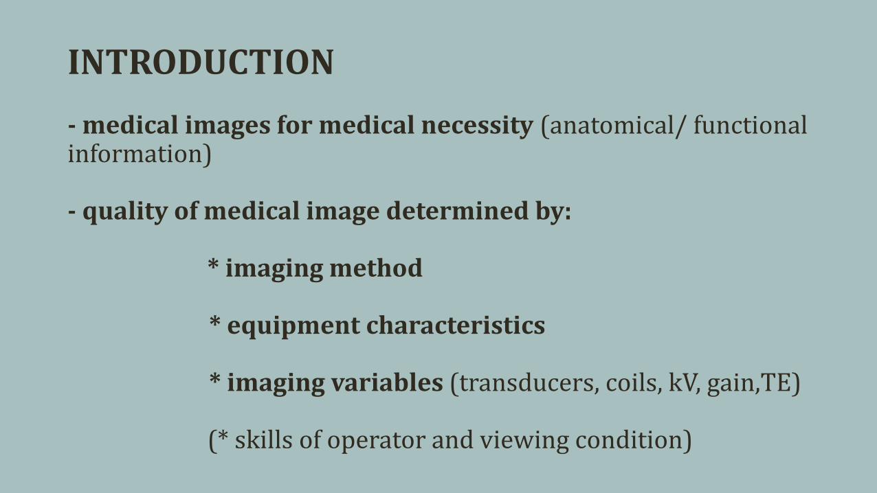
INTRODUCTION
- medical images for medical necessity (anatomical/ functional information)
- quality of medical image determined by:
* imaging method
* equipment characteristics
* imaging variables (transducers, coils, kV, gain,TE)
(* skills of operator and viewing condition)

Iterative reconstruction
* different imaging methods
* different equipment characteristics

* different equipment characteristics

* different imaging variables
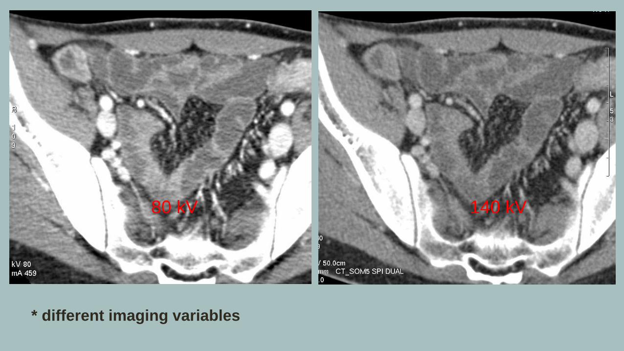
* different imaging variables
80 kV 140 kV


Contrast
- difference in tissue caracteristics between specific points
low contrast medium high contrast
- result of a number of different steps during creation, image processing and image displaying
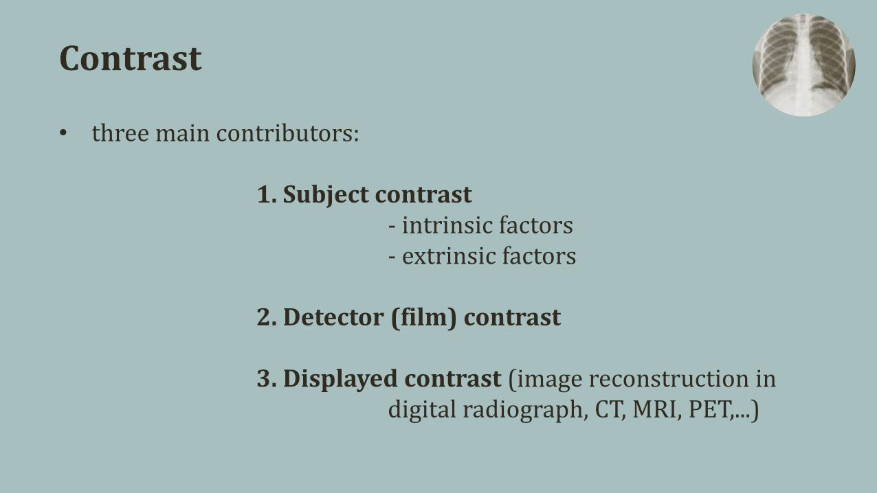
Contrast
• three main contributors:
1. Subject contrast- intrinsic factors- extrinsic factors
2. Detector (film) contrast
3. Displayed contrast (image reconstruction in digital radiograph, CT, MRI, PET,...)
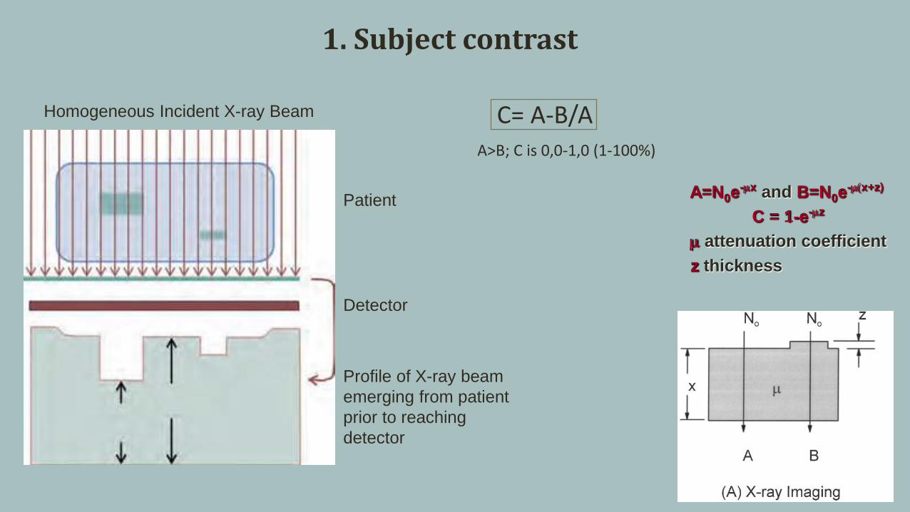
Homogeneous Incident X-ray Beam
Patient
Detector
Profile of X-ray beam
emerging from patient
prior to reaching
detector
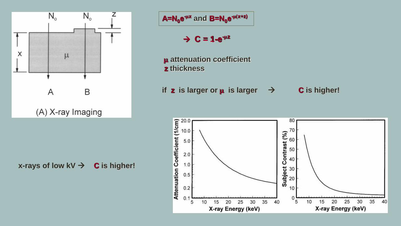
C= A-B/AA>B; C is 0,0-1,0 (1-100%)
A=N0e-mx and B=N0e
-m(x+z)
C = 1-e-mz
m attenuation coefficient
z thickness
1. Subject contrast
A=N0e-mx and B=N0e
-m(x+z)
C = 1-e-mz
m attenuation coefficient
z thickness
if z is larger or m is larger C is higher!
x-rays of low kV C is higher!
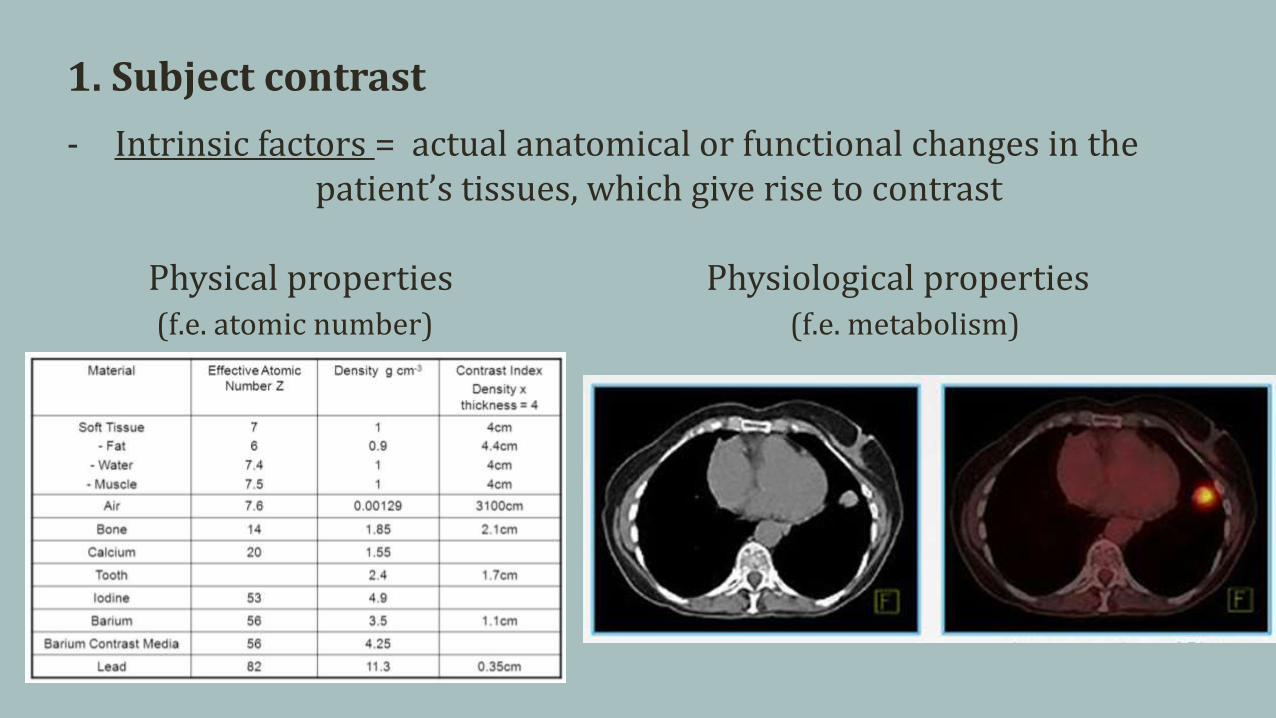
1. Subject contrast
- Intrinsic factors = actual anatomical or functional changes in the patient’s tissues, which give rise to contrast
Physical properties Physiological properties(f.e. atomic number) (f.e. metabolism)
•

1. Subject contrast
- Extrinsic factors = optimization of image-acquisition protocol to enhance subject contrast
Changing x-ray energy Contrast agent

1. Subject contrast
Changing TR i TE

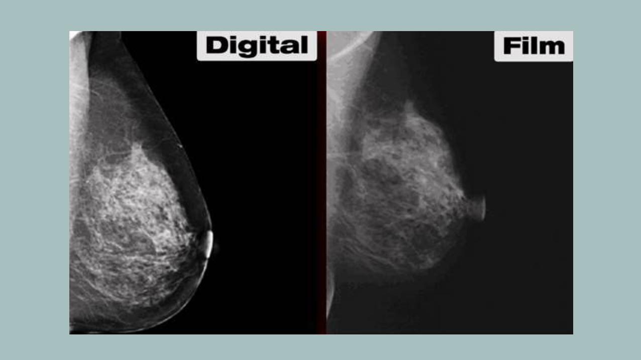
2. Detector (film) contrast

2. Detector (film) contrast

3. Displayed contrast
- raw image information is processed into an image that is finallymeant for physician viewing
- medical images have bit depths ranging from 10, 12,14 bits(1024, 4096 to 16384 shades of gray)
- Modern displays capable of displaying 8-bit to 10-bit (256 to 1024shades of gray)
display computer needs to convert the higher bit depth data encoded on the image to the spectrum of gray scale on the monitor

lung window (W 1600/ C -600 H.U)

mediastinal window (W 350/ C 40 H.U.)

bone window (W 1600/ C 300 H.U.)

Resolution
- Spatial resolution in radiology refers to the ability of the imaging modality to differentiate two objects

Point Spread Function, PSF
= response of an imaging system to a point source
• most basic measure of resolution properties of an imaging system
• describes the extent of blurring that is introduced by an imaging system
• two-dimensional (2D) function PSF(x,y)
• Rotationally symmetric/ asymmetric
• describes the extent of blurring that is introduced by an imaging system
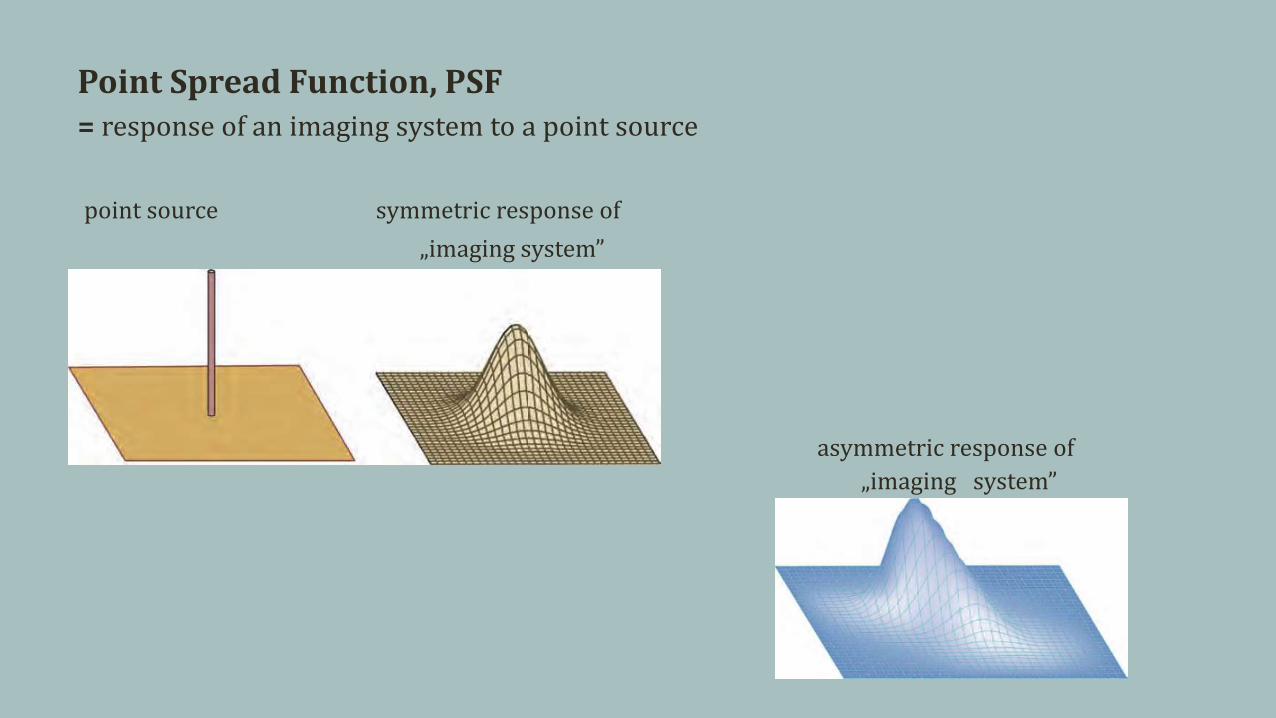
Point Spread Function, PSF= response of an imaging system to a point source
point source symmetric response of
„imaging system”
asymmetric response of
„imaging system”

Stationary Imaging System
- the PSF remains constant over the FOV of the imaging system
Nonstationary Imaging System
- has a different PSF depending on the location in the FOV
- assymetric system

Line Spread Function, LSF Edge Spread Function, ESF

Slit imaging in projection radiography Imaging a plane in tomographiy sytem
Image of Line
Profile of line is measuredperpendicular to the line

gaussian blur original increasing edge enhancement
Results of 2D image processing using a variety of different convolution kernels

G(x )=
H(x ') k (x-x ') dx ‘= H(x ) k(x )
LSF (x )=PSF (x, y) ⊗ LINE( y)
LSF x =
PSF x y dy

Modulation Transfere Function, MTF= spatial frequency response of an imaging system
• measures resolution in frequency domain(Fourier Transformation)
• measured in line pairs per millimeter (lp/mm)• limited by Nyquist limit
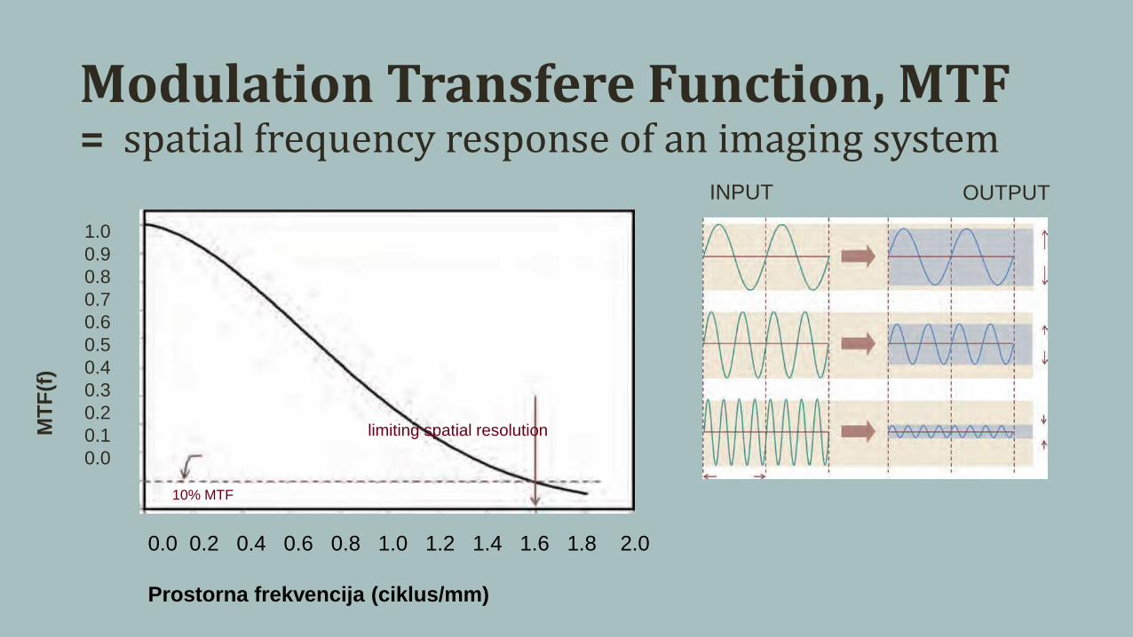
Modulation Transfere Function, MTF= spatial frequency response of an imaging system
0.0 0.2 0.4 0.6 0.8 1.0 1.2 1.4 1.6 1.8 2.0
Prostorna frekvencija (ciklus/mm)
10% MTF
limiting spatial resolution
1.0
0.9
0.8
0.7
0.6
0.5
0.4
0.3
0.2
0.1
0.0
MT
F(f
)
OUTPUTINPUT


Noise
= irregular granular pattern
- degrades image information (render images non-diagnostic)
- present in all electronic systems
- originates from a number of sources
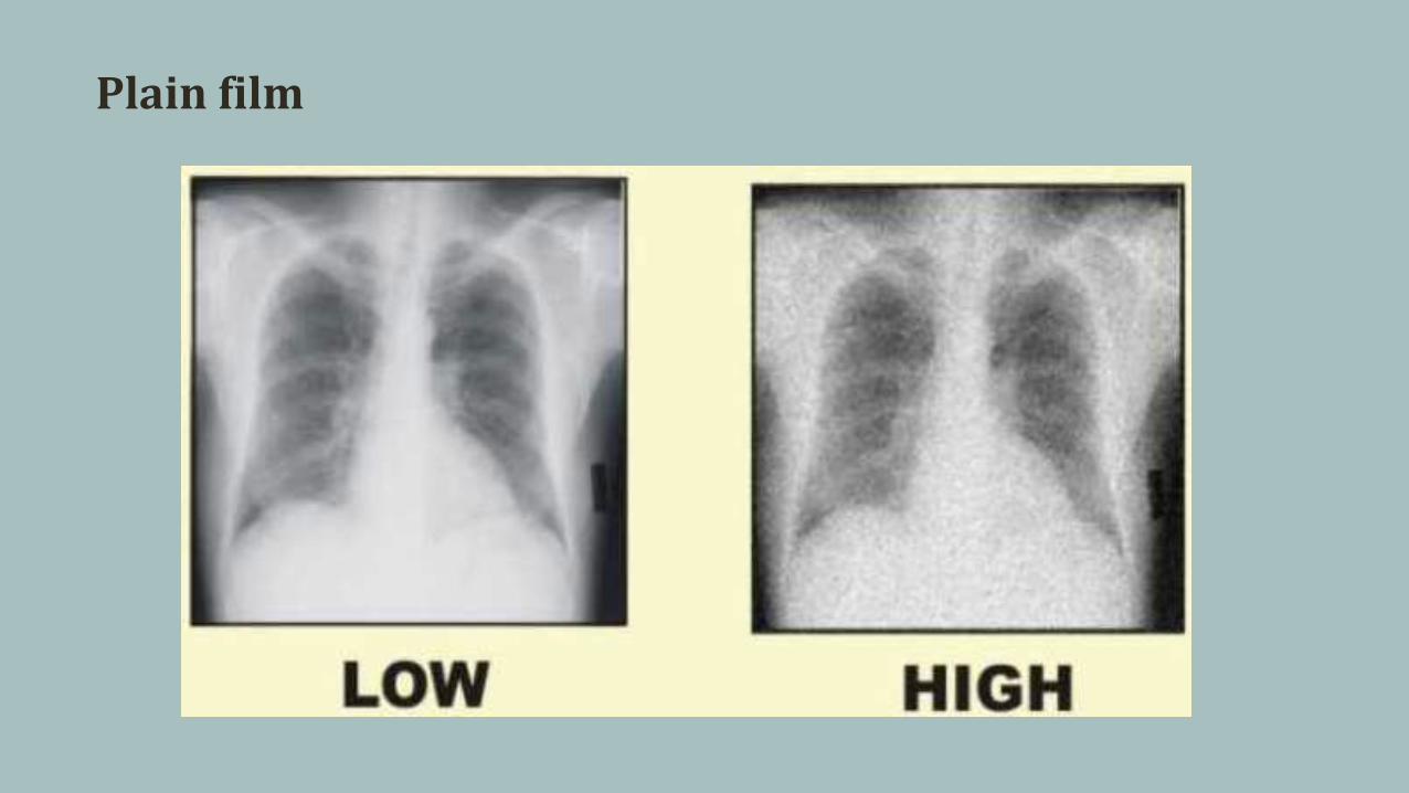
Plain film

Plain film
Decreasing radiation intensity

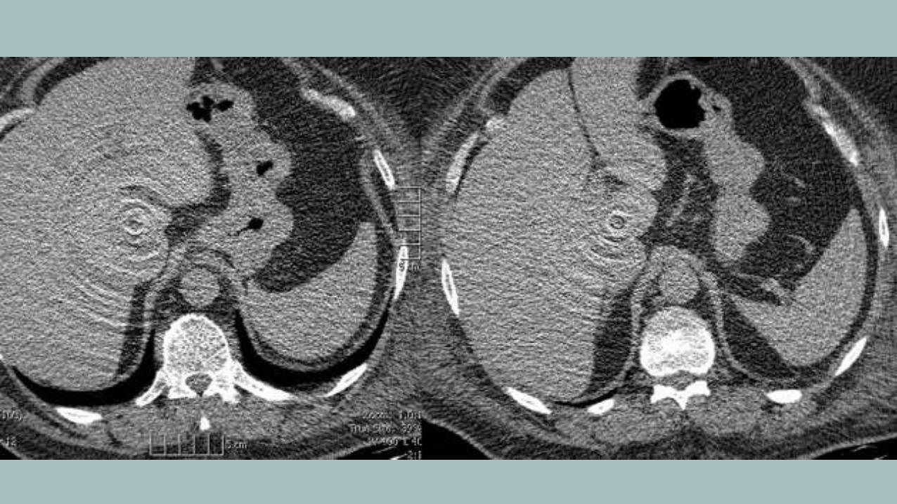
CT
- Noise can be decreased by increasing mAs
- Noise can be decreased by changing filters during reconstruction
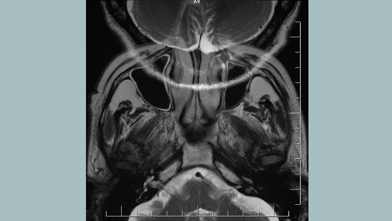
MRI
- main source is the patient's body (RF emission due to thermal motion)
- Noise can be decreased:
- use the correct coil and ensure that it is well tuned
- use a large FOV
- select thick slices

Artifacts


Medical images for medical necessity?
Department of Brain and Cognitive Sciences, MIT / Athinoula A.
Martinos Imaging Center at the McGovern Institute for Brain Research
Neuroscientist Rebecca Saxe captured an incredible image of herself holding her 2-month-old son, Percy, and it
may be the first image of its kind. She and her colleagues took the image simply because they wanted to see it, not
for any specific diagnosis or study.