imagine the result - new york state department of ... · imagine the result cwm chemical services,...
TRANSCRIPT

Imagine the result
CWM Chemical Services, LLC
Engineering Report
Residuals Management Unit 2
Model City Facility 1550 Balmer Road Model City, Niagara County, New York
April 2003 Revised August 2009 Revised February 2013 Revised June 2013 Revised November 2013
NYSDEC OHMS Document No. 201469232-00007
Table of Contents
Accompanying Set of Plans vi
Facility Information viii
1. Introduction 1
1.1 Facility Overview 1
1.2 Description of RMU-2 Design 1
1.3 Zoning and Utilities 2
1.4 Required Permits and Approvals 3
2. General Site Information 5
2.1 Location and Description 5
2.2 Past Geologic and Hydrogeologic Studies 5
2.2.1 Site Geology 6
2.2.2 Site Hydrogeology 8
2.2.2.1 Hydraulic Conductivity of Site Soils 9
3. Design 10
3.1 Design Overview 10
3.2 Regulatory Requirements for RMU-2 10
3.3 RMU-2 Design Components 17
3.3.1 MSE Wall 17
3.3.2 Intercell Berms 17
3.3.3 Liner System 18
3.3.3.1 Liner System Subgrades 19
3.3.3.2 Primary Leachate Collection System 21
3.3.3.3 Secondary Leachate Collection System 23
3.3.3.4 Leachate Pumping System 24
3.3.4 Final Cover System 26
3.3.5 Surface-Water Management Features 27
163911351 engineering report revised november 2013 i
NYSDEC OHMS Document No. 201469232-00007
Table of Contents
3.3.5.1 Capped Conditions 27
3.3.5.2 Uncapped Conditions 29
3.4 Slope Stability Calculations 29
3.4.1 RMU-2 Slope Stability 30
3.4.1.1 Final Buildout Stability 30
3.4.1.2 Final Cover System Veneer Stability 31
3.4.1.3 MSE Wall Stability 32
3.4.1.4 Fill Progression Stability 32
3.4.1.5 Excavation 33
3.4.2 Fac Pond 5 Berm Slope Stability 33
3.5 Fac Pond 5 Design 33
4. Construction 36
4.1 Overview 36
4.2 Site Preparation 36
4.2.1 Elimination of Fac Ponds 3 and 8 37
4.2.2 Construction of Fac Pond 5 37
4.2.3 Abandonment of Monitoring Wells and Piezometers 38
4.2.4 New Infrastructure Construction 39
4.2.5 Site Drainage and Vehicle Access 40
4.3 Excavation 40
4.4 MSE Wall and Intercell Berms 41
4.4.1 MSE Wall Perimeter Berm 41
4.4.2 Intercell Berms 42
4.5 Low-Permeability Cut-Off Wall 42
4.6 Construction Observation and Inspection 43
4.6.1 Compacted Clay Layer 43
4.6.2 Geosynthetic Liners 43
163911351 engineering report revised november 2013 ii
NYSDEC OHMS Document No. 201469232-00007
Table of Contents
4.6.3 Leachate Collection and Conveyance Systems 44
4.6.4 Operations Layer 45
4.7 Final Cover System 46
4.8 Gas Venting 46
4.9 Stormwater Retention Area Upgrades 46
5. Operation 48
5.1 Waste Receipt and Handling 48
5.2 Waste Volume and Site Life 48
5.3 Equipment 48
5.4 Daily Cover Material 48
5.5 Miscellaneous Operational Considerations 49
5.6 Safety and Fire Control 49
5.7 Leachate Collection and Pumping System 49
5.8 Air, Ground and Surface-Water Monitoring 50
5.9 Surface-Water Management 50
Appendices
A Geotechnical Investigations
A-1 Report Entitled Selection of Soil Properties for Geotechnical Evaluation of RMU-2 Design (P.J. Carey & Associates, PC, August 2009, Revised February 2013)
A-2 Letter Report Entitled Geotechnical Investigation for Proposed Residuals Management Unit Number 2 Western Expansion Area (Golder, December 2002)
A-3 Laboratory Testing – Structural Fill (Geotechnics, August 2009)
A-4 Report Entitled Landfill Footprint Analytical Data Study and Western Boundary Relocation Investigation, Residuals Management Unit Number 2 (Golder, August 2009)
A-5 Letter Report on RMU-2 Glaciolacustrine Clay Sampling & Lab Testing Results (Golder, February 2013)
B B-1 Figure Entitled “Glaciolacustrine Silt/Sand Unit Potentiometric Contour Map – May 15, 2001” (Golder, January 2002)
163911351 engineering report revised november 2013 iii
NYSDEC OHMS Document No. 201469232-00007

Table of Contents
B-2 Figure Entitled “Glaciolacustrine Silt/Sand Unit Potentiometric Surface Contours – October 2004” (Golder, January 2005)
C Geotechnical Calculations
C-1 RMU-2 Settlement Analysis
C-2 Waste Settlement Analysis
C-3 Excavation Heave Analysis
C-4 Hydrostatic Uplift
C-5 RMU-2 Stability Analysis – Final Buildout
C-6 RMU-2 Final Cover Stability
C-7 Liquefaction Analysis
C-8 RMU-2 MSE Wall Analysis
C-9 RMU-2 Initial Fill Progression
C-10 Fac Pond 5 Stability
D Geosynthetic Calculations
D-1 Geotextile Design
D-2 Sideslope Liner System Veneer Stability Analysis
E Leachate Collection and Conveyance Calculations
E-1 Liner System Geocomposite Design
E-2 Leachate Collection Pipe Design
E-3 Sideslope Riser Pipe Design
E-4 Leachate Management – Cell 20
E-5 Leachate Management – Conceptual Landfill Progression Phase 1
F Leachate Transfer System Calculations
F-1 Leachate Transfer Calculations
F-2 RMU-1/RMU-2 Leachate Forcemain and Tank T-150 Transfer Line Pipe Crush Analysis
G Final Cover Hydraulic Calculations
G-1 Final Cover Geocomposite Design
163911351 engineering report revised november 2013 iv
NYSDEC OHMS Document No. 201469232-00007

Table of Contents
G-2 Final Cover Collection Pipe Design
H Surface Water Drainage and Erosion Calculations
H-1 Surface Water Diversion Berm Design
H-2 Downchute Pipe Design
H-3 SLF 10 Diversion Channel Design
H-4 Perimeter Ditch Design
H-5 Perimeter Ditch Culvert Design
H-6 RMU-1/RMU-2 Culvert Design
H-7 Final Cover Soil Erosion Estimate
H-8 Stormwater Retention Basin Capacity Analysis
H-9 Fac Pond 5 Channel and Culvert Design
H-10 SLF 10 Ditch Design
H-11 RMU-2 South Ditch Design
H-12 Downchute Pipe Thrust Block Design
I Estimated Site Life
J Fac Pond Transfer Line Calculations
J-1 Fac Pond Transfer Line Pipe Crush Analysis at Road Crossings
J-2 Fac Pond Transfer Line Hydraulic Analysis
K Trailer Parking Area/Ramps Structural Calculations
L Facultative Pond Capacity Evaluation
163911351 engineering report revised november 2013 v
NYSDEC OHMS Document No. 201469232-00007
Residuals Management Unit 2 Engineering Report April 2003 Revised August 2009 Revised February 2013 Revised June 2013 Revised November 2013
Accompanying Set of Plans
Dwg. No. Title
1 Title and Index
2 RMU-2 Site
3 Excavation Grades
4 Subgrade Grades
5 Top of Operations Layer Grades
6 Top of Waste Grades
7 Top of Vegetative Cover Grades
8 Cell 20 Initial Fill Progression
9 Conceptual Waste Filling and Final Cover Sequencing
10 Cross Section 11,900 E
11 Cross Section 9,030 N
12 Typical Sump Plans
13 Typical Sump Profiles
14 Typical Sump Sections and Details
15 Liner System Sections and Details
16 MSE Wall Sections
17 MSE Wall Sections
18 MSE Wall Details
163911351 engineering report revised november 2013 vi
NYSDEC OHMS Document No. 201469232-00007

Residuals Management Unit 2 Engineering Report April 2003 Revised August 2009 Revised February 2013 Revised June 2013 Revised November 2013
19 Typical Intercell Berm
20 Final Cover Details
21 Final Cover Details
22 Surface Water Management Details
23 Surface Water Management Details
24 Surface Water Management Details
25 RMU-1/RMU-2 Culvert System Plan and Profile
26 Leachate Transfer System Plan
27 Leachate Collection and Transfer System Details
28 Riser Vault Plan and Sections
29 Remote Terminal Unit Panel and Primary and Secondary Control Panel Layouts
30 North Remote Control Building Layout
31 RMU-2 Riser Vault Electrical Diagram and Details
32 RMU-2 Riser Vault Instrumentation Diagram
33 SLF 12 Lift Station Modification
34 Tank T-150 Transfer Pipelines
35 Site Electrical Feed Relocation Plan
36 Site Water Supply Relocation Plan
163911351 engineering report revised november 2013 vii
NYSDEC OHMS Document No. 201469232-00007
Residuals Management Unit 2 Engineering Report April 2003 Revised August 2009 Revised February 2013 Revised June 2013 Revised November 2013
Facility Information
Name of Facility: CWM Chemical Services, LLC Residuals Management Unit 2 (RMU-2)
Address of Facility: 1550 Balmer Road Model City, New York 14107
Site Location: 1.9 miles east of New York State Route 18 along Balmer Road. Property aerial extent: 710 acres.
Operator: CWM Chemical Services, LLC
RMU-2 Capacity: Approximately 4,030,700 cubic yards total gross volume (i.e., from top of operations layer to top of final waste surface).
RMU-2 Acreage: Outside limit (to outside toe of mechanically stabilized earth wall): Approximately 43.5 acres.
Limit of waste: Approximately 36.9 acres.
Current Zoning: Heavy industrial (M-3)
Current Land Use: Waste treatment, storage, disposal and recovery facility.
Contact Person: Mr. Michael Mahar District Manager 1550 Balmer Road Model City, New York 14107
Report and Design: ARCADIS 6723 Towpath Road P.O. Box 66 Syracuse, New York 13214-0066 315.446.9120
163911351 engineering report revised november 2013 viii
NYSDEC OHMS Document No. 201469232-00007

Residuals Management Unit 2 Engineering Report April 2003 Revised August 2009 Revised February 2013 Revised June 2013 Revised November 2013
1. Introduction
1.1 Facility Overview
CWM Chemical Services, LLC (CWM), a wholly owned subsidiary of Waste Management, Inc., owns and operates the Model City Facility located in the Towns of Lewiston and Porter, New York. The Model City Facility is a state-of-the-art hazardous waste treatment, storage, disposal and recovery facility that accepts hazardous and industrial non-hazardous waste. All waste management facilities are located in the Town of Porter. Certain wastes may be accepted for pretreatment to meet land ban disposal criteria prior to landfilling. Other wastes may be landfilled directly without pretreatment.
The site contains several closed and one operational landfill, referred to as Residuals Management Unit 1 (RMU-1). This Engineering Report describes the design, construction and operation of a new on-site landfill (referred to as Residuals Management Unit 2 [RMU-2]), which will allow for the continuation of waste receipt and landfilling at the Model City Facility following closure of RMU-1.
RMU-2 is designed to provide an effective means of secure land disposal while safeguarding the environment with a double-composite liner system, leachate management and final cover system in accordance with New York State (NYS) hazardous waste landfill regulations. Wastes that meet land disposal restrictions (or other waste under variance) could be disposed in RMU-2. This Engineering Report addresses specific engineering criteria, provides background information on the RMU-2 design and is organized into individual sections discussing, among other items, general site information, regulatory requirements and engineering design, as well as the general construction requirements and typical landfill operation practices.
1.2 Description of RMU-2 Design
The design of RMU-2 is similar to current on-site landfills having double-composite liner systems – most notably, RMU-1. Rather than perimeter soil berms, RMU-2 will be bounded by a mechanically stabilized earth (MSE) wall to control stormwater runon and runoff. RMU-2 will be divided into six cells with intercell berms constructed of compacted clay. The cells will be constructed in phases as waste disposal capacity is needed. The floor of each cell will be sloped at a minimum of 1.0% (post-settlement) toward the cell centerline and ultimately to a leachate collection sump. RMU-2 top of final cover grades will extend from the perimeter anchor trench in the MSE wall at a 3H:1V slope to a grade break occurring at an elevation ranging from 418.0 feet above mean sea level (amsl) to 433.5 feet amsl and then at a variable slope (5 to 13%) to 440.0 feet amsl.
163911351 engineering report revised november 2013 1
NYSDEC OHMS Document No. 201469232-00007

Residuals Management Unit 2 Engineering Report April 2003 Revised August 2009 Revised February 2013 Revised June 2013 Revised November 2013
The design gross airspace between the top of the liner system and the bottom of the final cover system is approximately 4,030,700 cubic yards (cy), of which, approximately 3,934,000 cy is estimated to be available for waste placement. The balance of the design gross airspace will be occupied by select fill (for haul roads and around vertical risers). The minimum estimated site life of RMU-2 is approximately 11.1 years, based on annual gate receipts of 500,000 tons per year and an in-place waste density of 1.5 tons per cy. A longer site life would result if annual gate receipts are less and/or the waste density is higher.
The proposed RMU-2 footprint is depicted on Permit Drawing No. 2. Construction of RMU-2 will require the demolition and, in some cases, relocation of various structures related to the Model City Facility’s infrastructure as part of this project, including the Full and Empty Trailer Parking Areas, Stabilization Facility trailer parking areas, Drum Management Building, Emergency Response Garage, Heavy Equipment Maintenance Building, the RMU-1 lift station and the trailer containment ramps for the secure landfill (SLF) 10 leachate holding building and SLF 1-11 Oil/Water Separator Building. A number of existing groundwater monitoring wells are located within or are in close proximity to the limits of RMU-2. These wells will be decommissioned and, if the wells are part of current monitoring events, replacement wells will be installed. A listing of affected wells is presented in Section 4 of this Engineering Report.
Existing Facultative (Fac) Ponds 3 and 8 are within the footprint of RMU-2 and will be eliminated in accordance with approved closure plan requirements. The existing Fac Ponds 1 and 2 will be retained for ongoing use following construction of RMU-2. A new Fac Pond 5 will be constructed and, in concert with the existing Fac Ponds 1 and 2, will provide temporary storage of treated leachate for qualification prior to off-site discharge.
Soils removed from the RMU-2 footprint during development will be used in the construction of the RMU-2 MSE wall and the compacted clay liner (soil properties permitting). Surplus soil and/or soil not meeting pertinent performance requirements for use in the MSE wall or compacted clay liner will be stockpiled on site for future use in other applications.
1.3 Zoning and Utilities
The portion of the Model City Facility on which RMU-2 will be constructed is currently zoned for heavy industrial use (i.e., M-3 in accordance with the Town of Porter Zoning Law), which allows waste management activities, including landfill operations. Existing active and inactive utilities within the footprint of RMU-2, including water, leachate, electrical and communication lines, will be either re-routed or removed, as necessary, prior to construction of RMU-2.
163911351 engineering report revised november 2013 2
NYSDEC OHMS Document No. 201469232-00007
Residuals Management Unit 2 Engineering Report April 2003 Revised August 2009 Revised February 2013 Revised June 2013 Revised November 2013
1.4 Required Permits and Approvals
Various permits and approvals will be required from federal, state and local authorities to construct and operate RMU-2. At the federal level, RMU-2 is governed by regulations established pursuant to the Toxic Substances Control Act (TSCA) and the Resource Conservation and Recovery Act (RCRA), as amended by the Hazardous and Solid Waste Amendments. In accordance with Title 40 of the Code of Federal Regulations Part 761, CWM will submit a TSCA Land Disposal Authorization Application for RMU-2 to seek approval from the United States Environmental Protection Agency (USEPA) for the disposal of TSCA regulated polychlorinated biphenyls.
At the state level, the USEPA has delegated the implementation of RCRA regulations to the New York State Department of Environmental Conservation (NYSDEC) under Title 6 of the New York Codes, Rules and Regulations (6 NYCRR) Part 373. The existing State Pollutant Discharge Elimination System permit for the Model City Facility will be revised to allow the discharge of treated wastewater from newly constructed Fac Pond 5 (instead of the current discharge from Fac Pond 3 or 8). Additionally, the following permit applications and documents will be submitted to the NYSDEC by CWM for compliance with state permitting requirements established in 6 NYCRR:
• Part 361 – Siting Certificate Application;
• Part 201 – Air Permit Application;
• Part 373 – Hazardous Waste Facility Permit Application;
• Section 401 (CWA) – Water Quality Certification;
• Part 617 – Draft Environmental Impact Statement, and
• Part 663 (Article 24) – Freshwater Wetlands Permit
Site wetland delineations performed by Environmental Design & Research, PC in 2002, 2009 and 2012 and jurisdictional determinations from the NYSDEC and the United States Army Corps of Engineers (USACE) indicate that the proposed area of RMU-2 and relocated facilities does not impact any NYSDEC-regulated wetlands, with the exception of impacts to a 100-adjacent area to a state-regulated wetland in the new Drum Building Area and contains approximately 2.5 acres of federal wetlands. A joint application under Sections 401 and 404 of the Clean Water Act and state Article 24 will be submitted.
163911351 engineering report revised november 2013 3
NYSDEC OHMS Document No. 201469232-00007

Residuals Management Unit 2 Engineering Report April 2003 Revised August 2009 Revised February 2013 Revised June 2013 Revised November 2013
At the local level, site plan approval and a permit for excavation will be obtained by CWM from the Town of Porter. Additional permits may be required as part of the relocation of existing facilities that are currently located within the RMU-2 footprint. These additional permits will be obtained as necessary.
163911351 engineering report revised november 2013 4
NYSDEC OHMS Document No. 201469232-00007
Residuals Management Unit 2 Engineering Report April 2003 Revised August 2009 Revised February 2013 Revised June 2013 Revised November 2013
2. General Site Information
2.1 Location and Description
RMU-2 will be located within the Model City Facility owned and operated by CWM. The facility encompasses approximately 710 acres, of which, about 630 acres are permitted for hazardous waste management operations. The area encompassed by the RMU-2 perimeter MSE wall is approximately 43.5 acres (to the outside toe of the MSE wall). RMU-2 will be accessible by existing site roads. As part of a former military complex, the Model City Facility has a local grid and elevation system to provide control for construction and survey documentation. This grid system is monumented at the site with numerous permanent monuments. For clarity, the RMU-2 survey location descriptions discussed in this Engineering Report, as well as those shown on the Permit drawings are referenced to this local grid system.
RMU-2 will be bordered to the north by the Stabilization Facility and to the south by SLF 10 and the Porter/Lewiston town line. The west side of RMU-2 will be bordered by the leachate tank farm (LTF), truck wash building and SLF 1-6. RMU-1 will border the east side of RMU-2. The limits of grading for RMU-2 meet local, state and federal property setback criteria. The proposed construction limits of RMU-2, including the MSE wall, extend from approximately 10,135E to 11,835E and from 8,135N to 10,000N. The approximate limits of waste (defined by the inside edges of the liner system anchor trench) extend from 10,185E to 11,790E and from 8,185N to 9,950N.
Presently, the portion of the Model City Facility that will comprise RMU-2 is relatively flat with little topographic relief. Surface-water runoff from within this area is currently managed using three stormwater basins: V01 to the north and V04 and V05 to the west. A significant portion of the RMU-2 area is currently occupied by Fac Ponds 3 and 8, which do not contribute to surface-water runoff. As part of the construction and subsequent closure of RMU-2, surface-water runoff from within the RMU-2 footprint will be redirected to stormwater basins V01, V04 and V05.
2.2 Past Geologic and Hydrogeologic Studies
Numerous past investigations have been conducted throughout the Model City Facility. Geologic and hydrogeologic investigations for the entire Model City Facility have been performed and were submitted to the NYSDEC and the USEPA in March 1985 (Hydrogeologic Characterization, Golder Associates, Inc. [Golder], March 1985). Two updates to the 1985 hydrogeologic report were also prepared and submitted in 1988 (Hydrogeologic Characterization Update, Golder, February 1988) and in 1993 (Hydrogeologic Characterization Update, Golder, June 1993). These studies detail the
163911351 engineering report revised november 2013 5
NYSDEC OHMS Document No. 201469232-00007

Residuals Management Unit 2 Engineering Report April 2003 Revised August 2009 Revised February 2013 Revised June 2013 Revised November 2013
physiography, drainage, regional geology, site stratigraphy, hydrogeology and site hydrologic parameters. In terms of hydrogeology, these studies focused on defining the uppermost aquifer underlying the Model City Facility, groundwater flow direction and rates.
Supplemental geologic investigations within the footprint of RMU-2 were also performed and presented in a letter report entitled Geotechnical Investigation for Proposed Residuals Management Unit Number 2 Western Expansion Area (Golder, December 2002), a report entitled Landfill Footprint Analytical Data Study and Western Boundary Relocation Investigation, Residuals Management Unit Number 2 (Golder, August 2009) and a letter report entitled RMU-2 Glaciolacustrine Clay Sampling and Lab Testing Results (Golder, February 2013). A copy of these reports is presented in Appendix A. In general, the 2002, 2009 2013 geotechnical investigations confirmed the geologic findings presented in the 1985, 1988 and 1993 site-wide investigations. The geologic and hydrogeologic information presented in the following sections were obtained primarily from the 1993 hydrogeologic report, with some additional detail from the 2002, 2009 and 2013 geotechnical reports.
2.2.1 Site Geology
The Model City Facility is located on the Ontario Plain, which is an area of low topographic relief between the Niagara Escarpment and Lake Ontario. The regional bedrock geology consists of the Queenston Formation that is represented by shales, siltstones and sandstones of Upper Ordovician to Silurian age. This formation is approximately 1,200 feet thick where it underlies the Niagara Escarpment. Thicknesses beneath the Model City Facility appear to be thinner, probably on the order of 1,000 feet, which is most likely due to erosion. The bedrock that directly underlies the Model City Facility is composed of reddish brown shale. The upper 5 to 15 feet of rock surface is generally highly weathered and broken. Typically, approximately 50 feet of unconsolidated deposits overlie the bedrock formation. This material was deposited during several Pleistocene glacial periods and consists of the following units (from bottom to top):
• Basal Red Till;
• Glaciolacustrine Silt/Sand;
• Glaciolacustrine Clay;
• Middle Silt Till (intermittently); and
163911351 engineering report revised november 2013 6
NYSDEC OHMS Document No. 201469232-00007

Residuals Management Unit 2 Engineering Report April 2003 Revised August 2009 Revised February 2013 Revised June 2013 Revised November 2013
• Upper Tills.
Each of these units is discussed in additional detail below.
Basal Red Till
Basal Red Till is the lowermost glacial unit at the site and is distinguished by its reddish color, high density and dry indurated texture. This deposit can be described as a very compact silt and coarse to fine sand with some gravel and shale fragments. The typical thickness of this unit is between 2 and 10 feet across the Model City Facility.
Glaciolacustrine Silt/Sand
Glaciolacustrine Silt/Sand deposits overlie the Basal Red Till and are represented mostly by reddish brown coarse to fine sand with some silt and gravel. The typical thickness of the Glaciolacustrine Silt/Sand varies between 0 and 25 feet beneath the RMU-2 footprint.
Glaciolacustrine Clay
The Glaciolacustrine Clay unit typically overlies the Glaciolacustrine Silt/Sand unit. The contrast between these two units is usually sharp. The Glaciolacustrine Clay is described as very soft to firm reddish brown to gray-brown silty clay with occasional silt and fine sand partings and seams. The thickness of Glaciolacustrine Clay generally varies from 5 to 25 feet across the Model City Facility. Within the RMU-2 footprint, the thickness of Glaciolacustrine Clay varies from less than 1 foot to 25 feet.
Middle Silt Till
Middle Silt Till is found intermittently across the Model City Facility between the upper and lower parts of the Glaciolacustrine Clay unit. The Middle Silt Till unit is described as reddish brown and gray coarse to fine sand and silt, trace of gravel, silt with occasional clay partings. The thickness of this unit varies from 3 to 12 feet across the facility.
Upper Tills
The Upper Tills unit is composed of three separate lithostratigraphic units, including the Upper Silt Till, the Upper Clay Till and the Upper Alluvium. The Upper Silt Till occurs intermittently throughout the Model City Facility. It directly overlies the Glaciolacustrine
163911351 engineering report revised november 2013 7
NYSDEC OHMS Document No. 201469232-00007

Residuals Management Unit 2 Engineering Report April 2003 Revised August 2009 Revised February 2013 Revised June 2013 Revised November 2013
Clay unit and is described as brown to gray-brown silt and coarse to fine sand with some gravel. The thickness varies from 3 to 10 feet across the Model City Facility.
The Upper Clay Till is continuous across the Model City Facility. It either overlies the Upper Silt Till or directly overlies the Glaciolacustrine Clay unit. The Upper Clay Till unit is typically described as brown to orange-brown mottled clayey silt to silty clay, faintly laminated, with some coarse to fine sand, trace of gravel and, occasionally, some organic material. The thickness of this unit varies from 2 to 18 feet.
The Upper Alluvium unit occurs intermittently across the Model City Facility and consists primarily of brown clayey silt with irregular laminations or compact gray silt. The thickness of this deposit varies from 2 to 6 feet.
2.2.2 Site Hydrogeology
The results of previous investigations (Golder 1985, 1988 and 1993) define the Glaciolacustrine Silt/Sand unit as the uppermost aquifer beneath the Model City Facility. Concentrations of total dissolved solids indicate that groundwater in this unit is considered saline under the NYSDEC water quality standards and is, therefore, not suitable for use as a potable water supply. The Glaciolacustrine Silt/Sand unit is a confined aquifer. The Glaciolacustrine Clay, Middle Silt Till and Upper Tills have much lower hydraulic conductivities than the Glaciolacustrine Silt/Sand and function as aquitards. The Glaciolacustrine Clay unit is the major aquitard restricting vertical groundwater flow to the Glaciolacustrine Silt/Sand aquifer from the surface. As reported in the 1985, 1988 and 1993 hydrogeologic reports, lateral flow in the Glaciolacustrine Silt/Sand aquifer is generally north-northwest.
Appendix B contains Glaciolacustrine Silt/Sand potentiometric contours from May 15, 2001 and October 2004 well data. In general, these datasets represent the periods of greatest potentiometric heads since regular recording of site-wide groundwater elevation data began in the early 1980s. (Although water-level data have been collected routinely for the Glaciolacustrine Silt/Sand unit since 1977, data collected through 1983 are generally not considered reliable enough for comparison purposes because several different procedures were used to measure groundwater elevations, each with varying degrees of accuracy.) Across the majority of the RMU-2 footprint, the May 2001 dataset indicates higher heads than the October 2004 dataset. Consequently, the May 2001 monitoring event data and resulting piezometric contours were used in the design of RMU-2.
In addition to the confined Glaciolacustrine Silt/Sand aquifer, there is a near-surface-water table in the Upper Tills. Groundwater in this unit is not considered usable as a
163911351 engineering report revised november 2013 8
NYSDEC OHMS Document No. 201469232-00007

Residuals Management Unit 2 Engineering Report April 2003 Revised August 2009 Revised February 2013 Revised June 2013 Revised November 2013
potable water supply due to water quality and quantity. Potentiometric contours in the Upper Tills indicate that lateral flow of shallow groundwater in this unit is predominantly north-northwest, following the slope of the ground surface. In addition to surface topography, potentiometric contours in this unit are also affected by area drainage features and ponded areas. Barring the effects of these features, the water-table surface in the Upper Tills unit is approximately parallel to the ground surface. Its depth is noted to be about 2 to 5 feet below grade.
2.2.2.1 Hydraulic Conductivity of Site Soils
Numerous field and laboratory hydraulic conductivity tests (1985, 1988 and 1993) have been performed on the geologic units beneath the Model City Facility. The following table presents the most recently updated (Golder, 1993) geometric mean hydraulic conductivities for each unit discussed in Section 2.2.1, as well as for the underlying bedrock units.
Unit Geometric Mean Hydraulic Conductivity [cm/s] (2)
Number of Tests Type of Tests
Upper Alluvium kh = 3 x 10⁻⁶ kv = 1 x 10⁻⁵
4 1
Field Laboratory
Upper Glacial Tills kh = 2 x 10⁻⁶ kv = 6 x10⁻⁷ (3)
182 6
Field Laboratory
Middle Silt Till kh = 3 x 10⁻⁶ kv = 1 x 10⁻⁷
5 2
Field Laboratory
Glaciolacustrine Clay kh = 5 x 10⁻⁸ kv = 2 x 10⁻⁸
54 29
Field/Laboratory Laboratory (4)
Glaciolacustrine Silt/Sand kh = 3 x 10⁻⁵ kv = 1.6x10⁻⁵ (6)
87 50
Field Field (5)
Basal Red Till kh = 4x10⁻⁸ kv = 3x10⁻⁸
2 4
Field Laboratory
Shallow Rock k = 1x10⁻⁵ 11 Field Deep Rock k = 5x10⁻⁶ 3 Field
Notes: (1) cm/s = centimeters per second (2) k = bulk hydraulic conductivity kh = hydraulic conductivity in the horizontal direction kv = hydraulic conductivity in the vertical direction (3) kv estimated to be 6 x 10⁻⁷ cm/s due to structural discontinuities in the Upper Tills (see
Sections 6.1.7 and 7.4 of 1993 Hydrogeologic Characterization Update [Golder, 1993]). (4) Undisturbed boring samples. (5) Field tests performed in Revised Groundwater Monitoring System wells. (6) kv is assumed equal to kh for the coarse portion of the Glaciolacustrine Silt/Sand unit.
163911351 engineering report revised november 2013 9
NYSDEC OHMS Document No. 201469232-00007

Residuals Management Unit 2 Engineering Report April 2003 Revised August 2009 Revised February 2013 Revised June 2013 Revised November 2013
3. Design
3.1 Design Overview
The design of RMU-2 is similar to previously constructed landfills at the Model City Facility having double-composite liner systems. This section provides an overview of the design of RMU-2, including regulatory requirements and other design considerations. Specific components of the RMU-2 design, including the MSE wall, intercell berms, liner system, final cover system and surface-water management features, are discussed. Finally, a technical discussion of the results for the various slope stability calculations is presented.
3.2 Regulatory Requirements for RMU-2
RMU-2 has been designed to meet or exceed the requirements for hazardous waste landfills as specified in 6 NYCRR Part 373-2.14. This section identifies specific regulatory requirements under 6 NYCRR Part 373 that govern the siting and design of RMU-2 and discusses the manner in which the RMU-2 design meets or exceeds them. For sake of clarity, each regulatory requirement is paraphrased in italics, followed by a discussion of the relevant RMU-2 features.
Required Site Characteristics [Set Forth in 6 NYCRR Part 373-2.14(b)]
• The soil beneath the landfill shall have a hydraulic conductivity of 1 x 10⁻⁵ cm/s or less.
As discussed in Section 2.2.2.1 of this Engineering Report, the various strata underlying RMU-2 have hydraulic conductivities ranging from 1 x 10⁻⁵ cm/s to 2 x 10⁻⁸ cm/s. The Glaciolacustrine Clay unit, which largely directly overlies the uppermost aquifer, has a vertical hydraulic conductivity of 2 x 10⁻⁸ cm/s.
• No waste shall be closer than 10 feet to an aquifer or bedrock.
As discussed in Section 2.2.1 of this Engineering Report, bedrock is typically 50 feet below ground surface across the Model City Facility. Because the deepest proposed bottom of waste grades is approximately 14.5 feet below the existing ground surface, the minimum required separation with respect to bedrock is achieved. By comparing the proposed bottom of waste grades against the top of the uppermost aquifer (i.e., the top of the Glaciolacustrine Silt/Sand unit), the minimum separation between the two is approximately 20 feet (based on the design top of operations layer grades and interpolated top
163911351 engineering report revised november 2013 10
NYSDEC OHMS Document No. 201469232-00007

Residuals Management Unit 2 Engineering Report April 2003 Revised August 2009 Revised February 2013 Revised June 2013 Revised November 2013
of Glaciolacustrine Silt/Sand elevations presented in Appendix C-4). Therefore, the minimum required waste separation with respect to the uppermost aquifer is also satisfied.
• No facility shall be located over groundwater recharge areas serving public water supplies.
As discussed in Section 2.2.2, the uppermost aquifer is not considered usable as a potable water supply due to water quality and quantity.
• Facilities shall be located at an elevation at least 5 feet above a flood plain unless provisions have been made to prevent the encroachment of flood waters.
RMU-2 is surrounded by an MSE wall that has a constant elevation along the outer edge of 350.0 feet amsl. Since the 100-year flood elevation for Twelve Mile Creek is approximately 320.2 feet amsl, the MSE wall will prevent the encroachment of flood waters into RMU-2.
• All fill areas or excavations shall terminate no closer than 50 feet from the property boundaries.
RMU-2 is located in the central portion of the site property. At its closest, the outside toe of the MSE wall is approximately 70 feet from the southern property line.
• The required horizontal separation distance between deposited hazardous waste and any surface water shall be determined for each facility after considering soil attenuation characteristics, drainage and natural or man-made barriers.
As discussed above, RMU-2 will be constructed with an MSE wall having a constant elevation of 350.0 feet amsl along the outer edge, which is above the 100-year flood stage for Twelve Mile Creek. The surface-water management features within RMU-2 have been designed to convey the peak flows from the 25-year, 24-hour storm event while providing the minimum freeboards recommended in the New York Guidelines for Urban Erosion & Sediment Control (August 2005). Additionally, the low-permeability cut-off wall constructed around the landfill will minimize the lateral movement of any liquids that may migrate through the landfill liner system.
163911351 engineering report revised november 2013 11
NYSDEC OHMS Document No. 201469232-00007

Residuals Management Unit 2 Engineering Report April 2003 Revised August 2009 Revised February 2013 Revised June 2013 Revised November 2013
Design and Operating Requirements [Set Forth in 6 NYCRR Part 373-2.14(c)(3)]
• The landfill shall have a liner system that is composed of two liners with leachate collection and removal systems above and between such liners. The liner system must have the following components:
- A top liner designed and constructed of materials (e.g., a geomembrane) to prevent the migration of wastes into the liner during the active life of the landfill and the post-closure care period.
The primary liner of RMU-2 exceeds this requirement by providing a composite top liner, which is not required under Part 373. The composite top liner consists of a high-density polyethylene (HDPE) geomembrane and a geosynthetic clay liner (GCL). Additionally, the HDPE geomembrane is 80-mil thick, which exceeds the recommended minimum 45-mil thickness (Minimum Technical Guidelines [USEPA, January 29, 1992]).
- A composite bottom liner consisting of at least two components. The upper component must be designed and constructed of materials (e.g., a geomembrane) to prevent the migration of waste into the bottom liner during the active life of the landfill and the post-closure care period. The lower component must be constructed of at least 3 feet of compacted soil material with a hydraulic conductivity of no more than 1x10⁻⁷ cm/s.
The bottom liner (i.e., the secondary liner) of RMU-2 consists of an 80-mil thick HDPE geomembrane and a minimum of 3 feet of compacted clay with a maximum hydraulic conductivity of 1 x 10⁻⁷ cm/s.
- The liner shall be constructed of materials having appropriate chemical properties and sufficient strength and thickness to withstand applied pressure gradients, physical contact with the waste and leachate, climatic conditions, the stress of installation and the stress of daily operations.
In addition to natural materials (e.g., a compacted clay layer, granular drainage layers and a layer of operations stone), the RMU-2 liner system includes standard landfill liner components (including HDPE geomembrane, geocomposite and GCL) that have been developed to withstand anticipated stresses associated with installation and operation. Similar materials have been used successfully in RMU-1 and other CWM and industry-wide land disposal units.
163911351 engineering report revised november 2013 12
NYSDEC OHMS Document No. 201469232-00007

Residuals Management Unit 2 Engineering Report April 2003 Revised August 2009 Revised February 2013 Revised June 2013 Revised November 2013
- The liner shall be placed on a foundation capable of supporting the anticipated loading to prevent failure of the liner due to settlement, compression or uplift.
The geotechnical calculations contained in Appendix C demonstrate the ability of the soils beneath RMU-2 to support the anticipated loading. The various components of the RMU-2 liner system have been designed to accommodate the estimated consolidation of the underlying soils. The excavation grades for RMU-2 have been established to preserve adequate soil pressure on the underlying Glaciolacustrine Silt/Sand unit to resist hydrostatic uplift from the confined aquifer. The hydrostatic uplift calculations contained in Appendix C-4 are based on groundwater levels measured during May 2001 and October 2004 that generally represent the maximum potentiometric heads in the Glaciolacustrine Silt/Sand unit since regular monitoring of site-wide groundwater levels began.
- The liner shall be installed to cover all surrounding earth likely to be in contact with waste or leachate.
The placement of waste in RMU-2 will be limited laterally to the inside edge of the liner system anchor trench at the top of the MSE wall. Surface-water runoff from active cells (i.e., leachate) will be managed within this limit of waste by providing temporary perimeter infiltration channels at the intersection of the waste surface and the liner system. These temporary channels will be filled as part of final cover system installation.
• The landfill liner system shall include a leachate collection system immediately above the top liner that will limit leachate depth over the liner to less than 1 foot or other design and operating conditions specified by the Commissioner. The leachate collection and removal system must be constructed of materials that are chemically resistant to the waste and leachate, of sufficient strength to prevent collapse under the applied loading from waste, final cover and construction equipment and be designed to function without clogging.
The leachate collection system above the liner (i.e., the primary leachate collection system) has been designed to collect and convey leachate to the cell sumps and to limit leachate depth to less than the thickness of the geonet within the geocomposite for leachate inflows occurring through waste mass. This is significantly less than the maximum 1 foot that is allowable under current Part 373 regulations. Additional modeling of the primary leachate collection system presented in Appendix E-4 for the first cell of RMU-2 was
163911351 engineering report revised november 2013 13
NYSDEC OHMS Document No. 201469232-00007

Residuals Management Unit 2 Engineering Report April 2003 Revised August 2009 Revised February 2013 Revised June 2013 Revised November 2013
performed to simulate conditions due to concentrated runoff draining into the infiltration channels at the cell perimeter. This modeling was performed under three operating conditions, including no waste, minimal waste, and waste placement in accordance with the initial fill progression. The modeling for the 25-year, 24-hour design storm event for the initial fill progression indicates that the expected peak leachate depths on the primary liner are below 1 foot. The modeling for the 25-year, 24-hour design storm event for the no waste and minimal impermeable waste scenarios indicate that the expected peak leachate depths on the primary liner are greater than 1 foot for periods of 2.9 and 3.2 days, respectively.
The primary leachate collection system consists of a layer of granular drainage material and a layer of geocomposite, both of which will have been subjected to laboratory testing for in-place hydraulic conductivity and transmissivity, respectively, prior to installation. The geocomposite transmissivity testing will be performed under loadings and with boundary conditions that are representative of field conditions and will demonstrate that the geocomposite meets or exceeds the minimum required transmissivity value presented in Appendix E-1. Potential clogging has been accounted for by inclusion of a factor of safety in the geocomposite transmissivity calculations. The primary leachate collection system also incorporates a perforated HDPE leachate collection pipe along the cell centerline. Calculations in Appendix E-2 demonstrate the capability of the leachate collection pipe to resist the anticipated applied loadings with resulting deflections less than the manufacturer-recommended maximum values. Potential clogging of the leachate collection pipe has been accounted for by inclusion of a factor of safety in the calculations. Additionally, cleanouts have been provided at both ends of each primary leachate collection pipe to allow annual inspection and flushing of the pipes, thereby reducing the potential for clogging.
• The landfill shall include a leachate collection and removal system immediately above the bottom composite liner that will also function as a leak detection system. This system must be capable of detecting, collecting and removing leaks at the earliest practicable time through all areas of the top liner likely to be exposed to waste or leachate. The leak detection system must be constructed with a minimum slope of 1.0 percent and be constructed of either 1 foot minimum granular drainage material having a hydraulic conductivity of 1 x 10⁻² cm/s or a geosynthetic material having a transmissivity of 3 x 10⁻⁵ m2/s. The leak detection system must be constructed of materials that are chemically resistant to the waste and leachate, of sufficient strength to prevent collapse under the applied loading from waste, final cover and construction
163911351 engineering report revised november 2013 14
NYSDEC OHMS Document No. 201469232-00007

Residuals Management Unit 2 Engineering Report April 2003 Revised August 2009 Revised February 2013 Revised June 2013 Revised November 2013
equipment and be designed to function without clogging. The leak detection system shall be constructed with sumps and liquid removal methods (e.g., pumps) to collect and remove liquids from the sumps and prevent leachate from backing up into the drainage layer. The design of each sump and removal system must provide a method for measuring and recording the volume of leachate present in the sump and of leachate removed.
The leachate collection system above the bottom composite liner (i.e., the secondary leachate collection system) has been designed to provide redundancy to the primary leachate collection system. In the event of a leak in the primary liner system, the secondary leachate collection system has the same hydraulic capacity as the primary leachate collection system. The secondary leachate collection system employs both a layer of geocomposite and a 1-foot-thick layer of granular drainage material. The secondary leachate collection system also incorporates a perforated leachate collection pipe along the cell centerline. As with the primary leachate collection system, the components in the secondary leachate collection system have been designed to withstand conditions anticipated for the landfill liner system. As with the primary leachate collection system, the potential for clogging of the geocomposite has been accounted for by including a factor of safety. The geocomposite will be laboratory tested using anticipated field conditions to demonstrate adequate transmissivity. The sumps for the secondary leachate collection system contain automated pumps that, in automatic mode, will discharge to the leachate forcemain through a flow meter within the riser vault structure to measure the volume pumped. The pumps can also be controlled manually for discharge into either the leachate forcemain or tanker trucks. If pumped manually to a tanker truck, the difference in truck liquid level (before and after pumping commences) will be measured and converted to gallons to determine the volume of leachate pumped. Leachate levels within the sumps will be continuously monitored.
• The owner or operator shall collect and remove pumpable liquids in the leak detection system to minimize head on the bottom liner.
As stated above, automated pumps within the secondary leachate collection system sumps will minimize the head on the secondary liner system.
• The owner or operator of a leak detection system that is not located completely above the seasonal high water table must demonstrate that the operation of the leak detection system will not be adversely affected by the presence of groundwater.
163911351 engineering report revised november 2013 15
NYSDEC OHMS Document No. 201469232-00007

Residuals Management Unit 2 Engineering Report April 2003 Revised August 2009 Revised February 2013 Revised June 2013 Revised November 2013
Although the secondary leachate collection system will be installed at elevations below the historical high groundwater levels (in terms of potentiometric head for the Glaciolacustrine Silt/Sand unit), the presence of the confining Glaciolacustrine Clay layer greatly decreases the upward flow rate toward the liner system from the aquifer. Hydraulic calculations contained in the RMU-2 Response Action Plan (RAP) (ARCADIS, February 2013) indicate that the worst-case flow rate of groundwater into a cell from the confined aquifer is approximately 1.88 gallons per acre per day. This estimate is considered to be conservative because it is based on the historical high groundwater levels, as measured in May 2001, and does not consider the reduction in hydraulic head on the bottom of the secondary liner system due to the presence of the confining Glaciolacustrine Clay layer.
• The owner or operator must design, construct, operate and maintain a runon control system capable of preventing flow onto the active portion of the landfill during the 25-year, 24-hour storm event.
As discussed previously, the design of RMU-2 includes an MSE wall that has a constant top elevation that exceeds the 100-year flood stage of the neighboring Twelve Mile Creek. The MSE wall is approximately 30 feet above the surrounding terrain (based on a typical surrounding ground elevation of 320 feet amsl). Consequently, the MSE wall is sufficient to prevent runon onto the landfill during the 25-year, 24-hour storm event, as well as any floodwater from Twelve Mile Creek during the 25-year, 24-hour storm.
• The owner or operator must design, construct, operate and maintain a runoff management control system to collect and control at least the water volume resulting from the 25-year, 24-hour storm.
Stormwater management features within active portions of RMU-2 (including infiltration channels, culverts and lined stormwater retention basins) have been designed to manage the peak stormwater runoff rates and cumulative volumes for the 25-year, 24-hour storm event as leachate. Stormwater management features within closed (i.e., capped) portions of RMU-2 (including surface-water diversion berms, perimeter ditches, pipe downchutes and culverts) have also been designed to accommodate peak stormwater runoff rates from the final cover for the 25-year, 24-hour storm.
163911351 engineering report revised november 2013 16
NYSDEC OHMS Document No. 201469232-00007

Residuals Management Unit 2 Engineering Report April 2003 Revised August 2009 Revised February 2013 Revised June 2013 Revised November 2013
3.3 RMU-2 Design Components
RMU-2 is designed with six cells and a total area of approximately 43.5 acres, including the perimeter MSE wall. It is designed to allow construction in phases as waste disposal capacity is needed. This section discusses each of the major components of RMU-2 in detail, including the MSE wall, intercell berms, liner system, final cover system and surface-water management features. Included for each component is a discussion of the technical considerations that govern the design.
3.3.1 MSE Wall
As discussed earlier, RMU-2 will be surrounded by an MSE wall consisting of soil reinforced with geosynthetics. The MSE wall will control stormwater runon from adjacent areas of the Model City Facility and runoff from RMU-2. The top elevation of the MSE wall is constant along the length of the wall but varies across the wall width. The highest point across the MSE wall width is along the outside edge and has a design elevation of 350.0 feet amsl.
The primary advantage to using an MSE wall is increased airspace efficiency compared with a traditional unreinforced soil berm. That is, comparable airspace can be provided with an MSE wall-based landfill design in a smaller total footprint than if a soil berm were used. Because of the reinforcing properties of the geosynthetics used in the MSE wall, the outside sideslope of the MSE wall can be significantly steeper than the outside sideslope of an unreinforced soil berm. For RMU-2, the outside sideslope of the MSE wall will be 1H:4V (approximately 76 degrees). The inside sideslope of the MSE wall retains the typical 3H:1V slope to provide adequate liner system stability and meet regulatory requirements. Permit Drawing Nos. 16, 17 and 18 depict typical cross-sections and details for the MSE wall.
3.3.2 Intercell Berms
Each cell within RMU-2 will be segregated from adjacent cells by an intercell berm for the purpose of controlling surface water and leachate. The intercell berms will be constructed of compacted clay having a maximum hydraulic conductivity of 1 x 10⁻⁷ cm/s and will have a minimum top width of 5.0 feet. Details pertaining to the construction of the intercell berms and temporary liner system termination at the berms between construction phases are shown on Permit Drawing No. 19.
163911351 engineering report revised november 2013 17
NYSDEC OHMS Document No. 201469232-00007

Residuals Management Unit 2 Engineering Report April 2003 Revised August 2009 Revised February 2013 Revised June 2013 Revised November 2013
3.3.3 Liner System
The RMU-2 liner system has been designed to meet or exceed the requirements for hazardous waste landfills as specified in 6 NYCRR Part 373-2.14, entitled Secure Landburial Facilities. The regulations in this section require that landfills on which construction commences after January 29, 1992, or lateral expansions of existing landfills on which construction commences after July 29, 1992, have two or more liners and a leachate collection system above and between adjacent liners. As shown on Permit Drawing No. 15, the RMU-2 liner system consists of the following components (in descending order):
• Primary Leachate Collection System
- 1 foot of operations layer stone on the cell floors and 2 feet of operations layer stone on the cell sideslopes;
- A layer of non-woven geotextile on the cell floors;
- 1 foot of granular drainage material on the cell floors with an 8-inch-diameter perforated leachate collection pipe along the cell centerline; and
- A layer of geocomposite on the cell floors and sideslopes.
• Primary Liner System
- An 80-mil textured HDPE geomembrane on the cell floors and sideslopes; and
- A GCL layer on the cell floors (which extends a minimum of 15 feet up the cell sideslopes) that provides a maximum equivalent hydraulic conductivity equal to or less than 1.5 feet of compacted clay with a hydraulic conductivity of 1 x 10⁻⁷ cm/s.
• Secondary Leachate Collection System
- A layer of non-woven geotextile on the cell floors;
- 1 foot of granular drainage material on the cell floors with an 8-inch-diameter perforated leachate collection pipe along the cell floor centerline; and
163911351 engineering report revised november 2013 18
NYSDEC OHMS Document No. 201469232-00007

Residuals Management Unit 2 Engineering Report April 2003 Revised August 2009 Revised February 2013 Revised June 2013 Revised November 2013
- A layer of geocomposite on the cell floors and sideslopes.
• Secondary Liner System
- An 80-mil textured HDPE geomembrane on the cell floors and sideslopes; and
- 3 feet of compacted glacial till or other suitable clay having a maximum hydraulic conductivity of 1 x 10⁻⁷ cm/s on the cell floors and sideslopes.
As described above, the RMU-2 liner system is similar to that used in RMU-1, with the exception of the substitution of GCL for compacted clay in the primary liner system. The design of the liner system subgrades, leachate collection systems and leachate pumping system is discussed in greater detail below. Appendix D contains geosynthetic design calculations pertaining to the liner system.
3.3.3.1 Liner System Subgrades
The subgrade grading plan (i.e., the bottom of the liner system) shown on Permit Drawing No. 4 has been designed based on the predicted hydrostatic uplift force on the bottom of the sumps and the cell floors resulting from the historical high groundwater elevations measured in May 2001. In order to provide a stable sump excavation, the downward soil pressure acting on the top of the confined aquifer must equal or exceed the predicted hydrostatic uplift pressure. The hydrostatic uplift calculations in Appendix C-4 present the lowest allowable sump subgrade elevation for each cell in order to provide a minimum factor of safety of 1.0 (i.e., the downward soil pressure exactly equals the hydrostatic uplift pressure) for each sump excavation. A factor of safety of 1.0 is acceptable because the hydrostatic uplift pressure is based on historical high groundwater elevations and because of the small floor area of the sump excavation (approximately 15.5 feet by 21.5 feet, as measured at the inside toe of slope) and the limited time that the sump excavation will be open (approximately 24 hours from the time that the sump is excavated to the time that the installation of 3 feet of compacted clay is completed).
The factor of safety against uplift in the sumps will be verified by means of test pits and/or piezometric measurements in adjacent wells. Prior to sump excavation in each cell, piezometric measurements will be performed in the wells nearest the cell under construction. (In order to be applicable, the wells must be screened in the Glaciolacustrine Silt/Sand unit.) To evaluate potential uplift during sump excavation, a factor of safety for uplift using the measured piezometric heads will be calculated. If the resulting factor of safety is less than 1.0, the excavation of the sump will be postponed
163911351 engineering report revised november 2013 19
NYSDEC OHMS Document No. 201469232-00007

Residuals Management Unit 2 Engineering Report April 2003 Revised August 2009 Revised February 2013 Revised June 2013 Revised November 2013
until a minimum factor of safety of 1.0 is achieved by reducing the piezometric head either naturally or by mechanical means (e.g., active pumping).
After determination of an acceptable factor of safety (i.e., greater than or equal to 1.0), test pit(s) will be excavated at the sump location to the proposed sump bottom. The planimetric dimensions of the test pits will not exceed 4 feet by 4 feet. During test pit excavation, the certifying engineer will note any potential hydrostatic uplift, such as cracking or heaving of subsoils or influx of groundwater through the floor of the test pit. If the certifying engineer’s observations suggest hydrostatic problems, low-permeability soil will immediately be replaced and compacted in the test pits. Additional test pits may be excavated only after the piezometric levels from wells adjacent to the sump location indicate a measurable decrease from what was recorded prior to test pit excavation. If the test pits show no influence from hydrostatic pressure, the sump excavation will continue to the prescribed dimensions shown on Permit Drawing No. 12. Three feet of compacted clay (i.e., the compacted clay component of the secondary liner) will be placed within 24 hours from when the sump excavation was completed.
In addition to the lowest allowable sump subgrade elevations, Appendix C-4 also presents lowest allowable elevations for the cell floor subgrade immediately adjacent to the sump (i.e., at the floor of the cell but not in the sump) based on a minimum factor of safety of 1.2. The required cell subgrade factor of safety is greater than the factor of safety required for the sump subgrade because of the greater installation time of the secondary liner components across the cell floors. Finally, as discussed above, the subgrades satisfy the regulatory requirements in 6 NYCRR Part 373-2.14(b)(2) that specify a minimum vertical separation of 10 feet between waste and an aquifer (in this case, the top of the confined aquifer).
The cell subgrades are designed to provide a minimum slope of 1.0 percent toward the sumps (as measured both parallel and perpendicular to the cell centerline) following compression of the underlying Glaciolacustrine Clay layer. As discussed in Appendix C-1, consolidation of the Glaciolacustrine Clay is computed at regular intervals across the floor area in each cell to verify that the minimum slope of 1 percent parallel and perpendicular to the cell centerline following clay consolidation is achieved. Because the magnitude of clay consolidation is related to both clay thickness and applied pressure due to waste thickness and liner and final cover systems, calculation of clay consolidation using an array of points across the floor area provides a more comprehensive prediction of post-consolidation floor slopes.
163911351 engineering report revised november 2013 20
NYSDEC OHMS Document No. 201469232-00007

Residuals Management Unit 2 Engineering Report April 2003 Revised August 2009 Revised February 2013 Revised June 2013 Revised November 2013
3.3.3.2 Primary Leachate Collection System
The primary leachate collection system has been designed to limit leachate head to less than the thickness of the geonet core of the geocomposite for leachate inflows occurring through the waste mass, which is less than the maximum allowable 1 foot of head on the liner pursuant to 6 NYCRR Part 373-2.14(c)(1)(ii). As indicated in the leachate collection and conveyance calculations in Appendix E, the design flow rate for the primary leachate collection system is based on the predicted peak leachate flow rates during the 25-year, 24-hour storm event and is consistent with the design philosophy of RMU-1. As discussed in Appendix E-1, the required geocomposite transmissivity for the primary leachate collection system is based on the peak daily infiltration value from the overlying waste mass as determined using the Hydrologic Evaluation of Landfill Performance (HELP) model and Giroud’s equation. The required geocomposite transmissivity value obtained from Giroud’s equation is based on a maximum leachate level on the cell floor that is equal to the thickness of the geonet core of the geocomposite. This demonstrates that the primary leachate collection system can convey the flow associated with the peak daily infiltration value through the waste mass and not exceed the regulatory maximum 1 foot of leachate head. Because the additional hydraulic capacity provided by the 1 foot of granular drainage layer is not included in the calculation, the required geocomposite transmissivity value is considered to be conservative (i.e., greater than that required if the effect of the granular drainage layer were included).
Appendix E-1 also presents a second required geocomposite transmissivity value for the closed (i.e., capped) condition. Although the infiltration rate to the primary leachate collection system will be much less for the closed condition than for the active condition due to the presence of additional waste material and the final cover system, the recommended factors of safety are significantly higher for the closed condition. This is due to the temporary nature of the active condition and the reduced likelihood of the occurrence of the 25-year, 24-hour storm event while the cell is active. As indicated in Appendix E-1, the required geocomposite transmissivity value for the active condition is greater than that for the closed condition; therefore, the active condition transmissivity value governs. It should be noted that slopes used in the calculation for the leachate collection system under the active condition are based on the pre-consolidation grades, as shown on the various grading drawings. This slope condition is considered appropriate for the active phase, because the thickness of waste placement during this time is not likely to be significantly greater than the pre-development native soil thickness. Conversely, for the closed condition, slopes used in the calculation for the leachate collection system have been reduced from those depicted on the grading drawings to account for the consolidation of the underlying Glaciolacustrine Clay layer.
163911351 engineering report revised november 2013 21
NYSDEC OHMS Document No. 201469232-00007

Residuals Management Unit 2 Engineering Report April 2003 Revised August 2009 Revised February 2013 Revised June 2013 Revised November 2013
A perforated HDPE leachate collection pipe will be installed along the cell centerline in the primary leachate collection system to convey leachate into the sump. The leachate collection pipe has been sized to provide hydraulic capacity in excess of the maximum possible flow rate from the upgradient geocomposite. Calculations in Appendix E-2 demonstrate the required flow capacity of the leachate collection pipe, as well as the ability of the leachate collection pipe to resist the anticipated applied loads while not exceeding the maximum allowable deflection (based on manufacturer’s recommendations) nor the maximum allowable wall compressive stress. Appendix E-2 also evaluates the minimum required cover to allow operation of truck traffic over the leachate collection pipe. This latter calculation demonstrates that adequate cover will be in place following completion of the operations layer and thus, no additional cover is needed above the operations layer to allow operation of truck traffic over the pipe.
Based on experience with RMU-1, twice the amount of pipe perforations have been included into the design of the primary leachate collection pipe compared to the design of the primary leachate collection pipe for RMU-1. The calculations in E-2 indicate a factor of safety of approximately 22.2, which allows for up to 95 percent clogging of the perforations before the inflow capacity of the leachate collection pipe is reduced to the point that it equals the maximum possible flowrate able to be conveyed through the geocomposite. Further, it is noted that the factor of safety is with respect to the maximum possible flowrate based on the design transmissivity of the geocomposite which, in itself, includes an additional factor of safety compared to the peak flows expected to be conveyed through the geocomposite.
The primary leachate collection system in each cell will slope toward a sump that is depressed approximately 3.5 feet into the floor of the cell. Leachate will be removed from the primary leachate collection system sump using a submersible pump that will be lowered into the sump via a 24-inch-diameter HDPE sideslope riser pipe (consistent with the design of the RMU-1 sumps). Leachate collected by the submersible pump will be transferred via flexible hose back up the sideslope riser pipe to the riser vault structure, which is located at the upgradient end of the sideslope riser pipe on the perimeter berm. As with RMU-1, the design of the RMU-2 sideslope riser pipes allows for collection of leachate from the sumps without penetration of the liner system. The sideslope riser pipe will be fitted with an elbow at the toe of the sideslope to allow the pipe to extend across the floor of the sump. The horizontal extension of the sideslope riser pipe will be perforated to allow leachate to enter the pipe and be collected with the submersible pump. The majority of the leachate will reach the sump via the leachate collection pipe and a tee fitting in the leachate collection pipe will allow the flow within the pipe to drain directly into the interior of the sideslope riser pipe, thus bypassing the perforations of the sideslope riser pipe entirely and reducing the clogging potential of the sideslope riser pipe. Under normal operating conditions, only leachate that is not
163911351 engineering report revised november 2013 22
NYSDEC OHMS Document No. 201469232-00007

Residuals Management Unit 2 Engineering Report April 2003 Revised August 2009 Revised February 2013 Revised June 2013 Revised November 2013
intercepted by the leachate collection pipe will enter the sideslope riser pipe via the perforations. Calculations in Appendix E-3 demonstrate the ability of the perforations in the horizontal portion of the sideslope riser pipe to convey the estimated peak flow rate from both the leachate collection pipe and the geocomposite that discharges into the sump. This analysis is conservative because it assumes all leachate generated in the cell must enter the sideslope riser pipe through the perforations. It does not account for the direct discharge of leachate through the leachate collection pipe and into the sideslope riser pipe that occurs under normal operating conditions. Appendix E-3 also demonstrates the ability of the sideslope riser pipe to resist the anticipated applied loads while not exceeding the maximum allowable deflection (based on the manufacturer’s recommendations). A second means of access into the primary leachate collection system sump is accomplished via a 24-inch-diameter HDPE vertical riser pipe that tees into the horizontal portion of the sideslope riser pipe (consistent with the design of the RMU-1 sumps). The vertical riser pipe will be protected by concrete manhole sections as waste filling progresses.
Appendices E-4 and E-5 simulate the performance of the entire primary leachate collection system (including the geocomposite, the granular drainage layer, the operations layer, the leachate collection pipe, and infiltration channels at the landfill perimeter) during the 25-year, 24-hour design storm. These appendices were prepared to simulate conditions within the primary leachate collection systems with storm-related inflows at the perimeter of the cells due to the infiltration channels, Appendix E-4 evaluates Cell 20 under three operating conditions, including no waste, minimal waste, and waste placement in accordance with the initial fill progression. Appendix E-5 evaluates Cells 18, 19, and 20 (Phase 1 of the conceptual landfill progression as shown on Permit Drawing No. 9 but with Cell 19 assumed to be newly constructed and with no waste in place) during the 25-year, 24-hour design storm. These appendices highlight the importance of constructing detention basins within the landfill to limit drainage areas to the infiltration channels. Specifically, the appendices indicate that once stormwater runoff to the infiltration channels is reduced by diversion to detention basins, peak leachate depths will be less than 1 foot and there will be no times of exceedance. Prior to that, peak leachate depths of approximately 2 feet and times of exceedance of approximately 3 days will occur on the cell floors. It is noted that these are peak conditions resulting from the 25-year, 24-hour design storm and are not representative of typical operating conditions.
3.3.3.3 Secondary Leachate Collection System
The secondary leachate collection system has been designed to provide redundancy in the event the primary liner system fails. To be conservative, the secondary leachate collection system is essentially identical in composition to the primary leachate
163911351 engineering report revised november 2013 23
NYSDEC OHMS Document No. 201469232-00007

Residuals Management Unit 2 Engineering Report April 2003 Revised August 2009 Revised February 2013 Revised June 2013 Revised November 2013
collection system (i.e., the two systems have equal hydraulic collection and conveyance capacity to the cell sump).
As with the primary leachate collection system, access to the secondary leachate collection system sump is accomplished via a 24-inch-diameter HDPE sideslope riser pipe that will be installed parallel to that for the primary leachate collection system. Vertical riser pipes are not fitted to the secondary leachate collection system sumps due to their location below the primary liner system. Leachate will be collected from the secondary leachate collection system sumps with automated pumps. In automatic mode, the pumps will discharge to the leachate forcemain within the riser vault structure. The pumps can also be controlled manually for discharge into either the leachate forcemain or tanker trucks. Under manual control, the operator will record the initial level in the tanker truck, allow the pump to function until the low-level switch shuts it off and record the final level in the tanker truck. The difference between the tanker truck levels will be converted into gallons and recorded in the RMU-2 operating records.
The RAP discusses the flow capacities of the various components for the secondary leachate collection system, as well as the anticipated flows into the secondary leachate collection system from potential sources. As discussed in the RAP, the secondary leachate collection system flow capacities and anticipated inflows are used to establish the action leakage rates and response rates for the cells comprising RMU-2. Response actions required for each of these trigger levels are also discussed in the RAP.
3.3.3.4 Leachate Pumping System
The RMU-2 leachate pumping system will consist of a series of riser vault structures (one for each cell) along the perimeter MSE wall of RMU-2 and two identical underground leachate forcemains (one for conveying combined primary and secondary leachate collection system flows and a redundant line to be used as necessary). As discussed in Section 1.2, construction of RMU-2 will require the demolition of the RMU-1 lift station. Consequently, leachate collected from both RMU-1 and RMU-2 will be pumped to the existing SLF 12 lift station, which will be upgraded to accommodate the anticipated flow rates. These items are discussed in greater detail below.
As shown on Permit Drawing No. 28, the riser vault structure for each cell will consist of an enclosed pre-cast concrete structure measuring approximately 10 feet by 18 feet. The sideslope riser pipes from the primary and secondary leachate collection systems will penetrate the sidewall of the riser vault structure. A 5-foot-diameter pre-fabricated HDPE manhole will penetrate the floor of the riser vault and extend into the perimeter MSE wall to facilitate connections between transfer piping within the riser vault and the
163911351 engineering report revised november 2013 24
NYSDEC OHMS Document No. 201469232-00007

Residuals Management Unit 2 Engineering Report April 2003 Revised August 2009 Revised February 2013 Revised June 2013 Revised November 2013
leachate forcemains. Each forcemain (two, in total, as discussed earlier) will be constructed of double-contained HDPE pipe. The outer, secondary containment pipe will terminate at the penetration into the HDPE manhole to allow for leak detection. The leachate forcemains will be sloped so that any liquid in the secondary containment pipe will gravity drain back to a riser vault structure, a junction or transfer manhole or the SLF 12 lift station.
The leachate forcemains from RMU-2 Cells 17, 18 and 19, whose riser vault structures will be located along the western edge of RMU-2, will converge at a junction manhole within the MSE wall and then drop down the face of the MSE wall and extend below ground at the base of the MSE wall. From there, the forcemains will convey leachate in a northerly direction while paralleling the MSE wall and tie into new forcemains that will parallel the northern edge of RMU-2. This junction manhole will be located to the northwest corner of RMU-2. The leachate forcemains from RMU-2 Cells 15 and 16, whose riser vault structures will be located along the northern edge of RMU-2, will converge at a junction manhole within the MSE wall and then drop down the face of the MSE wall and extend below ground at the base of the MSE wall. From there, the forcemains will convey leachate in a northerly direction and tie into the relocated forcemains from RMU-1 and RMU-2 Cell 20 that flows from east to west.
Leachate collected form RMU-2 Cell 20, whose riser vault will be located on the northern edge of RMU-2 Cell 20 (adjacent to the southern edge of RMU-1 Cell 2), will be directed into the existing leachate forcemains in the southern perimeter berm of RMU-1. This leachate will be combined with the leachate from RMU-1 Cells 2, 4, 6, 9/10, 12/14 and 11/13 as it is conveyed north along the eastern perimeter berm of RMU-1. The combined flow from all cells of RMU-1 and RMU-2 Cell 20 will converge at an existing manhole at the northwestern corner of RMU-1 Cell 1 and then through new forcemains that will generally flow to the west and parallel the northern edge of RMU-2. As these forcemains flow towards the SLF-12 lift station, they intersect the forcemains from RMU-2 Cells 15 and 16 and then from RMU-2 Cells 17 through 19. The combined flow from all of RMU-2 and RMU-1 will be conveyed to the existing SLF-12 lift station and then to the LTF.
The RMU-1 lift station is located at a low point along the RMU-1 leachate forcemains. A new leachate transfer manhole will, therefore, be installed at this low point and to the east of the RMU-1 lift station. The purpose of the new manhole is to provide a means for leak detection at the forcemain low point. This will allow the majority of the RMU-1 forcemains to remain in service without modification. The proposed layout for the RMU-2 leachate forcemains, as well as modifications to the RMU-1 leachate forcemains are shown on Permit Drawing No. 26.
163911351 engineering report revised november 2013 25
NYSDEC OHMS Document No. 201469232-00007

Residuals Management Unit 2 Engineering Report April 2003 Revised August 2009 Revised February 2013 Revised June 2013 Revised November 2013
Appendix F-1 contains a hydraulic model of the combined RMU-1/RMU-2 forcemain system and demonstrates the feasibility of the proposed design. Based on the pumping scenario presented in Appendix F-1, the resulting maximum flow rate to the SLF-12 lift station is approximately 645 gallons per minute (gpm). To manage this peak flow rate, the existing SLF-12 lift station pump will be replaced with two new submersible pumps. The two identical pumps to be installed at the SLF-12 lift station to provide redundant operation. Each pump will be capable of meeting the 645 gpm demand. The hydraulic model contained in Appendix F-1 indicates that a pump head of 60 feet will be required to deliver the minimum required 645 gpm flow rate. The SLF-12 lift station pump will function intermittently, depending on liquid level in the existing storage tank within the lift station building. Modifications to the existing SLF-12 lift station are shown on Permit Drawing No. 33. The aboveground forcemains between the SLF-12 lift station and the LTF will be replaced with two underground double-contained HDPE forcemains as shown on Permit Drawing No. 34.
Leachate pumped from the SLF 12 lift station will discharge to the three existing storage tanks located in the LTF for temporary storage prior to treatment at the aqueous wastewater treatment system (AWTS) facility. Based on the results of the LTF storage capacity analysis presented in Appendices E-4 and E-5, the temporary storage and treatment capacities of the LTF and AWTS, respectively, are sufficient to manage the anticipated leachate volumes collected from RMU-2.
3.3.4 Final Cover System
The RMU-2 final cover system is identical to the cover system approved by the NYSDEC in July 2009 for use with RMU-1. As shown on Permit Drawing No. 20, the RMU-2 final cover system consists of the following components (in descending order):
• 6 inches of vegetated topsoil;
• 18 inches of general soil fill;
• A layer of geocomposite;
• A 40-mil textured HDPE geomembrane; and
• A GCL layer that provides a maximum equivalent hydraulic conductivity equal to or less than 2 feet of compacted clay with a hydraulic conductivity of 1 x 10⁻⁷ cm/s.
163911351 engineering report revised november 2013 26
NYSDEC OHMS Document No. 201469232-00007

Residuals Management Unit 2 Engineering Report April 2003 Revised August 2009 Revised February 2013 Revised June 2013 Revised November 2013
In addition to the final cover system, 6 inches of general soil fill will be installed as a separation layer between the top of final waste and the GCL layer.
The maximum final cover sideslope is designed as 3H:1V, with a minimum plateau slope of 5 percent that allows for gravity drainage of stormwater under post-settlement conditions. Appendix G presents hydraulic design calculations for the geocomposite and collection piping in the final cover system. The stability of the final cover system is discussed in Section 3.4 of this Engineering Report.
Waste settlement calculations in Appendix C-2 predict a maximum settlement of approximately 0.6 feet at the location of maximum landfill elevation. Since several years will elapse as waste grades increase toward the maximum elevations, a significant portion of this total settlement will likely have occurred before the final cover system is installed. Appendix C-2 also demonstrates the ability of the final cover system to accommodate the predicted differential settlements.
3.3.5 Surface-Water Management Features
Consistent with RMU-1, the surface-water management features for RMU-2 have been designed for the estimated peak runoff rates resulting from the 25-year, 24-hour storm event. The stormwater runoff calculations in Appendix H were performed using HydroCAD v.8.5 (HydroCAD Software Solutions, LLC), which utilizes a TR-20-based methodology (similar to TR-55). Surface-water management features for capped and uncapped (i.e., active) areas of RMU-2 are discussed separately below.
3.3.5.1 Capped Conditions
Stormwater runoff from capped areas of RMU-2 is intercepted by a series of surface-water diversion berms constructed periodically along the 3H:1V sideslopes. The surface-water diversion berms discharge into downchute pipes, which convey the flow down the 3H:1V sideslopes and out to the toe of the perimeter MSE wall. A v-notch perimeter ditch will be constructed along the inside edge of the perimeter access road. The perimeter ditch will intercept and convey runoff from the final cover that is downgradient of the lowermost surface-water diversion berm. The perimeter ditches discharge through pipe downchutes to the toe of the perimeter MSE wall. Runoff from a portion of the eastern face of RMU-2 and the western face of RMU-1 will drain into an RMU-1/RMU-2 ditch that will be located between the two units. This shared ditch will discharge to the north through an RMU-1/RMU-2 subsurface culvert system.
The surface-water diversion berms are grass-lined open channels and have been designed for two scenarios, each with different runoff conditions and channel flow
163911351 engineering report revised november 2013 27
NYSDEC OHMS Document No. 201469232-00007

Residuals Management Unit 2 Engineering Report April 2003 Revised August 2009 Revised February 2013 Revised June 2013 Revised November 2013
resistances. The first scenario is intended to model conditions associated with recently capped areas and uses a higher runoff curve number to reflect the sparse vegetation that is typical of newly seeded areas. Under the first scenario, the open channels are assumed to have very short vegetation in them and consequently have lower Manning “n” values. The first scenario results in greater peak discharges from the various RMU-2 watersheds and faster, shallower flows in grass-lined open channels. The second scenario is intended to model conditions associated with established vegetation on the cap and thicker vegetation in grass-lined channels. The second scenario results in lower peak discharges from the watersheds and slower, deeper flows in grass-lined open channels. To be conservative, riprap-lined channels (e.g., perimeter ditches and various other ditches at the toe of the perimeter MSE wall) and culverts (including the RMU-1/RMU-2 culvert system, the perimeter ditch culverts and the downchute pipes) have been designed to accommodate the greater peak discharges associated with the first scenario. Appendix H presents design calculations for the open channels and culverts associated with RMU-2.
The proposed grading for RMU-2 causes a portion of the shared RMU-1/RMU-2 ditch between the two units to be unable to gravity drain along the surface. Consequently, an RMU-1/RMU-2 culvert system will be installed between RMU-1 and RMU-2 to convey runoff that enters this segment of the shared ditch to be able to drain to the V01 stormwater retention area to the north of the landfill. The culvert system will consist of an open-ended corrugated smooth-bore HDPE culvert pipe and a series of pre-cast concrete manholes along the culvert length. The culvert system will convey flow along the existing RMU-1 perimeter berm and will daylight at the northwest corner of RMU-1. The culvert system has been designed to convey the 25-year, 24-hour storm event estimated peak discharge under newly graded conditions (i.e., the first scenario discussed above). Appendix H-6 presents the culvert system design calculations.
Surface-water runoff from capped portions of RMU-2 ultimately drains to one of three existing stormwater retention areas at the Model City Facility (V01, V04 or V05) as shown on Figure 1, Attachment 1 of Appendix H-8. The retention areas are required to be able to store the 25-year, 24-hour stormwater runoff volume for their respective tributary areas. Appendix H-8 contains an assessment of the capacity of stormwater retention areas V01, V02, V04 and V05 and the resulting runoff to each for the design storm event. (Although it does not receive runoff from RMU-2, V02 is included in Appendix H-8 because it is affected by the relocation of the Drum Management Building.) The watersheds draining to each stormwater retention area are based on existing topography collected for a previous site stormwater drainage evaluation (Blasland, Bouck & Lee, Inc., December 2003) but modified to account for proposed changes associated with RMU-2. The capacities of the existing stormwater retention areas are also based on surveys performed for this previous site stormwater drainage
163911351 engineering report revised november 2013 28
NYSDEC OHMS Document No. 201469232-00007

Residuals Management Unit 2 Engineering Report April 2003 Revised August 2009 Revised February 2013 Revised June 2013 Revised November 2013
evaluation. Consistent with the design for the RMU-1 East Stormwater Retention Basin (ESRB), the stormwater retention areas are assumed to have adequate capacity to provide a minimum of 1 foot of freeboard for the second runoff scenario (i.e., with the entire watershed modeled using lower runoff curve numbers). The retention areas are also evaluated under a hybrid scenario with half of the tributary RMU-2 watershed area represented by a higher runoff curve number and the other vegetated areas represented by a lower curve number. (Only RMU-2 is considered to be partially vegetated for the hybrid scenario because all other landfills at the Model City Facility are either capped or will have been capped prior to installation of cap on RMU-2.) Due to the temporary nature of the hybrid scenario and consistent with the RMU-1 ESRB, less than 1 foot of freeboard is assumed to be acceptable for this condition. As indicated in Appendix H-8, stormwater retention areas V04 and V05 will require upgrades to provide the necessary storage volume and minimum 1 foot of freeboard. The storage capacity of the stormwater retention areas under the hybrid condition includes a provision for 1 year of sediment accumulation from newly capped portions of RMU-2. Appendix H-7 presents calculations to estimate soil loss from the RMU-2 final cover, which are used to calculate the sediment accumulation in the retention areas from newly capped portions of RMU-2.
3.3.5.2 Uncapped Conditions
Stormwater runoff from active areas of RMU-2 will be managed within the limit of waste (defined previously in Section 2.1). During the initial stages of waste filling in each cell, stormwater runoff will be managed via infiltration channels along the perimeter of the cell formed by the intersection of the waste surface and the operations layer (consistent with the design of RMU-1). Once waste filling has progressed to a stage where gravity drainage is possible, stormwater runoff will be managed in lined stormwater retention basins constructed within the active cells. As waste filling in the final cell is nearing completion, stormwater from the uncapped area of the cell will be managed via a combination of pumping into a riser vault or the lined retention basin and infiltration at the perimeter of the cell (assuming the cover system has not been constructed along the cell edge).
3.4 Slope Stability Calculations
CWM’s geotechnical consultant, P.J. Carey & Associates, PC (PJC), performed several slope stability calculations for RMU-2 and Fac Pond 5. The slope stability calculations performed by PJC include following:
• Appendix C-5: Slope Stability Analysis – Final Buildout;
163911351 engineering report revised november 2013 29
NYSDEC OHMS Document No. 201469232-00007

Residuals Management Unit 2 Engineering Report April 2003 Revised August 2009 Revised February 2013 Revised June 2013 Revised November 2013
• Appendix C-6: Slope Stability Analysis – Final Cover;
• Appendix C-8: Mechanically Stabilized Earth Wall Analysis;
• Appendix C-9: RMU-2 Initial Fill Progression; and
• Appendix C-10: Fac Pond 5 Stability Analysis.
3.4.1 RMU-2 Slope Stability
The top of waste grades, top of vegetative cover grades and initial waste grades in Cell 15 (as shown on Permit Drawing Nos. 6, 7 and 8, respectively) are designed to provide adequate slope stability factors of safety for their respective conditions. Stability calculations for the landfill and MSE wall are performed with Geostudio 2012 version 8.0.10.6504 by Geo-Slope International and using the Morgenstern-Price method with half sine function side forces, which satisfies both moment and force equilibrium. The calculations are used to determine the factor of safety against potential failures and to estimate permanent displacements during seismic events. The shear strengths and unit weights used in the analyses are based on past testing, tests performed specifically for RMU-2, testing associated with previous geosynthetic testing at the site and the recommendations contained in a report prepared on behalf of CWM by experts in the field of landfill stability and geosynthetics design. Shear strengths for the geosynthetic interfaces and geosynthetic/soil interfaces in the liner system may vary depending on the specific products used in construction. Therefore, the assumptions made in the slope stability analyses concerning these liner material properties need to be verified through testing. Additional detail regarding parameter selection is provided in Appendix A-1.
3.4.1.1 Final Buildout Stability
Analyses for RMU-2 final buildout are performed at six cross-sections chosen based on the combination of MSE wall height, waste height and thickness of the various soil strata. Slope stability calculations presented in Appendix C-5 indicate that the landfill final buildout presented on Permit Drawing No. 7 provide static factors of safety equal to or greater than 1.5 in all locations. The behavior of the landfill under seismic conditions is evaluated to determine the potential for permanent displacement of the landfill or its liner system in response to seismic events predicted to have a 2 percent probability of exceedance in 50 years. The bedrock acceleration associated with events of this probability is 0.117g based on the 2008 United States Geological Survey (USGS) National Seismic Hazard Maps. However, the USGS only has detailed disaggregation information for the 2002 predicted acceleration information which has a
163911351 engineering report revised november 2013 30
NYSDEC OHMS Document No. 201469232-00007

Residuals Management Unit 2 Engineering Report April 2003 Revised August 2009 Revised February 2013 Revised June 2013 Revised November 2013
maximum acceleration at the top of bedrock of 0.16g. Consequently, the more conservative 2002 data is utilized for the displacement analysis. SHAKE analyses are performed for a selection of vertical columns associated with different waste and MSE wall heights using six acceleration time histories modified to match the target bedrock response spectrum. The results from the SHAKE analyses are used to evaluate the potential for displacements using the procedures described in Bray, J.D and Travasarou, T. Simplified Procedure for Estimating Earthquake-Induced Deviatoric Slope Displacements. Using these techniques, it is concluded that there is zero probability that displacements would exceed 6 inches at the baseliner level or below, and that the probability of movements exceeding 2 centimeters is less than 1%. These predicted results are well within the seismic slope stability limitations guidelines used by the NYSDEC (6 inches), especially considering the use of the older, more conservative 0.16g for bedrock peak acceleration versus the currently recommended 0.117g.
3.4.1.2 Final Cover System Veneer Stability
The RMU-2 final cover system veneer stability is analyzed in Appendix C-6. Three conditions are evaluated, including long-term static stability, short-term static stability (during construction with equipment loading) and seismic stability. The long-term static and seismic stability analyses are performed assuming an infinite slope. As with the other landfill stability analyses, a factor of safety of 1.5 is considered acceptable for static conditions using peak interface friction angles. Factors of safety of 1.5 are achieved for both short- and long-term static conditions provided the peak interface shear strength of the final cover system is greater than or equal to that described by a φ'= 26.6 degrees for normal stresses of 0 to 500 pounds per square feet. In addition to the peak interface friction angle, a residual interface friction angle of 18.4 degrees is calculated for long-term static stability. The short-term static stability with equipment loading is performed using a finite slope analysis and based on the longest 3H:1V length present in the design. Equipment loading conditions are analyzed using the approach described by Koerner and Soong (1998). The required peak and residual interface shear strengths for the short-term static stability analysis with equipment loading are φ'=26.2 degrees and φ'r = 18.2 degrees, respectively. Therefore, the long-term static condition requirements govern the required peak interface shear strength.
Under seismic conditions, the final cover is evaluated for displacement using the results of the SHAKE analysis and performing a Newmark Method of displacement analysis. The Newmark method was applied utilizing the resulting acceleration time history of the final cover layer. The performance of the final cover is considered acceptable if the predicted displacement is less than 12 inches. Consequently, the minimum required large-displacement residual interface friction angle is calculated by
163911351 engineering report revised november 2013 31
NYSDEC OHMS Document No. 201469232-00007
Residuals Management Unit 2 Engineering Report April 2003 Revised August 2009 Revised February 2013 Revised June 2013 Revised November 2013
constraining the permanent displacement to 12 inches. Peak accelerations for the top of the waste mass are obtained from the SHAKE analyses described above and presented in Appendix C-5. Calculations were done at two locations showing high acceleration values. Limiting the final cover displacement to 12 inches results in a minimum yield acceleration of approximately 0.046 g. This yield acceleration and the minimum required factor of safety of 1.0 are used to determine a minimum required large-displacement residual interface friction angle of φ'= 21 degrees for the final cover system.
3.4.1.3 MSE Wall Stability
Appendix C-8 presents the stability analyses for the MSE wall, including external, internal and global stability. The MSE wall is analyzed for stability under long-term static, short-term static with vehicular loading, construction time and seismic conditions. End of construction pore pressure development is also analyzed. Geogrid length and strength are controlled by long-term conditions. The SlopeW module of Geostudio is utilized to determine required length, strength and vertical placement of geogrid layers. Factors of safety are determined for long-term design strength of the geogrid and pull-out and slippage along the grids. Potential failures for both rotational and sliding are considered by allowing optimization of the failure surface shapes. Pore pressures generated during the placement of the MSE wall fill are calculated using the coupled stress-consolidation analysis utilizing the SigmaW and SeepW modules of GeoStudio 2007. These pore pressures are then included in stability analyses to determine stability during the construction process. The calculations presented in Appendix C-8 indicate that adequate factors of safety are achieved for external, internal and global stability under construction, static, operational loading and seismic conditions.
In addition, an analysis utilizing an earthen buttress against the exterior surface of the MSE wall has been included. This analysis is performed to depict a geometry that would be stable if it is assumed the georeinforcement is no longer functional. It is presented as an eventual contingency.
3.4.1.4 Fill Progression Stability
The stability of the initial fill progression design (depicted on Permit Drawing No. 8) is evaluated in Appendix C-9. The analysis includes an evaluation of potential failures confined to the waste materials and baseliner, as well as failures passing beneath the liner system. Pore pressures generated during the filling process are calculated using coupled stress-consolidation analysis utilizing the SigmaW and SeepW modules of GeoStudio 2012. These pore pressures are then included in stability analyses to determine stability during the construction process. The allowable rate of fill placement
163911351 engineering report revised november 2013 32
NYSDEC OHMS Document No. 201469232-00007
Residuals Management Unit 2 Engineering Report April 2003 Revised August 2009 Revised February 2013 Revised June 2013 Revised November 2013
is established based on providing a factor of safety in excess of 1.5 during all times of filling.
The evaluation is based on the operational plans for the initial fill progression in Cell 20. These plans include the access road and temporary stormwater detention within the cell. The calculations presented in Appendix C-9 indicate that adequate factors of safety are achieved during all periods of the filling process. It should be noted that the sequence of filling explored assumed a generally uniform rate of fill during the first sequence of approximately 50,000 cy per quarter. Other combinations of fill rates that are greater at times could be acceptable and would have to be evaluated given the conditions at the time. The fill rate computed for safe rate of filling is limited only to the initial fill progression. Once the operational areas are increased in size (i.e., with construction of Cell 18 and, later, additional cells), the allowable rate of filling may increase.
An evaluation for performance under seismic conditions, identical to those described in Section 3.4.1.1, is performed for the operational condition. The predicted displacement under the seismic design is less than 1 cm.
3.4.1.5 Excavation
The stability of the excavation required for RMU-2 construction adjacent to RMU-1 is evaluated based on where the glaciolacustrine clay is the thickest, the existing RMU-1 grade is the highest and the proposed excavation deepest along the shared boundary between the two units. The stability analysis demonstrates the factor of safety against failures involving RMU-1 is in excess of 2.
3.4.2 Fac Pond 5 Berm Slope Stability
The critical cross-sections for the new Fac Pond 5 were evaluated based on the height of berm, thickness of upper glacial till and thickness of soft clay. Stability analyses are performed for Fac Pond 5 in the same manner as described above for RMU-2 and using the same parameters. All factors of safety exceeded 1.5 for long- and short-term conditions. Details of the analysis and results are presented in Appendix C-10.
3.5 Fac Pond 5 Design
As discussed in Section 1.2, a new Fac Pond 5 is proposed to compensate for the removal of Fac Ponds 3 and 8. Fac Pond 5 will be constructed to the north of RMU-2 and between SLF 12 and SLF 7. The existing Fac Ponds 1 and 2 and the new Fac Pond 5 will provide temporary storage for treated leachate during qualification and prior
163911351 engineering report revised november 2013 33
NYSDEC OHMS Document No. 201469232-00007
Residuals Management Unit 2 Engineering Report April 2003 Revised August 2009 Revised February 2013 Revised June 2013 Revised November 2013
to off-site discharge. The final grading design and details for the new Fac Pond 5 are shown on the Fac Pond 5 Permit Drawing set contained in Attachment D-2 of the Site-Wide Permit.
The new Fac Pond 5 will be include a Part 373-compliant liner system consisting of the following components (in descending order):
• 1 foot of ballast material on the floor;
• A non-woven cushion geotextile on the floor to protect the primary geomembrane;
• A 30-mil ethylene interpolymer alloy (EIA) primary geomembrane on the floor and sideslopes;
• A GCL on the floor and sideslopes;
• A geocomposite leak detection layer on the floor and sideslopes;
• A 30-mil EIA secondary geomembrane on the floor and sideslopes; and
• 3 feet of compacted glacial till or other suitable clay having a maximum hydraulic conductivity of 1 x 10⁻⁷ cm/s on the floor and sideslopes.
EIA geomembranes were chosen for the Fac pond liner system because the liners will be exposed on the sideslopes and EIA has a much smaller coefficient of thermal expansion compared with polyethylene. EIA geomembranes have been used extensively in exposed applications to line surface impoundments and can be ordered in large pre-fabricated panels to minimize the number of field seams. The material is typically seamed using hot wedge welders. Aside from the improvement in thermal expansion/contraction performance, installation of EIA geomembranes involves similar considerations as polyethylene liners (e.g., booting penetrations, terminating in anchor trenches, protecting the liner from puncture with cushion geotextiles).
The perimeter berm of Fac Pond 5 will be established at elevation 335.0 feet amsl. Containment capacity to the top of the perimeter berm of the Fac pond is approximately 24.7 MG. Usable capacity for the Fac pond is approximately 21.9 MG. The usable capacity is based on the need to limit liquid elevation to elevation 333.0 feet amsl to provide 2 feet of freeboard.
163911351 engineering report revised november 2013 34
NYSDEC OHMS Document No. 201469232-00007

Residuals Management Unit 2 Engineering Report April 2003 Revised August 2009 Revised February 2013 Revised June 2013 Revised November 2013
A new transfer pipeline will be installed between the existing Fac Ponds 1 and 2 and the new Fac Pond 5 to allow for transfer of liquid between the two Fac ponds and to allow off-site discharge from either Fac pond. A new valve house immediately north of Fac Ponds 1 and 2 will contain valves and connective piping to tie the new transfer pipeline into existing above-grade filters and to existing subsurface piping that leads to the Niagara River outfall.
163911351 engineering report revised november 2013 35
NYSDEC OHMS Document No. 201469232-00007

Residuals Management Unit 2 Engineering Report April 2003 Revised August 2009 Revised February 2013 Revised June 2013 Revised November 2013
4. Construction
4.1 Overview
RMU-2 will be constructed in phases as land disposal capacity is needed. A variety of materials will be used, including clays, HDPE geomembranes, GCLs, geocomposites, geotextiles, granular material and soil fill. This section presents general aspects associated with the installation of each of the individual components comprising RMU-2. The installation of the liner system and final cover system components will be performed in accordance with the RMU-2 Construction Quality Assurance Plan (CQAP) (ARCADIS, August 2009). Material specifications for these and other materials are included in the Technical Specifications. A Stormwater Pollution Prevention Plan (SWPPP) will be prepared prior to any earthwork activities. The SWPPP will include a Soil Erosion and Sediment Control Plan, which will be prepared in accordance with the latest New York State standards for such plans that are in effect at that time.
4.2 Site Preparation
Site preparation for RMU-2 construction includes clearing existing vegetation, stripping topsoil, excavating soil, relocating existing facilities, utility removal and replacement and abandoning several monitoring wells and piezometers. The following sections discuss the abandonment and/or relocation of certain facilities and structures, including Fac Ponds 3 and 8 and select monitoring wells and piezometers. The construction of new Fac Pond 5 is also discussed below, along with a description of site drainage and vehicle access to RMU-2.
In order to compensate for the treated wastewater volume reduction due to the removal of Fac Ponds 3 and 8, a new Fac Pond 5 will be constructed between SLF-12 and SLF-7 and used in concert with the existing Fac Ponds 1 and 2. The usable capacities of the existing Fac Ponds 1 and 2 and the new Fac Pond 5 are approximately 19.3 MG and 21.9 MG, respectively. These capacities will be sufficient to manage the annual volume of treated wastewater prior to annual discharges at the facility. Generally, one batch will be qualified and discharged per year in accordance with the SPDES permit. A typical volume is between 15 and 20 million gallons per year. Alternatively, CWM may choose to perform multiple discharges per year in accordance with the SPDES permit. It is anticipated that the qualification and discharge process will be conducted within Fac Pond 5. During that time, treated effluent will typically be continuously discharged into Fac Ponds 1 and 2 from the effluent holding tanks, thereby providing uninterrupted storage for the AWTS.
163911351 engineering report revised november 2013 36
NYSDEC OHMS Document No. 201469232-00007

Residuals Management Unit 2 Engineering Report April 2003 Revised August 2009 Revised February 2013 Revised June 2013 Revised November 2013
Upon further installation of final cover of RMU-1, the total volume of wastewater treated at the facility will be significantly reduced until such a time that the third cell of RMU-2 is constructed. At that time, it is anticipated that the final cover will be installed over portions of RMU-2 to reduce the volume of leachate and contact water treated at the facility. CWM has evaluated the capacity needs for storage of wastewater during operation of RMU-2 and has found that the existing Fac Ponds 1 and 2 and new Fac Pond 5 will have sufficient capacity for their intended use. The CWM evaluation is included in Appendix L.
4.2.1 Elimination of Fac Ponds 3 and 8
Fac Ponds 3 and 8 will be eliminated as part of site preparation for RMU-2 construction. Fac Ponds 3 and 8 lie within the footprint of RMU-2 and will be filled with structural (as required) and general soil fill to the excavation grades shown on Permit Drawing No. 3. It is anticipated that Fac Pond 8 will be closed prior to permitting for RMU-2 (it is currently in progress). Fac Pond 3 will be eliminated only after the construction of Fac Pond 5 (discussed below in Section 4.2.2) because of the need to continuously provide storage of treated leachate prior to discharge to the environment.
4.2.2 Construction of Fac Pond 5
Material that is excavated from the floor area of Fac Pond 5 will most likely be used to initiate construction of the eastern perimeter berm. This will allow a channel to be built between Fac Pond 5 and SLF 7 to divert runoff from SLF 7 around the Fac Pond 5 footprint. Additional fill material will be obtained from on-site stockpiles or be imported from pre-screened off-site sources.
A new liner system will be installed in Fac Pond 5, as described in Section 3.5. A sideslope riser pipe will allow for monitoring of liquid levels in the sump of the leak detection system and for removal of accumulated liquids. A pre-fabricated riser house will be installed near the top of the perimeter berm at the sideslope riser pipe location. The sideslope riser pipe will penetrate the wall of the riser house so that transfer piping from the submersible pump is sheltered from inclement weather. The riser house will also contain a dual-walled tank for storage of liquids pumped from the leak detection system. Access to the riser house for tanker trucks and other general maintenance vehicles will be provided by a ramp from an access road on the adjacent SLF 7.
A new buried Fac pond transfer line will be installed between Fac Ponds 1 and 2 and Fac Pond 5. The transfer line will include two parallel double-wall HDPE pipes (6-inch inside 10-inch) covered by a minimum of 18 inches of soil. In most areas, this soil cover is achieved by building a berm over the pipes. As indicated on the Fac Pond 5 Permit
163911351 engineering report revised november 2013 37
NYSDEC OHMS Document No. 201469232-00007

Residuals Management Unit 2 Engineering Report April 2003 Revised August 2009 Revised February 2013 Revised June 2013 Revised November 2013
Drawings in Attachment D-2 of the permit, the pipeline will consist of a series of high points and low points. Leachate transfer manholes equipped with leak detection systems will be installed at each low point. The leachate transfer manholes will provide access points so that the lines can be dewatered before the onset of winter weather and the associated risk of standing water in the lines freezing. At each Fac Pond, the pipeline will terminate with cam lock fittings to allow connection to flex hose that can, in turn, connect to submersible pumps in the ponds or to allow discharge into the ponds. Either of the two parallel lines will be able to be used to fill or drain either pond. At Fac Ponds 1 and 2, the pipeline will pass through a valve house that allows the pipeline to connect through to Fac Ponds 1 and 2 or to divert to the existing off-site discharge line. Piping will be installed to allow either of the two parallel lines to be used to transfer liquid from Fac Ponds 1 and 2 to Fac Pond 5 or vice versa, fill Fac Pond 5 with effluent from the site’s treatment plant and to discharge liquid from Fac Pond 5 to the existing discharge piping leading to the Niagara River. The existing discharge filter system will be relocated from its current location at Fac Pond 3 to an area adjacent to the valve house.
4.2.3 Abandonment of Monitoring Wells and Piezometers
A number of monitoring wells and piezometers are located within the footprints of or in close proximity to the limits of RMU-2 and Fac Pond 5. These monitoring wells and piezometers will be decommissioned in accordance with existing protocols developed for the site. Prior to abandoning any monitoring wells or piezometers, CWM will notify the NYSDEC of the need to abandon the structures and will not proceed with abandonment activities until the NYSDEC has provided authorization. Depending upon the nature of the monitoring well or piezometer (e.g., its age, type of construction, purpose, whether it is included in current monitoring programs), replacement structures may be installed if deemed necessary by the NYSDEC or CWM.
The following table summarizes existing monitoring wells and piezometers to be decommissioned (Addendum No. 1 to Residuals Management Unit Two, Preliminary Groundwater Monitoring Plan [Golder, August 2009]).
163911351 engineering report revised november 2013 38
NYSDEC OHMS Document No. 201469232-00007

Residuals Management Unit 2 Engineering Report April 2003 Revised August 2009 Revised February 2013 Revised June 2013 Revised November 2013
Monitored Unit/Purpose of Well/Piezometer
Wells/Piezometers Requiring Decommissioning Currently Monitored Not Currently Monitored
RMU-1 • R115S • R117LD • R117UD • R118S • R118D • R119D • R1P09S • R1P10S
Fac Pond 3 • F301S • F302S • F302D
Fac Pond 8 • F801S • F802S • F802LD • F802UD
SLF 7, SLF 11 • B21 • B21A • B22 • B22A • B22B
Corrective Measures • RR01S Control Well • B34A Miscellaneous • B-113
• B-114 • G-16-2/3/4 • G-17-1/4A/4B • Z-12
4.2.4 New Infrastructure Construction
As discussed in Section 1.2, several structures will be demolished due to their location within the RMU-2 footprint. Specifically, the full and empty trailer parking areas, Stabilization Facility Trailer Parking Area, Drum Management Building, Heavy Equipment Maintenance Building, Emergency Response Garage and the Trailer Containment Ramps for the SLF 10 leachate holding building and SLF 1-11 Oil/Water Separator Building will be relocated outside of the RMU-2 footprint. The approximate locations of the replacement structures are shown on Permit Drawing No. 2. Details relating to the new full trailer parking area, the trailer containment ramps for the SLF 10 and SLF 1-11 buildings and the Stabilization Facility Trailer Parking Area are shown on drawings contained in Attachment D of the Sitewide Permit.
163911351 engineering report revised november 2013 39
NYSDEC OHMS Document No. 201469232-00007

Residuals Management Unit 2 Engineering Report April 2003 Revised August 2009 Revised February 2013 Revised June 2013 Revised November 2013
Existing active and inactive utilities within the footprint of RMU-2, including water, leachate, electrical and communication lines, will be either re-routed or removed, as necessary, prior to construction of RMU-2. Site electrical feed and water supply relocation details are shown on Permit Drawing Nos. 35 and 36.
4.2.5 Site Drainage and Vehicle Access
Temporary and permanent drainage ditches and culverts will be constructed as a site preparation activity to allow for the control of surface-water runon and runoff throughout the RMU-2 construction period. New access roads will be constructed at the perimeter of RMU-2, as necessary, to facilitate construction of RMU-2. During initial stages of waste filling, incoming truck traffic will proceed west from the scales, turn south on Hall Street (between SLF 12 and Fac Pond 5), proceed to the sample racks, then turn west on M Street and proceed to the road west of the north-south drainage ditch at the northwest corner of Fac Ponds 1 and 2, then turn north and proceed to the road along the southern edge of SLF 12, turn right and proceed east either to the Stabilization Facility or directly to RMU-2. This traffic pattern is intended to minimize two-way traffic on Hall Street. The truck routing may change as waste filling progresses in RMU-2, particularly as new access ramps are constructed into the landfill.
Access to the new Drum Management Building east of RMU-1 will be via the existing road south of the main facility guardhouse. Runoff from paved parking areas around the new Drum Management Building will drain to the V02 stormwater watershed and existing detention basin. Runoff from the roof of the building and from peripheral vegetated areas will drain radially away from the building and into undeveloped areas to the north, east and south of the building.
4.3 Excavation
Prior to and during all excavation and soil disturbance activities associated with RMU-2 and associated project construction, existing site soils will be monitored for potential chemical and radiological contamination. This monitoring is described in the RMU-2 Project Specific Excavation Monitoring and Management Plan (CWM, February 2013).
Following stripping and stockpiling of topsoil from the footprint of the portion of RMU-2 to be constructed, excavation will proceed to the grades depicted on Permit Drawing No. 3 in a controlled manner to facilitate stormwater management and erosion control. Temporary drainage ditches and culverts will be constructed, as necessary, to allow for control of surface-water runon and runoff throughout the excavation period. As with RMU-1, excavated soil will be segregated based on soil type and stockpiled on-site for possible future use.
163911351 engineering report revised november 2013 40
NYSDEC OHMS Document No. 201469232-00007

Residuals Management Unit 2 Engineering Report April 2003 Revised August 2009 Revised February 2013 Revised June 2013 Revised November 2013
Care will be exercised during excavation to segregate soil that may be unsuitable for use in the compacted clay layers. This will be done by visual inspection and physical testing, as needed, in accordance with the CQAP. Because the Upper Clay Till has properties similar to those required for the compacted clay layers, material excavated from this unit will be stockpiled separately. Excavated soil (or other proposed soil sources) that will be used for construction of the compacted clay layer will be subjected to laboratory analyses and a liner test pad pre-qualification. The test pad program will be performed in accordance with test pad specifications and the CQAP.
As discussed in Section 3.3.3.1 of this Engineering Report, hydrostatic uplift concerns in the sump excavations require that piezometric heads in the confined aquifer be measured prior to excavation. Refer to Section 3.3.3.1 for additional information regarding the exploratory procedures specific to the sump excavations.
Upon attaining the grades depicted on Permit Drawing No. 3, the surface shall be inspected by the certifying Engineer. In accordance with the CQAP, any visibly weak soil incapable of supporting heavy equipment or any other deleterious material will be overexcavated, removed and replaced with compacted clay. If any such visibly unsuitable areas are encountered, the re-compacted surface of the excavation shall be proof-rolled to identify areas of insufficient compaction to reduce the potential for differential base settlement.
4.4 MSE Wall and Intercell Berms
The perimeter MSE wall is to be constructed in phases commensurate with cell construction and will consist of suitable materials from either the RMU-2 excavation or other sources. The construction of the MSE wall and the intercell berms are discussed separately below.
4.4.1 MSE Wall Perimeter Berm
Portions of the RMU-2 footprint to be covered with the perimeter MSE wall will be scarified and cleared of rocks, debris or topsoil that would interfere with compaction efforts. The bottom of the wall will be constructed at a depth at least 6 inches below ground surface. (Greater depths may be employed, if necessary, to achieve final top of MSE wall design elevations considering the height of the individual MSE wall facing baskets.) At the outside toe, a pad of crushed stone will be installed to a minimum depth of 2.5 feet below ground surface. During construction, welded wire basket forms (i.e., facing) will be used to develop the flexible MSE wall face and 1H:4V slope. The welded wire basket forms, the geosynthetic reinforcement (i.e., geogrid) and reinforced
163911351 engineering report revised november 2013 41
NYSDEC OHMS Document No. 201469232-00007

Residuals Management Unit 2 Engineering Report April 2003 Revised August 2009 Revised February 2013 Revised June 2013 Revised November 2013
backfill materials will be installed in successive lifts, as depicted on Permit Drawing No. 18. The reinforced backfill will be placed in controlled lift thicknesses and each lift will be compacted as set forth in the pertinent section of the Technical Specifications.
4.4.2 Intercell Berms
The intercell berms will be constructed of qualified clay compacted to achieve a maximum hydraulic conductivity of 1 x 10⁻⁷ cm/s. The installation of the intercell berms will be performed in accordance with the requirements in the CQAP for the compacted clay layer in the secondary liner. Since the intercell berms will remain in place as subsequent cells are opened, the geosynthetic liner system components and operation layer stone will be installed over the top of the completed intercell berms. In this way, the intercell berms isolate the primary and secondary leachate collection systems for each cell. A typical intercell berm detail is provided on Permit Drawing No. 19. Requirements for temporary termination (i.e., runout) of the liner system on the unconstructed cell side of the intercell berm are also included on Permit Drawing No. 19.
4.5 Low-Permeability Cut-Off Wall
A low-permeability cut-off wall will be installed along the inside toe of the MSE wall as indicated on the Permit Drawings. Consistent with RMU-1, the cut-off wall will extend to the underlying Glaciolacustrine Clay layer. As shown on the Permit Drawings, the top of the cut-off wall will contact the bottom of the liner system secondary clay layer. Because the top of the Glaciolacustrine Clay layer is expected to vary across the RMU-2 footprint, soil borings will be performed along the cut-off wall alignment prior to the construction of the cut-off wall to determine the top elevation of the Glaciolacustrine Clay layer.
As indicated in Section 2.2.1, the thickness of the Glaciolacustrine Clay layer within the RMU-2 footprint varies from less than 1 foot to 25 feet. Based on the currently available boring information (Golder, 2002), the clay layer may not be present in certain areas along the cut-off wall alignment. If the clay layer is not encountered at the anticipated elevation (as estimated from the preconstruction borings) during construction of the cut-off wall, the following procedure, which was originally developed for SLF 12 Cell A, will be implemented:
• Excavate down to the elevation where clay or the “maximum termination depth” is encountered, whichever comes first. The maximum termination depth is 5 feet below the anticipated clay elevation.
163911351 engineering report revised november 2013 42
NYSDEC OHMS Document No. 201469232-00007

Residuals Management Unit 2 Engineering Report April 2003 Revised August 2009 Revised February 2013 Revised June 2013 Revised November 2013
• If clay is not encountered at or above the maximum termination elevation, a reasonable effort should be made to widen the trench (if possible, based on the construction techniques employed) to key into a clay layer that may exist in the trench side wall. Preference should be given to widening the trench toward the inside of the landfill footprint.
• If no clay is encountered in the sidewall or trench bottom, installation of the cut-off wall should proceed from the maximum termination elevation.
This procedure also applies for portions of the cut-off wall alignment where the non-existence of the clay layer is established during the preconstruction boring activities.
4.6 Construction Observation and Inspection
As discussed in Section 3.3.3, the design of RMU-2 includes a primary and secondary liner, each of which contain a geomembrane as the upper component. The lower component in the primary and secondary liner consists of GCL and compacted clay, respectively. The following sections discuss the installation of the compacted clay layer in the secondary liner, the geosynthetic liners (i.e., the GCL and geomembrane), the leachate collection and conveyance systems and the operations layer.
4.6.1 Compacted Clay Layer
The RMU-2 secondary liner includes a minimum 3-foot-thick compacted clay layer on the cell floor and interior sideslopes of the MSE wall. The source for the compacted clay layer will either be suitable stockpiled clay material that was excavated from the RMU-2 footprint or an alternate pre-qualified source. The clay material will conform to the minimum requirements set forth in the pertinent section of the Technical Specifications. The clay will be compacted to achieve a hydraulic conductivity no greater than 1 x 10⁻⁷ cm/s. The installation and associated documentation of the compacted clay layer will be performed in accordance with the CQAP.
4.6.2 Geosynthetic Liners
The RMU-2 primary liner includes a GCL layer that extends across the cell floor and partially up the sideslopes. Both the primary and secondary liners incorporate 80-mil textured HDPE geomembranes that extend across the cell floor and up the interior sideslopes of the MSE wall. Non-woven geotextile is also used as a cushioning layer beneath the GCL in the primary liner and as a separator between the granular drainage material and the operations layer stone in the primary leachate collection system. These geosynthetic layers will conform to the minimum requirements set forth in the
163911351 engineering report revised november 2013 43
NYSDEC OHMS Document No. 201469232-00007

Residuals Management Unit 2 Engineering Report April 2003 Revised August 2009 Revised February 2013 Revised June 2013 Revised November 2013
pertinent sections of the Technical Specifications and be installed in accordance with the CQAP.
4.6.3 Leachate Collection and Conveyance Systems
The geocomposite layer in the primary and secondary leachate collection systems will be installed directly over the HDPE geomembrane in the primary and secondary liner, respectively. The geocomposite will conform to the minimum requirements set forth in the pertinent sections of the Technical Specifications and be installed in accordance with the CQAP.
Each leachate collection system also contains 1 foot of granular drainage material on the cell floor with an 8-inch-diameter perforated collection pipe along the cell centerline. The granular drainage material will be spread directly over the geocomposite. In order to protect the underlying geocomposite layer, construction equipment will not be permitted to operate on the geocomposite until the granular drainage layer has been installed, at which point, low ground pressure equipment (tracked equipment with a contact pressure less than or equal to 5 psi) may be allowed. Excessive turning and maneuvering of construction equipment will not be permitted. No additional compaction of the granular drainage material beyond that achieved by the spreading equipment is necessary.
The leachate collection pipe will be installed directly on the geocomposite along the cell centerline. Because the floor grades of each cell are surveyed during construction to determine compliance with the design parameters, no survey or vertical adjustment of the leachate collection pipe is necessary. The operation of construction equipment across the leachate collection pipe will not be permitted until the minimum cover thickness over the pipe crown, specified in the Technical Specifications, is achieved. The granular drainage material and perforated leachate collection pipe will conform to the minimum requirements set forth in the pertinent sections of the Technical Specifications and be installed in accordance with the CQAP.
The sideslope riser pipes for the primary and secondary leachate collection system sumps of each cell will be installed in an approximately 2-foot-deep trench up the interior sideslope of the MSE wall. The full sideslope liner system thickness will be provided continuously across this sideslope riser trench. Bedding material will be placed around the sideslope riser pipes to provide support and limit deformation due to the overlying waste material and liner and cover systems. The sideslope riser pipes will be butt-fused and extend into the riser vault structure as shown on Permit Drawing No. 28. The HDPE vertical riser pipe from the primary leachate collection system sump and protective concrete manhole will be extended as waste filling activities progress. An
163911351 engineering report revised november 2013 44
NYSDEC OHMS Document No. 201469232-00007

Residuals Management Unit 2 Engineering Report April 2003 Revised August 2009 Revised February 2013 Revised June 2013 Revised November 2013
initial 10-foot vertical section of HDPE pipe and two manhole sections will be installed during the liner system construction.
Submersible pumps will be installed in each primary and secondary leachate collection sump through the sideslope riser pipes and discharge to the forcemains that convey flow to the upgraded SLF 12 lift station. The pumps will have controls to govern the pumping operation, including a high-level alarm, pump on, pump off and a low-level protection shut-off. The pumps discharge through a flexible hose to rigid piping within the riser vault. A flow meter will be installed in the primary and secondary rigid piping to measure leachate flow volumes at each vault prior to discharge into the forcemains. Check valves will be installed within each riser vault to prevent reverse flow back to the sumps.
The leachate removed from the primary and secondary sumps is discharged into one of two identically sized combined forcemains located in the RMU-2 MSE wall. The forcemains within the RMU-2 MSE wall consist of double-walled DR 11 HDPE pipes having interior carrier pipe diameters ranging from 3 to 6 inches. The two forcemains are buried a minimum of 4 feet below final grade and run parallel within the MSE wall. The forcemains from Cells 15, 17, 18 and 19 combine with the two forcemains from Cell 16 at a junction manhole located midway between the riser vaults of Cells 15 and 16. The forcemains continue north conveying flow from Cells 15 through 19 to another junction manhole, at which point, the flow from Cells 15 through 19 combine with the flow from all RMU-1 cells and RMU-2 Cell 20. The leachate forcemains from this last junction manhole have 8-inch-diameter carrier pipes and continue to the SLF 12 lift station. All HDPE piping will be installed and tested in accordance with the CQAP and the Technical Specifications.
The SLF 12 lift station will be upgraded as discussed in Section 3.3.3.4 and as depicted on Permit Drawing No. 33 to provide the required flow rate to the LTF. The SLF 12 lift station upgrades and installation of the new leachate forcemains to the lift station will be completed prior to demolition of the RMU-1 lift station to minimize impacts to the daily operation of RMU-1.
4.6.4 Operations Layer
The operations layer consists of select fill used to protect the geosynthetic components of the lining systems and provide a firm, well-draining layer on which to place waste. This layer prevents direct contact between the liner system and the waste materials, as well as between the leachate collection system and the waste materials. The operations layer will be installed in accordance with the Permit Drawings, CQAP and Technical Specifications.
163911351 engineering report revised november 2013 45
NYSDEC OHMS Document No. 201469232-00007

Residuals Management Unit 2 Engineering Report April 2003 Revised August 2009 Revised February 2013 Revised June 2013 Revised November 2013
4.7 Final Cover System
Permit Drawing No. 7 depicts the top of the final cover system, which is described in Section 3.3.3. The final waste grades will be proof-rolled and be free of large debris and waste storage containers. The grading layer will consist of general soil fill. All stones and other protrusions that could potentially damage the overlying GCL will be removed from the separation layer surface prior to proof-rolling and subsequent placement of the overlying GCL, geomembrane and geocomposite. Once the final cover geosynthetics have been installed, only low ground pressure equipment will be allowed on the final cover until a minimum soil depth of 18 inches has been achieved over the geosynthetics. Further, a minimum of 12 inches of soil is required to be in place over the geosynthetics for operation of low ground pressure equipment.
At closure, the landfill (and all other project areas of soil disturbance) will be vegetated using a grass seed mixture similar to that used for RMU-1 and as described in the Technical Specifications. Select soil testing, including pH and organic content testing, may be conducted to determine the necessity for fertilizer and lime requirements. Mulching may be performed to reduce the potential for erosion during the establishment of vegetation on the final cover. Periodic inspections of the final cover surface will be performed to identify areas that require reseeding due to potential erosion or inadequate vegetative cover. Grass-lined open channels (i.e., surface-water diversion berms) will be lined with temporary erosion control mat to minimize soil loss due to erosive forces until establishment of cover system vegetation.
4.8 Gas Venting
The vertical riser pipes from the primary leachate collection system sumps will provide outlets for the anticipated minimal flow of accumulated gases from the landfill. Historical landfill air quality monitoring programs have demonstrated minimal concerns for gas generation in the disposal of similar waste types.
4.9 Stormwater Retention Area Upgrades
As discussed in Section 3.3.5.1, existing stormwater retention areas V04 and V05 will require upgrades to contain the anticipated runoff from the 25-year, 24-hour design storm considering the tributary area following closure of RMU-2. Approximately 330 linear feet of the perimeter of the V04 retention area will be raised to a constant elevation of 314.75 feet amsl. Approximately 345 linear feet of the perimeter of the V05 retention area will be raised to a constant elevation of 317.26 feet amsl. The fill to be used to increase the perimeter elevations of these two retention areas should be clayey in nature (i.e., USCS groups GC, SW, SC, CL or CH) to limit infiltration into the
163911351 engineering report revised november 2013 46
NYSDEC OHMS Document No. 201469232-00007

Residuals Management Unit 2 Engineering Report April 2003 Revised August 2009 Revised February 2013 Revised June 2013 Revised November 2013
finished surface. Final grade will be obtained with the installation of a 4-inch-thick topsoil layer to support vegetation.
163911351 engineering report revised november 2013 47
NYSDEC OHMS Document No. 201469232-00007

Residuals Management Unit 2 Engineering Report April 2003 Revised August 2009 Revised February 2013 Revised June 2013 Revised November 2013
5. Operation
5.1 Waste Receipt and Handling
Procedures for receipt and handling of waste are described in the Waste Analysis Plan (WAP). Waste may be directed to the landfill as allowed by the Land Disposal Restriction regulations or chemically treated through stabilization prior to landfilling. All waste is placed in the appropriate cell as assigned on the individual treatment/disposal decisions. The disposal decisions are prepared and approved in accordance with the WAP.
An initial fill progression design for the first cell to be constructed (Cell 20) is depicted on Permit Drawing No. 8. This initial fill progression design represents waste grading conditions following approximately 1.5 years of waste placement, based on an assumed quarterly waste placement rate of 50,000 cy and approximately 300,000 cy of total waste volume provided by the initial fill progression design. (The waste placement rate for the initial cell is less than the maximum annual value [500,000 tons per year] allowed for the site due to landfill stability requirements as discussed in Section 3.4.1.4.)
5.2 Waste Volume and Site Life
As discussed in Section 1.2, the gross air space available in RMU-2 is approximately 4,030,700 cy between the top of the operations layer and the final waste grades. Of this total, approximately 3,934,000 cy is estimated to be available for waste placement. The minimum estimated site life of RMU-2 is approximately 11.1 years, based on annual gate receipts of 500,000 tons per year and an in-place waste density of 1.5 tons per cy. A longer site life would result if annual gate receipts are less and/or the waste density is higher. Appendix I contains the estimated site life calculation.
5.3 Equipment
Equipment currently used in RMU-1 will be utilized for RMU-2, including forklifts with drum handling equipment, bulldozers, cranes, front-end loaders, water trucks, compaction equipment and backhoes. Equipment will be replaced/updated, as necessary.
5.4 Daily Cover Material
Daily cover will be placed on waste at the end of each working day. Cover material will typically consist of spray-on cover material, synthetic cover or other NYSDEC-
163911351 engineering report revised november 2013 48
NYSDEC OHMS Document No. 201469232-00007

Residuals Management Unit 2 Engineering Report April 2003 Revised August 2009 Revised February 2013 Revised June 2013 Revised November 2013
approved material. Soil cover having a minimum hydraulic conductivity of 1 x 10⁻⁴ cm/s may also be used, although it is not preferred due to consumption of waste volume. Specific bulk wastes with low contaminant levels may also be used for daily cover, as approved by the NYSDEC.
5.5 Miscellaneous Operational Considerations
RMU-2 operations will generally be consistent with those employed for RMU-1, as described in the RMU-1 O&M Manual. Littering, vectors and scavengers are not anticipated because of the nature of the waste and the site security enforced by CWM. Waste that has the potential to become an airborne dust must be containerized or sprayed with water during disposal in accordance with the Model City Facility Fugitive Dust Plan. All acid-sensitive and acid-generating wastes must be separated by a horizontal distance of at least 50 feet in the landfill. Final disposal location of all waste will be recorded using a 50-foot by 50-foot grid system and Global Positioning System coordinates.
5.6 Safety and Fire Control
The RMU-2 Part 373 Permit application contains a detailed description of the safety and fire control procedures. Further detail regarding this aspect of the landfill’s operation is provided in the Facility Contingency Plan.
5.7 Leachate Collection and Pumping System
Leachate and liquids will be extracted from the primary (and secondary, as necessary) leachate collection systems via the sideslope riser pipes. Therefore, waste placement operations can continue uninterrupted as leachate is pumped from the sumps. As waste grades advance, additional HDPE pipe sections will be added to the vertical riser pipes for the primary leachate collection system sumps. Additional pre-cast concrete manhole sections will be added concurrently to provide continuous protection for the vertical riser pipes. Between construction segments, the upper ends of the HDPE vertical riser pipes will be closed off to limit the potential for entry of debris into the riser pipe.
Pumps and control systems will be inspected and maintained in accordance with site procedures and manufacturers’ recommendations. Discharge lines will be equipped with access points to allow for flushing, as needed. Additionally, several access points will be incorporated into the new leachate forcemains to facilitate periodic flushing, as needed.
163911351 engineering report revised november 2013 49
NYSDEC OHMS Document No. 201469232-00007

Residuals Management Unit 2 Engineering Report April 2003 Revised August 2009 Revised February 2013 Revised June 2013 Revised November 2013
5.8 Air, Ground and Surface-Water Monitoring
CWM has ongoing programs for monitoring air and surface-water quality at the Model City Facility. Details pertaining to these monitoring programs are presented in Attachments M and N of the Site-Wide Part 373 Permit for the Model City Facility. Copies of these programs are on file with the NYSDEC and are also available at the Model City Facility. A new groundwater monitoring plan for the RMU-2 area is included in Section J of the RMU-2 Part 373 Permit application. Future monitoring of RMU-2 will be in accordance with this new monitoring plan and the existing requirements of the facility groundwater monitoring network.
5.9 Surface-Water Management
Surface-water runoff from active areas of RMU-2 resulting from the 25-year, 24-hour storm event will be managed within the RMU-2 permitted limit of waste as leachate. Prior to opening a new cell within RMU-2, CWM will prepare a Leachate Level Compliance Plan to demonstrate that the surface-water management features and the leachate storage and treatment facilities have sufficient capacity to manage leachate from active areas of the RMU-2 immediately after the 25-year, 24-hour storm event in accordance with current facility requirements.
163911351 engineering report revised november 2013 50
NYSDEC OHMS Document No. 201469232-00007
Accompanying Set of Plans
NYSDEC OHMS Document No. 201469232-00007

NYSDEC OHMS Document No. 201469232-00007

NYSDEC OHMS Document No. 201469232-00007

NYSDEC OHMS Document No. 201469232-00007

NYSDEC OHMS Document No. 201469232-00007

NYSDEC OHMS Document No. 201469232-00007
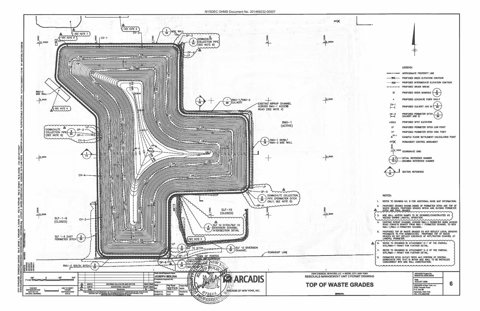
NYSDEC OHMS Document No. 201469232-00007

NYSDEC OHMS Document No. 201469232-00007

NYSDEC OHMS Document No. 201469232-00007

NYSDEC OHMS Document No. 201469232-00007

NYSDEC OHMS Document No. 201469232-00007

NYSDEC OHMS Document No. 201469232-00007

NYSDEC OHMS Document No. 201469232-00007
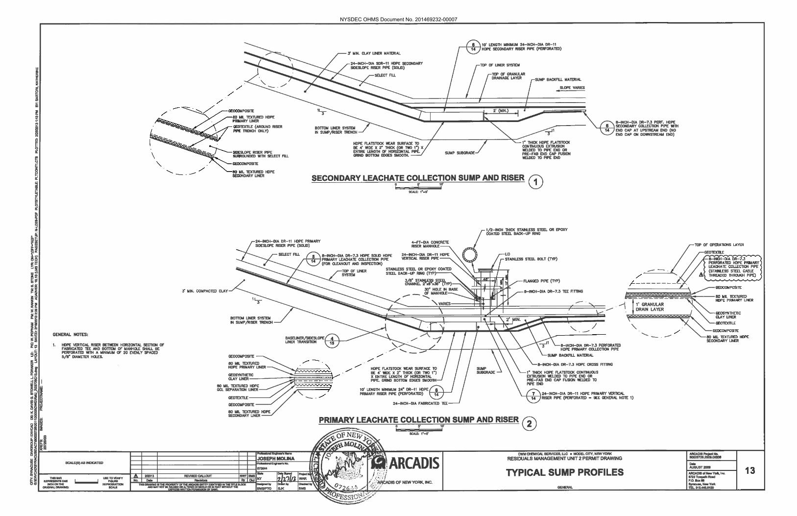
NYSDEC OHMS Document No. 201469232-00007

NYSDEC OHMS Document No. 201469232-00007

NYSDEC OHMS Document No. 201469232-00007

NYSDEC OHMS Document No. 201469232-00007

NYSDEC OHMS Document No. 201469232-00007
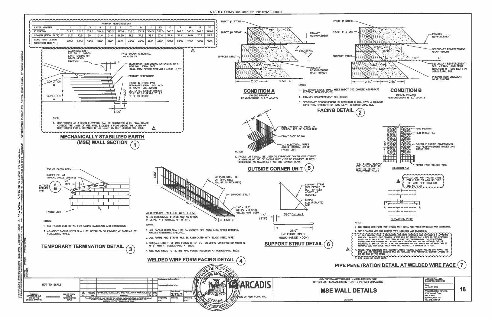
NYSDEC OHMS Document No. 201469232-00007

NYSDEC OHMS Document No. 201469232-00007

NYSDEC OHMS Document No. 201469232-00007
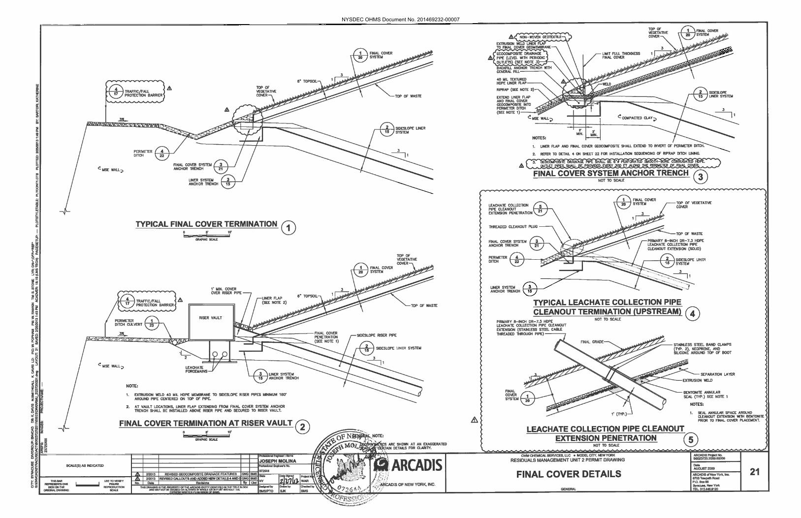
NYSDEC OHMS Document No. 201469232-00007

NYSDEC OHMS Document No. 201469232-00007
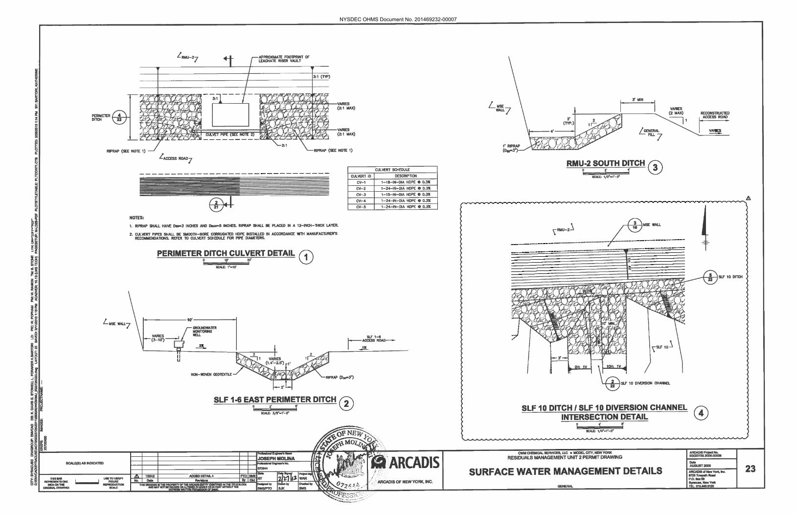
NYSDEC OHMS Document No. 201469232-00007

NYSDEC OHMS Document No. 201469232-00007

NYSDEC OHMS Document No. 201469232-00007
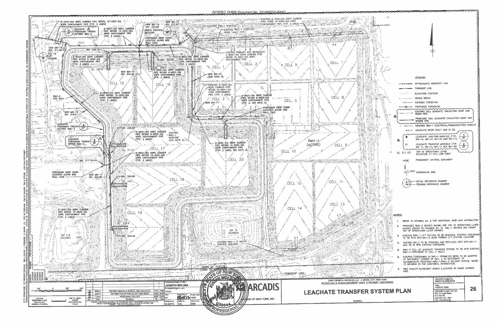
NYSDEC OHMS Document No. 201469232-00007

NYSDEC OHMS Document No. 201469232-00007

NYSDEC OHMS Document No. 201469232-00007

NYSDEC OHMS Document No. 201469232-00007

NYSDEC OHMS Document No. 201469232-00007

NYSDEC OHMS Document No. 201469232-00007

NYSDEC OHMS Document No. 201469232-00007

NYSDEC OHMS Document No. 201469232-00007

NYSDEC OHMS Document No. 201469232-00007

NYSDEC OHMS Document No. 201469232-00007

NYSDEC OHMS Document No. 201469232-00007

Appendix A
Geotechnical Investigations
NYSDEC OHMS Document No. 201469232-00007

Appendix A-1
Report Entitled Selection of Soil Properties for Geotechnical Evaluation of RMU-2 Design (P.J. Carey & Associates, PC, August 2009, Revised February 2013)
NYSDEC OHMS Document No. 201469232-00007

PERFORMEDFORCWMAUGUST2009–REVISED2/2013
APPENDIXA‐1SelectionofSoilProperties
For GEOTECHNIAL EVALUATION OF RMU‐2 DESIGN
PREPARED BY P.J. CAREY & ASSOCIATES, PC
Revised 2‐2013
NYSDEC OHMS Document No. 201469232-00007

Appendix A-1
TA B L E O F C O N T E N T S
1 INTRODUCTION ............................................................................................................................................................................... 1
1.1 INFORMATION REVIEWED ................................................................................................................................................................. 1 1.2 PURPOSE OF THE REVIEW ....................................................................................................................................................... 1 1.3 STRUCTURE OF APPENDIX A-1 ........................................................................................................................................................ 2
2 GLACIOLACUSTRINE CLAY CONSOLIDATION PROPERTIES ................................................................................ 3
2.1 EVALUATION OF ONE DIMENSIONAL CONSOLIDATION TEST RESULTS ........................................................................................ 3 2.1.1 Maximum Past pressure ....................................................................................................................................................... 3 2.1.2 Compression and Recompression IndiCies ....................................................................................................................... 3 2.1.3 Apparent permeability .......................................................................................................................................................... 3
2.2 AVAILABLE TESTS .............................................................................................................................................................................. 4
3 PERMEABIILTY AND DEFORMATIONAL PROPERTIES OF NON-GC STRATA ................................................. 6
3.1 GENERAL ............................................................................................................................................................................................ 6 3.2 PERMEABILITY AND DRAINAGE ....................................................................................................................................................... 6 3.3 DEFORMATION MODULI ..................................................................................................................................................................... 7
3.3.1 One Dimensional settlement of subgrade Calculations ................................................................................................... 7 3.3.2 Two dimensional time rate of consolidation....................................................................................................................... 7
4 SOIL MATERIAL SHEAR STRENGTHS .................................................................................................................................. 9
4.1 GLACIOLACUSTRINE CLAY .............................................................................................................................................................. 9 4.1.1 General ................................................................................................................................................................................... 9 4.1.2 Drained Shear Strength ........................................................................................................................................................ 9 4.1.3 Undrained Shear Strength – Static Conditions ................................................................................................................ 10 4.1.4 Undrained Shear Strength – Seismic Conditions ............................................................................................................ 12
4.2 UPPER GLACIAL TILL (UGT) ......................................................................................................................................................... 13 4.3 STRUCTURAL FILL ............................................................................................................................................................................ 13
4.3.1 Drained Shear Strength ...................................................................................................................................................... 14 4.3.2 Undrained shear strength ................................................................................................................................................... 14
5 LANDFILL MATERIAL SHEAR STRENGTHS ................................................................................................................... 15
5.1 WASTE .............................................................................................................................................................................................. 15 5.2 BOTTOM LINER ................................................................................................................................................................................ 15 5.3 SIDE SLOPE LINER ............................................................................................................................................................................ 16 5.4 COMPACTED CLAY LINER .............................................................................................................................................................. 16
6 MATERIAL PROPERTY SUMMARY ...................................................................................................................................... 17
FIGURES Figure 1 Permeability of GC Derived from Consolidation Tests Figure 2 Permeability of GC Derived from Consolidation Tests with OCR< 2 Figure 3 UU Shear Strength of Structural Fill Figure 4 R based Undrained Strength of Structural Fill ATTACHMENTS Attachment 1 Golder Figures for GSS from 2002 Attachment 2 Calculation of k from 1 Dimensional Consolidation Tests on GC Attachment 3 Plots of Consolidation test data for MPP and Compression Indices
NYSDEC OHMS Document No. 201469232-00007

APPENDIX A
Attachment 4 Table 1 from Golder Associates 2009 Annual Groundwater Interpretation Report Attachment 5 Average N values from Test Borings by Stratum Attachment 6 Evaluation of Drained Strength Parameters from CIU Testing on GC Attachment 7 Determination of SHANSEP Parameters for GC Attachment 8 Evaluation of Strength Parameters from Testing of Structural Fill
.
NYSDEC OHMS Document No. 201469232-00007

APPENDIX A-1 1
1 INTRODUCTION
1.1 INFORMATION REVIEWED
The CWM site has had numerous subsurface investigations, laboratory testing programs and quality control tests performed for the design, evaluation and construction certification of previous landfills. In addition, test borings and laboratory testing was performed specifically for the RMU-2 facility design. A review of the pertinent geotechnical information was performed to select design parameters for the settlement and stability analyses that were performed in support of the RMU-2 design. This review included the following data sources, many of which have been previously submitted to the NYDEC in support of previous design and permit activities:
Test Borings performed by others within the CWM site limits adjacent to and within the limits of RMU-2
Summary of Stratigraphic Unit Typical Index Property and Hydraulic Conductivity Values, Annual Groundwater Interpretation Report, Golder Associates, February 2009 (TABLE 1)
Subsurface Investigation Report for SCA – Secure Landfill #13 performed by Empire (1988)
RMU-1 Laboratory Testing performed by Empire (1990)
“Peer Review Panel Report, Shear Strength Evaluation for Slope Stability Analyses, RMU-1, Model City Treatment, Storage and Disposal Facility, Model City, New York”, by Koerner, Gilbert, Stark, Adams, dated March 2001.
Geotechnical Investigation for RMU-2 12/18/02 by Golder Associates
Laboratory Testing on Structural Fill Samples for RMU-2 performed by Geotechnics, (2009)
Laboratory Testing on Samples of Glaciolacustrine Clay for RMU-2 performed by GeoTesting Express (2013)
This information, with the exception of the boring logs and the Peer Review Panel Report are provided in other parts of Appendix A for convenience. Computations and analyses of the data performed by P. J. Carey & Associates, PC (PJCA) are contained in this document as figures, tables or attachments.
1.2 PURPOSE OF THE REVIEW
The purpose of this review was to allow the selection of consolidation properties, permeability, drained and undrained shear properties and moduli that were needed to perform the various analyses for the project. The collection of additional test data since the design of RMU-1 and the fact that tools used for the analyses performed for RMU-2 require different parameter sets than used for some of the
NYSDEC OHMS Document No. 201469232-00007

APPENDIX A-1 2
previously performed analyses resulted in the need for an overall review of parameters assigned to various strata for use in analyses.
1.3 STRUCTURE OF APPENDIX A-1
This appendix is separated into sections dealing with
Consolidation Properties for the Glaciolacustrine Clay (GC)
Permeability and Deformational Properties for Non-GC materials
Soil Materials Shear Strength (both drained, undrained static, and undrained seismic)
Landfill Material Shearing Properties
A summary of parameters adopted for use in the analysis is presented at the end of Appendix A-1. Properties not listed above are covered in the individual sections of the design appendix covering the design aspect requiring the property.
NYSDEC OHMS Document No. 201469232-00007

APPENDIX A-1 3
2 GLACIOLACUSTRINE CLAY CONSOLIDATION PROPERTIES
2.1 EVALUATION OF ONE DIMENSIONAL CONSOLIDATION TEST RESULTS
2.1.1 MAXIMUM PAST PRESSURE
The apparent maximum past pressure (mpp) can be estimated using the plots of void ratio vs log of pressure plots. There are a number of methods normally utilized for this determination. The most popular of these (Casagrande Construction) is significantly impacted by sample disturbance and poor fit initial snugness in the oedometer ring resulting in lower estimates of the mpp. Senol and Saglamer1 reported a method of plotting accumulated strain energy versus log of pressure that was found to represent a significant improvement over the Casagrande Construction and Schmertmann methods. This method was used to estimate the mpp for each of the one dimensional compression tests available.
2.1.2 COMPRESSION AND RECOMPRESSION INDICIES
Using plots of either void ratio versus log of pressure or strain versus log of pressure, idealized plots of strain or void ratio versus log pressure were constructed as follows:
Extend the test curve to a void ratio or strain equivalent to 0.42 e0
Create a line running from e0, σ'v parallel to the recompression portion of the curve, to the maximum past pressure.
Connect the point at 0.42 e0 to the point above and then compute compression coefficient (Cc )or the compression ratio (CR) depending on whether it is a e log p or strain log p plot
The values computed in the above fashion result in higher maximum past pressures and higher compression indices. The recompression properties are typically unchanged from previously reported values.
2.1.3 APPARENT PERMEABILITY
Time rate of consolidation determinations for RMU-2 require the determination of the permeability of the GC to be assigned that will allow simulation of the consolidation properties of the clay, rather than the typical coefficient of consolidation used in one dimensional time rate of consolidation evaluations. The “k” value of the GC was determined in the normally consolidated range utilizing the definition of cv in Terzaghi’s consolidation theory. The calculation of the k values is presented in Attachment 2. Calculations were performed on the three one dimensional consolidation tests performed by Golder in 2002 and reported in Appendix A-2. The resulting values are presented graphically in Figure 1. Values of k associated with overconsolidation ratios (OCR) of less than 2 are presented in Figure 2. The relationship derived using the values with OCRs of less than 2 was used for analysis in the project. Time rates of 1 “Aykut Senol and Ahmet Saglamer, “Determination of Pre-consolidation Pressure with New, “Strain-Energy-Log Stress” Method”, EJGE Paper 2000-015.
NYSDEC OHMS Document No. 201469232-00007

APPENDIX A-1 4
consolidation for higher OCR values in the test are not considered appropriate for use in field predictions, as they are heavily influenced by the time dependent deformation responses not controlled by permeability. A conductivity ratio (kv/kh) of 1 was assumed for the clay layers to be conservative. Typically, the horizontal permeability is higher than the vertical permeability for lacustrine deposits.
2.2 AVAILABLE TESTS
One consolidation test from the RMU-1 Empire testing and 3 consolidation tests performed by Golder Associates from samples obtained from the SB-02 series borings reported in Appendix A-2 were available to review and determine the compression characteristics of the GC materials. It should be noted that the e0 , compression indices and other results presented may vary from those reported by the testing lab. Reasons for this may be a difference of interpretation or use of a laboratory available specific gravity or moisture content in lieu of an assumed or in some cases incorrect value used in the original lab report. The resulting values of e0, Recompression ratio (RR = Cr/1+e0 ), Compression Ratio (CR = Cc/1+e0 ) and maximum past pressure (MPP) are presented below. Plots of the laboratory data used to obtain the information in the table below are presented in Attachment 3
Boring Depth (ft) e0 MPP
(tsf)
RR CR
B-6 25-27 0.826 2.8 0.032 0.225
SB 02 3A 14-16 0.492 3.3 0.016 0.0945
SB 02 3A 28-30 0.606 4 0.015 0.186
SB 02 2A 28-30 1.153 3.0 0.013 0.180
Values Applied to 1-D Baseliner Settlement Analysis – Conservatively Chosen
Lightly Overconsolidated GC
3 or 4 tsf whichever is less
0.015 0.2
Overconsolidated GC
OCR= 6 or 6 tsf, whichever is less
0.008 0.08
Note that reduced values were utilized for the overconsolidated GC in the 1D analysis given that the thickness of the layer was conservatively limited to 2 feet.
NYSDEC OHMS Document No. 201469232-00007

APPENDIX A-1 5
Based on the above listed results the following values were chosen for use in the analysis in the two dimensional time rate of loading analyses, weighting the SB results more heavily than the B-6 values
Parameter Lightly Overconsolidated GC Overconsolidated GC
e0 1.0 0.5
Cc 0.322 0.141
Cr 0.03 0.023
OCR* 4 6
λ 0.14 0.060
κ 0.013 0.01
κ = Cr /2.303 , λ = Cc /2.303 and are parameters for the modified cam clay model
* the OCR was applied to the excavated state so it is higher than the in situ OCR
NYSDEC OHMS Document No. 201469232-00007
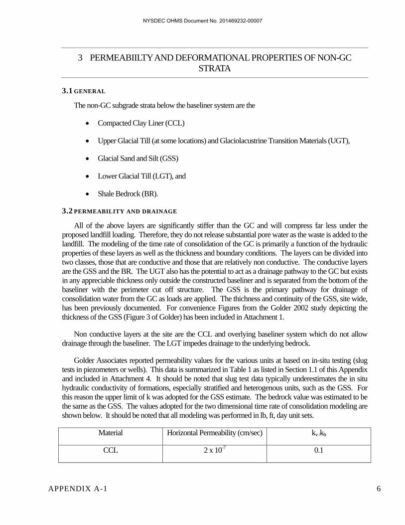
APPENDIX A-1 6
3 PERMEABIILTY AND DEFORMATIONAL PROPERTIES OF NON-GC STRATA
3.1 GENERAL
The non-GC subgrade strata below the baseliner system are the
Compacted Clay Liner (CCL)
Upper Glacial Till (at some locations) and Glaciolacustrine Transition Materials (UGT),
Glacial Sand and Silt (GSS)
Lower Glacial Till (LGT), and
Shale Bedrock (BR).
3.2 PERMEABILITY AND DRAINAGE
All of the above layers are significantly stiffer than the GC and will compress far less under the proposed landfill loading. Therefore, they do not release substantial pore water as the waste is added to the landfill. The modeling of the time rate of consolidation of the GC is primarily a function of the hydraulic properties of these layers as well as the thickness and boundary conditions. The layers can be divided into two classes, those that are conductive and those that are relatively non conductive. The conductive layers are the GSS and the BR. The UGT also has the potential to act as a drainage pathway to the GC but exists in any appreciable thickness only outside the constructed baseliner and is separated from the bottom of the baseliner with the perimeter cut off structure. The GSS is the primary pathway for drainage of consolidation water from the GC as loads are applied. The thichness and continuity of the GSS, site wide, has been previously documented. For convenience Figures from the Golder 2002 study depicting the thickness of the GSS (Figure 3 of Golder) has been included in Attachment 1.
Non conductive layers at the site are the CCL and overlying baseliner system which do not allow drainage through the baseliner. The LGT impedes drainage to the underlying bedrock.
Golder Associates reported permeability values for the various units at based on in-situ testing (slug tests in piezometers or wells). This data is summarized in Table 1 as listed in Section 1.1 of this Appendix and included in Attachment 4. It should be noted that slug test data typically underestimates the in situ hydraulic conductivity of formations, especially stratified and heterogenous units, such as the GSS. For this reason the upper limit of k was adopted for the GSS estimate. The bedrock value was estimated to be the same as the GSS. The values adopted for the two dimensional time rate of consolidation modeling are shown below. It should be noted that all modeling was performed in lb, ft, day unit sets.
Material Horizontal Permeability (cm/sec) kv /kh
CCL 2 x 10⁻⁷ 0.1
NYSDEC OHMS Document No. 201469232-00007
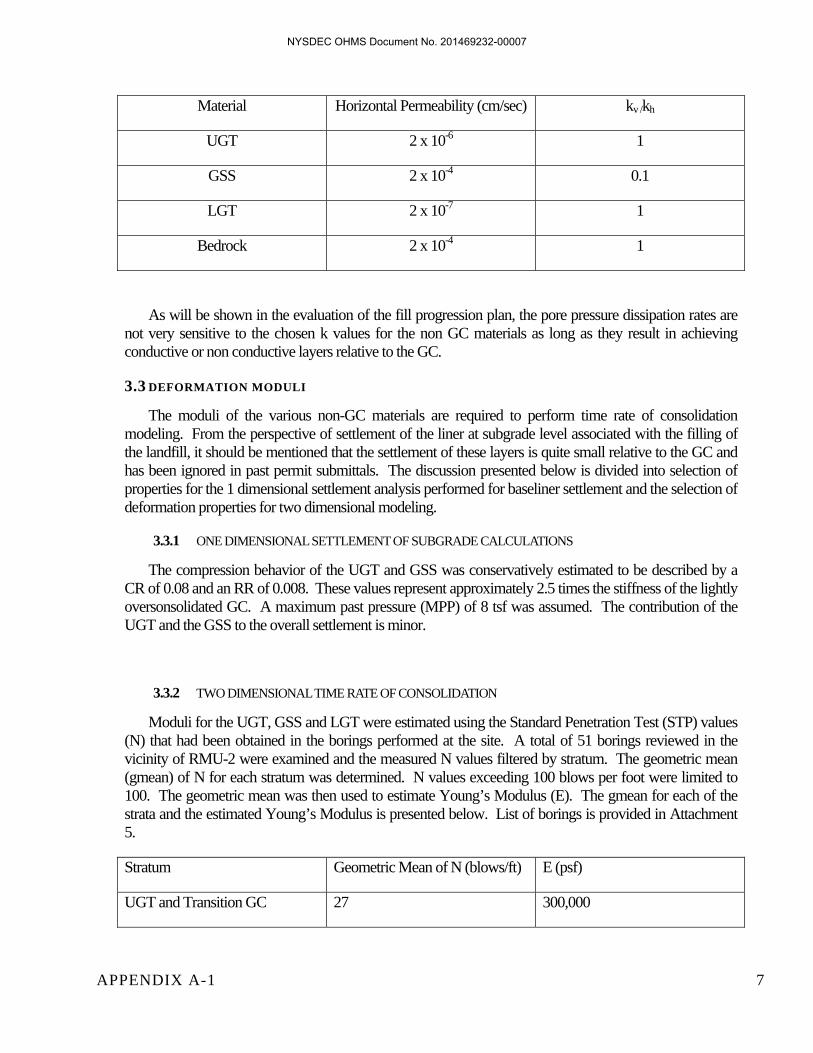
APPENDIX A-1 7
Material Horizontal Permeability (cm/sec) kv /kh
UGT 2 x 10⁻⁶ 1
GSS 2 x 10⁻⁴ 0.1
LGT 2 x 10⁻⁷ 1
Bedrock 2 x 10⁻⁴ 1
As will be shown in the evaluation of the fill progression plan, the pore pressure dissipation rates are not very sensitive to the chosen k values for the non GC materials as long as they result in achieving conductive or non conductive layers relative to the GC.
3.3 DEFORMATION MODULI
The moduli of the various non-GC materials are required to perform time rate of consolidation modeling. From the perspective of settlement of the liner at subgrade level associated with the filling of the landfill, it should be mentioned that the settlement of these layers is quite small relative to the GC and has been ignored in past permit submittals. The discussion presented below is divided into selection of properties for the 1 dimensional settlement analysis performed for baseliner settlement and the selection of deformation properties for two dimensional modeling.
3.3.1 ONE DIMENSIONAL SETTLEMENT OF SUBGRADE CALCULATIONS
The compression behavior of the UGT and GSS was conservatively estimated to be described by a CR of 0.08 and an RR of 0.008. These values represent approximately 2.5 times the stiffness of the lightly oversonsolidated GC. A maximum past pressure (MPP) of 8 tsf was assumed. The contribution of the UGT and the GSS to the overall settlement is minor.
3.3.2 TWO DIMENSIONAL TIME RATE OF CONSOLIDATION
Moduli for the UGT, GSS and LGT were estimated using the Standard Penetration Test (STP) values (N) that had been obtained in the borings performed at the site. A total of 51 borings reviewed in the vicinity of RMU-2 were examined and the measured N values filtered by stratum. The geometric mean (gmean) of N for each stratum was determined. N values exceeding 100 blows per foot were limited to 100. The geometric mean was then used to estimate Young’s Modulus (E). The gmean for each of the strata and the estimated Young’s Modulus is presented below. List of borings is provided in Attachment 5.
Stratum Geometric Mean of N (blows/ft) E (psf)
UGT and Transition GC 27 300,000
NYSDEC OHMS Document No. 201469232-00007

APPENDIX A-1 8
GSS 48 300,000
LGT >100 600,000
It should be noted that the assigned moduli are lower for the GSS and the LGT than those predicted by Callanan and Kulhawy as reported in Figure 5-13 of the EPRI Manual using the approximate relationship
605/ NpE a
Where pa is the pressure of one atmosphere and N60 is the N value assuming 60 % energy efficiency transmission. The predicted values for the GSS and LGT are approximately twice as high as assumed. The assumption of lower values is conservative in the calculation of time rate of consolidation, but not significantly so. In addition, the assigned E values were not increased with increasing confining load as would be done if a more refined analysis of the settlement of these layers were warranted. An increase in modulus roughly proportional to the square root of the increase in effective stress associated with loading of the landfill would be anticipated.
All other layers were assigned modulus values but were not involved in release of consolidation water so the value chosen was not significant to the analysis.
NYSDEC OHMS Document No. 201469232-00007

APPENDIX A-1 9
4 SOIL MATERIAL SHEAR STRENGTHS
4.1 GLACIOLACUSTRINE CLAY
4.1.1 GENERAL
A number of consolidated undrained triaxial compression tests have been performed on samples of the Glaciolacustrine Clay (GC) at this site. Testing has been performed by several investigators and the results have been analyzed to allow both drained and undrained strength envelopes to be chosen. The evaluation and selection of the various strength parameters for use in the analyses is presented subsequently.
4.1.2 DRAINED SHEAR STRENGTH
Three Consolidated Undrained Triaxial Compression tests (CIU) were performed by Empire in 1988 and reported by Donahue & Associates. In addition, three additional CIU tests were performed by Golder Associates in 2002, and are included in Appendix A-2. This data was analyzed by PJCA to allow drained strength assignments to be made for both the overconsolidated crust and softer lightly overconsolidated portions of this stratigraphic unit. Of the six tests, one, SB 02-4 @ 28-30 ft depth represented useable data on the lightly over consolidated GC. Two of the Golder tests on other lightly over consolidated clay appear to have experienced leakage during the shear phase of the test and did not result in useful data. The data from the three Empire tests and the aforementioned Golder test result were evaluated for fit to a curvilinear model that has shown to provide a closer prediction over the widest stress range of drained soft clay behavior:
m
kPa n
kPaTannq
1
100100
This expression predicts a zero strength at zero normal stress and a gradually diminishing secant φ' with increasing stress. The results from the four CIU on the lightly overconsolidated GC were well described by a φ'100kPa= 28.77°, and an m of 0.853. Details of the data fitting and plots of the test data versus the q predicted are presented in Attachment 6. This model of drained strength description was adopted along with a strength modifying function to account for the lower shear strength on near horizontal shear planes. The use of the modifier function, named “clay ellipse staticshear” and depicted below, reduces the effective φ'100kPa on horizontal planes to ~21°. This reduction in strength allows for the possible presence of lower strength horizontal beds that have been found in similar GC deposits elsewhere in the north New York Great Lake Basin.
NYSDEC OHMS Document No. 201469232-00007

APPENDIX A-1 10
Over consolidated portions of the GC were found to have much higher shear strengths, as reflected in SB 02-04 @12 to 14 feet, where the drained strength was described by a φ'=31.0° and c' = 243 psf. An evaluation of the test data is provided in Attachment 6
4.1.3 UNDRAINED SHEAR STRENGTH – STATIC CONDITIONS
Unconsolidated Undrained (UU) triaxial compression tests, CIU triaxial compression tests and vane shear tests have been performed at the site. Within the limits of RMU-2 , fifteen (15) UU tests were performed by Golder on “undisturbed” samples of GC. These results along with the vane shear tests performed in the SB 02 borings (three tests total) and the results from the three 1988 Empire CIU tests were used along with the basin SHANSEP equation
Su'v
S OCRm
to determine the S and m coefficients along with a single selection of maximum past pressure, to allow the over consolidation ratio to be automatically approximated by the stability software. Details of the calculation are presented along with predicted and measured strengths in Attachment 7. Representation of the data was achieved with the following parameters
clay ellipse staticshear
Mod
ifier
Fac
tor
Inclination (°)
0.65
0.7
0.75
0.8
0.85
0.9
0.95
-20-40-60 0 20 40 60
NYSDEC OHMS Document No. 201469232-00007

APPENDIX A-1 11
S of 0.34,
m=0.7, and
Maximum Past Pressure = 5000 psf.
A value of S of 0.34 is used in the stability analysis.
The Su of the overconsolidated GC is modeled in utilizing the above parameters with the exception that the Maximum Past Pressure is increased to 8000 psf, consistent with the consolidation test values.
Direct simple shear tests (DSS) were performed on undisturbed samples of the lightly consolidated GC. Shelby tube samples, obtained from SB12-01 and SB12-02. The two series of test were performed, one a CK0DSS and a second with static shear force added during consolidation equal to 0.2 x v. The test results, provided in Attachment 7. The test results show that the ratio of Su/v is 0.21 to 0.19 under CK0DSS conditions and increases by approximately 26% to 0.24 at the highest vertical stress (6 tsf) when the static shear stress of 0.2 v was applied. It should be mentioned that the testing apparatus utilized by GeoTesting Express did not allow slow steady vertical or shear load application during the consolidation stage of the testing. The loads were applied in discrete increments that resulted in actually higher shear to vertical stress ratios during a significant portion of each load step. This step loading produced greater horizontal shear strain that a gradual continuous loading would have produced and, therefore, reflects a shear strength that is considerably post peak and conservative.
The DSS testing program results are incorporated into the strength assignment for the GC materials (both lightly overconsolidated and overconsolidated GC, through the use of a directional modifier function. Two functions are developed, “clay ellipse” to reflect conditions where the stress state in the soils are best described by k0 conditions and the “clay ellipse static shear” to reflect conditions where static shear stresses where the construction of the waste mass or perimeter berm has resulted in effective stresses that include static shear during the consolidation. In the future, DSS testing with static shear during consolidation applied more gradually, better reflecting field conditions, The testing of this kind will likely result in an increase in the Su/v ratio. At such time the directional modifier functions should be modified. The two functions are depicted below.
NYSDEC OHMS Document No. 201469232-00007
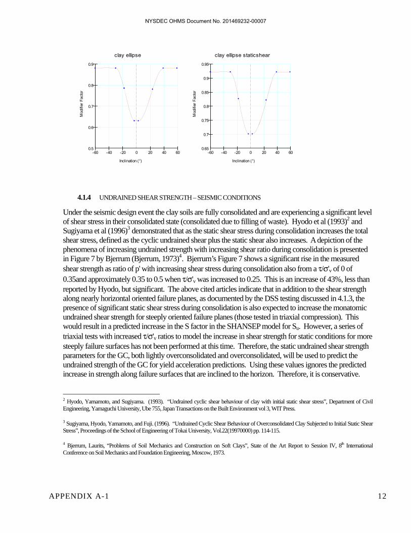
APPENDIX A-1 12
4.1.4 UNDRAINED SHEAR STRENGTH – SEISMIC CONDITIONS
Under the seismic design event the clay soils are fully consolidated and are experiencing a significant level of shear stress in their consolidated state (consolidated due to filling of waste). Hyodo et al (1993)2 and Sugiyama et al (1996)3 demonstrated that as the static shear stress during consolidation increases the total shear stress, defined as the cyclic undrained shear plus the static shear also increases. A depiction of the phenomena of increasing undrained strength with increasing shear ratio during consolidation is presented in Figure 7 by Bjerrum (Bjerrum, 1973)4. Bjerrum’s Figure 7 shows a significant rise in the measured shear strength as ratio of p' with increasing shear stress during consolidation also from a /'v of 0 of 0.35and approximately 0.35 to 0.5 when /'v was increased to 0.25. This is an increase of 43%, less than reported by Hyodo, but significant. The above cited articles indicate that in addition to the shear strength along nearly horizontal oriented failure planes, as documented by the DSS testing discussed in 4.1.3, the presence of significant static shear stress during consolidation is also expected to increase the monatomic undrained shear strength for steeply oriented failure planes (those tested in triaxial compression). This would result in a predicted increase in the S factor in the SHANSEP model for Su. However, a series of triaxial tests with increased /'v ratios to model the increase in shear strength for static conditions for more steeply failure surfaces has not been performed at this time. Therefore, the static undrained shear strength parameters for the GC, both lightly overconsolidated and overconsolidated, will be used to predict the undrained strength of the GC for yield acceleration predictions. Using these values ignores the predicted increase in strength along failure surfaces that are inclined to the horizon. Therefore, it is conservative. 2 Hyodo, Yamamoto, and Sugiyama. (1993). “Undrained cyclic shear behaviour of clay with initial static shear stress”, Department of Civil Engineering, Yamaguchi University, Ube 755, Japan Transactions on the Built Environment vol 3, WIT Press.
3 Sugiyama, Hyodo, Yamamoto, and Fuji. (1996). “Undrained Cyclic Shear Behaviour of Overconsolidated Clay Subjected to Initial Static Shear Stress”, Proceedings of the School of Engineering of Tokai University, Vol.22(19970000) pp. 114-115.
4 Bjerrum, Laurits, “Problems of Soil Mechanics and Construction on Soft Clays”, State of the Art Report to Session IV, 8th International Conference on Soil Mechanics and Foundation Engineering, Moscow, 1973.
clay ellipse
Mod
ifier
Fac
tor
Inclination (°)
0.5
0.6
0.7
0.8
0.9
-20-40-60 0 20 40 60
clay ellipse staticshear
Mod
ifier
Fac
tor
Inclination (°)
0.65
0.7
0.75
0.8
0.85
0.9
0.95
-20-40-60 0 20 40 60
NYSDEC OHMS Document No. 201469232-00007

APPENDIX A-1 13
Often the a 20% reduction the shear strength of clays is applied to the static shear strength results (0.8 × Su). This reduction applies to a test run at the same speed of shearing and assumes approximately 15 cycles to failure (Idriss and Boulanger)5. The design earthquake magnitude for this site is 5.6 which is predicted to be only 5 cycles, as opposed to 15 cycles in a 7.5 magnitude event (Table 3-3 in Kramer)6. This results in less potential for shear strength loss for the clay strength under the site seismic design event compared to the standard 15 cycles normally assumed. As depicted in Figure 25 in Idriss and Boulanger a predicted ratio of the cyclic strength divided by Su is 1.2 for 5 strong motion cycles. This would result in multiplier or 0.96 (1.2x0.8) being applied to the monatomic undrained shear strength. A copy of Figure 25 is included in Attachment 7. In addition to magnitude impacts on the strength, the presence of significant static shear, at lateral acceleration levels at this site, eliminates the any shear stress reversals during the seismic design event. The lack of stress reversals will reduce any pore pressure build up during the seismic design event.
All of the above factors considered, it is considered conservative to use the undrained strength parameters for the GC materials developed for the static conditions without reduction, applying the directional modifier associated with static shear stress presence (clay ellipse staticshear) for seismic conditions at this site.
4.2 UPPER GLACIAL TILL (UGT)
The CIU test performed on the sample from 10-12ft in SB 02-04 was used to estimate the shear properties of the UGT. A least squares linear fit of the test result provides a φ' = 31° and c' of 184 psf. This result is consistent with low plasticity and relatively high N values for this stratum obtained in this stratum. A φ' = 31° and c' of 150 psf were adopted for the design. A total unit weight of 125 pcf was adopted for design.
4.3 STRUCTURAL FILL
Two series of CIU tests and 12 UU tests were performed on samples of potential structural fill obtained from test pits on site. The goal of these tests was to establish the likely strength properties of materials that would be used as on site borrow. It should be mentioned that quality control testing will be performed on the structural fill, therefore the testing represents an expectation of strengths that can be obtained. The testing was performed by Geotechnics, of Pittsburgh, PA. Testing requirements were selected by PJCA. The results of the tests are provided in Appendix A-3.
5 Idriss, I. M., and Boulanger, R. W. (2004). "Semi-empirical procedures for evaluating liquefaction potential during earthquakes." Proc., 11th International Conference on Soil Dynamics and Earthquake Engineering, and 3rd International Conference on Earthquake Geotechnical Engineering, D. Doolin et al., eds., Stallion Press, Vol. 1, 32-56.
6 Kramer, S.L. (1996). Geotechnical Earthquake Engineering, Prentice Hall, Inc., Upper Saddle River, New Jersey,
NYSDEC OHMS Document No. 201469232-00007

APPENDIX A-1 14
4.3.1 DRAINED SHEAR STRENGTH
The two samples with the higher plastic index (PI) were selected to be tested in CIU triaxial compression tests with pore pressure measurements. The two tests provided the following results Sample φ' c' (psf) FAC Pond WEST 28.7 196 SULLY’s 26.4 363
The normal stress range for the proposed berms that will be constructed of structural fill is from 0 to 4000 psf. For this pressure range the FAC Pond West sample represents the weaker of the two materials and was adopted as the design strength. For stress above 4000 psf the Sully material would represent the lower strength material. A design total unit weight of 128 pcf was used for drained analyses, based on the compacted unit weights measured in the moisture content/density testing performed. If a normalized φ' model is used the average values obtained for both data sets was φ'100kPa = 33.44 °and m = 0.878. Evaluation of the test results by PJCA is presented in Attachment 8.
4.3.2 UNDRAINED SHEAR STRENGTH
The undrained testing of 12 compacted fill specimens was performed to allow an undrained strength envelope to be approximated for the structural fill. The resulting values of UU from the 12 tests are plotted in Figure 3. As was expected the UU tests show some dependence on confining stress, as they are only partially saturated. The dependence was greatest for the FAC pond 3 East sample which was non plastic. The confining stress levels vary widely within the perimeter berm even for consistent levels of vertical effective stress. Therefore a conservative envelope was utilized for the design calculations for undrained conditions associated with vehicle loadings on the MSE wall. The design envelope is included in Figure 3
In addition to the short term undrained strength envelope of 2000 psf for the compacted soils a longer term R envelope for use in the analysis of equipment loadings at times into the future was developed from the CIU testing on the Sully’s material. This envelope is depicted in Figure 4. The stress parameters to be assigned for cohesive structural fill for undrained conditions occurring at times greater than 3 months following completion of berm construction is φ = 26.3° and c of 353 psf.
NYSDEC OHMS Document No. 201469232-00007

APPENDIX A-1 15
5 LANDFILL MATERIAL SHEAR STRENGTHS
The shearing properties of the landfill materials;
Waste
Baseliner
Sideslope Baseliner
Compacted Clay Liner (CCL)
were examined in detail by a panel of experts commissioned by CWM in 2000. The panel completed its evaluation in March of 2001 and issued the report referenced in Section 1 of this Appendix. The report has been submitted to the NYDEC as a part of ongoing work at the site. PJCA has reviewed this report in detail and agrees with the recommendations pertaining to the landfill materials. A summary of the properties recommended by the report is presented below. It should be noted that CWM can, based on testing of new materials that could be incorporated into the lining systems, adopt different shearing properties for design in the future if desired. The liner materials are purchased or engineered products that can be modified. The adoption of the recommendations assumes that CWM can at a minimum achieve the properties with respect to shear resistance, which they have already demonstrated.
5.1 WASTE
A shear strength of waste materials described by a φ' =30 degrees was adopted based on the Peer Review Panel report. This recommendation is consistent with the behavior observed at the site during the operations of RMU-1 and earlier units, where slopes of 2H:1V have been created and performed without incident for a significant time period, clearly indicating the overall shear strength of the waste is well in excess of the original shear strength described by an effective friction angle (φ') of 24°.
5.2 BOTTOM LINER
The recommended shear strength versus normal load function presented in the Peer Review Panel report was adopted for use in the analysis. The graph below represents the function used in the Geoslope analyses. The Peer Review Panel based these strengths on large displacement test values. Therefore no further reduction for deformation potential need be applied. CWM intends to use similar materials for the bottom liner system as have been tested for RMU-1. Therefore, this strength envelope is applicable for application to RMU-2.
NYSDEC OHMS Document No. 201469232-00007

APPENDIX A-1 16
5.3 SIDE SLOPE LINER
A large displacement shear strength of the side slope liner materials described by a φ' =13 degrees was adopted based on the Peer Review Panel report. It should be noted that this recommendation does not reflect the higher shear strengths that are typically measured on these materials at normal stress levels below 1000 psf. The recommended value of shear strength for the side slope liner material should not be any different from that obtained for the final cover system at stresses below 1000 psf.
5.4 COMPACTED CLAY LINER
The Compacted clay liner (CCL) strength was adopted from the Peer Review Panel Report. This strength represented the large displacement shear and peak shear strength of the clay, as no significant strain softening was observed. The recommendation was q = n' x tan 10 ° +1000 psf.
Baseliner
Shea
r Stre
ss (p
sf)
Normal Stress (psf)
0
500
1000
1500
2000
2500
3000
3500
4000
4500
0 5000 10000 15000
NYSDEC OHMS Document No. 201469232-00007

APPENDIX A-1 17
6 MATERIAL PROPERTY SUMMARY
Material properties as assigned in the slope stability analysis are presented in the following table.
SUMMARY OF SHEAR STRENGTH PROPERTIES FOR STABILTY ANALYSIS
Soil Type Total Unit Weight (pcf)
Cohesion. (psf)
φ (degrees)
Other/Additional
Final Cover 125 27.5
Waste 111 0 30
Bottom Liner (Textured Liner)
120 N/A N/A See Baseliner Function Above
Side Slope Liner (Textured Liner System)
115 0 13
Compacted Clay Liner (CCL)
120 1000 10
Upper Till 125 150 31
Over Consolidated Glaciolacustrine Clay (OGC)
(Drained)
125 100 30
Lightly Over Consolidated Glaciolacustrine Clay (LOGC)
(Drained)
118 Normalized φ’ φ’100kPA = 28.7 °, m =.147 with anisotropic function
Glaciolacustrine Clay (Undrained)
115 N/A N/A SHANSEP Model S = 0.34m = 0.7 for static MPP=5000 psf
for LOGC MPP=8000 psf for OGC
with anisotropic functions
Glaciolacustrine Sand/Silt
135 N/A 34 (Considered Impenetrable in most analyses)
Lower Till (Considered Impenetrable)
N/A N/A N/A
Structural Fill (Drained)
128 195 28.7 For all analysis allowing failure within perimeter berm. Other strengths and weights were used for analyses not
allowing failure withing the berm mass
Structural Fill (Undrained)
130 2000 psf For Short Term conditions after initial construction
Structural Fill (Undrained)
130 353 26.3 Undrained conditions more than 3 months following construction
NYSDEC OHMS Document No. 201469232-00007

APPENDIX A-1 18
Notes:
1) Unit weights used in the above table are based on values consistent with the materials present on site. The above unit weights are the same as those used in previous calculations for the final cover and waste materials. Unit weights for the till, compacted clay liner and Glaciolacustrine clay are lower than previously used representing a slightly more conservative result than use of the previous values would provide. These lower values were used to be consistent with data gathered at other sites in a similar setting to this facility.
2) The liner system values have been reduced to the three materials presented above. These are the three critical materials or interfaces identified by the Peer Review Panel.
NYSDEC OHMS Document No. 201469232-00007