imer u.s.a. inc. hoist.pdf · - 5 - imer u.s.a. inc. pull up 650 working in safety to work in...
TRANSCRIPT

Machine serial N°
Manual Part. number 3229687 - 09/2011
IMER U.S.A. inc.PULL UP 650
R
INSTRUCTION MANUAL and PARTS LIST
Model 1140958
Write in the serial n° of your machine here.
MANUAL DE USO, MANTENIMIENTO y RECAMBIOS

- 2 -
IMER U.S.A. Inc.PULL UP 650
Thank-you for purchasing a PULL UP 650 from an Imer U.S.A. dealer. Your decision is an intelligent one.
There is no other hoist in the world which delivers the benefi ts and features of the PULL UP 650.
- High lifting speed
- High lifting capacity
- Pendant control with emergency button
- Trolley track with hand brake
- Wide track for more stability
- 24 V command control for greater safety
At Imer U.S.A. we continually search for ways to better serve our customers. Should you have an idea or thought to share with us regarding this product we would appreciate hearing from you. Our motto is "Tools and Services for the 21st Century" . We look forward to delivering the goods.
Thank you again for your purchase.
Mace T. Coleman, Jr.President, Imer U.S.A., Inc.
IMER EAST221 Westhampton PlaceCapitol Heights, MD 20743Tel 800 - 275 - 5463Fax 301 - 336 - 6687
- 3 -
IMER U.S.A. Inc.PULL UP 650
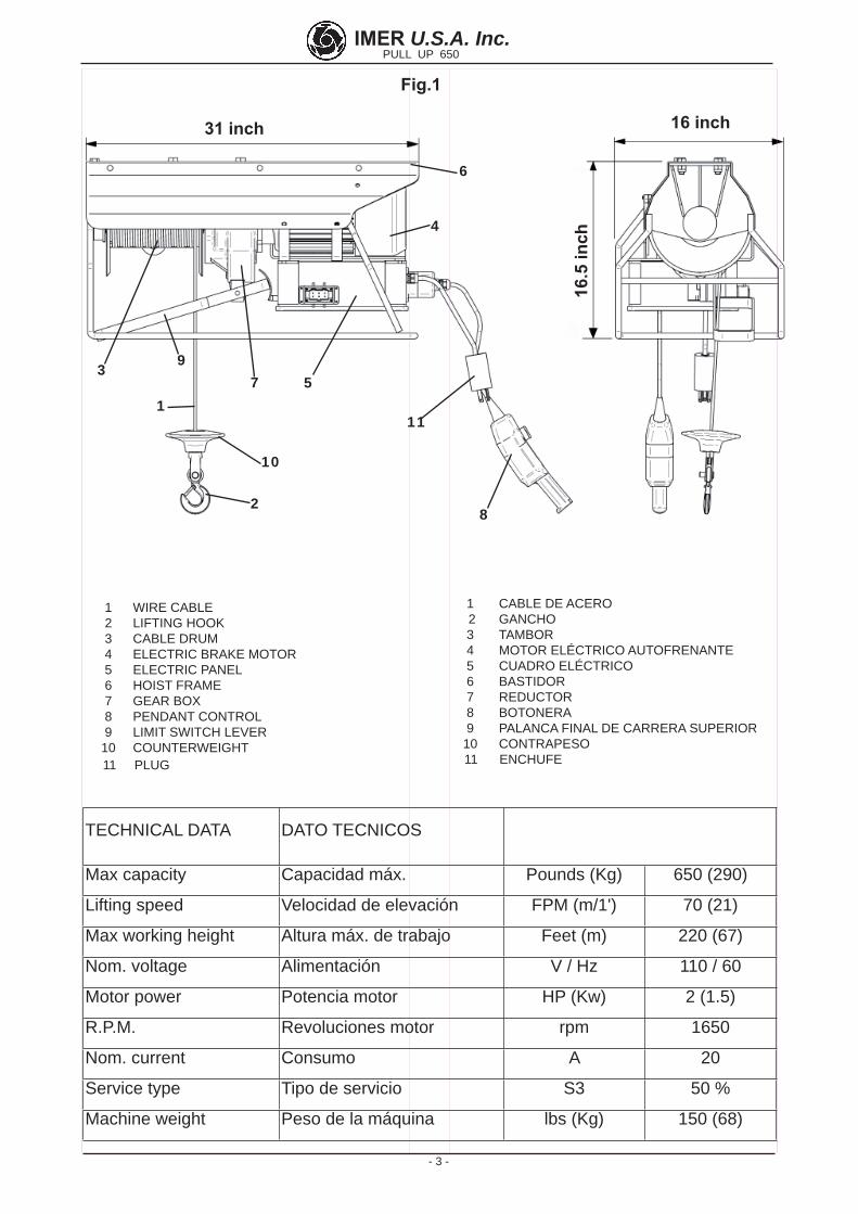
Fig.1
1 WIRE CABLE 2 LIFTING HOOK 3 CABLE DRUM 4 ELECTRIC BRAKE MOTOR 5 ELECTRIC PANEL 6 HOIST FRAME 7 GEAR BOX 8 PENDANT CONTROL 9 LIMIT SWITCH LEVER 10 COUNTERWEIGHT 11 PLUG
1 CABLE DE ACERO 2 GANCHO 3 TAMBOR 4 MOTOR ELÉCTRICO AUTOFRENANTE 5 CUADRO ELÉCTRICO 6 BASTIDOR 7 REDUCTOR 8 BOTONERA 9 PALANCA FINAL DE CARRERA SUPERIOR 10 CONTRAPESO 11 ENCHUFE
TECHNICAL DATA DATO TECNICOS
Max capacity Capacidad máx. Pounds (Kg) 650 (290)
Lifting speed Velocidad de elevación FPM (m/1') 70 (21)
Max working height Altura máx. de trabajo Feet (m) 220 (67)
Nom. voltage Alimentación V / Hz 110 / 60
Motor power Potencia motor HP (Kw) 2 (1.5)
R.P.M. Revoluciones motor rpm 1650
Nom. current Consumo A 20
Service type Tipo de servicio S3 50 %
Machine weight Peso de la máquina lbs (Kg) 150 (68)
3
6
1
2
4
57
8
9
10
31 inch 16 inch
16.5
inch
11

- 4 -
IMER U.S.A. Inc.PULL UP 650
Table of ContentsNOTE: Please read and understand this manual before beginning to operate this hoist.
1. GENERAL DESCRIPTION ............................................................................... 5
2. HOIST SUPPORTS ...................................................................................... 5
3. ASSEMBLY .............................................................................................. 6
4. CONNECTING TO THE ELECTRICAL SUPPLY ....................................................... 6
5. SET-UP AND SAFETY TESTS TO COMPLETE BEFORE USING YOUR HOIST ..................... 6
6. SAFETY WARNINGS AND OPERATING PRECAUTIONS ............................................. 6
7. MAINTENANCE .......................................................................................... 7
8. DISMANTLING .......................................................................................... 8
9 TRANSPORTATION AND STORAGE ................................................................. 8
10. TROUBLESHOOTING AND REPAIR .............................................................. 8
11. WHAT TO DO IF THE HOIST FAILS WHILE LIFTING A LOAD .................................. 8
Special attention must be given to warnings with this symbol.
Due to Imer U.S.A. 's commitment to Reasearch and Development,
specifi cations are subjectto change without notice.

- 5 -
IMER U.S.A. Inc.PULL UP 650
WORKING IN SAFETYTo work in complete safety, read the following instructions carefully before installing the hoist.
This operation and maintenance manual must be kept on site by the person in charge, i.e. the site foreman, and must always be available for consultation.The manual is to be considered an integral part of the machine and must be kept for future reference until the machine is disposed of. If it is damaged or lost, a replacement copy may be requested from the hoist manufacturer. Call IMER USA @ 800-275-5463.The manual contains important information regarding site pre-paration, installation, operation, maintenance, and ordering of spare parts. Nevertheless, the installer and the operator must both have adequate experience and knowledge of the machine prior to use.To guarantee the complete safety of the operator, safe operation and long life of equipment, follow the instructions in this manual carefully, and observe all safety standards currently in force for the prevention of accidents at work, with particular reference to suspended loads and fall equipment (use of suitable footwear and clothing, hard hats, safety harnesses, proper installation of railings around drops, etc.).
It is strictly forbidden to carry out any form of modifi ca-tion to the steel structure or working parts of the machine.IMER declines all responsibility for non-compliance with laws and standards governing the use of lifting equipment, in particular; unprogrammed use, defective power supply, lack of maintenance, unauthorised modifi cations, tampering with or damage to part or all of the equipment, and partial or total failure to observe the instructions contained in this manual.
1. GENERAL DESCRIPTION
ATTENTION: Use of lifting equipment requires care and skill. The machine must be operated by skilled and properly instructed personnel only.
1) The machine is designed to lift materials only and for use on building construction sites.
2) Carrying passengers and/or animals is prohibited.
3) The machine must not be used in potentially explosive atmospheres or underground.The machine consists of (go back to fi g. 1):Drum type winch fi tted to reduction gear shaft , wire cable (1), lift hook (2) and counterweight (10).Drum (3).Gearmotor consisting of an electric brake motor (4) and reduction gear unit (7).Electrical panel (5).UP position control lever (9).Hoist frame (6).The winch has a pendant control (8) which supplies the command controls at 24V.
2. HOIST SUPPORTS
Fig. 2 shows an assembly of the hoist with the monorail trestle, in this case it is necessary with the trolley.The trolley is assembled on the hoist with three bolts; tighten the three selfl ocking nuts nice and tight.The structure supporting the hoist trestle must bear the following stresses generated during operation (Fig. 3). IMER offers a wide range of supports (see fi gures 8-9-10-11-12) for use on building sites, designed to suitably transfer the stresses to the building structures.These forces - referring to support couplings - must be accounted for in calculations related to supporting structures (scaffolding, ceilings, etc.), made by a qualifi ed experienced technician.To install the various supports, follow the instructions which apply to each assembly.When using supports with load bearing capacities other than that of the hoist, the permissible load bearing capacity of the weakest element of the system must be prominently displayed, and must not be exceeded.
2.1 INSTALLING THE HOIST ON SITE
The area where the hoist lifts material must have a safety bar at least 3.5 ft. high and a lower foot stop. This prevents falls and also prevents people from leaning out into the lift run and being hit by material.
Fig. 2
scaffold mount trestle cod. 1191265
Hoistcod. 1140958
Track trolleyassemblycod. 1191060
Hand brake

- 6 -
IMER U.S.A. Inc.PULL UP 650
- Make sure that the lifting run is free from obstacles, and ensure that nobody can lean out into the hoistway from intermediate fl oors.- Cordon off the ground loading area to prevent interference with work.
3. ASSEMBLY (Fig.1)
1) Only competent, trained personnel may assemble and operate the hoist.Given the weight of the hoist, an appropriate number of personnel must be used for handling and installing it so as to avoid hazar-dous situations.2) The maximum working height (220 ft) corresponds to the ge-armotor position i.e. it is measured from drum.3) Mount the hoist on the trestle by inserting the trolley wheels (fi g. 2) into the monorail guides and release the handbrake.Prevent detachment of the hoist by fi tting, at the end of the trolley track, the end stop.For the rest, follow the instructions for the support.
- If the trolley does not fi t in the truck, check the measure shown in Fig. 4.1. If the measure is higher, the wheels have come out of the bearing housing. With a rubber hammer hit the 4 wheels as the arrows.4) Insert the pendant control plug in the electrical panel (5) and hook the spring clip of the steel cable onto the ring on the electric panel to avoid pulling on the electric cable.
The pendant control has 3 pushbuttons (Fig. 4.2):black: downwhite: upred: emergency stop.5) Release the hook.
4. CONNECTING TO THE ELECTRICAL SUPPLY
- Make sure that the supplied voltage is the same as that specifi ed on the dataplate fi xed to the hoist.- Also check that the voltage is within the range -5% to +5% of the nominal operating value.- The power cable must be fi tted with an overload circuit breaker or fuse and a RCCD , the ground wire must have the same cross-section as the power cable.The conductors must be dimensioned in proportion to both the operating current and their length to avoid voltage drops.You must always use at least a 10 gauge cord with this hoist. This hoist requires a dedicated 30 Amp 110 V circuit. The hoist will over heat and malfunction if this advice is not followed. Consult with a qualifi ed electrician and do it right!Do not use extension cords wound up on drums.- The power cable must be suitable for frequent handling and have an abrasion-resistant sleeve.- Insert the plug into the machine.- The hoist is now ready for testing.
5. SET-UP AND SAFETY TESTS TO COMPLETE BEFORE USING YOUR HOIST
- Warning! Testing must be carried out by qualifi ed ex-perienced personnel. Take all necessary safety precautions.
- Warning! The hoist must be tested before use.Before testing the hoist make sure that it has been correctly installed.1) Lower the unloaded cable to the lower loading position, and check that at the end of its travel three turns of cable remain on the drum.2) No-load test. Apply a small load (40 lbs) and run a complete up/down cycle.Test the up, down and emergency stop buttons, UP limit switch operation, correct rope winding onto the drum and motor brake operation.3) Load test. Load the hoist with its maximum admissible load. Run a complete up/down cycle to test the stability of the supports and the motor brake.After the test, check the support structure for failure and slippage and recheck that the drum is level (use a bubble level).4) The hoist is fi tted with a safety which stops travel at the UP (9).Do not depend on this safety to stop the hoist; release the control button to stop the hoist instead.
- IMPORTANT!! Limit switch activation can occur either due to incorrect working height or due to other problems which may prejudice correct hoist functioning. After the limit switch has been activated, the hoist installation and compo-nents must be checked (rope, drum, shaft etc.)On completion of testing, compile the test report with the date, installation check data and signature as well as any other com-ments (Tab. 1).
- In case of new installations and after every service, repeat the no-load (2) and load (3) tests described above.
6. SAFETY WARNINGS AND OPERATING PRECAUTIONS
-1) Never lift loads exceeding the capacity of the hoist.
- 2) Never allow persons to remain below suspended loads.
- 3) Never try to lift loads anchored to the ground (i.e. embedded posts, pilings, etc.).
- 4) Ensure that the load is securely connected to the lifting hook and also close the safety latch.
Fig. 4.2
Fig. 3
Fig. 4.1
10.2 " (260 mm)

- 7 -
IMER U.S.A. Inc.PULL UP 650
- Use only IMER original spare parts. - Check the motor brake every 6/7 days. - Ensure that the notices and decals on the machine are
prominently displayed and legible. - Keep the machine clean of dirt. - Check the operation of the UP position limit switche
at the start of each work shift. - Check the electrical cable at the start of every work
cycle for accidental damage.
7.1 WIRE CABLE
Only use new cables as specifi ed below, complete with certifi cate of conformity and identifi cation.External diameter : 1/4 inch (6 mm)Type : 133 wires (19x7) anti-spinMinimum breaking strain : 5700 lbs (26 kN)Length : 223 feet (68 m)Surface treatment : galvanised, greased.
The IMER reference number is given in the spare parts table.
7.1.1 REPLACING THE CABLE (Fig. 5)
The cable must be replaced by a qualifi ed service technician.Fig. 5.1: remove the hook (4) by unscrewing bolt (5).Remove the clamp (1), push on the wedge (2) and extract the cable from the block (3).Completely unwind the cable. Extract from the inside of the drum through the hole and slot. Remove it from inside the drum through the hole and slot. Insert the new cable in the hole and thread it through the slot in the drum tube. Tighten the clamp at the end, leaving about 1/2 inch of cable free (fi g. 5.2), and pull the cable until the clamp comes into contact with the inner wall of the drum.
Tension the cable for good con-tact with the drum surface (fi g. 5.3).Now wind on the cable in adjacent turns, one layer at a time.Insert the cable into the counterweight and the block (Fig. 5.4).Pass the cable back through the counterweight and the block.
Fig. 5.3
- 5) If the load requires accessories to be attached or hooked up, these must be certifi ed and approved (harnesses, ropes, slings, etc.). The weight of these accessories must be subtracted from the maximum capacity.
- 6) Ensure that no part of the load protrudes during the lifting process.
- 7) Before releasing the load, ensure that it is in a stable position.
- 8) A suspended load must never be detached by a sud-den release or by cutting the slings, this causes a backlash movement of the entire structure.
- 9) Never move hands or parts of the body near the hoist during operation, as this constitutes a risk of entrapment with the cable, with the risk of serious accidents.
- 10) Never move hands or parts of the body near the cable counterweight during the lifting process, as this constitutes a risk of crushing or pinching with the limit switch lever.
- 11) Avoid use in adverse weather conditions (strong winds or storms) as the load will not lift straight up.
- 12) There must be adequate lighting at the hoist and at the lifting and discharge positions.
- 13) Ensure that all guards and safety devices are in place and in working order.
- 14) During use, check that the cable unwinds correctly, turn after turn, without slackening or twisting, which can cause damage to the cable. If this occurs, unwind the rope and rewind it correctly keeping the cable properly tensioned at all times.
- 15) Ensure that the travel and work areas are free of obstacles throughout the lift height and take the necessary precautions to prevent persons from leaning out of interme-diate fl oors.
- 16) Clear the lower load area to prevent persons from being present during lifting.
- 17) Keep children at a safe distance from the hoist.
- 18) When the hoist is not in use, do not allow unautho-rised personnel access or operation.
- 19) Use of the hoist must be for straight up and down (do not exceed over 5° with respect to vertical angle).
- 20) Never move the elevator by pulling the pendant control; it must always be moved manually from the frame.
- 21) Do not leave a suspended load unattended. Raise or lower it and unload it.
- 22) During lifting or lowering, never allow the load to twist as this may cause the cable to break.
- 23) Before leaving the hoist unattended, remove the load, wind the cable completely onto the drum, detach the power plug from the power source and protect the hoist from the rain.
- 24) When a load is to be raised or lowered, this must be done in such a way as to minimise dangerous sideways and vertical movements. Do not allow the load to swing back and forth.
When operation is resumed after an extended period of inactivity (i.e. overnight) the entire machine must be tested under no-load conditions before starting (as described in section 5).
7. MAINTENANCE
- Warning!! All maintenance work must be carried out with the machine switched off, unloaded and disconnected from the power source.- Repairs must be done by qualifi ed personnel or by IMER Tech-nical Service.
Fig. 5.1
Fig. 5.2
Fig. 5.4

- 8 -
IMER U.S.A. Inc.PULL UP 650
Insert the wedge between the block and the cable.Pull the cable to tighten all components. Now lock the cable with a U-clamp so that the fl at part remains in contact with the lifting section of the cable.Fit the hook to the block and tighten the bolt and locknut.Check that the UP limit switch operates when the counterweight touches the lever.Run the load test described in paragraph 5 and note down in the Maintenance Log#1 the fact that the cable has been changed.
7.1.2 MAINTENANCE SCHEDULE
- Visually check the condition of the cable every day and whenever it is subjected to abnormal strain (twisting, bending, kinks or abrasion).Replace the cable when defective (Fig. 13).Inspect the entire cable carefully every two months and in particular the ends; note the results in the Maintenance Log#1 which must be kept by the site foreman.Replace the cable at least once a year.
7.2 ADJUSTING THE MOTOR BRAKE (Fig. 6)
The braking system on the Pull Up 450 does not need power (current) to engage.The system is designed so that if there is a loss of power while the hoist is operating, the braking system will engage automatically and stop the load from going down.If its braking power is reduced a qualifi ed technician must check the device and adjust it.
- Warning!! Before servicing the brake make sure that the winch is not loaded and that the brake’s power supply is disconnected.Remove fan cover (A), and adjust the air gap “d” between magnet (B) and brake disk (C) by means of a feeler gauge.The gap (d) must be 1/64 inch (0.4 mm). Measurement should be taken at three points in order to check that the disc is perfectly parallel to the magnet. Slide the feeler gauge lightly backwards and forwards. If the air gap is too wide, reduce it by tightening nut “D” with a ring spanner. Check distance “d” several times. If the air gap is too small, increase it by unscrewing the nut “D”. Once the air gap has been cor-rectly adjusted, refi t cover “A”.To check braking power, after carrying out the adjustment, repeatedly test braking action under full load conditions.
7.3 GEARBOX LUBRICATION
- The gearbox must not develop grease leaks. Leaks may indicate damage to the aluminium casing. In this case, reseal or replace the casing.
- The grease should be changed every 2000 hours. - Used grease is classed as special waste. As such,
it must be disposed of in accordance with the established legislation.
7.4 ELECTRICAL PANEL AND PENDANT CONTROL
Check the condition of the pendant control case, the cables and the electric panels, if damaged, they should be replaced with the correct IMER spare part.
Fault Cause Remedy
The hoist does not lift or lower on command
Emergency stop button engaged
Turn to disengage
No power to machine
Check receptacle power
Plug not inser-ted
Insert the plug
The machine lowers but does not lift
Up limit switch is faulty.
Troubleshoot and repair.
SHOULD THEPROBLEMPERSIST
Contact IMER Technical Ser-vice @ 800.275.5463 or your IMER DEALER.
8. DISMANTLING
Take any load off the lifting hook.Wind the cable completely onto the drum. Disconnect the ma-chine from the mains. Disconnect the pendant control from the electrical panel.Remove the hoist from the scaffold mount trestle.
9 TRANSPORTIATION AND STORAGE
Do not leave the installed hoist unattended without having fi rst wound the cable completely onto the drum and disconnected the electrical power supply.When storing the machine for a long period of time, protect it from the weather.- During transport, protect the machine from blows and crushing to avoid compromising its functionality and mechanical strength.
10. TROUBLESHOOTING AND REPAIR
11. WHAT TO DO IF THE HOIST QUITS WORKING WHILE A LOAD IS BEING LIFTED
- If possible remove the load from the nearest fl oor level, then dismantle the hoist and service it.- If this is not possible, use another lifting machine from higher up and suspend the faulty hoist both at the load and at the hoist attachment point. The replacement hoist must be capable of lowering both the suspended load and malfunctioning hoist, i.e., add the weight of both pieces together to determine the capacity that will be required for the rescue hoist. Remove the split pin and lift the faulty hoist slowly off its fi tting, then lower the entire load to the ground.- DO NOT adjust the motor brake with the load suspended as it would be uncontrollable.- DO NOT try to service the machine with the load suspended.
Fig. 6
HOIST BRAKING SYSTEM

- 9 -
IMER U.S.A. Inc.PULL UP 650
Índice
NOTA: Lea este manual antes de empezar a montar o a utilizar este equipo.
1. DESCRIPCIÓN GENERAL .............................................................................. 10
2. SOPORTES PARA EL ELEVADOR ..................................................................... 10
3. MONTAJE ............................................................................................... 11
4. CONEXIÓN A LA RED ELÉCTRICA .................................................................... 11
5. INSTRUCCIONES PARA LAS PRUEBAS DE FUNCIONAMIENTO ................................... 11
6. RECOMENDACIONES PARA EL USO Y LA SEGURIDAD ........................................... 12
7. MANTENIMIENTO ...................................................................................... 12
8. DESMONTAJE DEL ELEVADOR. ...................................................................... 13
9. TRANSPORTE Y PUESTA FUERA DE SERVICIO .................................................... 13
10. INCONVENIENTES / CAUSAS / REMEDIOS ........................................................ 13
11. EN CASO DE AVERÍA DE LA MÁQUINA CON CARGA SUSPENDIDA ............................. 13
Debido al compromiso de IMER U.S.A. con la investigación y desarrollo,las especifi caciones están sujetas
a cambios sin previo aviso.
Se tiene que prestar una atención especial a las indicaciones marcadas con el signo.

- 10 -
IMER U.S.A. Inc.PULL UP 650
- Trabajar en condiciones de seguridad.Es fundamental para la seguridad leer detenidamente las instrucciones contenidas en este manual.El Manual debe ser considerado como parte de la máquina y debe ser conservado para futuras referencias hasta el desmantela-miento o destrucción de la máquina misma. En caso de daños o pérdida podrá ser solicitado otro ejemplar al fabricante.El manual contiene importantes indicaciones en relación a la preparación de la obra de construcción y a la instalación, el uso, las modalidades de mantenimiento y el pedido de piezas de re-cambio. En todo caso, deberá considerarse como indispensable una adecuada experiencia y conocimiento de la máquina por parte del instalador y del usuario.A fi n de poder garantizar la seguridad del operador y de la activi-dad, así como también una larga duración del aparato, es preciso respetar, además de las instrucciones del Manual, las normas de seguridad y prevención de accidentes del trabajo establecidas por la legislación vigente, (uso de calzado y vestuario adecuados, cascos, cinturones de seguridad, predisposición de parapetos en zonas de vacío, etc.) .
- Está terminantemente prohibido hacer modifi caciones de cualquier tipo en la estructura metálica o mecánica de la máquina.IMER declina toda responsabilidad en casos de incumplimiento de las leyes que regulan el uso de aparatos de elevación, espe-cialmente casos de uso impropio, defectos de alimentación, falta de mantenimiento, modifi caciones no autorizadas, alteraciones y/o daños, incumplimiento parcial o total de las instrucciones contenidas en este manual.
1. DESCRIPCIÓN GENERAL - Advertencia: Operar con una máquina de elevación re-
quiere gran atención y pericia. El control de la máquina puede ser confi ado sólo a personal experto o que haya recibido las necesarias instrucciones.
- 1) La máquina ha sido concebida para elevar materiales y para uso en las obras de construcción.
- 2) Está prohibido el uso de la máquina para elevar personas y/o animales.
- 3) La máquina no debe utilizarse en ambientes donde haya peligro de explosiones o incendio, ni en ambientes de excavaciones subterráneas.
La máquina está constituida principalmente por (fi g.1):- Cabrestante de tambor formado por un tambor montado sobre el eje del reductor un cable metálico (ref.1), un gancho de elevación (ref. 2) y contrapeso (ref.10).- El tambor (ref. 3)- Motorreductor compuesto por motor eléctrico autofrenante (ref.4) y reductor de engranajes (ref. 7).- Instalación eléctrica (ref.5).- Palanca de mando fi n de carrera de subida (ref.9).- Bastidor (ref. 6).- El elevador ha una botonera de 1,5 m en baja tensión a 24 V. 2. SOPORTES PARA EL ELEVADORFig. 2 muestra un montaje de la grúa con el monorriel, en este caso es necesario el carro.El carro de la grúa está montada con tres tornillos, apretar las tres tuercas autoblocante.La estructura en la cual se instale el elevador deberá ser capaz de soportar los esfuerzos y tensiones indicadas en la fi g. 3, que se generan durante el trabajo.IMER dispone de una amplia variedad de soportes - indicada en la fi gura (fi g.8-9-10-11-12) - previstos para las diferentes aplicaciones en la obra, soportes que han sido proyectados para transmitir adecuadamente a la estructura las cargas indicadas.Estas fuerzas o cargas, indicadas en los apoyos de cada soporte, deberán ser consideradas al efectuar el cálculo de verifi cación de las estructuras de sustentación (andamios, cielos rasos, etc.), cálculo que debe ser efectuado por un técnico competente.Para instalar los diferentes soportes deberán respetarse las instrucciones anexas a cada uno de ellos.En caso de utilizar accesorios de soporte con capacidad diferente respecto de la del elevador, en el conjunto del equipo instalado deberá fi jarse un aviso, muy visible, que indique la capacidad permitida en función del elemento con menor capacidad.
2.1. PREPARACIÓN DEL PUESTO DE TRABAJO
- El lado de apertura de acceso de la carga al plano debe protegerse con un parapeto de altura superior a un metro y con tope de chapa para el pie.- Controlar que la carrera de trabajo esté libre de obstáculos en toda su altura y tomar las precauciones necesarias a fi n de que nadie pueda exponerse en los pisos intermedios.
Fig. 2
Monocarril cod. 1191265
Elevadorcod. 1140958
Carrocod. 1191060
Palanca freno

- 11 -
IMER U.S.A. Inc.PULL UP 650
- Delimitar el área de carga inferior para que nadie pueda perma-necer en ella durante la elevación.
3. MONTAJE (ref. fi g.1)1) El montaje del elevador, como así también su uso, requiere personal experto o que haya recibido las necesarias instrucciones.Debido al peso del elevador, es preciso emplear un número sufi -ciente de operadores para llevar a cabo el transporte y el montaje sin que se creen situaciones de peligro.2) La altura máxima de trabajo (220 ft - 67 m) es aquélla relativa a la posición del motorreductor correspondiente a el tambor.3) Montar el elevador en el caballete insertando las ruedas (fi g. 2) en las guías del larguero y al mismo tiempo desbloqueando el freno de estacionamiento. Impedir la salida del elevador fi jando la escuadra de tope sobre el larguero. Siga las instrucciones que se detallan en le soportes.
- Si el carro no cabe en el camión, compruebe que la medida se muestra en la fi g. 4.1. Si la medida es mayor, las ruedas han salido de la caja del cojinete. Con un martillo de goma golpear las 4 ruedas, como las fl echas
4) Conectar la botonera, utilizando el conector que se encuentra en el cuadro eléctrico (5) y conectar el gancho de resorte del cable de acero en el anillo del cuadro eléctrico para evitar la tracción en el cable eléctrico.Todos los dispositivos de mando están dotados de botonera de 3 pulsadores (fi g. 4.2):negro = bajada
blanco = subidarojo = parada de emer-gencia.5) Soltar el gancho.
4. CONEXIÓN A LA RED ELÉCTRICA- Controlar que los datos de la placa de la máquina se ajusten a la tensión de red.- Comprobar también que la tensión de la línea está comprendida entre -5% y +5% del valor nominal con el elevador funcionando.- La línea eléctrica de alimentación tiene que estar provista de protección contra sobrecargas y de tipo diferencial y el conductor de conexión a tierra debe tener una sección adecuada, como la del conductor. Para establecer las dimensiones de los conductores es necesario considerar las corrientes de arranque y la longitud de la línea, con el fi n de evitar caídas de tensión excesivas.Siempre se deben utilizar al menos un cable calibre 10 con esto elevador. Si la distancia de la fuente de alimentación es de más de 75 pies, 8 cable calibre se requiere. El elevador será más calor y mal funcionamiento, si este consejo no es seguido.No hay que emplear extensiones enrolladas en espiras en tam-bores.- El conductor de alimentación debe ser de tipo adecuado para efectuar movimientos frecuentes y su revestimiento debe ser resistente a la abrasión.- Conectar el enchufe a la máquina, atornillando la virola de retención mecánica.- El elevador ahora está listo para la primera maniobra de prueba.
5. INSTRUCCIONES PARA LAS PRUEBAS DE FUNCIONAMIENTO
- Atención! Esta prueba debe hacerla personal experto y competente, después de haber tomado las precauciones necesarias para la seguridad del personal.
- Atención! La prueba de funcionamiento debe hacerse antes de empezar a utilizar el elevador.Antes de dar comienzo a la prueba es preciso comprobar de-tenidamente que el montaje del elevador se ha llevado a cabo correctamente.1) Maniobrando el pulsador de bajada, haga descender el cable en vacío hasta el nivel de carga inferior, verifi cando que, al llegar al fi n de carrera, en el tambor quedan por lo menos tres espiras enrolladas.2) Prueba de ciclo en vacío. Aplicando una carga limitada (40 lbs - 20 kg), controlar el correcto funcionamiento de la máquina, efectuando para ello una carrera completa.Probar los botones de subida, bajada y parada de emergencia, ac-cionamiento del fi n de carrera superior, correcto arrollamiento del cable en el tambor y funcionamiento del freno del motor eléctrico.3) Prueba de carga. Debe hacerse aplicando la carga máxima prevista para el elevador. Hay que efectuar toda la carrera de su-bida y bajada, para comprobar los puntos de fi jación del elevador y el funcionamiento del dispositivo de frenado del motor eléctrico.Una vez efectuada la prueba es necesario examinar las estruc-turas para verifi car la ausencia de eventuales alteraciones o asentamientos, repitiendo el control de alineación horizontal del tambor (empleando un nivel).4) El elevador está provisto de un dispositivo de seguridad que detiene la carrera de la máquina en el punto de subida máxima (ref. 9) Es oportuno evitar su intervención, soltando el botón de mando correspondiente para detener la máquina.
- ATENCION!! La intervención del interruptor de fi n de carrera puede producirse o por altura de uso no conforme o por otros problemas que pueden comprometer la integridad del elevador. Después de su intervención es preciso controlar la instalación y los componentes del elevador (cable, tambor, eje, cable, etc.). Al concluirse la prueba hay que escribir la fecha, la comprobación de la instalación y la fi rma en el Registro de la Máquina (Tabla 1), así como también toda observación necesaria.
- El procedimiento de prueba indicado, junto con la prue-ba de ciclo en vacío 2) y con carga 3), tendrá que repetirse cada vez que se vuelva a instalar la máquina.
Fig. 4.2
Fig. 3
Fig. 4.1
10.2 " (260 mm)

- 12 -
IMER U.S.A. Inc.PULL UP 650
6. RECOMENDACIONES PARA EL USO Y LA SEGURIDAD
- 1) No levantar cargas superiores a la capacidad del elevador.
- 2) Controlar que no haya nadie bajo la carga suspen-dida.
- 3) No tratar de levantar cargas vinculadas al suelo (postes enterrados, plintos, etc.).
- 4) Asegurarse de que la carga esté bien fi jada al gancho del elevador y cerrar siempre el seguro.
- 5) Los accesorios utilizados para enganchar la carga (correas, cables, eslingas, etc.) deben estar certifi cados y homologados. El peso de los accesorios debe restarse de la capacidad máxima de carga de la máquina.
- 6) Asegurarse de que ninguna parte de la carga sobre-salga durante la elevación.
- 7) Antes de desenganchar la carga, controlar que esté apoyada de manera estable.
- 8) No soltar una carga suspendida mediante un dispo-sitivo de liberación instantánea o cortando las eslingas, ya que toda la estructura sufriría una contrarreacción elástica.
- 9) No acercar las manos ni otras partes del cuerpo al tambor durante el funcionamiento, porque podrían quedar atrapadas por el cable que se está enrollando y provocar lesiones.
- 10) No acercar las manos ni otras partes del cuerpo al contrapeso durante la fase de subida, porque podrían quedar aplastadas por la palanca del fi nal de carrera.
- 11) No emplear la máquina si las condiciones ambien-tales son adversas (viento fuerte o tormenta), porque la carga no está guiada y podría desplazarse.
- 12) La posición de mando y las condiciones de ilumi-nación deben permitir una perfecta visibilidad de la carga a lo largo de todo su recorrido.
- 13) Asegurarse de que todas las protecciones estén instaladas.
- 14) Durante el empleo de la máquina, comprobar que el cable de acero se enrolle correctamente, espira contra espira, sin tramos fl ojos o superpuestos que puedan dañar-lo. Si esto ocurre, desenrollar el cable y volver a enrollarlo correctamente, manteniéndolo en tensión.
- 15) Controlar que toda la carrera de trabajo esté libre de obstáculos y tomar las precauciones necesarias para que nadie se asome de los pisos intermedios.
- 16) Delimitar la zona de carga inferior para que nadie permanezca en ella durante la elevación.
- 17) No permitir que los niños se acerquen al elevador.
- 18) Cuando no se emplee el elevador, impedir que puedan utilizarlo personas ajenas a la obra.
- 19) Se prohíbe utilizar el elevador para realizar trac-ciones oblicuas (con más de 5° de inclinación respecto a la vertical).
- 20) No mueva nunca el elevador tirando de la botonera, siempre se debe mover de forma manual desde el cuadro.
- 21) No dejar ninguna carga suspendida sin vigilancia: levantarla o bajarla y descargarla.
- 22) Controlar la carga para que al levantarla o bajarla no gire, ya que podría romperse el cable.
- 23) Antes de dejar el elevador sin vigilancia, descar-garlo, arrollar completamente el cable de acero en el tambor y desenchufar el aparato de la alimentación eléctrica.
- 24) Al levantar o bajar una carga no realizar maniobras peligrosas ni laterales ni verticales.
Cada vez que se reanude el trabajo al cabo de un período pro-
longado de inactividad, es preciso comprobar el elevador antes de empezar el trabajo, efectuando una prueba de ciclo en vacío (conforme a lo indicado en el CAP. 5).
7. MANTENIMIENTO - Atención! todas las operaciones de mantenimiento de-
ben hacerse con la máquina parada, sin carga y desconectada de la alimentación eléctrica.Las reparaciones deben ser efectuadas por personal especiali-zado o en los Centros de Asistencia IMER.- Al sustituir piezas averiadas es indispensable utilizar exclusiva-mente repuestos originales.
- Cada 6-7 días hay que controlar la efi cacia del freno del motor eléctrico.
- Hay que mantener siempre visibles los letreros y seña-les puestas en la máquina.
- Quite toda mancha o suciedad que se deposite en la máquina.
- Mantenga siempre efi ciente el funcionamiento del fi n de carrera de subida, controlándolos al empezar cada turno de trabajo.
- Compruebe sistemáticamente el estado del cable eléc-trico, cada vez que vaya a utilizar la máquina; alguien podría haberlo dañado, involuntaria o inconscientemente.
7.1 CABLE DE ACEROHay que usar exclusivamente cables nuevos que presenten las características prescritas, dotados de certifi cación de conformidad e identifi cación.
- Diámetro exterior : 1/4 inch (6 mm)- Formación : 133 hilos (19x7) antigiro- Carga mínima rotura cable : 5700 lbs (26 KN)- Longitud : 223 feet (68 m)- Tratamiento superfi cial : Galvanizado y engrasado.
- Código Ref. IMER se encuentra en la tabla de recambios.
7.1.1 SUSTITUCIÓN DEL CABLE (ref.fi g.5)La sustitución del cable debe confi arse a un técnico de man-tenimiento competente.Desmontar el gancho: fi g. 5.1, (ref. 4), desenroscando el bulón (ref. 5).Desmontar el borne (ref. 1), em-pujar la cuña (ref. 2) y sacar el extremo del cable del terminal tipo cuña (ref. 3).Desenrollar por completo el cable. Extraerlo del tambor a través del respectivo orifi cio y ranura. Desde el interior del tambor, meter el cable nuevo provisto de manguito prensado (fi g. 5.2), haciéndolo pasar pri-mero por la ranura y luego por el orifi cio. Luego tirar del cable, hasta cuando el manguito llega a tocar el interior del tambor. Enrollar dos espiras completas, manteniendo el cable en contacto con el tambor (fi g. 5.3). Tirar del cable, hasta asegurar el contacto en toda la circunferen-cia del cilindro. Enrollar el cable, disponiendo correctamente las espiras, una junto a la otra, en estratos sucesivos.
Fig. 5.1
Fig. 5.2Fig. 5.3

- 13 -
IMER U.S.A. Inc.PULL UP 650
Introducir el cable de acero en el contrapeso y en el terminal tipo cuña (fi g. 5.4). Volver a pasar el cable de acero por el ter-minal antedicho y por el contrapeso. Introducir la cuña entre el terminal y el cable de acero. Tirar del cable hasta cuando todos los componentes se aprieten bien entre ellos; luego bloquear el cable con la prensa en “U”, dejando la parte plana en contacto con el cable de tracción.
Montar el gancho en el terminal tipo cuña, bloqueándolo con el tornillo y la tuerca autoblocante. Comprobar el funcionamiento del fi n de carrera de subida cuando el contrapeso choca contra la palanca.Efectuar la prueba de carga indicada en el capítulo 5, registrando la sustitución del cable en la Tabla Log#1.
7.1.2 CONTROLES PERIÓDICOS
- Controlar cada día visualmente el estado del cable y también cada vez que se presenten situaciones o tensiones anómalas (retorcimientos, fuertes encajamientos en las espirales, dobladuras o rozamientos).Sustituir el cable si se manifi estan los defectos indicados en la fi g. 13.Examinar trimestralmente con extremo cuidado el cable en toda su extensión y, en particular, en los puntos terminales, registrando los respectivos datos en la fi cha que aparece en el manual (tabla Log#1) que debe ser conservado por el responsable de la obra.Efectuar la sustitución del cable al menos anualmente.
7.2 REGULACIÓN DEL FRENO DEL MOTOR (fi g.6)
El freno de disco de accionamiento mecánico interviene cuando falta la alimentación del dispositivo magnético de apertura. En caso de reducción de la capacidad de frenado es necesario hacer controlar el aparato por parte del encargado competente del man-tenimiento el cual, si precisa, efectuará la necesaria regulación.
- ATENCIÓN! Antes de intervenir en el freno, verifi car que la carga esté desenganchada y que el enchufe de alimen-tación esté desconectado.Retirar la cubierta del ventilador (A) para regular el entrehierro (d) entre el ma-gneto (B) y el disco freno (C), utilizando para ello un calibrador de espesores. El entrehierro (d) debe ser de 1/64 inch (0,4 mm).La medición debe ser efectuada en tres puntos diferentes, a fi n de verifi car el paralelismo del disco, haciendo deslizar ligeramente el calibrador de espesores hacia adelante y hacia atrás.En caso de que el entrehierro sea exce-sivo, reducirlo atornillando la tuerca “D” con llave hexagonal. Si resulta pequeño, aumentarlo desenroscando la tuerca “D”. Hay que medir varias veces la nueva distancia “d”.En caso de que la distancia haya sido ajustada en conformidad con los datos arriba indicados, reinstalar la cubierta “A”.Una vez efectuada la regulación, para controlar la efi ciencia de los frenos probar varias veces, frenando con carga completa.
7.3 LUBRICACIÓN DEL MOTORREDUCTOR
- No deben verifi carse pérdidas de grasa en la unidad motor-reductor (la presencia de pérdidas evidentes puede deberse a daños en la estructura de aluminio). De ser así, hay que proceder inmediatamente al cierre hermético o a la sustitución del cárter.
- La sustitución del grasa debe hacerse después de aprox. 2000 horas.
- El grasa viejo es un desecho especial, que debe ser eliminado en conformidad con las normas vigentes.
7.4 INSTALACIÓN ELÉCTRICA
Controlar el perfecto estado del estuche aislante de la botonera y, en caso de que presente daños, efectuar la sustitución con repuesto original IMER.
8. DESMONTAJE DEL ELEVADOR.
Quitar la carga del gancho del elevador.Enrollar completamente el cable metálico en el tambor. Desen-chufar la alimentación eléctrica. Desconectar la botonera o el telemando del cuadro eléctrico, mediante el conector. Con el caballete, el carro debe desmontarse del elevador tras haberlo quitado de las correderas.
9. TRANSPORTE Y PUESTA FUERA DE SERVICIO
- No deje el elevador instalado sin vigilancia, sin haber cortado antes la alimentación eléctrica y enrollado totalmente el cable en el tambor.Si se va a dejar inactiva la máquina por mucho tiempo, se aconseja protegerla contra los agentes atmosféricos.- Durante el transporte hay que proteger las distintas partes de la máquina contra golpes y aplastamiento que pueden comprometer la funcionalidad y resistencia mecánica de la misma.
10. INCONVENIENTES / CAUSAS / REMEDIOS
INCONVENIENTES CAUSAS REMEDIOSApretando los botones de accionamiento (subida o bajada) la máquina no funciona.
El botón de emergen-cia está apretado
Dé vuelta al botón para soltarlo.
No llega tensión por la línea de alimentación
Controle la línea de alimentación.
El tomacorriente y la clavija eléctrica no están bien enchufa-das
Restablezca la cone-xión correcta.
El elevador funciona en bajada pero no en subida
Final de carrera estro-peado.
Reparar.
Si el inconveniente per-siste.
Diríjase al Servicio de Asistencia IMER.
11. EN CASO DE AVERÍA DE LA MÁQUINA CON CARGA SUSPENDIDA.
- Si es posible, retirar la carga desde el nivel en que se encuentra el elevador, después de lo cual retirar el elevador y efectuar las nece-sarias operaciones de mantenimiento.- A no ser posible, utilizando otro equipo de elevación (de capaci-dad adecuada) situado más arriba, suspender el aparato averiado, enganchándolo y aferrándolo tanto en la zona de la carga como en proximidad de los puntos de fi jación.Elevar lentamente, en modo de separarlo de las los puntos de fi jación, después de lo cual bajar para depositarlo en el terreno.- No tratar de operar con la tuerca de regulación del freno porque, como consecuencia, la carga escaparía al control.- No tratar de reparar la avería interviniendo en la máquina mientras ésta se encuentra con carga suspendida.
Fig. 6
Fig. 5.4

- 14 -
IMER U.S.A. Inc.PULL UP 650
WIRING DIAGRAM - ESQUEMA ELECTRICO FIG. 7
PE EARTH WIREL1 LIVE WIREN NEUTRAL WIRESM THERMAL OVERLOADDIS CIRCUIT BREAKER FS UP LIMIT SWITCHW CONNECTORC-C1 CAPACITOR X1 MOTOR CONNECTORRF BRAKE RECTIFIERAS MOTOR WINDING, UPAD MOTOR WINDING, DOWNAM BRAKE MAGNET WINDINGF1 FUSES1 STOP BUTTONS2 UP BUTTONS3 DOWN BUTTONK2 UP CONTACTORK3 DOWN CONTACTORTR TRANSFORMER
PE CONDUCTOR DE PROTECCIÓNL1 CONDUCTOR DE LÍNEA FASEN CONDUCTOR DE LÍNEA NEUTROSM INTERRUPTOR TÉRMICODIS DISYUNTORFS FINAL DE CARRERA SUBIDAW CONECTORC-C1 CONDENSADORX1 CONECTOR DEL MOTORRF ALIMENTADOR MAGNETOAS BOBINADO MOTOR SUBIDAAD BOBINADO MOTOR BAJADAAM BOBINADO MAGNETO DEL FRENOF1 FUSIBLE S1 BOTÒN DE PARADAS2 BOTÓN DE SUBIDAS3 BOTÓN DE BAJADAK2 CONTACTOR DE SUBIDAK3 CONTACTOR DE BAJADATR TRANSFORMADOR
2
F1
1
2
TR
115 V
24V
S2
S3
F1
F1
N1 L1
3
S1
K2K3
K3
K2
L1NPE
1
K3
K2
M1
AS
AD
AM
4 3 2 1
CFS
X1
RF
115 V60 Hz
C1 DIS
1234
SM
4 3 2 1 w5
5
6
6
SM

- 15 -
IMER U.S.A. Inc.PULL UP 650
HOIST SUPPORTESTRUCTURAS DE SUPORTE
DOUBLE CABLE KITKIT DE CABLE DE DOUBLE
Fig. 10 cod. 1191090
SCAFFOLD MOUNT TROLLEY TRACKFig. 8 cod. 1191265
COD. 1191266 - SCAFFOLD MOUNT TROLLEY TRACK EXTENSION 7 FEET
COD. 1191267 - SCAFFOLD MOUNT TROLLEY TRACK EXTENSION 8 FEET
Fig. 9
TECHNICAL DATA DATO TECNICOS WITH DOUBLE ROPE KIT
Max capacity Capacidad máx. Pounds 1300
Lifting speed Velocidad de elevación FPM 35
Max working height Altura máx. de trabajo Feet 110
Nom. voltage Alimentación V / Hz 115 / 60
Motor power Potencia motor HP (Kw) 2 (1.5)
R.P.M. Revoluciones motor rpm 1650
Nom. current Consumo A 22
Service type Tipo de servicio S3 50 %

- 16 -
IMER U.S.A. Inc.PULL UP 650
Fig. 12 cod. 1191240
TRACK TROLLEY ASSEMBLY
CARRO PARA ELEVADOR
Fig. 11
cod. 1191060
GANTRY ASSEMBLY WITH SAND COUNTER WEIGHTS
CABALLETTE
FRONT
REAR
FILL WITH DRY SANDCod. 1199220
Bumperstop
Bumperstop
Safetybars
Foot stopplatesCod. 1199230
NOTE: see the specifi c assembly and use instructions which come with the gantry hoist assembly.

- 17 -
IMER U.S.A. Inc.PULL UP 650
MAINTENANCE LOG#1 MACHINE REGISTER ,TESTS AND MAINTENANCE REGISTRO DE LA MÁQUINA, PRUEBAS Y MANTENIMIENTO Date - Fecha JOBSITE
LUGAR DE INSTALACIÓNPART REPLACEDTESTS PERFORMEDPRUEBA DEL CABLE O DE PAR-TES DE LA MÁQUINA
NOTES TEST RESULTS AND SIGNATURERESULTADOS, ANOTACIONES Y FIRMA

- 18 -
IMER U.S.A. Inc.PULL UP 650
MAINTENANCE LOG#2 MACHINE REGISTER ,TESTS AND MAINTENANCE REGISTRO DE LA MÁQUINA, PRUEBAS Y MANTENIMIENTO Date - Fecha JOBSITE
LUGAR DE INSTALACIÓNPART REPLACEDTESTS PERFORMEDPRUEBA DEL CABLE O DE PAR-TES DE LA MÁQUINA
NOTES TEST RESULTS AND SIGNATURERESULTADOS, ANOTACIONES Y FIRMA

- 19 -
IMER U.S.A. Inc.PULL UP 650
Fig.13
LOOPSFORMACION DE CURVAS
BREAKING OF SINGLE WIRESROTURA DE HILOS
BREAKING OF ONE STRANDROTURA DE UN RAMAL
INTERNAL OR EXTERNAL CORROSIONCORROSION INTERNA O EXTERNA
VISIBLE FLATTENED POINTSPUNTOS DE ACHATAMIENTO EVIDENTE
SPARE PARTSAll orders for spare parts must indicate the following: 1 - Type of machine.2 - Part number and position number of each part.3 - Serial number and year of manufacture reported on the machine's identifi cation plate.
PIEZAS DE RECAMBIO Para pedir una pieza de recambio hay que indicar siempre: 1 -El tipo de máquina. 2 -Los números de gódigo y de referencia indicados en correspondencia de cada defi nición. 3 -El número de serie y el año de construcción indicados en la placa de la máquina.

- 20 -
IMER U.S.A. Inc.PULL UP 650
1140958 - HOIST PULL UP 650 ELEVADOR PULL UP 650

- 21 -
IMER U.S.A. Inc.PULL UP 650
Rif. Cod. SPARE PARTS - PIEZAS DE RECAMBIO Note
1 3230650 FRAME BASTIDOR
2 3230582 GEAR CASING CARCASA
3 3230623 DRUM TAMBOR
4 3230630 DRUM SUPPORT SOPORTE DE TAMBOR
5 3230590 ELECTRIC MOTOR COMPLETE MOTOR
6 3230660 REMOTE CONTROL SUPPORT APOYO DE TELEMANDO
7 2216322 GASKET JUNTA
8 2227240 CIRCLIP ANILLO DE PARADA 7435 E/30
9 2202552 GEAR ENGRANAJE Z.50 M2
10 2204482 BEARING COJINETE 6203 Z
11 3230674 GEAR ENGRANAJE Z.73 M1,75
12 2204460 SPACER SEPARADOR
13 2204460 BEARING COJINETE 6006
14 2207400 OIL SEAL ANILLO DE RETÉN 55x32x10
15 2229400 KEY LENGÜETA 8x7x30
16 2229400 KEY LENGÜETA 8x7x30
17 3230658 DRUM SHAFT EJE DE TAMBOR
18 2229400 KEY LENGÜETA 8x7x30
19 2204550 BEARING COJINETE 6205
20 2229300 KEY LENGÜETA 6x6x20
21 2202840 PINION PINON Z.13 M2
22 2204440 BEARING COJINETE 6004
23 2227620 CIRCLIP ANILLO DE PARADA 7435 i/42
24 2207300 OIL SEAL ANILLO DE RETÉN 42x20x7
25 3230691 LIMIT LEVER UP PALANCA FINAL DE CARRERA
26 2236400 CLAMP BORNE
27 3203610 BALLAST CONTRAPESO
28 3203571 WEDGE BLOCK GARRUCHA EN FORMA DE CUÑA
29 3203573 PIN PERNO
30 3203898 WEDGE FOR WIRE ROPE CUÑA PARA CABLE
31 2226292 SPLIT PIN CHAVETAS
32 2213267 LIFTING HOOK GANCHO
33 2222156 BOLT TORNILLO 5737 M10x50 Z
34 2223920 SELF LOCKING NUT TUERCA AUTOBLOQUEANTE M.10 Z
35 2222181 BOLT TORNILLO 5737 M12x30 Z
36 2224206 WASHER ARANDELA 12x36x4
37 2223921 SELF LOCKING NUT TUERCA AUTOBLOQUEANTE M.12 Z
38 2222040 BOLT TORNILLO 5737 M14x30 Z
39 2224426 WASHER ARANDELA 14x28
40 3230610 GASKET JUNTA
41 3230612 JUNCTION BOX CAJA ELECTRICA
42 3230611 GASKET JUNTA
43 3230609 COVER CUBIERTA
44 2222099 BOLT TORNILLO 5737 M10x40 Z
45 3230575 REMOTE CONTROL TELEMANDO

- 22 -
IMER U.S.A. Inc.PULL UP 650
Rif. Cod. SPARE PARTS - PIEZAS DE RECAMBIO Note
1 3230592 MOTOR STATOR CARCASA Y ESTATOR
2 3230594 ROTOR ROTOR
3 2236424 FRONT FLANGE BRIDA
4 3230645 END HOUSING CUBIERTA DE MOTOR
5 2207301 OIL SEAL ANILLO DE RETÉN 42x25x7
6 2237340 THRUST WASHER ANILLO ELÀSTICO
7 2204391 BEARING COJINETE 6205 2z
8 3230613 RING ANILLO
9 2223351 NUT TUERCA M5
10 2229310 KEY LENGÜETA 6x6x30
11 2204391 BEARING COJINETE 6205 2z
12 3230646 BOLT TORNILLO M5x195
13 2287132 ELECTROMAGNETIC BRAKE ELECTROMAGNETO FRENO
14 2287127 SPRING MUELLE
15 3204192 ALLEN SCREW TORNILLO 5931 M6x35 Z
16 2287137 BRAKE DISK DISCO FRENO
17 2231215 THRUST WASHER MUELLE 40x20.4x2
18 2291488 MOTOR FAN VENTILADOR DEL MOTOR
19 2224206 WASHER ARANDELA 6592 12x36x4
20 2223922 SELF LOCKING NUT TUERCA AUTOBLOCANTE MB12 Z
21 3230648 FAN COVER CUBIERTA DE VENTILADOR
22 2281955 TERMINALS BORNERA
3230590 - ELECTRIC BRAKE MOTOR ELÉCTRICO AUTOFRENANTE

- 23 -
IMER U.S.A. Inc.PULL UP 650
Rif. Cod. SPARE PARTS - PIEZAS DE RECAMBIO Note100 3200005 LIMIT SWITCH FINAL DE CARRERA SUBIDA
101 3230422 CAPACITOR CONDENSADOR μF 200
102 3230615 CIRCUIT BREAKER DISYUNTOR
103 3213255 BRAKE RECTIFIER ALIMENTADOR FRENO
104 3230433 TRANSFORMER TRANSFORMADOR
105 3200182 FUSE FUSIBLE 5X20 4 A
106 3203597 TERMINAL BORNE
107 3230776 THERMAL OVERLOAD FOR MOTOR
INTERRUPTOR TÉRMICO POR MOTOR
108 3230620 CAPACITOR CONDENSADOR μF 156
109 3230775 MOTOR CONNECTOR CONECTOR DE MOTOR
110 3230434 PENDANT CONTROL BOTONERA
111 3230774 CONTACTOR CONTACTOR
112 3231215 PLUG ENCHUFE
113 2284897 PENDANT CONNECTOR CONECTOR DE BOTONERA
114 2284896 CORD GRIP CONECTOR
115 3230842 PENDANT CONTROLCOMPLETE BOTONERA
3230575 - REMOTE CONTROL - TELEMANDO
100102
103
112
111
110
109
108
107 106105
104
101 113
114
115

- 24 -
IMER U.S.A. Inc.PULL UP 650
1 2
3230626 - MOTOR BOARD - CUADRO ELECTRICO DE MOTOR
Rif. Cod. SPARE PARTS - PIEZAS DE RECAMBIO Note1 3230879 CORD GRIP CONECTOR
2 3230612 JUNCTION BOX CAJA ELECTRICA
Rif. Cod. SPARE PARTS - PIEZAS DE RECAMBIO Note1 2211700 WHEEL RUEDA
2 3230813 BEARING COJINETE 6304 2Z
3 3226328 BOLT TORNILLO M12x180 Z
4 2223921 SELF LOCKING NUT TUERCA AUTOBLOCANTE M12 Z
5 3211038 WASHER ARANDELA 12x24
6 3230718 HAND BRAKE PALANCA FRENO
7 3208517 BRAKE FRENO
8 2231507 SPRING MUELLE
9 3225641 BOLT TORNILLO 5739 M6x35 Z
10 2223924 SELF LOCKING NUT TUERCA AUTOBLOCANTE M6
1191060 - TRACK TROLLEY ASSEMBLY - CARRO PARA ELEVADOR
1
3
2
45
67
8
910

- 25 -
IMER U.S.A. Inc.PULL UP 650
5
3 1
4
6
2
78
1191090 - DOUBLE CABLE KIT
Rif. Cod. SPARE PARTS - PIEZAS DE RECAMBIO Note1 3230460 PULLEY POLEA
2 2204442 BEARING COJINETE 6004 2Z
3 3230458 DOUBLE CABLE BODY CUERPO DE BLOQUE
4 3230801 PIN PIN
5 3200096 LIFTING HOOK GANCHO
6 3230478 SPACER ESPACIADOR
7 2224529 WASHER ARANDELA 5x10
8 3203921 SCREW TORNILLO

- 26 -
IMER U.S.A. Inc.PULL UP 650
221 Westhampton PlaceCapitol Heights, MD 20743
Ph. 301.336.3700Fax 301.336.6687
Toll Free 800.275.5463www.imerusa.com
U.S.A. INC.IMEREQUIPMENT WARRANTY
IMERU.S.A. INC.
We warrant to the original purchaser that the IMER equipment described herein (the "equipment") shall be free from defects in ma-terial and workmanship under normal use and service for which it was intended for period of one (1) year from the date of purchase by the original purchaser.
Our obligation under this warranty is expressly limited to replacing or repairing, free of charge, F. O.B. our designated service facility, such part of the equipment as our inspection shall disclose to be defective. Parts such as engines, motors, pumps, valves, electric motors, etc. furnished by us, but not manufactured by us, will carry only the warranty of the manufacturer. Transportation charges or duties shall be borne by purchaser. This shall be the limit of our liability with respect to the quality of the equipment.
This warranty shall not apply to any equipment, or parts thereof, which has been damaged by reason of accident, negligence, un-reasonable use, faulty repairs, or which has not been maintained and operated in accordance with our printed instructions for the equipment. Further, this warranty is void if the equipment, or any of its components, is altered or modifi ed in any way.
THIS WARRANTY IS EXPRESSLY IN LIEU OF ALL OTHER WARRANTIES, EXPRESSED OR IMPLIED, IN-CLUDING ANY IMPLIED WARRANTY OF MERCHANTABILITY OR FITNESS FOR A PARTICULAR PURPOSE.
We make no other warranty, representation or guarantee, nor is anyone authorized to make one on our behalf. We shall not be liable for consequential damage of any kind, including loss or damage resulting, directly or indirectly, from the use or loss of use of the machine. Without limiting the generality of the foregoing, this exclusion from liability embraces the purchaser's expenses for downtime, damages for which the purchaser may be liable to other person, damages to property, and injury or death of any persons.
This warranty shall not be deemed to cover maintenance parts, including but not limited to blades, belts, hoses, hydraulic oil, or fi lters, for which we shall have no responsability or liability whatsoever.
R