impedance of new alice beam pipe benoit salvant, rainer wanzenberg and olga zagorodnova...
TRANSCRIPT

Impedance of new ALICE beam pipe
Benoit Salvant, Rainer Wanzenberg and Olga Zagorodnova
Acknowledgments: Elias Metral, Nicolas Mounet, Mark Gallilee, Arturo Tauro
TREX meeting July 31st 2014

Main points• The impact of the proposed change of ALICE beam pipe on effective impedances is rather small.
• A single bellow impedance contribution is significant and should be avoided if possible (we understand that it is not possible here).
• The heating on the smaller diameter pipe will increase and could reach 5 to 6 W/m for HL-LHC parameters. Is that acceptable?
• The stainless steel (resp. Aluminium) at 20.1 mm radius should cope with 20 W/m (resp. 4 W/m) with HL-LHC beam. Is that acceptable?
• If both of these points are acceptable, then there is no reason for the impedance team to reject the request.
• This is not linked to the upgrade, but due to the large diameter of the cone, many modes are present and could lead to large heat load in case they are excited by the post-LS1 beam or HL-LHC beam.
should be monitored closely. was there any temperature observation to see if something was already going on
before LS1? is there a way to increase the monitoring at the occasion of the upgrade?

Agenda
• Context • Impedance computations for the updated
version of the ALICE beam pipe• Conclusions

Context: minimizing the beam impedance of the LHC• LHC optimized for low impedance and high intensity beams
From the design phase, the LHC has been optimized to cope with high intensity beams and significant effort and budget were allocated to minimize the impedance of many devices and mitigate its effects
• Some examples:– Tapers (11 degrees) and RF fingers for all collimators– Conducting strips for injection kickers MKI– Dump kickers MKD outside of the vacuum pipe– RF fingers to shield thousands of bellows– Wakefield suppressor in LHCb– Avoid sharp steps between chambers and limit tapers to 15 degrees– ferrites and cooling in all kinds of devices (ALFA, TOTEM, TDI, BSRT, etc.)
• Consequence: small LHC impedance allowed maximization of luminosity to the experiments before LS1
• For comparison:Orders of magnitude SPS LHC (injection) improvementLength 7 km 27 km [/m length]Effective longitudinal impedance 10 Ohm 0.1 Ohm by a factor ~400
Effective transverse impedance 20 MOhm/m 2 to 4 MOhm/m by a factor ~40

Context: impact of beam impedance on performance• When a beam of particles traverses a device which
– is not smooth– or is not a perfect conductor,it will produce wakefields that will perturb the following particles resistive or geometric wakefields (in time domain) and impedance (in frequency domain).
• These wakefields are perturbations to the guiding EM fields to keep the beam stable and circulating.
Round beam pipe (radius 40 mm)
Round beam pipe with Roman pot(at 1 mm from the beam)
Strong perturbation of the electromagnetic fields by the Roman pots during (short range wake fields) and after (long range wakefields) the passage of the bunch

• These perturbations are usually decomposed into longitudinal and transverse wakefields
– longitudinal wakefields lead to energy lost from the particle and dissipated in the walls of the neighbouring devices
heating of beam surrounding temperature interlocks or degradation of machine devices limits the LHC intensity and luminosity
– longitudinal wakefields lead to perturbation of the synchrotron oscillations can excite longitudinal instabilitiesdegrades longitudinal emittance limits the LHC intensity and luminosity
– Transverse wakefields lead to perturbation of the betatron oscillations can excite transverse instabilities degrades transverse emittance limits the LHC intensity and luminosity
Context: impact of beam impedance on performance
Need to study in detail the 3 components of the wakefields (real and imaginary parts)as a function of frequency (short range and long range) to identify threats to LHC operation

Agenda
• Context • Impedance computations for the updated
version of the ALICE beam pipe• Conclusions

New geometry ALICE (1.2 m at 18.2 mm radius)resistive wall:1.2 m length at 18.2 mm radius
geometric 2 bellows (20.7 to 28.5 mm, 65 mm length)
Effective longitudinal impedance Im(Z/n)eff
1.7 μ 1.2 m 0.56 m
Effective transverse impedance Im(Zeff)
96 /m 3 k/m 8.6k/m
Power loss before LS1
1 W/m ~ 400 W (for 1.25 ns)
0
Power loss for post-LS1
2 W/m ~ 1 kW(for 1.25 ns)
0
Power loss for HL-LHC beam
5.4 W/m ~ 3 kW(for 1.25 ns)
0
Before LS1: 2*1374 bunches at 1.6e11 p/b (1 ns bunch length)Post-LS1 beam: 2*2748 bunches at 1.3e11p/b (1 ns bunch length)HL-LHC beam: 2*2748 bunches at 2.2e11p/b (1 ns bunch length)
Are these values an issue?

Power from resonant modesModes from R. Wanzenberg and O. Zagorodnova
Significant increase of power loss with HL-LHC parameters even the modes at higher frequencies are significant (of the order of 20 to 50 W)

Location of modes?
Linked to the large diameter of the cone localized thereNo changes foreseen in this area, so these modes are not affected by the upgrade

New geometry ALICE (1.2 m at 18.2 mm radius)resistive wall:1.2 m length Be at 18.2 mm radius
geometric 2 bellows (20.7 to 28.5 mm, 65 mm length)
Full LHC % of full LHC (%increase)
Effective longitudinal impedance Im(Z/n)eff
1.7 μ 1.2 m 0.56 m 90 m RW << 0.1%Bellows~0.6% Geometric~1.3%
(+60%)(+34%)(+5%)
Effective transverse impedance Im(Zeff)
96 /m 3 k/m 8.6k/m 2 M/m RW << 0.1%Bellows~0.4% Geometric~0.1%
(+300%)(+45%)(+50%)
Power loss for nominal beam
1.5 W/m ~400 W (for 1.25 ns)
0 - RW ~ 1.5 W/mModes ~ 200 W
+60%same
Power loss for post-LS1 beam
2 W/m ~1 kW(for 1.25 ns)
0 - RW ~ 2 W/mModes ~ 500 W
+60%same
Power loss for HL-LHC beam
5.4 W/m ~3 kW(for 1.25 ns)
0 - RW ~ 5.4 W/mModes ~ 1.5 kW
+60%same
Small impact on effective impedances (i.e. on single bunch stability) Larger heating due to smaller aperture: can the beam pipe sustain 5 to 6 W/m in HL-LHC? No link to the change of geometry, but potentially high heat loads due to modes could be obtained with HL-LHC beams
in case the mode frequencies fall on beam spectral lines (already pointed out to LEB and HL-LHC management in 2013)

Agenda
• Context • Impedance computations for the updated
version of the ALICE beam pipe• Conclusions

Conclusions• The impact of the proposed change of ALICE beam pipe on effective impedances is rather small.
• A single bellow impedance contribution is significant and should be avoided if possible (we understand that it is not possible here).
• The heating on the smaller diameter pipe will increase and could reach 5 to 6 W/m for HL-LHC parameters. Is that acceptable?
• The stainless steel (resp. Aluminium) at 20.1 mm radius should cope with 20 W/m (resp. 4 W/m) with HL-LHC beam. Is that acceptable?
• If both of these points are acceptable, then there is no reason for the impedance team to reject the request.
• This is not linked to the upgrade, but due to the large diameter of the cone, many modes are present and could lead to large heat load in case they are excited by the post-LS1 beam or HL-LHC beam.
should be monitored closely. was there any temperature observation to see if something was already going on
before LS1? is there a way to increase the monitoring at the occasion of the upgrade?


15
Computing power loss• Power lost by the beam in a device of impedance Zlong (see E. Métral at Chamonix 2012):
M=2808 bunchesNb=1.15 1011 p/b
Impedance Re(Zlong) of TCP in physicsPower spectrum measured on 50 ns by P. Baudrenghien and T. Mastoridis
broadband
Narrow band at fres
1
2 22Re2p
revrevlongrevbloss pMfrumPowerspectpMfZfeMNP

16
• Power lost by the beam in a device of impedance Zlong (see E. Metral at Chamonix 2012):
• Assumptions: same bunch length and same bunch distribution for 50 and 25 ns spacing same beam spectrum but with half of the peaks
Effect of 25 ns on RF heating?M=2808 bunchesNb=1.15 1011 p/b
Impedance Re(Zlong)
switching to 25 ns for broadband: increase by factor
broadband
Narrow band at fres
switching to 25 ns for narrow band falling on a beam harmonic line (fres= k*20 MHz): increase by factor (if fres=2*k*20 MHz) or 0 (if fres=(2*k+1)*20 MHz)
1
2 22Re2p
revrevlongrevbloss pMfrumPowerspectpMfZfeMNP

17
• Power lost by the beam in a device of impedance Zlong (see E. Metral at Chamonix 2012):
• Assumption: same bunch distribution for 25 ns and 50 ns beam spectrum is extended to higher frequencies with an “homothetic” envelope
Effect of bunch length on RF heating?M=2808 bunchesNb=1.15 1011 p/b
Impedance Re(Zlong)
switching to lower bunch length for broadband: in general regularly increases (depends on broadband resonant frequency)
broadband
Narrow band at fres
switching to lower bunch length for narrow band: enhances some resonances , damps others, excites higher frequency resonances
1
2 22Re2p
revrevlongrevbloss pMfrumPowerspectpMfZfeMNP
σ=1.25 ns σ=1 ns
From the heating point of view, the longer the bunch the better in most cases.

ALICE aperture change request
Nota: the new tapering angle is 7 degrees.
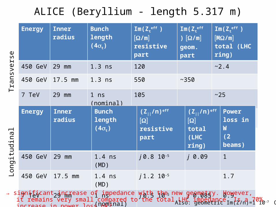
ALICE (Beryllium - length 5.317 m)Energy Inner radius Bunch length
(4st)Im(Zt
eff ) [W/m]
resistive partIm(Zt
eff )
[W/m] geom. part
Im(Zteff
) [MW/m] total (LHC ring)
450 GeV 29 mm 1.3 ns 120 ~2.4
450 GeV 17.5 mm 1.3 ns 550 ~350
7 TeV 29 mm 1 ns (nominal) 105 ~25
7 TeV 17.5 mm 1 ns (nominal) 480 ~350
Energy Inner radius Bunch length (4st)
(Z||/n)eff [ ]W
resistive part (Z||/n)eff
[ ]W total (LHC ring)
Power loss in W(2 beams)
450 GeV 29 mm 1.4 ns (MD) j 0.8 10-5 j 0.09 1
450 GeV 17.5 mm 1.4 ns (MD) j 1.2 10-5 1.7
7 TeV 29 mm 1 ns (nominal) j 0.5 10-5 j 0.085 0.9
7 TeV 17.5 mm 1 ns (nominal) j 0.8 10-5 1.6
Long
itudi
nal
Tran
sver
se
→ significant increase of impedance with the new geometry. However, it remains very small compared to the total LHC impedance. Is a 70% increase in power loss ok? Also: geometric Im(Z/n)=1 10-7 Ohm

Longitudinal impedance (broadband computed from ABCI, all materials PEC)
- No measurable difference in the real part of the impedance
- There is an increase of 7% of the imaginary part of the impedance

1 vs 2 layers
Difference visible below 100 kHz