implementation and performance evaluation of ieee 802.15.4
TRANSCRIPT
Implementation and PerformanceEvaluation of IEEE 802.15.4 Protocol
DAVID ANDREU
Master’s Degree ProjectStockholm, Sweden 2011
XR-EE-RT 2011:003

Implementation and Performance Evaluation ofIEEE 802.15.4 Protocol
DAVID ANDREU
Master’s ThesisSupervisor: Pangun Park
Examiner: Prof. Karl Henrik Johansson
XR-EE-RT 2011:003

iii
Abstract
In recent years, wireless sensor networks have attracted great interest ofboth academy and industry due to the wide range of contexts in which theycan be used. Considering the large number of applications and huge-scale de-ployments wireless sensor networks have been envisioned, standardization isa critical issue to guarantee the interoperability among platforms. The IEEE802.15.4 has become the most notable standard for wireless sensor networks andmany software and hardware platforms are based on it. The implementationand performance analysis of this standard is essential to understand the fun-damental limitations of it. Moreover, evaluation tools play an important roleto test new algorithms and other protocols based on this standard. Simulationis one the most valuable tools in protocol prototyping design and evaluation.Although there are many simulators available for wireless networks, many ofthem are not user-friendly programmable. On the other side, MATLAB be-comes very popular in different fields since it provides a powerful and easy touse environment. However, the number of wireless sensor network simulatorsbuilt on it is scarce.
In this thesis, a new simulator is developed using MATLAB for IEEE802.15.4 protocol which combines simplicity and accuracy. The performance ofthe simulator in terms of packet delivery rate and average delay is comparedwith an analytical model that considers all the key aspects of the standard. Thesimulator also provides a graphic user interface that allows the user to defineand draw network topologies. Moreover, the simulator includes a debuggingtool which permits to see graphically the 802.15.4 PHY and MAC events oc-curred during the simulation. This allows the user to analyze the underlyingcommunication among the nodes.
Furthermore, although some practical software implementations of IEEE802.15.4 protocol are available, there is no explicit comparison with their the-oretical bound of the network performance. TKN15.4 is the most advancedsoftware implementation. However, its validation through theoretical modelshas not been studied before. The performance of TKN15.4 is evaluated andcompared with the proposed analytical model. The impact of the known clockdrift is also analyzed for TKN15.4. Significant misalignments of the slot bound-aries and loss of beacon frames are observed, resulting in a certain gap withthe theory.

iv
Acknowledgments
First of all I would like to thank my supervisor Pangun Park for his constant guid-ance, attention and complete disposal at any moment, which made the work apleasant time.
Thanks to Aitor Hernandez, not only for his help during the initial stage of thework but also for being a good friend since the first time I met him.
I really appreciate the pleasant environment of the Automatic Control Groupas well as the time spent with the rest of the Master Thesis students during thebreaks.
It is difficult to mention all friends I have met in Sweden, from whom I have learnta lot of things and who made this period of my life an unforgettable experience.Thanks to all of them.
Finally, I would like to thank the people who have been always present, familyand friends in my homeland. A very special thank to my parents Miguel and Mariadel Carmen and my brother Miguel, for giving me any kind of support along theyears as well as my friends Albert, Antonio, Dani and Eric for the good momentstogether.
Contents
Contents v
Acronyms 1
1 Introduction 51.1 Motivation . . . . . . . . . . . . . . . . . . . . . . . . . . . . . . . . 61.2 Thesis outline . . . . . . . . . . . . . . . . . . . . . . . . . . . . . . . 7
2 Background 92.1 Challenges of WSN . . . . . . . . . . . . . . . . . . . . . . . . . . . . 92.2 Standardization . . . . . . . . . . . . . . . . . . . . . . . . . . . . . . 102.3 Platforms . . . . . . . . . . . . . . . . . . . . . . . . . . . . . . . . . 11
2.3.1 Hardware . . . . . . . . . . . . . . . . . . . . . . . . . . . . . 112.3.2 Software . . . . . . . . . . . . . . . . . . . . . . . . . . . . . . 132.3.3 Evaluation tools . . . . . . . . . . . . . . . . . . . . . . . . . 16
3 IEEE 802.15.4 protocol 213.1 General description . . . . . . . . . . . . . . . . . . . . . . . . . . . . 21
3.1.1 Introduction . . . . . . . . . . . . . . . . . . . . . . . . . . . 213.1.2 Components and topologies . . . . . . . . . . . . . . . . . . . 21
3.2 Physical layer specification . . . . . . . . . . . . . . . . . . . . . . . . 213.2.1 PPDU format . . . . . . . . . . . . . . . . . . . . . . . . . . . 233.2.2 Encoding specifications . . . . . . . . . . . . . . . . . . . . . 23
3.3 MAC sublayer specification . . . . . . . . . . . . . . . . . . . . . . . 253.3.1 Channel access . . . . . . . . . . . . . . . . . . . . . . . . . . 263.3.2 MPDU format . . . . . . . . . . . . . . . . . . . . . . . . . . 28
4 Analytical model for IEEE 802.15.4 MAC protocol 314.1 Background . . . . . . . . . . . . . . . . . . . . . . . . . . . . . . . . 314.2 System model . . . . . . . . . . . . . . . . . . . . . . . . . . . . . . . 314.3 Performance analysis . . . . . . . . . . . . . . . . . . . . . . . . . . . 32
5 Simulator development using MATLAB 355.1 Motivation . . . . . . . . . . . . . . . . . . . . . . . . . . . . . . . . 35
v
vi CONTENTS
5.2 Functional overview . . . . . . . . . . . . . . . . . . . . . . . . . . . 355.2.1 Physical and MAC layer models . . . . . . . . . . . . . . . . 355.2.2 Graphic user interface . . . . . . . . . . . . . . . . . . . . . . 375.2.3 Debugging tools . . . . . . . . . . . . . . . . . . . . . . . . . 37
5.3 Simulator architecture . . . . . . . . . . . . . . . . . . . . . . . . . . 375.4 Performance evaluation . . . . . . . . . . . . . . . . . . . . . . . . . 405.5 Summary . . . . . . . . . . . . . . . . . . . . . . . . . . . . . . . . . 43
6 Experimental evaluation of TKN15.4 456.1 Motivation . . . . . . . . . . . . . . . . . . . . . . . . . . . . . . . . 456.2 TKN15.4 overview . . . . . . . . . . . . . . . . . . . . . . . . . . . . 456.3 Performance evaluation . . . . . . . . . . . . . . . . . . . . . . . . . 47
6.3.1 Measurement procedure description . . . . . . . . . . . . . . 476.3.2 Experimental results . . . . . . . . . . . . . . . . . . . . . . . 51
6.4 Summary . . . . . . . . . . . . . . . . . . . . . . . . . . . . . . . . . 55
7 Conclusions and future work 577.1 Conclusions . . . . . . . . . . . . . . . . . . . . . . . . . . . . . . . . 577.2 Future work . . . . . . . . . . . . . . . . . . . . . . . . . . . . . . . . 57
Bibliography 59
Acronyms
ACK Acknowledgment frame 15, 16, 28, 31, 33, 34, 37, 39, 40, 42, 43, 47–49, 52
ADC Analog to Digital Converter 11
AES Advanced Encryption Standard 10
ASK Amplitude Shift Keying 22
BAN Body Area Network 17
BER Bit Error Rate 36
BPSK Binary Phase Shift Keying 22
CAP Contention Access Period 26–28, 32–34, 45, 46, 51, 53
CCA Clear Channel Assessment 22, 27, 28, 34, 36, 37, 39, 40, 43
CFP Contention Free Period 26, 31, 32, 46
CSMA-CA Carrier Sense Multiple Access with Collision Avoidance 10, 15, 16, 22,26–28, 31–33, 37, 39, 48, 49, 54, 57, 58
DAC Digital Analog Converter 11
DARPA Defense Advanced Research Projects Agency 5, 13
DMA Direct Memory Access 11
DSSS Direct-Sequence Spread Spectrum 10, 22
FCC Federal Communications Commission 11
FCF Frame Control Field 28, 30
FCS Frame Check Sequence 28, 30
FFD Full-Function Device 21
1
2 ACRONYMS
GTS Guaranteed Time Slots 15, 26, 28, 33, 45
GUI Graphic User Interface 18, 35, 37, 57
IEEE Institute of Electrical and Electronics Engineers 10
IETF Internet Engineering Task Force 10, 11, 14
IFS Interframe Spacing 28
IP Internet Protocol 11
ISM Industrial, Scientific and Medical 10
LIFS Long Interframe Spacing 28
LQI Link Quality Indicator 22
LSB Least Significant Bit 24
MAC Medium Access Control 6, 7, 9, 10, 18, 23, 25–28, 30–32, 34, 35, 37, 39, 40,42, 45–47, 51, 57
MFR MAC Footer 30
MHR MAC Header 28
MPDU MAC Protocol Data Unit 30
MSB Most Significant Bit 24
O-QPSK Offset Quadrature Phase Shift Keying 22, 24
PAN Personal Area Network 15, 21, 26, 27
PDR Packet Delivery Rate 34, 40, 42, 43, 45, 47–49, 51–55, 57
PHR PHY Header 23
PHY Physical layer 10, 21–23, 27, 28, 35, 37, 39, 40, 57
PN Pseudo-random Noise 24
PPDU PHY Protocol Data Unit 23, 24
PSDU PHY Service Data Unit 24, 30
PSSS Parallel Sequence Spread Spectrum 22
QoS Quality of Service 9
ACRONYMS 3
RAM Random-Access Memory 11
RFD Reduced-Function Device 21
RoHS Restriction of Hazardous Substances 11
SFD Start-of-Frame Delimiter 23
SHR Synchronization Header 23
SIFS Short Interframe Spacing 28
SINR Signal to Interference-plus-Noise Ratio 36, 40
SMA SubMiniature version A 11
SNR Signal to Noise Ratio 36
TDMA Time Division Multiple Access 10
USB Universal Serial Bus 11
WPAN Wireless Personal Area Network 6, 10
WSN Wireless Sensor Network 5–7, 9, 10, 13, 14, 16–19, 31, 35, 54, 57, 58

Chapter 1Introduction
Wireless Sensor Networks (WSNs) have been an active research area in telecom-munication for around a decade. Initial research on WSN grew out of initiativesfocused on general mesh networks. The development of these networks was mainlymotivated by military applications such as battlefield surveillance. Many majorinitiatives in the field, such as the TinyOS community [1], grew out of DARPA(Defense Advanced Research Projects Agency) [2], reflecting an initial source ofresearch founding from military field.
A WSN is a built of spatially scattered and autonomous nodes, from a few ofthem to several thousands, where each node is connected to one or more sensorsfor monitoring environmental conditions, such as temperature, pressure or motion,and to cooperatively pass their data through the network to a main location. Eachsensor node of the network is an electronic device which normally consists on aradio transceiver with an internal antenna or a connection to an external antenna, amicrocontroller, a circuit for communicating with the sensors and an energy source,typically a battery. Due to the wireless nature of these networks and the fullyenvisioned self-contained characteristic of the nodes, WSNs are suitable in numerouscontexts, even in hazardous ones, covering a large range of applications in bothmilitary and civilian areas.
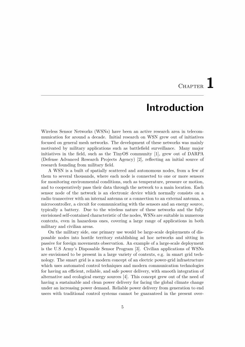
On the military side, one primary use would be large-scale deployments of dis-posable nodes into hostile territory establishing ad hoc networks and sitting inpassive for foreign movements observation. An example of a large-scale deploymentis the U.S Army’s Disposable Sensor Program [3]. Civilian applications of WSNsare envisioned to be present in a large variety of contexts, e.g. in smart grid tech-nology. The smart grid is a modern concept of an electric power-grid infrastructurewhich uses automated control techniques and modern communication technologiesfor having an efficient, reliable, and safe power delivery, with smooth integration ofalternative and ecological energy sources [4]. This concept grew out of the need ofhaving a sustainable and clean power delivery for facing the global climate changeunder an increasing power demand. Reliable power delivery from generation to endusers with traditional control systems cannot be guaranteed in the present over-
5
6 CHAPTER 1. INTRODUCTION
Figure 1.1: Smart grid network (U.S. department of energy,http://www.oe.energy.gov/).
stressed, overaged and fragile electricity infrastructure. Instead of the conventionalcommunication technologies, the collaborative and low-cost nature of WSNs bringsimportant advantages in the monitoring, diagnostics and protection of the powernetwork. Figure 1.1 shows an example of the structure of a smart-grid network.The use of wireless technology in monitoring and process control can be extendedto many industrial activities with the consequent benefits of flexibility for locatingand maintaining the sensors unlike the traditional wired networks. For example,Emerson Process Management and BP have collaborated together to improve theperformance of factory automation by using wireless technology. Emerson’s wirelessinstallation on BP refinery’s coke calciner controls the temperatures preventing fanand conveyor failure [5].
WSNs are also suitable for precision agriculture, for example, in environmentswith low water resources. Water reduction can be attained by providing water ona per-need basis. More applications of WSNs can be found in [3].
1.1 Motivation
The great number of applications in which WSNs could be present, has involvedthe academy, industry and standardization bodies to make these networks a reality.Within the different standardization bodies, above all, IEEE is the most notable inthe area with the standard IEEE 802.15.4, which specifies the physical and MAClayers for low-rate Wireless Personal Area Networks (WPANs). Other overlay spec-
1.2. THESIS OUTLINE 7
ifications are based on it as well as many hardware and software platforms andevaluation tools. Within the latter ones, many simulators, emulators and testbedsare available to assist the development and test of new protocols and algorithms.Simulation is one of the most valuable evaluation tools since it is a simple and ef-ficient way for prototype design. Simulators are available in the form of generalpurpose network simulators or specific wireless sensor network simulators. Withinthem, it can be found different levels of accuracy, extensibility, reusability and scal-ability (capacity of running simulations of networks with several nodes). However,a common problem these simulators present is that they are hard to use in practiceand not as easy-programming as other environments offer like MATLAB [6]. Thedevelopment environment that MATLAB provides has not been exploited and onlya few WSN simulators are based on it. In this thesis, a new simulator based on theIEEE 802.15.4 standard is developed for MATLAB. The main aim of the simulatoris to offer an environment easy to use and extend as well as provide reliable resultscontrasted with theoretical results. The analytical model detailed in [7], which isthe most accurate for the IEEE 802.15.4 MAC since it models all of its key factors,is used for the evaluation of the performance results of the simulator.
This analytical model is also used in this thesis for the evaluation of one ofthe most outstanding and complete software implementation of the standard, theTKN15.4. In contrast with other implementations, no significant bugs that mayalter the proper operation have been reported for TKN15.4. However, its validationthrough comparison with theoretical models is necessary and is one of the goals ofthis thesis.
1.2 Thesis outlineIn Chapter 2 we give an overview of the WSNs, which includes their general require-ments, standardization status and software and hardware platforms. In Chapter 3the specifications and functionalities defined in the IEEE 802.15.4 standard aredescribed. In Chapter 4 is presented the analytical model used in this thesis forcontrasting the performance results of the developed simulator as well as of theTKN15.4 implementation. Chapter 5 presents the characteristics of the simula-tor and its evaluation. In Chapter 6 the TKN15.4 is evaluated through extensiveexperiments. Finally, we conclude and discuss the future work in Chapter 7.

Chapter 2Background
In Section 2.1 some characteristics of the WSNs are presented as well as their mainrequirements taking into account the large number of different applications. InSection 2.2 the main efforts are summarized in terms of standards and specificationsto make WSNs a reality. Finally, a survey of platforms of hardware, software andevaluation tools shows the state of the art in WSN area as well as some of the toolsused in this thesis.
2.1 Challenges of WSN
Nowadays the major problem in deploying WSN is their limited battery power. Themain design criterion is to extend the lifetime of the network without compromisingreliable and efficient communications. For this reason, the optimization is essentialstep to design communication protocols. The MAC is a key component, since itcontrols the active and sleeping state of each node coordinating them to access toa common medium. Considering the large variety of applications where WSNs areenvisioned to be used, protocol design needs to trade the following challenges:
• Reliability: Sensor readings must be exchanged amongst nodes and networksink with a given probability of success. In many scenarios the loss of sensorinformation could be critical. Reliability can be maximized but it may increasethe network energy consumption. Hence, a tradeoff is necessary.
• Delay: Sensor readings must be received by the network sink within somedeadline. Delay is one of the main Quality of Service (QoS) measurements,specially in industrial control applications, where outdated packets are gener-ally not useful.
• Energy efficiency: For affordable WSN deployments, energy-efficient oper-ations are mandatory. The limited energy budget of a sensor node togetherwith the requirement of long network lifetime is the strict design constraint.
9
10 CHAPTER 2. BACKGROUND
• Scalability and adaption: Protocol should be able to adapt to variation inthe network size and topology as well as variations in the wireless channel orapplication requirements.
Protocol design shall take into account the previous requirements but also considerpractical implementations due to the limited computational resources of a wirelesssensor node. Many protocol communication standards and specifications are cur-rently either under development or ratified. A survey of standards and specificationsefforts for WSNs is discussed in the following section.
2.2 StandardizationThe major standardization bodies in the WSN area are the Institute of Electricaland Electronics Engineers (IEEE), the Internet Engineering Task Force (IETF) andthe HART communication foundation. Notable standards and specifications are:
• IEEE 802.15.4 standard [8] specifies the PHY and MAC layer for low-rateWPANs. Many platforms are based on this standard and other specifications,such as Zigbee and wirelessHART specifications, are built on top of the stan-dard covering the upper layers to provide a complete networking solution.Some of the main characteristics of the IEEE 802.15.4 are:
– 250 kbps, 40 kbps and 20 kbps data rates.– Two addressing modes, 16-bit short and 64-bit IEEE addressing.– CSMA-CA channel access.– Automatic network establishment by the coordinator of the network.– Power management control.– 16 channels in the 2.4 GHz ISM band, 10 channels in the 915 MHz ISM
band and one channel in the 868 MHz band.
IEEE 802.15.4 PHY and MAC layers are described in the next chapter.
• Zigbee is a specification for a suite of high level communication protocolsbased on the IEEE 802.15.4 physical and MAC layers. The specification isdeveloped by a consortium of industry players, the Zigbee Alliance. Some ofthe commercial applications of WSNs using Zigbee are in the area of homeand building automation, remote control or health care monitoring [2].
• WirelessHART is an open-standard wireless mesh network communicationprotocol designed to meet the needs for process automation applications. Ituses IEEE 802.15.4 compatible DSSS radios and operates in the 2.4 GHz ISMband. On the MAC layer, the protocol uses the Time Division Multiple Access(TDMA) technology. It provides highly secure communications by using AES-128 block ciphers and symmetric keys. WirelessHART is backward compatible
2.3. PLATFORMS 11
with existing HART devices and applications. The other outstanding featuresinclude reliability and scalability [9].
• 6LoWPAN is the abbreviation of IPv6 over Low power Wireless PersonalArea Networks. 6lowpan is the name of a working group of the IETF. Thegroup has defined encapsulation and header compression mechanisms thatallow IPv6 packets to be sent to and received from over IEEE 802.15.4 basednetworks. The base specification can be found in [10].
2.3 Platforms
2.3.1 HardwareMotes
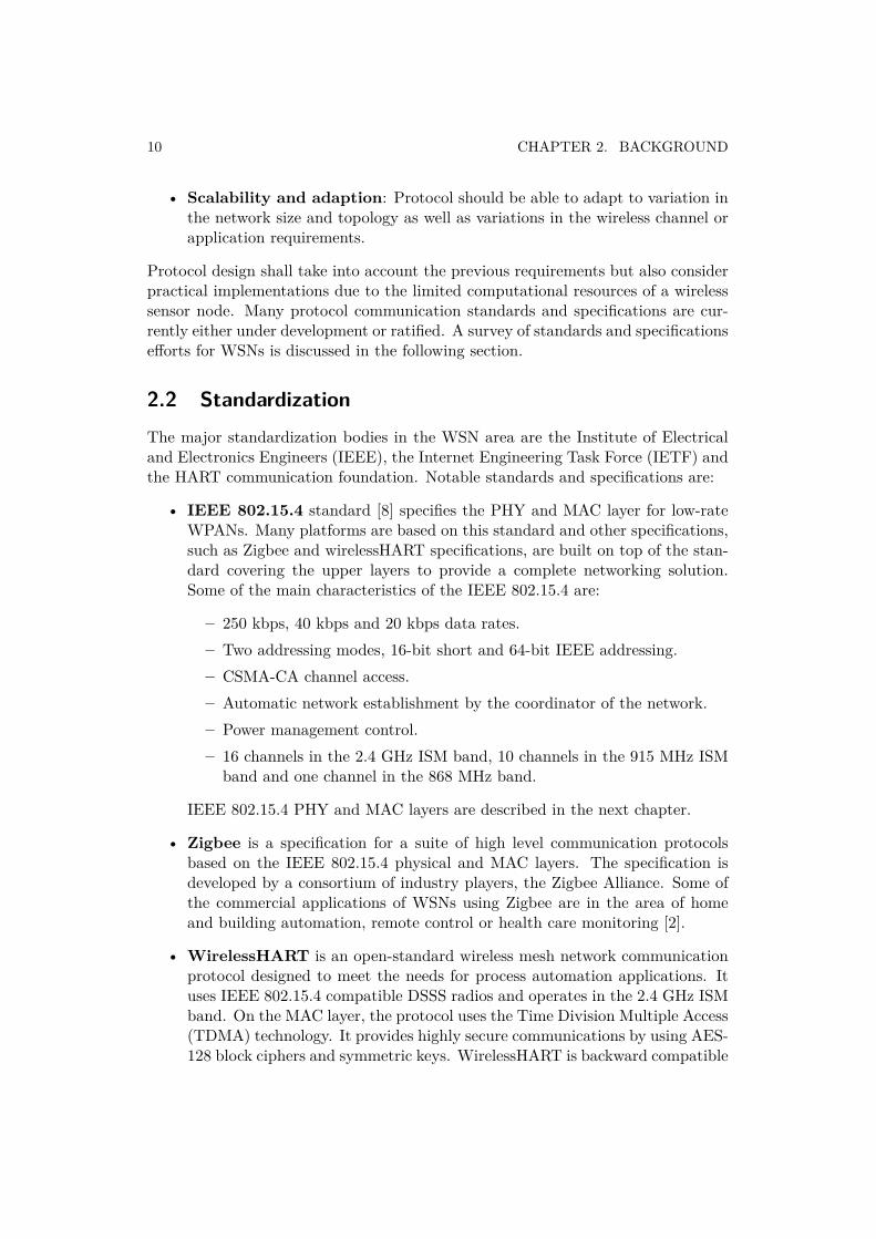
Wireless sensor devices are also colloquially known as motes. Some of the mostcommon used motes are Tmote Sky, Telosb, MicaZ and iMote2. In this thesis,Tmote Sky [11] motes have been used for the experimental evaluation of TKN15.4implementation. Tmote Sky are ultra low power wireless devices. Based on industrystandards, Tmote Sky enables a wide range of mesh network applications since itintegrates sensors of light, temperature and humidity and provides interconnectionwith peripherals. Tmote Sky leverages emerging wireless protocols, such as theIEEE 802.15.4. Some of its key features are:
• 250kbps 2.4GHz IEEE 802.15.4 Chipcon wireless transceiver
• Interoperability with other IEEE 802.15.4 devices
• 8MHz Texas Instruments MSP430 microcontroller (10k RAM, 48k Flash)
• Integrated ADC, DAC, Supply Voltage Supervisor, and DMA Controller
• Integrated onboard antenna with 50m range indoors / 125m range outdoors
• Integrated Humidity, Temperature, and Light sensors
• Ultra low current consumption
• Fast wakeup from sleep (<6µs)
• Hardware link-layer encryption and authentication
• Programming and data collection via USB
• 16-pin expansion support and optional SMA antenna connector
• TinyOS support : mesh networking and communication implementation
• Complies with FCC Part 15 and Industry Canada regulations
• Environmentally friendly complies with RoHS regulations
12 CHAPTER 2. BACKGROUND
Figure 2.1: Tmote Sky without battery extension.
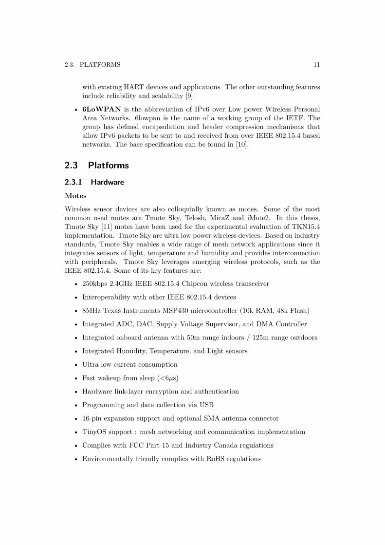
Figure 2.2: CC2420DK development kit.
Protocol analyzer
In order to analyze the frames transmitted by the motes in the experimental evalua-tion of the TKN15.4, a promiscuous device has been used as a sniffer. Such device isthe CC2420DK development kit [12] running together with the SmartRFT M PacketSniffer software from Texas Instruments. The development kit includes a CC2400EBEvaluation Board and a CC2420EM Evaluation Module. The Evaluation Modulecontains the CC2420 radio chip [13]. The Evaluation Board serves as a mother-board for the Evaluation Module providing different connectors to make it easy tointerface with Texas Instruments software and various test equipment. Although ithas been used at first time for analyzing the transmitted frames, the developmentkit present some relevant limitations when evaluating the performance of TKN15.4,
2.3. PLATFORMS 13
e.g. overflow problems for high traffic conditions or not capturing all transmittedframes.
2.3.2 Software
Operating Systems
Operating systems for WSN nodes are not as complex as general-purpose operatingsystems since they are deployed for some particular applications, rather than ageneral platform. Examples of operating systems are TinyOS [1], Contiki [14],LiteOS [15] and Nano-RK [16].
• TinyOSTinyOS is a free and open source component-based operating system designedfor low-power wireless devices. It started as a project of the DARPA NESTprogram, developed at the University of California, Berkeley, and has grownto become an international consortium, the TinyOS Alliance. A worldwidecommunity from academia and industry use, develop, and support the TinyOSoperating system as well as its associated tools.TinyOS is based on an event-driven programming model, where programs arecomposed into event handlers and tasks. TinyOS signals the correspondingevent handler when an external event occurs, such as a sensor reading oran incoming data packet. Event handlers can post tasks that are scheduledby the TinyOS kernel some time later. It is highly modular, allowing thecustomization and adaption of it to several hardware platforms. It is writtenin nesC (Network Embedded Systems C) [17], an extension of C designed toembody the structuring concepts and execution model of TinyOS. Some of itsbasic characteristics are:
– Structured in components: Programs are built out of components,which are linked ("wired") to form whole programs. Components haveinternal concurrency in the form of tasks. Threads of control may passinto a component through its interfaces. These threads are rooted eitherin a task or a hardware interrupt.
– Specification of component behavior through interfaces: Inter-faces may be provided or used by components. The provided interfacesare intended to represent the functionality that the component providesto its user, and the used interfaces represent the functionality the compo-nent needs to perform its job. The interfaces are bidirectional, specifyinga set of functions to be implemented by the interface’s provider (com-mands) and a set to be implemented by the interface’s user (events).This allows a single interface to represent a complex interaction betweencomponents (e.g., registration of interest in some event, followed by acallback when that event happens).
14 CHAPTER 2. BACKGROUND
– Components are statically linked: By the static specification of thecomponents interfaces, the runtime efficiency is increased.
• ContikiContiki is an open source, highly portable, multi-tasking and memory-efficientoperating system for networked embedded systems and WSNs. Contiki hasbeen used in different kinds of projects, such as road tunnel fire monitoring,water monitoring in the Baltic Sea, and in surveillance applications. It isdesigned for microcontrollers with low memory, typically about 2 kilobytes ofRAM and 40 kilobytes of ROM. Some of its main features are:
– Power-efficiency: Contiki provides a software-based power profilingmechanism which tracks the energy expenditure of each sensor node with-out the need of additional hardware. This mechanism can be used forboth as a research tool for experimental evaluation of sensor networkprotocols, and as a way to estimate the lifetime of a network.
– Programming model and software development: Contiki is writ-ten in the C programming language and consists of an event-driven ker-nel, on top of which application programs can be dynamically loadedand unloaded at run time. For user convenience, Instant Contiki allowsa single-file download that contains all necessary tools and compilers fordeveloping software for Contiki operating system.
– On-node Storage: Coffee is a flash-based file system provided by Con-tiki which allows storing data inside the sensor network.
– Simulators: Contiki provides three simulation environments, MSPsimemulator, Cooja cross-layer network simulator, and the netsim process-level simulator, to assist the software development for this platform be-fore the code is loaded on the target hardware.
– Network interaction: Contiki provides interaction with networks basedon this operating system through a Web browser application, a Unixcommand shell-based interface, or a dedicated software for displayinggraphically stored data.
IEEE 802.15.4 implementation
As shown in Section 2.2, IEEE 802.15.4 standard has attracted strong interest inboth academia and industry and has been adopted by many other WSNs stan-dards, such as Zigbee, WirelessHART and IETF 6lowPAN. Here, an overview oftwo open-source IEEE 802.15.4 implementation is presented: OpenZB-IPP Hur-ray and TKN15.4. Both implementations are based on TinyOS, which is the mostextended operating system in the WSN community.
• OpenZB-IPP Hurray
2.3. PLATFORMS 15
OpenZB-IPP Hurray is an implementation of the standard in nesC/TinyOSfor the MicaZ and TelosB motes. It is developed and supported by CISTER(Research Centre in Real-Time Computing Systems), a Research Unit at theSchool of Engineering (ISEP) of the Polytechnic Institute of Porto (IPP),Portugal. IPP-Hurray research group is the core of the CISTER. The im-plementation is provided as a toolset to implement, test and evaluate thefunctionalities defined in the standard as well as to enable the development offunctionalities not yet implemented. According to the technical report of theversion 1.2 of the implementation, the implemented 802.15.4 functionalitiesare(see [8] for detailed description of the IEEE 802.15.4 functionalities):
– CSMA-CA algorithm - Slotted version– GTS Mechanism– Indirect transmission mechanism– Direct / Indirect / GTS Data Transmission– Beacon Management– Frame construction - Short Addressing Fields only and extended address-
ing fields in the association request– Association/Disassociation Mechanism– MAC PIB Management– Frame Reception Conditions– Energy Detection and PASSIVE channel scan
On the other hand, the missing functionalities are:
– Unslotted version CSMA-CA. Implemented but not fully tested– Extended Address Fields of the Frames– IntraPersonal Area Network (PAN) Address Fields of the Frames– Active and Orphan channel Scan– Orphan Devices– Security services
In addition to the missing functionalities, there are important known issuesin the OpenZB-IPP Hurray implementation. An example of such issues arethe low accuracy in the synchronization mechanism with a significant gapbetween the time of beacon is being transmitted and its expected value. Hence,the interoperability within different platforms cannot be guaranteed. Otherproblems are related to the ACK mechanism or motes stop working aftersome time. These issues have been reported in [18]. Hence, OpenZB-IPPHurray may not be considered as a complete and fully validated IEEE 802.15.4protocol implementation.
16 CHAPTER 2. BACKGROUND
• TKN15.4As OpenZB-IPP Hurray, TKN15.4 implementation is also written in nesC/TinyOS. TKN15.4 is developed by the Technical University Berlin - Telecom-munication. The associated technical report of the first release can be found in[19]. One of the TKN15.4 primary design goals is to be platform-independent.Once a proper radio chip driver is met as well as timers that satisfy the ac-curacy and precision requirements of the standard, the MAC implementationcan be used on any TinyOS platform. The missing functionalities in the im-plementation are:
– Indirect transmissions. Frames are not kept in transaction queue incase CSMA-CA algorithm fails.
– Transmissions modes. On beacon-enabled mode, if the device can-not track the beacon, the frame is not transmitted, but according IEEE802.15.4 standard, the device should send the frame using the unslottedversion of the CSMA-CA algorithm. In TKN15.4, one component asso-ciated to the slotted CSMA-CA mode or unslotted CSMA-CA is chosenat compile time. Hence, the total space used in ROM is reduced but itis not possible to switch from one mode to another in run time.
– Frame pending. Frame pending flags are (need to be) always set in theACK headers.
In addition to the missing functionalities, a complete evaluation and validationof this implementation by comparing with analytical results is still remainingand is one of the scopes of this thesis. An experimental TKN15.4 performanceevaluation can be found in Chapter 6.
2.3.3 Evaluation tools
Designers of the WSN community need to evaluate their algorithms and proto-cols. Real experiments may not be feasible or practical to test and evaluate sinceit may involve placement of thousands of nodes in harsh or inaccessible terrains.Analytical modeling methods require some simplifications to model and predict theperformance. Therefore, they are inappropriate in many scenarios due to inherentcomplexity of WSNs. Thus, simulators, emulators and testbeds are invaluable toolsfor an effective evaluation of algorithms and protocols at design, development andimplementation stages. In this section, a survey of the main evaluation tools ispresented.
Simulation tools
Simulation is the most extended, effective and feasible approach to design, developand evaluate network protocols and algorithms. Simulators model and predict thebehavior of real environment in different scenarios but generally, the models adopted
2.3. PLATFORMS 17
by simulators may not be accurate. They offer important advantages such as lowercost, scalability, time and ease of implementation. There are different simulators,which can be general purpose simulators, such as ns-2 [20], OMNET++ [21] andOPNET [22] and specifically designed for simulation of WSNs. Some of the WSNspecific simulators are:
• SensorSim [23]: It is the first wireless sensor simulator but it is not supportedanymore. It is built on ns-2 and includes important extensions of it. One ofthem is the accurate power consumption model it provides. Moreover, it hasa more complex model of phenomena events sensing than ns-2. However,it is still simplistic. It also provides support for interaction with externalapplications in order to trigger real events sensed by real sensor nodes. On theother side, one of its main drawbacks is the low scalability it offers, since it isbased on ns-2, an object oriented simulator in which each node is representedas an object whose dependencies must be checked each simulation intervalresulting in a high computational cost for networks formed by several nodes.
• Castalia [24]: Built on OMNET++, it allows to test algorithms and networkprotocols in WSNs, Body Area Networks (BANs), and networks of low-powerembedded devices. Its main feature is the advanced wireless channel and radiomodels. Other features are the implementation of MAC and routing protocols,such as some functionalities of the IEEE 802.15.4, sensing model and CPUpower consumption.
• Prowler [25] /JProwler [26]: Built on MATLAB, it is designed to simulateMica motes running TinyOS in addition to generic wireless networks, and itis a good tool for protocol and algorithm development. It provides hybridsimulation, i.e. deterministic (application testing) and probabilistic (wirelesscommunication channel and low-level node protocol simulation) modes. It cansimulate transmission, propagations and reception including collisions in adhoc networks. IEEE 802.15.4 functionalities are not implemented. JProwleris based on java and provides the same capabilities than Prowler.
• TrueTime [27]: It is a MATLAB/SIMULINK-based simulator for real-timecontrol systems. It facilitates co-simulation of controller task execution in real-time kernels and networks transmissions. It implements some IEEE 802.15.4beacon-enabled mode functionalities but they have not been compared withtheoretical models. Although there are some ad hoc networking examplesmade at application code, TrueTime does not support routing protocols. Asit is based on MATLAB/SIMULINK, the threshold for a non-SIMULINK userto start using/extending it is high. SIMULINK is a relatively new MATLABextension for dynamic systems simulations that provides a graphical environ-ment where the systems definition are based on a block modular design.
• Sidh [28]: It is a specific wireless sensor network simulator written in java. Itallows a high level of customization for having realistic and accurate simula-
18 CHAPTER 2. BACKGROUND
tions. However is relatively inefficient. Furthermore, there are a few protocolsalready implemented in its original code.
Emulation tools
Emulation is a combination of hardware and software approach in which some com-ponents are implemented on real platform (e.g. run code in real motes) and otherare simulated (e.g. channel links). Some emulators for WSNs are:
• TOSSIM [29]: It is designed to simulate TinyOS applications based on Micaplatforms. Instead of compiling a TinyOS application for a mote, users com-pile it for TOSSIM framework, which runs on a PC, allowing to test and debuguser code as well as analyze algorithms in a controlled and repeatable environ-ment. One of its main features is the high level of scalability it offers which isachieved by using the same code for all the nodes, i.e. all nodes are identical,where each of these nodes are connected in a direct graph by edges with agiven probabilistic bit error. This model permits to handle larger networksthan any other simulators or emulators, but it results in many inaccuraciesand low effectiveness when analyzing low level protocols. Moreover, it doesnot support gathering power measurement.
• ATEMU [30]: It is also compatible with Mica motes like TOSSIM, but it in-troduces further improvements. It uses an XML configuration file to configurethe network in a hierarchical manner (characteristics of the network definedat top level and characteristics of each node defined at lower levels), and pro-vides a graphic user interface (GUI) to debug and monitor code execution. Ithas a more accurate emulation model than TOSSIM. On the other side, thehigh level of accuracy is achieved by sacrificing significantly the speed and thescalability.
• Avrora [31]: It allows simulation experiments with networks of up to 10.000nodes and performs as much as 20 times faster than previous emulators withsame accuracy. Unlike TOSSIM and ATEMU, Avrora is based on java andsimulates each node as its own thread while still running Mica code.
• SENSE [32]: It is a component-based software environment designed forbeing extended, reusable and scalable. Autonomous nature of componentsallows several capabilities such as the use of different battery models, network,MAC and physical layer functionalities.
• COOJA [33]: It is a cross-level framework for Contiki operating system, i.e.it combines simulation of high-level layers with low-level hardware behavioremulation by providing three levels of abstraction: networking (or applica-tion) level, operating system level and the machine code instruction set level.Although it is possible theoretically to run TinyOS applications in Cooja, it
2.3. PLATFORMS 19
failed when testing the example applications included in TKN15.4 and theobserved emulated network behavior was not as expected.
Testbed tools
Testbeds strive to bridge the gap between simulation and real deployment providingmore accurate results than the oversimplified models that simulators/emulatorsimplement. It provides an environment for protocol testing and evaluation similarto real deployment giving the opportunity to remotely configure, run and monitorexperiments. Some of the physical testbeds environments are:
• MoteLab [34]: It offers a public testbed for development and testing of sen-sor network applications via an intuitive web-based interface. It deploys 190TMote Sky sensor nodes running with TinyOS. The project goal is to facil-itate research in sensor network programming environments, communicationprotocols, and applications in a physical experimentation scenario.
• SensorScope [35]: It is a large-scale of distributed solar-powered stationswhich communicate wirelessly, constituting a WSN. The stations sense keyenvironmental data such as temperature, humidity or wind speed and direc-tion, allowing environmental scientists to use a comprehensive portal to survey,analyze and control the measurement process through a web-based interface.
• Emulab [36]: It is a network testbed publically available with any charge. Itoffers integrated access to a wide range of environments to develop, debug, andevaluate network systems. Some of these environments are: Emulation, Live-Internet, Experimentation, 802.11 Wireless, Software-Defined Radio, SensorNetworks, and Simulation.
More simulation, emulation and testbed evaluation tools can be found in [37].

Chapter 3IEEE 802.15.4 protocol
3.1 General description
3.1.1 Introduction
The standard describes the physical and MAC sublayers for low cost and self-organizing networks with very low power consumption. It is designed for appli-cations with relaxed throughput requirements. As mentioned before, it serves asthe basis of other significant specifications, such as Zigbee and wirelessHART.
In this chapter it is presented an overview of the standard, giving more attentionto the MAC functional description.
3.1.2 Components and topologies
The basic component is the device, which can be a Full-Function Device (FFD) or aReduced-Function Device (RFD). FFDs can talk with both RFDs and FFDs whileRFDs can only talk with FFDs.
The FFD can operate in three modes: PAN coordinator, coordinator or device.A network shall include at least one FFD, operating as the PAN coordinator.
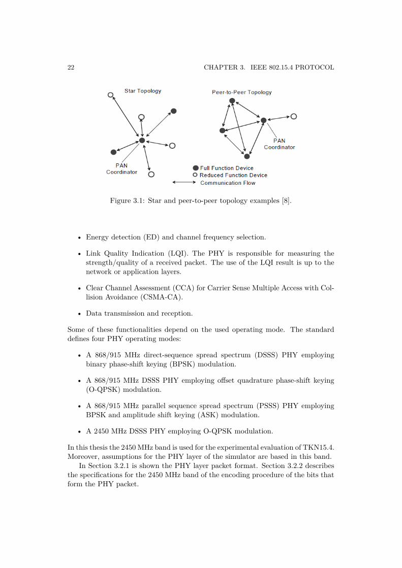
IEEE 802.15.4 can operate in two different topologies depending on the applica-tion requirements: the star topology or the peer-to-peer topology. Both are shownin Figure 3.1. In the star topology the communication is established between de-vices and the PAN coordinator, which is the central controller. The peer-to-peertopology also has a PAN coordinator but in this case any device may communicatewith any other device as long as they are in range of one another.
3.2 Physical layer specification
The PHY layer of the IEEE 802.15.4 is responsible for:
• Activation and deactivation of the radio transceiver.
21
22 CHAPTER 3. IEEE 802.15.4 PROTOCOL
Figure 3.1: Star and peer-to-peer topology examples [8].
• Energy detection (ED) and channel frequency selection.
• Link Quality Indication (LQI). The PHY is responsible for measuring thestrength/quality of a received packet. The use of the LQI result is up to thenetwork or application layers.
• Clear Channel Assessment (CCA) for Carrier Sense Multiple Access with Col-lision Avoidance (CSMA-CA).
• Data transmission and reception.
Some of these functionalities depend on the used operating mode. The standarddefines four PHY operating modes:
• A 868/915 MHz direct-sequence spread spectrum (DSSS) PHY employingbinary phase-shift keying (BPSK) modulation.
• A 868/915 MHz DSSS PHY employing offset quadrature phase-shift keying(O-QPSK) modulation.
• A 868/915 MHz parallel sequence spread spectrum (PSSS) PHY employingBPSK and amplitude shift keying (ASK) modulation.
• A 2450 MHz DSSS PHY employing O-QPSK modulation.
In this thesis the 2450 MHz band is used for the experimental evaluation of TKN15.4.Moreover, assumptions for the PHY layer of the simulator are based in this band.
In Section 3.2.1 is shown the PHY layer packet format. Section 3.2.2 describesthe specifications for the 2450 MHz band of the encoding procedure of the bits thatform the PHY packet.
3.2. PHYSICAL LAYER SPECIFICATION 23
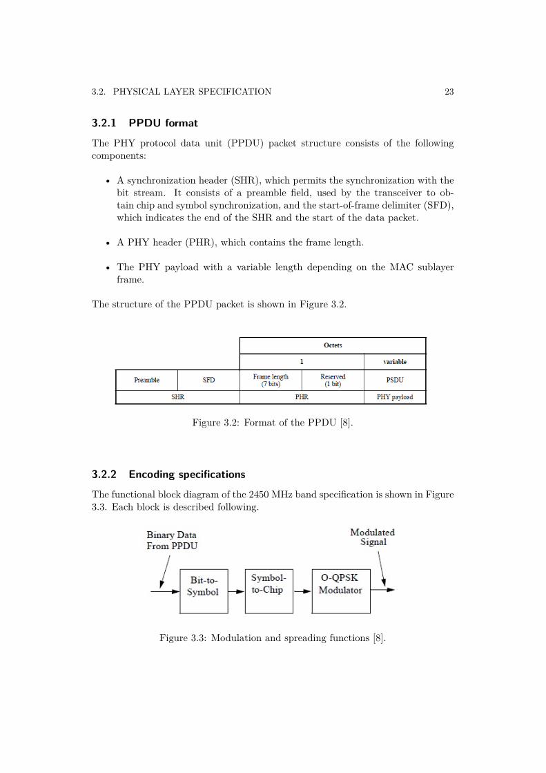
3.2.1 PPDU format
The PHY protocol data unit (PPDU) packet structure consists of the followingcomponents:
• A synchronization header (SHR), which permits the synchronization with thebit stream. It consists of a preamble field, used by the transceiver to ob-tain chip and symbol synchronization, and the start-of-frame delimiter (SFD),which indicates the end of the SHR and the start of the data packet.
• A PHY header (PHR), which contains the frame length.
• The PHY payload with a variable length depending on the MAC sublayerframe.
The structure of the PPDU packet is shown in Figure 3.2.
Figure 3.2: Format of the PPDU [8].
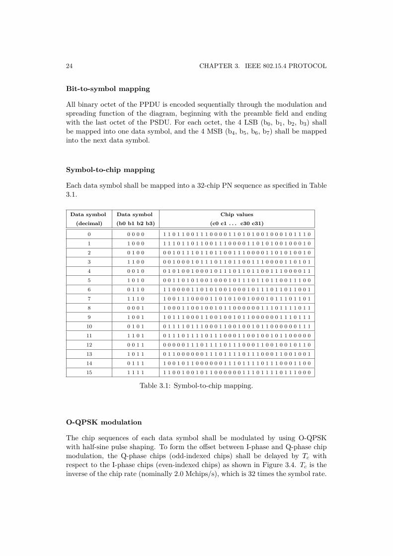
3.2.2 Encoding specifications
The functional block diagram of the 2450 MHz band specification is shown in Figure3.3. Each block is described following.
Figure 3.3: Modulation and spreading functions [8].
24 CHAPTER 3. IEEE 802.15.4 PROTOCOL
Bit-to-symbol mapping
All binary octet of the PPDU is encoded sequentially through the modulation andspreading function of the diagram, beginning with the preamble field and endingwith the last octet of the PSDU. For each octet, the 4 LSB (b0, b1, b2, b3) shallbe mapped into one data symbol, and the 4 MSB (b4, b5, b6, b7) shall be mappedinto the next data symbol.
Symbol-to-chip mapping
Each data symbol shall be mapped into a 32-chip PN sequence as specified in Table3.1.
Data symbol Data symbol Chip values(decimal) (b0 b1 b2 b3) (c0 c1 . . . c30 c31)
0 0 0 0 0 1 1 0 1 1 0 0 1 1 1 0 0 0 0 1 1 0 1 0 1 0 0 1 0 0 0 1 0 1 1 1 0
1 1 0 0 0 1 1 1 0 1 1 0 1 1 0 0 1 1 1 0 0 0 0 1 1 0 1 0 1 0 0 1 0 0 0 1 0
2 0 1 0 0 0 0 1 0 1 1 1 0 1 1 0 1 1 0 0 1 1 1 0 0 0 0 1 1 0 1 0 1 0 0 1 0
3 1 1 0 0 0 0 1 0 0 0 1 0 1 1 1 0 1 1 0 1 1 0 0 1 1 1 0 0 0 0 1 1 0 1 0 1
4 0 0 1 0 0 1 0 1 0 0 1 0 0 0 1 0 1 1 1 0 1 1 0 1 1 0 0 1 1 1 0 0 0 0 1 1
5 1 0 1 0 0 0 1 1 0 1 0 1 0 0 1 0 0 0 1 0 1 1 1 0 1 1 0 1 1 0 0 1 1 1 0 0
6 0 1 1 0 1 1 0 0 0 0 1 1 0 1 0 1 0 0 1 0 0 0 1 0 1 1 1 0 1 1 0 1 1 0 0 1
7 1 1 1 0 1 0 0 1 1 1 0 0 0 0 1 1 0 1 0 1 0 0 1 0 0 0 1 0 1 1 1 0 1 1 0 1
8 0 0 0 1 1 0 0 0 1 1 0 0 1 0 0 1 0 1 1 0 0 0 0 0 0 1 1 1 0 1 1 1 1 0 1 1
9 1 0 0 1 1 0 1 1 1 0 0 0 1 1 0 0 1 0 0 1 0 1 1 0 0 0 0 0 0 1 1 1 0 1 1 1
10 0 1 0 1 0 1 1 1 1 0 1 1 1 0 0 0 1 1 0 0 1 0 0 1 0 1 1 0 0 0 0 0 0 1 1 1
11 1 1 0 1 0 1 1 1 0 1 1 1 1 0 1 1 1 0 0 0 1 1 0 0 1 0 0 1 0 1 1 0 0 0 0 0
12 0 0 1 1 0 0 0 0 0 1 1 1 0 1 1 1 1 0 1 1 1 0 0 0 1 1 0 0 1 0 0 1 0 1 1 0
13 1 0 1 1 0 1 1 0 0 0 0 0 0 1 1 1 0 1 1 1 1 0 1 1 1 0 0 0 1 1 0 0 1 0 0 1
14 0 1 1 1 1 0 0 1 0 1 1 0 0 0 0 0 0 1 1 1 0 1 1 1 1 0 1 1 1 0 0 0 1 1 0 0
15 1 1 1 1 1 1 0 0 1 0 0 1 0 1 1 0 0 0 0 0 0 1 1 1 0 1 1 1 1 0 1 1 1 0 0 0
Table 3.1: Symbol-to-chip mapping.
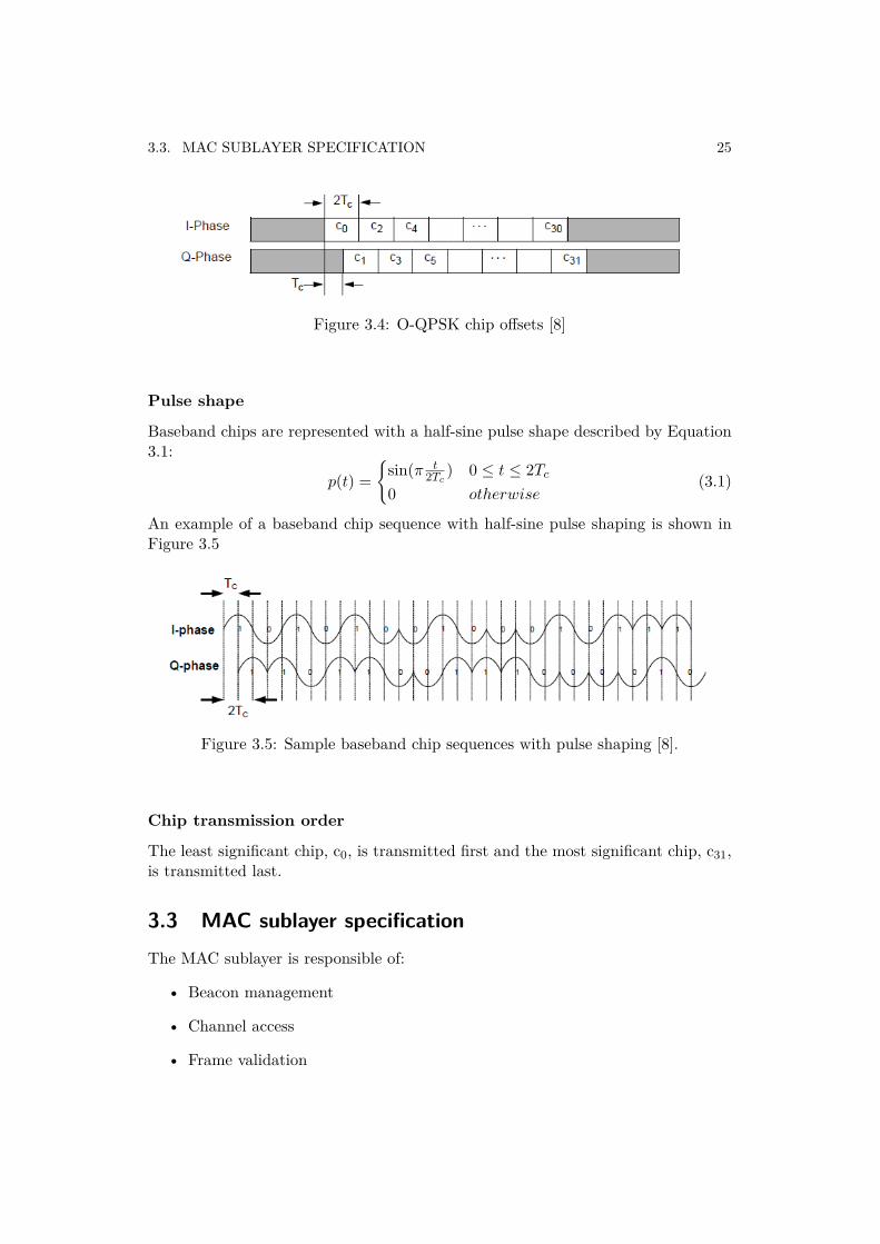
O-QPSK modulation
The chip sequences of each data symbol shall be modulated by using O-QPSKwith half-sine pulse shaping. To form the offset between I-phase and Q-phase chipmodulation, the Q-phase chips (odd-indexed chips) shall be delayed by Tc withrespect to the I-phase chips (even-indexed chips) as shown in Figure 3.4. Tc is theinverse of the chip rate (nominally 2.0 Mchips/s), which is 32 times the symbol rate.
3.3. MAC SUBLAYER SPECIFICATION 25
Figure 3.4: O-QPSK chip offsets [8]
Pulse shape
Baseband chips are represented with a half-sine pulse shape described by Equation3.1:
p(t) ={
sin(π t2Tc
) 0 ≤ t ≤ 2Tc
0 otherwise(3.1)
An example of a baseband chip sequence with half-sine pulse shaping is shown inFigure 3.5
Figure 3.5: Sample baseband chip sequences with pulse shaping [8].
Chip transmission order
The least significant chip, c0, is transmitted first and the most significant chip, c31,is transmitted last.
3.3 MAC sublayer specificationThe MAC sublayer is responsible of:
• Beacon management
• Channel access
• Frame validation
26 CHAPTER 3. IEEE 802.15.4 PROTOCOL
• Acknowledged frame delivery
• Association and disassociation
• GTS management
• Security services
All these services are detailed in [8]. In this section it is presented a general overviewof the main MAC features.
3.3.1 Channel access
Superframe structure
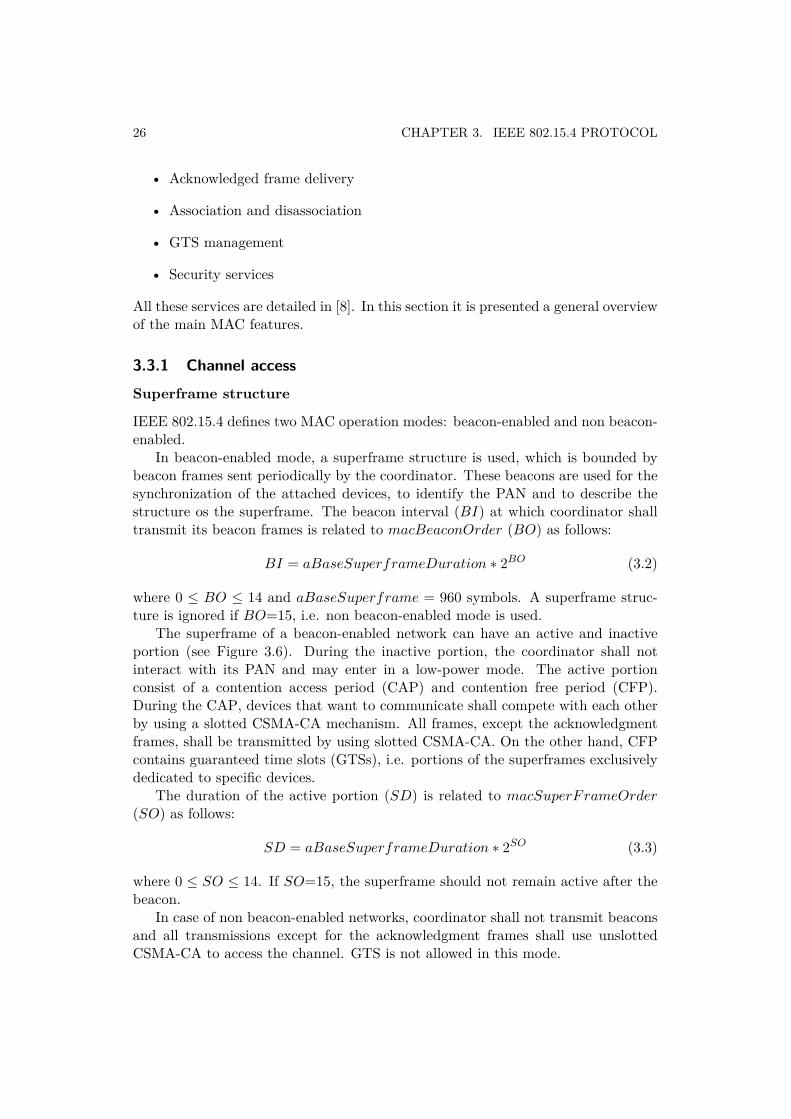
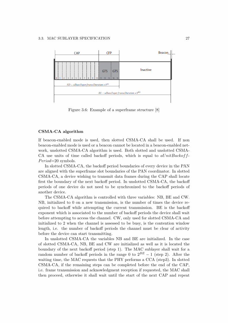
IEEE 802.15.4 defines two MAC operation modes: beacon-enabled and non beacon-enabled.
In beacon-enabled mode, a superframe structure is used, which is bounded bybeacon frames sent periodically by the coordinator. These beacons are used for thesynchronization of the attached devices, to identify the PAN and to describe thestructure os the superframe. The beacon interval (BI) at which coordinator shalltransmit its beacon frames is related to macBeaconOrder (BO) as follows:
BI = aBaseSuperframeDuration ∗ 2BO (3.2)
where 0 ≤ BO ≤ 14 and aBaseSuperframe = 960 symbols. A superframe struc-ture is ignored if BO=15, i.e. non beacon-enabled mode is used.
The superframe of a beacon-enabled network can have an active and inactiveportion (see Figure 3.6). During the inactive portion, the coordinator shall notinteract with its PAN and may enter in a low-power mode. The active portionconsist of a contention access period (CAP) and contention free period (CFP).During the CAP, devices that want to communicate shall compete with each otherby using a slotted CSMA-CA mechanism. All frames, except the acknowledgmentframes, shall be transmitted by using slotted CSMA-CA. On the other hand, CFPcontains guaranteed time slots (GTSs), i.e. portions of the superframes exclusivelydedicated to specific devices.
The duration of the active portion (SD) is related to macSuperFrameOrder(SO) as follows:
SD = aBaseSuperframeDuration ∗ 2SO (3.3)
where 0 ≤ SO ≤ 14. If SO=15, the superframe should not remain active after thebeacon.
In case of non beacon-enabled networks, coordinator shall not transmit beaconsand all transmissions except for the acknowledgment frames shall use unslottedCSMA-CA to access the channel. GTS is not allowed in this mode.
3.3. MAC SUBLAYER SPECIFICATION 27
Figure 3.6: Example of a superframe structure [8]
CSMA-CA algorithm
If beacon-enabled mode is used, then slotted CSMA-CA shall be used. If nonbeacon-enabled mode is used or a beacon cannot be located in a beacon-enabled net-work, unslotted CSMA-CA algorithm is used. Both slotted and unslotted CSMA-CA use units of time called backoff periods, which is equal to aUnitBackoff -Period=20 symbols.
In slotted CSMA-CA, the backoff period boundaries of every device in the PANare aligned with the superframe slot boundaries of the PAN coordinator. In slottedCSMA-CA, a device wishing to transmit data frames during the CAP shall locatefirst the boundary of the next backoff period. In unslotted CSMA-CA, the backoffperiods of one device do not need to be synchronized to the backoff periods ofanother device.
The CSMA-CA algorithm is controlled with three variables: NB, BE and CW.NB, initialized to 0 on a new transmission, is the number of times the device re-quired to backoff while attempting the current transmission. BE is the backoffexponent which is associated to the number of backoff periods the device shall waitbefore attempting to access the channel. CW, only used for slotted CSMA-CA andinitialized to 2 when the channel is assessed to be busy, is the contention windowlength, i.e. the number of backoff periods the channel must be clear of activitybefore the device can start transmitting.
In unslotted CSMA-CA the variables NB and BE are initialized. In the caseof slotted CSMA-CA, NB, BE and CW are initialized as well as it is located theboundary of the next backoff period (step 1). The MAC sublayer shall wait for arandom number of backoff periods in the range 0 to 2BE − 1 (step 2). After thewaiting time, the MAC requests that the PHY performs a CCA (step3). In slottedCSMA-CA, if the remaining steps can be completed before the end of the CAP,i.e. frame transmission and acknowledgment reception if requested, the MAC shallthen proceed, otherwise it shall wait until the start of the next CAP and repeat
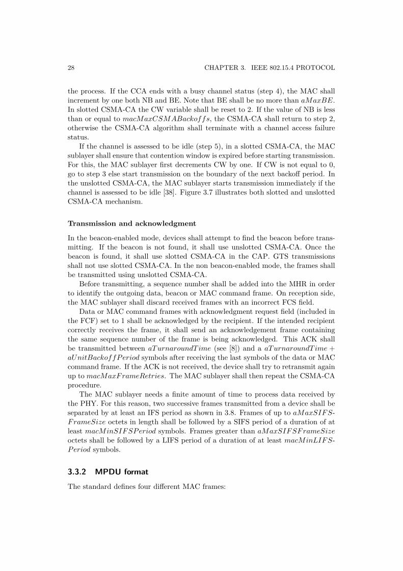
28 CHAPTER 3. IEEE 802.15.4 PROTOCOL
the process. If the CCA ends with a busy channel status (step 4), the MAC shallincrement by one both NB and BE. Note that BE shall be no more than aMaxBE.In slotted CSMA-CA the CW variable shall be reset to 2. If the value of NB is lessthan or equal to macMaxCSMABackoffs, the CSMA-CA shall return to step 2,otherwise the CSMA-CA algorithm shall terminate with a channel access failurestatus.
If the channel is assessed to be idle (step 5), in a slotted CSMA-CA, the MACsublayer shall ensure that contention window is expired before starting transmission.For this, the MAC sublayer first decrements CW by one. If CW is not equal to 0,go to step 3 else start transmission on the boundary of the next backoff period. Inthe unslotted CSMA-CA, the MAC sublayer starts transmission immediately if thechannel is assessed to be idle [38]. Figure 3.7 illustrates both slotted and unslottedCSMA-CA mechanism.
Transmission and acknowledgment
In the beacon-enabled mode, devices shall attempt to find the beacon before trans-mitting. If the beacon is not found, it shall use unslotted CSMA-CA. Once thebeacon is found, it shall use slotted CSMA-CA in the CAP. GTS transmissionsshall not use slotted CSMA-CA. In the non beacon-enabled mode, the frames shallbe transmitted using unslotted CSMA-CA.
Before transmitting, a sequence number shall be added into the MHR in orderto identify the outgoing data, beacon or MAC command frame. On reception side,the MAC sublayer shall discard received frames with an incorrect FCS field.
Data or MAC command frames with acknowledgment request field (included inthe FCF) set to 1 shall be acknowledged by the recipient. If the intended recipientcorrectly receives the frame, it shall send an acknowledgement frame containingthe same sequence number of the frame is being acknowledged. This ACK shallbe transmitted between aTurnaroundT ime (see [8]) and a aTurnaroundT ime +aUnitBackoffPeriod symbols after receiving the last symbols of the data or MACcommand frame. If the ACK is not received, the device shall try to retransmit againup to macMaxFrameRetries. The MAC sublayer shall then repeat the CSMA-CAprocedure.
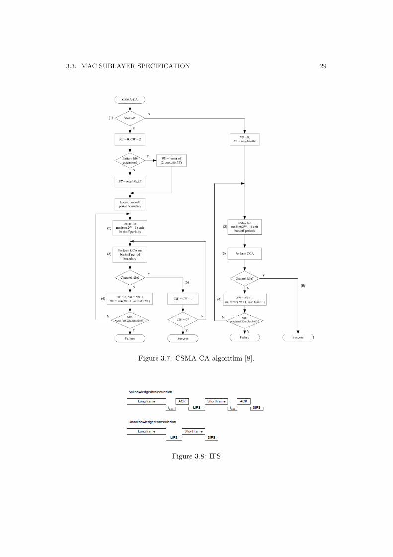
The MAC sublayer needs a finite amount of time to process data received bythe PHY. For this reason, two successive frames transmitted from a device shall beseparated by at least an IFS period as shown in 3.8. Frames of up to aMaxSIFS-FrameSize octets in length shall be followed by a SIFS period of a duration of atleast macMinSIFSPeriod symbols. Frames greater than aMaxSIFSFrameSizeoctets shall be followed by a LIFS period of a duration of at least macMinLIFS-Period symbols.
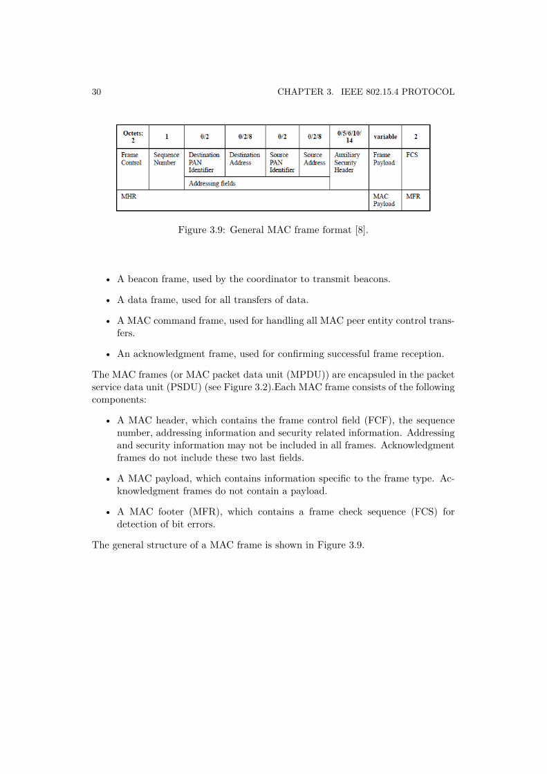
3.3.2 MPDU format
The standard defines four different MAC frames:
3.3. MAC SUBLAYER SPECIFICATION 29
Figure 3.7: CSMA-CA algorithm [8].
Figure 3.8: IFS
30 CHAPTER 3. IEEE 802.15.4 PROTOCOL
Figure 3.9: General MAC frame format [8].
• A beacon frame, used by the coordinator to transmit beacons.
• A data frame, used for all transfers of data.
• A MAC command frame, used for handling all MAC peer entity control trans-fers.
• An acknowledgment frame, used for confirming successful frame reception.
The MAC frames (or MAC packet data unit (MPDU)) are encapsuled in the packetservice data unit (PSDU) (see Figure 3.2).Each MAC frame consists of the followingcomponents:
• A MAC header, which contains the frame control field (FCF), the sequencenumber, addressing information and security related information. Addressingand security information may not be included in all frames. Acknowledgmentframes do not include these two last fields.
• A MAC payload, which contains information specific to the frame type. Ac-knowledgment frames do not contain a payload.
• A MAC footer (MFR), which contains a frame check sequence (FCS) fordetection of bit errors.
The general structure of a MAC frame is shown in Figure 3.9.
Chapter 4Analytical model for IEEE
802.15.4 MAC protocol
4.1 Background
In this chapter we introduce the accurate analytical model for IEEE 802.15.4 MACprotocol in [7]. This model is used for both evaluation of the simulator and TKN15.4implementation.
In the existing literature, there are other works for modeling the IEEE 802.15.4MAC. Some of them are based on Bianchi’s Markov chain model for the IEEE 802.11MAC [39] since it uses a similar CSMA-CA mechanism. In this model, saturatedtraffic conditions are assumed and the models of the IEEE 802.15.4 MAC basedon Bianchi’s work, such as in [40], [41] and [42] show inaccurate simulation resultsin conditions of unsaturated traffic, which is more suitable for WSN applications.Moreover, they do not consider some key factors of the IEEE 802.15.4 MAC pro-tocol, such as the active and inactive periods. In [43] and [44] active and inactiveperiods are considered. In [43] uplink and downlink traffic are considered, but de-vices have infinite buffers. It also shows inaccurate simulation results. Moreover,the power consumption, reliability and delay performance are not considered. In[44], a key factor, such as the length of data and ACK packets is not considered.
In contrast of these works, the model in [7] takes into account all the key factorsof the IEEE 802.15.4 MAC protocol, not only the transmissions during the CAPby using the CSMA-CA mechanism but also the transmissions during the CFP.However, in this thesis we only focus on the evaluation of the CSMA-CA algorithm.
4.2 System model
We consider a star network with a coordinator and N devices. Every device con-tends to send data packet to the coordinator, which acts as a data sink. Devicesasynchronously generate packets with probability ηt after it successfully has sent a
31
32 CHAPTER 4. ANALYTICAL MODEL FOR IEEE 802.15.4 MAC PROTOCOL
packet or has discarded a packet previously scheduled for transmission. If a newpacket is not generated, then it tries to generate another one after hTb with probabil-ity ηp, where h is an integer and Tb is time corresponding to aUnitBackoffPeriod(20 symbols).
In [7], when a device generates a packet, it generates a non time-critical datapacket (i.e. packet to be transmitted in the CAP) with probability ηd, and a time-critical data packet (i.e. packet to be transmitted in the CFP) with probability1 − ηd. For the experimental evaluation of TKN15.4, since the CAP is the focusof the performance analysis, only non time-critical packets are generated (ηd = 1).Moreover, it will also be considered that ηt = ηp = η.
4.3 Performance analysis
In this section we briefly introduce a generalized Markov chain model of the slottedCSMA-CA mechanism of the beacon-enabled IEEE 8021.5.4 MAC.
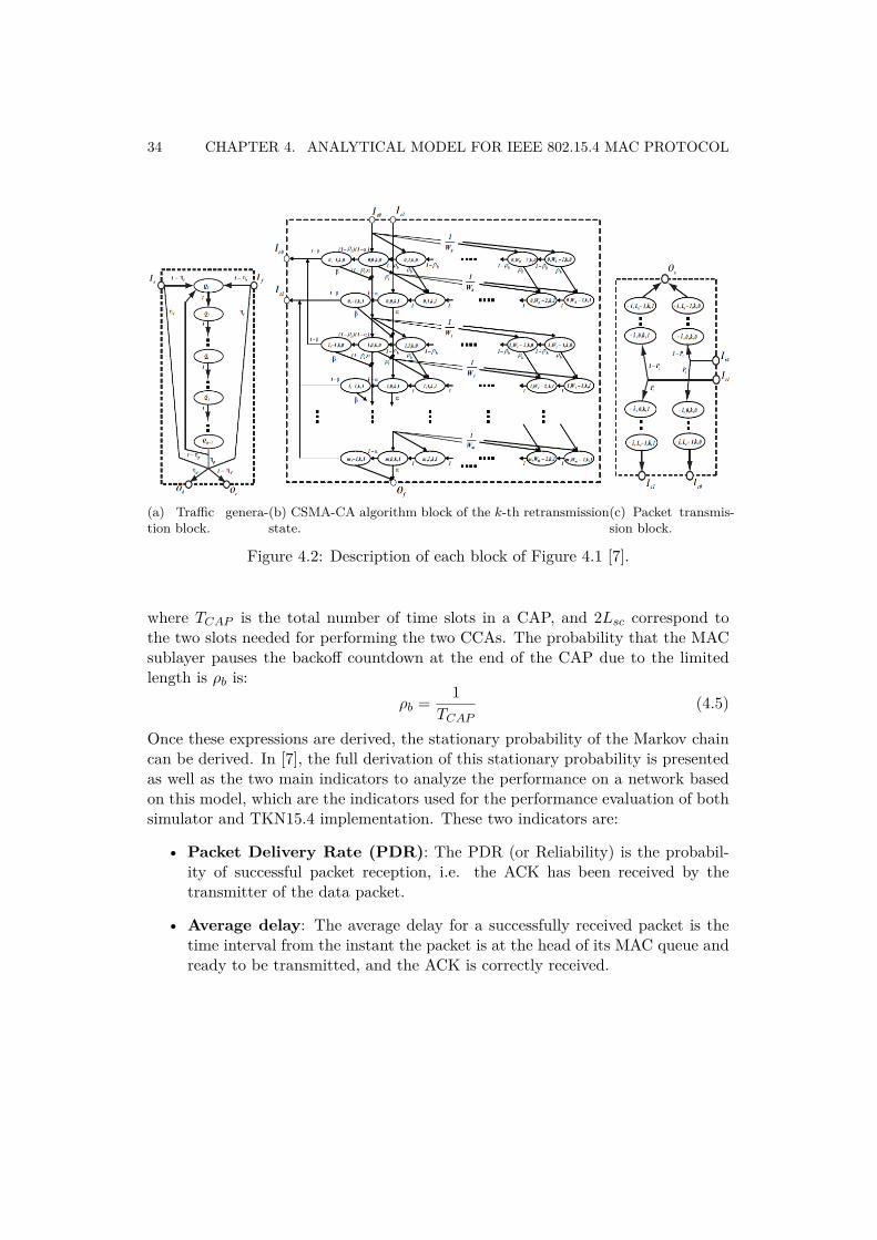
The state evolution of the Markov chain is defined by the stochastic processesb(t), c(t), e(t) and f(t) representing the backoff stage, the state of the backoffcounter, the state of retransmission counter and the state of deferred transmissionat time t (f(t) = 1 deferred, f(t) = 0 not deferred) due to the limited size of super-frame to transmit a packet. Considering (b(t),c(t),e(t),f(t)), it is used (i,j,k,l) todenote a particular state. Other general notations aremacMinBE , m0 (minimumvalue of the backoff exponent), macMaxCSMABackoffs , m (maximum num-ber of backoffs allowed), macMaxFrameRetries , n (maximum number of retriesallowed), macMaxBE , mb (maximum value of the backoff exponent), W0 , 2m0
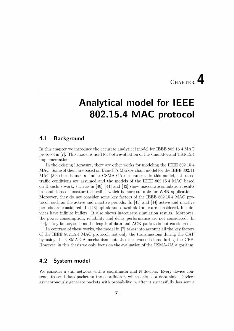
and Wm , 2min(m0+m,mb).Figure 4.1 shows the generalized Markov chain for a single device, which is
formed by three different blocks: traffic generation block, CSMA-CA algorithmblocks, and packet transmission blocks.
Considering the system model previously described, the traffic generation blockis shown in Figure 4.2a. The states Q0, Q1, ..., Qh−1 represent to the idle-queuestates when the device is waiting during hTb for the next packet generation time.After this time, the device generates a packet with probability ηp. This new packetcould be a non time-critical packet with probability ηd and a time-critical packetwith probability 1 − ηd. Then, the device performs the CSMA-CA algorithm tosend the generated packet. Figure 4.2b shows the different states of the CSMA-CAmechanism: states from (i,Wm − 1, k, l) to (i,W0 − 1, k, l) represent the backoffstates, and (i, 0, k, l) and (i,−1, k, l) the first CCA (CCA1) and the second CCA(CCA2) of the slotted CSMA-CA algorithm respectively. The channel is sensed tobe busy in CCA1 with probability α and in the CCA2 with probability β. If thedevice fails to obtain a clear channel due to repeated busy channel for macMax-CSMABackoffs times, then the packet is discarded. If the channel sensing issuccessful, then the device moves to the packet transmission block, which modelsthe successful transmissions and collisions within packets. Figure 4.2c shows the
4.3. PERFORMANCE ANALYSIS 33
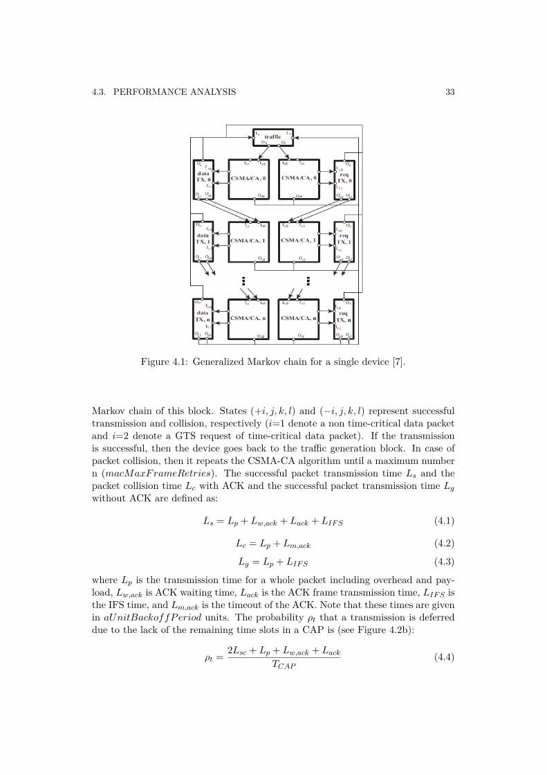
Figure 4.1: Generalized Markov chain for a single device [7].
Markov chain of this block. States (+i, j, k, l) and (−i, j, k, l) represent successfultransmission and collision, respectively (i=1 denote a non time-critical data packetand i=2 denote a GTS request of time-critical data packet). If the transmissionis successful, then the device goes back to the traffic generation block. In case ofpacket collision, then it repeats the CSMA-CA algorithm until a maximum numbern (macMaxFrameRetries). The successful packet transmission time Ls and thepacket collision time Lc with ACK and the successful packet transmission time Lg
without ACK are defined as:
Ls = Lp + Lw,ack + Lack + LIF S (4.1)
Lc = Lp + Lm,ack (4.2)
Lg = Lp + LIF S (4.3)
where Lp is the transmission time for a whole packet including overhead and pay-load, Lw,ack is ACK waiting time, Lack is the ACK frame transmission time, LIF S isthe IFS time, and Lm,ack is the timeout of the ACK. Note that these times are givenin aUnitBackoffPeriod units. The probability ρt that a transmission is deferreddue to the lack of the remaining time slots in a CAP is (see Figure 4.2b):
ρt = 2Lsc + Lp + Lw,ack + Lack
TCAP(4.4)
34 CHAPTER 4. ANALYTICAL MODEL FOR IEEE 802.15.4 MAC PROTOCOL
(a) Traffic genera-tion block.
(b) CSMA-CA algorithm block of the k-th retransmissionstate.
(c) Packet transmis-sion block.
Figure 4.2: Description of each block of Figure 4.1 [7].
where TCAP is the total number of time slots in a CAP, and 2Lsc correspond tothe two slots needed for performing the two CCAs. The probability that the MACsublayer pauses the backoff countdown at the end of the CAP due to the limitedlength is ρb is:
ρb = 1TCAP
(4.5)
Once these expressions are derived, the stationary probability of the Markov chaincan be derived. In [7], the full derivation of this stationary probability is presentedas well as the two main indicators to analyze the performance on a network basedon this model, which are the indicators used for the performance evaluation of bothsimulator and TKN15.4 implementation. These two indicators are:
• Packet Delivery Rate (PDR): The PDR (or Reliability) is the probabil-ity of successful packet reception, i.e. the ACK has been received by thetransmitter of the data packet.
• Average delay: The average delay for a successfully received packet is thetime interval from the instant the packet is at the head of its MAC queue andready to be transmitted, and the ACK is correctly received.
Chapter 5Simulator development using
MATLAB
5.1 Motivation
In Section 2.3.3 we summarized the main WSN simulators. Despite MATLAB isthe most attractive simulation environment due to its ease of use, only a few WSNtools are available for this platform. Two of the most notable ones are Prowlerand TrueTime. However, the MAC sublayer model of Prowler is very simplifiedand it is not based on the standard IEEE 802.15.4. TrueTime includes some IEEE802.15.4 beacon-enabled mode functionalities but they have not been contrastedwith theoretical models. Furthermore, it is not very easy to use or extend newfunctionalities since it is based on MATLAB-SIMULINK.
In this chapter we present a new WSN simulator in MATLAB based on IEEE802.15.4 PHY and MAC layers. The main goal is to dispose a simulator which givesreliable results contrasted with theoretical models and easy to be extended for userconvenience. Moreover, a GUI is added to give the user the possibility to drawnetwork topologies.
Section 5.2 presents the main functionalities of the simulator as well as thesimplifications that has been considered. The code architecture is summarized inSection 5.3. Finally, the performance of the simulator is evaluated.
5.2 Functional overview
5.2.1 Physical and MAC layer models
Physical layer model
The physical layer defined by the standard for the 2450 MHz band was thoughtto be implemented in detail, i.e. the whole encoding process described in Section3.2.2 as well as using accurate channel models which consider the path loss due to
35
36 CHAPTER 5. SIMULATOR DEVELOPMENT USING MATLAB
distance and slow and fast fading, characteristics of a wireless channel. However,considering the increasing computational cost it involves, a simplified physical modelhas implemented.
Two radio propagation models are used, and ideal channel and a path loss model,which determine the strength of the transmitted signal in a given point of the space.Both models are deterministic but probabilistic models can be added easily. Theideal channel does not consider any attenuation of the signal, i.e. the receptionpower is the same than transmission power, independently of the points transmitterand receiver are situated. The path loss model is the one used in the standard forsimulations in the 2450 MHz band, which expression is as following:
PL(d) ={
40.2 + 20 log(d) d ≤ 858.5 + 20 log(d/8) d > 8
(5.1)
On reception, it is considered that a packet is successfully received if the SINRis greater than a threshold, where SINR is given by:
SINR = Prec(i, j)σ2
n +∑
k 6=jPrec(i, k) (5.2)
where σ2n is the noise variance, Prec(i, j) is the received power in node i from node j
and Prec(i, k) is the interference power received in node i from the potential collidingnodes. These received power depend on the relative distance between receiver andtransmitter and the channel model. If the SINR is below the reception threshold,the packet is not received due to a low SNR or a high interference power (collision).The reception threshold corresponds to a BER= 10−3, which expression is given in[8]:
BER = 815 × 1
16 ×16∑
k=2−1k
(16k
)e20×SINR×( 1
k−1) (5.3)
For the CCA mechanism, the channel is sensed idle if the total received power in thenode plus the noise power is below the sensitivity of the receiver, which is specifiedin the standard. The event-based nature of the simulator shall also be considered forhaving a realistic CCA. The CCA procedure of the simulator consists of two events.The first one is created when CCA is supposed to start and in that time it analyzesthe frames that are currently being transmitted. However, in a non beacon-enabledmode it could happen that new frames start being transmitted during the definedsensing interval so is needed to create another event to check the availability of thechannel after the sensing time. The first event is also mandatory as it could occurthat frames being transmitted end the transmission during the sensing time so CCAwould not detect them in case of only having a CCA checking event at the end ofthe sensing time.
5.3. SIMULATOR ARCHITECTURE 37
MAC sublayer model
The MAC sublayer fully implements the 802.15.4 CSMA-CA algorithm described inSection 3.3.1 for both beacon-enabled and non beacon-enabled mode. It has beenvalidated (see Section 5.4) by comparing its performance results with the analyticalmodel presented in Chapter 4. Furthermore, A MAC queue has been implementedfor store the packets scheduled for transmission.
5.2.2 Graphic user interface
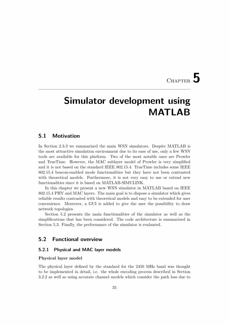
A Graphic User Interface (GUI) has been developed based on TORSHE GrapheditTool [45]. The GUI allows the user to draw network topologies easily and runsimulations.
The GUI is composed of two panels, the Graphedit Tool (Figure 5.1a) anda control panel (Figure 5.1b). By using Graphedit, user can place nodes and linkthem with edges forming different topologies. Topologies can be imported/exportedfor user convenience. Furthermore, the realistic distance based path loss model isoptional by inserting distance between nodes of a network. Graphedit Tool doesnot provide the distance between nodes. The original code has been modified toshow the distance between nodes when linking them with edges as well as the radiopropagation range according to the transmission power of the nodes. Note thatdespite allowing the linking function between nodes, the simulator is based on PHYand MAC layer of IEEE 802.15.4 standard and does not implement any networkprotocol so it does not take any routing action, leaving to the user the possibilityto define a routing protocol as an option. The second panel controls the GrapheditTool and allows the user the selection of the two different channel models, theideal channel or the path loss modeling channel. It also permits to change thetransmission power of the nodes.
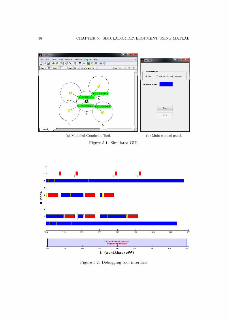
5.2.3 Debugging tools
A debugging tool has been added to the simulator. It allows the user to see graph-ically the PHY and MAC events registered during a simulation. An example ofthis tool is shown in Figure 5.2. It displays the events occurred when runninga simulation based on the system model described in Chapter 4, in which devicenodes contend to send data packets to the coordinator. Bars represent waiting time(Backoff), CCA time and transmission time. Small lines represent a new packetarrival, reception of a frame and timeout of the ACK.
5.3 Simulator architecture
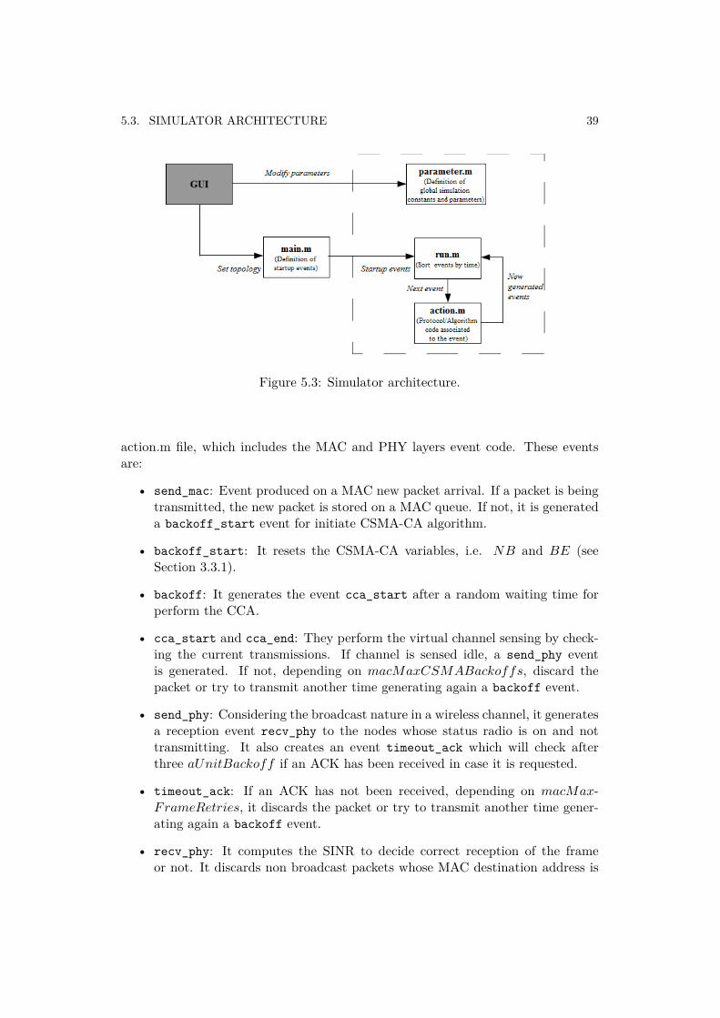
The basic files of the simulator aremain.m, run.m, action.m and parameter.m.The relation within these file is shown in Figure 5.3. The core of the simulator is the
38 CHAPTER 5. SIMULATOR DEVELOPMENT USING MATLAB
(a) Modified Graphedit Tool. (b) Main control panel.
Figure 5.1: Simulator GUI.
Figure 5.2: Debugging tool interface.
5.3. SIMULATOR ARCHITECTURE 39
Figure 5.3: Simulator architecture.
action.m file, which includes the MAC and PHY layers event code. These eventsare:
• send_mac: Event produced on a MAC new packet arrival. If a packet is beingtransmitted, the new packet is stored on a MAC queue. If not, it is generateda backoff_start event for initiate CSMA-CA algorithm.
• backoff_start: It resets the CSMA-CA variables, i.e. NB and BE (seeSection 3.3.1).
• backoff: It generates the event cca_start after a random waiting time forperform the CCA.
• cca_start and cca_end: They perform the virtual channel sensing by check-ing the current transmissions. If channel is sensed idle, a send_phy eventis generated. If not, depending on macMaxCSMABackoffs, discard thepacket or try to transmit another time generating again a backoff event.
• send_phy: Considering the broadcast nature in a wireless channel, it generatesa reception event recv_phy to the nodes whose status radio is on and nottransmitting. It also creates an event timeout_ack which will check afterthree aUnitBackoff if an ACK has been received in case it is requested.
• timeout_ack: If an ACK has not been received, depending on macMax-FrameRetries, it discards the packet or try to transmit another time gener-ating again a backoff event.
• recv_phy: It computes the SINR to decide correct reception of the frameor not. It discards non broadcast packets whose MAC destination address is
40 CHAPTER 5. SIMULATOR DEVELOPMENT USING MATLAB
different than the receiver node MAC address. If the frame is not discarded,it creates a recv_mac event.
• recv_mac: It checks the type of the frame, i.e. data packet or ACK frame. Ifit is a data packet, it generates a send_phy event for transmit the ACK frameif requested. recv_mac also discards received ACKs with a sequence numberthat does not match the sequence number of the transmitted frame.
Once understood these events, it is easy to add new ones to action.m defining userprotocols for network layer or above.
The main.m is responsible for load the space topology defined in the GrapheditTool and is the file in which the user sets the startup simulation events. It callsthe function run.m, which is the event driven simulation loop that initiates thesimulation from the startup events by calling and controlling action.m
IEEE 802.15.4 PHY and MAC and channel model parameters and constants aredefined in parameters.m.
5.4 Performance evaluation
In this section we evaluate the performance of the simulator in terms of PDR andaverage delay and compare with theoretical results given by the analytical modeldescribed in Chapter 4.
Non beacon-enabled mode
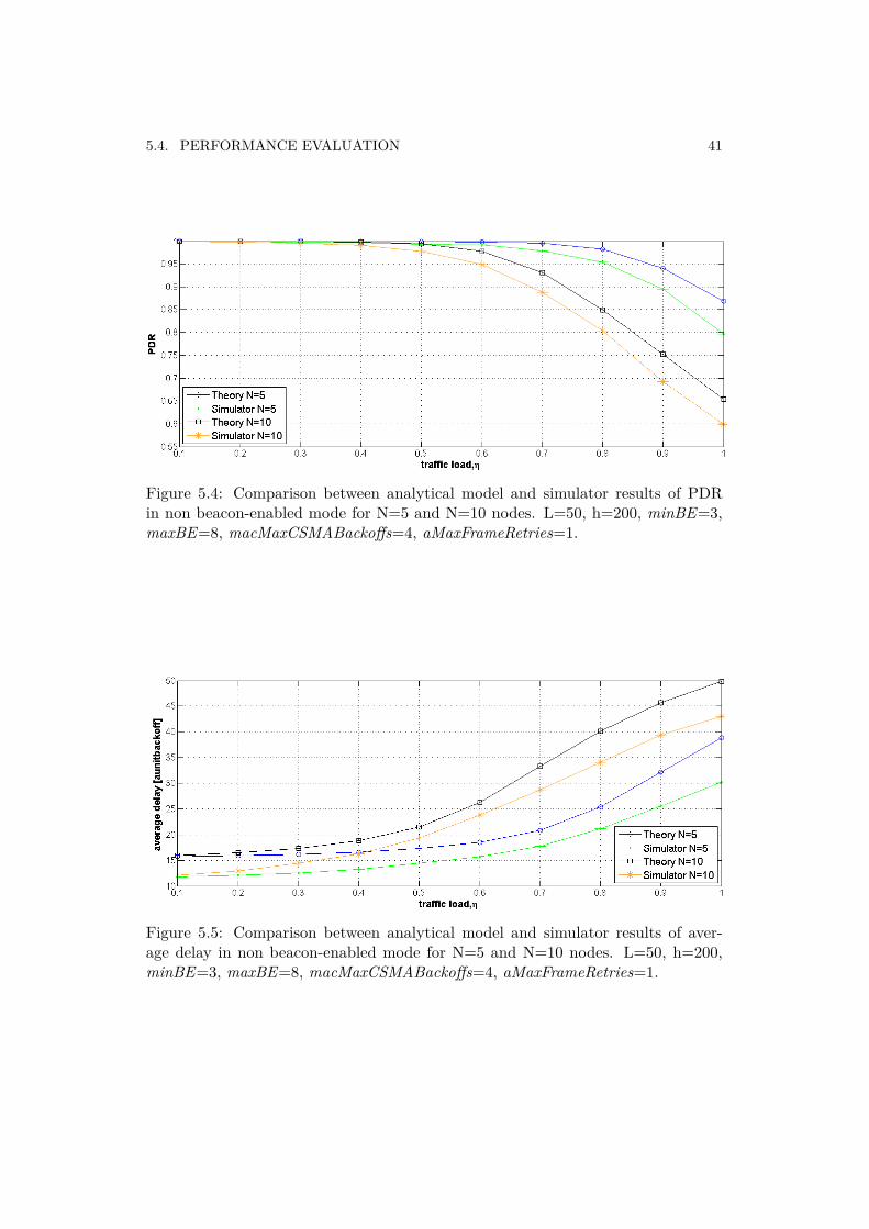
Here it is presented the performance results of the non beacon-enabled mode of thesimulator for the system model detailed in Section 4.2 for both N=5 and N=10device nodes. PDR and average delay are shown in Figures 5.4 and 5.5 respec-tively. The sampling interval h is 200 and the packet length is 50 bytes. The MACparameters are minBE = 3, maxBE = 8, macMaxCSMABackoffs = 4 andaMaxFrameRetries = 1.
The non beacon-enabled PDR and average delay results of the simulator showa good performance with respect of the analytical model, for both systems modelswith N=5 and N=10. Remark that in theory aUnitBackoffPeriod is consideredas the underlying minimum time, i.e. all events happen at boundary slots evenin the non beacon-enabled mode, in which the boundary slots in that case are notsynchronized within nodes. For example, in case of a node performs a CCA, it waitsuntil its next boundary slot to take the next MAC action. In case of the simulator,after a time of 8 symbols for the CCA, which is the time specified by the standard,it does not wait until next boundary slot to take the next MAC action. For thisreason, the average delay curves of theory show a tendency more increasing, sincethere is an accumulated time due to this waiting time.
5.4. PERFORMANCE EVALUATION 41
Figure 5.4: Comparison between analytical model and simulator results of PDRin non beacon-enabled mode for N=5 and N=10 nodes. L=50, h=200, minBE=3,maxBE=8, macMaxCSMABackoffs=4, aMaxFrameRetries=1.
Figure 5.5: Comparison between analytical model and simulator results of aver-age delay in non beacon-enabled mode for N=5 and N=10 nodes. L=50, h=200,minBE=3, maxBE=8, macMaxCSMABackoffs=4, aMaxFrameRetries=1.
42 CHAPTER 5. SIMULATOR DEVELOPMENT USING MATLAB
Beacon-enabled mode
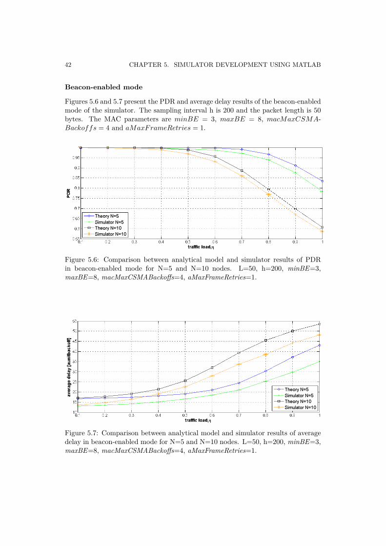
Figures 5.6 and 5.7 present the PDR and average delay results of the beacon-enabledmode of the simulator. The sampling interval h is 200 and the packet length is 50bytes. The MAC parameters are minBE = 3, maxBE = 8, macMaxCSMA-Backoffs = 4 and aMaxFrameRetries = 1.
Figure 5.6: Comparison between analytical model and simulator results of PDRin beacon-enabled mode for N=5 and N=10 nodes. L=50, h=200, minBE=3,maxBE=8, macMaxCSMABackoffs=4, aMaxFrameRetries=1.
Figure 5.7: Comparison between analytical model and simulator results of averagedelay in beacon-enabled mode for N=5 and N=10 nodes. L=50, h=200, minBE=3,maxBE=8, macMaxCSMABackoffs=4, aMaxFrameRetries=1.
5.5. SUMMARY 43
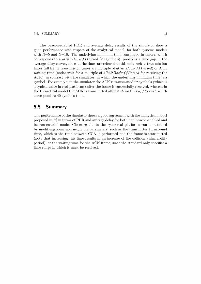
The beacon-enabled PDR and average delay results of the simulator show agood performance with respect of the analytical model, for both systems modelswith N=5 and N=10. The underlying minimum time considered in theory, whichcorresponds to a aUnitBackoffPeriod (20 symbols), produces a time gap in theaverage delay curves, since all the times are referred to this unit such as transmissiontimes (all frame transmission times are multiple of aUnitBackoffPeriod) or ACKwaiting time (nodes wait for a multiple of aUnitBackoffPeriod for receiving theACK), in contrast with the simulator, in which the underlying minimum time is asymbol. For example, in the simulator the ACK is transmitted 22 symbols (which isa typical value in real platforms) after the frame is successfully received, whereas inthe theoretical model the ACK is transmitted after 2 aUnitBackoffPeriod, whichcorrespond to 40 symbols time.
5.5 SummaryThe performance of the simulator shows a good agreement with the analytical modelproposed in [7] in terms of PDR and average delay for both non beacon-enabled andbeacon-enabled mode. Closer results to theory or real platforms can be attainedby modifying some non negligible parameters, such as the transmitter turnaroundtime, which is the time between CCA is performed and the frame is transmitted(note that increasing this time results in an increase of the collision vulnerabilityperiod), or the waiting time for the ACK frame, since the standard only specifies atime range in which it must be received.

Chapter 6Experimental evaluation of
TKN15.4
6.1 MotivationTKN15.4 is an advanced implementation of the IEEE 802.15.4 standard. In contrastof OpenZB-IPP Hurray implementation, in which important known issues couldaffect the correct operation of the system, only minor bugs have been reportedin TKN15.4 implementation. Note that at this time, security services and GTSmechanism are included in the implementation, which is provided as an open-sourcecode in TinyOS 2.1 release [46]. GTS was also implemented, evaluated and tested in[18]. However, as reported in its technical report, TKN15.4 must be evaluated andvalidated by comparing its performance with theoretical results. In this section, theTKN15.4 performance of the non beacon-enabled mode as well as the performance ofthe CAP in the beacon-enabled mode is analyzed in terms of PDR and average delayand compared with the analytical model presented in the previous chapter. First, anoverview of the TKN15.4 code architecture is presented for a better understandingof it. Then, performance of TKN15.4 is studied.
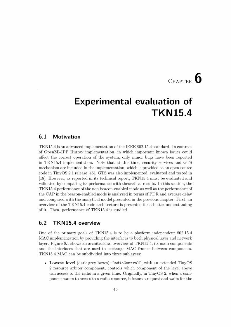
6.2 TKN15.4 overviewOne of the primary goals of TKN15.4 is to be a platform independent 802.15.4MAC implementation by providing the interfaces to both physical layer and networklayer. Figure 6.1 shows an architectural overview of TKN15.4, its main componentsand the interfaces that are used to exchange MAC frames between components.TKN15.4 MAC can be subdivided into three sublayers:
• Lowest level (dark grey boxes): RadioControlP, with an extended TinyOS2 resource arbiter component, controls which component of the level abovecan access to the radio in a given time. Originally, in TinyOS 2, when a com-ponent wants to access to a radio resource, it issues a request and waits for the
45
46 CHAPTER 6. EXPERIMENTAL EVALUATION OF TKN15.4
Figure 6.1: TKN15.4 code architecture
signal granted() before it can use the resource exclusively. The transition ofthe resource ownership from one component to another may take an arbitrarytime and hence, is suboptimal in beacon-enabled mode since timing is thekey factor for a correct operation. For example, the radio of a coordinatorshould be switched to receive mode after a beacon has been transmitted. Ifthe component responsible for managing the CAP is granted the access tothe radio too late (because there are other tasks served before), then incom-ing frames may be lost. TKN15.4 enhances the TinyOS resource arbitrationmodel by allowing a component that owns the radio resource to dynamicallytransfer the ownership to a specific other component. This is more suitablein a beacon-enabled mode as operation is defined in a superframe structureand the component which owns the radio resource knows the next componentinvolved in the synchronization, CAP or CFP operation.
• Second level components (medium grey boxes): Represent the differentparts of a superframe: the BeaconTransmitP/ BeaconSynchronizeP compo-nents are responsible for transmission/ reception of a beacon frame; Dispatch-SlottedCsmaP controls frame transmission and reception during the CAPwhile NoCoordCfpP/ NoDeviceCfpP are responsible for the CFP. In non beacon-enabled mode, DispatchUnslottedCsmaP is responsible for frame transmis-sion and reception.
• Top level components (white boxes): Implement the remaining MAC datamanagement services.
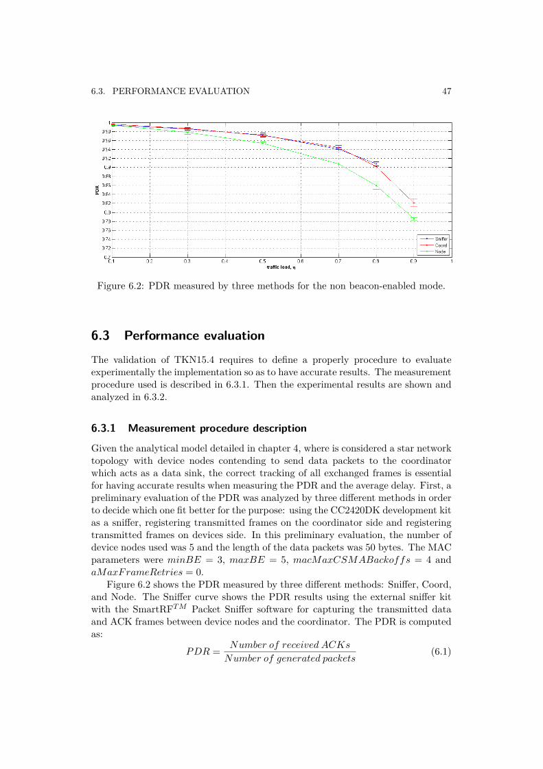
6.3. PERFORMANCE EVALUATION 47
Figure 6.2: PDR measured by three methods for the non beacon-enabled mode.
6.3 Performance evaluation
The validation of TKN15.4 requires to define a properly procedure to evaluateexperimentally the implementation so as to have accurate results. The measurementprocedure used is described in 6.3.1. Then the experimental results are shown andanalyzed in 6.3.2.
6.3.1 Measurement procedure description
Given the analytical model detailed in chapter 4, where is considered a star networktopology with device nodes contending to send data packets to the coordinatorwhich acts as a data sink, the correct tracking of all exchanged frames is essentialfor having accurate results when measuring the PDR and the average delay. First, apreliminary evaluation of the PDR was analyzed by three different methods in orderto decide which one fit better for the purpose: using the CC2420DK development kitas a sniffer, registering transmitted frames on the coordinator side and registeringtransmitted frames on devices side. In this preliminary evaluation, the number ofdevice nodes used was 5 and the length of the data packets was 50 bytes. The MACparameters were minBE = 3, maxBE = 5, macMaxCSMABackoffs = 4 andaMaxFrameRetries = 0.
Figure 6.2 shows the PDR measured by three different methods: Sniffer, Coord,and Node. The Sniffer curve shows the PDR results using the external sniffer kitwith the SmartRFT M Packet Sniffer software for capturing the transmitted dataand ACK frames between device nodes and the coordinator. The PDR is computedas:
PDR = Number of received ACKs
Number of generated packets(6.1)
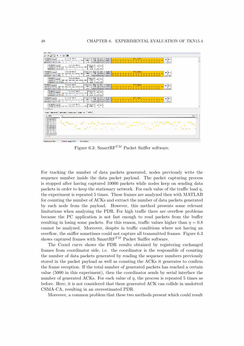
48 CHAPTER 6. EXPERIMENTAL EVALUATION OF TKN15.4
Figure 6.3: SmartRFT M Packet Sniffer software.
For tracking the number of data packets generated, nodes previously write thesequence number inside the data packet payload. The packet capturing processis stopped after having captured 10000 packets while nodes keep on sending datapackets in order to keep the stationary network. For each value of the traffic load η,the experiment is repeated 5 times. These frames are analyzed then with MATLABfor counting the number of ACKs and extract the number of data packets generatedby each node from the payload. However, this method presents some relevantlimitations when analyzing the PDR. For high traffic there are overflow problemsbecause the PC application is not fast enough to read packets from the bufferresulting in losing some packets. For this reason, traffic values higher than η = 0.8cannot be analyzed. Moreover, despite in traffic conditions where not having anoverflow, the sniffer sometimes could not capture all transmitted frames. Figure 6.3shows captured frames with SmartRFT M Packet Sniffer software.
The Coord curve shows the PDR results obtained by registering exchangedframes from coordinator side, i.e. the coordinator is the responsible of countingthe number of data packets generated by reading the sequence numbers previouslystored in the packet payload as well as counting the ACKs it generates to confirmthe frame reception. If the total number of generated packets has reached a certainvalue (5000 in this experiment), then the coordinator sends by serial interface thenumber of generated ACKs. For each value of η, the process is repeated 5 times asbefore. Here, it is not considered that these generated ACK can collide in unslottedCSMA-CA, resulting in an overestimated PDR.
Moreover, a common problem that these two methods present which could result
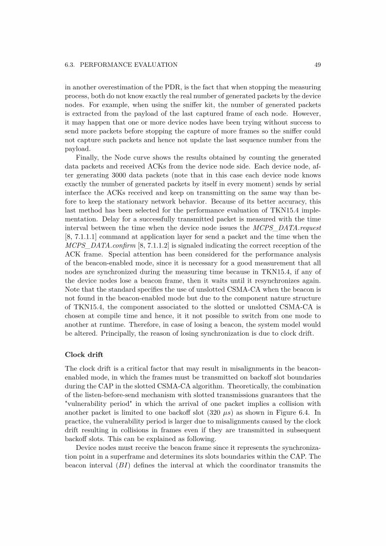
6.3. PERFORMANCE EVALUATION 49
in another overestimation of the PDR, is the fact that when stopping the measuringprocess, both do not know exactly the real number of generated packets by the devicenodes. For example, when using the sniffer kit, the number of generated packetsis extracted from the payload of the last captured frame of each node. However,it may happen that one or more device nodes have been trying without success tosend more packets before stopping the capture of more frames so the sniffer couldnot capture such packets and hence not update the last sequence number from thepayload.
Finally, the Node curve shows the results obtained by counting the generateddata packets and received ACKs from the device node side. Each device node, af-ter generating 3000 data packets (note that in this case each device node knowsexactly the number of generated packets by itself in every moment) sends by serialinterface the ACKs received and keep on transmitting on the same way than be-fore to keep the stationary network behavior. Because of its better accuracy, thislast method has been selected for the performance evaluation of TKN15.4 imple-mentation. Delay for a successfully transmitted packet is measured with the timeinterval between the time when the device node issues the MCPS_DATA.request[8, 7.1.1.1] command at application layer for send a packet and the time when theMCPS_DATA.confirm [8, 7.1.1.2] is signaled indicating the correct reception of theACK frame. Special attention has been considered for the performance analysisof the beacon-enabled mode, since it is necessary for a good measurement that allnodes are synchronized during the measuring time because in TKN15.4, if any ofthe device nodes lose a beacon frame, then it waits until it resynchronizes again.Note that the standard specifies the use of unslotted CSMA-CA when the beacon isnot found in the beacon-enabled mode but due to the component nature structureof TKN15.4, the component associated to the slotted or unslotted CSMA-CA ischosen at compile time and hence, it it not possible to switch from one mode toanother at runtime. Therefore, in case of losing a beacon, the system model wouldbe altered. Principally, the reason of losing synchronization is due to clock drift.
Clock drift
The clock drift is a critical factor that may result in misalignments in the beacon-enabled mode, in which the frames must be transmitted on backoff slot boundariesduring the CAP in the slotted CSMA-CA algorithm. Theoretically, the combinationof the listen-before-send mechanism with slotted transmissions guarantees that the"vulnerability period" in which the arrival of one packet implies a collision withanother packet is limited to one backoff slot (320 µs) as shown in Figure 6.4. Inpractice, the vulnerability period is larger due to misalignments caused by the clockdrift resulting in collisions in frames even if they are transmitted in subsequentbackoff slots. This can be explained as following.
Device nodes must receive the beacon frame since it represents the synchroniza-tion point in a superframe and determines its slots boundaries within the CAP. Thebeacon interval (BI) defines the interval at which the coordinator transmits the
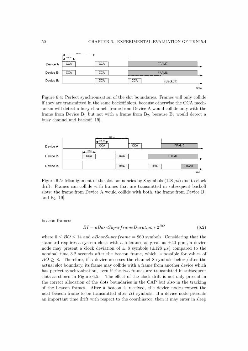
50 CHAPTER 6. EXPERIMENTAL EVALUATION OF TKN15.4
Figure 6.4: Perfect synchronization of the slot boundaries. Frames will only collideif they are transmitted in the same backoff slots, because otherwise the CCA mech-anism will detect a busy channel: frame from Device A would collide only with theframe from Device B1 but not with a frame from B2, because B2 would detect abusy channel and backoff [19].
Figure 6.5: Misalignment of the slot boundaries by 8 symbols (128 µs) due to clockdrift. Frames can collide with frames that are transmitted in subsequent backoffslots: the frame from Device A would collide with both, the frame from Device B1and B2 [19].
beacon frames:BI = aBaseSuperframeDuration ∗ 2BO (6.2)
where 0 ≤ BO ≤ 14 and aBaseSuperframe = 960 symbols. Considering that thestandard requires a system clock with a tolerance as great as ±40 ppm, a devicenode may present a clock deviation of ± 8 symbols (±128 µs) compared to thenominal time 3.2 seconds after the beacon frame, which is possible for values ofBO ≥ 8. Therefore, if a device accesses the channel 8 symbols before/after theactual slot boundary, its frame may collide with a frame from another device whichhas perfect synchronization, even if the two frames are transmitted in subsequentslots as shown in Figure 6.5. The effect of the clock drift is not only present inthe correct allocation of the slots boundaries in the CAP but also in the trackingof the beacon frames. After a beacon is received, the device nodes expect thenext beacon frame to be transmitted after BI symbols. If a device node presentsan important time drift with respect to the coordinator, then it may enter in sleep
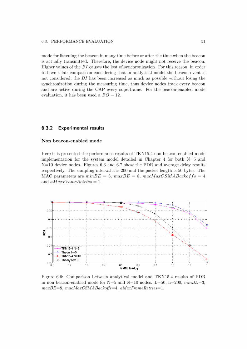
6.3. PERFORMANCE EVALUATION 51
mode for listening the beacon in many time before or after the time when the beaconis actually transmitted. Therefore, the device node might not receive the beacon.Higher values of the BI causes the lost of synchronization. For this reason, in orderto have a fair comparison considering that in analytical model the beacon event isnot considered, the BI has been increased as much as possible without losing thesynchronization during the measuring time, thus device nodes track every beaconand are active during the CAP every superframe. For the beacon-enabled modeevaluation, it has been used a BO = 12.
6.3.2 Experimental results
Non beacon-enabled mode
Here it is presented the performance results of TKN15.4 non beacon-enabled modeimplementation for the system model detailed in Chapter 4 for both N=5 andN=10 device nodes. Figures 6.6 and 6.7 show the PDR and average delay resultsrespectively. The sampling interval h is 200 and the packet length is 50 bytes. TheMAC parameters are minBE = 3, maxBE = 8, macMaxCSMABackoffs = 4and aMaxFrameRetries = 1.
Figure 6.6: Comparison between analytical model and TKN15.4 results of PDRin non beacon-enabled mode for N=5 and N=10 nodes. L=50, h=200, minBE=3,maxBE=8, macMaxCSMABackoffs=4, aMaxFrameRetries=1.
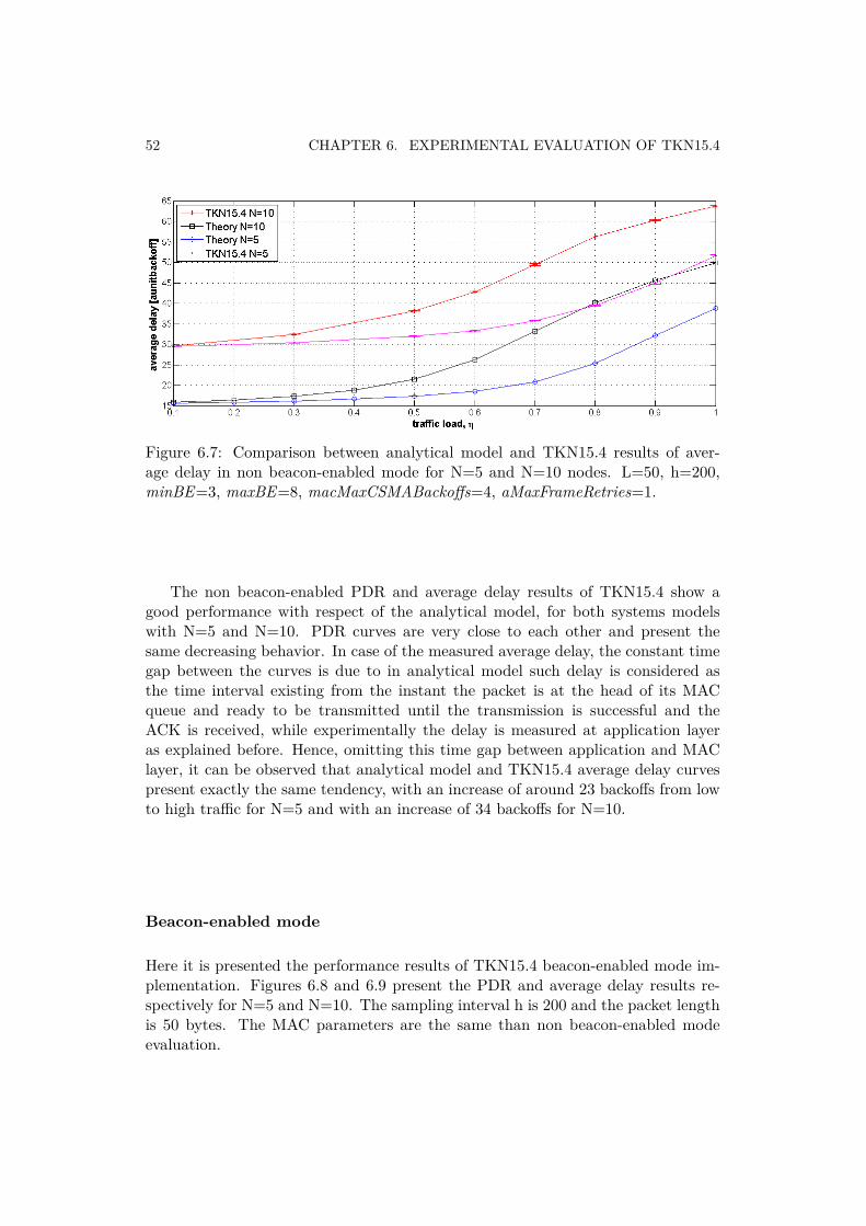
52 CHAPTER 6. EXPERIMENTAL EVALUATION OF TKN15.4
Figure 6.7: Comparison between analytical model and TKN15.4 results of aver-age delay in non beacon-enabled mode for N=5 and N=10 nodes. L=50, h=200,minBE=3, maxBE=8, macMaxCSMABackoffs=4, aMaxFrameRetries=1.
The non beacon-enabled PDR and average delay results of TKN15.4 show agood performance with respect of the analytical model, for both systems modelswith N=5 and N=10. PDR curves are very close to each other and present thesame decreasing behavior. In case of the measured average delay, the constant timegap between the curves is due to in analytical model such delay is considered asthe time interval existing from the instant the packet is at the head of its MACqueue and ready to be transmitted until the transmission is successful and theACK is received, while experimentally the delay is measured at application layeras explained before. Hence, omitting this time gap between application and MAClayer, it can be observed that analytical model and TKN15.4 average delay curvespresent exactly the same tendency, with an increase of around 23 backoffs from lowto high traffic for N=5 and with an increase of 34 backoffs for N=10.
Beacon-enabled mode
Here it is presented the performance results of TKN15.4 beacon-enabled mode im-plementation. Figures 6.8 and 6.9 present the PDR and average delay results re-spectively for N=5 and N=10. The sampling interval h is 200 and the packet lengthis 50 bytes. The MAC parameters are the same than non beacon-enabled modeevaluation.
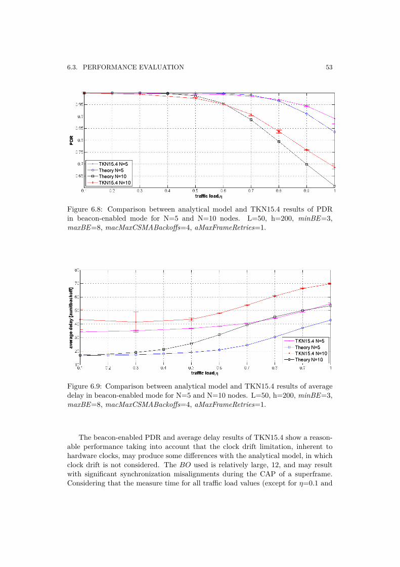
6.3. PERFORMANCE EVALUATION 53
Figure 6.8: Comparison between analytical model and TKN15.4 results of PDRin beacon-enabled mode for N=5 and N=10 nodes. L=50, h=200, minBE=3,maxBE=8, macMaxCSMABackoffs=4, aMaxFrameRetries=1.
Figure 6.9: Comparison between analytical model and TKN15.4 results of averagedelay in beacon-enabled mode for N=5 and N=10 nodes. L=50, h=200, minBE=3,maxBE=8, macMaxCSMABackoffs=4, aMaxFrameRetries=1.
The beacon-enabled PDR and average delay results of TKN15.4 show a reason-able performance taking into account that the clock drift limitation, inherent tohardware clocks, may produce some differences with the analytical model, in whichclock drift is not considered. The BO used is relatively large, 12, and may resultwith significant synchronization misalignments during the CAP of a superframe.Considering that the measure time for all traffic load values (except for η=0.1 and
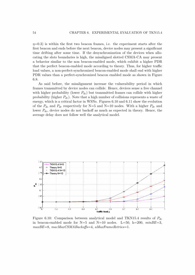
54 CHAPTER 6. EXPERIMENTAL EVALUATION OF TKN15.4
η=0.3) is within the first two beacon frames, i.e. the experiment starts after thefirst beacon and ends before the next beacon, device nodes may present a significanttime drifting after some time. If the desynchronization of the devices when allo-cating the slots boundaries is high, the misaligned slotted CSMA-CA may presenta behavior similar to the non beacon-enabled mode, which exhibit a higher PDRthat the perfect beacon-enabled mode according to theory. Thus, for higher trafficload values, a non-perfect-synchronized beacon-enabled mode shall end with higherPDR values than a perfect-synchronized beacon enabled mode as shown in Figure6.8.
As said before, the misalignment increase the vulnerability period in whichframes transmitted by device nodes can collide. Hence, devices sense a free channelwith higher probability (lower Pdc) but transmitted frames can collide with higherprobability (higher Pdr). Note that a high number of collisions represents a waste ofenergy, which is a critical factor in WSNs. Figures 6.10 and 6.11 show the evolutionof the Pdc and Pdr respectively for N=5 and N=10 nodes. With a higher Pdr andlower Pdc, device nodes do not backoff as much as expected in theory. Hence, theaverage delay does not follow well the analytical model.
Figure 6.10: Comparison between analytical model and TKN15.4 results of Pdc
in beacon-enabled mode for N=5 and N=10 nodes. L=50, h=200, minBE=3,maxBE=8, macMaxCSMABackoffs=4, aMaxFrameRetries=1.
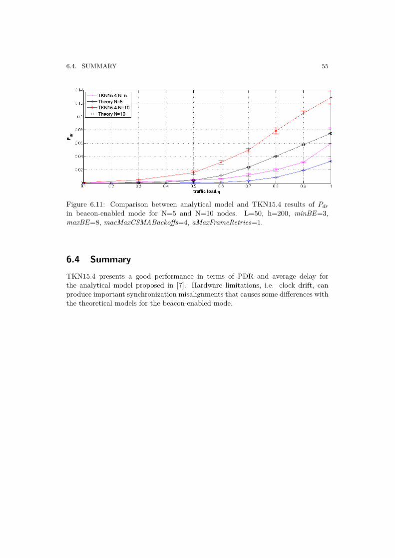
6.4. SUMMARY 55
Figure 6.11: Comparison between analytical model and TKN15.4 results of Pdr
in beacon-enabled mode for N=5 and N=10 nodes. L=50, h=200, minBE=3,maxBE=8, macMaxCSMABackoffs=4, aMaxFrameRetries=1.
6.4 SummaryTKN15.4 presents a good performance in terms of PDR and average delay forthe analytical model proposed in [7]. Hardware limitations, i.e. clock drift, canproduce important synchronization misalignments that causes some differences withthe theoretical models for the beacon-enabled mode.

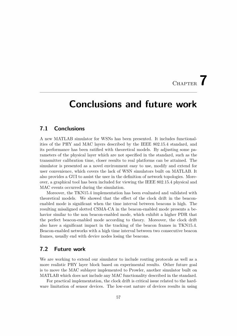
Chapter 7Conclusions and future work
7.1 ConclusionsA new MATLAB simulator for WSNs has been presented. It includes functional-ities of the PHY and MAC layers described by the IEEE 802.15.4 standard, andits performance has been ratified with theoretical models. By adjusting some pa-rameters of the physical layer which are not specified in the standard, such as thetransmitter calibration time, closer results to real platforms can be attained. Thesimulator is presented as a novel environment easy to use, modify and extend foruser convenience, which covers the lack of WSN simulators built on MATLAB. Italso provides a GUI to assist the user in the definition of network topologies. More-over, a graphical tool has been included for viewing the IEEE 802.15.4 physical andMAC events occurred during the simulation.
Moreover, the TKN15.4 implementation has been evaluated and validated withtheoretical models. We showed that the effect of the clock drift in the beacon-enabled mode is significant when the time interval between beacons is high. Theresulting misaligned slotted CSMA-CA in the beacon-enabled mode presents a be-havior similar to the non beacon-enabled mode, which exhibit a higher PDR thatthe perfect beacon-enabled mode according to theory. Moreover, the clock driftalso have a significant impact in the tracking of the beacon frames in TKN15.4.Beacon-enabled networks with a high time interval between two consecutive beaconframes, usually end with device nodes losing the beacons.
7.2 Future workWe are working to extend our simulator to include routing protocols as well as amore realistic PHY layer block based on experimental results. Other future goalis to move the MAC sublayer implemented to Prowler, another simulator built onMATLAB which does not include any MAC functionality described in the standard.
For practical implementation, the clock drift is critical issue related to the hard-ware limitation of sensor devices. The low-cost nature of devices results in using
57
58 CHAPTER 7. CONCLUSIONS AND FUTURE WORK
clocks with low accuracy with a relatively high margin of error. The time as wellas other environmental conditions such as temperature or pressure also influence inthe losing of accuracy of the clocks resulting in significant time deviations. Further-more, the high energy cost that may have some synchronization protocols with extraoverhead added, can not be assumed in WSNs. In case of the IEEE 802.15.4, thesynchronism in the beacon-enabled mode can be controlled with the beacon intervaltime, dependent on the application. Moreover, the standard specifies the use of un-slotted CSMA-CA when the beacon frame can not be tracked. This is not allowedin TKN15.4 because of its component-based nature in which the beacon-enabledor the non beacon-enabled mode is selected at compile time, thus not allowing toswitch from one to another at runtime. However, it would be possible to have twodifferent modes dynamically if enough memory of a device is available
Bibliography
[1] UC Berkeley. Tinyos community forum. http://www.tinyos.net.
[2] A. Wheeler. Commercial applications of wireless sensor networks using zigbee.Communications Magazine, IEEE, 45(4):70 –77, 2007.
[3] A. Alemdar and M. Ibnkahla. Wireless sensor networks: Applications andchallenges. In Signal Processing and Its Applications, 2007. ISSPA 2007. 9thInternational Symposium on, pages 1 –6, 2007.
[4] V.C. Gungor, Bin Lu, and G.P. Hancke. Opportunities and challenges of wire-less sensor networks in smart grid. Industrial Electronics, IEEE Transactionson, 57(10):3557 –3564, 2010.
[5] Pangun Park. Protocol design for control applications using wireless sensornetworks, 2009.
[6] Matlab- language of technical computing.http://www.mathworks.com/products/matiab/.
[7] C. Fischione P. Park and K. H. Johansson. Performance analysis of the ieee802.15.4 hybrid medium access control protocol. Technical report, KTH, 2010.
[8] IEEE std 802.15.4-2996, september, part 15.4: Wireless medium access control(MAC) and physical layer (PHY) specifications for low-rate wireless personalarea networks (WPANs), September 2006.
[9] HART Communication Foundation. Wirelesshart technical data sheet, May2007.
[10] J. Hui D. Culler G. Montenegro, N. Kushalnagar. Transmission of ipv6 packetsover ieee 802.15.4 networks, September 2007.
59
60 BIBLIOGRAPHY
[11] Moteiv Corporation. Tmote sky data sheet.http://www.bandwavetech.com/download/tmote-sky-datasheet.pdf, June2006.
[12] Texas Instrument. CC2420DK Development Kit User Manual.
[13] Chipcon. CC2420 data sheet. http://inst.eecs.berkeley.edu/, June 2004.
[14] Adam Dunkels. Contiki - the operating system for connecting the next billiondevices - the internet of things. http://www.sics.se/contiki/.
[15] Liteos website. http://www.liteos.net/.
[16] Nano-RK website. http://www.nano-rk.org/.
[17] Robert von Behren Matt Welsh Eric Brewer David Gay, Philip Levis and DavidCuller. The nesc language: A holistic approach to networked embedded sys-tems. volume proceedings of programming language design and implementation(PLDI). June 2003.
[18] Aitor Hernandez. Wireless process control using ieee 802.15.4 protocol. Mas-ter’s thesis, KTH Electrical Engineering, 2010.
[19] Jan-Hinrich Hauer. Tkn15.4: An ieee 802.15.4 mac implementation for tinyos2. Technical report, Technical University Berlin, 2009.
[20] The network simulator ns-2. http://www.isi.edulnsnamlns/.
[21] OMNET++ discrete event simulator. http://www.omnetpp.org/.
[22] The OPNET simulator. http://www.opnet.com/.
[23] A. Savvides S. Park and M. B. Srivastava. Sensorsim: A simulation frame-work for sensor networks. in Proc. ACM International Workshop on Modeling,Analysis and Simulation of Wireless and Mobile Systems, 2000.
[24] Castalia - a simulator for wsns. http://castalia.npc.nicta.com.aul.
[25] Prowler: Probabilistic wireless network simulator.http://www.isis.vanderbilt.edulprojects/nestiprowler.
[26] Jprowler: Java-based probablistic wireless network simulator. http://w3.isis.vanderbilt.edu/proj ects/nestijprowler/.
[27] Truetime: Simulation of networked and embedded control systems.http://www3.control.lth.se/truetime/.
[28] Thomas W. Carley. Sidh: A wireless sensor network simulator. Technicalreport, 2004.
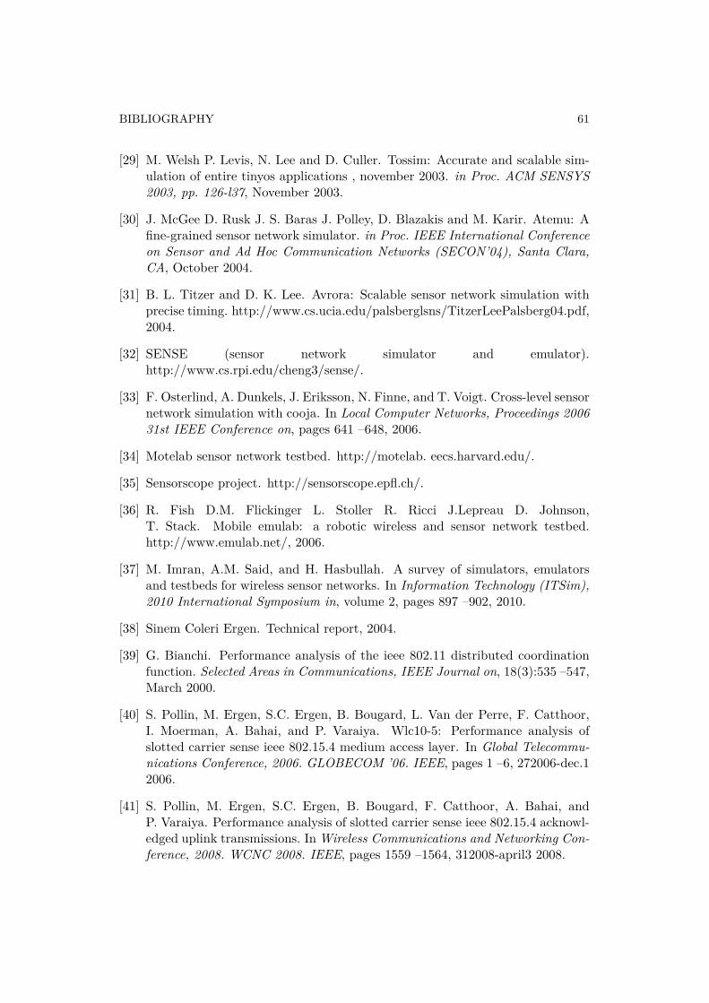
BIBLIOGRAPHY 61
[29] M. Welsh P. Levis, N. Lee and D. Culler. Tossim: Accurate and scalable sim-ulation of entire tinyos applications , november 2003. in Proc. ACM SENSYS2003, pp. 126-l37, November 2003.
[30] J. McGee D. Rusk J. S. Baras J. Polley, D. Blazakis and M. Karir. Atemu: Afine-grained sensor network simulator. in Proc. IEEE International Conferenceon Sensor and Ad Hoc Communication Networks (SECON’04), Santa Clara,CA, October 2004.
[31] B. L. Titzer and D. K. Lee. Avrora: Scalable sensor network simulation withprecise timing. http://www.cs.ucia.edu/palsberglsns/TitzerLeePalsberg04.pdf,2004.
[32] SENSE (sensor network simulator and emulator).http://www.cs.rpi.edu/cheng3/sense/.
[33] F. Osterlind, A. Dunkels, J. Eriksson, N. Finne, and T. Voigt. Cross-level sensornetwork simulation with cooja. In Local Computer Networks, Proceedings 200631st IEEE Conference on, pages 641 –648, 2006.
[34] Motelab sensor network testbed. http://motelab. eecs.harvard.edu/.
[35] Sensorscope project. http://sensorscope.epfl.ch/.
[36] R. Fish D.M. Flickinger L. Stoller R. Ricci J.Lepreau D. Johnson,T. Stack. Mobile emulab: a robotic wireless and sensor network testbed.http://www.emulab.net/, 2006.
[37] M. Imran, A.M. Said, and H. Hasbullah. A survey of simulators, emulatorsand testbeds for wireless sensor networks. In Information Technology (ITSim),2010 International Symposium in, volume 2, pages 897 –902, 2010.
[38] Sinem Coleri Ergen. Technical report, 2004.
[39] G. Bianchi. Performance analysis of the ieee 802.11 distributed coordinationfunction. Selected Areas in Communications, IEEE Journal on, 18(3):535 –547,March 2000.
[40] S. Pollin, M. Ergen, S.C. Ergen, B. Bougard, L. Van der Perre, F. Catthoor,I. Moerman, A. Bahai, and P. Varaiya. Wlc10-5: Performance analysis ofslotted carrier sense ieee 802.15.4 medium access layer. In Global Telecommu-nications Conference, 2006. GLOBECOM ’06. IEEE, pages 1 –6, 272006-dec.12006.
[41] S. Pollin, M. Ergen, S.C. Ergen, B. Bougard, F. Catthoor, A. Bahai, andP. Varaiya. Performance analysis of slotted carrier sense ieee 802.15.4 acknowl-edged uplink transmissions. InWireless Communications and Networking Con-ference, 2008. WCNC 2008. IEEE, pages 1559 –1564, 312008-april3 2008.
62 BIBLIOGRAPHY
[42] Zhifeng Tao, S. Panwar, Daqing Gu, and Jinyun Zhang. Performance analysisand a proposed improvement for the ieee 802.15.4 contention access period.In Wireless Communications and Networking Conference, 2006. WCNC 2006.IEEE, volume 4, pages 1811 –1818, 2006.
[43] J. Misic, S. Shafi, and V.B. Misic. Performance of a beacon enabled ieee802.15.4 cluster with downlink and uplink traffic. Parallel and DistributedSystems, IEEE Transactions on, 17(4):361 – 376, 2006.
[44] C.Y. Jung, H.Y. Hwang, D.K. Sung, and G.U. Hwang. Enhanced markov chainmodel and throughput analysis of the slotted csma/ca for ieee 802.15.4 underunsaturated traffic conditions. Vehicular Technology, IEEE Transactions on,58(1):473 –478, 2009.
[45] P. Sucha, M. Kutil, M. Sojka, and Z. Hanzalek. Torsche scheduling toolbox formatlab. In Computer Aided Control System Design, 2006 IEEE InternationalConference on Control Applications, 2006 IEEE International Symposium onIntelligent Control, 2006 IEEE, pages 1181 –1186, 2006.
[46] Ricardo Severino Jasper Büsch Marco Tiloca Stefano Tennina Jan-Hinrich Hauer, Roberta Daidone. An open-source ieee 802.15.4 mac implemen-tation for tinyos 2.1. In European Conference on Wireless Sensor Networks,2011.