implementation of systemverilog and uvm training
TRANSCRIPT

ARTO OINONENIMPLEMENTATION OF SYSTEMVERILOG AND UVM TRAINING
Master of Science Thesis
Examiners:Professor Timo D. Hämäläinen andDoctor Teemu LaukkarinenExaminer and topic approved by theCouncil of the Faculty of Computingand Electrical Engineeringon 9th December 2015

i
ABSTRACT
ARTO OINONEN: Implementation of SystemVerilog and UVM TrainingTampere University of TechnologyMaster of Science Thesis, 72 pagesJanuary 2017Master’s Degree Programme in Electrical EngineeringMajor: Embedded SystemsExaminer: Prof. Timo D. Hämäläinen, Dr. Teemu Laukkarinen
Keywords: SystemVerilog, UVM, verification, education
Integrated circuits have become more complex every year and their verification has be-come more time-consuming. Therefore, effective education of new verification engineersis important for industry. This thesis covers planning of an efficient exercise package foreducation of verification engineers. The exercises cover key principles of SystemVeriloglanguage and Universal Verification Methodology (UVM). The object of the exercisepackage is that a person with programming experience but no previous experience ofsystem design or verification should be able to digest the most important concepts in fivetraining days and be able to perform verification tasks using UVM after the training.
The planned exercise package was divided into four exercises on SystemVerilog languageand seven exercises on UVM, which cover the methods the designer can use to aid inverification process and the basic principles of UVM methodology. The exercises wereimplemented as independent work so that the assistant was present to help solving prob-lems and to answer questions. The planning of the exercises adapted to the needs of theparticipants on different levels so that every student was able to learn the most importantconcepts and additional more advanced tasks were provided for faster students. The ad-vanced tasks did not introduce new crucial concepts, but deepened the understanding ofthe concepts used in the mandatory exercises.
The exercises were used as a part of digital design and verification education, where theparticipants had a programming background. The completion of learning objectives wasmetered by a time usage survey and a feedback form. Based on the results the learningobjectives were fulfilled and every student was able to comprehend the concepts. Thestudents were contented with the content and the structure of the exercises.
ii
TIIVISTELMÄ
ARTO OINONEN: SystemVerilog- ja UVM-harjoitusten toteutusTampereen teknillinen yliopistoDiplomityö, 72 sivuaTammikuu 2017Sähkötekniikan diplomi-insinöörin tutkinto-ohjelmaPääaine: Sulautetut järjestelmätTarkastajat: Prof. Timo D. Hämäläinen, TkT Teemu Laukkarinen
Avainsanat: SystemVerilog, UVM, varmennus, verifiointi, koulutus
Integroitujen piirien koko on kasvanut jatkuvasti ja suunnittelun varmennukseen käytettyaika on entistä suurempi osa projektin kokonaiskestoa. Siksi on tärkeää kouluttaa uusiavarmennuksen osaajia mahdollisimman tehokkaasti yritysten tarpeisiin. Tämä diplomityökuvaa tehokkaan varmennusharjoituspaketin suunnitteluprosessia. Harjoituksissa käy-dään läpi SystemVerilog-kielen sekä UVM-varmennusmenetelmän keskeisimmät omi-naisuudet. Harjoitusten tavoitteena on, että työntekijä, jolla on ohjelmointitaustaa muttaei aiempaa suunnittelu- tai varmennuskokemusta, pystyy sisäistämään tärkeimmän sisäl-lön viiden koulutuspäivän aikana ja työskentelemään koulutuksen jälkeen varmennusteh-tävissä käyttäen UVM-menetelmää.
Harjoituspaketti on jaettu neljään SystemVerilog- ja seitsemään UVM-harjoitukseen,joissa esitellään käytännöt joita suunnittelija voi tehdä varmennuksen kannalta sekäUVM-menetelmän perustoiminnot. Harjoitukset suunniteltiin itsenäisesti tehtäväksi niinettä assistentti on paikalla avustamassa ongelmatilanteissa sekä vastaamassa kysymyk-siin. Harjoitukset mukailevat opiskelijoiden erilaisia lähtötasoja niin että jokainen ehtiioppia perusasiat mutta nopeimmille opiskelijoille on syventäviä lisätehtäviä. Lisätehtäväteivät esittele uusia tärkeitä asioita vaan syventävät perusharjoituksissa hankittua tietoa.
Harjoituksia käytettiin osana Digitaalisuunnittelu ja varmennus –opintokokonaisuutta,minkä osallistujilla oli enimmäkseen ohjelmointitausta. Oppimistavoitteiden saavutta-mista tarkkailtiin ajankäyttö- ja palautelomakkeiden avulla. Tuloksien perusteella oppi-mistavoitteet saavutettiin hyvin ja koulutukseen osallistujat olivat tyytyväisiä harjoitustensisältöön sekä rakenteeseen.

iii
PREFACE
This Master of Science Thesis was done for the Department of Pervasive Computing atTampere University of Technology as a part of a digital design and verification educationarranged by Edutech during fall 2015. The education team was full of great people andexperts on their fields and I was privileged to be part of it.
The exercise package that was built in this thesis was designed as independent work, butthe UVM exercises were partly based on OVM exercises designed by Ville Yli-Mäyryfor a previous verification course arranged by the Department of Pervasive Computing atTampere University of Technology.
I would like to thank professor Timo D. Hämäläinen, Dr. Teemu Laukkarinen and TaruHakanen for all the support and for giving me this opportunity. I also want to thank VilleYli-Mäyry for the basis of the UVM exercises.
The UVM video lectures on Verification Academy were of invaluable help when learningUVM. I extend special thanks to Tom Fitzpatrick for the video lectures and Dave Richfor active online help on multiple forums.
My deepest gratitude to my family and friends for all the support and for pushing meforward.
Tampere, 22.12.2016
Arto Oinonen

iv
CONTENTS
1. INTRODUCTION ................................................................................................ 11.1 Background of verification methodologies .................................................. 21.2 Motivation, methods, and scope of thesis .................................................... 41.3 Outline of thesis .......................................................................................... 6
2. SYSTEMVERILOG ............................................................................................. 72.1 SystemVerilog for design............................................................................ 72.2 SystemVerilog for verification .................................................................. 12
3. UNIVERSAL VERIFICATION METHODOLOGY (UVM) .............................. 163.1 UVM building blocks ............................................................................... 17
3.1.1 Objects and components .............................................................. 183.1.2 Macros and methods ................................................................... 21
3.2 UVM architecture ..................................................................................... 243.2.1 UVM Environment ..................................................................... 243.2.2 UVM Tests ................................................................................. 26
4. REQUIREMENTS AND METHODS FOR THE TRAINING ............................. 284.1 Requirements and student background ...................................................... 284.2 Tools used in the exercises ........................................................................ 294.3 Structure of exercises ................................................................................ 30
5. SYSTEMVERILOG EXERCISES ...................................................................... 335.1 Learning objectives ................................................................................... 335.2 Structure ................................................................................................... 34
5.2.1 Exercise 1: Introduction to SystemVerilog .................................. 355.2.2 Exercise 2: Decrypter module ..................................................... 375.2.3 Exercise 3: Assertions and testbenches ........................................ 395.2.4 Exercise 4: Bus connectivity ....................................................... 41
6. UVM EXERCISES ............................................................................................. 436.1 Learning objectives ................................................................................... 436.2 Procedures and UVM concepts used in the exercises ................................ 446.3 Structure ................................................................................................... 45
6.3.1 Exercise 1: Introduction to UVM ................................................ 476.3.2 Exercise 2: Creating classes ........................................................ 496.3.3 Exercise 3: Subscribers and analysis ports ................................... 536.3.4 Exercise 4: Automatic checking and randomized input ................ 576.3.5 Exercise 5: Verifying FIFO blocks .............................................. 616.3.6 Exercise 6: Verifying the decrypter ............................................. 616.3.7 Exercise 7: Integration level testbench ........................................ 63
7. TRAINING SESSIONS AND RESULTS ........................................................... 657.1 Learning outcomes ................................................................................... 657.2 Student feedback ...................................................................................... 677.3 Problems faced ......................................................................................... 69

v
8. CONCLUSIONS ................................................................................................. 72

vi
LIST OF FIGURES
Figure 1. Design and verification gaps. ................................................................. 1Figure 2. ASIC Project time spent on verification, as found in the Wilson
Research Group study in 2014. [12] ....................................................... 2Figure 3. The evolution of verification methodologies. [8] ..................................... 3Figure 4. The ASIC design size trends in 2014. [12] .............................................. 4Figure 5. ASIC/IC testbench methodology adoption trends. [11] ......................... 17Figure 6. UVM base class hierarchy. [3] ............................................................. 19Figure 7. UVM component class hierarchy. [3] ................................................... 19Figure 8. Port – export – implementation connection. [3] .................................... 20Figure 9. UVM Phases. [5].................................................................................. 22Figure 10. A complete block level testbench. [5].................................................... 24Figure 11. The UVM exercise index page. ............................................................. 30Figure 12. An example of an exercise page. 1 describes a bullet with the
concrete task and 2 is body text containing the motivation for thetask. 3 is an example of a code block. ................................................... 31
Figure 13. An information block example. ............................................................. 32Figure 14. The complete encrypt-decrypt system. [20] ........................................... 37Figure 15. A state diagram for the decrypter module. ............................................ 38Figure 16. Block diagram of the testbench for the decrypter module. ..................... 40Figure 17. AXI wrapper. ........................................................................................ 41Figure 18. Testbench folder layout. ....................................................................... 45Figure 19. The final testbench after finishing exercise 5. ....................................... 46Figure 20. The base testbench delivered to the student. ......................................... 48Figure 21. Testbench with the monitor attached. ................................................... 50Figure 22. Delivering DUT interface to monitor .................................................... 51Figure 23. Coverage collector added to the testbench............................................ 54Figure 24. Scoreboard added to the testbench. ...................................................... 58Figure 25. The final UVM testbench. ..................................................................... 60Figure 26. The integration level testbench. [18] .................................................... 63Figure 27. Completion of each exercise. ................................................................ 66Figure 28. Time usage in each UVM exercise. ....................................................... 66

vii
LIST OF SYMBOLS AND ABBREVIATIONS
AMBA Advanced Microcontroller Bus ArchitectureAXI Advanced Extensible InterfaceASIC Application Specific Integrated CircuitDUT Design under testEDA Electronic design automationeRM e Reference ManualFIFO First in, first outIC Integrated CircuitIP Intellectual propertyOVM Open Verification MethodologyPCI Peripheral Component InterconnectRAL Register Abstraction LayerRVM Reference Verification MethodologyUVM Universal Verification MethodologyUSB Universal Serial BusVHDL Very High Speed IC Hardware Description LanguageVMM Verification Methodology ManualXOR Exclusive or operation

1
1. INTRODUCTION
The transistor revolution has brought complex digital systems as an integral part of eve-ryday life where the applications of integrated circuits (ICs) vary from simple toys tomainframe datacenters. As the Moore’s law has dictated, the number of transistors inintegrated circuits has doubled approximately every two years, which has consequentlyincreased the complexity of ICs. The increase in design complexity creates a burden ondesign and verification engineers so that the design effort needed for a project exceedsmaximum productivity. A rendition of so-called design and verification gaps that portraythe difference between effort and productivity is shown in Figure 1. The feature size thatfollows the Moore’s law depicts the design effort needed for completing a complex pro-ject.
Figure 1. Design and verification gaps.
Increasing design reuse has decreased the design gap, but reuse in verification has notbeen as mature, so the trend is that the growth of the design gap will slow down but theverification gap will continue growing, as found in study done by Wilson Research Groupin 2014 [12]. They found out that the percentage of application specific integrated circuit(ASIC) project time spent in verification has been growing rapidly as shown in Figure 2.Notably, the amount of projects where verification covers over 70% of the project timehas been growing every time the study has been made.
Complexity
Time
Designgap
Verificationgap

2
Figure 2. ASIC project time spent on verification, as found in the Wilson ResearchGroup study in 2014. [12]
1.1 Background of verification methodologies
Verification is a process that examines if all the aspects of the design follow the specifi-cation correctly [9]. Verification can be functional or formal. The difference is that func-tional verification runs a simulation of the design under test (DUT) in a testbench thatfeeds the design test input and checks its output, when formal verification proves thecorrect functionality with a mathematical model. Validation is another procedure in de-sign functionality checking. Validation is used to ensure that the design meets the func-tional requirements and the needs of the customer.
Traditionally systems were first designed using hardware description languages such asVHDL and Verilog and then functionally verified using testbenches written in the samelanguages [19]. However, the hardware description languages were not designed to beeffective in verification purposes and the system complexity quickly outgrew the verifi-cation capabilities of the language. Writing complex tests for large systems would bemore effective with languages that function on higher levels of abstraction.
Specific verification languages, such as e and Vera, were created as an answer to theproblem [10]. They were closer to traditional high-level programming languages and in-troduced for example object-oriented properties, complex assertions, coverage meteringand constrained randomization to aid verification engineers. The problems with these lan-guages were that learning a completely new language for verification meant a lot of un-productive work and the large set of languages might have prevented design engineers
0 %
5 %
10 %
15 %
20 %
25 %
30 %
1% -20%
21% -30%
31% -40%
41% -50%
51% -60%
61% -70%
71% -80%
81% -100%
Proj
ects
Percentage of project time spent in verification
2007: Average 46%
2012: Average 56%
2014: Average 57%

3
from doing also verification. In addition, some of the languages were tied to specific soft-ware tools produced by the developer of the language and were not supported in othertools. The worst-case situation was that a company had to use multiple verification lan-guages with accompanying tools to verify different parts of the design.
Verification languages are powerful and versatile tools but writing verification environ-ments from scratch every time for new tests is not effective. Some parts of the code inexisting systems can be reused, but there are no standard procedures built into the lan-guages and therefore components written by different verification engineers may not becompatible. Companies can have internal guidelines, but the procedures used in one com-pany may not be compatible with the guidelines of the subcontractor or the verificationIP vendor. To ease the reuse and to provide a common system for testbench design, veri-fication methodologies have been introduced. Simply put the verification methodologiesare guidelines of functional partitioning of the testbench so that most of the componentscan be reused in different test configurations. In addition, the methodologies could pro-vide methods, macros and control of the simulation procedure.
All the three design tool market leaders - Cadence, Synopsys and Mentor Graphics - hadmultiple competing methodologies written in different languages [8]. A hierarchy of theevolution of some of the methodologies is shown in Figure 3. E Reuse Methodology wasfirst introduced in 2002 and it was followed by competing OpenVera Reference Verifi-cation Methodology (RVM) developed by Synopsys and Advanced Verification Method-ology (AVM) by Mentor Graphics. New methodologies were later introduced that werebuilt on the previous methodologies.
Figure 3. The evolution of verification methodologies. [8]
The diversity in languages, methodologies and tools created a need for universal industrystandards. Accellera Systems Initiative was created as a consortium of EDA companies

4
for the task. The basis for a new standard language was a combination of Verilog hard-ware description language and OpenVera that was donated to Accellera. The result wasSystemVerilog that was standardized in 2005 as an extension to Verilog [19]. A plan fora new standard methodology was introduced by Accellera in 2009 with a proposed nameUniversal Verification Methodology (UVM) [6]. It was built on the SystemVerilog lan-guage combining the previous methodologies OVM and VMM. SystemVerilog and UVMhave since evolved and their usage in the industry has been constantly growing [11].
1.2 Motivation, methods, and scope of thesis
The trend in design sizes were observed in the Wilson Research Group study in 2014 tofollow the Moore’s law, as shown in the Figure 4 [12]. The majority of design sizes in2014 were still on the same scales as in 2007, but the amount of designs on the highestborder of the spectrum has been growing at the same time as the border has been movedto cover designs that are more complex.
Figure 4. The ASIC design size trends in 2014. [12]
As the design sizes trend to increase, efficient usage of verification methodologies wouldhave a strong impact on verification productivity and shorten the time to market. Theintegration of verification methodologies as a valuable part of design projects requireseducation of verification engineers who master the concepts, because the methodologiesare complex collections of precisely defined rules and principles that would take a longtime to adopt from large reference manuals. An education that follows the standardizedguidelines would ensure that the work done by different verification engineers is compat-ible.

5
Especially the companies starting to adopt UVM, but also those that have already inte-grated UVM and orientate new verification engineers, would benefit from a short andeffective training. A specifically tailored education would cover all the target areas thecompany finds the most important and produce quickly new verification engineers thatare ready to start implementing verification environments. An efficient education shouldalso include lots of hand-on training that simulates the real verification tasks so the stu-dents can apply their knowledge to real-world problems and learn new principles at thesame time.
This thesis presents the planning and implementation of an exercise package that can beused in an efficient verification education. The objective is to create an efficient exercisepackage that introduces the key concepts of SystemVerilog language and Universal Ver-ification Methodology on a compact schedule. After finishing the exercises, a studentwith no previous verification or design background should understand the reasons for theamount of work done on verification and validation and be able to perform verificationwork using the current standard language and methodology.
The exercises were made as a part of a specifically tailored digital design and verificationeducation that was ordered by a company. The aim of the education was to introduceemployees with a programming background into hardware design and verification con-cepts and reeducate them to perform verification work using UVM.
The requirements for the verification module made by the customer dictated that the par-ticipants should understand the basic principles of verification, master the key mecha-nisms and syntax of SystemVerilog in the verification perspective and be able to use theUVM class library so that he can produce a working test environment.
The underlying theory of SystemVerilog and UVM is introduced on a level that would berequired for understanding the scope of the exercises. The planned contents of each exer-cise is portrayed precisely, so that this thesis would help new assistants responsible forthe same exercises to understand the concepts and the reasons for the used methods. So-lutions for the exercises are not provided, so this thesis alone would not be sufficient fororientation material.
The planned exercise projects are tested by implementing them in the classroom as partof the education module. The metered results are the time usage in each exercise and afeedback form that was returned by the students after the education. Another interestingmeter would be to follow if the participants in the education were placed later to performverification tasks in the company and their later opinions on how the education preparedthem for the tasks. This could have been monitored with a survey one year later after theeducation, but such a survey has not been done.
Pedagogy would be an important factor in education design to ensure that the selectedteaching methods would best serve the learning process. Pedagogy was left out of the

6
scope of this thesis, but the planning of teaching methods follows subjective experiencesof well-designed exercises during previous study work.
1.3 Outline of thesis
The thesis is divided into seven parts. Chapter 2 introduces the SystemVerilog languageconsidering both the design and verification perspectives of the language. The purpose ofthe chapter is to provide an overview of the basics of the language and to explain thedetails of the concepts that are used in the following chapters. The most important con-cepts that would be emphasized in the exercises are outlined. Chapter 3 outlines the basicprinciples of Universal Verification Methodology on a level that was needed in this thesisand drafts a plan, how the principles are introduced to the student when planning theexercises. Small examples of advanced concepts are also introduced to widen the per-spective and to introduce the possibilities that integrating UVM in verification processoffers.
Chapter 4 explains the preliminary requirements for the training and introduces the se-lected teaching methods. It also provides information of the practical arrangements, suchas the development environment and the tools used in the training. Chapters 5 and 6 ex-plain the contents of the exercise instructions. Chapter 5 describes the SystemVerilogexercises and chapter 6 concentrates on the UVM portion of the training. A large numberof code examples in these chapters are provided to offer a deeper understanding of thetheory in Chapters 2 and 3.
Chapter 7 reviews the results of the training. The completion of the learning objectiveswas monitored with a time usage survey and a feedback form that are analyzed in thechapter. The chapter also explains the problems that were faced during the exercise ses-sions and offers improvement suggestions if a similar education is arranged later. Finally,Chapter 8 concludes this thesis.

7
2. SYSTEMVERILOG
SystemVerilog is a unified hardware description, specification and verification languagethat was first described in the standard IEEE 1800-2005 and most recently updated in2012. It started as a set of extensions for the Verilog design language described in stand-ard IEEE 1364-2005, but the two standards were merged into a single language in 2009[15, 16]. The purpose of the original SystemVerilog extensions was to provide verifica-tion engineers with tools on higher abstraction level to improve productivity, readabilityand reusability. They also provided design specification methods such as new data types,packages, extended port declarations and interfaces [13, 14].
Because the two standard have been merged, this thesis does not differentiate the Veriloglanguage from the SystemVerilog extensions, but describes the design and verificationproperties of the unified language following the IEEE 1800-2009 standard. Therefore, notall the code examples are fully compatible with the older Verilog standard. There are afew common Verilog design principles that are still used but upon which SystemVeriloghas made improvements, so they have been considered to be worth explaining.
Understanding the basic SystemVerilog principles is mandatory for completing the exer-cises in the education module. This chapter introduces extracts from the language stand-ard that explain the basic concepts that are used in the SystemVerilog and UVM exercises.The most important parts of the basic concepts are selected to form the learning objectivesfor the education.
2.1 SystemVerilog for design
The focus of the training module is on verification, but before inspecting the high-levelverification properties of the SystemVerilog language it is beneficial to know the design-oriented side of the language, because the high-level verification language was originallyan extension to the Verilog hardware description language. A verification engineer willalso encounter designs to be tested written in SystemVerilog and knowing the designprinciples of the language will enable him to find and correct the bugs in the design. Thissection introduces the most basic design concepts of SystemVerilog that would be usedin the SystemVerilog exercises with code examples.
The SystemVerilog design hierarchy consists of modules that are the basic buildingblocks [15]. Modules represent design units that have input and output ports and logiccombining them. Modules communicate with each other usually through the input andoutput ports. Program 1 describes the declaration of a simple module that performs abitwise and operation for signals a and b.

8
module simple_and (input wire a, b, output y);assign y = a & b;
endmodule: simple_and
Program 1. Module declaration.
The module declaration in the Program 1 is started with the module header and endedwith keyword endmodule. The module header describes the ports and gives the module aspecific name to differentiate it from other modules. The input and output port declara-tions in the header include the port directions and data types. If the data type is omitted,as is the case for the output signal y, it will be implicitly declared by the compiler. Anassign primitive is used to set the output value and to form the logic between the ports.
The module header in Program 1 where the port directions are listed follows the ANSItype declaration of SystemVerilog. The ANSI type declaration is not supported in theVerilog language and the traditional way is to declare only the data types in the headerand the directions on the first lines after the declaration. The ANSI method is advised tobe used, because it reduces unwanted repetition.
Modules can be instantiated inside each other to create design hierarchy, as shown inProgram 2. In the example a top-level module, that has no input or output ports itself,creates an instance of the simple_and module that was described in Program 1. Internalvariables in1, in2 and out1 are connected to the ports of the instantiated module.
module top; // module with no portslogic in1, in2; // variable declarationswire out1; // net declaration
// module instance simple_and u1 ( .a(in1), .b(in2), .y(out1));endmodule: top
Program 2. Module instantiation.
Modules were chosen to be an integral part of the learning objectives, as they are the basisfor every SystemVerilog design. The first thing the student should learn in the exercisesshould be to declare a module using the ANSI type declaration but he should know of theexistence of non-ANSI type declaration as well. He should also be able to instantiatemodules to create hierarchical designs.
Procedural statements describe behavioral code, where programming statements, for ex-ample if-else, case or for loop structures, can be used to describe the functionality. Thestatements usually contain a sequential block delimited by keywords begin and end,where the statements are executed sequentially in the given order so that all the statements

9
inside the procedure act syntactically like a single assignment. There are two basic typesof procedures: initial and always. Initial procedures run only once and they are usuallyused for variable initialization. Always procedures describe combinational or sequentiallogic that is run triggered by events in the sensitivity list. The sensitivity list is declaredusing the character @.
SystemVerilog introduces separate always_comb and always_ff procedures that specifi-cally state the designer intention. The benefit of using these new procedures is that thecompiler should generate a warning, if the desired function is not achieved. An al-ways_comb procedure has an inferred sensitivity list so that it is run every time any ofthe signals used in the procedure change. An always_ff procedure always generates se-quential logic and the sensitivity list should contain clock and reset signals. Simple ex-amples of always_comb and always_ff procedures are shown in Program 3. The al-ways_comb procedure describes a 2-to-1 multiplexer. The output signal y is connected tothe a or b input depending on the selection signal sel. The always_ff procedure is set torun on every rising edge of the clock signal when the asynchronous reset is set high andupdate the d input value to q output. On the falling edge of the reset signal, the output isset to 0, where it stays until the reset is set high.
// An always_comb procedure describing combinational logicalways_comb begin // procedural blockif (sel) y = a; // procedural statementelse y = b;
end
// An always_ff procedure describing a D flip-flopalways_ff @(posedge clock iff reset_n == 1 or negedge reset_n) begin q <= reset_n ? d : 0;end
Program 3. Procedure example. [15]
The learning objectives should include procedures and sequential blocks near the begin-ning of the SystemVerilog exercises. Because most of design work uses synchronouslogic, the exercises should concentrate on the always_ff procedure, but also introduceinitial and combinational procedures.
The data types in SystemVerilog are divided to nets and variables. Nets represent physicalconnections and do not store data. Therefore, they cannot be used in procedural state-ments. The most common net type is wire, which is a 4-state type. 4-state types can havevalues ‘1’, ‘0’, ‘X’ or ‘Z’, where ‘X’ represents an unknown logic value and ‘Z’ is a high-impedance state. 2-state data types also exist. They can have only values 0 and 1, but theyare not synthesizable and are meant to be used in simulation to reduce overhead.
Variables can store data and can be written in procedural statements unlike nets. The mostcommon variable type is logic, which is a 4-state type. In Verilog, the basic variable typewas reg, but it has been renamed to logic to avoid confusion, as the name reg can be
10
perceived to imply a hardware register. The reg data type still exists in SystemVerilog,but the use of logic is preferred.
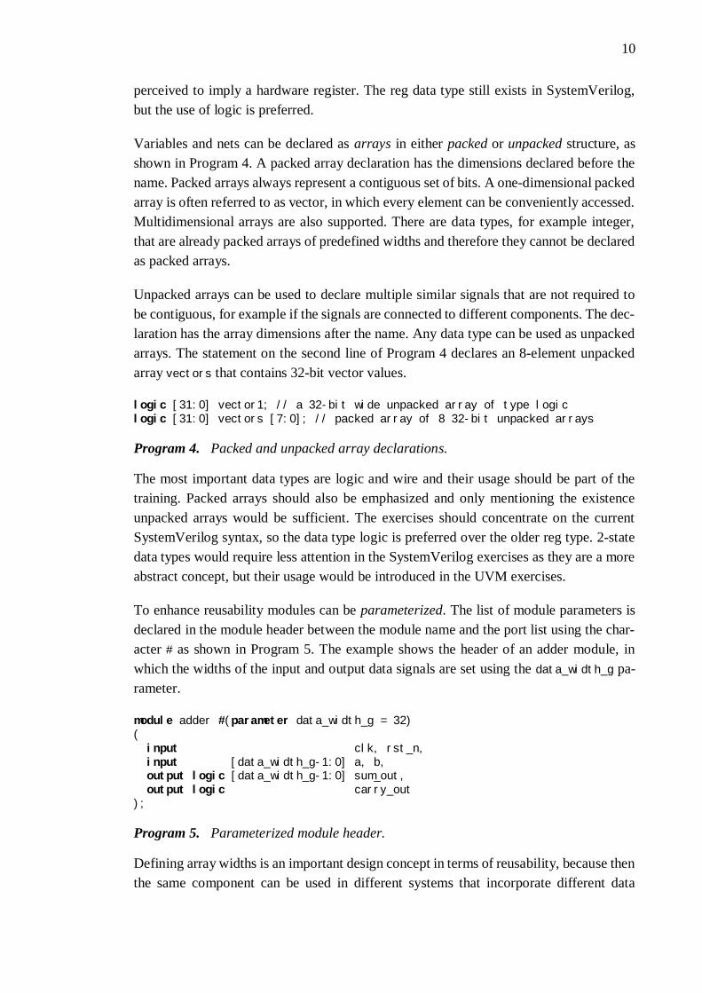
Variables and nets can be declared as arrays in either packed or unpacked structure, asshown in Program 4. A packed array declaration has the dimensions declared before thename. Packed arrays always represent a contiguous set of bits. A one-dimensional packedarray is often referred to as vector, in which every element can be conveniently accessed.Multidimensional arrays are also supported. There are data types, for example integer,that are already packed arrays of predefined widths and therefore they cannot be declaredas packed arrays.
Unpacked arrays can be used to declare multiple similar signals that are not required tobe contiguous, for example if the signals are connected to different components. The dec-laration has the array dimensions after the name. Any data type can be used as unpackedarrays. The statement on the second line of Program 4 declares an 8-element unpackedarray vectors that contains 32-bit vector values.
logic [31:0] vector1; // a 32-bit wide unpacked array of type logiclogic [31:0] vectors [7:0]; // packed array of 8 32-bit unpacked arrays
Program 4. Packed and unpacked array declarations.
The most important data types are logic and wire and their usage should be part of thetraining. Packed arrays should also be emphasized and only mentioning the existenceunpacked arrays would be sufficient. The exercises should concentrate on the currentSystemVerilog syntax, so the data type logic is preferred over the older reg type. 2-statedata types would require less attention in the SystemVerilog exercises as they are a moreabstract concept, but their usage would be introduced in the UVM exercises.
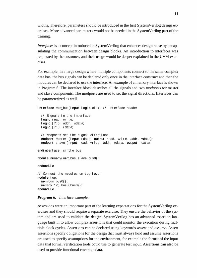
To enhance reusability modules can be parameterized. The list of module parameters isdeclared in the module header between the module name and the port list using the char-acter # as shown in Program 5. The example shows the header of an adder module, inwhich the widths of the input and output data signals are set using the data_width_g pa-rameter.
module adder #(parameter data_width_g = 32)(input clk, rst_n,input [data_width_g-1:0] a, b,output logic [data_width_g-1:0] sum_out,output logic carry_out
);
Program 5. Parameterized module header.
Defining array widths is an important design concept in terms of reusability, because thenthe same component can be used in different systems that incorporate different data
11
widths. Therefore, parameters should be introduced in the first SystemVerilog design ex-ercises. More advanced parameters would not be needed in the SystemVerilog part of thetraining.
Interfaces is a concept introduced in SystemVerilog that enhances design reuse by encap-sulating the communication between design blocks. An introduction to interfaces wasrequested by the customer, and their usage would be deeper explained in the UVM exer-cises.
For example, in a large design where multiple components connect to the same complexdata bus, the bus signals can be declared only once in the interface construct and then themodules can be declared to use the interface. An example of a memory interface is shownin Program 6. The interface block describes all the signals and two modports for masterand slave components. The modports are used to set the signal directions. Interfaces canbe parameterized as well.
interface mem_bus(input logic clk); // Interface header
// Signals in the interfacelogic read, write;logic [7:0] addr, wdata;logic [7:0] rdata;
// Modports set the signal directionsmodport master (input rdata, output read, write, addr, wdata);modport slave (input read, write, addr, wdata, output rdata);
endinterface: simple_bus
module memory(mem_bus.slave bus0); ...endmodule
// Connect the modules on top levelmodule top; mem_bus bus0(); memory 12(.bus0(bus0));endmodule
Program 6. Interface example.
Assertions were an important part of the learning expectations for the SystemVerilog ex-ercises and they should require a separate exercise. They ensure the behavior of the sys-tem and are used to validate the design. SystemVerilog has an advanced assertion lan-guage built in to allow complex assertions that could monitor the execution during mul-tiple clock cycles. Assertions can be declared using keywords assert and assume. Assertassertions specify obligations for the design that must always hold and assume assertionsare used to specify assumptions for the environment, for example the format of the inputdata that formal verification tools could use to generate test input. Assertions can also beused to provide functional coverage data.

12
SystemVerilog assertions can be either immediate or concurrent. Immediate assertionsare checked every time the statement line is run following the simulation event semantics.They are intended to be used in simulation. Concurrent assertions are always active basedon clock semantics and use sampled variable values. They can be used to describe behav-ior that spans over time, for example to check signal values during multiple clock cycles.The concurrent assertions can also be used in formal verification tools in addition toevent-based simulation.
Program 7 introduces an example of an immediate assertion that can be used in simula-tion. The assertion checks on every rising edge of the clock that logical or operation ofsignals req1 and req2 is always true. If the assertion fails, the simulator will print an errormessage including the current simulation time, as specified in the else branch. If the elsecondition is not specified, the default procedure is to use an error print.
time t;
always @(posedge clk) if (state == REQ)
assert (req1 || req2)else begin
t = $time; #5 $error("assert failed at time %0t",t);
end
Program 7. An immediate assertion. [15]
Program 8 shows an example of concurrent assertions. This assertion ensures that everytime the enable_in signal has a rising edge, the signal valid has to be set to 1 after twoclock cycles. The assertion is tied to the rising edge of the clock signal, but disabled if thesystem is in reset. Concurrent assertion can be very complex and used to validate correctsignal behavior over long time.
assert property (@(posedge clk) disable iff(~rst_n)$rose(enable_in) |-> ##2 valid == 1);
Program 8. A concurrent assertion.
2.2 SystemVerilog for verification
A significant difference between Verilog and SystemVerilog is the support for object-oriented programming for verification purposes on a higher abstraction level. The vastlanguage reference is not completely explained in this section, but only the basic object-oriented properties that are needed for understanding the structure of UVM. The learningobjectives for the exercises required that the object-oriented properties should be coveredin the exercises and this section provides an overview of the required concepts. The con-cepts would be introduced to the student in UVM exercises.
13
The object-oriented properties in SystemVerilog follow object-oriented programmingguidelines very closely, so the structure is familiar for designers who have programmingexperience in C++, Java or other object-oriented languages [19]. The main benefit in ob-ject-oriented testbench design is that the designer can declare complex data types andcombine them with routines that use the data. Instead of toggling bits in the DUT directly,those routines can be used to perform even complex transactions without considering thestate of every bit on every clock cycle.
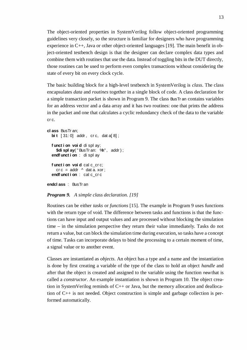
The basic building block for a high-level testbench in SystemVerilog is class. The classencapsulates data and routines together in a single block of code. A class declaration fora simple transaction packet is shown in Program 9. The class BusTran contains variablesfor an address vector and a data array and it has two routines: one that prints the addressin the packet and one that calculates a cyclic redundancy check of the data to the variablecrc.
class BusTran;bit [31:0] addr, crc, data[8];
function void display;$display("BusTran: %h", addr);
endfunction : display
function void calc_crc; crc = addr ^ data.xor;endfunction : calc_crc
endclass : BusTran
Program 9. A simple class declaration. [19]
Routines can be either tasks or functions [15]. The example in Program 9 uses functionswith the return type of void. The difference between tasks and functions is that the func-tions can have input and output values and are processed without blocking the simulationtime – in the simulation perspective they return their value immediately. Tasks do notreturn a value, but can block the simulation time during execution, so tasks have a conceptof time. Tasks can incorporate delays to bind the processing to a certain moment of time,a signal value or to another event.
Classes are instantiated as objects. An object has a type and a name and the instantiationis done by first creating a variable of the type of the class to hold an object handle andafter that the object is created and assigned to the variable using the function new that iscalled a constructor. An example instantiation is shown in Program 10. The object crea-tion in SystemVerilog reminds of C++ or Java, but the memory allocation and dealloca-tion of C++ is not needed. Object construction is simple and garbage collection is per-formed automatically.

14
class Packet;integer command;function new();
command = IDLE;endfunction
endclass
...Packet p; // declare a variable of class Packetp = new; // initialize variable to a new allocated object // of the class Packet
Program 10. Class instantiation. [15]
New classes can be derived from base classes using the extends keyword [15]. The de-clared properties and methods in the base class can be accessed using the keyword super,or overridden by declaring new methods. Program 11 shows an example, where the classLinkedPacket is derived from the Packet class described in Program 10. TheLinkedPacket class is a special form of the class Packet, which introduces a new methodget_next that returns an object of the type LinkedPacket. As the LinkedPacket is extendedfrom the Packet class, every LinkedPacket object is a legal Packet object. A LinkedPacket
object handle can be assigned to a variable of type Packet.
class LinkedPacket extends Packet;
LinkedPacket next;
function LinkedPacket get_next(); get_next = next;endfunction
endclass
Program 11. Class inheritance. [15]
Class declarations in SystemVerilog, including routines and inheritance, will be intro-duced to the student in the UVM exercises and therefore they will not require a separateexercise in the SystemVerilog part of the training. The syntax of SystemVerilog for ver-ification is not emphasized as the motive for any UVM exercises, but it will still be listedas one of the important learning objectives that the student will learn on the side when heis getting familiar with UVM.
SystemVerilog has also introduced new block statements in addition to the sequentialblocks that are delimited by the begin and end keywords [15]. There is also a parallelblock that is delimited by keywords fork and join. All the statements in the block areprocessed concurrently, so the code in Program 12, that sets the value of the variable r
after certain clock cycle delays, finishes 200 clock cycles after entering the block. A sim-ilar sequential block would process the assignments one at the time, so the processingtime would be 500 clock cycles when all the delays are added together. If the executiondoes not have to wait for all the forked statements to finish, additional join keywords

15
join_none and join_any can be used to change the behavior. As functions do not have aconcept of time, the usage of parallel blocks in the functions is limited.
fork#50 r = 'h35;#100 r = 'hE2;#150 r = 'h00;#200 r = 'hF7;
join
Program 12. An example of a parallel block [15].
Parallel blocks are not important for the education because they would not be requiredfor the designs in the exercises. Therefore, they will be omitted from the exercise instruc-tions. Using parallel blocks in a UVM testbench would allow more complex testbenchdesigns, but finding them out is left for the student himself. If the student declares a needfor parallel processing in his testbench, the assistant can hint the usage during exercisesessions.

16
3. UNIVERSAL VERIFICATION METHODOLOGY(UVM)
Unified Verification Methodology (UVM) is a class library written in SystemVerilog. Itis developed and standardized by Accellera, which is a consortium of EDA tool vendorsand users including Synopsys, Mentor Graphics, Cadence, AMD, Intel, ARM and othercompanies [2]. Accellera released a press release in July 2015 where it was announcedthat UVM will be submitted as IEEE standard IEEE 1800.2 and the work is currently inprogress [1].
The purpose of UVM was to combine the principles of several verification methodolo-gies, mainly OVM and VMM, into a single standard methodology to be used across thefield. The Accelera verification IP technical subcommittee declared in a release on Janu-ary 2010 that the methodology will “enable users to deploy an efficient, reusable, andinteroperable SystemVerilog verification environment.” [6]
Mentor Graphics commissioned the Wilson Research Group Functional VerificationStudy in 2016 on the state and trends of verification on ASIC/IC market [11]. Accordingto Harry Foster from Mentor Graphics, the studies performed every second year were”world-wide, double-blind, functional verification studies, covering all electronic indus-try market segments. To our knowledge, the 2014 and 2016 studies are two of the largestfunctional verification study ever conducted.”
The adoption trends found in the study for various ASIC/IC testbench methodologies builtusing class libraries are shown in Figure 5. Based on the study, UVM is already widelyused in the industry and its popularity has been rising at the cost of older methodologiesevery time the study has been conducted. According to the results, over 70% of the par-ticipants already used UVM and the trend was that in 2017 the number would be higher.It should be noted that selection of multiple verification methodologies was possible inthe study, so companies that have only started adopting UVM but mainly use other meth-odologies might be visible in the numbers. [11]

17
Figure 5. ASIC/IC testbench methodology adoption trends. [11]
This chapter provides an overview of the UVM concepts that have been described in thelearning objectives for the exercises. The concepts are analyzed so that the most importantcontent forms the basis for the training material and less relevant information can eitherbe omitted, mentioned as a curiosity or used in more advanced exercises.
The code examples given are very abstract and the more precise usage of the UVM mac-ros, methods and components is described in Chapter 6, which covers the contents of theUVM exercises. The first five exercises in Chapter 6 contain the steps needed for buildinga complete UVM testbench with code examples.
3.1 UVM building blocks
The structure of a UVM testbench consists of small and relatively simple componentsthat are built hierarchically. The tests that contain information of how the DUT should betested is separated from the environment that describes how the DUT should be connectedto the testbench.
The benefit of dividing the testbench into small components is simplifying the testbenchdesign and reuse. Reuse can be horizontal and vertical, so in addition to reusing compo-nents in new testbenches, the verification environments for single blocks can be integratedtogether to form subsystems that can be integrated further to implement system level test-ing.
Since the UVM testbench is built from dynamic objects, that do not exist in memorybefore they are created, a static component is needed for launching the simulation [5].The static component in UVM is a top level SystemVerilog module that includes pinconnections to the DUT and starts the test, which then configures the environment andruns a sequence of transactions to the DUT.

18
The student should be instructed to declare his own components in the UVM exercisesand he should gain an understanding of how to reuse his own components. Both the hor-izontal and vertical reuse should be explained in advanced tasks. The existence and func-tion of the top-level module should be explained, but writing such a module would not bethe most important part in UVM to be mastered by the student.
The UVM testbench file hierarchy uses SystemVerilog packages. Packages are constructsthat combine related declarations and definitions together in a common namespace thatis a single compilation unit for the simulator. To access the namespace and the underlyingdefinitions the package must be imported. The usage of packages allows the testbenchdeveloper to organize the code and ensure consistent references to types and classes.
A package file should contain all the related class declaration files [5]. For a simple UVMtestbench a single package could contain all the definitions, but in a large system leveltestbench the declarations could be divided between multiple packages so that there is aseparate package for every bus interface and a number of packages for different types oftest sequences that contain all the declarations for running different tests. Instead of de-claring all the classes directly in the package file, the coding guidelines by MentorGraphics state that every class declaration should be in a separate file and all the declara-tion files are included in the package using a SystemVerilog include directive. The in-clude directive instructs the compiler to insert the entire contents of a source file insideanother file in place of the directive. The package should only contain the include direc-tives for class declaration files.
The approved use of include macros and import directives should be explained to thestudent to ensure that the focus in reusability is emphasized from beginning. Thetestbenches in the exercises would be simple so that the whole hierarchy can be declaredin one package, but in a more advanced additional exercise, multiple sublevel packagescould be introduced.
3.1.1 Objects and components
Object is the basic building block in a UVM testbench and all the objects are extendedfrom the uvm_object base class [3]. The primary role of the uvm_object base class is todefine the common methods for basic operations, for example create and print, that areused for every object. It also defines instance identification interfaces, for example nameand unique id. The most basic objects are data packages sent to the DUT that are instan-tiated as sequences of packages to generate test input.
A hierarchy tree of the most basic UVM classes is introduced in the Figure 6. The baseclass uvm_object is supplemented with a reporting interface to form a uvm_report_object
class. The class uvm_report_object is extended further into uvm_component class that in-troduces a concept of hierarchy and properties needed for creation and connection of

19
components. The uvm_component class is further extended to the base classes of the com-ponents that are implementable by the user as shown in the figure. On the other branchuvm_object is extended into transactions and sequence items that form a sequence ofitems that are delivered to the DUT. The highlighted classes can be created by the user.
Figure 6.UVM base class hierarchy. [3]
All the component base classes are derived from the uvm_component that contains all thecommon properties making the base classes of the separate components relatively simple[3]. A hierarchy tree of the common UVM components is shown in Figure 7. Derivingevery component from the matching base class allows the testbench designer to distin-guish components from each other and ensures that the components will benefit from allthe features built into the base class. Some component base classes, for example uvm_mon-
itor, are just empty shells that do not add any additional features to those derived fromthe uvm_component, but functionality may be added in the future UVM versions.
Figure 7.UVM component class hierarchy. [3]
20
The complicated class inheritance system allows the user to write simple implementationsof components, because the core functionality is built into the base class. The user canextend his own class implementations as well enhancing reusability. When the user-de-fined components are simple, they require less rewriting when used in other testbenches.The selection of correct base classes for the student’s own objects and components shouldbe emphasized in the exercises. After the training, the student should be familiar with theclass inheritance hierarchy of the most common classes in UVM so that he would knowthe difference between the object and component base classes. He would also see in prac-tice in advanced tasks, what are the changes that are mandatory for the components whena UVM testbench is converted for testing a different design.
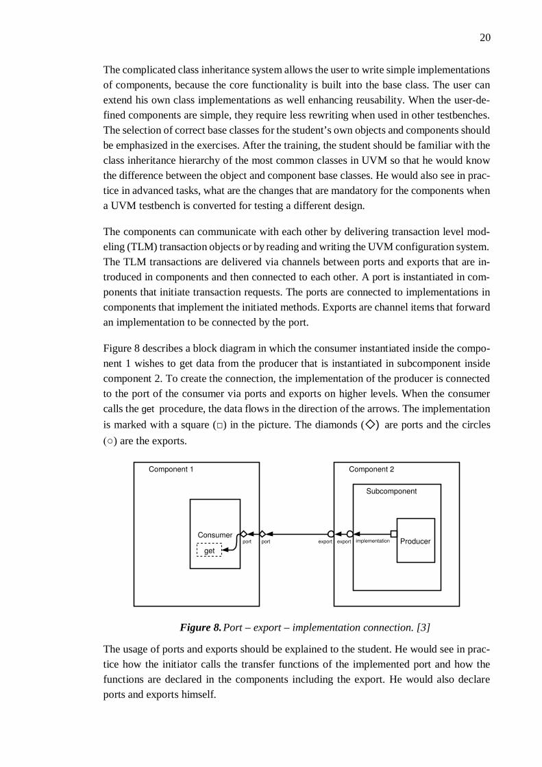
The components can communicate with each other by delivering transaction level mod-eling (TLM) transaction objects or by reading and writing the UVM configuration system.The TLM transactions are delivered via channels between ports and exports that are in-troduced in components and then connected to each other. A port is instantiated in com-ponents that initiate transaction requests. The ports are connected to implementations incomponents that implement the initiated methods. Exports are channel items that forwardan implementation to be connected by the port.
Figure 8 describes a block diagram in which the consumer instantiated inside the compo-nent 1 wishes to get data from the producer that is instantiated in subcomponent insidecomponent 2. To create the connection, the implementation of the producer is connectedto the port of the consumer via ports and exports on higher levels. When the consumercalls the get procedure, the data flows in the direction of the arrows. The implementationis marked with a square (□) in the picture. The diamonds (◇) are ports and the circles(○) are the exports.
Figure 8.Port – export – implementation connection. [3]
The usage of ports and exports should be explained to the student. He would see in prac-tice how the initiator calls the transfer functions of the implemented port and how thefunctions are declared in the components including the export. He would also declareports and exports himself.

21
3.1.2 Macros and methods
UVM includes macros that provide users a shorthand notation for SystemVerilog con-structs. The macros can define object behavior and interaction with the internal UVMmechanisms and assist in reporting. Macros are defined beginning with the grave accentcharacter (`), which should not be confused with the apostrophe (‘).
All the reporting in UVM should be done using reporting macros, because they handlethe filtering of unneeded messages to reduce processing overhead [3]. The reporting mac-ros also automatically provide file names and line numbers in the prints done by thetestbench and ensures that the user does not accidentally prevent printing of warning anderror messages by setting a verbose level. Examples of reporting macros are shown inProgram 13. The parameters for the macros are the message identification, INFO1 andWARN1 in the program, and the message to be printed [5]. The uvm_info macro can alsoinclude a level of verbosity for filtering of the messages. A sformatf method is used toformat the info message using the syntax similar to printf function in the C language.There are also similar macros for errors and fatal errors.
`uvm_info("INFO1", $sformatf ("data: %0d", data), UVM_LOW)`uvm_warning("WARN1", "This is a warning")
Program 13. Examples of UVM reporting macros.
Other important macros are the factory registration macros [5]. The factory is a classinternal to the UVM mechanisms, which takes care of creating UVM objects and compo-nents and maintains a list of every instantiation done in the testbench. All the objects andcomponents should be registered to the factory by performing a factory registrationmacro:
`uvm_component_utils(my_class)
There are separate registration macros for objects and components. The purpose of theregistration macro is to help the factory to keep a record of every object and componentin the testbench. The classes can be later substituted with another compatible class byusing the factory without changing the underlying component hierarchy code. In additionto the registration macro, the class instantiation should be done using a special factorymethod instead of calling the constructor function directly. The factory method will callthe constructor function of the classes, but also performs additional procedures that aremandatory for the function of the UVM factory. The syntax for the factory method forinstantiating an imaginary class comp is following:
comp_h = comp::type_id::create("comp_h", this);
The factory registration macro should be introduced to the student when he is instructedto declare his first class to ensure the correct structure of the testbench from the beginning.

22
Reporting macros should be introduced so that the uvm_info would be explained first andthe knowledge would be deepened later by providing the more severe alternatives.
Another important internal mechanism of UVM is the configuration database. The con-figuration database stores variables to be read in the components to allow communicationacross the testbench during runtime. In addition to the variable name and value, a scopeis set that dictates the hierarchical path to the component using the value. The configura-tion database can be written and read by every component by using functions set and get.Usage of the configuration database enhances efficient reuse by making the componentsin the testbench more configurable.
The configuration database would be used in the exercises to deliver a pointer to the DUTinterface from the top-level module to the testbench components that communicate withthe DUT. More advanced exercises could also mention other configuration for thetestbench, but the delivering of the virtual interface would be enough to show the functionof the database.
The simulation of UVM is divided into phases. The sequence of the UVM phases isshown in Figure 9. There are 21 simulation phases in total and they can be divided intothree categories. In the beginning of the simulation the build time phases construct thetest environment by building components using the factory, form the connections betweenthe TLM channels and configure all the components using the configuration database.The build time phases do not consume simulation time.
Figure 9. UVM Phases. [5]

23
After the test environment has been constructed, the run-time phases are started and thesimulation time is consumed. The run-time phases carry out the actual simulation wherethe test case is run for the DUT. After the test has been stopped, simulation time is notconsumed anymore and cleanup phases collect the results of the test case and report them.
The functionality of components in every simulation phase is configured by providingspecific phase methods in the class declarations. Not all the 21 simulation phase methodshave to be declared in every class declaration, but only the methods where the componentshould have user-specified activity. The high number of phases allows a common under-standing on what should happen in each phase of the simulation when verifying complexdesigns, even when the components are developed by different engineers.
An example of the usual phase methods for an imaginary class is shown in Program 14.The build phase method creates components that are lower in the hierarchy by using thefactory instantiation method. The connect phase function follows the build phase and per-forms the connections between the components created in the build phase. On run phase,an imaginary data object is created and commanded to start execution. The run phaseconsumes time during simulation, so the type of the phase method is task. All the phasetasks have to use specified method names and be parameterized by the UVM phase as inthe example. [5]
function void build_phase(uvm_phase phase); // create two components of type comp comp1_h = comp::type_id::create("comp1_h", this); comp2_h = comp::type_id::create("comp2_h", this);endfunction: build_phase
function void connect_phase(uvm_phase phase); // Call the connect method to connect the implementation to export Comp1_h.conn_imp.connect(comp2_h.conn_exp);endfunction: build_phase
task run_phase(uvm_phase phase); ... // create a object of type obj and call its start method obj_h = obj_type::type_id::create("obj_h"); obj_h.start( ... ); ...endtask: run_phase
Program 14. Examples of phase methods.
The exercises should focus on the most important build, connect and run phases, becausethese phases implement the basic methods of UVM. The instructions could mention thatthere are more phases as well, but the testbenches to be designed in the exercises wouldnot require declaring methods for them.

24
3.2 UVM architecture
The architecture of a UVM testbench consists of user-defined components extending baseclasses in the UVM library [5]. Every component has a name and a parent in the testbenchhierarchy and they are instantiated in the build phase by using the UVM factory in a topto bottom order. An example of a block level UVM testbench is introduced in the Figure10. The example in the figure contains an UVM environment that is used in multiple tests.The example environment contains agents for interfacing the two bus interfaces and com-ponents for test coverage monitoring and the functional checking of the DUT.
Figure 10. A complete block level testbench. [5]
The UVM architecture will be an important learning objective in the exercises. The stu-dent should be able to distinguish between the test and the environment. He should knowthe most common UVM components on a level that he should be able to declare a simpleUVM testbench himself using a correct hierarchy.
3.2.1 UVM Environment
The environment is the component that describes the physical architecture of thetestbench [4]. It instantiates all the components hierarchically and one environment cancontain multiple sublevel environments. On system level testbenches there could be onetop-level environment that instantiates multiple environments for each block of the de-sign. The same block level environments cold be used for block level testing before inte-gration. The method of building a system level testbench from block level environmentsis often referred to as vertical reuse.

25
The environment contains one or more agents, which communicate with the DUT, andsubscribers, which use the data provided by the agents. An agent is a component thatinstantiates the components that manage the stimulus flow, feed the input data to the DUTand monitor the signals that move between the testbench and the DUT. If the DUT com-municates with multiple interfaces, there is usually one agent per interface. An agentcould have an active or passive role set by the configuration database: an active agentprovides stimulation data for the DUT and a passive one only monitors the transfers.
The first testbench to be designed by the student would be simple and contain only oneenvironment that has one agent. The passive and active roles of the agent could be intro-duced, but not emphasized in the beginning. More advanced tasks could introduce theusage of multiple agents. The student should know after the exercises what the role of theagent is and what components it includes.
The usual components instantiated within the agent are sequencer, driver and monitor.The sequencer is an arbiter that reads sequence objects from a list and controls the se-quence flow. The sequences are delivered as TLM transactions. The driver receives theTLM transactions from the sequencer and drives them to the DUT. Thus, the driver trans-forms the abstract transaction level sequences into pin-level activity in the DUT.
Monitor is a component that follows the activity in the DUT interface and samples it. Thepin-level activity in the DUT is converted into TLM transactions and sent out for analysis.The monitor includes an analysis port that delivers TLM data further into the testbench.In a passive agent, the sequencer and the driver are turned off and only the monitor isactive.
The data sent out by the monitor is analyzed by the subscribers that implement analysisexports, which connect to the analysis port in the monitor. The subscribers usually resideoutside the agent in the environment, but can be instantiated in the agent as well in morecomplex designs. The subscribers answer to the questions “How does the DUT perform?”and “How much have we tested so far?” [4]
Coverage collector is a subscriber that gathers functional coverage data [5]. It samplesall the transactions sent by the monitor and uses the data to increment counters in cover-groups. Covergroups specify the signals and conditions that are to be monitored as cover-points. The counter values for each coverpoint represent real-time functional coveragedata of situations that have and have not been tested.
Scoreboard is the UVM component that determines if the DUT functions properly. Itspecifies a reference model and compares the output produced by the DUT to the refer-ence. In simple designs the reference the model and comparator can be declared in a singlecomponent, but it is also possible to use separate components or even use an outsidemodel of the DUT as the reference. [5]
26
The exercises should include a coverage collector and a scoreboard, because they arecomponents that use the data provided by the monitor and implement the testbench func-tionality that answers the questions “Have we tested enough?” and “Does the DUT per-form correctly?” The student should examine test coverage data provided by the coveragecollector he has declared and verify the functionality of the DUT by comparing its outputto a functional model.
3.2.2 UVM Tests
Test is the top-level component of a UVM testbench [4]. The test controls the buildingand configuration of the test environment, selects the stimulus sequence to be used in thetest and controls the simulation process. There can be multiple tests using the same envi-ronment but different sequences and configuration. It is common to declare a base testclass that instantiates the environment and does the necessary configuration, and thenextend tests from it to cover different test cases for the DUT.
Sequences are lists of objects that are delivered to the sequencer in the agent [5]. Thesequencer processes the list item by item. The sequences can be layered on top of eachother to provide means of describing the complex transactions that include multiple layerssuch as USB 3.0 or PCI express. A higher-level sequence can control the transactions ona higher abstraction level and command the lower level sequences that work closer to thehardware.
Variables in sequences can set to be randomized to allow randomized testing. Constraintscan be set to limit the randomization to include a specific value range or to set distribu-tions so that a signal can be for example set high 95% of the time, but low for the rest.The concept is used in constraint random testing that was part of the learning require-ments.
The simulation run is controlled by an objection mechanism [4]. In the start of the runphase the test raises objection and the simulation runs until all the objections have beendropped. This way a component can inform the testbench that it is not ready yet for stop-ping the simulation by raising another objection.
If there are multiple tests, the top-level module of the testbench specifies the test to berun by declaring the test name as a parameter for the run_test method:
run_test ("test_base");
The test name can also be given as a parameter to the simulator, if the parameter is notprovided for the run_test method. In terms of reusability, the better way to start the spe-cific test would be to omit the test name from the top-level module and declare it whenstarting the simulation using the UVM_TESTNAME flag. That would allow the user the rundifferent tests without modifying the code.

27
A base test and sequence should be provided ready for the student, so the first exercisescould concentrate on the UVM environment. Later exercises, when the environment isready, should include multiple tests that use a constraint-randomized sequence extendedby the student from the provided classes. The student should also encounter the usage ofobjections. Layered sequences are more advanced UVM concepts and they will not beintroduced in the exercises.
The original learning requirements made by the customer also dictated that the UVMregister abstraction layer (RAL) should be introduced. The RAL provides a way of con-trolling the contents of the registers in the DUT and introduces a convenience layer to theregister and memory locations. As it was later agreed in a meeting that the RAL shouldonly be covered on a lecture basis, the deeper function of the RAL is not covered in thisthesis.
28
4. REQUIREMENTS AND METHODS FOR THETRAINING
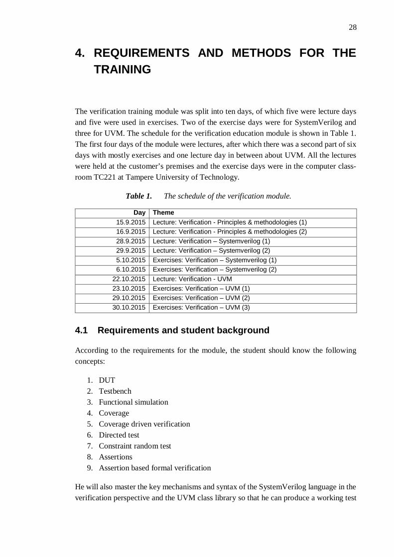
The verification training module was split into ten days, of which five were lecture daysand five were used in exercises. Two of the exercise days were for SystemVerilog andthree for UVM. The schedule for the verification education module is shown in Table 1.The first four days of the module were lectures, after which there was a second part of sixdays with mostly exercises and one lecture day in between about UVM. All the lectureswere held at the customer’s premises and the exercise days were in the computer class-room TC221 at Tampere University of Technology.
Table 1. The schedule of the verification module.
Day Theme15.9.2015 Lecture: Verification - Principles & methodologies (1)16.9.2015 Lecture: Verification - Principles & methodologies (2)28.9.2015 Lecture: Verification – Systemverilog (1)29.9.2015 Lecture: Verification – Systemverilog (2)5.10.2015 Exercises: Verification – Systemverilog (1)6.10.2015 Exercises: Verification – Systemverilog (2)
22.10.2015 Lecture: Verification - UVM23.10.2015 Exercises: Verification – UVM (1)29.10.2015 Exercises: Verification – UVM (2)30.10.2015 Exercises: Verification – UVM (3)
4.1 Requirements and student background
According to the requirements for the module, the student should know the followingconcepts:
1. DUT2. Testbench3. Functional simulation4. Coverage5. Coverage driven verification6. Directed test7. Constraint random test8. Assertions9. Assertion based formal verification
He will also master the key mechanisms and syntax of the SystemVerilog language in theverification perspective and the UVM class library so that he can produce a working test

29
environment using UVM. The requirements covered both the lectures and exercises. Therequirements for the content of the exercises were redefined in meetings with the cus-tomer and the final learning objectives are explained in the chapters 5 and 6 that coverthe planning of the exercises.
The participants in the education were professionals in information technology and tele-communications with experience of programming and software development. Some hadformer hardware design experience as well and some participated in the digital designeducation module. It was dictated by the customer that because verification is program-ming by nature, the module should be introduced to the students so that they were essen-tially learning a new programming language.
4.2 Tools used in the exercises
The exercises were designed to be run using the Mentor Graphics Modelsim simulationtool. Modelsim was chosen, because it is created by a major vendor and therefore a com-mon tool in the industry. Modelsim also has the UVM library included, so there was noneed to compile it. Mentor Graphics has also a more advanced QuestaSim verificationtool available, but it was decided that it would offer no real benefit in this case and theessential usage of Modelsim is completely similar.
Instead of running the Modelsim directly on the class workstations running Windows 7,a Linux virtual machine was decided as a platform. The Linux environment allows theuse of make automation tool that eases the compiling and running of the simulations be-cause a multitude of parameters are needed for UVM simulations. Using a virtual machinealso allows a diverse set of text editors – the students had a choice of common tools fromboth the Windows and Linux environments including Notepad++, Emacs, Gedit and vi.
The Linux Modelsim packages already available on the department network drive limitedthe selection of the operating system into Red Hat Enterprise Linux or its derivatives.Centos Linux 6 was selected, because it is a free community-driven alternative to RedHat Enterprise Linux and the installation packages were compatible with it. There wasalso a newer Centos 7 version available, but the more traditional Gnome 2 user interfaceof Centos 6 was more appropriate for usage in class compared to the Gnome 3 in CentOS7, and it was already proven to work on other courses on the department in which a virtualmachine has been utilized.
The students had no access to any network drives because of their temporary guest ac-counts. Therefore, every student was given a USB memory for storing his or her databetween exercise sessions. The virtual machine was reset every night to ensure similarexperience between workstations and the students were advised to either use a temporaryfolder on the Windows host machine that would be shared for the virtual machine, oralternatively access the USB memory directly from the virtual machine for data storage.

30
4.3 Structure of exercises
The exercises were designed to be completed independently without a need for guidedsessions. The instructions were planned to be delivered to students via the departmentwebsite. The instructions for every exercise were written as a separate web page withlinks to them on the exercise index page. The index page would also offer an overview ofthe learning objectives and the UVM exercise index gave a small overview of the exerciseproject as a whole. An example of UVM index page is shown in Figure 11. The Sys-temVerilog and UVM exercises had both their own websites. Every exercise had moreprecise learning objectives listed in the same format as in the index page.
Figure 11. The UVM exercise index page.
An example of an exercise page is shown in Figure 12. The exercise layout was designedso that all the real tasks to do would be marked with bullets (1. in the figure) to keep theinstructions straightforward. Between the bulleted lists would be body text (2. in the fig-ure) that explains what has been done and what will be done next for motivation. In thefirst exercises, the bullets were very thorough and the student was guided systematically,but the instructions loosened up along the exercises leaving more processing to the stu-dent.

31
Figure 12. An example of an exercise page. 1 describes a bullet with the con-crete task and 2 is body text containing the motivation for the task. 3 is an exam-
ple of a code block.
All the console commands and code blocks were highlighted with monospace font in acolored text box, as shown in Figure 12 (item 3.) A dollar sign ($) was used as the firstcharacter to separate console commands from code examples. Some console commandswere long and would not fit on one line, so a backslash (\) was used to escape the linebreak. Most of the code blocks given were ready to be copied and pasted to the text editorand they were commented when needed using the SystemVerilog syntax. Sometimes thecode blocks gave only a syntax example that should be applied by the student to keep thestudents alert, but these cases should be obvious enough to not cause confusion.
The students were given additional information that would not be crucial for completingthe exercises, but usually offered hints about the task, deeper explanation of methods usedin tasks or some syntax help. The information could also be obtained elsewhere, for ex-ample from language reference manuals or design specifications. These informationboxes were separated from the rest of the text with a colored background and roundedborders. An example of an information block about reporting macros is shown in Figure13.

32
Figure 13. An information block example.

33
5. SYSTEMVERILOG EXERCISES
The SystemVerilog exercises were an introduction to a new language before the studentstarted to learn UVM. Because SystemVerilog is a vast collection of design and verifica-tion toolsets and most of the verification side of the language is utilized in UVM, it wasdecided that these exercises should concentrate on the design side of SystemVerilog. Thestudent was encouraged to use validation and verification methods usable by hardwaredesigners and was introduced to low level testbenches.
5.1 Learning objectives
The preliminary learning requirements made by the customer dictated that the studentshould know all the key mechanisms and syntax of SystemVerilog in the perspective ofverification. This should have included syntax and basics, object-oriented programmingwith SystemVerilog, testbenches with SystemVerilog, constraints random stimulus andassertions. In a meeting with the customer it was agreed, that the object-oriented proper-ties and constraints random stimulus will be introduced in the UVM exercises wellenough and if the exercises would introduce an object-oriented testbench, it would be toosimilar to UVM already offering no learning benefits as such. It was decided that theSystemVerilog exercises could concentrate on the design side of the language. It was alsohoped, that AMBA AXI bus would be used in the example designs.
The agreed learning objectives dictated that after the exercises the student should be ableto create simple hardware designs with SystemVerilog knowing the basic syntax of thelanguage. He should know how assertions are used in hardware design for validation andhow testbenches can be used for simulation support and verification. The exercises shouldgive an insight on how laborious it is to create a self-checking testbench on a low-levellanguage as a motivation for the UVM training.
The final learning objectives are very design-oriented compared to the focus on verifica-tion in the education module. This was decided, because a verification engineer shouldknow the basics of design as well. Not all the students attended the first education modulethat concentrated on design, and while the usage of VHDL language that was used thereis similar, the student should know how the languages differ from each other. In addition,the focus was to introduce the student to a new language and this way he would get amore thorough overview of all the different properties of SystemVerilog. Assertions andtestbenches were emphasized to keep up with the theme of the education module.
The exercises should have concentrated on the latest version of SystemVerilog for design.The language has improvements on older Verilog versions and exercises encouraged us-

34
ing the current syntax. However, some old Verilog structures are still a part of the lan-guage standard and it was predicted that the student would encounter them later. To avoidconfusion later, the most common old syntaxes were introduced and then explained howSystemVerilog has improved them.
5.2 Structure
The exercises built on top of each other and the difficulty of the exercises quickly in-creased from introductory tasks to demanding design work. After the exercises, the stu-dent should have experienced a complete SystemVerilog design flow including a smallmodule declaration, validation and verification of the design using assertions andtestbenches and connection to a commonly used AMBA AXI communication bus usingthe SystemVerilog interfaces.
The exercises started with an introduction to the tools using a ready Hello World filewritten in SystemVerilog. Then, the students were given specifications of simple designsto get familiar with the syntax of the language. The later exercises build on top one of thedesigns made by the students. Along the exercises, they would see that the specificationwas not complete and the deficiencies may lead to errors. Assertions would be added tothe design to catch the erroneous situations and a self-testing testbench would be used tocatch bugs and to see if the assertions are triggered. Finally, a fixed and verified designwould be connected to an AMBA AXI 4-Lite bus and the complete bus-connected modulewould again be verified with a self-checking testbench.
It was planned, that almost every student had enough time to start with the bus connec-tivity, but the testbench for the bus-connected module would be enough of additionalwork for the fastest performers. An estimation of the exercise schedule is shown in Table2. The schedule estimation for each training day was shown to the students but it wasemphasized, that they should not follow it strictly but do the exercises on their own pace.
Table 2. Schedule estimation for SystemVerilog exercises
Monday 5.10. Headline9:00 – 9:45 Setting up the simulation environment, Hello World exercise
9:45 – 10:30 First design with SystemVerilog: adders10:45 – 11:30 Adders12:30 – 14:00 Decrypter module14:15 – 15:45 Validation with assertions
Tuesday 6.10.9:00 – 10:30 Verification with a testbench
10:45 – 11:30 Improving the design based on validation and verification12:30 – 14:00 Bus wrapper for the module13:15 – 14:00 Bus wrapper for the module14:15 – 15:45 Bus wrapper for the module

35
5.2.1 Exercise 1: Introduction to SystemVerilog
The first exercise was an introduction to SystemVerilog. It introduced the usage of mod-ules and the procedural statements, which were used as the basis in further exercises. Inaddition, the exercise served as an introduction to the simulation system used in the exer-cises so that the student could simulate his designs independently during the followingexercises.
The first thing to do was to prepare the environment used in the exercises. This would bethe first time the student would start the virtual machine, so it had to be set up. There wasa sourcing script on the virtual machine that pointed the path variable of the operatingsystem to the Modelsim installation folder and set up licensing information to allow run-ning the simulation environment. The student was instructed in setting up the environ-ment and then to test it by simulating a ready Hello World type design that is shown inProgram 15.
module hello;
initial begin $display ("Hello World"); $info ("Edutech 2015"); #2 $finish; endendmodule: hello
Program 15. Hello World code used as the first SystemVerilog example
Running the example was instructed systematically. The student should first create hisown design library and map it to a special library called Work that Modelsim uses forsimulation files. Then the code can be compiled and simulated in console. The simulationenvironment should print “Hello world” and “Edutech 2015” and then finish.
After the student had tested the simulation environment, it was time to start the first de-sign. An asynchronous adder would be used as an example, because it is simple enoughand still a useful and quite a common design. The module would take in two 8-bit valuesfrom A and B operand inputs, add them together and output the result using 8-bit resultand 1-bit carry signals. The student was instructed to create the structure for their firstmodule systematically according to the Program 16, but had to combine some informationto model the functionality of the module. Hints were given for continuous signal assign-ment and concatenation and for basic arithmetic operators.
// Start by declaring a module called adder:module adder (operand_a_in,operand_b_in,carry_out,result_out);
// Declare ports as inputs or outputs:// Inputsinput [7:0] operand_a_in;input [7:0] operand_b_in;

36
// Outputsoutput carry_out;output [7:0] result_out;
// Add functionality and end the module
// When ready, end the module withendmodule: adder
Program 16. Structure of the module, as instructed in the exercise instructions
The first example in Program 16 uses the non-ANSI syntax of Verilog language. All theinput and output ports are first defined in the port list in module declaration and then laterdeclared inputs or outputs, so there is some unneeded redundancy. This is still very com-mon design practice and it was introduced in the beginning before a reason for the new,less verbose ANSI method was explained. An ANSI declaration for the signals in themodule declared in Program 16 is as follows:
module adder (input [7:0] operand_a_in, input [7:0] operand_b_in,output carry_out, output [7:0] result_out);
After the adder was finished, it was simulated using a graphical waveform window ofModelsim. A ready adder.do file, that added the signals to the waveform window andgenerated some test input, was supplied to support the simulation.
The next step was to make a new synchronous adder. The SystemVerilog ANSI methodof declaring a module, in which the directions of the signals are declared directly in themodule port list, was introduced and explained. This task introduced procedures, whichis a central SystemVerilog concept. A synchronous always_ff procedure was instructed,that would trigger its execution every time the clock signal has a rising edge or reset signalgoes low. The module should also be able to do subtraction, controlled by an add_sub
signal, in comparison to the previous task. When add_sub is high, an addition is performedand otherwise the B input is subtracted from A. Controlling the functionality by theadd_sub signal would require an if clause that was introduced as a skeleton syntax forreset handling already in the task.
When simulating the design, the student is advised to create a simple simulation testbenchinstead of a do file. The simple testbench can be declared in the same file as the design asa separate module that instantiates the design, and its purpose is only to initialize thesimulation and generate clock, reset and input values. The basics of testbench design weregiven as an info block that included instructions for usage of initial procedures for clockand reset generation, delays and component instantiation.
After the exercise, the student should already have used most of the key SystemVerilogconcepts. He has declared his own modules with some logic connecting the input andoutput signals and instantiated a module inside a testbench. He has used a procedure in a

37
synchronous module that follows clock and reset signals that are generated for simulationby the testbench using delays and initial procedures.
5.2.2 Exercise 2: Decrypter module
The second exercise introduced more design concepts of SystemVerilog, most im-portantly data types, parameters and state machines. The design in this exercise served asa base for next exercises in which the design is validated and verified using assertions andself-checking testbenches, and finally connected to the AMBA AXI bus.
The students were given a specification of a hardware module that is depicted in the Fig-ure 14 as process P4. The module is a part of a system, in which data is first encrypted(process 1) and written to a FIFO, then written to the shared memory (process 2), readfrom the memory and written to another FIFO (process 3) and finally decrypted and out-put (process 4) [20]. The encryption is done with permutation of the data by cutting it inhalf and rotating the halves after which the data is encrypted with a bitwise exclusive or(XOR) operation with a key value. The students are instructed to create a decrypter mod-ule that reverses the encryption operation that is the P4 process in the Figure 14.
Figure 14. The complete encrypt-decrypt system. P4 is the process that the stu-dent has to implement in the exercise. [20]
The decrypter module was chosen as an example design for the exercises, because thesystem was already used in the SystemC exercises of the hardware design module of theeducation. This gives continuity to the exercise project, because a part of the studentsattended both the modules. The operation of the module is simple enough, so that mostof the time would be used in learning the language and not polishing a complex algorithm.The module also requires handshaking signals and is a candidate to be connected viaAMBA AXI bus in later exercises, because it is already a part of a complete system inwhich small components communicate with each other.

38
The specification for the module stated, that it should have a default data width of 32 bits,but should be able to be synthesized with all data widths that are multiples of 2. Thiswould require usage of a parameter in the module declaration. The encrypted signal andencryption key would be input via separate ports and the decrypted signal has its ownoutput port. The operation would be controlled by a master component with enable andvalid signals so that the encoding starts with a rising edge of enable and when ready, thevalid signal is set to indicate that the output port has a valid decrypted value. When thevalid signal is high, the master confirms that the data is read by lowering the enable signal.
The student was encouraged to use a state machine with enumerated states for operation.The states would be for example idle, processing and ready, and a state graph matchingthe specification is depicted in Figure 15. It can be seen from the graph that the functionof the system is not specified when the enable signal falls before the valid is set. Thestudent is advised to draw a state diagram and find a fix for the errors in the specification.One example of an additional state transition that would fix the problem but lose the latestinput data is marked in the Figure 15 with red.
Figure 15. A state diagram for the decrypter module.
After the component was ready, it had to be simulated with a simple testbench. Therewere no additional instructions for creating the testbench, but the student should be ableto apply experience from the first exercise to generate the clock, reset and input signalsand run the simulation.
After finishing the exercise, the student should have more design experience with Sys-temVerilog. He should have a component that matches the specification. The componentwould be used as an example design in the rest of the exercises. Because the followingexercises build on top of the design in this exercise, extreme care should be taken thatevery student is able to finish this exercise and all the problems should be answered with-out long delays.

39
5.2.3 Exercise 3: Assertions and testbenches
The third exercise introduced the student to validation and verification with SystemVeri-log. The student was advised to use assertions to validate his own design and to verify thedesign using a self-checking low-level testbench that he has designed himself. Accordingto the learning objectives in the module, the exercise 3 is the most important part of theSystemVerilog exercises.
The first task was to add assertions to the decrypter design. The student had to find themost critical points in the design and create assertions that would trigger if there is achange of losing data or corrupting it. The student was instructed to add at least threeassertions. One valid assertion would be to check that the data width parameter is a mul-tiple of two, because it is stated in the specification of the component.
Basic usage of assertions was instructed in an information block. The block containedexamples for concurrent and immediate assertions with implication operators and systemfunctions $rose, $fell, $stable and $past. One of the more complex example assertionsis shown in Program 17. The assertion states that valid signal must rise after two cyclessince enable has risen, but only if the component is not in reset.
assert property (@(posedge(clk)) disable iff(~rst_n) $rose(enable_in) |-> ##2 valid == 1);
Program 17. example assertion
The student was reminded that the reason for assertions is to catch unwanted performanceand not to duplicate the hardware model [17]. For the SystemVerilog code in Program18, the first assertion in Program 19 checks that when data is 0x05, the signal a is set onthe next clock cycle. This assertion would be a poor one because it is bound to always betrue according to the model. The second assertion in Program 20 assures, that the signala is never set in any other case. This is not as certain, because some erroneous code else-where could set the signal a.
if (data = 0'h05) signal_a <= 1;else signal_a <= 0;
Program 18. Code sample for assertion examples.
assert property (data == 0'h05 |=> signal_a == 1);
Program 19. A poor assertion duplicates the hardware model.
assert property (signal_a == 1 |-> $past(data) == 0'h05);
Program 20. A better assertion checks that the signal_a is never set in any other case.

40
The student was advised to simulate the design with various input signals when the as-sertions have been added to see if they are triggered correctly. The simple testbench inexercise 2 could be used in this task. It depends on the assertions and the testbench madeby the student, if the assertions trigger. If the assertions do not trigger, the student shouldbe advised by the assistant to add more input patterns to the simple testbench.
The second task in the exercise was to generate a self-checking testbench to verify thedesign. The testbench should be divided to multiple initial and always procedures thatgenerate the clock and reset signal, give randomized encrypted input and key values tothe DUT and compare the DUT output to the reference values. An example block diagramof the testbench connected to the DUT is introduced in the Figure 16. All the proceduresin the testbench are shown as blocks in the picture. The print result procedure is used forfinal checking after the test is finished. The procedure checks that there are no more un-processed input values in the buffer and if result counters were implemented in the mon-itor procedure it can show a final report indicating if the test was successful or not.
Figure 16. Block diagram of the testbench for the decrypter module.
The student was encouraged to implement some dirty testing as well using all kinds oftransactions that do not follow the specification. Some examples for dirty test inputs weregiven, in which the testbench would lower the enable signal when it should not be doneand change the key when the DUT is still processing the data.
After validation and verification, the student should have found out that the design is notcompletely stable for production and deficiencies in the specification would lead to dataloss or corruption in some cases. The student was advised to improve the design to preventthese situations. One fix would be to improve the handshaking by adding a new signal forthe master to confirm that the output has been read, so glitches in enable signal would notaffect the functionality.
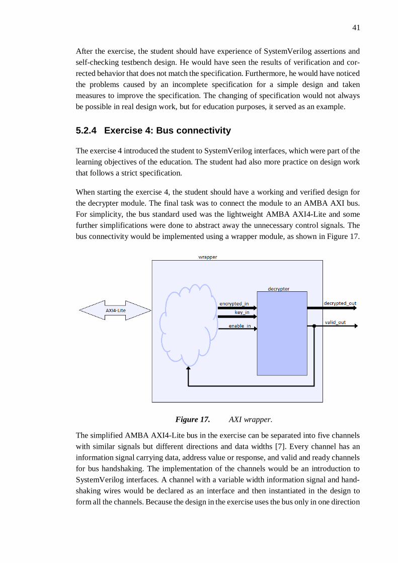
41
After the exercise, the student should have experience of SystemVerilog assertions andself-checking testbench design. He would have seen the results of verification and cor-rected behavior that does not match the specification. Furthermore, he would have noticedthe problems caused by an incomplete specification for a simple design and takenmeasures to improve the specification. The changing of specification would not alwaysbe possible in real design work, but for education purposes, it served as an example.
5.2.4 Exercise 4: Bus connectivity
The exercise 4 introduced the student to SystemVerilog interfaces, which were part of thelearning objectives of the education. The student had also more practice on design workthat follows a strict specification.
When starting the exercise 4, the student should have a working and verified design forthe decrypter module. The final task was to connect the module to an AMBA AXI bus.For simplicity, the bus standard used was the lightweight AMBA AXI4-Lite and somefurther simplifications were done to abstract away the unnecessary control signals. Thebus connectivity would be implemented using a wrapper module, as shown in Figure 17.
Figure 17. AXI wrapper.
The simplified AMBA AXI4-Lite bus in the exercise can be separated into five channelswith similar signals but different directions and data widths [7]. Every channel has aninformation signal carrying data, address value or response, and valid and ready channelsfor bus handshaking. The implementation of the channels would be an introduction toSystemVerilog interfaces. A channel with a variable width information signal and hand-shaking wires would be declared as an interface and then instantiated in the design toform all the channels. Because the design in the exercise uses the bus only in one direction

42
in which the master writes to the slave and never reads, the read address and data channelswill be omitted. The directions of the signals would be declared using modports so thatthe write address and data channels are directed from master to the slave and the responsechannel is reversed.
The student was given a specification for a wrapper module, which instantiates the de-crypter module and connects its input to the AMBA AXI bus. The output of the decrypteris connected directly to output signals. It should be noted that the specification stated thatthe data transfers are written to the latest address sent, so multiple consecutive data trans-fers can be performed. This is not compliant with the AMBA AXI4-Lite specification,where every transaction should be started with an address, and was a simplification foreducation purposes [7]. The fact was emphasized in the exercise instructions.
A simplified AMBA AXI4-Lite bus specification was also included in the instructions[7]. The specification declared all the channels and their signals, the transaction schedulewith timing diagrams of legal transactions and slave response information.
The exercise was very demanding compared to the previous ones. It was predicted thatonly the fastest students would be able to finish the exercise. If the student still had timeafter finishing the wrapper module, an additional task was to build self-checking atestbench for it. The most important content in the exercise was to get familiar with Sys-temVerilog interfaces and the exercises were scheduled so that everyone should be ableto start defining the interface.
After the fourth and final SystemVerilog exercise, the student has experienced a completedesign and verification flow of a simple module that can be connected via a bus interfaceto a larger system. He has used the key design features of SystemVerilog including de-claring parameterized modules with synchronous procedures, state machines with enu-merated state variables and interfaces that have been instantiated to form multichannelbuses. Assertions have been used to ensure valid functionality.

43
6. UVM EXERCISES
The UVM exercises were designed based on old verification exercises that were used onthe course TKT-1410 Suunnittelun varmennus (System Verification) during spring 2013.The exercises were built with OVM and because most of UVM is based on OVM, a largepart of the exercises resembled an UVM testbench already. The exercise planning wasstarted by completing the OVM exercises and finding out all the changes brought byUVM. The testbench in the OVM instructions was then rebuilt from scratch followingUVM guidelines and the exercise instructions were rewritten.
It was predicted that the fastest students would complete the exercises in two days. There-fore, additional exercises were designed, where emphasis was not on new crucial conceptsbut on deeper understanding and reuse. This way the fastest performers would haveenough tasks and can gain more experience with UVM, but still everyone would achievethe learning objectives.
6.1 Learning objectives
The original learning objectives made by the customer stated, that after the educationmodule the student masters the UVM class library and methodology so that he can pro-duce a working test environment using the following UVM mechanisms:
1. UVM Agent2. UVM Scoreboard3. UVM Environment4. UVM Test5. UVM Register Abstraction Layer (RAL)6. UVM Configuration Database7. UVM Factory8. Constraint random with UVM9. UVM Phasing10. Reuse by extending UVM classes
In a meeting with the customer it was agreed, that the objectives stated would otherwisebe followed in the planning of the exercises, but the UVM register abstraction layer wouldbe omitted and it is enough if the register abstraction layer was mentioned on a lecturelevel. The reason for the omitting of RAL was that it was not easily implementable to thesystem and it would require a lot of time to master the concept, so the limited trainingtime should be focused on more important basic principles.

44
The summary of the learning objectives on the exercise instructions state, that the exer-cises will introduce the following principles:
1. The object-oriented properties of SystemVerilog language2. The UVM class library and its usage3. Verifying a design with UVM testbench4. Reusing existing components for new designs
6.2 Procedures and UVM concepts used in the exercises
In a meeting with the customer it was agreed, that UVM experience is more importantthan the internal testbench design guidelines of the company. Therefore, the exerciseswere built to follow the approved guidelines provided by Verification Academy, whichis a training website for verification engineers maintained by Mentor Graphics. [5]
The testbenches were designed so that every stand-alone compilation unit files that areinput to the compiler – the design under test, top-level module of the testbench and thepackage file - had an extension sv and all the class declarations were in separate files withan extension svh, SystemVerilog header. All the class declaration files would have namesthat match the class name and each file would contain only one class declaration. Allthese files would be included in the package file that is imported in the top level, andincludes are not performed anywhere else. Notable exceptions are the uvm_macros.svhfile that is part of the UVM source code and required to be imported in the top level andthe DUT interface description, which also has to be included on top level. This way thewhole testbench would be included in one package and connected to the dut in the top-level module. If the components were used later with another DUT with similar signalsand function, the package could be imported in another top-level design. The package andtop-level file had post-fixes _pkg and _top in the file and design unit name.
The layout of the testbench folder that would be delivered to students at the start of theexercises is shown in Figure 18. All the files marked with green are class description filesthat are included in the package file, which is imported on top level. The red files aregiven to the compiler and the blue dut_if.if file is included in the top-level module file.The other files are to aid in the start of the simulation and not a part of the testbench. Thestudents will be instructed to follow the same layout.
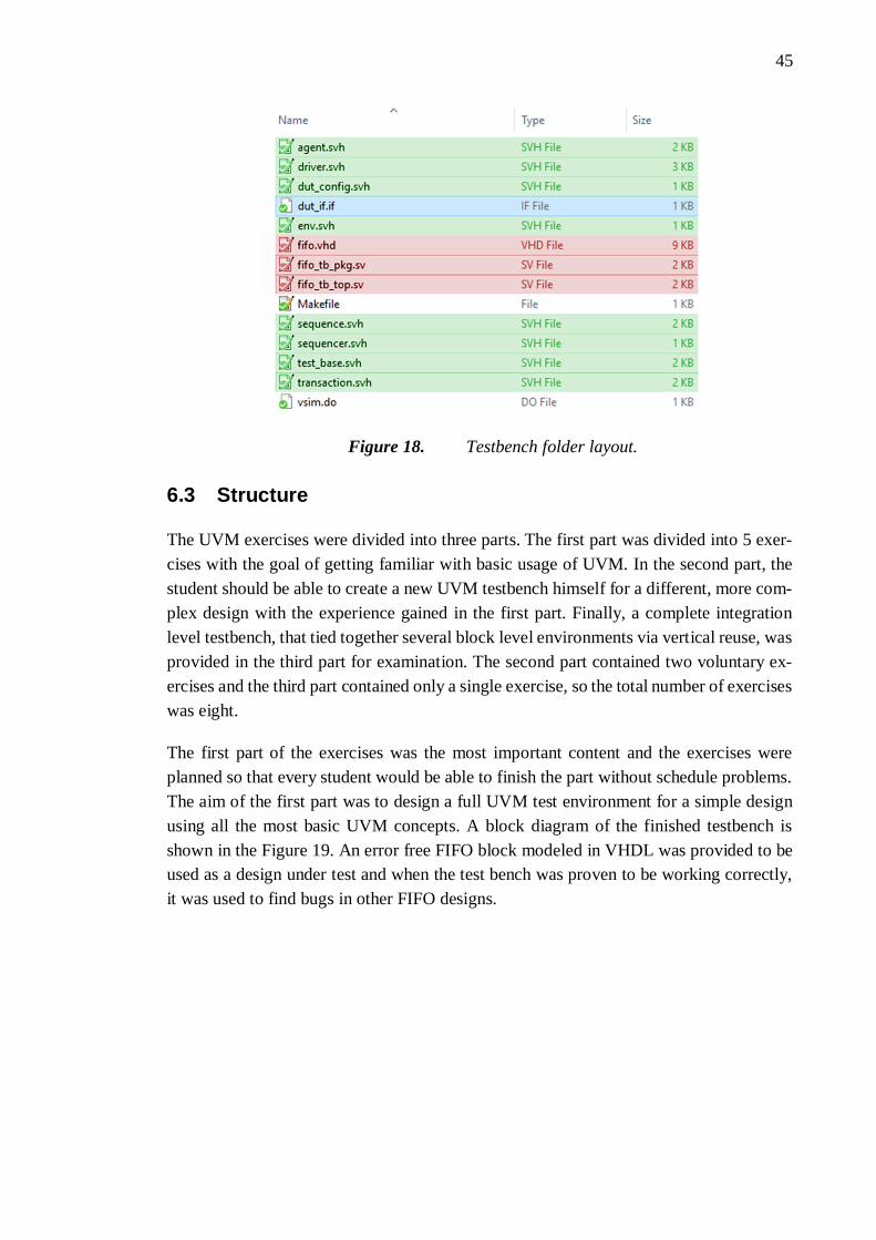
45
Figure 18. Testbench folder layout.
6.3 Structure
The UVM exercises were divided into three parts. The first part was divided into 5 exer-cises with the goal of getting familiar with basic usage of UVM. In the second part, thestudent should be able to create a new UVM testbench himself for a different, more com-plex design with the experience gained in the first part. Finally, a complete integrationlevel testbench, that tied together several block level environments via vertical reuse, wasprovided in the third part for examination. The second part contained two voluntary ex-ercises and the third part contained only a single exercise, so the total number of exerciseswas eight.
The first part of the exercises was the most important content and the exercises wereplanned so that every student would be able to finish the part without schedule problems.The aim of the first part was to design a full UVM test environment for a simple designusing all the most basic UVM concepts. A block diagram of the finished testbench isshown in the Figure 19. An error free FIFO block modeled in VHDL was provided to beused as a design under test and when the test bench was proven to be working correctly,it was used to find bugs in other FIFO designs.

46
Figure 19. The final testbench after finishing exercise 5.
As in SystemVerilog exercises, an estimation of a schedule was given to the students butit was emphasized, that everyone does the exercises on their own pace. The estimation isshown in Table 3.
Table 3. Schedule estimation for UVM exercises.
Friday 23.10. Headline9:00 – 9:45 Introduction to UVM
9:45 – 10:30 Creating classes: UVM monitor10:45 – 11:30 Creating classes: UVM monitor12:30 – 14:00 Subscribers and analysis ports14:15 – 15:00 Subscribers and analysis ports15:00 – 15:45 Automatic checking: UVM Scoreboard
Thursday 29.10.9:00 – 10:30 Automatic checking: UVM Scoreboard
10:45 – 11:30 Automatic checking: UVM Scoreboard12:30 – 14:00 Randomized tests14:15 – 15:45 Randomized testsFriday 30.10.9:00 – 10:30 Verifying a design with UVM testbench
10:45 – 11:30 Verifying the decrypter12:30 – 14:00 Verifying the decrypter14:15 – 15:45 Verifying the decrypter
Table 4 shows a summary of the exercises and how they connect to the original learningobjectives made by the customer. I in the table means that the content has been introducedbut not mastered after the task. X marks that the objective is an integral part of the exer-cise. As can be seen from the table, the first exercise introduces only a few concepts but

47
as the concepts are used in later exercises as well, the most basic principles get a lot ofrepetition and deeper explanation. Coverage, that was the theme of the third exercise, wasnot mentioned in the original learning objectives for the UVM part of the education butcoverage-driven verification was listed in the main topics for the verification module,which is why the table does not show improvements in learning between exercises 2 and3. The exercise 5 only includes running the final testbench to find bugs in designs. There-fore, the structure of UVM is not focused on in this exercise.
Table 4. Learning objectives fulfilled in each exercise.
Exercise 1 2 3 4 5 6 7UVM Agent I X X X X XUVM Scoreboard X X XUVM Environment I X X X X XUVM Test I X X X XUVM Register Abstraction Layer (RAL) IUVM Factory I X X X XConstraint random with UVM X X X XUVM Phasing I X X X X XReuse by extending UVM classes X X X
This chapter explains the contents of all the exercises precisely. The precise explanationdescribes the amount of work the student has to do in each task, but on the other hand, itprovides an insight of the UVM principles that would be required for creating a completetestbench. The code examples in this chapter support the theory of UVM architecture inSection 3.2.
6.3.1 Exercise 1: Introduction to UVM
The purpose of the first UVM exercise was to introduce the student to UVM. The exercisewas planned to be more about exploration of UVM concepts and less about producingnew code. The decision was made, because producing the whole testbench would take alot of time and most of the work would be unnecessary repetition. In addition, the ready-made code would function as a syntax example that would help the student get familiarwith the object-oriented side of SystemVerilog language and concepts in UVM. Inspect-ing a ready-made code that is ready for simulation helps to understand the proceduresneeded for producing new code.
The student was provided with a basic UVM testbench that was used to verify that thesimulation system runs correctly. After running the simulation for the first time, the maintask in the exercise was to find out what was the purpose and function of all the ready-made components. Figure 20 shows a block diagram of the state of the testbench that isdelivered to the student.
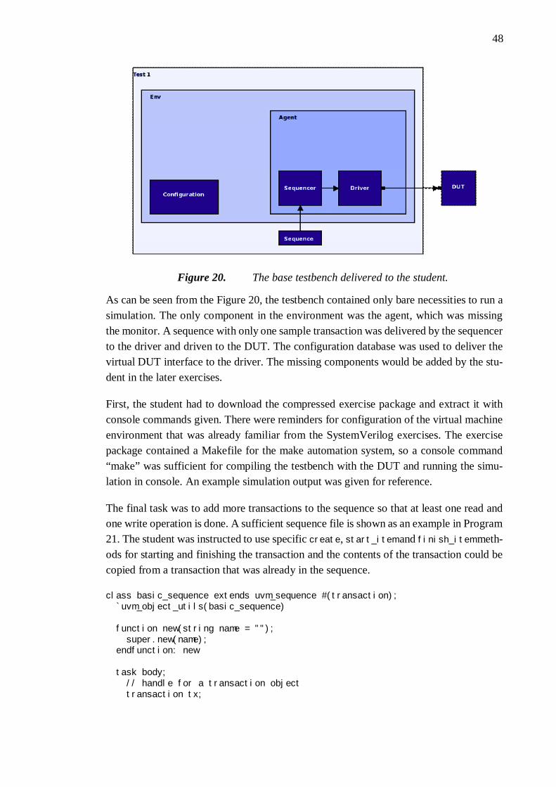
48
Figure 20. The base testbench delivered to the student.
As can be seen from the Figure 20, the testbench contained only bare necessities to run asimulation. The only component in the environment was the agent, which was missingthe monitor. A sequence with only one sample transaction was delivered by the sequencerto the driver and driven to the DUT. The configuration database was used to deliver thevirtual DUT interface to the driver. The missing components would be added by the stu-dent in the later exercises.
First, the student had to download the compressed exercise package and extract it withconsole commands given. There were reminders for configuration of the virtual machineenvironment that was already familiar from the SystemVerilog exercises. The exercisepackage contained a Makefile for the make automation system, so a console command“make” was sufficient for compiling the testbench with the DUT and running the simu-lation in console. An example simulation output was given for reference.
The final task was to add more transactions to the sequence so that at least one read andone write operation is done. A sufficient sequence file is shown as an example in Program21. The student was instructed to use specific create, start_item and finish_item meth-ods for starting and finishing the transaction and the contents of the transaction could becopied from a transaction that was already in the sequence.
class basic_sequence extends uvm_sequence #(transaction); `uvm_object_utils(basic_sequence)
function new(string name = ""); super.new(name); endfunction: new
task body; // handle for a transaction object transaction tx;

49
// Make a write to the DUT tx = transaction::type_id::create("tx"); start_item(tx); tx.data_to_DUT = 3; tx.write_enable = 1; tx.read_enable = 0; tx.rst_n = 1; finish_item(tx);
// Make a read from the DUT tx = transaction::type_id::create("tx"); start_item(tx); tx.data_to_DUT = 0; tx.write_enable = 0; tx.read_enable = 1; tx.rst_n = 1; finish_item(tx);
// Make a clearing transaction in the end tx = transaction::type_id::create("tx"); start_item(tx); tx.data_to_DUT = 0; tx.write_enable = 0; tx.read_enable = 0; tx.rst_n = 1; finish_item(tx);
#10;
endtask: bodyendclass: basic_sequence
Program 21. sequence.svh file contents after completing exercise 1.
The first exercise was a very straightforward introduction to UVM. After the exercise,the student should be familiar with the UVM class library and its usage. He should haveexamined the most basic UVM classes and found out their purposes. He has also experi-ence of running simulations in the Modelsim tool using the make automation system.
6.3.2 Exercise 2: Creating classes
The objective in the second exercise was to introduce the student to class declarations inUVM focusing on the monitor component. The monitor was the only component that wasmissing from the agent, which is a key component in UVM architecture. The exercisealso explained the architecture of UVM environment by teaching the student to instantiatehis first own component in the hierarchy.
A block diagram for the system the student would have after the exercise is shown in theFigure 21, where the new monitor component is highlighted in yellow. As the exercisewas the first introduction to UVM class creation, the instructions were very straightfor-ward and the exercise could be completed by following the instructions systematicallycopying and pasting all the code lines provided.
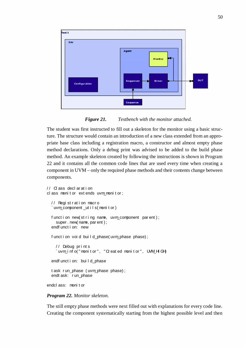
50
Figure 21. Testbench with the monitor attached.
The student was first instructed to fill out a skeleton for the monitor using a basic struc-ture. The structure would contain an introduction of a new class extended from an appro-priate base class including a registration macro, a constructor and almost empty phasemethod declarations. Only a debug print was advised to be added to the build phasemethod. An example skeleton created by following the instructions is shown in Program22 and it contains all the common code lines that are used every time when creating acomponent in UVM – only the required phase methods and their contents change betweencomponents.
// Class declarationclass monitor extends uvm_monitor;
// Registration macro `uvm_component_utils(monitor)
function new(string name, uvm_component parent); super.new(name,parent); endfunction: new
function void build_phase(uvm_phase phase);
// Debug prints `uvm_info("monitor", "Created monitor", UVM_HIGH)
endfunction: build_phase
task run_phase (uvm_phase phase); endtask: run_phase
endclass: monitor
Program 22. Monitor skeleton.
The still empty phase methods were next filled out with explanations for every code line.Creating the component systematically starting from the highest possible level and then

51
fine-tuning the contents of the methods helps the student to keep focus on the task. Thisorder also prevents blind copying from the exercise instructions, because the student hasto be more alert when the file is not constructed line by line in a linear order. Between theinstructions, the student was provided with additional information and reminders aboutUVM phases, the configuration database and the info reporting macro with verbosity lev-els.
The first thing that the monitor should be able to do is connection to the DUT interfaceas shown in Figure 22. The connection is done by getting the configuration object con-taining a virtual interface handle from the configuration database. The configuration ob-ject was already created in the test and used by the driver. To read the configuration da-tabase the monitor needs variable handles for the configuration object and the virtual in-terface. Creation of the handles was instructed to the student using the following lines:
dut_config dut_cfg;virtual dut_if dut_vi;
Figure 22. Delivering DUT interface to monitor
The configuration object is read and connected to its handle by using the get method ofthe configuration database and the virtual interface is then connected to the interface han-dle as shown in Program 23. If for some reason the configuration object cannot be fetched,the testbench would not be able to run and therefore the fetching is enclosed in a condi-tional clause that ends the simulation using the uvm_fatal macro in case of a failure.
// Get the configuration object from config DBif(!uvm_config_db#(dut_config)::get(this,"", "dut_configuration", dut_cfg) ) `uvm_fatal("NOVIF", "No virtual interface set");
// Connect the handle to the virtual interface in the objectdut_vi = dut_cfg.dut_vi;
Program 23. Getting the object from configuration database in the build phase method
The final thing for the student to fill out in the monitor in this exercise was the run phasemethod that contains all the functionality of the component. The run phase contains a loopthat runs infinitely until the simulation is forced to stop. On every iteration of the loop,

52
the monitor reads the status from the DUT interface into a transaction object. The runphase method should be completed by copying the code lines in the instructions is shownin Program 24. The student was shown how to copy the input data of the DUT to thetransaction object, but he had to apply the information to copy all the remaining signals.As there were no components reading the transaction object yet, the student was in-structed to add a debug print in the run phase loop. A more advanced usage of the report-ing macro, which prints the contents of the data, is used in the example in Program 24,but printing for example “Got data” would be sufficient in this exercise. In the example,the contents of the data are printed using a psprintf method and its usage was instructedin the information block about the info reporting macro.
task run_phase (uvm_phase phase); forever begin: mon_loop // Transaction handle transaction tx;
// Wait for clock tick and copy DUT state to transaction @(posedge dut_vi.clk); tx = transaction::type_id::create("tx"); tx.rst_n = dut_vi.rst_n; tx.data_to_DUT = dut_vi.data_to_DUT; tx.write_enable = dut_vi.we_out; tx.read_enable = dut_vi.re_out; tx.data_from_DUT = dut_vi.data_from_DUT; tx.full = dut_vi.full_in; tx.one_p = dut_vi.one_p_in; tx.empty = dut_vi.empty_in; tx.one_d = dut_vi.one_d_in;
// Write the transaction object to analysis port ap.write(tx);
// Debug prints `uvm_info("monitor", $psprintf("Got data: to: %0h, write: %b, read: %b, from: %0h", tx.data_to_DUT, tx.write_enable, tx.read_enable, tx.data_from_DUT), UVM_HIGH) end: mon_loopendtask: run_phase
Program 24. Run phase task in the monitor
The final task in the second exercise was to connect the component to the testbench. Thestudent was reminded that the correct place to instantiate the monitor would be inside theagent. The instructions advised to include the code file in the testbench package and createa handle that the monitor is instantiated to in the agent using the UVM factory call. Thestudent was bound to encounter an example of component instantiation in the agent,where the driver and the sequencer were already in place, so there were no step-by-step

53
instructions. After the monitor had been connected, its function was tested with simula-tion.
After the second exercise the student should have experience of declaring his own UVMclasses and instantiating them to the testbench. He would know which methods are neededat the minimum for a component declaration and when the methods are run in the scopeof simulation. He has also read a configuration object from the configuration databaseusing a ready code snippet and connected the contained virtual interface to a handle, butat this point it cannot be required that he understands the usage of configuration databaseor virtual interfaces and could produce similar code himself. It is only mandatory to knowthe reason, why the process has been done.
The exercise is straightforward, but there are two possible problem points. The studenthas to examine the DUT interface declaration file to find out names of the signals in thevirtual interface. They have to be copied in the run phase task to the transaction objectthat has some differences in the signal names. Another danger point is that the order ofthe include macros in the package file is crucial for the compiler. For example, an agentthat includes the monitor cannot be compiled, if the monitor has not yet been declared.These are not instructed in the exercise and the student has to figure them out himself, butthe assistant should be ready to help if students are stuck. Wrong order of compilationand faults in signal names are usual sources of errors, so first-hand experience would helpto keep them in memory.
6.3.3 Exercise 3: Subscribers and analysis ports
The third exercise introduced a coverage collector to the testbench as shown in Figure 23.The coverage collector is the component that is responsible for coverage-driven verifica-tion in UVM, which was considered an important learning objective. When implementingthe coverage collector, the student was also introduced to the analysis ports that are animportant concept in UVM.
The coverage collector reads the transaction objects sent by the monitor and saves signalstate history to a covergroup. The contents of the covergroup can be examined to getnumerical data of input combinations that have been written to the DUT and the infor-mation can be used to check if the functional coverage of the testing has been sufficient.

54
Figure 23. Coverage collector added to the testbench.
The student was instructed to create a skeleton for a coverage_collector class that is ex-tended from uvm_subscriber like in the previous exercise. The only difference to the skel-eton of the monitor component is that uvm_subscriber is a parameterized base class. Theparameter for the class would be the name of the transaction object class that is receivedfrom the monitor. The student was given an example of parameterized class declarationas shown in Progam 25 and told to parameterize the class with the transaction class. Theinstructions reminded that the skeleton should have a registration macro, a constructorand a build phase method.
class my_class extends base_class #(parameter);
Program 25. declaration of a parameterized class
After the student had a skeleton for the coverage collector, the next step was to start im-plementing the coverage collector functionality. A covergroup was declared with the ex-ample code in Program 26 that the student was told to copy right after the registrationmacro. The covergroup should also be created in the component’s constructor using thenew function. An information block explained that the covergroup consists of cover-points, which are broken into bins. The example code in Program 26 declares one cover-point for the data that is input for the DUT. The student’s task was again to fill out rest ofthe signals that in his opinion should be monitored for coverage. The bins were not de-clared, so for the 32-bit data value the coverpoint was divided evenly by the numericalvalue to 64 bins by default.
covergroup cg; c_data_to_DUT : coverpoint sample_tx.data_to_DUT; ...endgroup: cg
Program 26. Declaration of a covergroup.
55
Another difference between the monitor and subscriber components is that a subscriberreacts on transaction made by other components and not every clock cycle. Therefore, itdoes not require a run phase method but the functionality is implemented in a write func-tion instead. The write function is implemented in the subscriber and then can be calledby the component that is sending data, which in this case would be the monitor.
The student was instructed to declare a write function with code lines that have beencombined together in Program 27. In the example code, the transaction is assigned to avariable and the covergroup cg is updated based on the transaction data using its samplemethod. This would be all that is required for a write function in a coverage collector.
function void write(transaction t); sample_tx = t; cg.sample();endfunction: write
Program 27. Write function of a coverage collector.
The structure of a coverage collector component is simple and the code lines in Program26 and Program 27, when inserted into a component class skeleton, would be enough todeclare a working coverage collector into a UVM testbench. The coverage data is notprinted in the console, but it can be examined by the vcover tool included in the Mod-elSim. In addition, an info block hinted that the covergroup has a get_coverage functionthat returns an integer value of the coverage percentage at the moment it is called. Thevalue can be for example used for printing or finishing the simulation when a desiredcoverage percentage has been reached. The function is internal to the covergroup andcannot be called by the other components in the testbench, but a function declaration wasintroduced that can be used if the student wanted for example to read the coverage valuein the test component. The hint block explained that it is not necessary to implement thisfunctionality now but it could be useful in later exercises.
The student was told to instantiate the coverage collector in the testbench environment.Instantiation was not instructed specifically, but the student was able to refer to the exer-cise 2 instructions if the process was not yet familiar enough. When the component hadbeen instantiated, it was still not connected to any component and the next step was toadd an analysis port connection to the monitor. The connection is highlighted in yellowin Figure 23, where a diamond connection indicates an analysis port and the round con-nection in the subscriber is an analysis export.
In the analysis port system, when a component writes to its analysis port, the write func-tion call is delivered as a broadcast to all the analysis exports that are connected to it.Therefore, a component that implements the transaction and has a write function declaredhas an analysis export and the component that initiates the transfer by calling the writefunction includes an analysis port. Because the monitor is inside the agent and cannot bereached directly by the subscribers outside the agent, the agent should have an analysis

56
port as well, which is connected to the monitor and delivers the transaction through. Thecreation of analysis ports for the monitor and the agent was instructed with code lines inProgram 28. A parameterized class, which has been declared in the UVM library, wasused as it was.
// Declaration of an analysis portuvm_analysis_port #(transaction) ap;
// Create the analysis port in the build phase methodap = new("ap", this);
Program 28. Creation of an analysis port.
After the analysis ports had been created, they had to be connected to the export. A newUVM phase, connect phase, was introduced to the student. The connect phase is executedafter the build phase and its purpose is to make all the connections between components,so it would be a valid place for connecting the analysis ports. The student was advised tocreate connect phase methods to the environment and agent classes, in which a connectmethod of the analysis port class is called to make the connection. The agent had a connectphase method already declared, because the connection between the driver and the se-quencer had already been done. Code lines for the contents of the environment and agentconnect phase methods were given to the student as shown in Program 29. The handlesfor both the analysis ports are called ap in the Program 29 and it should be noted that thecodes expect for the coverage collector’s handle to be cov_h. This might vary in the stu-dent’s own implementation and has to be changed according to the real handle name.
// Connect the agent’s analysis port in the environment’s connect phaseagent_h.ap.connect(cov_h.analysis_export);
// Connect monitor's analysis port in the agent’s connect phasemon_h.ap.connect(ap);
Program 29. Connect phase method contents for connecting the analysis ports
The analysis port in the monitor had now been connected to the export and in the secondexercise, the DUT pin state was copied into a transaction object. The final thing to do wasto add a line of code in the monitor, in which the write function of the analysis port iscalled using the transaction object containing the current state of the DUT inputs andoutputs.
The simulation tool can be set to collect code coverage data during the simulations inaddition to the functional coverage data collected by the coverage collector. To save allthe coverage information to a file to be examined later, the Makefile had a ready com-mand that had been commented out:
#coverage save -onexit vsim.ucdb

57
The command saves the coverage data to a file vsim.ucdb. There were ready targets inthe Makefile for examining the data either in console or by generating an html report outof it. The student was advised to examine the coverage data with simulating the testbenchagain.
The instructions for the exercise were less verbose than in previous exercises. The studentshould have had already some experience of creating a component skeleton and instanti-ating it in the testbench, so repeating the instructions was unnecessary. The new compo-nent declaration was simple, but the student had been provided with enough informationfor declaring even complex coverpoints with specific bins if he wished to. The hardestpart to comprehend in the exercise would be the concept of analysis ports.
The exercise introduced new and important UVM concepts to the student, notably param-eterized classes, analysis ports and covergroups, and after completing the exercise, heshould understand the function and purpose of them. After the exercise, the student shouldbe able to declare his own component classes without any help and instantiate compo-nents in the testbench.
6.3.4 Exercise 4: Automatic checking and randomized input
The fourth UVM exercise introduced the student to the automatic checking capabilitiesof UVM. The exercise introduced the student to UVM scoreboard class, randomizationof transactions and multiple tests that are extended from the previous base test class. Ran-domization enables constraint random testing, which was declared as one of the mostimportant objectives in the verification module. Deriving new tests from a previous classdeclaration introduced the student to the hierarchical reuse of UVM components.
The task was to declare the final basic component, a scoreboard that is highlighted inyellow in Figure 24, in the testbench. The testbench would be capable of automated test-ing and ready for running simple directed tests using the ready test_base component. Asa second task, the testbench was improved by adding a new test class that performs con-strained randomized testing with a different sequence. The exercise was hardest of thefirst part in the UVM exercises and most of the implementation was left for the student.Only the necessary guidelines for completing the exercise were given.
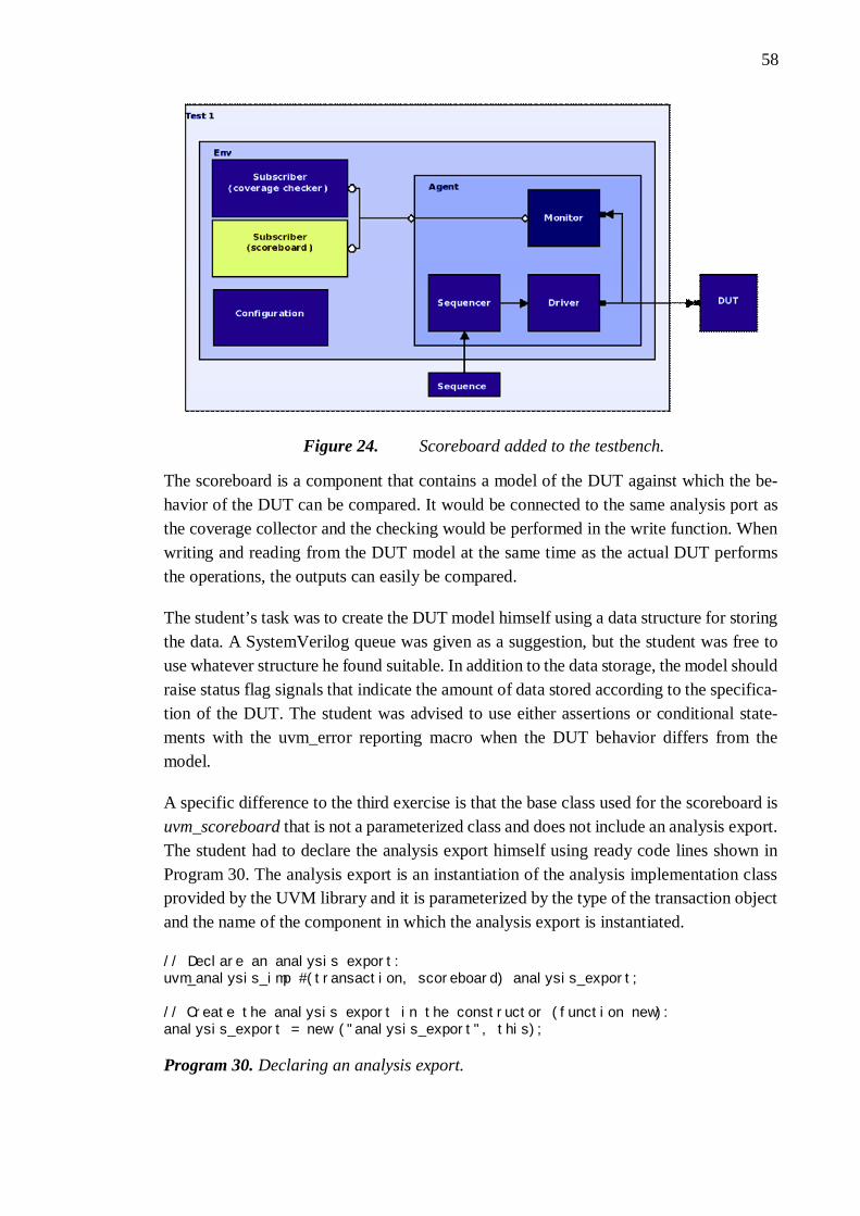
58
Figure 24. Scoreboard added to the testbench.
The scoreboard is a component that contains a model of the DUT against which the be-havior of the DUT can be compared. It would be connected to the same analysis port asthe coverage collector and the checking would be performed in the write function. Whenwriting and reading from the DUT model at the same time as the actual DUT performsthe operations, the outputs can easily be compared.
The student’s task was to create the DUT model himself using a data structure for storingthe data. A SystemVerilog queue was given as a suggestion, but the student was free touse whatever structure he found suitable. In addition to the data storage, the model shouldraise status flag signals that indicate the amount of data stored according to the specifica-tion of the DUT. The student was advised to use either assertions or conditional state-ments with the uvm_error reporting macro when the DUT behavior differs from themodel.
A specific difference to the third exercise is that the base class used for the scoreboard isuvm_scoreboard that is not a parameterized class and does not include an analysis export.The student had to declare the analysis export himself using ready code lines shown inProgram 30. The analysis export is an instantiation of the analysis implementation classprovided by the UVM library and it is parameterized by the type of the transaction objectand the name of the component in which the analysis export is instantiated.
// Declare an analysis export:uvm_analysis_imp #(transaction, scoreboard) analysis_export;
// Create the analysis export in the constructor (function new):analysis_export = new ("analysis_export", this);
Program 30. Declaring an analysis export.

59
After the student had completed the scoreboard and connected it to the environment, thetestbench was ready for directed testing. The sequence could be improved by adding moretransactions and if enough transactions were added, the DUT behavior could be checkedin all cases. However, writing directed tests that check all the corner cases is very labori-ous and not effective even when the DUT is as simple as a FIFO. The amount of transac-tions needed for checking all the usage cases would grow high and it would be easy tomiss some features. Therefore, the next step in the exercise was to extend the testbenchwith randomized sequences.
The student was instructed to create a new sequence that is extended from the basic se-quence used in the exercises. The new sequence should use the randomize method builtinto the transaction object. The declaration of the transaction can specify the signals thatshould be randomized using the rand keyword. When the randomize method is called inthe sequence, the simulator generates random values for those signals. When the sequencecontains a loop that generates new randomized input on every iteration, more corner caseswill eventually be revealed as the amount of iterations is increased. Using a loop in thesequence was not instructed and it had been left for the student to find out, but the assistantcould hint the student to that direction. In addition, the transaction object declarationspecified only some signals to be randomized, and this should be hinted to the student aswell.
Constraints are an additional UVM concept that would aid in randomized testing. Con-straints can be used for example to limit the randomized values as in the first example inProgram 31, or to specify distributions as the second example shows. The distribution inthe second example specifies that the write_enable signal should be high every 10 cycleson average. An information block hinted the purpose and basic syntax for adding con-straints in either the transaction object or in-line in the sequence.
// Base constraints set the values the signal can have:constraint c_data { data >= 0; data < 1024; }
// Constraints can also be used to set distributions. For example:constraint c_we_dist { write_enable dist { 0 := 9 , 1 := 1 }; }
Program 31. Constraint examples.
The student was advised that rather than using the new random sequence in the existingtest, it would be better to declare a new test for the new sequence. This way the directedtest already specified could be still be used without modifying the testbench every timethe user wishes to change the method of testing. A new test, which is extended from theready test_base class, was instructed to be created. The random test inherits the buildphase method, which creates the environment, from the test_base class, and only declaresa different run phase task that uses a different sequence. The build phase task is inheritedby calling super.build_phase method in the build phase. The student should be able todeclare his own test using the test_base class declaration for reference. The final UVM

60
testbench would appear as is shown in the Figure 25. The testbench in the figure has threedifferent tests, each using different sequences.
Figure 25. The final UVM testbench.
Furthermore, an alternative that reuses also the run phase task but replaces the sequenceobject using the UVM factory override system, was provided in an information box. Thetest could specify an override, as shown in Program 32, that changes the type of the se-quence with another one extended from it in the end of elaboration phase that is run afterthe build phase but before the run phase in which the sequence is actually created. This isa more advanced concept of UVM and was not mandatory in the exercises, but the basicusage of the factory overrides was provided as a curiosity.
basic_sequence::type_id::set_type_override(random_sequence::get_type());
Program 32. Override example
As the student had already seen in the first exercise, the name of the test to be run wasspecified in the top-level component of the UVM testbench as a parameter for therun_test method. The instructions told that the name of the test can be changed there, buta better approach would be to leave the parameter of the run_test method empty. Thisway the name of the test to be run can be specified on the command line when startingthe simulation. A variable for the test name has been already included in the make file.
After the exercise, the student should be familiar with all the key concepts of UVM. Hehas created a complete UVM environment using all the basic components and declared aconstrained randomized sequence that is run in a randomized test. He would have expe-rience of creating a high-level model of the DUT in the scoreboard and used the dataprovided by the monitor for automated testing. He would also understand the concept oftests and how they differ from the UVM environment.
61
6.3.5 Exercise 5: Verifying FIFO blocks
The fifth exercise was designed to show the student the UVM testbenches in action. Hewould see himself how the testbench is able to find bugs in incorrect designs.
When starting the fifth exercise, the student should have a complete UVM testbench thatis able to find bugs in misbehaving designs using coverage driven constrained randomizedtesting. So far, the DUT in the exercises had been an error-free FIFO, but in this exercise,the student’s testbench design was used for checking other FIFO designs that introducesmall bugs.
The other FIFO designs had been modified from the error-free FIFO by changing onecode line to behave incorrectly and then the VHDL code was obfuscated. The obfuscationhad been done so that the bugs could not have been easily seen by examining the DUTand the student had to use the UVM testbench for finding them. The code was obfuscatedby replacing all the internal signal and variable names with a single letter and then re-moving all the line breaks.
The student was instructed to find out a single bug in two different FIFO designs. Theerrors might be for example data corruption, incorrect behavior of the status signals, in-correct reset handling or something else. There could be a possibility, that the student’stestbench is not able to find the bugs. In this case, the assistant should point directions forimproving the testbench.
After the exercise, the student should have experience of verification using a UVMtestbench. He would have seen in practice, how the bugs in designs show up in the outputof the testbench and analyzed the output data to discover the source of the problem.
6.3.6 Exercise 6: Verifying the decrypter
Exercise 6 was an introduction to horizontal reuse in UVM. In this exercise, the task wasto create a completely new testbench for the decrypter module designed in the SystemVer-ilog exercises. The student was encouraged to reuse components from the previous exer-cises. The purpose of the exercise 6 was to give students more experience of UVMtestbench design and finishing the exercise would not be crucial for completing the learn-ing objectives of the education. All the learning objectives should have been met in thefirst five exercises. The student had a choice of using his own implementation from theSystemVerilog exercises as the DUT or downloading a working example module.
Because of the diversity in the students’ background it was predicted, that some studentswould have more than enough time to finish this exercise and some would use the threetraining days for the first five exercises. To serve the purpose of giving everyone a suita-

62
ble amount of work the exercise was split in two options. There was a basic and an ad-vanced version of this exercise, and the student was allowed to choose freely betweenthem or if there was enough time, he could finish both of them starting from the basicone.
The aim in exercise 6 basic was to verify the decrypter module with a UVM testbench.The concepts introduced in the first five exercises should be otherwise sufficient for fin-ishing the task, but because the DUT behavior utilizes handshaking signals, the studentwas instructed how the communication could be implemented in UVM. The driver candeliver the DUT’s response back to the sequence for determining the next sequence item,or the sequence can be more abstract and the driver would implement the handshaking byreading the response of the DUT. Both the principles are valid, but the latter would be abetter method because of its higher level of abstraction. Both options were explained tothe student.
The advanced version of the exercise 6 was to verify the decrypter module wrapped insidethe AMBA AXI4-Lite interface wrapper. The UVM environment would be specified withtwo agents. An active agent would drive the AMBA AXI4-Lite interface and a separatepassive one would read the output signals of the DUT. For simplification, the student wasadvised to declare the passive agent so that it contains only a monitor instead of declaringa complete agent with the sequencer and driver switched off, because an active versionof such agent that only interfaces the output signal would never be needed.
In addition, the advanced version of the exercise 6 contained an information block aboutresponse handling. Another hints given for the student contained a suggestion for a designorder in which the base functionality should be done first one agent at the time and thenthe rest of the components are added one by one. The student was also advised to think ifhe needs multiple types of transactions with different levels of abstraction. Another ques-tion was if explicit bins could be practical in the coverage collector for example in thecoverpoint for address signal, because the address in the design can either be valid, invalidbut in the address range of the component or out of the address range and therefore notinteresting. Therefore, covering all the values would not be important.
The horizontal reuse in the exercise was done by modifying the testbench used in the firstfive exercises to be used to verify a completely different design. Not all the componentscould be used in the new testbench directly because of the differences in the DUT signalsand functionality, but the student gained an understanding of how much of the code hadto be rewritten.
After finishing the sixth exercise, either on the basic or the advanced level, the studentshould be able to create his own UVM testbench design without any outside support andto verify his own design using UVM. He knows how the response of the DUT can affectthe signals generated by the driver and what the possibilities are for handshaking signal

63
generation in UVM. Furthermore, the advanced exercise 6 introduced the student to thedifferent roles for multiple agents in a UVM environment.
6.3.7 Exercise 7: Integration level testbench
A final additional work for the fastest performers was an introduction to vertical reusewith an integration level testbench in exercise 7. The student was instructed to examineand run a more complex testbench design including a hierarchy of multiple environments.The purpose of the task was to provide the student an overview of a real UVM system.
The complete testbench was acquired from an example in Verification Academy [18]. Ablock diagram of the complete system is shown in Figure 26. The environment integratesseparate GPIO and SPI block level environments together to form a higher-level periph-eral subsystem environment and adds a passive AHB bus agent. The example testbenchalso utilizes the register abstraction layer of UVM. [18]
Figure 26. The integration level testbench. [18]

64
Both the block level environments could be simulated using block level tests and therewas an additional integration level test for running the complete system. The student’stask was to examine the testbench structure and see how the simulation output appears ondifferent levels. The DUT had bugs, but the task description did not instruct to find cor-rections for them. A student already experienced in digital design could be able to debugthe design using the test output data, but that was not required in the exercise.
The seventh exercise introduced the student to more advanced concepts in UVM and gavean example of real-world use of UVM. The student experienced an integration leveltestbench in action and encountered the use of register abstraction layer. He saw how theenvironments of different levels were encapsulated together and used to run in a higher-level test.

65
7. TRAINING SESSIONS AND RESULTS
The education was divided into two lecture and two training days for SystemVerilog andone lecture and three training days for UVM. Because of the structure of the exercisesand the diversity in student backgrounds, guided exercise sessions were not an option. Allthe training was independent work, where the students were encouraged to discuss witheach other and the assistant was present to answer questions and to help to solve the prob-lems faced.
In the beginning of the first exercise days of SystemVerilog and UVM, the assistantshowed the usage of tools so that everyone could focus more on the exercise tasks andless on the technical problems with the tool usage. If some unusually common problemswere faced, they were discussed together.
7.1 Learning outcomes
Based on visual monitoring, all the students managed to at least start the exercise 4 in theSystemVerilog exercises and at least almost finish the exercise 4 in the UVM exercises.The progress was as was expected and everyone had enough exercises for the whole timewhile no one was in the situation that there was not enough time to learn the most im-portant content.
There was an anonymous survey form for monitoring time usage in each exercise. Thesurvey was not added until the second UVM exercise day, so there is no reliable moni-toring data for SystemVerilog exercises. The students were asked to fill out an estimationlater, but only two of them answered so it was considered that the results would not rep-resent an estimation for the whole population. Therefore, only the data from UVM exer-cises is inspected in this section.
The students were informed to fill out the form after each exercise or in the end of thetraining even though they had not finished the task. The form asked for the exercise num-ber and the time usage rounded to half hours. There was also a checkbox for marking thatthe exercise had been started but not completed and a question if the student worked aloneor in a pair. The Figure 27 shows the completion of each exercise based on the survey.

66
Figure 27. Completion of each exercise.
Based on the answers, it can be seen that not everyone participated in the survey aftereach exercise but those who did, managed at least to start the UVM exercise 4. The oneanswer, where the exercise 4 was not finished, reported that 8 hours were spent on thetask. Based on visual monitoring, more than the 6 people reported were able to start theexercise 6 or 7. The exercise to be started after exercise 5 was the student’s own choice.
The time usage for each exercise is shown in Figure 28. The figure shows the averagetime and the deviation. More data would be required for accurate assumptions, but thechart shows that the difficulty of the exercises increased from exercise 1 to 4. As thedifficulty increased, more time was used on the task and the deviation of the time usageincreased. The more experienced students had fewer difficulties in solving the task.
Figure 28. Time usage in each UVM exercise.
The chart only notices the students who were able to finish the task. As the choice betweenthe exercise 6 and 7 was left for the student, the time usage reporting is divided betweenthese tasks and a small population does not present an actual average. Still it can be seenthat the advanced version of the exercise 6 required significantly more time. The exercise7 did not require specific work to be done, so the students used the remaining time toinspect the integration-level testbench.
0
2
4
6
8
10
12
1 2 3 4 5 6 - basic 6 - advanced 7
completed started
0,0
2,0
4,0
6,0
8,0
10,0
1 2 3 4 5 6 - basic 6 - advanced 7
Tim
e(h
)
Exercise

67
Another observation from the chart is that no task was too overwhelming, although thereports of exercise 4 taking 8 hours, of which one was not able to fully complete the task,should be taken into consideration. The design of the scoreboard was the most time-con-suming part of exercise 4 and the randomization and new test declaration could be sepa-rated to for a new exercise to make the exercises more balanced.
7.2 Student feedback
The training office had feedback forms for the students to fill out twice per module. Thefirst of the forms covered only the first four lecture days of the verification module andsecond one covered all the SystemVerilog and UVM training days and the one UVMlecture day. The students were asked to rate their overall satisfaction and more specificconcerns on a scale of 1 to 5. In addition, there was a change for verbal feedback. Asummary of the numerical feedback to both the feedback forms in the verification moduleis in the Table 5. The students had also an option to answer 6, meaning they were notpresent, to some questions, but that was omitted in the table because it was not availablein all the questions and there were no such answers.
Table 5. Feedback summary.
1 2 3 4 5 Total Mean σPlease rate your overall satisfaction with the training on a scale of 1-5(1 = very dissatisfied, 5 = very satisfied)Overall satisfaction (1/2) 0 2 5 1 1 9 3,11 0,87Overall satisfaction (2/2) 0 0 1 8 0 9 3,89 0,33On a scale of 1-5, please rate how well the intended learning outcomes were addressedduring the training and how well the instructional strategies supported your learning(1 = very poor, 5 = excellent, 6 = I was not present)Learning outcomes (1/2) 0 1 1 5 2 9 3,89 0,97Instructional strategies (1/2) 0 2 3 3 1 9 3,33 1,00In total (1/2) 0 3 4 8 3 18 3,61Learning outcomes (2/2) 0 0 0 7 2 9 4,22 0,44Instructional strategies (2/2) 0 0 6 3 0 9 3,33 0,50In total (2/2) 0 0 6 10 2 18 3,78Please rate the instructors ability to provide you with a deeper understanding of thesubject matter (1 = very poor, 5 = excellent)Trainer A (1/2) 0 2 3 3 1 9 3,33 1,00Trainer B (2/2) 0 0 3 6 0 9 3,67 0,50Trainer A (2/2) 0 0 3 6 0 9 3,67 0,50
The numbers 1/2 and 2/2 in parentheses indicate the feedback form. Trainer A was re-sponsible for the lectures and trainer B for the exercises. Some of the students informedin the comments for the second feedback form that their grade is for the education as awhole and not only the second part. Out of 22 students, 9 returned the feedback form.
68
The results show that the students were more satisfied with the second part of the training,which covered all the exercises. The mixed overall satisfaction during the first lecturepart of the module changed to a solid answer of 4 from almost every participant. In addi-tion, the mean value of learning outcomes improved to a satisfactory level, which meansthat the exercises supported the training module well. The mean opinion on instructionalstrategies remained unchanged between the first and the second feedback form, but thedeviation in the answers decreased.
As it has been pointed out in the verbal comments, the disappointment in instructionalstrategies was only a scheduling issue. Full lecture days without any hands-on experiencebetween lectures can be very overwhelming whatever the subject. Many of the studentspointed out in the verbal feedback, that theory and practice should be mixed more to makethe education easier to follow. These kinds of education modules would be better arrangedand easier to follow if the hands-on training was in shorter sessions between lectures, butthis time it was not an option. The fact was acknowledged before the module, but therewere practical problems with the training room reservations that forced the schedule. Onthe other hand, one student commented that the UVM education schedule with one fulllecture day before practical training was a good choice, because it was easier to start thepractical exercises after all the lectures.
The contents of the training received better feedback, with comments for example “Tar-get was good and contents was well absorbed” and “Good overview on design verifica-tion”. The number of replies to the feedback form was only under a half of the numberof the students and only a half of those who replied provided also verbal feedback.
One of the verbal comments that concerned the exercises and demands the most attentionwas “UVM exercises were better than the SystemVerilog exercises. In SystemVerilog ex-ercises we were required to create design(s) which took me a long time to do.” It is truethat the theme of the education was verification and not design. Still, SystemVerilog is anew language for most of the participants and the design portion was chosen because thatway the students would get a better overview of the whole language, not only the verifi-cation aspects – a verification engineer would have to understand the design portion ofthe language as well. The assistant should have been more active so that everyone wouldhave spent most of the time learning the language, not struggling with design issues. Thisis supported by another verbal comment “I would have preferred more guided sessions,like showing what is a correct way to do the exercises after a while.” The situation washelped by providing the students with example solutions via e-mail after the training ses-sions, but discussing good testbench design principles in the classroom would have beena good addition.
The only verbal feedback about the performance of the assistant responsible for the train-ing sessions was “The assistant could've been more resourceful, and practical experience

69
on larger test environments was missing. Not able to answer all questions.” More prac-tical experience on UVM would have helped a lot to provide the students with additionalknowledge outside the scope of the exercises.
The structure of the exercises, especially the UVM part, received acclaim. To the ques-tions “What did you find most valuable and helpful during the training in terms of yourprofessional growth?” and “Do you have any additional feedback or comments that youwould like to share?” one student commented that building the UVM testbench in stepshelped to understand the general picture and two of them pointed out how the tasks pro-gressed well from aided copying to more realistic ones. The amount of information pro-vided seems to have been correct in all the exercises.
Overall, the practical training seems to have been the most educating part of the educationmodule, as it was planned. The exercises were challenging enough but still not too hardto follow. Out of nine responses to the feedback form, eight answered that they wouldrecommend this training to others. Still, because no one was completely satisfied there isa room for improvement if the same training was arranged for a second time. The mostcritical improvement would be to mix the lectures and exercises more.
7.3 Problems faced
Along the exercises, it became clear that some tasks were not declared clear enough inthe exercise instructions. The biggest problems the students faced were mostly simplethings in the first SystemVerilog and UVM exercises when the amount of new infor-mation was most overwhelming. Making an exercise instruction is always balancing be-tween systematic instructions and encouraging student’s own thought process, and thefinal balance can best be achieved with experience. In the beginning when everything isnew information even simple things can seem very complex, and when the student hassome experience already, too thorough instructions can lead to following and copyingthem blindly without any learning.
In SystemVerilog exercises, when the task was to model the functionality of asynchro-nous adder, many had problems understanding the concatenation hints and did an unnec-essarily complex solution, where they for example generated the carry signal with condi-tional clauses. However, the hints provided were only a suggestion of the simplest ap-proach and because the main purpose of the exercise was to get familiar with the syntax,the exercise was more rewarding than it was designed to be.
A bigger fault in the SystemVerilog exercises was the AMBA AXI 4 Lite specificationin the exercise 4. A picture depicting the timing of transactions would have helped tounderstand the specification much better and the incomplete description led to diversityin solutions. The picture was added later, but many of the students had done the exercisealready by then so they were allowed to use whatever solution they had found. After all,

70
the main purpose of the exercise was not to understand clearly the whole AMBA AXIspecification but train to make their own design following outside guidelines and a mis-understanding caused by an incomplete specification still requires the same thought pro-cess in design.
When learning a new programming language, step-by-step guides with single code linesto copy one by one give the correct syntax but complete example codes would aid inunderstanding the structure. Even a relatively simple complete code file that performssome completely different operation but shows the correct structure would help to clarifywhich code block goes where, when the language is unfamiliar. This was realized after asuggestion from a student during SystemVerilog exercises and answered by creating ex-ample codes with different designs during exercise session breaks. Links to the examplecode files were added to information boxes in exercise instructions. The added examplecodes were for simple simulation testbenches in exercise 1 and state machines in exercise2. The problem only existed in SystemVerilog exercises, because the UVM exercises al-ready had complete code files for reference.
In UVM exercises surprisingly many used a completely new handle for their first owntransaction in exercise 1. Using a new handle for every transaction is not feasible in real-world solutions because the amount of handles will grow massive, and this was explainedto the students. This was a good example of simple errors caused by an overwhelmingamount of new information.
There was a small error in the preconfigured driver component of the UVM testbench thatcaused additional thinking work. The retrieval of a sequence item from the sequencer wasdone after waiting for a rising clock edge on which the sequence item should be trans-formed into pin activity in the DUT. Because the communication between the driver andthe sequencer introduces a small delay and the monitor component done by the studentsin exercise 2 had no such delays, the monitor managed to read the state of the DUT’ssignals before the driver wrote new values to the input pins. Although both the compo-nents were working on the same clock cycle, the monitor output seemed to arrive oneclock cycle later. The proper order of activity in the driver would be to first get the se-quence item from the sequencer and then write the information to the DUT directly afterthe clock edge.
This problem was particularly exciting and the reason and fix for it was explained to thestudents during the training sessions. It was agreed with the lecturer, that if the exerciseswere reused later on another course, the problem should be left unfixed but documentedfor the course staff and then introduced later in the exercises. This way the students willsee concretely how crucial the timing of the transactions really is.
The colors used in the exercise instructions were a surprising source of puzzlement. Therewas a large diversity in the brightness and gamma curves of the monitors in the class and

71
this lead to the situation where some students had difficulties to distinguish the coloredinfo and code blocks from body text, because on some computers all the text had whitebackground. The class monitors should have been calibrated and tested one by one or thecolor scheme should have been chosen more carefully to prevent this.
If these exercises were used later, a big improvement would be to tie the UVM exercisesto a verification plan done by the students themselves before the exercises. This time theschedule did not allow concentrating on the verification plan otherwise than on lecturelevel, but planning which DUT features have to be tested and where to focus most wouldbe educating. In addition, the improved specification for the design in SystemVerilogexercise 3, that the student has made according to the results of validation and verifica-tion, should be returned for examination.
72
8. CONCLUSIONS
The objective in this thesis was to design an effective exercise package that could be usedin training of new verification engineers. The exercises would introduce the student to theSystemVerilog language and UVM methodology. The target was to cover key conceptsof SystemVerilog both in design and verification perspective and to provide the studentwith understanding of UVM so that the he would be able to design a complete UVMtestbench using the common UVM components and methods by himself after the training.The amount of exercises was decided so that every student should have time to learn themost important content but a sufficient amount of additional exercises was provided forthe fastest performers.
The planned exercise package was tested in a tailored education module arranged for acompany. The exercises were implemented as independent work during five training daysso that the assistant was present to answer questions and to help in problem solving. Theresults were monitored with a time usage survey and a feedback form that had an optionof verbal feedback.
The time usage survey and visual monitoring during the exercise sessions showed thatthe learning objectives were fulfilled during the training and the difficulty level of theexercises was as planned. Every student managed to finish the most important content butmany had time to proceed to the advanced tasks.
The students were also quite satisfied with the content and structure of the exercises ac-cording to the feedback. The verbal feedback praised the aspects that were most focusedon when planning the exercises, especially progression from aided copying to tasks thatdemanded more thought process while still providing all the syntax help. On the otherhand, they criticized all the problems that were known beforehand, mainly the division oflecture and exercise days during the training module so that the hands-on training oc-curred after multiple consecutive lecture days.
Overall, the exercise packet is considered ready for further use based on the experiencesgained during the implementation of the training module, when little corrections havebeen done. The noted corrections were minor clarity issues in the exercise instructions.One of the further uses for the exercises could be a new verification course at TampereUniversity of Technology, as the demand for verification engineers will continue to in-crease and the previous verification course has not been arranged after 2013.

73
REFERENCES
[1] Accellera Systems Initiative Delivers UVM 1.2 to IEEE for Standardization, Ac-cellera Systems Initiative, 2015. Available (accessed on 23.11.2016):http://www.accellera.org/news/press-releases/201-accellera-systems-initiative-de-livers-uvm-1-2-to-ieee-for-standardization
[2] Members, Accellera Systems Initiative, 2016. Available (accessed on23.11.2016): http://accellera.org/about/members
[3] Universal Verification Methodology (UVM) 1.2 Class Reference, Accellera Sys-tems Initiative, 2014, 929 p. Available (accessed on 23.11.2016): https://verifica-tionacademy.com/verification-methodology-reference/uvm
[4] Universal Verification Methodology (UVM) 1.2 User’s Guide, Accellera SystemsInitiative, 2015, 184 p. Available (accessed on 23.11.2016): http://www.accel-lera.org/images/downloads/standards/uvm/uvm_users_guide_1.2.pdf
[5] G. Allan, M. Baird, R. Edelman, A. Erickson, M. Horn, M. Peryer, A. Rose, K.Schwartz, UVM Cookbook, Mentor Graphics, 2013, 591 p. Available (accessedon 23.11.2016): https://verificationacademy.com/cookbook/uvm
[6] T. Alsop, VIP TSC Standardization Update, Accellera Systems Initiative, 2010.Available (accessed on 23.11.2016): http://www.accellera.org/images/activi-ties/committees/uvm/VIP-TC_standard_effort_update_Jan_2010.pdf
[7] AMBA® AXI™ and ACE™ Protocol Specification, ARM, 2011.
[8] M. Bartley, Migrating to UVM: how and why! 2010. Available (accessed on23.11.2016): https://www.testandverification.com/wp-content/uploads/mike_bart-ley_snug_reading_2010.pdf
[9] J. Bergeron, E. Cerny, A. Hunter, A. Nightingale, Verification Methodology Man-ual for SystemVerilog, Springer, 2006, 503 p.
[10] J. Bergeron, Writing Testbenches: Functional Verification of HDL Models, Sec-ond Edition, Springer, 2003, 182 p.
[11] H. Foster, Prologue: The 2016 Wilson Research Group Functional VerificationStudy, Mentor Graphics, 2016. Available (accessed on 23.11.2016):https://blogs.mentor.com/verificationhorizons/blog/2016/08/08/prologue-the-2016-wilson-research-group-functional-verification-study/
[12] H. Foster, Trends in Functional Verification: A 2014 Industry Study, MentorGraphics, 2014.

74
[13] IEEE 1364-2005 Standard for Verilog® Hardware Description Language, Insti-tute of Electrical and Electronics Engineers (IEEE), 2005.
[14] IEEE 1800-2005 Standard for SystemVerilog – Unified Hardware Design, Speci-fication, and Verification Language, Institute of Electrical and Electronics Engi-neers (IEEE), 2005.
[15] IEEE 1800-2009 Standard for SystemVerilog – Unified Hardware Design, Speci-fication, and Verification Language, Institute of Electrical and Electronics Engi-neers (IEEE), 2009.
[16] IEEE 1800-2012 Standard for SystemVerilog – Unified Hardware Design, Speci-fication, and Verification Language, Institute of Electrical and Electronics Engi-neers (IEEE), 2012.
[17] A. B. Mehta, SystemVerilog Assertions and Functional Coverage, Springer, 2014,356 p.
[18] Verification Academy, Testbench/IntegrationLevel, Mentor Graphics, 2013.Available (accessed on 23.11.2016): https://verificationacademy.com/cook-book/testbench/integrationlevel
[19] C. Spear, SystemVerilog for Verification, Springer, 2006, 301 p.
[20] J. Virtanen, SystemC Exercise, Tampere University of Technology, 2015. Availa-ble (accessed on 23.11.2016): http://www.tkt.cs.tut.fi/training/edutech2015/Sys-temC-koulutus/ex.html