implementation of wifire mac protocol - iit bombaysri/students/ranjith-thesis.pdf · ·...
TRANSCRIPT

Implementation of WiFiRe MAC protocolRanging, Registration and Packet classifier modules
A thesis submitted in partial fulfillment of
the requirements for the degree of
Master of Technology
by
Madalapu Ranjith Kumar
(Roll No. 05329R08)
Under the guidance of
Prof. Sridhar Iyer
and
Prof. Anirudha Sahoo
DEPARTMENT OF COMPUTER SCIENCE & ENGINEERING
INDIAN INSTITUTE OF TECHNOLOGY–BOMBAY
2008

Dissertation Approval Sheet
This is to certify that the dissertation entitled
Implementation of WiFiRe MAC protocolby
Madalapu Ranjith Kumar
(Roll no. 05329R08)
is approved for the degree ofMaster of Technology.
Prof. Sridhar Iyer
(Supervisor)
Prof. Anirudha Sahoo
(Co-Supervisor)
Prof. Varsha Apte
(Internal Examiner)
Dr. Vijay Raisinghani
(External Examiner)
Prof. T.K. Biswal
(Chairperson)
Date:
Place:

INDIAN INSTITUTE OF TECHNOLOGY BOMBAYCERTIFICATE OF COURSE WORK
This is to certify thatMr. Madalapu Ranjith Kumar was admitted to the candidacy of
the M.Tech. Degree and has successfully completed all the courses required for the M.Tech. Pro-
gramme. The details of the course work done are given below.
Sr.No. Course No. Course Name Credits
Semester 1 (Jul – Nov 2005)
1. HS699 Communication and Presentation Skills (P/NP) 4
2. IT601 Mobile Computing 6
3. IT605 Computer Networks 6
4. IT619 IT Foundation Lab 8
5. IT623 Foundation course of IT - Part II 6
Semester 2 (Jan – Apr 2006)
6. CS681 Performance Analysys of Computer Systems and Network 6
7. IT620 New Trends in Information Technology 6
8. IT625 ICT for Developing Countries 6
Semester 3 (Jul – Nov 2006)
9. IT610 Quality of Sevice in Networks 6
10. IT628 Information Technology Project Management 6
11. IT680 Systems Lab 6
12. IT694 Seminar 4
Semester 4 (Jan – Apr 2007)
13. EE701 Introduction to MEMS 6
Semester 5 (Jul – Nov 2007)
14. CS601 Algorithms and Complexity 6
M.Tech. Project
15. IT696 M.Tech. Project Stage - I (Jul 2007) 18
16. IT697 M.Tech. Project Stage - II (Jan 2008) 30
17. IT698 M.Tech. Project Stage - III (Jul 2008) 42
I.I.T. Bombay Dy. Registrar(Academic)
Dated:
ii

Abstract
WiFiRe is an extension of the existing WiFi protocol for providing broadband access for rural
areas. It provides good bandwidth at ow cost by making use of licence free spectrum at 2.4GHz
band and also cost effective chipsets of WiFi (PHY). It mainly replaces the MAC of existing
WiFi (802.11b) with a MAC of WiMAX (802.16). It follows Time Division Duplex-Multi
Sector TDM (TDD-MSTDM) which uses same channel for both UL (up-link) and DL (down-
link). It has star topology, and divides whole area into sectors; each sector has one base station
(BS) with sectorized antenna, each village has one subscriber terminal (ST) with directional
antenna and a System (S) located at fiber Point-of-Presence (PoP), which controls the whole
network. WiFiRe has one single MAC for all sectors (PHY) in the System, which helps to
co-ordinate the medium access.
Design of WiFiRe MAC was started last year and emulation overEthernet was proposed.
We implemented most of the functionalities for single sector WiFiRe MAC. Implementation
is done using C sockets and it allows user to test basic MAC functions such as connection
establishment, packet flow and header construction, in absence of WiFiRe hardware. Our code
can be easily ported onto hardware. Our implementation supports various kind of applications
like HTTP, FTP, VoIP etc. for Single BS, multiple SubscriberTerminals (ST) and their clients.
Challenges encountered in implementation and their solutions are covered as well.
iii
Contents
Abstract iii
List of Tables vii
List of Figures viii
Abbreviations and Notations viii
1 Introduction and Motivation 1
1.1 Architecture . . . . . . . . . . . . . . . . . . . . . . . . . . . . . . . . . . . . 2
1.2 Motivation . . . . . . . . . . . . . . . . . . . . . . . . . . . . . . . . . . . . . 3
1.3 Problem statement . . . . . . . . . . . . . . . . . . . . . . . . . . . . . . . .3
1.4 Thesis Outline . . . . . . . . . . . . . . . . . . . . . . . . . . . . . . . . . . .4
2 Literature Survey 6
2.1 Long Range WiFi projects . . . . . . . . . . . . . . . . . . . . . . . . . . .. 6
2.2 Overview of WiMAX . . . . . . . . . . . . . . . . . . . . . . . . . . . . . . . 7
2.3 Overview of WiFi . . . . . . . . . . . . . . . . . . . . . . . . . . . . . . . . . 9
3 WiFiRe Protocol 11
3.1 Network Initialization . . . . . . . . . . . . . . . . . . . . . . . . . . .. . . . 11
3.2 MAC Overview . . . . . . . . . . . . . . . . . . . . . . . . . . . . . . . . . . 12
3.3 Framing Structures . . . . . . . . . . . . . . . . . . . . . . . . . . . . . . .. 13
3.3.1 Basic MAC PDU . . . . . . . . . . . . . . . . . . . . . . . . . . . . . 13
3.3.2 MAC Headers . . . . . . . . . . . . . . . . . . . . . . . . . . . . . . 14
3.4 Bandwidth Request grants and Service classes . . . . . . . . .. . . . . . . . . 14
3.4.1 Service classes . . . . . . . . . . . . . . . . . . . . . . . . . . . . . . 14
iv
3.4.2 Type of Grants . . . . . . . . . . . . . . . . . . . . . . . . . . . . . . 15
4 WiFiRe Design and Implementation Overview 16
4.1 Design Overview . . . . . . . . . . . . . . . . . . . . . . . . . . . . . . . . . 16
4.1.1 Real System Components . . . . . . . . . . . . . . . . . . . . . . . . 16
4.1.2 Proposed solution for reducing PHY overhead . . . . . . . .. . . . . 17
4.1.3 Assumptions made on PHY board . . . . . . . . . . . . . . . . . . . . 18
4.2 Implementation Overview . . . . . . . . . . . . . . . . . . . . . . . . . .. . 19
4.2.1 LAN emulation . . . . . . . . . . . . . . . . . . . . . . . . . . . . . . 19
4.2.2 Testbed setup . . . . . . . . . . . . . . . . . . . . . . . . . . . . . . . 20
4.2.3 GPSS mode . . . . . . . . . . . . . . . . . . . . . . . . . . . . . . . . 21
4.3 Modules at BS and ST . . . . . . . . . . . . . . . . . . . . . . . . . . . . . . 22
5 WiFiRe Implementation Modules 25
5.1 Threads, Buffers, Sockets and their interaction . . . . . .. . . . . . . . . . . . 25
5.2 Timer Management . . . . . . . . . . . . . . . . . . . . . . . . . . . . . . . . 27
5.3 CID generator . . . . . . . . . . . . . . . . . . . . . . . . . . . . . . . . . . . 27
5.4 Packet Controller . . . . . . . . . . . . . . . . . . . . . . . . . . . . . . . .. 28
5.4.1 DLTB construction . . . . . . . . . . . . . . . . . . . . . . . . . . . . 29
5.5 Packet classifier . . . . . . . . . . . . . . . . . . . . . . . . . . . . . . . . .. 29
5.5.1 Management packet handler . . . . . . . . . . . . . . . . . . . . . . .29
5.5.2 Data packet handler . . . . . . . . . . . . . . . . . . . . . . . . . . . . 32
5.6 Tables . . . . . . . . . . . . . . . . . . . . . . . . . . . . . . . . . . . . . . . 33
5.7 Filters and Stats display . . . . . . . . . . . . . . . . . . . . . . . . . .. . . . 35
5.8 Config file and IO Debug levels . . . . . . . . . . . . . . . . . . . . . . . .. . 36
6 Experiments and Learnings 40
6.1 Experiments conducted . . . . . . . . . . . . . . . . . . . . . . . . . . . .. . 40
6.1.1 Within same ST . . . . . . . . . . . . . . . . . . . . . . . . . . . . . . 40
6.1.2 Between different STs . . . . . . . . . . . . . . . . . . . . . . . . . . 41
6.2 Learnings . . . . . . . . . . . . . . . . . . . . . . . . . . . . . . . . . . . . . 42
6.2.1 ARP Cache Flush . . . . . . . . . . . . . . . . . . . . . . . . . . . . . 42
6.2.2 Moving from 32 bit to 64 bit machine . . . . . . . . . . . . . . . . .. 43
v
6.2.3 Problem with RTP packets . . . . . . . . . . . . . . . . . . . . . . . . 44
6.2.4 Problem with Non-WiFiRe packets in WiFiRe network . . .. . . . . . 44
6.2.5 Problem with multiple DHCP servers . . . . . . . . . . . . . . . .. . 45
6.2.6 Memory Management Unit . . . . . . . . . . . . . . . . . . . . . . . . 45
6.2.7 Soft timer limitation . . . . . . . . . . . . . . . . . . . . . . . . . . .46
7 Conclusions and Future Work 47
7.1 Conclusions . . . . . . . . . . . . . . . . . . . . . . . . . . . . . . . . . . . . 47
7.2 Future work . . . . . . . . . . . . . . . . . . . . . . . . . . . . . . . . . . . . 47
Appendix 49
A Other required software configurations 49
Bibliography 52
Publications 54
Acknowledgement 56
vi

List of Tables
5.1 ST-TABLE at ST; used for storing Client details at ST . . . .. . . . . . . . . . 34
5.2 ST-MAPPER at BS; used for mapping between ST and BS . . . . . .. . . . . 34
5.3 BS-TABLE at BS; used for storing Client details at BS . . . .. . . . . . . . . 34
5.4 Config.wre:Different configuration variables and their default values. . . . . . 37
5.5 Debug Levels . . . . . . . . . . . . . . . . . . . . . . . . . . . . . . . . . . . 39
vii

List of Figures
1.1 WiFiRe system architecture[1] . . . . . . . . . . . . . . . . . . . . .. . . . . 2
1.2 WiFiRe system architecture, Multi-sector system . . . . .. . . . . . . . . . . 2
1.3 Division of work, WiFiRe MAC modules . . . . . . . . . . . . . . . . .. . . 5
3.1 Basic communication sequence diagram[1] . . . . . . . . . . . .. . . . . . . 11
3.2 Medium Access Control (MAC) mechanism and Timing sequence of WiFiRe[1] 13
3.3 MAC PDU format . . . . . . . . . . . . . . . . . . . . . . . . . . . . . . . . . 13
3.4 Generic MAC header . . . . . . . . . . . . . . . . . . . . . . . . . . . . . . . 14
3.5 Beacon header . . . . . . . . . . . . . . . . . . . . . . . . . . . . . . . . . . . 14
4.1 BS hardware: proposed WiFiRe real system component [5] .. . . . . . . . . . 17
4.2 Consecutive allocation of DL slots for each BS [4] . . . . . .. . . . . . . . . 18
4.3 WiFiRe Test Bed . . . . . . . . . . . . . . . . . . . . . . . . . . . . . . . . . 20
4.4 Block diagram for BS . . . . . . . . . . . . . . . . . . . . . . . . . . . . . . .22
4.5 Block diagram for ST . . . . . . . . . . . . . . . . . . . . . . . . . . . . . . .23
5.1 Sockets, Buffers, Threads and Ethernet interfaces . . . .. . . . . . . . . . . . 25
5.2 CID format . . . . . . . . . . . . . . . . . . . . . . . . . . . . . . . . . . . . 28
5.3 Packet flow in Packet classifier module . . . . . . . . . . . . . . . .. . . . . . 30
5.4 Beacon Message . . . . . . . . . . . . . . . . . . . . . . . . . . . . . . . . . 30
5.5 Sequence of steps at ST when it receives responses from BS. . . . . . . . . . 31
5.6 Sequence of steps at BS when it receives new request from ST . . . . . . . . . 32
5.7 WiFiRe Statistics screenshot (GUI) . . . . . . . . . . . . . . . . .. . . . . . . 36
5.8 List of red Config values and Menu commands . . . . . . . . . . . . .. . . . 38
6.1 Final Single sector Testbed used for experiments . . . . . .. . . . . . . . . . 41
viii

Abbreviations and Notations
ARP : Address Resolution Protocol
BE : Best Efforts
BS : Base Station
BSID : Base Station Identification
BWA : Broadband Wireless Access
CID : Connection Identifier
CRC : Cyclic Redundancy Code
CS : Carrier Sense
CSMA : Carrier Sense Multiple Access
DCF : Distributed Co-ordination Function
DCID : Data Connection Identifier
DBPSK : Differential Binary Phase Shift Keying
DL : Down Link
DL-MAP : Down Link Slot Allocation Map
DLL : Data Link Layer
DQPSK : Differential Quadratic Phase Shift Keying
DSA : Dynamic Service Addtion
DSSS : Direct Sequence Spread Spectrum
DL-TB : Down Link Transport Block
FTP : File Transfer Protocol
GPC : Grant Per Connection
GPSF : Grant Per Service Flow Type
GPST : Grant Per Subscriber Terminal
ix

HTTP : Hyper Text Transfer Protocol
ID : Identifier
IP : Internet Protocol
LAN : Local Area Network
LoS : Line of Sight
MAC : Medium Access Control layer
MTU : Maximum Transmission Unit
NIC : Network Interface Card
nrtPS : Non-real Time Polling Service
PCF : Point Co-ordination Function
PDU : Protocol Data Unit
PHY : Physical Layer
PoP : Point of Presence
PS : Physical Slot
QoS : Quality of Service
rtPS : Real Time Polling Service
RF : Radio Frequency
Rx : Reception
S : System
SAP : Service Access Point
SDU : Service Data Unit
SF : Service Flow
SS : Subscriber Station
ST : Subscriber Terminal
TCP : Transmission Control Protocol
TDD : Time Division Duplex
TDM : Time Division Multiplex
TDMA : Time Division Multiple Access
Tx : Transmission
UDP : User Datagram Protocol
UE : User Equipment
UGS : Unsolicited Grant Service
x

UL : Up Link
UL-MAP : Up Link Slot Allocation Map
UL-TB : Up Link Transport Block
URL : Universal Resource Locater
VoIP : Voice over IP
WAN : Wide Area Network
WiFi : Wireless Fidelity
WiFiRe : Wireless Fidelity for Rural Extension
WiMAX : Worldwide Interoperability for Microwave Access
xi

Chapter 1
Introduction and Motivation
Now-a-days the use of Internet and mobile communication hasgrown to a large extent such that
it became mandatory for daily usage of life. The statistics in India show that there are more
than 100 million mobile users in India [as per June 10th, 2005], which show its importance in
daily routine. Major population in India resides in remote areas where access to communication
technologies like telephony, Internet etc., are difficult to provide. Broadband Wireless Access
(BWA) is the best way to meet escalating business demand for rapid Internet connection and
integrated data, voice and video services. But deployment of BWA (WiMAX) compatible de-
vices is much complex and costlier. Rural areas are sparselypopulated and their distance varies
in few kilometers, unlike urban areas. Installation of morebase stations will probably not solve
this problem, which also costs more.
Wireless Fidelity - Rural Extension (WiFiRe)[1] introduces the concept of wireless com-
munication over WiFi IEEE 802.11b physical layer (PHY)[16]and WiMAX IEEE 802.16 MAC
layer[17]. 802.11b PHY has better availability of low cost chip sets which can operate on unli-
censed 2.4GHz frequency band and WiMAX has potential to communicate over larger distances
of 30-40km range. In India, almost every rural area has land line connection, but mobile com-
munication and broadband are difficult to deploy using land line. We believe, WiFiRe is the
one of the good solution to achieve this goal at affordable cost. WiFiRe supports maximum of
25Mbps data rate, includes both UL and DL, and two parallel transmissions by opposite sectors.
1

Figure 1.1: WiFiRe system architecture[1]
Figure 1.2: WiFiRe system architecture, Multi-sector system
1.1 Architecture
WiFiRe uses a star topology network as shown in above Figure 1.1 and Figure 1.2, in which
System (S) is located at fiber Point-of-Presence (PoP) on topof 40m tower and is connected to
set of Base Stations (BS) which is equivalent to number of sectors in the System. Each BS is
connected to sectorized antenna through which a SubscriberTerminal (ST) is communicated.
Each village holds one ST with 10m directional antenna directing to BS. Each ST differ by 2-
2

3km and all Clients under same ST are connected through LAN. All BS in the System use same
WiFi channel for communication with respected STs, so transmission by one BS may interfere
with adjacent sectors. For avoiding interference between two BSs, only opposite sectors should
communicate parallel. WiFiRe follows TDD-MSTDM approach to communicate with in the
System. Sectorization of coverage area while using the samefrequency channel for all sectors
is a key feature in WiFiRe.
1.2 Motivation
There are alternatives present for broadband wireless access but most of them are not cost ef-
fective. WiMAX-d (IEEE 802.16d), can provide an alternate solution as it has got high gain and
a good spectral efficiency, which can carry 80Mbps over-the-air per base station with a 20MHz
allocation[17]. The main drawback is, deployment requirescomplex and costly hardware that
is not available easily. WiFi (IEEE 802.11b) can provide forshort distance communication of
about few meters but not for long distances. In 802.11 based networks, contention algorithms
such as Distributed Coordination Function (DCF) mechanismdoes not provide any delay guar-
antees and are more distributed in nature, while the Point Coordination Function (PCF) mech-
anism is efficient only for small number of nodes[16]. 802.11based Mesh Network, where it
doesn’t use the existing CSMA/CA technology, instead uses 2-phase TDMA based protocol.
But the problem with 802.11b MAC is its non capability of providing any Quality of Service
(QoS) except PCF. The outdoor long-distance use of 802.11 requires a revisit to the protocols at
various layers of the OSI stack, as well as various system design issues. And finally, our Mobile
cellular technologies cannot provide broadband services with high bandwidth. The concept of
WiFiReseems to be good solution for this scenario and can satisfy bandwidth need at proper
price that suits rural people.
1.3 Problem statement
The main problem that we are focusing here is to replace the MAC layer of the existing WiFi
protocol which is of low cost and easily available PHY chipset with WiMAX like MAC which
have capable of long range communication. In India our protocol works because there are
very few high buildings in the terrain for several kilometers, we can achieve good Line-of-
3

Sight (LoS). WiFi has increased tremendously and it has got the benefit of last-hop wireless
solution in almost all the networks. Basically 802.11 has been designed for indoor operations
but because of its low cost of PHY it is now being taken into consideration for extending to
rural environment.
WiFiRe is promoted by CEWiT India1 and the project is spread across IIT Bombay, IIT
Madras and IISc Bangalore. This project is divided into three major parts each part is handled
by different group. Design of MAC, PHY fabrication and Scheduler are taken care by IITB,
IITM and IISc respectively.
This project started last year by WiFiRe team at IIT Bombay [4][5]. The team has done
theoretical study of protocol, suggested some of the important changes in WiFiRe draft which
helped during the actual implementation. They have also implemented testbed prototype for
emulation which include single ST and BS machines.
Scope of this thesis is to implement MAC specification for theWiFiRe single sector which
includes several modules related to MAC like beaconing, connection management (Ranging or
Registration), handling different CIDs, building frame, basic scheduling, buffer and memory
management, packet encapsulation, packet classification and also supporting documents which
help in further development of the protocol. Primary goal isto provide VoIP (Voice Over IP)
and web connectivity with in a single sector having one BS, multiple ST’s in it and multiple
Clients under each ST.
WiFiRe MAC team work is divided in two parts as shown in Figure1.3. Modules which
are developed by Janak [2] are in grey color while modules developed by Ranjith (me) are
in white color. In this report, we discuss all the modules shown in white color. All modules
integrate with each other and make complete WiFiRe MAC prototype.
1.4 Thesis Outline
The outline of thesis is as follows:
Chapter 2 explains some similar projects which are working to provide long-range com-
munication by using off-the-shelf 802.11 chipset. Detail description of protocol to be imple-
mented is explained in chapter 3. Chapter 4 describes overview of implementation of WiFiRe,
1The Center of Excellence in Wireless Technology (CEWiT) is an independent research organization set up by
the Ministry of Information Technology, Government of India (MIT) in partnership with industry.
4
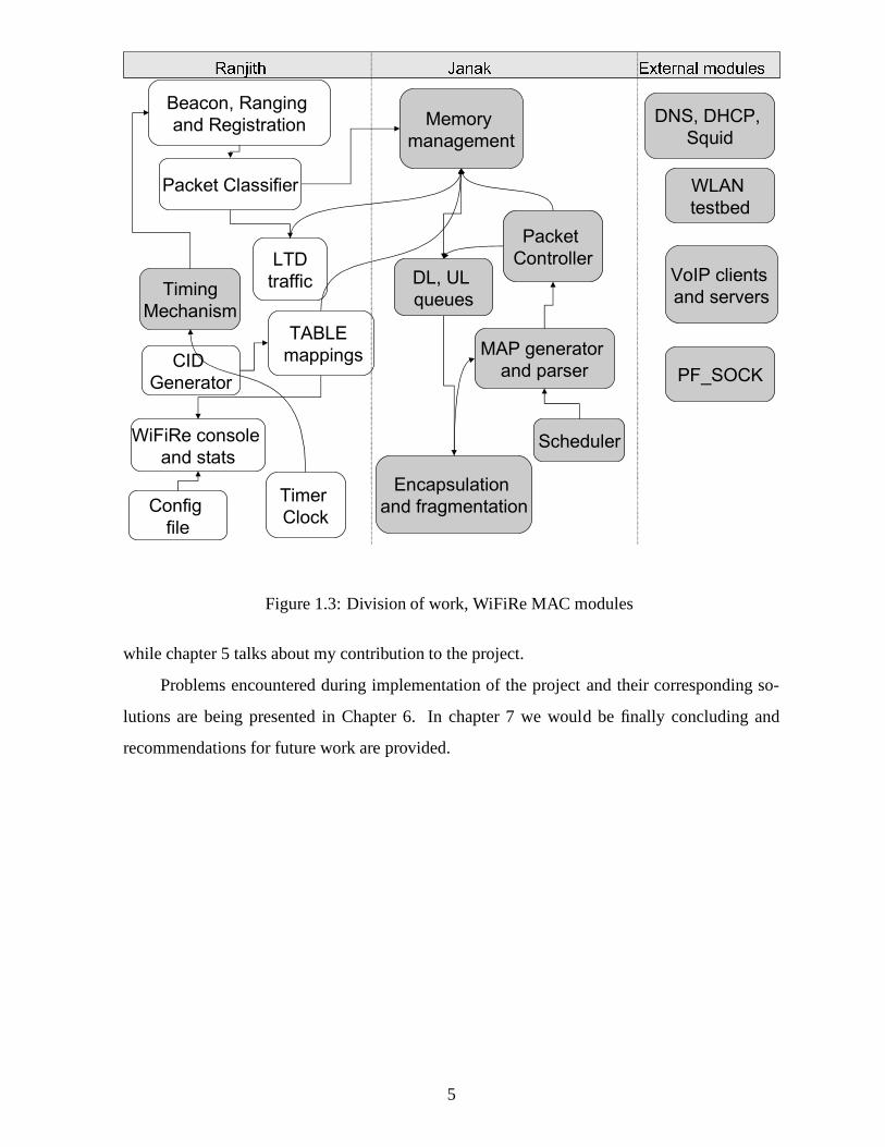
Figure 1.3: Division of work, WiFiRe MAC modules
while chapter 5 talks about my contribution to the project.
Problems encountered during implementation of the projectand their corresponding so-
lutions are being presented in Chapter 6. In chapter 7 we would be finally concluding and
recommendations for future work are provided.
5

Chapter 2
Literature Survey
This chapter covers related work of WiFiRe MAC layer protocol which includes some of the
other similar projects working for long-range communication by using 802.11 chipset, overview
of WiMAX [17] and WiFi [16].
2.1 Long Range WiFi projects
This section is dealt with introduction of few projects which are going on in India as well as all
over the world, in similar area for providing long-range communication by using off-the-shell
802.11 chipset.
Digital Gangetic Plains (DGP) project
Digital Gangetic Plains (DGP) project is started with the aim of providing low cost long range
communications for covering low-density rural areas by using 802.11 chipset at IIT Kanpur[12].
DGP main goals are (a) Quantify 802.11 performance in outdoor (b) Range extension and (c)
Cost reduction. This project has a testbed consisting of multi-hop directional 802.11 links,
testbed span up to 80 km long. 8 hops are located in the testbedwith maximum distance be-
tween point-to-point link is about 38km. Most of the long distance links are over flat terrain
which helps to solve LoS problem. Each hop is located on towerof length about 40m. Each
hop includes off-the-shelf parabolic grid antennas for directional gain and off-the-shelf 802.11b
Access-Points(APs) at each hop location. The APs are operated in bridge-mode. Several chal-
lenges relating to Physical layer, MAC layer, routing and reconfigurable issues are discussed in
[12]. DGP follows Spatial-reuse TDMA (STDMA) scheduling for communication. STDMA
6
means, scheduling the various links of the network for transmission, taking into account what
simultaneous transmissions, or spatial-reuse is possible.
Low-cost WiFi-based Long Distance (WiLD) networks
WiFi-based Long Distance (WiLD) project is started with aimproviding new appropriate wire-
less technologies that can provide low-cost, rapidly deployable connectivity solutions for low
user-density regions[6]. WiLD project deployed testbeds in India (a 9-link topology), Ghana
(5link) and San Francisco Bay area in US (7 link). WiLD testbed consists of multi-hop nodes
with high gain antennas. They used low-cost electronicallysteerable antennas to avoid mis-
alignment due to environmental effects like wind etc. Distance covered by WiLD network vary
from 10-80km. It is LoS deployment, but relays are installedwhere there is no LoS. Some of
the challenges described in [6] are (a) MAC layer issues; like ACK time out, collisions due to
bidirectional traffic and Multi-link interference, (b) Loss recovery; done using retransmission
with Bulk ACKs, (c) QoS Provisioning issues, (d)trouble shooting; reconfigurable and man-
agement issues, (e) Network planing and deployment issues.WiLD uses sliding-window based
flow-control approach with the TDMA slots. For supporting simultaneous transmit and receive
it uses TDMA slot scheduling.
2.2 Overview of WiMAX
WiMAX is World wide Interoperability for Microwave Access.It is 802.16 Air Interface
Standard[17]. For a Point-to-Multipoint (PMP) topology, acontrolling base station (BS) con-
nects multiple subscriber stations (SS) to various public networks. The standard defines a con-
nection oriented MAC protocol, and a mechanism for QoS guarantee. It can support multiple
communication services (data, voice, and video) with different QoS requirements by properly
defining scheduler at MAC layer that control BS and SS data transmissions. This system sup-
ports at different data rates based on PHY encoding scheme.
Network Initialization
Sequence of steps during network initialization in WiMAX are listed below.
1. Scanning the downlink channel and establishingsynchronization with the BS.
7

2. Obtaining the transmit parameters (from UCD message)
3. Performranging process
4. Negotiating basic capabilities
5. Authorization of SS and performing key exchange
6. Performingregistration process
7. Establishing theIP connectivity
8. Establishing the time of day
9. Transferring the operational parameters
10. Setting up connections
MAC
In this layer, QoS is done by service flow mechanism. It is a connection oriented mechanism.
After completion of registration process by SS, all connections are being associated with the
service flow type. When a customer needs new service then new connections are being estab-
lished. These connections need active maintenance. When everything is done the connections
are being terminated. The BS controls assignments on the uplink channel through the ULMAP
message and determines which mini slots are subject to collisions (contention slots). Colli-
sions may occur during the initial ranging. SS uses a random back-off algorithm to resolve
contention.
Scheduling Services
Different types of service flows have been defined based on type of traffic. The services which
are defined are UGS, rtPS, nrtPS and BE. Based on service type,scheduling of frame is done.
There is no specific scheduling technique defined by standard. There are several scheduling
strategies proposed by researchers. The comparison between these techniques can be found
in[15].
8
PHY
WiMAX PHY is designed using OFDMA (Orthogonal Frequency Division Multiple Access)
technique, it support high data rates (ex: 46Mbps for DL and 14Mbps for UL) over long dis-
tances. But it works on licensed spectrum only, turns more costlier. It can be operated in 1.25,
3.5, 5, 8.75, 10MHz channels. WiMAX supports a variety of modulation and coding schemes
and allows for the scheme to change on a burst-by-burst basisper link, depending on channel
conditions. Using the channel quality feedback indicator,mobile can provide the base sta-
tion with feedback on the downlink channel quality. For the uplink, the BS can estimate the
channel quality, based on the received signal quality. The base station scheduler can take into
account the channel quality of each users uplink and downlink and assign a modulation and
coding scheme that maximizes the throughput for the available signal-to-noise ratio. Adaptive
modulation and coding significantly increases the overall system capacity, as it allows real-time
trade-off between throughput and robustness on each link.
2.3 Overview of WiFi
WiFi (802.11b) stands for Wireless Fidelity [16], which is astandard protocol for Wireless
communication. Except for 802.11a, which operates at 5GHz,WiFi uses the spectrum near
2.4GHz, which is standardized and unlicensed by international agreement. Although the exact
frequency allocations vary slightly in different parts of the world, as does maximum permitted
power. WiFi is typically used for indoor ranges of 30m which can be operated at 11Mbps and
90m which can be operated at 1Mbps. With high-gain external antennas, the protocol can also
be used in long distance fixed Point-to-Point (P2P) arrangements, typically this range is up to
8km.
MAC
The basic medium access mechanism in WiFi is Distributed Coordination Function (DCF),
which uses Carrier Sense Multiple Access with Collision Avoidance (CSMA/CA) technique.
There is another method called Point Coordination Function(PCF), which uses polling tech-
nique to select which station to transmit at a given time. Dueto high propagation delay in DCF
mode (carrier sense) this standard will not suitable for long range application. Distributed Inter
9

Frame Sequence (DIFS) delay should be high to support long range. PCF mode will not work
efficiently when number of clients are more due to centralization. WiFi MAC designed mainly
to work for home and office applications.
PHY
Depending on the current infrastructure and the distance between the sender and receiver of
802.11b system offers 11, 5.5, 2 or 1 Mbps data rate. Maximum user data rate is approximately
6Mbps. Lowest data rates 1 and 2 Mbps use the 11 bit Barker sequence and DBPSK or DQPSK
respectively. The new data rates 5 and 11 Mbps use 8-chip complementary code keying (CCK).
There are three PHY types supported: Frequency Hop Spread Spectrum (FHSS) in 2.4GHz
band, Direct Sequence Spread Spectrum (DSSS) in 2.4GHz bandand InfraRed (IR).
DGP and WiLD projects are main basis for our project to show that we can change the
MAC layer of 802.11 by keeping the same PHY chipset. In these projects they have changed the
MAC layer of 802.11 as TDMA based MAC, so that it works like a router. They have configured
the network as a mesh network. Main disadvantages of this project include the fact that it is not
ad-hoc, more computation power needed at each access point as each act as a router, and it does
not provide any QoS guarantee. We also studied the MAC functionalities of WiMAX and WiFi
to get clarity on different things that ee need to taken care during the implementation.
10
Chapter 3
WiFiRe Protocol
In this chapter we are going to discuss the architectural details of WiFiRe. For complete details
on architecture refer [1].
3.1 Network Initialization
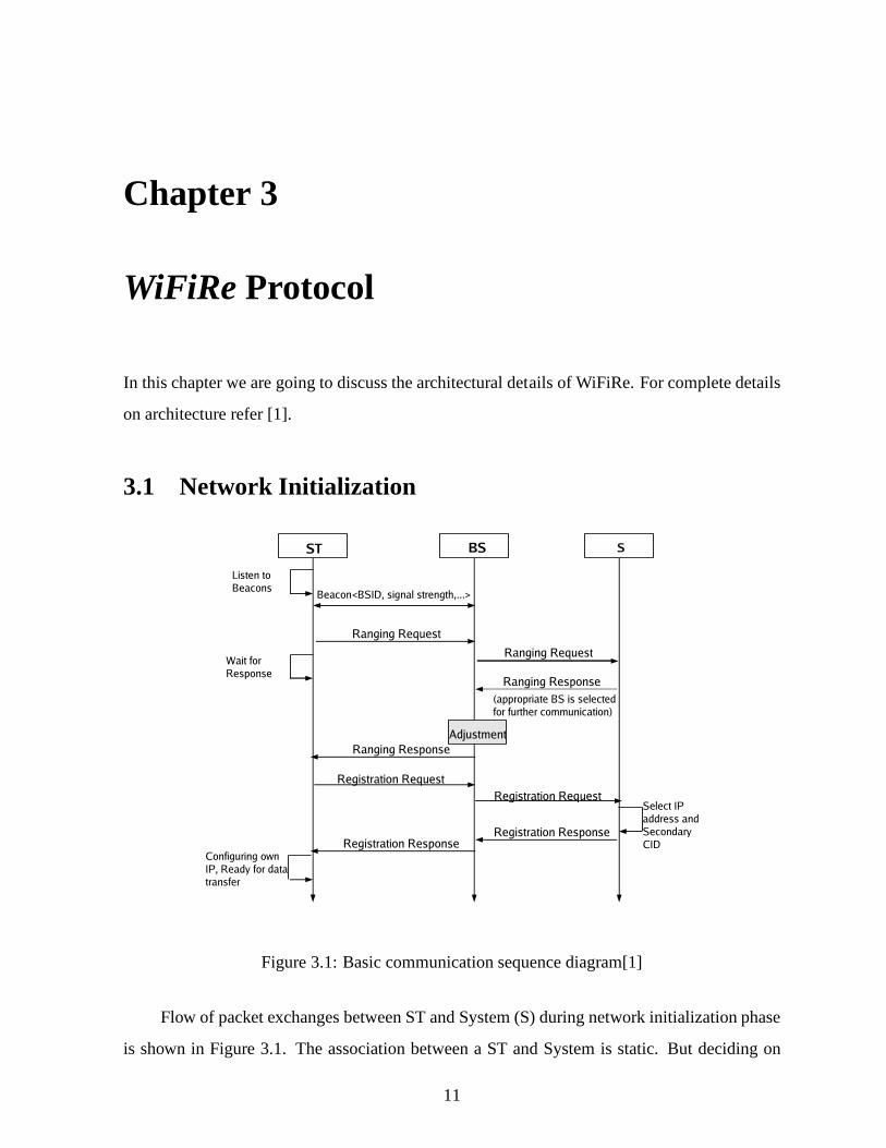
Figure 3.1: Basic communication sequence diagram[1]
Flow of packet exchanges between ST and System (S) during network initialization phase
is shown in Figure 3.1. The association between a ST and System is static. But deciding on
11
which BS to use for communication is done through ranging andregistration process. New
and non-synchronized STs are allowed to range and register.When power-up sequence and
self-initialization are done the ST enters the process of Ranging in order to synchronize the
clock and other physical parameters with the System (S). It is also performed periodically to
keep in synchronization with S. In this process S assigns ST two connection-IDs (CIDs) called
Primary CID (PCID) and Basic CID (BCID). PCID is used furtherfor exchange of management
services and BCID is used further for periodic ranging requests. Registration process required
prior to any data connection. During this process, ST and S exchanges operational parameters
and capabilities. Registration process enables the ST to acquire IP address to setup provisioned
connections.
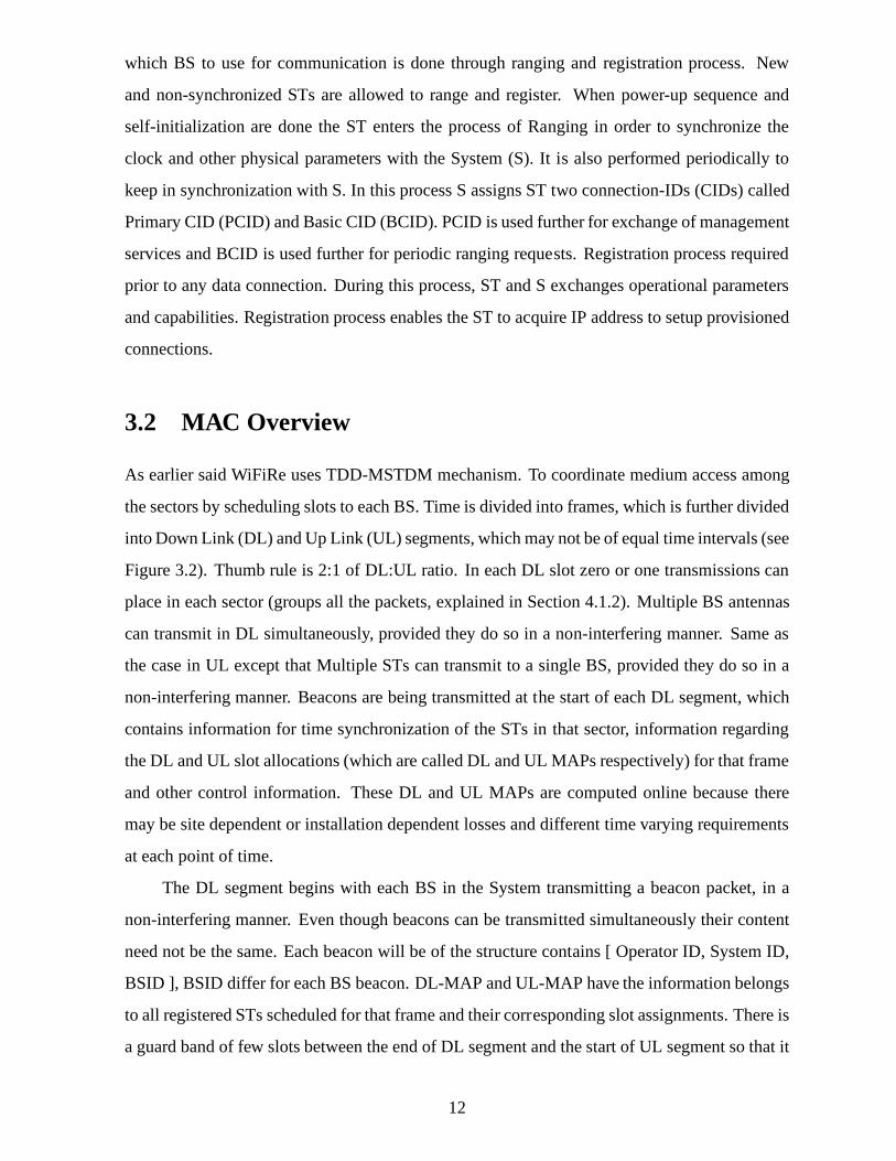
3.2 MAC Overview
As earlier said WiFiRe uses TDD-MSTDM mechanism. To coordinate medium access among
the sectors by scheduling slots to each BS. Time is divided into frames, which is further divided
into Down Link (DL) and Up Link (UL) segments, which may not beof equal time intervals (see
Figure 3.2). Thumb rule is 2:1 of DL:UL ratio. In each DL slot zero or one transmissions can
place in each sector (groups all the packets, explained in Section 4.1.2). Multiple BS antennas
can transmit in DL simultaneously, provided they do so in a non-interfering manner. Same as
the case in UL except that Multiple STs can transmit to a single BS, provided they do so in a
non-interfering manner. Beacons are being transmitted at the start of each DL segment, which
contains information for time synchronization of the STs inthat sector, information regarding
the DL and UL slot allocations (which are called DL and UL MAPsrespectively) for that frame
and other control information. These DL and UL MAPs are computed online because there
may be site dependent or installation dependent losses and different time varying requirements
at each point of time.
The DL segment begins with each BS in the System transmittinga beacon packet, in a
non-interfering manner. Even though beacons can be transmitted simultaneously their content
need not be the same. Each beacon will be of the structure contains [ Operator ID, System ID,
BSID ], BSID differ for each BS beacon. DL-MAP and UL-MAP havethe information belongs
to all registered STs scheduled for that frame and their corresponding slot assignments. There is
a guard band of few slots between the end of DL segment and the start of UL segment so that it
12
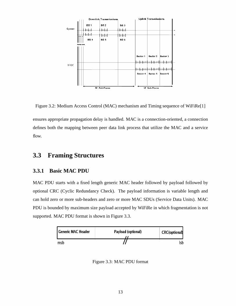
Figure 3.2: Medium Access Control (MAC) mechanism and Timing sequence of WiFiRe[1]
ensures appropriate propagation delay is handled. MAC is a connection-oriented, a connection
defines both the mapping between peer data link process that utilize the MAC and a service
flow.
3.3 Framing Structures
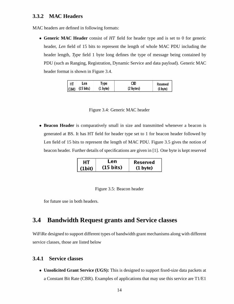
3.3.1 Basic MAC PDU
MAC PDU starts with a fixed length generic MAC header followedby payload followed by
optional CRC (Cyclic Redundancy Check). The payload information is variable length and
can hold zero or more sub-headers and zero or more MAC SDUs (Service Data Units). MAC
PDU is bounded by maximum size payload accepted by WiFiRe in which fragmentation is not
supported. MAC PDU format is shown in Figure 3.3.
Figure 3.3: MAC PDU format
13
3.3.2 MAC Headers
MAC headers are defined in following formats:
• Generic MAC Header consist ofHT field for header type and is set to 0 for generic
header,Len field of 15 bits to represent the length of whole MAC PDU including the
header length,Typefield 1 byte long defines the type of message being contained by
PDU (such as Ranging, Registration, Dynamic Service and data payload). Generic MAC
header format is shown in Figure 3.4.
Figure 3.4: Generic MAC header
• Beacon Headeris comparatively small in size and transmitted whenever a beacon is
generated at BS. It has HT field for header type set to 1 for beacon header followed by
Len field of 15 bits to represent the length of MAC PDU. Figure 3.5 gives the notion of
beacon header. Further details of specifications are given in [1]. One byte is kept reserved
Figure 3.5: Beacon header
for future use in both headers.
3.4 Bandwidth Request grants and Service classes
WiFiRe designed to support different types of bandwidth grant mechanisms along with different
service classes, those are listed below
3.4.1 Service classes
• Unsolicited Grant Service (UGS):This is designed to support fixed-size data packets at
a Constant Bit Rate (CBR). Examples of applications that mayuse this service are T1/E1
14

emulation and VoIP without silence suppression. The mandatory service flow parameters
that define this service aremaximum sustained traffic rate, maximum latency, tolerated
jitter and request/transmission policy.
• Real-time Polling Service (rtPS):This service is designed to support real-time service
flows, such as MPEG video, that generate variable-size data packets on a periodic ba-
sis. The mandatory service flow parameters that define this service areminimum reserved
traffic rate, maximum sustained traffic rate, maximum latency and request/transmission
policy. The BS shall provide periodic unicast request opportunities, by assigning appro-
priate polling slots in the UL.
• Non-real-time Polling Service (nrtPS):This service is designed to support delay-tolerant
data streams, such as an FTP, that require variable-size data grants at a minimum guar-
anteed rate. The mandatory service flow parameters to define this service areminimum re-
served traffic rate, maximum sustained traffic rate, traffic priority, and request/transmission
policy. The BS typically polls nrtPS CIDs on an interval (periodic or non-periodic).
• Best Effort Service (BE): This service is designed to support data streams, such as Web
browsing, that do not require a minimum service-level guarantee. The mandatory service
flow parameters to define this service aremaximum sustained traffic rate, traffic priority,
and request/transmission policy.
3.4.2 Type of Grants
Types of band width grant mechanism which are intend to support in WiFiRe as per draft are
listed below.
• Grant per Connection (GPC): System (S) explicitly grants for each connection.
• Grant per Subscriber Station/Terminal (GPSS): All connections from a single SS are
treated as a single unit and bandwidth is being allocated accordingly. An additional sched-
uler in SS determines in which order the service is being granted slot.
• Grant per Flow Type (GPFT): Grants are allocated based on service flow type.
15

Chapter 4
WiFiRe Design and Implementation
Overview
This chapter explains previous work done in WiFiRe design and implementation [4][5]. It in-
cludes design of WiFiRe, how WiFiRe System (S) connected with different BS antennas and
different assumptions made during the implementation. Andalso explains present implementa-
tion plan.
4.1 Design Overview
4.1.1 Real System Components
In current WiFiRe implementation plan,WiFiRe-MACandBS-PHYare separate from each other
(see Figure 4.1). PHY boards are being developed independently and require MAC frame to
be delivered on Ethernet cable. Eventually, MAC and PHY willbe integrated as single entity.
Current hardware keep six different NICs for six BSs. These six NICs are connected by single
switch.
This leads to Ethernet cable as single communication medium. All the non-WiFiRe control
messages such as 2 byte control data (explained later in thischapter) have to be transferred
using same link. Extra control modules have to be written to handle, because such messages
adds more complexity to implementation. WiFiRe frames are to be sent to this switch with
destination address as a given BS-PHY MAC address. Frame structure and slot size is fixed.
There is a centralized module which instructs all six BS-PHYs to synchronize with each other
16

Figure 4.1: BS hardware: proposed WiFiRe real system component [5]
and send data as and when required.
4.1.2 Proposed solution for reducing PHY overhead
In our approach both BS-PHY and BS-MAC are separate from eachother (Figure 4.1). There
are various ways (broadcast, indexing, bitmap and consecutive allocation) to transmit a frame
which is built by WiFiRe MAC from BS-MAC to respective BS-PHYsuch that each BS-PHY
should know when to transmit the data frame.
We also need to optimize the PHY overhead, which is of 4 slots,for every new trans-
mission at BS-PHY [1]. Among the available methods, concatenation has low PHY overhead.
Using concatenation we allocate all slots which belong to same BS consecutively, thereby re-
ducing PHY overhead. We use a 2 byte control packet per DLTB (Down Link Transport Block),
having information<starting slot, number of consecutive slots> and then transmitted to BS-
PHY. At BS-PHY, it reads the information present in control packet and acts accordingly.
Figure 4.2 shows how this approach works. Total DL frame is divided into groups (B1,
B3, B5 are in a group) and each group belongs to the respectiveBS-PHY. Beacons are trans-
mitted to every BS-PHY at same time. Down link Transport Blocks (DLTB is a group of slots
which belongs to the same BS. Each BS have zero or more DLTBs and this number depends on
Ethernet packet size) are created before inserting the WiFiRe frame into Ethernet packets.
17

Figure 4.2: Consecutive allocation of DL slots for each BS [4]
For example, when BS-PHY receives an Ethernet packet havinga control packet<05,15>,
it transmits from slot 05 to 19. This method has advantage of fixed size memory requirement
(PHY buffer need to store single frame at any given time) at BS-PHY, minimal control and
PHY overhead. However it increases the complexity of scheduler. Scheduler has to take care of
constructing DLTBs.
Information present in the MAPs and CID table is helpful for ST-PHY (antenna) to trans-
mit and receive data. Appropriately above procedure is applied for UL as well for reducing
PHY overhead at ST. In that case, grouping of slots are done atST level instead of BS.
4.1.3 Assumptions made on PHY board
By considering above design details we started working on emulation of protocol using testbed
due to absence of actual hardware. We have discussion with the group who are handling WiFiRe
PHY part, then prepared some assumptions during the implementation. One of the important
agreement between our two groups (IITM and IITB groups) is, we need to send DLTBs along
with small control packet (refer section 4.1.2) to appropriate BS-PHY in case of BS. We believe
that, lot of modules we are implemented be used directly in actual hardware, there will be some
miner changes expected.
The list of assumptions made during the emulation (at PHY) are as follows
18

(a) Clock has capable of generating 1 tic per every time slot.
(b) Board had capable of reading control packet and transmitting DLTBs at appropriate
time slots.
(c) Handling multiple Ethernet Packets at Board. Because some times single DLTB may
not be sufficient for transmitting all the slots which belongs to single BS.
(d) Buffer with min size of a complete frame (210 * 44B) is required. This is equivalent
to 7 Ethernet Packet (1500B). Assuming that only one frame will present at a given frame
interval.
(e) FCFS queue at BS.
4.2 Implementation Overview
4.2.1 LAN emulation
We have emulated the WiFiRe protocol using LAN as the basic medium of propagation between
ST and BS. In emulation, WiFiRe MAC layer is over applicationlayer implemented using C
sockets on Ethernet LAN where it will construct, process andexecute the packets on the WiFiRe
MAC and will pass the packet to socket layer assuming it to be the PHY layer of WiFi 802.11.
The assumption here is that the application layer of the Ethernet act as the MAC layer of our
protocol and assuming the layers down to it as the PHY. Here the characteristics of PHY layer
can be ignored while implementing the MAC layer through C sockets as the device driver will
take care of the PHY at lower levels.
Why Emulation on LAN?[4]
1. To understand and ensure that steps involved in WiFiRe protocol works.
2. It is comparatively easy to debug and make changes at the application layer rather than at
kernel level.
3. WiFiRe hardware is not ready and in order to test the protocol, there is need of already
setup network infrastructure which is already setup(i.e. LAN in this case).
19

4. Design and implement data structures and small working modules in order to test and
reuse them with minimum changes when porting them on actual hardware
4.2.2 Testbed setup
Figure 4.3: WiFiRe Test Bed
WiFiRe testbed shown in Figure 4.3 includes a BS with two NICs, an ST with two NICs,
a server(or gateway) which acts as FTP, Proxy and web server.Proxy server takes care of
forwarding all HTTP/FTP requests to Internet. Several end-users (Clients) are connected to ST
through Ethernet switch. BS is connected to ST using DIX based Ethernet cross cable. This
link is treated as wireless link of WiFiRe. Subsequently, itwill be replaced with the hardware
for WiFiRe PHY. STseth0 is connected with end users via switch. BS is connected to server
usingeth0and sends data to ST by other interfaceeth1. eth0of ST and BS have plain 802.3
MAC based connectivity and it makes the network transparentfor end users and S respectively.
End-user clients send packets to ST, ST follows WiFiRe MAC slot structure (refer section 3.2)
and sends packets to BS in designated slots. BS receives these packets, processes using WiFiRe
modules and forwards them to S as normal Ethernet packets. Server sends reply to BS, which
forwards to appropriate ST and finally, Client receive the packets. More than one server can
be connect to the system S via switch. In our case, a proxy server which is running a squid
proxy[10] helps to connect Internet and a VoIP gateway[13] helps to connect PSTN network.
Configuration details about Proxy settings and VoIP gatewayare included in Appendix A.
20

Assumptions and limitations of WiFiRe Emulation
• Both BS and ST are connected using a cross cable, which eliminates problems of propaga-
tion delays, ranging, synchronization and other such wireless specific issues. We assume
that such issues will be taken care by underlying hardware inactual implementation.
• Implementation does not perform real ranging procedure as test-bed uses Ethernet cable
where propagation delay is not variable. In this scenario, Beacon transmission is enough
for synchronization. Purpose of ranging here is to assign and transfer basic and primary
CIDs only.
• As our emulation runs on Ethernet, and PCs are connected directly using RJ-45 cables, it
can not get total flexibility on frame structure, size, CRC etc. This Ethernet link restricts
size of individual packets and WiFiRe MPDUs as well.
• Due to absence of real hardware clock, software timers are used in implementation which
guarantees precision up to milliseconds.
4.2.3 GPSS mode
Among the available grant services (ref section 3.4.2) we selected GPSS mode for implemen-
tation due to simplicity. In GPSS mode, all connections froma single ST are treated as a single
unit and BW is being allocated accordingly. Mode of BW allocation is completely depends on
scheduler and Call Admission Control (CAC) at BS. An additional scheduler at ST determines
whom to allocate available slots. Same scheduler can also beused at ST.
In GPSS mode, total functionalities distributed between BSand ST. In this mode, decision
about DL slots will be taken at BS, but decision about UL slotswill be taken at ST. Available
UL slots are distributed among active STs at the time of framesent. Each ST has its own local
scheduler, it allocate allotted slots between clients.
There are some other reasons for selection are listed below,
• We want to make design as simple as possible (we want to avoid the problems created by
the data connections or dynamic change of connection requirements at this level).
• Helps to effective utilization of available BW (probability of availability of data packets
which belongs to particular connection at a given time is much lower than whole ST
aggregated connections).
21

• We can easily extend to GPC mode by making related changes at BS.
• It also avoids the work load done by the System S.
4.3 Modules at BS and ST
Figure 4.4: Block diagram for BS
As shown in Figure 4.4, BS MAC functionalities distributed between different modules.
Modules namely packet classifier, CID generator, packet controller, scheduler and MAP gener-
ator,Memory Management Unit (MMU) and timer clock. Also includes some of the supporting
modules like filters, emulation stats, debug logs and configuration to help further debugging
purpose and also useful for end user. Each module has specifictask in the protocol implemen-
tation. Overview of the modules are given below. Complete details like how each module work
and significance of particular module is described in next chapter.
22
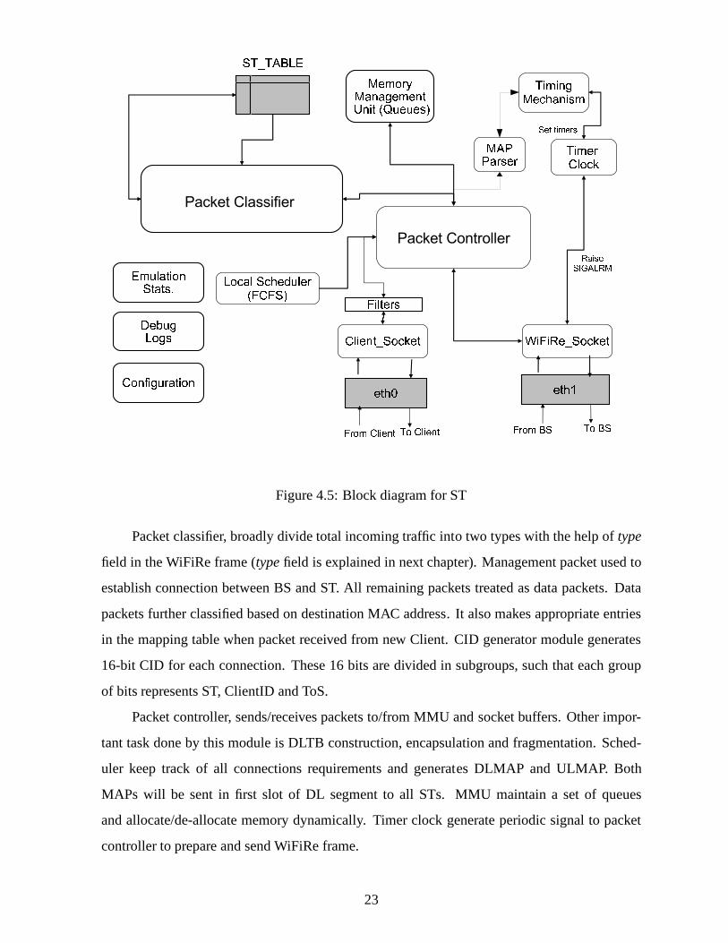
Figure 4.5: Block diagram for ST
Packet classifier, broadly divide total incoming traffic into two types with the help oftype
field in the WiFiRe frame (typefield is explained in next chapter). Management packet used to
establish connection between BS and ST. All remaining packets treated as data packets. Data
packets further classified based on destination MAC address. It also makes appropriate entries
in the mapping table when packet received from new Client. CID generator module generates
16-bit CID for each connection. These 16 bits are divided in subgroups, such that each group
of bits represents ST, ClientID and ToS.
Packet controller, sends/receives packets to/from MMU andsocket buffers. Other impor-
tant task done by this module is DLTB construction, encapsulation and fragmentation. Sched-
uler keep track of all connections requirements and generates DLMAP and ULMAP. Both
MAPs will be sent in first slot of DL segment to all STs. MMU maintain a set of queues
and allocate/de-allocate memory dynamically. Timer clockgenerate periodic signal to packet
controller to prepare and send WiFiRe frame.
23
Filter module drops packets based on predefined rules (rulesare explained in section 5.7).
Stats modules helps in calculating different statistics like number of frames sent, emulation
duration, number of data packets Tx/Rx etc. Debug and Logs module keep track of flow of
protocol and log all the details into a file. Configuration module read all config parameters from
config file, if any value missing from config file then it assign default values. All details about
configuration parameters and default values are explained in Section 5.7.
As shown in Figure 4.5, ST also have similar but simpler MAC compare to BS. ST has
MAP parser instead of MAP generator helps to send signals to packet controller for Tx/Rx
packets at particular time based on present MAP. When packetclassifier received a packet from
a new client, it make entries in ST-TABLE. Local scheduler schedules UL traffic. Timer clock
generate SIGALRM signal to packet controller to Tx when UL frame started.
24
Chapter 5
WiFiRe Implementation Modules
This chapter explains detailed functionalities of WiFiRe module. Here, every section is ex-
plained with respect to actual implementation.
5.1 Threads, Buffers, Sockets and their interaction
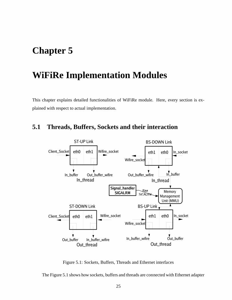
Figure 5.1: Sockets, Buffers, Threads and Ethernet interfaces
The Figure 5.1 shows how sockets, buffers and threads are connected with Ethernet adapter
25

at ST and BS in actual implementation.In this figure alleth1are in same subnet (ex:192.168.1.*
/255.255.255.0). Alleth0, Proxy and all Clients should be under same subnet (ex:172.168.1.*
/255.255.0.0) for communication.
Various modules in BS and ST, dedicated to different functions of WiFiRe MAC are shown
in Figure 4.4 and Figure 4.5. There are completely four threads running at both BS and ST.
Responsibilities of each thread at higher level are as follows:
• main thread: Initializing tables, buffers, queues, setting config values, activate timer
clock, creating sockets, reading local MAC details and keeping track of console to display
stats
• signal handler: when ever it catches a SIGALRM signal it will do following twoactions
in sequence,
1. Dequeue raw Ethernet packets fromMMU, create WiFiRe frame (encapsulation of
Ethernet frames) and put it intoOut buffer wifire for DL Tx
2. Read WiFiRe frame fromIn buffer wifire which is Rx in UL, convert them into
normal packets and put them intoOut buffer for Tx
• In thread: At BS, Rx Ethernet frames fromIn socketi.e Ethernet interfaceeth0(from
Proxy) and stores intoIn buffer. At ST, Rx Ethernet frames fromSocketfd i.e Ethernet
interfaceeth0(from Client) and enqueue intoIn buffer. MMU read fromIn buffer and
enqueues into respective queue. In BS, each active ST has onededicated queue to store
frames belonging to that ST for Tx in DL.
• Out thread: At BS, Rx WiFiRe frames fromWifire socketi.e Ethernet interfaceeth1
(from WiFiRe network during UL), and put them intoIn buffer wifire. At ST, Rx WiFiRe
frames fromWifire socketi.e Ethernet interfaceeth1(from WiFiRe network during DL)
and put them intoIn buffer wifire. MMU readsIn buffer wifire and either deques from
respective queue or put it intoOut buffer for Tx through socket.
In addition to above, MMU has one additional queue for holding broadcast packet (DCID =
0xfff). Our simple scheduler (FCFS) reads frames from queues one by one till the queue empty.
26

5.2 Timer Management
Timer management modulereads theFRAME DURATION value fromconfiguration module
and set the SIGALRM period by callingwifire setalarm(). settimer()is an API declared in
#include<systime.h>. The code snippet ofwifire setalarm()is given below,
unsigned int wifire setalarm(unsigned int sec, unsigned long
int intv) {
//sec = start after, intv = FRAME DURATION, usec means in micro seconds
struct itimerval new, old;
//interval is for frame periodicity
//dont make interval=0; it will be set only once
new.it interval.tv sec = 0;
new.it interval.tv usec = (long int)intv;
//dont make it value=0; it will disable alarm
//it value defines when to start first interrrupt after process starts
new.it value.tv sec=0;
new.it value.tv usec = 1;
if(setitimer(ITIMER REAL ,&new, &old)<0)
return 0;
else return old.it interval.tv sec;
}
By setting this value, system clock generates sequence of SIGALRM signals with speci-
fied interval.signal handler()catches this signal and prepares for frame Tx in DL. This module
is implemented only at BS. ST starts Tx in UP link after immediate completion of DL Rx. We
havn’t implemented timer at slot level due to soft timer limitations. We did not consider any
propagation delay between ST and BS, because our testbed machines are connected through
Ethernet cables.
5.3 CID generator
The format of the CID is shown in Figure 5.2. The first two bits implicitly identify the type of
the CID: (00) implies it is a basic CID; (01) implies primary CID; both (10) and (11) imply data
27

Figure 5.2: CID format
CID. In case of data CID,the next two bits implicitly identify the type of the associated service
flow: (00) for UGS, (01) for rtPS, (10) for nrtPS and (11) for BE.
CID generatorreturn new CID based on request type and service flow at BS. In current
implementation BCID and PCID are issued at in response to receivedranging requestand also
make proper entries in BS-TABLE. DCID is issued when ever BS receives first data packet
from new Client and also makes entry in the ST-MAPPER table. In case, particular CID count
reaches maximum number then this module return an error indicating no CID left of this type
and wait till some one removes their CID from the active list.There are some special CIDs
0x0000, 0xffff etc.implemented based on draft[1], those are used for some special purpose. For
example,0xffff used for broadcast packets and all STs read this frame in DL,0x0000used to
transmit dummy frames if required. Present implementationsupport only BE traffic, all the
incoming traffic is treated as BE.
5.4 Packet Controller
Packet controller is responsible for storing all incoming packets from proxy to respective ST
queue with the help of memory management unit. It is also responsible for constructing WiFiRe
data frame by embedding Ethernet packets, and also do reverse operation at other end. When
ever it receive SIGALRM signal it starts constructing WiFiRe DL frame with help of DLTB con-
struction module and fragmentation module by using currentDL-MAP generated by Scheduler
and MAP generator. MAP generator also prepares UL-MAP. All available slots in UL-MAP is
equally distributed among all active STs. After creation ofcurrent frame it Tx beacon frame
followed by data frame. Packet controller at BS in UL, forwards all incoming data packets to
packet classifier.
Packet Controller at ST forwards the received beacon frame always to the Timing Mech-
anism at ST which generates sequence of time intervals from DL/UL MAP constructed by
scheduler. These sequence is sent to Clock timer to raise SIGALRM at the beginning of des-
28
ignated slot interval. This helps ST to wake-up or become ready to Tx UL frame at designated
time. Here, due to absence of real hardware clock, software timers are used in implementation
which guarantees precision till milliseconds. It also stores all incoming Ethernet packets into
queues with the help of memory management unit.
5.4.1 DLTB construction
Detailed description of DLTB has been explained in section 4.1.2. We have implemented this
module as specified in section 4.1.2, but not at slot level. One of the main aim of implementing
encapsulation and fragmentation modules are to build DLTBs. At present maximum WiFiRe
frame length is equal to one Ethernet frame (1500B), becauseour testbed assumes LAN as
medium of communication.
In DL at BS, Each ST has one specific queue in MMU. Based on scheduler (FCFS in
our implementation) packet controller dequeues packets from each ST queue, till either queue
is empty or max allowed bytes of frame is reached to form DLTB.MAP generator use this
information to build DL-MAP. It also does fragmentation when complete packet will not fit into
the current frame. Fragmented frame is stored in temporaryfragmentbufferalong with STID.
Remaining part of fragmented packet is Tx in next immediate frame. Similar task has been
done at ST in UL, except here MMU has single queue to en-queue all client data packets.
5.5 Packet classifier
All packets received from packet controller are classified into two types (see Figure 5.3)based
on connection identifier type (refer section 5.2).
5.5.1 Management packet handler
As mentioned in section 3.1 there are three basic stepsBeaconing, Ranging and Registration
which constitute network initialization. For each step there is a module in the actual implemen-
tation.
29

Figure 5.3: Packet flow in Packet classifier module
Figure 5.4: Beacon Message
Beacon transmission
BS transmits beacons periodically after System (S) get booted. The period length depends on
the frame size. Packet controller creates beacon frames when it receives SIGALRM signal.
These beacon have the information like SystemID, OperatorID, BSID, DLMAP and ULMAP
as shown in the Figure 5.4. SystemID and OperatorID help to recognize particular network.
These values are given by the service provider and used for authentication purpose.
When ST boots up, it listens the medium for beacon. This process also called PHY syn-
chronization. When first time ST reads beacon packet, it stores all system parameters into local
variables. Now ST is ready to for ranging. ST checks these values on reception of every beacon
to ensure every thing is working correctly.
30

Ranging and Registration
As explained in the previous chapter, during this ranging and registration phase different mes-
sages are exchanged between ST and BS. These messages are Ranging-Request (RNG-REQ),
Ranging-Response (RNG-RSP), Registration-Request (REG-REQ) and Registration-Response
(REG-RSP).
The implementation does not perform real ranging procedureas the testbed uses Ethernet
cable, where propagation delay is not variable. Here, ranging is done to assign and transfer
Basic and Primary CIDs. After ranging procedure ST finally get registered. In Figure 5.5
Figure 5.5: Sequence of steps at ST when it receives responses from BS
explains sequence of steps done by the ST after synchronization. When ST receives RNG-RSP,
it gets allocated Base StationID (BSID), PrimaryCID (PCID)and BasicCID (BCID). In this
example BSID=1, BCID=0001 and PCID=4001. When ST receives REG-RSP, it get DataCID
(DCID). Now ST can transfer data to BS using allocated CIDs.
In Figure 5.6 explains sequence of steps done by BS when it receives a request form
new ST. When ever it receives RNG-REQ, BS make entries in BS-TABLE then allocate PCID,
BCID and BSID. Some times BS receives RNG-REQ from previously allocated ST, this time
BS check for duplicate update. If it found duplicate it send same allocated PCID, BCID, BSID.
These PCID and BCID are used for exchanging management packets. When BS receives REG-
REQ it sends DCID from the available pool. This DCID is used for further data communication.
ST is now ready to serve its Clients request.
31

Figure 5.6: Sequence of steps at BS when it receives new request from ST
Some of the boundary conditions that we are handling are listed below
1. ST rebooted after registration: Start from synchronization.
2. BS rebooted after ST registration: If ST did not receive a beacon in a specified time
interval then it resets all its local values (OperationID, SystemID etc) then get rebooted.
This feature is not handled yet.
3. ST received different operationID: Drop the received packet then start from Ranging.
4. ST received different systemID: Drop the received packet, and restart ranging process
again.
5. ST received packet with different BSID: Drop the packet or ignore it.
6. ST received packets with different STID (ST-MAC): Drop the packet or ignore it.
7. ST never forwards packet till registration done
5.5.2 Data packet handler
After registration is done, clients are allowed to access services like web, ftp, telnet, VoIP etc.
provided by the server. In our implementation DCID is same asclientID. Packets with DCID
type (see Figure 5.2) are treated as data packets and these packets are en-queued into specific
32

ST queue through MMU. These packets are handled differentlyat BS and ST. At ST in DL, all
received data packets from WiFiRe frame are directly forwarded to clients. At BS in UL, all
received data packets further categorized based on destination MAC.
1. Proxy packets: Packet with destination MAC as proxy will be forwarded to proxy di-
rectly.
2. Local Traffic : Packet with destination MAC as any one of its local client, then packet is
enqueued to respective ST queue.
3. Broadcast packets: Packets with destination address with all 0xff are sent to proxy and
also enqueued to broadcast queue. These packets are transmitted in DL with special CID
(0xffff). ST Rx all packets in DL (because DL is broadcast) but reads packets matching
with its own DCID and also DCID with0xffff, all other packets are dropped.
Local Traffic Diversion (LTD)
This module is implemented only at BS, and helps to provide communication with in the
WiFiRe network (between different STs). When ever packet classifier receives data packet
and finds (with help of ST-TABLE) that the received packet is intended for local WiFiRe Client,
then it enqueues the packet to destination Client ST queue for DL transmission. Otherwise
packet is transmit to Proxy directly.
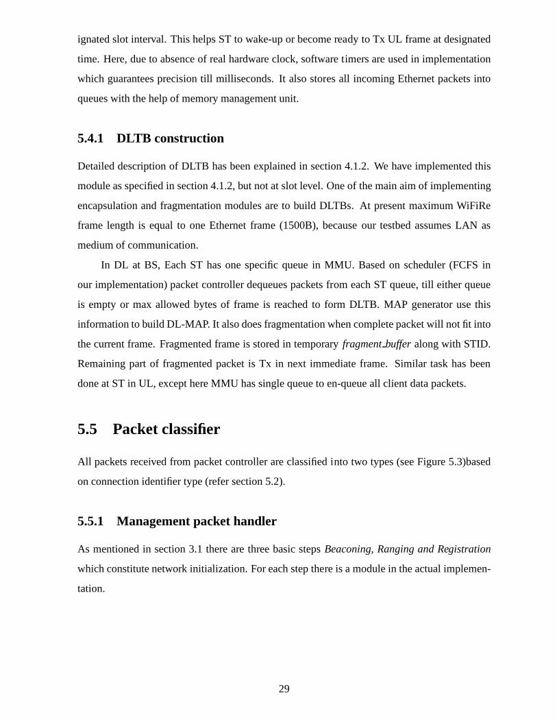
5.6 Tables
Table 5.1, explain ST-TABLE entries, size of each entry and short description about it. This
table is stored at ST and updated when ever new client packet arrives. Table 5.2, describe
fields in ST-MAPPER, and this table make entries when it receive ranging and registration
request from new ST. Table 5.3, describe different fields in BS-TABLE, and this table make
entries when it receive a new connection request from some active ST Client. All supplementary
functions to access Tables are implemented.
33
Field Type Size in Bytes Remarks
DCID 2 Data Connection Identifier; connectionID, primary key
Type 1 Flow type (UGS = 0, rtPS = 1, nrtPS = 2 and BE = 3). Not used
ClientID 6 Client Identifier; Client MAC
Validity 1 indicates connection status
Table 5.1: ST-TABLE at ST; used for storing Client details atST
Field Type Size in Bytes Remarks
STID 6 Subscriber Terminal Identifier; ST MAC address, primary key
BSID 1 Base Station Identifier [1..6]
BCID 2 Basic Connection Identifier; used for periodic Ranging
PCID 2 Primary Connection Identifier; used for management packets
Table 5.2: ST-MAPPER at BS; used for mapping between ST and BS
Field Type Size in Bytes Remarks
ClientIP 4 (6) IP address of Client. Not used
DCID 2 Data Connection Identifier; connectionID, primary key
Type 1 Flow type (UGS = 0, rtPS = 1, nrtPS = 2 and BE = 3). Not used
STID 6 Subscriber terminal Identifier; ST MAC address
ClientID 6 Client Identifier; Client MAC
upfragment - To hold fragmented pkt in Up-Link if fragment exists of this ST
Downfragment - To hold fragmented pkt in Down-Link if fragment exists of this
ST
Brokenflag - Indicates fragment status; 1 = fragment exist, 0 = no fragment
LTDQHead - Local Traffic Diversion queue head; holds pkts for with in system
total packets 2 Current buffer size of this ST (in terms of packets)
statspacketstx 2 Total number of packets transmitted from this ST; used for stats
and debug
Table 5.3: BS-TABLE at BS; used for storing Client details atBS
34

5.7 Filters and Stats display
Filters
During the implementation and experimenting process, we observed lot of illegal packets af-
fecting the performance of WiFiRe. This module is implemented at both ST and BS. Examples
of illegal packets are,
• Packet with destination MAC as{0x00, 0x00, 0x00, 0x00, 0x00, 0x00}
• Packet with destination MAC as its own BS MAC, i.e destined for eth1(proxy interface)
received from Proxy in BS
• Packet with destination MAC as its own ST MAC, i.e destined for Client interface (eth1)
received from Client in ST
• Packet with destination MAC with other than local WiFiRe clients
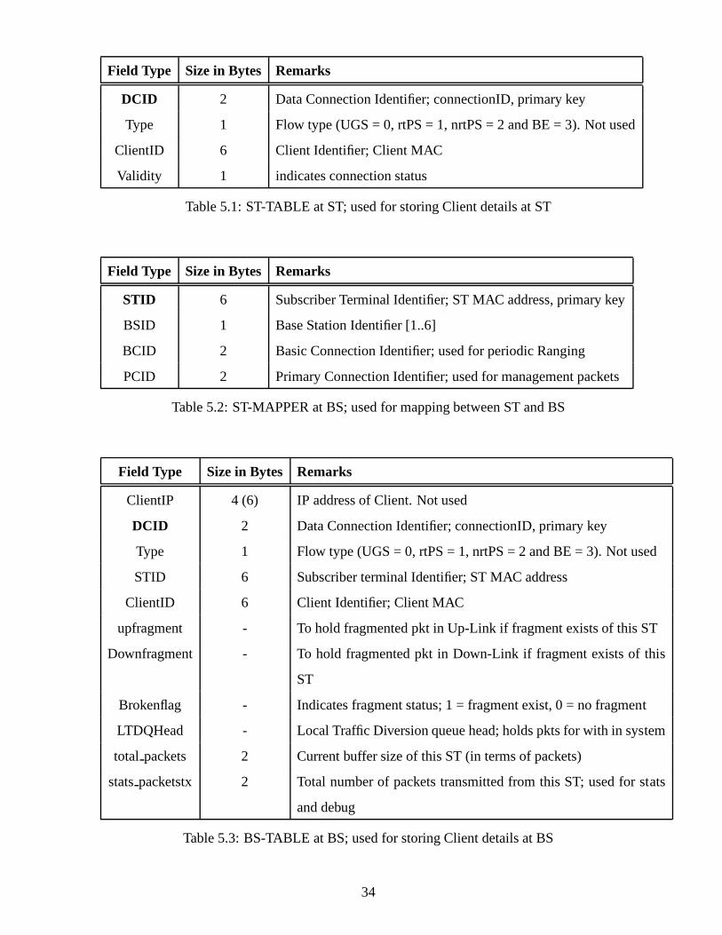
Stats display
We implemented few features in GUI for supporting end user. This is also helpful in measuring
performance of WiFiRe. All the functions relating to emulation statistics are implemented
under this module. Statistics include emulation duration,number of frames sent, number of
data packets Tx/Rx, packet drop count, display of present UL-MAP and DL-MAP, list of active
STs (BS-TABLE), list of active Clients (ST-MAPPER), etc.
Figure 5.7 shows one of the output screenshot, where programran more than 7hr (26867
sec, in this case) with only ping active between Proxy and Client. The active ST and Client
MAC can observe in the same figure. Total number of frames Tx isaround 2686648 (with
frame length = 10ms) which also prove the working of soft timer. Packet drop count (2246)
indicates, these many number of packets were dropped because of any one condition getting
satisfied from filters section.
We also support certain commands like h-help, s-show stats,a-advanced stats, x-exit from
running, m-display current MAP and r-to restart emulation.It also displays all configuration
variable values before beginning of emulation.
35
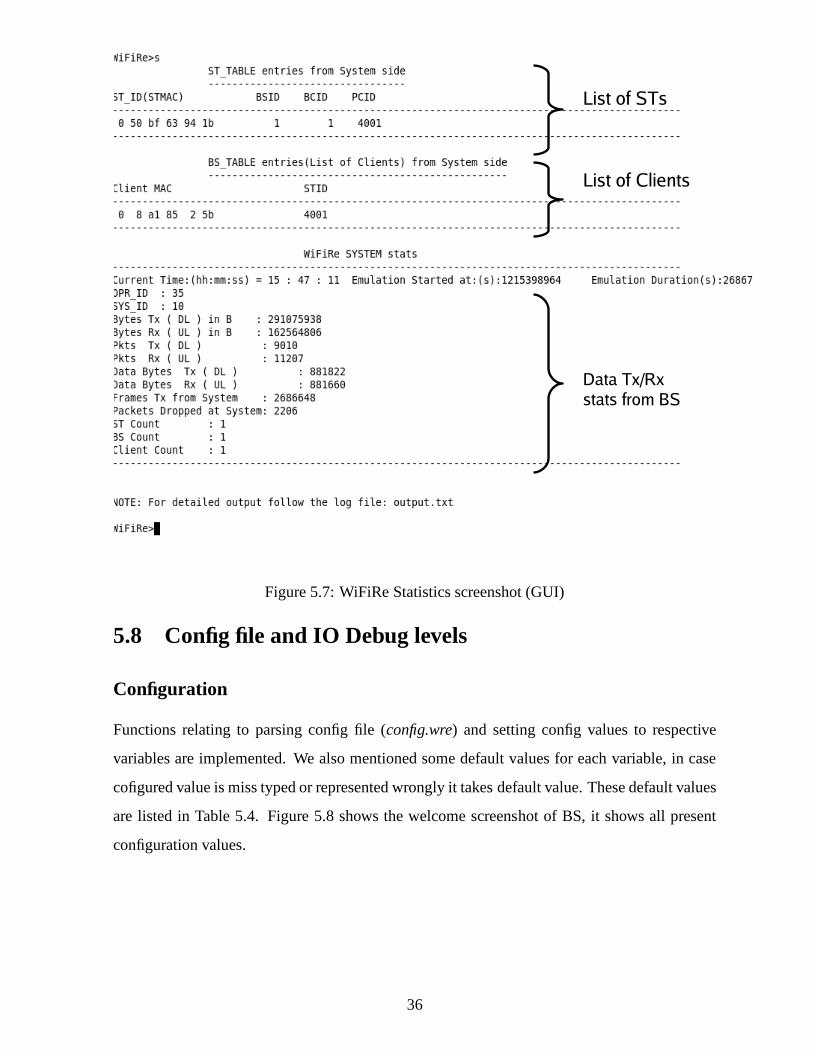
Figure 5.7: WiFiRe Statistics screenshot (GUI)
5.8 Config file and IO Debug levels
Configuration
Functions relating to parsing config file (config.wre) and setting config values to respective
variables are implemented. We also mentioned some default values for each variable, in case
cofigured value is miss typed or represented wrongly it takesdefault value. These default values
are listed in Table 5.4. Figure 5.8 shows the welcome screenshot of BS, it shows all present
configuration values.
36

Config variable BS,ST Default value Remarks
opr id BS 10 OPRID
sys id BS 35 SYS ID
frame lengthmilli BS 10 frame length in milli seconds
mtu threshold BS, ST 1400 MTU max threshold
max buffer length BS, ST 100 Max buffer length per ST in packets
max st idle time in sec ST 5 max ST scan or idle time, if BS goes
down or ST just wake-up on sec
bs tableflush time in sec BS 120 for removing in-active clients from sys-
tem
st2bsinterface ST eth0 ether card name between st and bs
st2clientinterface ST eth1 ether card name between st and client
bs2stinterface BS eth0 ether card name between bs and st
bs2proxyinterface BS eth1 ether card name between bs and proxy
proxy mac BS MAC[6] proxy mac, should be in config file, BS
can’t read itself
voip gatewaymac BS MAC[6] VOIP GW mac, if present
max st scantime in sec ST 5 max ST scan time, if BS goes down or ST
just wake-up on sec
debuglevel ST, BS 5 sets the debug level depth, for complete
list refer Table 5.8
Table 5.4:Config.wre:Different configuration variables and their default values
37

Figure 5.8: List of red Config values and Menu commands
IO Debug levels
In order to keep track on the execution of the protocols, DEBUG LEVELS has been introduced
to get output information at user defined level of depth. Table 5.5 defines the levels and their
purpose of execution.
Memory management unit (MMU), encapsulation, fragmentation modules are explained
in [2]. All the modules we implemented are functioning properly as we expected without any
interruption for longer time.
38

Debug Level Purpose
0 No Output
1 Event And High-Level Information Messages
2 Track The Flow Of Command Processing
3 For Inner Loops, Table Traversals, Etc
4 I/O Debug - Mover Messages Traces
5 Trace-Level Debug
6 Redundant Information
Table 5.5: Debug Levels
39

Chapter 6
Experiments and Learnings
This chapter describes the experiment conducted during theimplementation. And slo listed
technical problems we encountered during the implementation of protocol. The observations,
guesses, causes and the solution to problems are also described.
6.1 Experiments conducted
As mentioned earlier, our primary goal is to provide web and VoIP connectivity between WiFiRe
client and outside client. We spent lot of time for setting uptestbed and tested with different
kinds of traffic loads. For experimental purpose we conducted these tests in our lab.
6.1.1 Within same ST
List of experiments we have conducted are given below,
• Ping interaction between Client and Proxy :Able to ping betweenClient11andProxy
as shown in Figure 6.1, and also achieved round trip delay of less than 20 ms. Theoretical
value should be more thanFRAME DURATION, i.e 10ms in our case.
• VoIP call between local WiFiRe Client to PSTN phone via Gateway : Able to make
call fromClient11to land-line phonelocated outside in PSTN. Also achieved un-interrupted
quality of voice.
• Accessing Internet pages :Able to make TCP connection with outside server with-
out any connection break in between. Example, fromClient11 we are able to access
www.google.compages.
40
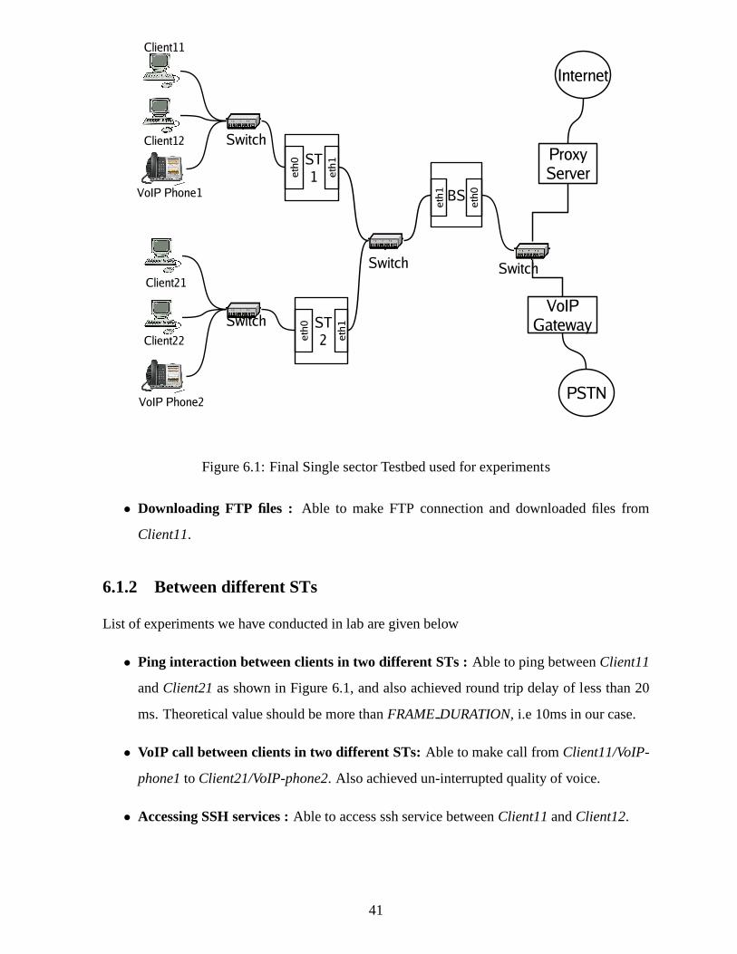
Figure 6.1: Final Single sector Testbed used for experiments
• Downloading FTP files : Able to make FTP connection and downloaded files from
Client11.
6.1.2 Between different STs
List of experiments we have conducted in lab are given below
• Ping interaction between clients in two different STs :Able to ping betweenClient11
andClient21as shown in Figure 6.1, and also achieved round trip delay of less than 20
ms. Theoretical value should be more thanFRAMEDURATION, i.e 10ms in our case.
• VoIP call between clients in two different STs:Able to make call fromClient11/VoIP-
phone1to Client21/VoIP-phone2. Also achieved un-interrupted quality of voice.
• Accessing SSH services :Able to access ssh service betweenClient11andClient12.
41
Other Applications required to conduct experiments
For all above experiments, we consider frame duration as 10ms, and proxy as a gateway. For
supporting different types of traffic like web, ftp, VoIP etc., we need to run certain applications
at ProxyClient.
List of applications required are given below.
• HTTP Proxy: at Proxy, to access Internet, ex: squid proxy [10]
• HTTP Server: at Proxy, to access http pages from proxy, ex: Apache [7]
• VoIP PBX Server: at Proxy, to support VoIP calls, ex: Asterisk [8]
• DHCP Server: at Proxy, to configure IP address dynamically [3]
• DNS Server: at Proxy, to resolve DNS queries coming from client. ex: MaraDNS [9]
• VoIP Client: at Client, to make connection with server, ex: SJPhone [11]
• DHCP Client: at Client, to make DHCP request [3]
• VoIP-PSTN gateway: a device connected in place of proxy, to act as VoIP adapter between
VoIP clients and PSTN network, ex: SPA300 [13]
6.2 Learnings
6.2.1 ARP Cache Flush
• Naive Assumption:Since, the protocol is working correctly for single ST, it should work
for multiple STs under same BS.
• Observation: Although, Proxy is able to reply all ARP requests, it seem that packets are
not reaching ST.
• The Guess: The problem might possibly either ST is not able to receive packets in
WiFiRe network, or it dropped all the packets because they found to be garbled or il-
legal packet.
42

• The Cause: In our implementation forward all broadcast packets to all STs within the
WiFiRe network. ARP request is an broadcast packet, so this packet is transmitted back
to all STs which results same source packet is received at client. It results ARP cache
flushing at client. After some waiting time, now client againsends new ARP request, this
process continued. This results ARP flooding in the network.
• The solution:There are two solutions, we can drop these packets at ST or we can transmit
packets to all active STs other than the originated ST. Second approach, results wastage
of bandwidth because we have to Tx same packet to all other STsindividually (with dif-
ferent DCID’s). We implemented first approach because it avoids duplicate Tx in WiFiRe
network. Broadcast packets are Tx with special DCID (0xeeee). When ever ST receives
this special DCID packets, it search for source MAC in list oflocal Client MAC from
ST TABLE. If entry found then it drops the packet, otherwise Tx to all clients.
6.2.2 Moving from 32 bit to 64 bit machine
• Naive Assumption: Since, the protocol successfully running on IITB testbed, it should
also work at any other testbed.
• Observation: After successful completion of protocol implementation supports single
sector communication, we went to IITM to handover the code for integrating into PHY
hardware. We has done all the testbed setup and configured Clients, STs, BS and Proxy
as we have done at IITB lab. We observed only beacon Tx in DL, weare not able to
exchange single data frame in WiFiRe network.
• The Guess:The problem might possibly that all packets are dropped at both BS and ST,
or our source code has some dependency with machine(PCs) hardware.
• The Cause:After spending some valuable time on debugging, we found at some point we
are capturing address of a memory location into someunsigned intvariable which is of
size 32-bit by default in gcc. We realize that, our lab machines has 32-bit physical address
so our program runns successfully, but new machines need 64-bit field to capture whole
address.
• The solution: We ran a small C program in the testbed machine, and found sizeof
address of memory location as 64-bit. We immediately updated all requiredunsigned int
43

declarations intounsigned long int.
6.2.3 Problem with RTP packets
• Naive Assumption: Since, we are able to establish VoIP call between clients with in the
same ST, it should support for communication among different STs too.
• Observation: All the clients from different STs are able to register with VoIP PBX (ex:
Asterix) by exchanging SIP packets. When ever we made call between two clients, call
gets registered with server successfully. RTP communication works perfectly when two
clients are connected under same ST, but not working for clients under different ST.
• The Guess:The problem might be at BS, either RTP packets are dropping orforwarding
through wrong interface.
• The Cause:BS not forwarding RTP packets back to intended ST.
• The solution: We implemented a moduleLocal Traffic Diversion (LTD). It detects data
packets intended for local clients from UL traffic and put them into respective queue for
DL Tx. LTD is explained clearly in section5.5.2
6.2.4 Problem with Non-WiFiRe packets in WiFiRe network
• Naive Assumption:Since, only our protocol is running in WiFiRe network, only WiFiRe
packets are exchanged between BS and ST.
• Observation: We implemented protocol using PFPACKET socket. PFPACKET socket
family allows an application to send and receive packets dealing directly with the network
card driver. That is, any packet sent through the socket willbe directly passed to the
Ethernet interface [14]. But some how we are receiving general Ethernet frames (ex: ARP,
multicast etc. any packet generated by ST or BS machine) withsource address of either
BS or ST interface. It results in program termination with error messageSegmentation
fault.
• The Guess:These non-WiFiRe packets are treated as WiFiRe packets, results wrong off-
set calculation in packet extraction. This might be force process to access illegal memory
location.
44
• The Cause: Either BS or ST machines itself trying to communicate with others. Lets
consider a situation, where BS want to communicate (ping, web traffic etc) with ST, then
BS generates one ARP query into WiFiRe network. Now ST receives this packet (because
both are connected to same switch) and assumes it as WiFiRe packet, and trying to read
data bytes with help of available MAP, resultssegmentation fault.
• The solution: We implemented aFilter module to filter out non-WiFiRe packets. All
such packets are dropped.
6.2.5 Problem with multiple DHCP servers
• Observation:Since, our protocol works perfectly with L2 switch, we started testing the
protocol by replacing L2 switch Access Point (AP). We generated DHCP request from
client and got reply. We observed no packet transmissions between client and ST, instead
we received packets with different IP.
• The Guess:Something going wrong at AP, because observed packets at ST belongs to
AP subnet.
• The Cause:By default AP activated its own DHCP server
• The solution: Either replacing the AP with Switch or disabling DHCP service we can
solve this problem.
6.2.6 Memory Management Unit
• Naive Assumption: Since, we implemented semaphore to access different memorylo-
cations and buffer queues, it should not give any memory related errors during protocol
execution.
• Observation: Although, protocol runns perfectly in our testbed, at some random point of
time execution is halted with error message indicating eitherSegmentation faultor double
free or corruption.
• The Guess:Machine generates high priority interrupt (segmentation fault) when you have
done some illegal operations on memory.
45

• The Cause:There are two threadsin threadandout threadin our implementation at both
ST and BS. We are dynamically allocating and freeing memory for data packets. Some
how one of the thread was trying to access/free the memory location which is already
freed. Because of high priority interrupt, we are not able tofind exact location in source
code where things went wrong by reading debug messages
• The solution:We solved this problem by implementing an efficient memory manage-
ment unit (MMU) at both ST and BS. It has two modulesmy malloc() andmy free().
my malloc()method allocate requested memory and also store the addressof the mem-
ory location into some dynamic list.my free()method frees memory only when address
of memory location matches with any one of the entry from available list of addresses,
otherwise it just prints a debug error message.
6.2.7 Soft timer limitation
• Naive Assumption:Since, soft timer which we are implemented is able to generate SIGALRM
signal at every 10ms (frame duration), it should also generate signal for 32µs.
• Observation:When we started generating signals at slot level using soft-timer based on
MAP at scheduler, our program experienced unexpected delays in packet Tx/Rx. Ex:
Normal round trip ping delay should not exceed 20ms in WiFiRenetwork, but on average
we observed 2 sec delay.
• The Guess:The probable reason might be either processor (desktop machine) is not able
to handle interrupts at this speed (One interrupt per every 32µ) or our soft timer is not
able generate interrupts at demanding interval due to its own limitations.
• The Cause:We dont know the exact reason.
• The solution:Require some special hardware and software (ex: hardware clock, minimal
OS).
These are the technical problems encountered and their respective solutions we followed
during the implementation.
46

Chapter 7
Conclusions and Future Work
7.1 Conclusions
WiFiRe implementation over the test bed comes up with satisfactory results. We have made
different experiments to access different applications (HTTP, FTP, SSH, etc.) including VoIP
during the implementation and got satisfactory results. WiFiRe protocol performs up to the
mark as designed for communication between BS and ST. WiFiRepackets can be captured over
the link between BS and ST verifies the factual working of the protocol.
We have done emulation for one sector, for single BS and multiple STs with multiple
clients under each ST, but it can be modified easily to accommodate multiple sectors. Set of
problems we encountered and solutions we followed during the implementation are explained
in the thesis. We believe modules we implemented are useful while integrating with WiFiRe
hardware with miner modifications.
To perform better in terms of protocol implementation, packet delivery and time synchro-
nization we propose some extensions in the future work section
7.2 Future work
This project can be enhanced by performing following tasks:
• Present implementation supports communication in single sector, can be extended to mul-
tiple sectors
• Present implementation runs in user space, need some efforts to implement as a device
47

driver
• Software clock we use support up to mill seconds precession,need to improve precession
level up to micro seconds to get slot (32 micro sec) level control as per draft requirements
• Integration with actual WiFiRe PHY
• An efficient call admission control (CAC) and scheduler can be implemented to meet QoS
requirements
48
Appendix A
Other required software configurations
WiFiRe proxy has two interface: one connects to WiFiRe network other connects to external
world. First interface connects to BS using cross-cable. Itcan be connected using L2 Ethernet
switch as well. Other interface connects to external Router/Gateway using 802.3 based Ethernet
LAN. Throughout this document, we will assume First interface aseth0 with IP address of
172.168.1.1. Second interface iseth1with IP address of 10.129.41.2.
Squid: HTTP proxy
Squid is proxy server and web cache daemon. It has a variety ofapplications including speeding
up a web server by caching repeated requests, to computer network lookups for a group of
people sharing network resources, to filtering traffic [10].It supports HTTP, HTTPS, FTP, and
more. It reduces bandwidth and improves response times by caching and reusing frequently-
requested web pages.
Configuration details of /etc/squid/squid.conf:http port: 8080
cache peer proxy.it.iitb.ac.in parent 80 0 no-query no-digest
Configuration details on proxy.it.iitb.ac.in:
acl wifire MTPexp src 10.129.41.2
Command on shell for Squid:
#/etc/init.d/squid start
#/etc/init.d/squid stop
#/etc/init.d/squid restart
49

WiFiRe proxy listens on TCP port number 8080 and its parent isproxy.it.iitb.ac.in.
Here proxy.it.iitb.ac.in is main proxy which handles web access of KReSIT building.
WiFiRe proxy forwards all its request to this proxy. At proxy.it, we should mention that WiFiRe
proxy is authorised proxy and it should entertain the requests coming from it. We setup acl for
the same.
Asterisk: VoIP proxy
Asterisk[8] is an open source implementation of a PBX mainlyused for VoIP. It supports SIP,
H232 and many other protocols. It supports PSTN integrationwith IP telephony. It has AGI
scripts which allows asterisk to integrate with other programs and daemon like LDAP, perl
scripts, SMTP servers etc.
Configuration of /etc/asterisk/sip.conf:
[janak]
type=friend
callerid=janak <100>
host=dynamic
username=janak
context=sip
Configuration of /etc/asterisk/extensions.conf:[sip]
exten => 100,1,dial(SIP/janak)
exten => janak,1,dial(SIP/janak)
Here, janak is the username for SIP client which has extension number of 100.
Command on linux shell to start asterisk:
#asterisk -vvvvc
Once started, command on Asterisk shell:
sip show users
stop gracefully
50

DHCP server
We used DHCP server from version 3 of the Internet Software Consortium DHCP package[3].
Dynamic Host Configuration Protocol (DHCP) is a protocol like BOOTP. It assigns IP addresses
to clients based on lease times. It is probably essential in any multi-platform environment. Most
of the WiFiRe clients does not know their network configuration like Default gateway or DNS
server. DHCP server automatically assigns all this detailsto client and overhead of configuring
clients is reduced by this.
Configuration of /etc/dhcp3/dhcpd.conf:
option domain-name-servers 172.168.1.1;
default-lease-time 86400;
max-lease-time 604800;
authoritative;
subnet 172.168.0.0 netmask 255.255.0.0 { range 172.168.0.200
172.168.0.229;
option subnet-mask 255.255.0.0;
option broadcast-address 172.168.0.255;
option routers 172.168.1.1;
}
Here, 172.168.1.1 is Server’s IP and range is client IP’s range.
Command on shell for DHCP server:
# /etc/init.d/dhcp3-server start
# /etc/init.d/dhcp3-server stop
# /etc/init.d/dhcp3-server restart
maraDNS: DNS server
MaraDNS[9] is a package that implements the Domain Name Service (DNS). MaraDNS can
function either as an authoritative DNS server or ”recursive” DNS cache that uses the DNS root.
We use it as recursive DNS for our purpose.
Configuration of /etc/maradns/mararc:
51

bind address = "172.168.1.1"
chroot dir = "/etc/maradns"
upstream servers["."] = "10.129.1.1"
Command on shell for DNS server: #/etc/init.d/maradns start
#/etc/init.d/maradns stop
#/etc/init.d/maradns restart
SPA3000: VoIP-PSTN gateway
SPA-3000 is PSTN-VoIP gateway which converts PSTN signals to VoIP signals and vice-versa.
It has two interface: one connects to PSTN line using RJ-11 cable, other connects to Ethernet
LAN using RJ-45 cable. It has web-based interface to configure its Settings. We keep it parallel
to proxy and BS can directly communicate to it. Configurationis mentioned at [13].
52

Bibliography
[1] Sridhar Iyer (IIT Bombay), Krishna Paul (Intel), AnuragKumar (IISc Bangalore), and
Bhaskar Ramamurthi (IIT Madras).Broadband Wireless for Rural Areas–
WiFiRe: Medium Access Control (MAC) and Physical Layer (PHY) Specifications. Au-
gust 2006.
[2] Janak Chandarana.Implementation of WiFiRe Protocol, M.Tech Thesis, WiFiRe team, IIT
Bombay, 2008.
[3] DHCP. Dynamic Host Configuration Protocol. http://www.isc.org/index.pl?
/sw/dhcp/. [Online; accessed 1-July-2008].
[4] Shravan Kumar Hullur.Design and Implementation of MAC Layer of WiFiRe Protocol,
M.Tech Thesis, WiFiRe team, IIT Bombay, 2007.
[5] Sameer Kurkure.Design and Implementation of WiFiRe MAC Layer Protocol, M.Tech
Thesis, WiFiRe team, IIT Bombay, 2007.
[6] Sonesh Surana Lakshminarayan Subramanian and Eric Brewer. Rethinking Wireless for
the Developing World, Hot Topics in Networks. 2006.
[7] Apache Org. Apache: The Number One HTTP Server On The Internet. http:
//httpd.apache.org/. [Online; accessed 1-July-2008].
[8] Asterisk Org.Asterisk: world’s leading open source PBX. http://www.asterisk.
org/. [Online; accessed 1-July-2008].
[9] MaraDNS Org.MaraDNS: A security-aware DNS server. http://www.maradns.org/. [On-
line; accessed 1-July-2008].
53

[10] Squid Org. Squid: Optimising Web Delivery. http://www.squid-cache.org/.
[Online; accessed 1-July-2008].
[11] SJ Phone.SJ Labs: The world leader in softphone production. http://www.sjlabs.
com/. [Online; accessed 1-July-2008].
[12] Bhaskaran Raman Pravin Bhagavat and Dheeraj Sanghi.Turning 802.11 Inside-Out. In
ACM SIGCOMM, pages 33–38, 2004.
[13] Sipura. SPA300: VoIP-PSTN gateway. http://www.iconnectindia.com/
broadcast/support/sipura3000.html. [Online; accessed 1-July-2008].
[14] Sockets. The Linux Socket Filter: Sniffing Bytes over the Network. http://www.
linuxjournal.com/article/4659.
[15] Vaduvur Bharghavan Songwu Lu and R. Srikant.Fair Scheduling in Wireless Packet Net-
works, IEEE Members. Aug 1999.
[16] LAN/MAN standards Committee.Part 11: Wireless LAN Medium Access Control (MAC)
and Physical Layer (PHY) Specifications. In IEEE-SA Standards Board, June 2003.
[17] LAN/MAN standards Committee, IEEE Microwave Theory, and Techniques Society.Part
16: Air Interface for Fixed Broadband Wireless Access Systems. In IEEE-SA Standards
Board, June 2004.
54

Publications
[1] Janak Chandarana, Ranjith Madalapu, Sameer Kurkure, Shravan Hullur Anirudha Sahoo
and Sridhar Iyer,Emulation of WiFiRe protocol on LAN, NCC, 2007.
55

Acknowledgements
I take this opportunity to express my sincere gratitude towards my guideProf. Sridhar
Iyer for his constant support and encouragement. His excellent guidance has been instrumental
in making this project work a success.
I would like to thank my co-guideProf. Anirudha Sahoo for his constant guidance
and invaluable support throughout the project.
I would like to thank my team-mateJanak Chandaranafor his invaluable support
and for his helpful discussions through out my project. I would also like to thank WiFiRe
team at IIT Bombay namelyShravan, Venkat, Moniphal andSameerfor helpful discussions
through out my project.
I would like to thankSrihari for correcting English during my thesis writing,
Santosh, Rajesh, Srinivas, Nithin andJeevanfor being supportive friends and the KReSIT
department for providing me world class computing infrastructure.
I would also like to thankmy family and friends especially the entireMTech
Batch, who have been a source of encouragement and inspiration throughout the project.
Last but not the least, I would like to thank the entire KReSITfamily for making
my stay at IIT Bombay a memorable one.
Madalapu Ranjith Kumar
I. I. T. Bombay
July11th, 2008
56