implementing an ibm/cisco san · ibm.com/redbooks implementing an ibm/cisco san jon tate michael...
TRANSCRIPT

ibm.com/redbooks
Implementing an IBM/Cisco SAN
Jon TateMichael Engelbrecht
Jacek Koman
Learn about the latest editions to the IBM/Cisco product family
Increase your skills with this easy-to-follow format
Advance your IBM/Cisco skill set
Front cover

Implementing an IBM/Cisco SAN
March 2009
International Technical Support Organization
SG24-7545-01

© Copyright International Business Machines Corporation 2009. All rights reserved.Note to U.S. Government Users Restricted Rights -- Use, duplication or disclosure restricted by GSA ADPSchedule Contract with IBM Corp.
Second Edition (March 2009)
This edition applies to Version 4.1.n of the Cisco Fabric Manager and Device Manager and the NX-OS operating system.
Note: Before using this information and the product it supports, read the information in “Notices” on page vii.

Contents
Notices . . . . . . . . . . . . . . . . . . . . . . . . . . . . . . . . . . . . . . . . . . . . . . . . . . . . . . . 5Trademarks . . . . . . . . . . . . . . . . . . . . . . . . . . . . . . . . . . . . . . . . . . . . . . . . . . . . 6
Preface . . . . . . . . . . . . . . . . . . . . . . . . . . . . . . . . . . . . . . . . . . . . . . . . . . . . . . 11The team that wrote this book . . . . . . . . . . . . . . . . . . . . . . . . . . . . . . . . . . . . . 11Become a published author . . . . . . . . . . . . . . . . . . . . . . . . . . . . . . . . . . . . . . . 14Comments welcome. . . . . . . . . . . . . . . . . . . . . . . . . . . . . . . . . . . . . . . . . . . . . 14
Chapter 1. Product introduction . . . . . . . . . . . . . . . . . . . . . . . . . . . . . . . . . . 11.1 Product introduction . . . . . . . . . . . . . . . . . . . . . . . . . . . . . . . . . . . . . . . . . . 2
1.1.1 MDS 9020 Fabric Switch (non-modular) . . . . . . . . . . . . . . . . . . . . . . . 31.1.2 MDS 9120 Multilayer Fabric Switch (non-modular). . . . . . . . . . . . . . . 41.1.3 MDS 9140 Multilayer Fabric Switch (non-modular). . . . . . . . . . . . . . . 41.1.4 MDS 9124 Multilayer Fabric Switch (non-modular). . . . . . . . . . . . . . . 41.1.5 MDS 9134 Multilayer Fabric Switch (non-modular). . . . . . . . . . . . . . . 51.1.6 MDS 9216(A/i) Multilayer Fabric Switch . . . . . . . . . . . . . . . . . . . . . . . 61.1.7 MDS 9222i Multiservice Modular Switch. . . . . . . . . . . . . . . . . . . . . . . 71.1.8 MDS 9506 Multilayer Director . . . . . . . . . . . . . . . . . . . . . . . . . . . . . . . 81.1.9 MDS 9509 Multilayer Director . . . . . . . . . . . . . . . . . . . . . . . . . . . . . . . 91.1.10 MDS 9513 Multilayer Director . . . . . . . . . . . . . . . . . . . . . . . . . . . . . 111.1.11 Generation 1 and Generation 2 optional modules . . . . . . . . . . . . . 141.1.12 Generation 3 optional modules . . . . . . . . . . . . . . . . . . . . . . . . . . . . 261.1.13 Management tools. . . . . . . . . . . . . . . . . . . . . . . . . . . . . . . . . . . . . . 271.1.14 Support matrixes for the SAN-OS 3.x and NX-OS 4.x . . . . . . . . . . 33
Chapter 2. Ports and modules . . . . . . . . . . . . . . . . . . . . . . . . . . . . . . . . . . . 352.1 Port addressing and port modes . . . . . . . . . . . . . . . . . . . . . . . . . . . . . . . . 36
2.1.1 Fibre Channel IDs and persistent FCIDs . . . . . . . . . . . . . . . . . . . . . 362.1.2 Port operational modes . . . . . . . . . . . . . . . . . . . . . . . . . . . . . . . . . . . 38
2.2 Configuration guidelines for Gen 2 and Gen 3 <<Is “Gen 2” written with the space or without? I’ve seen it both ways.>>. . . . . . . . . . . . . . . . . . . . . . . 44
Chapter 3. Operating system . . . . . . . . . . . . . . . . . . . . . . . . . . . . . . . . . . . . 513.1 System memory areas . . . . . . . . . . . . . . . . . . . . . . . . . . . . . . . . . . . . . . . 52
3.1.1 Boot sequence . . . . . . . . . . . . . . . . . . . . . . . . . . . . . . . . . . . . . . . . . 533.1.2 Upgrade prerequisites. . . . . . . . . . . . . . . . . . . . . . . . . . . . . . . . . . . . 553.1.3 Install all . . . . . . . . . . . . . . . . . . . . . . . . . . . . . . . . . . . . . . . . . . . . . . 573.1.4 Quick upgrade. . . . . . . . . . . . . . . . . . . . . . . . . . . . . . . . . . . . . . . . . . 583.1.5 Manual upgrade . . . . . . . . . . . . . . . . . . . . . . . . . . . . . . . . . . . . . . . . 58
© Copyright IBM Corp. 2009. All rights reserved. iii

3.2 Upgrading the SAN-OS or NX-OS . . . . . . . . . . . . . . . . . . . . . . . . . . . . . . 583.2.1 Upgrading the SAN-OS or NX-OS using the CLI . . . . . . . . . . . . . . . 593.2.2 Upgrading the SAN-OS using the GUI . . . . . . . . . . . . . . . . . . . . . . . 63
Chapter 4. Management tools . . . . . . . . . . . . . . . . . . . . . . . . . . . . . . . . . . . 754.1 Management tools. . . . . . . . . . . . . . . . . . . . . . . . . . . . . . . . . . . . . . . . . . . 76
4.1.1 Launching the CLI . . . . . . . . . . . . . . . . . . . . . . . . . . . . . . . . . . . . . . . 764.1.2 Command mode levels . . . . . . . . . . . . . . . . . . . . . . . . . . . . . . . . . . . 784.1.3 System management using the GUI management tools. . . . . . . . . . 814.1.4 Fabric Manager Server . . . . . . . . . . . . . . . . . . . . . . . . . . . . . . . . . . . 854.1.5 Fabric Manager Client . . . . . . . . . . . . . . . . . . . . . . . . . . . . . . . . . . . . 864.1.6 Fabric Manager Server proxy services . . . . . . . . . . . . . . . . . . . . . . . 874.1.7 Device Manager . . . . . . . . . . . . . . . . . . . . . . . . . . . . . . . . . . . . . . . . 884.1.8 Performance Manager . . . . . . . . . . . . . . . . . . . . . . . . . . . . . . . . . . . 884.1.9 Fabric Manager Web Server . . . . . . . . . . . . . . . . . . . . . . . . . . . . . . . 89
4.2 Fabric Manager software install . . . . . . . . . . . . . . . . . . . . . . . . . . . . . . . . 904.2.1 Launching Fabric Manager . . . . . . . . . . . . . . . . . . . . . . . . . . . . . . . 1024.2.2 Launching Device Manager . . . . . . . . . . . . . . . . . . . . . . . . . . . . . . 1054.2.3 Launching the Fabric Manager Web Server Client . . . . . . . . . . . . . 1084.2.4 Obtaining the latest source files . . . . . . . . . . . . . . . . . . . . . . . . . . . 129
Chapter 5. Security . . . . . . . . . . . . . . . . . . . . . . . . . . . . . . . . . . . . . . . . . . . 1315.1 Securing management access to the switch . . . . . . . . . . . . . . . . . . . . . . 132
5.1.1 SSH service . . . . . . . . . . . . . . . . . . . . . . . . . . . . . . . . . . . . . . . . . . 1325.1.2 SNMP security . . . . . . . . . . . . . . . . . . . . . . . . . . . . . . . . . . . . . . . . 1355.1.3 IP Access Control Lists . . . . . . . . . . . . . . . . . . . . . . . . . . . . . . . . . . 1365.1.4 Role-based authorization . . . . . . . . . . . . . . . . . . . . . . . . . . . . . . . . 1385.1.5 AAA using RADIUS and TACACS+ . . . . . . . . . . . . . . . . . . . . . . . . 1435.1.6 Federal Information Processing Standards. . . . . . . . . . . . . . . . . . . 149
5.2 Securing access to the fabric . . . . . . . . . . . . . . . . . . . . . . . . . . . . . . . . . 1505.2.1 VSANs. . . . . . . . . . . . . . . . . . . . . . . . . . . . . . . . . . . . . . . . . . . . . . . 1505.2.2 Zoning . . . . . . . . . . . . . . . . . . . . . . . . . . . . . . . . . . . . . . . . . . . . . . . 1515.2.3 Fibre Channel Security Protocol support . . . . . . . . . . . . . . . . . . . . 1545.2.4 Port security . . . . . . . . . . . . . . . . . . . . . . . . . . . . . . . . . . . . . . . . . . 1555.2.5 Control of principal switch selection . . . . . . . . . . . . . . . . . . . . . . . . 1565.2.6 Static domain ID assignment . . . . . . . . . . . . . . . . . . . . . . . . . . . . . 1585.2.7 Static, persistent FCID assignment. . . . . . . . . . . . . . . . . . . . . . . . . 159
Chapter 6. Implementation . . . . . . . . . . . . . . . . . . . . . . . . . . . . . . . . . . . . . 1616.1 Initial setup of the Cisco MDS 9000 family . . . . . . . . . . . . . . . . . . . . . . . 162
6.1.1 Preparing the MDS switch for configuration . . . . . . . . . . . . . . . . . . 1626.1.2 Connecting to the switch via the serial port. . . . . . . . . . . . . . . . . . . 1626.1.3 Setting up the initial parameters with the setup program . . . . . . . . 1636.1.4 Upgrading SAN-OS or NX-OS . . . . . . . . . . . . . . . . . . . . . . . . . . . . 166
iv Implementing an IBM/Cisco SAN

6.1.5 Managing licenses . . . . . . . . . . . . . . . . . . . . . . . . . . . . . . . . . . . . . 1836.1.6 Managing users. . . . . . . . . . . . . . . . . . . . . . . . . . . . . . . . . . . . . . . . 1946.1.7 VSAN . . . . . . . . . . . . . . . . . . . . . . . . . . . . . . . . . . . . . . . . . . . . . . . 2006.1.8 Zoning . . . . . . . . . . . . . . . . . . . . . . . . . . . . . . . . . . . . . . . . . . . . . . . 2116.1.9 Zoning using the CLI . . . . . . . . . . . . . . . . . . . . . . . . . . . . . . . . . . . . 2126.1.10 Zoning using the GUI . . . . . . . . . . . . . . . . . . . . . . . . . . . . . . . . . . 2156.1.11 LUN zoning . . . . . . . . . . . . . . . . . . . . . . . . . . . . . . . . . . . . . . . . . . 240
6.2 Multiple switch environment . . . . . . . . . . . . . . . . . . . . . . . . . . . . . . . . . . 2416.2.1 Inter-switch link . . . . . . . . . . . . . . . . . . . . . . . . . . . . . . . . . . . . . . . . 2416.2.2 Trunking and PortChannel . . . . . . . . . . . . . . . . . . . . . . . . . . . . . . . 2446.2.3 FC trunking . . . . . . . . . . . . . . . . . . . . . . . . . . . . . . . . . . . . . . . . . . . 2456.2.4 FC PortChannel . . . . . . . . . . . . . . . . . . . . . . . . . . . . . . . . . . . . . . . 245
6.3 Inter VSAN Routing (IVR) . . . . . . . . . . . . . . . . . . . . . . . . . . . . . . . . . . . . 2536.3.1 Configuring IVR using the GUI . . . . . . . . . . . . . . . . . . . . . . . . . . . . 2546.3.2 Configuring IVR using the CLI. . . . . . . . . . . . . . . . . . . . . . . . . . . . . 261
6.4 N-Port Identifier Virtualization . . . . . . . . . . . . . . . . . . . . . . . . . . . . . . . . . 2636.4.1 Configuring NPV on an edge switch and NPV on a core switch . . . 2646.4.2 Enable or disable NPV via the CLI on supported edge switches . . 2646.4.3 Enable or disable NPV via the CLI on supported core switches . . . 264
Chapter 7. IP services . . . . . . . . . . . . . . . . . . . . . . . . . . . . . . . . . . . . . . . . . 2677.1 FCIP licensing . . . . . . . . . . . . . . . . . . . . . . . . . . . . . . . . . . . . . . . . . . . . . 2697.2 FCIP concepts. . . . . . . . . . . . . . . . . . . . . . . . . . . . . . . . . . . . . . . . . . . . . 271
7.2.1 Configuring FCIP using the CLI . . . . . . . . . . . . . . . . . . . . . . . . . . . 2737.2.2 Configuring FCIP using the GUI . . . . . . . . . . . . . . . . . . . . . . . . . . . 277
7.3 Fibre Channel PortChannels . . . . . . . . . . . . . . . . . . . . . . . . . . . . . . . . . . 2877.4 Creating FC PortChannels . . . . . . . . . . . . . . . . . . . . . . . . . . . . . . . . . . . 288
7.4.1 Creating another FCIP tunnel using FM . . . . . . . . . . . . . . . . . . . . . 2887.4.2 Creating a PortChannel on FCIP tunnels using FM . . . . . . . . . . . . 2947.4.3 Implementing iSCSI . . . . . . . . . . . . . . . . . . . . . . . . . . . . . . . . . . . . 2987.4.4 Target configuration . . . . . . . . . . . . . . . . . . . . . . . . . . . . . . . . . . . . 2997.4.5 Enabling iSCSI on the module . . . . . . . . . . . . . . . . . . . . . . . . . . . . 3027.4.6 Configuring GigabitEthernet for iSCSI . . . . . . . . . . . . . . . . . . . . . . 3037.4.7 Creating initiators . . . . . . . . . . . . . . . . . . . . . . . . . . . . . . . . . . . . . . 3077.4.8 Creating targets. . . . . . . . . . . . . . . . . . . . . . . . . . . . . . . . . . . . . . . . 3097.4.9 Zoning iSCSI initiators. . . . . . . . . . . . . . . . . . . . . . . . . . . . . . . . . . . 3117.4.10 Client configuration . . . . . . . . . . . . . . . . . . . . . . . . . . . . . . . . . . . . 3177.4.11 Additional information . . . . . . . . . . . . . . . . . . . . . . . . . . . . . . . . . . 329
Chapter 8. Analysis tools . . . . . . . . . . . . . . . . . . . . . . . . . . . . . . . . . . . . . . 3318.1 Fabric Manager analysis tools. . . . . . . . . . . . . . . . . . . . . . . . . . . . . . . . . 332
8.1.1 Switch Health . . . . . . . . . . . . . . . . . . . . . . . . . . . . . . . . . . . . . . . . . 3328.1.2 Zone Merge Analysis . . . . . . . . . . . . . . . . . . . . . . . . . . . . . . . . . . . 334
Contents v

8.1.3 Fabric Configuration Analysis . . . . . . . . . . . . . . . . . . . . . . . . . . . . . 3358.1.4 End-to-end connectivity analysis. . . . . . . . . . . . . . . . . . . . . . . . . . . 3428.1.5 FC Ping . . . . . . . . . . . . . . . . . . . . . . . . . . . . . . . . . . . . . . . . . . . . . . 3458.1.6 FC Traceroute . . . . . . . . . . . . . . . . . . . . . . . . . . . . . . . . . . . . . . . . . 3488.1.7 Show tech support . . . . . . . . . . . . . . . . . . . . . . . . . . . . . . . . . . . . . 3508.1.8 Cisco Fabric Analyzer . . . . . . . . . . . . . . . . . . . . . . . . . . . . . . . . . . . 3698.1.9 Monitoring network traffic using SPAN . . . . . . . . . . . . . . . . . . . . . . 3718.1.10 Cisco Traffic Analyzer and Performance Manager . . . . . . . . . . . . 3808.1.11 Traffic Analyzer in Fabric Manager Web Server . . . . . . . . . . . . . . 3828.1.12 System message logging . . . . . . . . . . . . . . . . . . . . . . . . . . . . . . . 3838.1.13 Call Home . . . . . . . . . . . . . . . . . . . . . . . . . . . . . . . . . . . . . . . . . . . 384
8.2 Performance Manager. . . . . . . . . . . . . . . . . . . . . . . . . . . . . . . . . . . . . . . 385
Glossary . . . . . . . . . . . . . . . . . . . . . . . . . . . . . . . . . . . . . . . . . . . . . . . . . . . . 393
Related publications . . . . . . . . . . . . . . . . . . . . . . . . . . . . . . . . . . . . . . . . . . 413Redbooks . . . . . . . . . . . . . . . . . . . . . . . . . . . . . . . . . . . . . . . . . . . . . . . . . . . . 413Referenced Web sites . . . . . . . . . . . . . . . . . . . . . . . . . . . . . . . . . . . . . . . . . . 413How to get Redbooks publications . . . . . . . . . . . . . . . . . . . . . . . . . . . . . . . . . 414Help from IBM . . . . . . . . . . . . . . . . . . . . . . . . . . . . . . . . . . . . . . . . . . . . . . . . 414
Index . . . . . . . . . . . . . . . . . . . . . . . . . . . . . . . . . . . . . . . . . . . . . . . . . . . . . . . 415
vi Implementing an IBM/Cisco SAN

Notices
This information was developed for products and services offered in the U.S.A.
IBM may not offer the products, services, or features discussed in this document in other countries. Consult your local IBM representative for information about the products and services currently available in your area. Any reference to an IBM product, program, or service is not intended to state or imply that only that IBM product, program, or service may be used. Any functionally equivalent product, program, or service that does not infringe any IBM intellectual property right may be used instead. However, it is the user's responsibility to evaluate and verify the operation of any non-IBM product, program, or service.
IBM may have patents or pending patent applications covering subject matter described in this document. The furnishing of this document does not give you any license to these patents. You can send license inquiries, in writing, to: IBM Director of Licensing, IBM Corporation, North Castle Drive, Armonk, NY 10504-1785 U.S.A.
The following paragraph does not apply to the United Kingdom or any other country where such provisions are inconsistent with local law: INTERNATIONAL BUSINESS MACHINES CORPORATION PROVIDES THIS PUBLICATION "AS IS" WITHOUT WARRANTY OF ANY KIND, EITHER EXPRESS OR IMPLIED, INCLUDING, BUT NOT LIMITED TO, THE IMPLIED WARRANTIES OF NON-INFRINGEMENT, MERCHANTABILITY OR FITNESS FOR A PARTICULAR PURPOSE. Some states do not allow disclaimer of express or implied warranties in certain transactions, therefore, this statement may not apply to you.
This information could include technical inaccuracies or typographical errors. Changes are periodically made to the information herein; these changes will be incorporated in new editions of the publication. IBM may make improvements and/or changes in the product(s) and/or the program(s) described in this publication at any time without notice.
Any references in this information to non-IBM Web sites are provided for convenience only and do not in any manner serve as an endorsement of those Web sites. The materials at those Web sites are not part of the materials for this IBM product and use of those Web sites is at your own risk.
IBM may use or distribute any of the information you supply in any way it believes appropriate without incurring any obligation to you.
Information concerning non-IBM products was obtained from the suppliers of those products, their published announcements or other publicly available sources. IBM has not tested those products and cannot confirm the accuracy of performance, compatibility or any other claims related to non-IBM products. Questions on the capabilities of non-IBM products should be addressed to the suppliers of those products.
This information contains examples of data and reports used in daily business operations. To illustrate them as completely as possible, the examples include the names of individuals, companies, brands, and products. All of these names are fictitious and any similarity to the names and addresses used by an actual business enterprise is entirely coincidental.
COPYRIGHT LICENSE:
This information contains sample application programs in source language, which illustrate programming techniques on various operating platforms. You may copy, modify, and distribute these sample programs in any form without payment to IBM, for the purposes of developing, using, marketing or distributing application programs conforming to the application programming interface for the operating platform for which the sample programs are written. These examples have not been thoroughly tested under all conditions. IBM, therefore, cannot guarantee or imply reliability, serviceability, or function of these programs.
© Copyright IBM Corp. 2009. All rights reserved. vii

Trademarks
IBM, the IBM logo, and ibm.com are trademarks or registered trademarks of International Business Machines Corporation in the United States, other countries, or both. These and other IBM trademarked terms are marked on their first occurrence in this information with the appropriate symbol (® or ™), indicating US registered or common law trademarks owned by IBM at the time this information was published. Such trademarks may also be registered or common law trademarks in other countries. A current list of IBM trademarks is available on the Web at http://www.ibm.com/legal/copytrade.shtml
The following terms are trademarks of the International Business Machines Corporation in the United States, other countries, or both:
AIX®BladeCenter®ESCON®eServer™FICON®HACMP™IBM TotalStorage Proven™IBM®
PowerPC®PR/SM™pSeries®Redbooks®Redbooks (logo) ®S/360™S/370™S/390®
Storage Tank™System Storage™System/360™System/370™TotalStorage Proven™TotalStorage®z/Architecture®zSeries®
The following terms are trademarks of other companies:
Oracle, JD Edwards, PeopleSoft, Siebel, and TopLink are registered trademarks of Oracle Corporation and/or its affiliates.
These materials have been reproduced by IBM with the permission of Cisco Systems Inc. COPYRIGHT 2003 - 2007 CISCO SYSTEMS INC. ALL RIGHTS RESERVED.
Java, JDK, JRE, Solaris, Sun, Ultra, and all Java-based trademarks are trademarks of Sun Microsystems, Inc. in the United States, other countries, or both.
Excel, Internet Explorer, Microsoft, Visio, Windows Vista, Windows, and the Windows logo are trademarks of Microsoft Corporation in the United States, other countries, or both.
UNIX is a registered trademark of The Open Group in the United States and other countries.
Linux is a trademark of Linus Torvalds in the United States, other countries, or both.
Other company, product, or service names may be trademarks or service marks of others.
viii Implementing an IBM/Cisco SAN

Summary of changes
This section describes the technical changes made in this edition of the book. This edition may also include minor corrections and editorial changes that are not identified.
Summary of Changesfor SG24-7545-01for Implementing an IBM/Cisco SANas created or updated on March 9, 2009.
March 2009, Second Edition
This revision reflects the addition, deletion, or modification of new and changed information described below.
New information� New products added� Fabric Manager and Device Manager 4.1.x� NX-OS operating system
Changed information� All figures updated� Removed FICON® chapter
© Copyright IBM Corp. 2009. All rights reserved. ix

x Implementing an IBM/Cisco SAN

Preface
“Do everything that is necessary and absolutely nothing that is not.”
In this IBM® Redbooks® publication, which is an update and major revision of the previous version, we have consolidated as much of the critical information as possible while discussing procedures and tasks that are likely to be encountered on a daily basis.
Each of the products described has much more functionality than we could cover in just one book. The IBM SAN portfolio is rich in quality products that bring a vast amount of technicality and vitality to the SAN world. Their inclusion and selection is based on a thorough understanding of the storage networking environment that positions IBM, and therefore its customers and partners, in an ideal position to take advantage by their deployment.
We discuss the latest additions to the IBM/Cisco SAN family and we show how they can be implemented in an open systems environment, focusing on the Fibre Channel protocol (FCP) environment. We address some of the key concepts that they bring to the market, and in each case, we give an overview of those functions that are essential to building a robust SAN environment.
In other Redbooks publications we explore in greater depth the IBM SAN product family, Fibre Channel basics, and SAN design concepts. More information can be found in these Redbooks publications:
� Introduction to Storage Area Networks, SG24-5470
� IBM TotalStorage: SAN Product, Design, and Optimization Guide, SG24-6384
� IBM/Cisco Multiprotocol Routing: An Introduction and Implementation, SG24-7543
The team that wrote this book
This book was produced by a team of specialists from around the world working at the International Technical Support Organization, San Jose Center.
© Copyright IBM Corp. 2009. All rights reserved. xi

Figure 1 Authors (left to right): Jon, Jacek, and Mike
Jon Tate is a Project Manager for IBM System Storage™ SAN Solutions at the International Technical Support Organization, San Jose Center. Before joining the ITSO in 1999, he worked in the IBM Technical Support Center, providing Level 2 support for IBM storage products. Jon has 23 years of experience in storage software and management, services, and support, and is both an IBM Certified IT Specialist and an IBM SAN Certified Specialist. Jon also serves as the UK Chair of the Storage Networking Industry Association.
Michael Engelbrecht is a Senior IT Specialist in IBM Global Technical Services, ITS. He has worked with IBM for 27 years and for the last seven years he as worked for the Hardware Field Support team for South Africa and Africa. Before that he was a Networking Specialist with many years of networking experience and a large range of networking equipment, specializing in ATM and Frame relay. His is currently level 2 support and Product Manager for RMSS, as well as all
xii Implementing an IBM/Cisco SAN

SAN switch products for South Africa and all African countries supported from South Africa.
Jacek Koman is an IT Architect for IBM Global Technology Services in Poland. Jacek has 10 years of experience in storage solutions. His areas of expertise include pSeries®, AIX®, HACMP™, virtualization, storage, SAN, and SVC. Jacek provides pre-sales support and technical services for clients throughout Poland. These have included consulting, solution designing and implementation, troubleshooting, performance monitoring, and system migration for a wide range of customers. He is an IBM Certified Specialist in a range of products as well as a Cisco Data Center Storage Networking Design Specialist.
Thanks to the following people for their contributions to this project:
Deanna PolmSangam RacherlaInternational Technical Support Organization, San Jose Center
Marci NagelIBM Storage Systems Group
Khalid AnsariGeorge DeBiasiBrian CartwrightKerry EdwardsSven EichelbaumMichael EngelbrechtSteve GarrawayJoe HewCameron HildebranUwe HofmannThomas JahnJin Su KimMark KornakiewiczAndy McManusJeannie OstdiekPauli RamoSimon RichardsonGlen RoutleyMarcus ThordalRicardo TrentinEric WongThe previous authors of this book
Preface xiii

John McKibbenDarshak PatelHui ChenCisco Systems
Become a published author
Join us for a two- to six-week residency program! Help write a book dealing with specific products or solutions, while getting hands-on experience with leading-edge technologies. You will have the opportunity to team with IBM technical professionals, Business Partners, and Clients.
Your efforts will help increase product acceptance and customer satisfaction. As a bonus, you will develop a network of contacts in IBM development labs, and increase your productivity and marketability.
Find out more about the residency program, browse the residency index, and apply online at:
ibm.com/redbooks/residencies.html
Comments welcome
Your comments are important to us!
We want our books to be as helpful as possible. Send us your comments about this book or other IBM Redbooks in one of the following ways:
� Use the online Contact us review Redbooks form found at:
ibm.com/redbooks
� Send your comments in an e-mail to:
� Mail your comments to:
IBM Corporation, International Technical Support OrganizationDept. HYTD Mail Station P0992455 South RoadPoughkeepsie, NY 12601-5400
xiv Implementing an IBM/Cisco SAN

Chapter 1. Product introduction
In this chapter we describe the module, switches, and directors that IBM offers in its Cisco portfolio. We also include older generation equipment.
1
© Copyright IBM Corp. 2009. All rights reserved. 1

1.1 Product introductionThe MDS 9000 family provides midrange switches and enterprise directors. In the following sections we briefly describe the product lineup and each model, and then we present a summary, as in Table 1-2 on page 8 and Table 1-3 on page 14. Figure 1-1 shows MDS storage area network (SAN) switch product lineup.
Figure 1-1 MDS SAN switch product lineup
2 Implementing an IBM/Cisco SAN

The directors available from IBM and authorized IBM Business Partners are shown in Table 1-1.
Table 1-1 Cisco to IBM machine type cross reference
1.1.1 MDS 9020 Fabric Switch (non-modular)This switch provides 4–20 ports and 4 Gbps fabric switching for open systems, and it is designed to address the requirements of small and medium-sized businesses with a wide range of SAN capabilities. It can be used as part of SAN solutions from simple single-switch configurations to larger multi-switch configurations to support simplification and advanced business continuity capabilities. Figure 1-2 shows the MDS 9020 Fabric Switch.
Figure 1-2 MDS 9020 Fabric switch
Cisco machine type IBM machine type and model
9120 2061-020
9140 2061-040
9020 2061-420
9124 2053-424
9134 2053-434
9216 2062-D01
9216A 2062-D1A/2054-D1A
9216i 2062-D1H/2054-D1H
9222i 2054-E01
9506 2062-D04/2062-T04/2054-E04
9509 2062-D07/2062-T07/2054-E07
9513 2062-E11/2054-E11
Note: All the 2061 and 2062 products have been withdrawn from marketing but are shown here for reference only.
Chapter 1. Product introduction 3

1.1.2 MDS 9120 Multilayer Fabric Switch (non-modular)This switch provides 4–20 ports, 2 Gbps fabric switching for open systems, infrastructure simplification, and business continuity solutions. The base switch offers four target-optimized ports and 16 host-optimized ports, Virtual SAN (VSAN), and a Fabric Manager management functionality.
This switch is configured with dual redundant power supplies, either of which can supply power for the entire switch, and shares a common firmware architecture with the MDS 9500 Series of Multilayer Directors, making it an intelligent and flexible fabric switch. Figure 1-3 shows the MDS 9120 Multilayer Fabric Switch.
Figure 1-3 MDS 9120 Multilayer Fabric Switch (IBM 2061-020)
1.1.3 MDS 9140 Multilayer Fabric Switch (non-modular)This switch provides 4–40 ports, 2 Gbps fabric switching for open systems, infrastructure simplification, and business continuity solutions. The base switch offers eight target-optimized ports and 32 host-optimized ports, Virtual SAN (VSAN), and a Fabric Manager management functionality.
This switch is configured with dual redundant power supplies, either of which can supply power for the entire switch, and shares a common firmware architecture with the MDS 9500 Series of Multilayer Directors, making it an intelligent and flexible fabric switch. Figure 1-4 shows the MDS 9140 Multilayer Fabric Switch.
Figure 1-4 MDS 9140 Multilayer Fabric Switch (IBM 2061-040)
1.1.4 MDS 9124 Multilayer Fabric Switch (non-modular)
This switch provides 24 auto-sensing Fibre Channel ports capable of speeds of 4, 2, and 1 Gbps in a compact 1RU form-factor chassis and is designed to meet the performance and scalability requirements of the most demanding environments. The base MDS 9124 comes with eight ports activated, two redundant hot swappable power supplies, and eight shortwave SFPs. Enhanced
4 Implementing an IBM/Cisco SAN

flexibility of MDS 9124 is provided by the 9124 8-port activation license. Using this functionality, customers can start with a base configuration of eight ports and upgrade to 16 and 24 ports. Figure 1-5 shows the MDS 9124 Multilayer Fabric Switch.
Figure 1-5 MDS 9124 Multilayer Fabric Switch (IBM 2053-424)
1.1.5 MDS 9134 Multilayer Fabric Switch (non-modular)
This switch provides 32 auto-sensing Fibre Channel ports capable of speeds of 4, 2, and 1 Gbps and two 10 Gbps ports. It offers flexible, on demand port activation. Through software licensing, ports can be activated in eight-port increments. The base MDS 9134 has 24 active ports. Optionally, eight more 4 Gbps or two 10 Gbps ports can be activated. The MDS 9134 can serve as the foundation for small, standalone SANs, as a top-of-the-rack switch, or as an edge switch in large core-edge SAN infrastructures. Figure 1-6 shows the MDS 9134 Multilayer Fabric Switch.
Figure 1-6 MDS 9134 Multilayer Fabric Switch (IBM 2053-434)
Note: The MDS 9124 Multilayer switch supports N-Port identifier virtualization (NPV) to reduce the number of Fibre Channel domain IDs in SANs.
Note: The MDS 9134 Multilayer Switch supports N-Port identifier virtualization (NPV) to reduce the number of Fibre Channel domain IDs in SANs.
Chapter 1. Product introduction 5

1.1.6 MDS 9216(A/i) Multilayer Fabric Switch This switch provides 16-port, 2 Gbps fabric switching for open systems, infrastructure simplification, and business continuity solutions.
The MDS 9216A switch is a three RU, 2-slot fabric switch that can support from 16 to 64 shortwave or long-wave SFP fiber optic transceivers. The chassis consists of two slots. The first slot contains the supervisor module. This provides the control and management functions for the MDS 9216A and includes 16 full capability 2 Gbps target-optimized Fibre Channel ports. It contains 2 GB of DRAM and has one internal CompactFlash card that provides 256 MB of storage for the firmware images. Figure 1-7 shows the MDS 9216A Multilayer Fabric Switch.
Figure 1-7 MDS 9216A Multilayer Fabric Switch (IBM 2062-D1A/2054-D1A)
The MDS 9216i uses the same backplane as the MDS 9216A. However, the MDS 9216i includes a fixed 14+2 supervisor module to provide 14 full capability 2 Gbps target-optimized Fibre Channel ports and two Gigabit Ethernet interfaces. The Gigabit Ethernet interfaces support iSCSI initiators connecting to Fibre Channel disk systems. The FCIP and IVR features are bundled with the MDS 9216i switch and do not require the Enterprise package. Figure 1-8 shows the MDS 9216i Multilayer Fabric Switch.
Figure 1-8 MDS 9216i Multilayer Fabric Switch (IBM 2062-D1H/2054-D1H)
6 Implementing an IBM/Cisco SAN

The base switch offers 16 Fibre Channel ports (model A) or 14 Fibre Channel and 2-IP ports (model i), Virtual SAN (VSAN), and a Fabric Manager management functionality. Features include:
� 14 Fibre Channel and two IP ports� 4-port and 8-port IPS Modules with iSCSI and FCIP capabilities� 16-port and 32-port FC Switch Modules� 32-port FC Switch Module with host-optimized ports� Caching Services Module for IBM SAN Volume Controller Software� Mainframe package for 16-port or 32-port FICON switching
1.1.7 MDS 9222i Multiservice Modular Switch
This Multiservice Modular Switch, the next generation of the highly flexible, industry-leading, proven MDS 9200 Series Multilayer Switches, is an optimized platform for deploying high-performance storage area network extension solutions, distributed intelligent fabric services, and cost-effective multiprotocol connectivity for both open and mainframe environments. With a compact form factor, modularity, and advanced capabilities normally available only on director-class switches, the MDS 9222i is an ideal solution for departmental and remote branch-office SANs.
Figure 1-9 shows the MDS 9222i Multiservice Modular Switch. This switch offers eighteen 4 Gbps Fibre Channel ports, 4-Gigabit Ethernet IP storage services ports, and a modular expansion slot to host MDS 9000 family switching and services modules.
Figure 1-9 MDS 9222i Multiservice Modular Switch (IBM 2054-E01)
Chapter 1. Product introduction 7

Table 1-2 shows the MDS 9000 family of switches.
Table 1-2 MDS 9000 family switches
1.1.8 MDS 9506 Multilayer Director
The MDS 9506 Multilayer Director is a 7 RU Fibre Channel director that can support from 12 to 192 shortwave or long-wave SFP fiber optic transceivers. It provides 1, 2, 4, and 8 Gbps Fibre Channel switch connectivity and intelligent network services to help improve the security, performance, and manageability required to consolidate geographically dispersed storage devices into a large enterprise SAN.
The chassis has six slots, two of which are reserved for dual, redundant Supervisor Modules. This director supports Supervisor-1 and Supervisor-2 modules. A Supervisor-2 Module combines an intelligent control module and a high-performance crossbar switch fabric in a single unit.
Switch model Slots available for switch modules (line cards)
Number of supervisor modules
Max number of FC ports
MDS 9020 NA (fixed configuration) 20
MDS 9120 NA (fixed configuration) 20
MDS 9140 NA (fixed configuration) 40
MDS 9124 NA (fixed configuration) 24
MDS 9134 NA (fixed configuration) 32 + 2(10G)
MDS 9216 (A/i) 1 1 (includes 16 FC ports
or 14 + 2 GigE)
64(or 62+2 GigE)
MDS 9222i 1 1(includes 18 FC ports + 4 GigE)
66(66 + 4 GigE)
Note: Throughout this chapter the term switch is used interchangeably for both Cisco MDS switches and directors.
8 Implementing an IBM/Cisco SAN

The MDS 9506 Multilayer Director requires a minimum of one and allows a maximum of four switching modules. Third-generation modules are available in 24-port and 48-port 1, 2, 4, and 8 Gbps configurations. Second-generation modules are available in 12-port, 24-port, and 48-port 1, 2, and 4 Gbps configurations.
First-generation modules are supported in this director and are available in 16-port and 32-port, 1 and 2 Gbps configurations. Optionally, a 4-port 10 Gbps Fibre Channel module is available for high-performance Inter-Switch Link (ISL) connections over metro optical networks. Figure 1-10 shows the MDS 9506 Multilayer Director.
Figure 1-10 MDS 9506 Multilayer Director (IBM 2062-D04/T04 or IBM 2054-E04)
1.1.9 MDS 9509 Multilayer DirectorThe MDS 9509 Multilayer Director (IBM 2062-E07/T07 or IBM 2054-E07) is a 14 RU Fibre Channel director that can support from 12 to 336 shortwave or long-wave SFP fiber optic transceivers. It provides 1, 2, 4, and 8 Gbps Fibre Channel switch connectivity and intelligent network services to help improve the security, performance, and manageability required to consolidate geographically dispersed storage devices into a large enterprise SAN.
The chassis has nine slots, two of which are reserved for dual, redundant Supervisor Modules, and this director supports Supervisor-1 and Supervisor-2 modules. The Supervisor-2 module combines an intelligent control module and a
Chapter 1. Product introduction 9

high-performance crossbar switch fabric in a single unit. It uses Fabric Shortest Path First (FSPF) multipathing routing, which supports load balancing across a maximum of 16 equal-cost paths designed to dynamically reroute traffic if a switch fails.
The MDS 9509 Multilayer Director requires a minimum of one and allows a maximum of seven switching modules. Third-generation modules are available in 24-port and 48-port, 1, 2, 4, and 8 Gbps configurations. Second-generation modules are available in 12-port, 24-port, and 48-port, 1, 2, and 4 Gbps configurations.
First-generation modules are supported in this director and are available in 16-port and 32-port, 1 and 2 Gbps configurations. Optionally, a 4-port 10 Gbps Fibre Channel module is available for high-performance Inter-Switch Link connections over metro optical networks. Figure 1-11 shows the MDS 9509 Multilayer Director.
Figure 1-11 MDS 9509 Multilayer Director (IBM 2062-D045/T04 or IBM 2054-E07)
10 Implementing an IBM/Cisco SAN

1.1.10 MDS 9513 Multilayer DirectorThe MDS 9513 Multilayer Director (IBM 2063-E11 or 2054-E11) is a 14 RU Fibre Channel director that can support 12 to 528 shortwave or long-wave SFP fiber optic transceivers, with 4 Gbps support and a high-availability design. It offers 4–44 10 Gbps ports for ISL connectivity across metro optical networks. The MDS 9513 Multilayer Director is designed to provide network security features for large enterprise SANs deployment and offers intelligent networking services to help simplify mainframe FICON and Fibre Channel SAN management and reduce total cost of ownership (TCO).
The MDS 9513 Multilayer Director combines increased scalability and performance, intelligent SAN services, nondisruptive software upgrades, stateful process restart and failover, and full redundant operation in director-class SAN switching.
Chapter 1. Product introduction 11

The MDS 9513 Multilayer Director utilizes two Supervisor-2 modules designed to support high availability. Dual crossbar switching fabric modules provide a total internal switching bandwidth of 2.4 Tbps for inter-connection of up to eleven Fibre Channel switching modules. These modules are available in 12-port, 24-port, or 48-port 1, 2, and 4 Gbps configurations. Third-generation modules are available in 24-port and 48-port 1, 2, 4, and 8 Gbps configurations. Optionally, a 4-port 10 Gbps Fibre Channel module is available for high-performance Inter-Switch Link connections over metro optical networks. Figure 1-12 shows the MDS 9513 Multilayer Director.
Figure 1-12 MDS 9513 Multilayer Director (IBM 2062-E11 or IBM 2054-E11)
The main features of the MDS 9513 Multilayer Director are:
� Third-generation switching modules for Cisco MDS 9513 Multilayer Director (IBM 2062-E11 or 2054-E11):
– 24-port 1/2/4/8 Gbps Fibre Channel Switching module
– 48-port 1/2/4/8 Gbps Fibre Channel Switching module
– 4/44-port 1/2/3/8 Gbps Host-Optimized Fibre Channel Switching module
12 Implementing an IBM/Cisco SAN

� Second-generation switching modules for MDS 9513 Multilayer Director (IBM 2062-E11 or 2054-E11):
– 12-port 1/2/4 Gbps Fibre Channel Switching module
– 24-port 1/2/4 Gbps Fibre Channel Switching module
– 48-port 1/2/4 Gbps Fibre Channel Switching module
– 4-port 10 Gbps Fibre Channel Switching module
� 1, 2, 4, and 10 Gbps Fibre Channel switching with full bandwidth redundancy delivers highly available Fibre Channel performance with fully redundant bandwidth. Each crossbar module offers full system bandwidth so that the loss or removal of a single crossbar module does not impact system performance. It ensures 100% system throughput even in the event of a crossbar failure.
� The MDS 9513 also supports the following first-generation MDS 9000 modules:
– 16-port 2 Gbps Fibre Channel Line Card
– 32-port 2 Gbps Fibre Channel Line Card
– Storage Services Module
– Multiprotocol Services Module
– 8-port IP Services Line Card
� If first-generation modules are used in the MDS 9513 only 252 ports can be used.
� The multilayer (multiprotocol and multi-transport) architecture of the MDS 9000 family enables a consistent feature set over a protocol-agnostic switch fabric. The MDS 9513 chassis transparently integrates Fibre Channel, FICON, SCSI over IP (iSCSI), and Fibre Channel over IP (FCIP) in one system. The flexible architecture of the MDS 9000 family also allows for seamless integration of future storage protocols.
� Integrated support for VSAN technology:
– Access control lists (ACLs) for hardware-based intelligent frame processing
– Advanced traffic management features such as Fibre Channel Congestion Control (FCC)
– Fabric-wide quality of service (QoS) to enable migration from SAN islands to enterprise-wide storage networks
� Integrated hardware-based Virtual SANs (VSANs) and inter-VSAN routing that enables deployment of large-scale, multi-site, heterogeneous SAN topologies. Integration into port-level hardware allows any port within a
Chapter 1. Product introduction 13

system or fabric to be partitioned into any VSAN. Integrated hardware-based Inter-VSAN routing provides line-rate routing between any ports within a system or fabric without the necessity for external routing appliances.
� Advanced FICON services supporting 1, 2, and 4 Gbps FICON environments, including:
– Cascaded FICON fabrics.
– VSAN-enabled intermix of mainframe and open systems environments.
– N_Port ID Virtualization for mainframe Linux® partitions.
– CUP support enables in-band management of MDS 9000 family switches from the mainframe management console.
Table 1-3 compares the hardware features within the MDS 95xx Series of Multilayer Directors.
Table 1-3 MDS 95xx hardware feature comparison
1.1.11 Generation 1 and Generation 2 optional modules The MDS 9200 and 9500 Families allow optional modules to provide additional port connectivity, IP services, or storage virtualization functionality into empty expansion slots. Refer to Table 1-3 for the available option slot availability on the switch.
Note: The MDS 9513 Director supports only Supervisor-2 modules. Supervisor-1 modules cannot be used and are hardware blocked.
Feature MDS 9506 MDS 9509 MDS 9513
Available slots 6 9 13
Available option slots 4 7 11
Redundant Supervisor Yes Yes Yes
Max/Min 1/2/4 Gbps FC ports per chassis
192/16 336/16 528/12
Max 10 Gbps FC ports per chassis
16 28 44
Max iSCSI and FCIP ports per chassis
24 48 60
Rack units 7 14 14
14 Implementing an IBM/Cisco SAN

Table 1-4 lists the hardware modules available and the chassis compatibility associated with them.
Table 1-4 MDS 9000 Modules and Platform Compatibility Matrix Generation Line Cards
Module 9513 9509 9506 9222i 9216A 9216i
Supervisor-2 module X X X
Supervisor-1 module X X
48-port 4 Gbps Fibre Channel switching module
X X X X X X
24-port 4 Gbps Fibre Channel switching module
X X X X X X
12-port 4 Gbps Fibre Channel switching module
X X X X X X
4-port 10 Gbps Fibre Channel switching module
X X X X X X
32-port 1 Gbps/2 Gbps Fibre Channel module X X X X X
16-port 1 Gbps/2 Gbps Fibre Channel module X X X X X
8-port Gigabit Ethernet IP Storage Services module
X X X X X X
4-port Gigabit Ethernet IP Storage Services module
X X X X X
32-port 1 Gbps/2 Gbps Fibre Channel Storage Services Module (SSM)
X X X X X X
32-port Fibre Channel Advanced Services Module (ASM)
X X X X
Caching Services Module (CSM) X X X X
18-port Fibre Channel and 4-port Gigabit Ethernet IP Services (MSM-18/4) module
X X X X X X
18-port Fibre Channel and 4-port Gigabit Ethernet IP Services FIPS (MSFM-18/4) module
X X X X X X
14-port Fibre Channel/2-port Gigabit Ethernet Multiprotocol Services (MPS-14/2) module
X X X X X
Chapter 1. Product introduction 15

The 16-port Switching Module (feature code 2116)The 16-port Switching Module provides up to 64 Gbps of continuous aggregate bandwidth. Autosensing 1 Gbps and 2 Gbps target-optimized ports deliver 200 MBps and 255 buffer credits per port.
The 16-port module is designed for attaching high-performance servers and storage subsystems, and for connecting to other switches using ISL connections. This module also supports optional CWDM SFPs to provide aggregation of multiple links onto a single optical fiber through a passive optical mux. Figure 1-13 shows the 16-port First-Generation Switching Module for the MDS 9000 family.
Figure 1-13 16-port Switching Module
The 32-port Switching Module (feature code 2132)The 32-port Switching Module is designed to deliver an optimal balance of performance and port density. This module provides high line-card port density along with 64 Gbps of total bandwidth and 12 buffer-to-buffer credits per port. Bandwidth is allocated across eight 4-port groups, with each port group sharing 2.5 Gbps, making it an aggregate bandwidth of approximately 5 Gbps full-duplex. This module provides a low-cost means to attach lower performance servers and storage subsystems to high-performance crossbar switches without requiring ISLs.
Note: Supervisor-1 and Supervisor-2 modules cannot be used in the same chassis. It is allowed only for migration from Supervisor-1 to Supervisor-2 for them to both be in the same chassis.
Note: The 64 Gbps continuous aggregate bandwidth is based on 2 Gbps per port in full duplex mode. That is:
16 ports at 2 Gbps (or 213 MBps) in both directions = 64 Gbps
16 Implementing an IBM/Cisco SAN

By combining 16-port and 32-port Switching Modules in a single, modular chassis, administrators can configure price-optimized and performance-optimized storage networks for a wide range of application environments.
The 32-port Switching Module also supports optional CWDM SFPs to provide aggregation of multiple links onto a single optical fiber through a passive optical mux.
Switching modules are designed to be interchanged or shared between all MDS 9200 Switches and 9500 Directors. Figure 1-14 shows the 32-port First-Generation Switching Module for the MDS 9000 family.
Figure 1-14 32-port Switching Module
Chapter 1. Product introduction 17

The 8-port IP Services Module (feature code 2208)The IP Services (IPS) Module provides eight Gigabit Ethernet ports that can support iSCSI and FCIP protocols simultaneously. Because the bit rate of Gigabit Ethernet is different from the bit rate of Fibre Channel, the card requires tri-rate SFPs. Figure 1-15 shows the 8-port IP Services Module.
Figure 1-15 8-port IP Services Module
The MDS 9000 14+2 Multiprotocol Services Module (feature code 2214)The MDS 9000 14+2 Multiprotocol Services Module is designed to provide 14 Fibre Channel ports and two IP storage interfaces. The 14 Fibre Channel ports are based around the same full rate target optimized ports as the 16-port module, providing all the same operating modes. In addition, the 14+2 card can be configured with high buffer credits on one Fibre Channel port to support longer distance FC-to-FC connections.
The two IP storage interfaces are similar to the IP Services Module, including hardware compression and security.
Restriction: The two Ethernet ports on the 14+2 Multiprotocol Services Module cannot be combined into a single EtherChannel. However, PortChannel can be used.
18 Implementing an IBM/Cisco SAN

Figure 1-16 shows the Cisco MDS 9000 14+2 Multiprotocol Services Module.
Figure 1-16 MDS 9000 14+2 Multiprotocol Services Module
This module also supports optional CWDM SFPs to provide aggregation of multiple links onto a single optical fiber through a passive optical mux.
Ports configured to run FCIPThe ports configured for FCIP can support up to three virtual ISL connections (FCIP tunnels). This way a Fibre Channel traffic can be transported transparently, except for latency, over an IP network between two FCIP-capable switches. Each virtual ISL connection acts as a normal Fibre Channel ISL or extended ISL (EISL). Advanced functionality includes FCIP compression, FCIP write compression, and FCIP tape acceleration.
To use FCIP an activation for the FCIP 8-port IP Services Line Card feature is required for every 8-port IP line card that needs to support FCIP.
Ports configured to run iSCSIPorts configured to run iSCSI work as a gateway between iSCSI hosts and Fibre Channel-attached targets. The module terminates iSCSI commands and issues new Fibre Channel commands to the targets.
The Fabric Manager is used to discover and display iSCSI hosts. These iSCSI hosts are bound to assigned worldwide names (WWNs) and create a static relationship that enables:
� Zoning of iSCSI initiators� Accounting against iSCSI initiators� Topology mapping of iSCSI initiators� Fiver thousand simultaneous connections per switch/director
Note: Two Ethernet ports on the IPS modules can be combined into a single EtherChannel, but only between ports that share the same application-specific integrated circuit (ASIC). However, PortChannel can be used.
Chapter 1. Product introduction 19
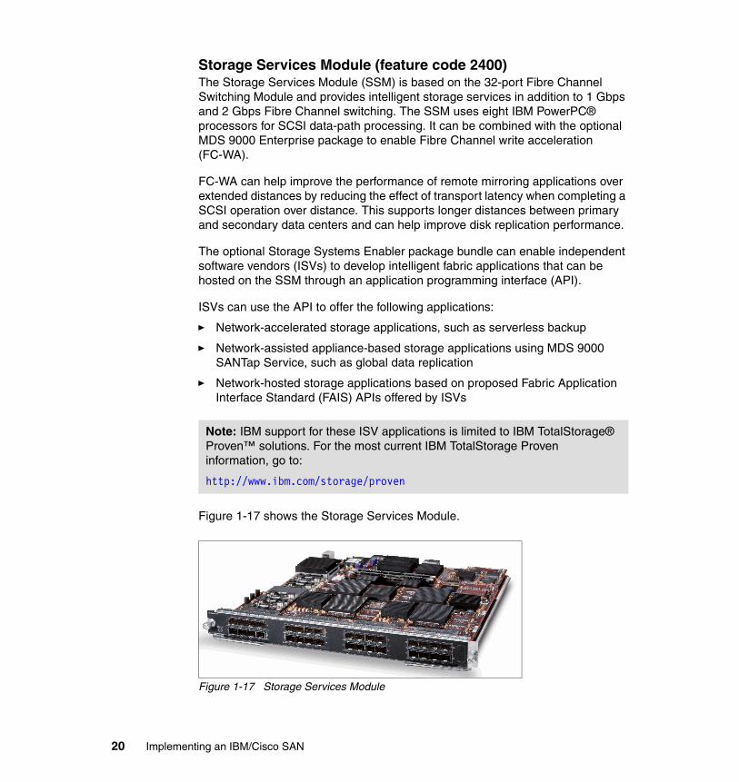
Storage Services Module (feature code 2400)The Storage Services Module (SSM) is based on the 32-port Fibre Channel Switching Module and provides intelligent storage services in addition to 1 Gbps and 2 Gbps Fibre Channel switching. The SSM uses eight IBM PowerPC® processors for SCSI data-path processing. It can be combined with the optional MDS 9000 Enterprise package to enable Fibre Channel write acceleration (FC-WA).
FC-WA can help improve the performance of remote mirroring applications over extended distances by reducing the effect of transport latency when completing a SCSI operation over distance. This supports longer distances between primary and secondary data centers and can help improve disk replication performance.
The optional Storage Systems Enabler package bundle can enable independent software vendors (ISVs) to develop intelligent fabric applications that can be hosted on the SSM through an application programming interface (API).
ISVs can use the API to offer the following applications:
� Network-accelerated storage applications, such as serverless backup
� Network-assisted appliance-based storage applications using MDS 9000 SANTap Service, such as global data replication
� Network-hosted storage applications based on proposed Fabric Application Interface Standard (FAIS) APIs offered by ISVs
Figure 1-17 shows the Storage Services Module.
Figure 1-17 Storage Services Module
Note: IBM support for these ISV applications is limited to IBM TotalStorage® Proven™ solutions. For the most current IBM TotalStorage Proven information, go to:
http://www.ibm.com/storage/proven
20 Implementing an IBM/Cisco SAN

The 32-port Advanced Services ModuleThe Cisco MDS 9000 family 32-Port Fibre Channel Advanced Services Module enables pooling of heterogeneous storage for increased storage utilization, simplified storage management, and reducing total cost of storage ownership.
The Advanced Services Module incorporates all the capabilities of the Cisco MDS 9000 family 32-Port Fibre Channel Switching Module and also provides scalable, in-band storage virtualization services. Combining a highly distributed processing architecture and integrated VERITAS Storage Foundation for Networks software, the Cisco Advanced Services Module delivers virtualization performance, which can be scaled by simply adding modules anywhere in the fabric to meet the performance needs of even the largest enterprises.
The Cisco Advanced Services Module is available in a 32-port configuration and accepts 2 Gbps Fibre Channel small form-factor pluggable (SFP) optical modules as MDS 9000 family Fibre Channel switching modules. Figure 1-18 shows the 32-port Advanced Services Module.
Figure 1-18 The 32-port Advanced Services Module
The 4-port 10 Gbps Switching Module (feature code 2404)The MDS 9000 family 4-port 10 Gbps Fibre Channel Switching Module delivers uncompromising performance with 10 Gbps link bandwidth, 80 Gbps of continuous aggregate bandwidth per module, and the intelligence and advanced features required to make multilayer storage area networks a reality. The 4-port 10 Gbps Fibre Channel Switching Module includes hardware-enabled innovations designed to dramatically improve performance, scalability, security, and manageability of storage networks, resulting in increased utility and lower total cost of ownership (TCO). The 4-port 10 Gbps Fibre Channel Module is hot-swappable, and individual ports can be configured with shortwave or long-wave X2 optical transceivers for connectivity of up to 10 kilometers. Up to 250 buffer credits per port are supported for maximum extensibility without requiring additional licensing. Ultrahigh per-port bandwidth makes the 4-port 10 Gbps Fibre Channel Switching Module ideal for Inter-Switch Link (ISL) connectivity, both within the data center and between data centers across metro optical networks.
Chapter 1. Product introduction 21

The 4-port 10 Gbps Fibre Channel Switching Model is compatible with all MDS 9500 Series Multilayer Directors, as well as MDS 9216A and MDS 9216i multilayer fabric switches, providing outstanding value and investment protection. Figure 1-19 shows a MDS 9000 family 4-port 10 Gbps Fibre Channel Switching Module.
Figure 1-19 4-port 10 Gbps Switching Module
The 12-port 4 Gbps Switching Module (feature code 2412)The 12-port 4 Gbps Switching Module is ideal for attachment to the highest performance 4 Gbps-enabled storage and for ISL connections. The 12-port 4 Gbps Switching Module can deliver up to 96 Gbps of full duplex bandwidth. Figure 1-20 shows the 12-port Switching Module.
Figure 1-20 Twelve-port Switching Module
22 Implementing an IBM/Cisco SAN

The 24-port 4 Gbps Switching Module (feature code 2424)The 24-port 4 Gbps Switching Module delivers an ideal balance of performance and scalability. The twenty-four 4 Gbps ports deliver up to 96 Gbps of full duplex bandwidth. Bandwidth is allocated across four 6-port port groups, providing 24 Gbps of full-duplex bandwidth per port group. Port bandwidth reservation enables switching bandwidth to be dedicated to a port, providing flexibility to optimize high-demand ports such as ISLs. Figure 1-21 shows the 24-port Switching Module.
Figure 1-21 Twenty-four-port 4 Gbps Switching Module
Chapter 1. Product introduction 23

The 48-port 4 Gbps Switching Module (feature code 2448)The 48-port 4 Gbps Switching Module delivers up to 96 Gbps of total bandwidth. Bandwidth is allocated across four 12-port port groups, providing 24 Gbps bandwidth per port group. Port bandwidth reservation enables switching bandwidth to be dedicated to a port, providing flexibility to optimize high-demand ports such as ISLs. Figure 1-22 shows the 48-port 4 Gbps Switching Module.
Figure 1-22 Forty-eight-port 4 Gbps Switching Module
The MDS 9000 18+4 Multiservice Module (feature code 2450)The MDS 18+4 Multiservice Module offers eighteen 4 Gbps Fibre Channel ports and four Gigabit Ethernet IP storage services ports. It is supported in the MDS 9200 Series Switches and MDS 9500 Series Directors.
The MDS 18+4 Multiservice Module provides multiprotocol capabilities integrating, in a single-form-factor Fibre Channel:
� Fibre Channel over IP (FCIP)� Small Computer System Interface over IP (iSCSI)� IBM Fiber Connectivity (FICON)� FICON Control Unit Port (CUP) management� Switch cascading
24 Implementing an IBM/Cisco SAN

It uses knowledge of IP networks to deliver outstanding SAN extension performance, minimizing latency for disk and tape with FCIP acceleration features including FCIP write acceleration and FCIP tape write and read acceleration. Figure 1-23 shows the MDS 9000 18+4 Multiservice Module.
Figure 1-23 MDS 9000 18+4 Multiservice Module
The MDS 9000 18+4 Multiservice FIPS Module The Cisco MDS 9000 family 18/4-Port Multiservice Federal Information Processing Standards (FIPS) Module, a FIPS 140-2 Level 3 compliant version of the Cisco MDS 9000 family 18/4-Port Multiservice Module, is offered to provide added security to meet regulatory and industry requirements. FIPS Level 3 certification requires enhanced physical security, including a hard, opaque potting material to deter unauthorized access and tampering. Figure 1-24 shows the MDS 9000 18+4 Multiservice FIPS Module.
Figure 1-24 MDS 9000 18+4 Multiservice FIPS Module
Chapter 1. Product introduction 25

Buffer creditsBuffer credits affect the number of input/outputs (I/Os) that can be sent before an acknowledgement is received. In extended Fibre Channel networks, you need more buffer credits to keep the pipe filled because the latency has increased.
Each target-optimized port supports 255 buffer credits, and host-optimized ports support 12 buffer credits per port. On the 14+2 line card, up to 3,500 buffer credits can be assigned to a single port if you are willing to sacrifice buffers on other ports and shut down three ports on the quad controlled by that ASIC. A maximum of 1500 buffer credits can be configured if the additional three ports are left enabled.
1.1.12 Generation 3 optional modules
Cisco now offers new Generation 3 line cards based on 8G technology.
New Gen3 cards work with all MDS 9500 Multilayer Directors and with MDS 9222i switches, as shown in Table 1-5.
Table 1-5 Generation 3 line cards
The allowed configurations for the Generation 3 line cards are:
� 24-port 8 Gbps Fibre Channel Switching Module (96 Gbps total). This module has eight port groups and each port group has three ports:
– One dedicated 8 Gbps plus two shared 8 Gbps (4:1).
– One dedicated 8 Gbps plus one dedicated 4 Gbps plus one shared 8 Gbps (10:1).
– Two dedicated 4 Gbps plus one shared 8 Gbps (with 2:1 oversubscription).
– Three dedicated 4 Gbps.
Note: Generation 3 cards can work only with Supervisor-2 modules, and the NX-OS firmware version 4.x is required.
Module 9513 9509 9506 922i 9216A 9216i
48-port 8 Gbps Fibre Channel switching module
X X X
24-port 8 Gbps Fibre Channel switching module
X X X
44/4-port 8 Gbps Host-Optimized Fibre Channel switching module
X X X X
26 Implementing an IBM/Cisco SAN

– Three shared 8 Gbps (with 2:1 oversubscription). This is the default setup.
� 48-port 8 Gbps Fibre Channel Switching Module (96 Gbps). This module has eight port groups and each port group has six ports:
– One dedicated 8 Gbps plus five shared 8 Gbps (10:1).
– Two dedicated 4 Gbps plus four shared 4 Gbps (with 4:1 oversubscription).
– One dedicated 4 Gbps plus three dedicated 2 Gbps plus two shared 4 Gbps (with 4:1 oversubscription).
– Six dedicated 2 Gbps.
– Six shared 8 Gbps (with 4:1 oversubscription). This is the default setup.
� 4/44-port 8 Gbps Host-Optimized Fibre Channel Switching Module (48 Gbps). This module has four port groups and each port group has 12 ports:
– One dedicated 8 Gbps plus 11 shared 4 Gbps (with 10:1 oversubscription).
– One dedicated 4 Gbps plus three dedicated 2 Gbps plus two shared 4 Gbps (with 2:1 oversubscription).
– Twelve dedicated 1 Gbps.
– Twelve shared 4 Gbps (with 5:1 oversubscription). This is the default setup.
1.1.13 Management tools
For switch and fabric management of the MDS 9000 family, both a command-line interface (CLI) and a graphical user interface (GUI) are available. The CLI uses Telnet, SSH, or a serial console, while the GUI-based Fabric Manager toolset uses SNMP when accessing the switches.
Fabric Manager 3.xFabric Manager is a network management toolset, using SNMPv3 (SNMP Versions 1 and 2 are also supported) when communicating with the MDS 9000 family switches (and third-party switches), providing a GUI to manage and perform real-time monitoring.
The toolset consists of the following components:
� Fabric Manager Server
The Fabric Manager Server is the server component of the toolset and must be started prior to using Fabric Manager. When launching the GUI for the first time, the Fabric Manager Server is installed as a service on Windows® (daemon on Linux or Solaris™).
Chapter 1. Product introduction 27

� Device Manager
The Device Manager is a switch-embedded Java™ application that is installed (and updated automatically) by Java Web start. While the Device Manager is somewhat complimentary to the Fabric Manager, the difference is that with Device Manager you manage a single switch, whereas with Fabric Manager you can manage multiple switches.
� Fabric Manager Client
The Fabric Manager Client is a switch-embedded Java application that is installed (and updated automatically) by Java Web start. With the Fabric Manager, switch and fabric configurations are performed.
� Performance Manager
Performance Manager is used for historic network device statistics collection and graphical presentation (in a Web browser), presenting recent statistics in detail and older statistics in summary. Performance Manager is set up using a configuration wizard.
Fabric Manager 4.xThe new version of Fabric Manager 4.x will be released along with a new version of the MDS operating system NX-OS 4.x. All features will be available in the Cisco MDS NX-OS 4.x and SAN-OS Release 3.x.
Table 1-6 shows the new and changed features of Fabric Manager for SAN-OS 3.x and NX-OS 4.x.
Table 1-6 Features of the Fabric Manager 4.x for SAN-OS 3.x and NX-OS 4.x.
Feature Description Changed in Release
Supported platforms Information and FM Express Install
The server platforms supported for Cisco Fabric Manager have been revised.
4.1.(X)
Inventory Report Enhancements
The FMS inventory switch detail report has been enhanced to include a number of summary statistics useful for creating a more comprehensive SAN health report.
4.1.(X)
Server Admin Tool The Server Admin perspective view limits the scope of Fabric Manager to Flex Attach configuration and relevant data.
4.1.(X)
DPVM Wizard New pages added. 4.1.(X)
Flex Attach Configuration by Server Administrators
Procedures to use the Flex Attach wizards for pre-configuring all or selected ports, moving a server to a different port or switch, and replacing a server in the same or a different port or switch.
4.1.(X)
28 Implementing an IBM/Cisco SAN

Cisco Fabric Manager 4.x has been tested with the following software:
� Operating systems
– Windows 2003 SP2, Windows XP SP2, Windows XP SP3, Windows Vista® SP1 (Enterprise edition)
– Red Hat Enterprise Linux AS Release 4
– Solaris (SPARC) 8, 9 and 10
– VMWare ESX Server 3.5
� Java
– Sun™ JRE™ and JDK™ 1.5(x) and 1.6(x) supported
– Java Web Start 1.5 and 1.6
� Browsers
– Internet Explorer® 6.x and 7.0
– Firefox 1.5 and 2.0
– Mozilla 1.7 (packaged with Solaris 9)
� Databases
– Oracle® Database 10g Express, Oracle Enterprise Edition 10g
– PostgreSQL 8.2 (Windows and Red Hat Enterprise Linux AS Release 4)
– PostgreSQL 8.1 (Solaris 8, 9 and 10)
IP Static Peers for CFS over IP
Added IP static peers configuration steps for CFS distribution over IP.
4.1.(X)
Generation 3 48-Port, 24-Port, and 4/44-Port 8 Gbps Fibre Channel modules configuration
Added configuration guidelines that include port groups, port rate modes, BB_credit buffer allocation, port speed configuration, over subscription ratio restrictions, combining with earlier generation modules, upgrade and downgrade considerations, cross bar management, port channel interface configuration, example configurations, and default settings.
4.1.(X)
Call Home Added the delayed traps enhancements. 4.1.(X)
Performance Manager
Added the flow creation wizard for performance manager. 4.1.(X)
Feature Description Changed in Release
Chapter 1. Product introduction 29

� Security
– Cisco ACS 3.1 and 4.0
– PIX Firewall
– IP tables
– SSH v2
– Global Enforce SNMP Privacy Encryption
– HTTPS
Minimum hardware requirements for Fabric Manager 4.xFor a PC running Fabric Manager Server on large fabrics (1,000 or more end devices), we recommend using a dual core/dual CPU high-speed system with 2 GB of RAM and 10 GB of free disk space.
CLIFrom the CLI interface we can perform fabric and switch management, while the CLI parser provides both command help and command completion. The keyboard sequence stores previously used commands in the buffer history. Performing ongoing fabric and switch management using the GUI is somewhat more intuitive, and most switch commands are available, though when it comes to troubleshooting, comparably the CLI is a more powerful interface.
LicensingThe licensing model for the MDS 9000 family consists of two options:
� Feature-based licensing, which implies a per-switch cost, for features that apply to the entire switch
� Module-based licensing for features that require a specific hardware module such as the IPS module
Note: Internet Explorer 7.0 is not supported on Windows 2000 SP4.
30 Implementing an IBM/Cisco SAN

The standard license package, which is included with every MDS 9000 family switch (base configuration) includes standard SAN software features, while some advanced features are add-on options bundled in the following license packages and must be acquired separately:
� Enterprise Package (ENTERPRISE_PKG)
This package mainly consists of two types of advanced features:
– Advanced Traffic engineering features, which are:
• Inter-VSAN routing (IVR)
• Quality of service (QoS)
• Extended credits
• Fibre Channel write acceleration and SCSI Flow statistics at LUN level (only available on SSM an ASM)
– Enhanced Network Security Features, which are:
• Fibre Channel Security Protocol (FC-SP) providing switch-to-switch and switch-to-host authentication
• Diffie-Hellman Challenge Handshake Authentication Protocol (DH-CHAP), which can be combined with RADIUS or TACACS+ for remote authentication
• Hardware-enforced LUN zoning
• Read-only zones
• Port Security, mapping a specific device to be the only one able to access the fabric on a given port
• VSAN-based access control
• IPsec, available for both FCIP and iSCSI
The license is acquired on a per-switch basis, though some features require that all switches in the fabric have the license package.
� SAN Extension over IP Package (SAN_EXTN_OVER_IP)
This package enables integrated Fibre Channel Interface Protocol (FCIP) and must be acquired on a per-module basis. IVR for FCIP is also included with this license.
� Mainframe Package (MAINFRAME_PKG)
This package enables IBM Fibre Connection (FICON) support and must be acquired on a per-switch basis.
� Fabric Manager Server Package (FMSERVER_PKG)
This package extends the standard Fabric Manager toolset, providing historical performance monitoring, centralized management services, and
Chapter 1. Product introduction 31

advanced application integration. This package is acquired on a per-switch basis.
� MDS9000 Storage Service Enabler Package
This package is currently not sold by IBM and is not discussed further.
When buying the MDS 9000 family switch, the standard license package is always included. To see which other licenses are available with a specific switch type, refer to Table 1-7.
Table 1-7 MDS 9000 family licensing options
Note: For a complete list of features within each license package, see the respective license package fact sheets:
http://www.cisco.com/en/US/products/hw/ps4159/ps4358/products_data_sheets_list.html
Switch model ENTERPRISE SAN_EXTN_OVER_IP
FMSERVER MAINFRAME
MDS 9020 Optional N/A Optional N/A
MDS 9120 Optional N/A Optional N/A
MDS 9124 Optional N/A Optional N/A
MDS 9134 Optional N/A Optional Optional
MDS 9140 Optional N/A Optional N/A
MDS 9216 (A/i) Optional Optional for 9216a Optional Optional
MDS 9222i Optional Optional Optional Optional
MDS 9506 Optional Optional Optional Optional
MDS 9509 Optional Optional Optional Optional
MDS 9513 Optional Optional Optional Optional
32 Implementing an IBM/Cisco SAN

1.1.14 Support matrixes for the SAN-OS 3.x and NX-OS 4.x
In Figure 1-25 we show the support matrix for NX-OS 4.x code.
Figure 1-25 Support matrix for NX-OS 4.x code
Chapter 1. Product introduction 33

In Figure 1-26 we show the support matrix for SAN-OS 3.x and NX-OS 4.x code.
Figure 1-26 Support matrix for SAN-OS 3.x and NX-OS 4.x code
34 Implementing an IBM/Cisco SAN

Chapter 2. Ports and modules
In this chapter we discuss the Cisco port modes in MDS directors and switches.
2
© Copyright IBM Corp. 2009. All rights reserved. 35

2.1 Port addressing and port modes
The Fibre Channel ports in the Cisco MDS 9000 family are numbered with addresses in the form of fc<slot>/<port>, where <slot> is the slot number of the line card (1–9) and <port> is the port number on the line card (1–32). For example, the first port of the line card in slot 1 is fc1/1, and the seventh port of the line card in slot 3 is fc3/7.
2.1.1 Fibre Channel IDs and persistent FCIDs
Contrary to other switch manufacturers, with the Cisco MDS 9000 family there is no fixed correlation between physical Fibre Channel ports and Fibre Channel IDs (FCID). This is necessary to allow intermixing of line cards with different numbers of ports, while being able to utilize all port addresses, to allow both fabric and loop devices to coexist, and also to allow switches larger than 256 ports.
The primary reason for persistent FCIDs is to enable customers to move devices within a switch without having to rebind the disk. This could be used in the case of a linecard or SFP failure, for example.
The following considerations apply to the FCID assignment for any VSAN:
� When an N_Port or NL_Port logs into the switch, it is assigned an FCID.
� N_Ports receive the same FCID if disconnected and reconnected to any port within the same switch, and within the same VSAN.
� NL_Ports receive the same FCID only if reconnected to the same port within the same switch where the port was originally connected.
If the persistent FCIDs feature is not enabled for a VSAN, the following considerations apply:
� The WWN of the N_Port or NL_Port and the assigned FCID are stored in a volatile cache, and are not saved across switch reboots.
� The switch preserves the binding of FCID to WWN on a best-effort basis.
� The volatile cache has room for a maximum of 4,000 entries, and if the cache gets full, the oldest entries are overwritten.
36 Implementing an IBM/Cisco SAN

If the persistent FCID feature is enabled for a VSAN, the following considerations apply:
� The FCID-to-WWN mapping of the WWNs currently in use is stored to a nonvolatile database and is saved across reboots.
� The FCID-to-WWN mapping of any new device connected to the switch is automatically stored in the non-volatile database.
� You can manually configure the FCID-to-WWN mappings if necessary.
Example 2-1 Persistent FCID enabled for VSAN 10
mds9222i-1# show fcdomain vsan 10The local switch is the Principal Switch.
Local switch run time information: State: Stable Local switch WWN: 20:0a:00:0d:ec:82:3d:01 Running fabric name: 20:0a:00:0d:ec:82:3d:01 Running priority: 10 Current domain ID: 0x0a(10)
Local switch configuration information: State: Enabled FCID persistence: Enabled Auto-reconfiguration: Disabled Contiguous-allocation: Disabled Configured fabric name: 20:01:00:05:30:00:28:df Optimize Mode: Disabled Configured priority: 10 Configured domain ID: 0x0a(10) (static)
Principal switch run time information: Running priority: 10
Note: If you attach AIX or HP-UX hosts to a VSAN, you must have persistent FCIDs enabled for that VSAN. This is because these operating systems use the FCIDs in device addressing. If the FCID of a device changes, the operating system considers it to be a new device, and gives it a new name.
In general, we recommend enabling persistent FCIDs for your VSANs unless you have specific requirements that do not comply with persistent FCIDs. Example 2-1 shows persistent FCID enabled for VSAN 10.
Chapter 2. Ports and modules 37

2.1.2 Port operational modes
The Fibre Channel ports in the Cisco MDS 9000 family can operate in several modes. The operational modes are described in Table 2-1.
Table 2-1 Fibre Channel port operational modes
Mode Description
E_Port An expansion port (E_Port) interconnects two Fibre Channel switches, forming an ISL between an E_Port in each switch. The ISL belongs to a single VSAN and can also be connected to third-party switches.
F_Port A fabric port (F_Port) connects the switch to a N_Port in a host or storage device using a point-to-point link. Only one N_Port can connect to the F_Port.
FL_Port A fabric loop port (FL_Port) connects the switch to a public FC-AL loop. Only one FL_Port can be operational in a single FC-AL loop at any given time.
TE_Port A trunking E_Port (TE_Port) interconnects two Fibre Channel switches, forming an extended ISL (EISL) between a TE_Port in each switch. The EISL can multiplex the traffic of several VSANs.The EISL is currently only available in the Cisco MDS 9000 family of switches.
TL_Port A translative loop port (TL_Port) connects the switch to a private FC-AL loop.
B_Port A bridge port (B_Port) is used to connect some SAN extender devices to the switch, instead of E_Port.
Fx_Port A Fx_Port can operate as either F_Port or FL_Port, depending on the device connected to it. The port mode is determined during interface initialization.
Auto A port configured as auto can operate as E_Port, F_Port, FL_Port, or TE_Port, depending on the device connected to it. The port mode is determined during interface initialization.
38 Implementing an IBM/Cisco SAN

SD_Port A SPAN destination port (SD_Port) acts as a snooper port, allowing the monitoring of the switch traffic with a standard Fibre Channel analyzer. In SPAN destination port (SD port) mode, an interface functions as a switched port analyzer (SPAN).The SPAN feature is specific to switches in the Cisco MDS 9000 family. It monitors network traffic that passes though a Fibre Channel interface. This monitoring is done using a standard Fibre Channel analyzer (or a similar switch probe) that is attached to an SD port. SD ports do not receive frames. They merely transmit a copy of the source traffic. The SPAN feature is non-intrusive and does not affect switching of network traffic for any SPAN source ports
ST_Port In the SPAN tunnel port (ST port) mode, an interface functions as an entry point port in the source switch for the RSPAN Fibre Channel tunnel. The ST port mode and the remote SPAN (RSPAN) feature are specific to switches in the Cisco MDS 9000 family. When configured in ST port mode, the interface cannot be attached to any device, and thus cannot be used for normal Fibre Channel traffic.
NP_Port An NP port is a port on a device that is in NPV mode and connected to the core switch via an F port. NP ports behave like N ports except that in addition to providing N port behavior, they also function as proxies for multiple physical N ports.
Mode Description
Chapter 2. Ports and modules 39

Figure 2-1 shows an example of the port types that are available with the Cisco MDS 9000 family of products (ST_Port not shown).
Figure 2-1 Cisco MDS 9000 family port types
40 Implementing an IBM/Cisco SAN

The port mode can be changed for any given port through Device Manager, as shown in Figure 2-2 and Figure 2-3 on page 42.
Figure 2-2 Port configuration selection
Example 2-2 shows port mode configuration from the command-line interface.
Example 2-2 Port mode selection from the command-line interface
mds9222i-1(config-if)# switchport modeE F FL Fx NP SD ST TL auto
Chapter 2. Ports and modules 41

Figure 2-3 shows the Device Manager port configuration for the 8 Gbps port.
Figure 2-3 Device Manager port configuration window for the 8 Gbps port
42 Implementing an IBM/Cisco SAN

Figure 2-4 shows the Device Manager port summary window. It shows port mode for all ports and the WWNs of connected devices. There are statistics for transmission, errors, and discards. Above the list there is current CPU, memory, and flash utilization information and thresholds. This view can be filtered for any particular VSAN.
Figure 2-4 Device Manager port summary window
Chapter 2. Ports and modules 43

When we choose a port on a Gen 2 or Gen 1 module we will get a similar window to those shown before, but some options will be grayed out, as shown in Figure 2-5.
Figure 2-5 Device Manager port configuration window for the Gen 2 line card
2.2 Configuration guidelines for Gen 2 and Gen 3
Depending on the type of MDS 9000 device, we can have from one line card in the MDS9222i, up to 11 line cards in the MDS 9513 Director. Depending on the type of the module, we can configure or control the number of options and parameters. There is a set of parameters that are different for different types of line cards.
44 Implementing an IBM/Cisco SAN

For all of the line cards we can check, view, or perform configuration steps using the CLI or the GUI. In most cases it is easier, and quicker, to use the GUI as shown in Figure 2-6 and in Figure 2-7 for a Gen 3 line card.
Figure 2-6 Configuration tasks for MDS 9000 line cards
Figure 2-7 Configuration tasks for the MDS 9000 Gen 3 line card
Chapter 2. Ports and modules 45

Standard administration tasks for MDS line cardsFor most of the line cards we can perform the following administration tasks:
1. Check the status and configure a line card as shown in Figure 2-8 and in Figure 2-9.
Figure 2-8 Check the status of the line card
Figure 2-9 Configure the line card
2. Reset the module.
3. Show port resources, as shown in Example 2-3.
Example 2-3 Show port resources command from the CLI
mds9222i-2# show port-resources module 2Module 2 Available dedicated buffers are 3564Port-Group 1
46 Implementing an IBM/Cisco SAN

Total bandwidth is 12.8 Gbps Total shared bandwidth is 4.8 Gbps Allocated dedicated bandwidth is 8.0 Gbps -------------------------------------------------------------------- Interfaces in the Port-Group B2B Credit Bandwidth Rate Mode Buffers (Gbps) -------------------------------------------------------------------- fc2/1 125 8.0 dedicated fc2/2 32 4.0 shared fc2/3 32 4.0 shared fc2/4 32 4.0 shared fc2/5 32 4.0 shared fc2/6 32 4.0 shared fc2/7 32 4.0 shared fc2/8 32 4.0 shared fc2/9 32 4.0 shared fc2/10 32 4.0 shared fc2/11 32 4.0 shared fc2/12 32 4.0 sharedPort-Group 2 Total bandwidth is 12.8 Gbps Total shared bandwidth is 8.8 Gbps Allocated dedicated bandwidth is 4.0 Gbps -------------------------------------------------------------------- Interfaces in the Port-Group B2B Credit Bandwidth Rate Mode Buffers (Gbps) -------------------------------------------------------------------- fc2/13 32 4.0 shared fc2/14 125 4.0 dedicated fc2/15 32 4.0 shared fc2/16 32 4.0 shared fc2/17 32 4.0 shared fc2/18 32 4.0 shared fc2/19 32 4.0 shared fc2/20 32 4.0 shared fc2/21 32 4.0 shared fc2/22 32 4.0 shared fc2/23 32 4.0 shared fc2/24 32 4.0 sharedPort-Group 3 Total bandwidth is 12.8 Gbps Total shared bandwidth is 4.8 Gbps Allocated dedicated bandwidth is 8.0 Gbps -------------------------------------------------------------------- Interfaces in the Port-Group B2B Credit Bandwidth Rate Mode Buffers (Gbps) -------------------------------------------------------------------- fc2/25 125 8.0 dedicated fc2/26 32 4.0 shared
Chapter 2. Ports and modules 47

fc2/27 32 4.0 shared fc2/28 32 4.0 shared fc2/29 32 4.0 shared fc2/30 32 4.0 shared fc2/31 32 4.0 shared fc2/32 32 4.0 shared fc2/33 32 4.0 shared fc2/34 32 4.0 shared fc2/35 32 4.0 shared fc2/36 32 4.0 sharedPort-Group 4 Total bandwidth is 12.8 Gbps Total shared bandwidth is 4.8 Gbps Allocated dedicated bandwidth is 8.0 Gbps -------------------------------------------------------------------- Interfaces in the Port-Group B2B Credit Bandwidth Rate Mode Buffers (Gbps) -------------------------------------------------------------------- fc2/37 125 8.0 dedicated fc2/38 32 4.0 shared fc2/39 32 4.0 shared fc2/40 32 4.0 shared fc2/41 32 4.0 shared fc2/42 32 4.0 shared fc2/43 32 4.0 shared fc2/44 32 4.0 shared fc2/45 32 4.0 shared fc2/46 32 4.0 shared fc2/47 32 4.0 shared fc2/48 32 4.0 shared
4. Check the oversubscription as shown in Figure 2-10.
Figure 2-10 Checking the oversubscription status from the Device Manager
48 Implementing an IBM/Cisco SAN
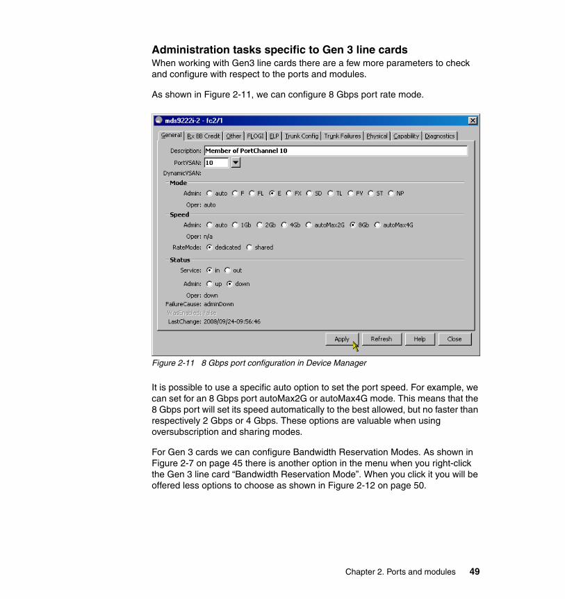
Administration tasks specific to Gen 3 line cardsWhen working with Gen3 line cards there are a few more parameters to check and configure with respect to the ports and modules.
As shown in Figure 2-11, we can configure 8 Gbps port rate mode.
Figure 2-11 8 Gbps port configuration in Device Manager
It is possible to use a specific auto option to set the port speed. For example, we can set for an 8 Gbps port autoMax2G or autoMax4G mode. This means that the 8 Gbps port will set its speed automatically to the best allowed, but no faster than respectively 2 Gbps or 4 Gbps. These options are valuable when using oversubscription and sharing modes.
For Gen 3 cards we can configure Bandwidth Reservation Modes. As shown in Figure 2-7 on page 45 there is another option in the menu when you right-click the Gen 3 line card “Bandwidth Reservation Mode”. When you click it you will be offered less options to choose as shown in Figure 2-12 on page 50.
Chapter 2. Ports and modules 49

The options to configure are dependent on the type of Gen3 card. This applies to the 44/4-port 8 Gbps Host-Optimized Fibre Channel switching module in our MDS9222i:
� Dedicated 2G on the first port of each group, remaining ports 4G shared� Dedicated 8G on the first port of each group, remaining ports 4G shared� Shared AutoMax4G on all ports (initial & default settings)
The 44/4-port 8 Gbps Host-Optimized Fibre Channel switching module has 4 port groups and each port group has 12 ports.
Figure 2-12 Bandwidth Reservation Config for Gen 3 line cards
There are three Gen 3 line cards available at the time of writing and all of them follow the same rules with respect to the ports and modules configuration and administration.
50 Implementing an IBM/Cisco SAN

Chapter 3. Operating system
In this chapter we discuss the Cisco SAN-OS and NX-OS operating systems.
3
© Copyright IBM Corp. 2009. All rights reserved. 51

3.1 System memory areas
The Cisco MDS contains an internal bootflash used for holding the current bootable images, kickstart and system. License files are also stored here, but the bootflash can also be used for storing any file, including copies of the startup config.
MDS 9500 supervisors also have an external bootflash memory slot called Slot0: that is used for transferring image files between switches.
The system RAM memory is used by the Linux operating system and a Volatile: file system for storing temporary files. Any changes made to the switch operating parameters or configuration are instantly active and held in the running configuration.
All data stored in RAM will be lost when the MDS is rebooted, so an area of non-volatile RAM (NVRAM) is used for the storage of critical data. The most critical of these would be the running configuration for the switch. The running configuration should be saved to the Startup-Configuration in NVRAM using the CLI command copy run start so that the configuration can be preserved during a switch reboot.
The MDS Cisco 9000 family switches have three main memory areas, as shown in Figure 3-1.
Figure 3-1 MDS Cisco 9000 memory areas
52 Implementing an IBM/Cisco SAN

During the switch boot process, it is essential that the switch knows where to find the kickstart and system images and what they are called. Two boot parameters are held in NVRAM:
� Boot system bootflash: <system>.img� Load kickstart bootflash: <kickstart>.img
An example of boot parameters stored in NVRAM is shown in Example 3-1.
Example 3-1 Boot parameters from NVRAM
mds9222i-1# show running-config---- truncate ----switchname mds9222i-1boot kickstart bootflash:/m9200-s2ek9-kickstart-mz.4.1.1.binboot system bootflash:/m9200-s2ek9-mz.4.1.1.bin---- truncate ----
3.1.1 Boot sequence
SAN-OS is the common operating system for all switches in the MDS9000 SAN switch family. Each switch is shipped with the latest MDS SAN-OS, which consists of a kickstart and a system image. Starting from release 4.x SAN-OS, it will be rebranded to NX-OS. The newest MDS9000 devices will be shipped with the NX-OS 4.x operating system based on the same source code tree.
Chapter 3. Operating system 53

To understand the concept of kickstart and system images, we briefly explain the boot sequence for a MDS 9000 family switch, as shown in Figure 3-2:
1. The BIOS performs HW component tests (runs POST) and loads Bootloader
2. Bootloader gets kickstart boot parameters from the NVRAM, verifies the kickstart image, and loads it from the bootflash. After that we will get a loader prompt Loader>prompt.
3. The kickstart image loads the Linux kernel and drivers from the bootflash and gets system boot parameters from NVRAM. It verifies the system image and loads it. After that we will get a Switch(Boot)# prompt.
4. The system image reads the startup configuration file, loads SAN-OS/NX-OS, checks file systems, and loads startup-config. When the system image has loaded you can access and manage the switch using the management interface Switch#prompt.
Figure 3-2 Regular boot sequence
The kickstart and system image must be available for the switch to boot, and therefore it is placed in the bootflash. It is possible to boot from an external
Note: If the boot parameters are missing or have an incorrect name or location, then the boot process will fail at the last stage. If this happens, then you must recover from the error and reload the switch. The install all command is a script that greatly simplifies the boot procedure and checks for errors and the upgrade impact before proceeding.
54 Implementing an IBM/Cisco SAN

kickstart image placed on a TFTP server, although this requires manual intervention. This is only used when recovering from corrupted boot images, and the process is to copy the kickstart and system image to the bootflash (after verifying that the switch can boot from the kickstart image on the TFTP server).
3.1.2 Upgrade prerequisites When upgrading the SAN-OS or NX-OS on a Cisco MDS 9000 family switch, you must specify the variables that direct the switch to the images (kickstart or system).
Verify the following prerequisites prior to upgrading the software images:
� Scheduling
Verify that the fabric is stable and steady, while ensuring that no switch or network configurations are performed when you plan to upgrade the switch, since all configurations are disallowed while the upgrade is running.
� Space
Verify that there is enough space available where you intend to copy the new software images (this being the active and the standby supervisor bootflash). Use the command-line interface (CLI) to dir bootflash to verify that the required space is available, as shown in Example 3-2.
Example 3-2 Listing files on bootflash
mds9222i-1# dir bootflash: 1567 Sep 18 23:02:05 2008 FOX1216GP0C.lic 25 Sep 11 02:16:32 2008 cpu_logfile 1024 Sep 11 06:40:00 2008 epld_dir/ 46080 Sep 17 02:02:16 2008 lost+found/ 3757210 Sep 11 02:06:49 2008 m9000-epld-4.1.1.img 19542528 Sep 17 02:01:58 2008 m9200-s2ek9-kickstart-mz.4.1.1.bin 101905006 Sep 17 02:01:51 2008 m9200-s2ek9-mz.4.1.1.bin 106106231 Sep 18 00:07:29 2008 m9200-s2ek9-mzg.4.1.0.182.bin 1024 Sep 11 02:16:33 2008 partner/
Usage for bootflash://sup-local 275624960 bytes used 71203840 bytes free 346828800 bytes total
Chapter 3. Operating system 55

� Hardware
Ensure that the switch is connected to a stable power source, as loss of power during the upgrade could potentially corrupt the image. An example command is shown in Example 3-3.
Example 3-3 Checking the status of the power modules
mds9222i-1# show environment powerPower Supply:Voltage: 42 Volts-----------------------------------------------------PS Model Power Power Status (Watts) (Amp)-----------------------------------------------------1 DS-CAC-845W 800.10 19.05 Ok2 DS-CAC-845W 800.10 19.05 Ok
Mod Model Power Power Power Power Status Requested Requested Allocated Allocated (Watts) (Amp) (Watts) (Amp)--- ------------------- ------- ---------- --------- ---------- ----------1 DS-X9222I-K9 209.16 4.98 209.16 4.98 Powered-Up2 DS-X9248-48K9 214.20 5.10 214.20 5.10 Powered-Upfan1 DS-2SLOT-FAN 47.88 1.14 47.88 1.14 Powered-Up
Power Usage Summary:--------------------Power Supply redundancy mode: RedundantPower Supply redundancy operational mode: Redundant
Total Power Capacity 800.10 W
Power reserved for Supervisor(s) 418.32 WPower reserved for Fan Module(s) 47.88 W
56 Implementing an IBM/Cisco SAN

Power currently used by Modules 214.20 W
-------------Total Power Available 119.70 W -------------
� Connectivity
Verify that you have connectivity to the server from which you are downloading the software images.
� Images
Verify that the specified system and kickstart images are compatible. If no kickstart image is specified, the running kickstart image is used. If a different system image is specified, you must verify that it is compatible with the running kickstart image.
When upgrading the SAN-OS or NX-OS on any Cisco MDS 9000 family switch running in production, we strongly recommend that you use the install all command, which provides a nondisruptive upgrade process.
For switches not running in production, you can alternatively perform the quick upgrade procedure using the reload command. This process is disruptive.
3.1.3 Install all
Using the install all command provides you with the ability to upgrade a switch in the least disruptive way. When invoked, the command first checks the image integrity, including the running kickstart and system images, and performs a platform validity check of the image to which you are upgrading. When the validation is performed, you are presented with an overview of the changes (and impact), and you are prompted to confirm the upgrade process to start (or cancel).
Important: If you issue the install all command on a switch that only has a single supervisor system with kickstart and system image changes, or on a dual supervisor system with incompatible system software images, then the process is disruptive.
Important: We strongly recommend having a copy of the switch configuration files on an external server or on any other external resource before starting the upgrade firmware process.
Chapter 3. Operating system 57

3.1.4 Quick upgrade
Performing a quick upgrade using the reload command is only recommended for switches not in production, while on completion the switch is rebooted. The process is to copy the kickstart and system image to the switch, set the boot variables, and issue the reload command. When completed, the switch is rebooted.
3.1.5 Manual upgrade
We only recommend performing a manual installation for experienced specialists who are completely familiar with switch configurations. For further details on how to perform manual upgrades, consult the Cisco MDS 9000 Family Configuration Guide:
http://www.cisco.com/en/US/products/ps5989/products_installation_and_configuration_guides_list.html
3.2 Upgrading the SAN-OS or NX-OS
In the topics that follow we describe how to upgrade the SAN-OS or NX-OS.
We upgrade the NX-OS to the latest released level. This can be done using either the CLI or the graphical user interface (GUI) (FM or DM). For completeness we show how to perform the upgrade using both the CLI and the GUI.
Note: We recommend that you always contact your IBM service representative prior to performing a SAN-OS or NX-OS upgrade, to review your software requirements based on your operating environment.
Note: For this book we used NX-OS Version 4.1(0.182) and NX-OS Version 4.1(1).
58 Implementing an IBM/Cisco SAN

3.2.1 Upgrading the SAN-OS or NX-OS using the CLI
To upgrade the SAN-OS or NX-OS using the CLI:
1. Check the current SAN-OS or NX-OS version.2. Check the free space of bootflash to copy files3. Copy files form the FTP server to CISCO bootflash.4. Back up the running configuration.5. Install SAN-OS using the command install all.6. Verify the switch version.
Prior to upgrading the switch, we first list the current SAN-OS or NX-OS version running on the switch, as shown in Example 3-4.
Example 3-4 Issuing show version before upgrade
mds9222i-1# show versionCisco Nexus Operating System (NX-OS) SoftwareTAC support: http://www.cisco.com/tacCopyright (c) 2002-2008, Cisco Systems, Inc. All rights reserved.The copyrights to certain works contained herein are owned byother third parties and are used and distributed under license.Some parts of this software are covered under the GNU PublicLicense. A copy of the license is available athttp://www.gnu.org/licenses/gpl.html.
Software BIOS: version 1.0.15 loader: version N/A kickstart: version 4.1(1) [build 4.1(0.182)] [gdb] system: version 4.1(1) [build 4.1(0.182)] [gdb] BIOS compile time: 07/16/08 kickstart image file is: bootflash:/m9200-s2ek9-kickstart-mzg.4.1.0.182.bin kickstart compile time: 10/12/2020 25:00:00 [08/15/2008 18:42:09] system image file is: bootflash:/m9200-s2ek9-mzg.4.1.0.182.bin system compile time: 12/25/2010 12:00:00 [08/15/2008 20:03:21]
Hardware cisco MDS 9222i ("4x1GE IPS, 18x1/2/4Gbps FC/Sup2") Motorola, e500v2 with 1036512 kB of memory. Processor Board ID JAE12088ZMT
Device name: mds9222i-1 bootflash: 1000440 kBKernel uptime is 0 day(s), 0 hour(s), 3 minute(s), 38 second(s)
Chapter 3. Operating system 59

Last reset at 970000 usecs after Wed Sep 17 00:31:49 2008
Reason: Reset Requested by CLI command reload System version: 4.1(1) Service:
After we have done that we verify that there is sufficient space on the supervisor bootflash, as shown in Example 3-5.
Example 3-5 Listing the bootflash
mds9222i-1# dir bootflash: 25 Sep 11 02:16:32 2008 cpu_logfile 1024 Sep 11 06:40:00 2008 epld_dir/ 46080 Sep 17 00:24:31 2008 lost+found/ 3757210 Sep 11 02:06:49 2008 m9000-epld-4.1.1.img 19542528 Sep 11 02:08:00 2008 m9200-s2ek9-kickstart-mz.4.1.1.bin 19560960 Sep 17 00:23:42 2008 m9200-s2ek9-kickstart-mzg.4.1.0.182.bin 101905006 Sep 11 02:15:15 2008 m9200-s2ek9-mz.4.1.1.bin 106106231 Sep 17 00:22:14 2008 m9200-s2ek9-mzg.4.1.0.182.bin 1024 Sep 11 02:16:33 2008 partner/
Usage for bootflash://sup-local 295262208 bytes used 51566592 bytes free 346828800 bytes total
Next we copy the NX-OS code from an FTP server to the bootflash: on the switch, as shown in Example 3-6.
Example 3-6 Copy NX-OS code to bootflash
mds9222i-1# copy ftp://9.43.86.49/jaco/4.1.1/m9200-s2ek9-kickstart-mz.4.1.1.bin bootflash:Enter username: jacoFile transfer in progress, please wait ...Password:mds9222i-1# copy ftp://9.43.86.49/jaco/4.1.1/m9200-s2ek9-mz.4.1.1.bin bootflash:Enter username: jaco
Note: Ensure that the FTP server is reachable in order to copy the required files. Firewalls may prevent you from reaching the FTP server.
60 Implementing an IBM/Cisco SAN

File transfer in progress, please wait ...Password:mds9222i-1#
Prior to starting the actual upgrade process we back up the running configuration to our FTP server, as shown in Example 3-7.
Example 3-7 Back up the running configuration
mds9222i-1# copy running-config ftp://9.43.86.49/jaco/backupEnter username: jacoPassword:*********mds9222i-1#
After backing up the configuration, start the upgrade using the install all command, as shown in Example 3-8.
Example 3-8 Upgrading the switch using the install all command
mds9222i-1# install all system bootflash:m9200-s2ek9-mz.4.1.1.bin kickstart bootflash:m9200-s2ek9-kickstart-mz.4.1.1.bin
Verifying image bootflash:/m9200-s2ek9-kickstart-mz.4.1.1.bin for boot variable "kickstart".[####################] 100% -- SUCCESS
Verifying image bootflash:/m9200-s2ek9-mz.4.1.1.bin for boot variable "system".[####################] 100% -- SUCCESS
Verifying image type.[####################] 100% -- SUCCESS
Extracting "system" version from image bootflash:/m9200-s2ek9-mz.4.1.1.bin.[####################] 100% -- SUCCESS
Extracting "kickstart" version from image bootflash:/m9200-s2ek9-kickstart-mz.4.1.1.bin.[####################] 100% -- SUCCESS
Tip: A best practice when performing configuration changes is to always save the running configuration to the startup configuration. By doing this you could also preserve previous startup configurations for two generations.
Note: We recommend verifying that the backup completed successfully, is readable, and is accessible.
Chapter 3. Operating system 61

Extracting "bios" version from image bootflash:/m9200-s2ek9-mz.4.1.1.bin.[####################] 100% -- SUCCESS
Extracting "slc2" version from image bootflash:/m9200-s2ek9-mz.4.1.1.bin.[####################] 100% -- SUCCESS
Performing Compact Flash and TCAM sanity test.[####################] 100% -- SUCCESS
Notifying services about system upgrade. [####################] 100% -- SUCCESS
Compatibility check is done:Module bootable Impact Install-type Reason------ -------- -------------- ------------ ------ 1 yes non-disruptive none 2 yes non-disruptive none
Do you want to continue with the installation (y/n)? [n] y
Install is in progress, please wait.
Setting boot variables.[####################] 100% -- SUCCESS
Performing configuration copy.[####################] 100% -- SUCCESS
Module 1: Refreshing compact flash and upgrading bios/loader/bootrom.Warning: please do not remove or power off the module at this time.[####################] 100% -- SUCCESS
Module 2: Refreshing compact flash and upgrading bios/loader/bootrom.Warning: please do not remove or power off the module at this time.[####################] 100% -- SUCCESS
Install has been successful.mds9222i-1#
After the upgrade has completed, verify the version using the show version command, as shown in Example 3-9.
Example 3-9 Issuing show version after upgrade
mds9222i-1# show versionCisco Nexus Operating System (NX-OS) SoftwareTAC support: http://www.cisco.com/tacCopyright (c) 2002-2008, Cisco Systems, Inc. All rights reserved.
62 Implementing an IBM/Cisco SAN

The copyrights to certain works contained herein are owned byother third parties and are used and distributed under license.Some parts of this software are covered under the GNU PublicLicense. A copy of the license is available athttp://www.gnu.org/licenses/gpl.html.
Software BIOS: version 1.0.15 loader: version N/A kickstart: version 4.1(1) system: version 4.1(1) BIOS compile time: 07/16/08 kickstart image file is: bootflash:/m9200-s2ek9-kickstart-mz.4.1.1.bin kickstart compile time: 10/12/2020 25:00:00 [09/09/2008 06:55:47] system image file is: bootflash:/m9200-s2ek9-mz.4.1.1.bin system compile time: 8/22/2008 0:00:00 [09/09/2008 08:15:09]
Hardware cisco MDS 9222i ("4x1GE IPS, 18x1/2/4Gbps FC/Sup2") Motorola, e500v2 with 1036316 kB of memory. Processor Board ID JAE12088ZMT
Device name: mds9222i-1 bootflash: 1000440 kBKernel uptime is 0 day(s), 0 hour(s), 1 minute(s), 59 second(s)
Last reset at 353970 usecs after Wed Sep 17 00:53:38 2008
Reason: Reset Requested by CLI command reload System version: 4.1(0.182) Service:
3.2.2 Upgrading the SAN-OS using the GUI
In the following example we upgrade the NX-OS on the MDS switch using the GUI by invoking the process using the Fabric Manager interface.
Chapter 3. Operating system 63

Before starting an upgrade process we recommend checking the firmware versions on all switches in the fabric, as shown in Figure 3-3.
Figure 3-3 Checking the firmware versions for all devices in the fabric in the GUI
64 Implementing an IBM/Cisco SAN

To start the process, invoke the Fabric Manager Software install wizard by clicking the icon, as shown in Figure 3-4.
Figure 3-4 Upgrade using Fabric Manager
In step 1, the Software Install wizard prompts us to select which switches we want to upgrade. Choose the required switch upgrade and click Next, as shown in Figure 3-5.
Figure 3-5 Selecting the switches to upgrade
Chapter 3. Operating system 65

In step 2, the wizard prompts us for the location of the software that we want to install. Specify the FTP server where the kickstart and system images reside, the size of the images, and the login credentials for the FTP server, and click Next, as shown in Figure 3-6.
Figure 3-6 Specifying images and location
Note: The complete path to the file location must be specified for this step to complete successfully.
The wizard does not verify automatically whether the images match the specified size, but the value is used to verify whether the amount of corresponding free space is available on the bootflash prior to initiating the download.
Tip: Click Verify Remote Server and Path to ensure that you can reach the source server.
66 Implementing an IBM/Cisco SAN

In step 3, the software install wizard verifies that the required free space is available on the bootflash, and we click Next, as shown in Figure 3-7.
Figure 3-7 Verifying required free space on bootflash
When you do not have enough free space to copy the files, just delete the previous version of files stored on the bootflash, as shown in Figure 3-8.
Figure 3-8 Delete files from bootflash using Software Install Wizard
Chapter 3. Operating system 67

You can delete files from the bootflash using the Device Manager functionality, as shown in Figure 3-9 and Figure 3-10.
Figure 3-9 Flash Files option in the Device Manager
Figure 3-10 Choose files to remove from the bootflash
68 Implementing an IBM/Cisco SAN

Next we can start the installation using the GUI, as shown in Figure 3-11.
Figure 3-11 Starting the installation for the MDS 9000 family switch
Note: If you want to perform the upgrade unattended, then in order to avoid being prompted to start the upgrade, you can check mark Ignore versions check results, as shown in Figure 3-11 on page 69. But in this case you must be sure that new firmware version is correct and all conditions are met.
Chapter 3. Operating system 69

After starting the installation, the image download process starts, and upon completion bootflash synchronization and compatibility checks are performed, as shown in Figure 3-12.
Figure 3-12 Compatibility checks and synchronization before the upgrade process starts
70 Implementing an IBM/Cisco SAN

When the wizard is ready to start the upgrade, we are prompted to click Yes (within a time-out period of 5 minutes) to start the upgrade, as shown in Figure 3-13.
Figure 3-13 Verification after compatibility checks before running an upgrade process
As shown in Figure 3-14, we are prompted to confirm that we want to start the upgrade process.
Figure 3-14 Version Check Results
Chapter 3. Operating system 71

As shown in Figure 3-15, the installation process step-by-step status is continuously displayed and we can monitor it and verify the progress.
Figure 3-15 Monitoring the installation progress
72 Implementing an IBM/Cisco SAN

In the last step, when the installation completes, we can see the status of the upgrade process, as shown in Figure 3-16.
Figure 3-16 Upgrade completed successfully
The upgrade has completed successfully.
Chapter 3. Operating system 73

74 Implementing an IBM/Cisco SAN

Chapter 4. Management tools
In this chapter we describe some of the useful features of the Cisco management tools.
4
© Copyright IBM Corp. 2009. All rights reserved. 75

4.1 Management tools
For switch and fabric management of the Cisco MDS 9000 family, both a command-line interface (CLI) and a graphical user interface (GUI) are available. The CLI uses Telnet, Secure Shell (SSH), or a serial console, while the GUI-based Fabric Manager toolset uses Simple Network Management Protocol (SNMP) when accessing the switches.
Previously, the Cisco Fabric Manager and Cisco Device Manager software was embedded in every Cisco MDS 9000 family switch. This software was downloaded and installed automatically through Java Web Start when you accessed a switch through a supported Java-enabled Web browser, such as Windows Internet Explorer or Netscape Navigator.
SAN-OS Release 3.2(1) brought about a major change in how Fabric Manager Software is upgraded and installed. Fabric Manager is no longer packaged with a Cisco MDS 9000 family switch. You can use an installation media as a compact disc read-only memory (CD-ROM) or you can download Fabric Manager from the Cisco Web site.
4.1.1 Launching the CLIThere are multiple connection options and protocols available to manage the MDS 9000 family switches via the CLI. The initial configuration must be done using a VT100 console access. VT100 console access can be a direct connection or serial link connection such as a modem. Once the initial configuration is complete you can access the switch using either Secure Shell or Telnet.
Secure Shell (SSH) protocol provides a secure encrypted means of access. Terminal Telnet access involves a TCP/IP Out-of-Band (OOB) connection through the 10/100 MB Ethernet port or an in-band connection via IP over FC.
You can access the MDS 9000 family of switches for configuration, status, or management through the console port and initiate a Telnet session through the OOB Ethernet management port or through the in-band IP over FC management feature.
The console port is an asynchronous port with a default configuration of 9600 bps, 8 data bits, no parity, and 1 stop bit. This port is the only means of accessing the switch after the initial power up until an IP address is configured for the management port.
76 Implementing an IBM/Cisco SAN

Once an IP address is configured, you can Telnet to the switch through the management Mgmt0 interface on the supervisor card.
In-band IP over FC is used to manage remote switches through the local Mgmt0 interface.
The CLI enables you to configure every feature of the switch. More than 1,700 combinations of commands are available and are structurally consistent with the style of Cisco IOS software CLI.
The CLI help facility provides:
� Context-sensitive help: Provides a list of commands and associated arguments. Type a question mark (?) at any time or type part of a command and type ?.
� Command completion: The Tab key completes the keyword that you have started typing.
� Console error messages: Identify problems with any switch commands that are incorrectly entered so that they may be corrected or modified.
� Command history buffer: Allows recalling of long or complex commands or entries for reentry, renewing, or correction.
� MDS Command Scheduler: Provides a UNIX® cron-like facility in the SAN-OS that allows the user to schedule a job at a particular time or periodically.
Configuration changes must be explicitly saved, and configuration commands are serialized for execution across multiple SNMP sessions. To save the configuration, enter the copy runningconfig startup-config command from the config mode prompt to save the new configuration into nonvolatile storage. Once this command is issued, the running and the startup copies of the configuration are identical.
Every configuration command can be logged to the RADIUS server.
Chapter 4. Management tools 77

4.1.2 Command mode levels
Switches in the MDS 9000 family have three command mode levels, as shown in Figure 4-1:
� User EXEC mode� Configuration mode� Configuration submodes
Figure 4-1 The CLI hierarchy
The commands available to you depend on the mode that you are in. To obtain a list of available commands, type a question mark (?) at the system prompt.
Exec modeFrom the EXEC mode, you can perform basic tests and display system information. This includes operations other than configuration such as show and debug. Show commands display system configuration and information. Debug commands enable printing of debug messages for various system components. Changes made in EXEC mode are generally not saved across system resets (that is, they are not saved to the startup config).
By default, you enter the user EXEC mode when logging on to a switch using the CLI. When in EXEC mode, the prompt is SwitchName#.
Configuration modeUse the config or config terminal command from EXEC mode to go into the configuration mode. The configuration mode has a set of configuration commands that can be entered after a config terminal command in order to set up the switch. The configuration mode enables you to configure features that affect the system as a whole. Changes made in this mode are saved across system resets if you save your configuration (save to startup configuration).
78 Implementing an IBM/Cisco SAN

To enter the config mode when in EXEC mode, we enter the command config terminal and the prompt changes to SwitchName(config)#.
To return to EXEC mode when in config mode, use the command end or press Ctrl+z.
The CLI commands are organized hierarchically, with commands that perform similar functions grouped under the same level. For example, all commands that display information about the system, configuration, or hardware are grouped under the show command, and all commands that allow you to configure the switch are grouped under the config terminal command, which includes switch sub-parameters at the configuration submode level. The CLI hierarchy is shown in Figure 4-1 on page 78.
To execute a command, you enter the command by starting at the top level of the hierarchy. For example, to configure a Fibre Channel interface, use the config terminal command. Once you are in configuration mode, issue the interface command. When you are in the interface submode, you can query the available commands there.
Apart from invoking the CLI from the Device Manager or GUI interfaces, we can connect to the switch using either Telnet, SSH, or a serial connection physically connected to the switch. In Example 4-1 we connect to the switch via Telnet.
Example 4-1 Connecting via Telnet
[root@Palau tmp]# ssh -l admin 9.43.86.147User Access VerificationPassword:Cisco Nexus Operating System (NX-OS) SoftwareTAC support: http://www.cisco.com/tacCopyright (c) 2002-2008, Cisco Systems, Inc. All rights reserved.The copyrights to certain works contained in this software areowned by other third parties and used and distributed underlicense. Certain components of this software are licensed underthe GNU General Public License (GPL) version 2.0 or the GNULesser General Public License (LGPL) Version 2.1. A copy of eachsuch license is available athttp://www.opensource.org/licenses/gpl-2.0.php andhttp://www.opensource.org/licenses/lgpl-2.1.phpmds9222i-1#
Using the CLI provides you with the possibility to perform management tasks using scripts that access the switch utilizing the CLI.
Chapter 4. Management tools 79

Command aliasesSome commands can require a lot of typing. An example of this is gigabit Ethernet that can sometimes be shortened to gig, but it is sometimes useful to group several commands and subcommands together. This can be done using command aliases.
Command aliases are saved in NVRAM and so can persist across reboots.
When creating an alias, the individual commands must be typed in fully without abbreviation.
If you define an alias, it will take precedence over CLI keywords starting with the same letters, so be careful when using abbreviations. An example of creating an alias is shown in Example 4-2.
Example 4-2 Creating a command alias from the CLI
mds9222i-1# configure terminalmds9222i-1(config)# cli alias name gigint interface gigabitethernetmds9222i-1(config)# gigint 1/2mds9222i-1(config-if)#
Command SchedulerThe Cisco MDS SAN-OS provides a UNIX kron-like facility called the Command Scheduler.
Jobs can be defined listing several commands that are to be executed in order.
Jobs can be scheduled to run at the same time every day, week, month or at a user-configurable frequency (delta).
All jobs are executed non-interactively, without administrator response.
Be aware that a job may fail if a command that is issued is disabled or no longer supported, because a license may have expired. The job will fail at the point of error, and all subsequent commands will be ignored.
Tip: You can abbreviate commands and keywords by entering just enough characters to make the command unique from other commands. For example, you can abbreviate the config terminal command to conf t.
Note: The Cisco MDS 9000 family CLI command structure is very similar to that of the Cisco Internetwork Operating System (IOS) commands.
80 Implementing an IBM/Cisco SAN

4.1.3 System management using the GUI management toolsThe Cisco Fabric Manager provides an alternative to the command-line interface for most switch configuration commands. It provides powerful Fibre Channel troubleshooting tools. These in-depth health and configuration analysis capabilities leverage unique MDS 9000 switch capabilities: Fibre Channel ping and traceroute.
The Cisco Fabric Manager includes these management applications:
� Fabric Manager (client and server) � Device Manager � Performance Manager � Fabric Manager Web Server
Fabric Manager is an SNMP-based device management application with a Java Web-based GUI to view and configure multiple MDS 9000 family director and fabric switches. Secure SNMPv3 communications are used to obtain and set switch parameters.
Fabric Manager provides three management views and a Performance Manager traffic analysis interface:
� The fabric view displays a map of your network fabric, including Cisco MDS 9000 switches, hosts, and storage devices.
� The device view displays a graphic representation of the switch configuration and provides access to statistics and configuration information for a single switch.
� The summary view displays a summary of xE_Ports (interswitch links), Fx_Ports (fabric ports), and Nx_Ports (attached hosts and storage) on a single switch.
For more detailed information, Performance Manager included with the Fabric Manager Server license provides detailed traffic analysis by capturing data with the Cisco Port Analyzer Adapter. This data is compiled into various graphs and charts that can be viewed with any Web browser.
Cisco Device Manager is used to manage a single switch. To open Device Manager, just double-click the green icon for a switch in the Fabric Manager topology view.
Chapter 4. Management tools 81
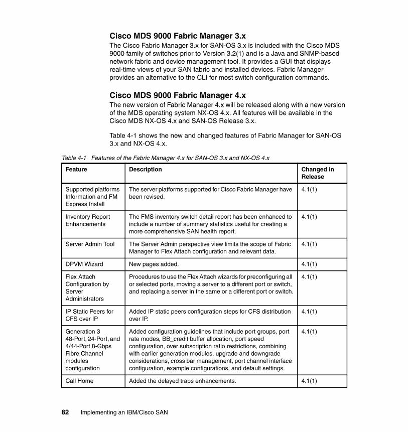
Cisco MDS 9000 Fabric Manager 3.xThe Cisco Fabric Manager 3.x for SAN-OS 3.x is included with the Cisco MDS 9000 family of switches prior to Version 3.2(1) and is a Java and SNMP-based network fabric and device management tool. It provides a GUI that displays real-time views of your SAN fabric and installed devices. Fabric Manager provides an alternative to the CLI for most switch configuration commands.
Cisco MDS 9000 Fabric Manager 4.xThe new version of Fabric Manager 4.x will be released along with a new version of the MDS operating system NX-OS 4.x. All features will be available in the Cisco MDS NX-OS 4.x and SAN-OS Release 3.x.
Table 4-1 shows the new and changed features of Fabric Manager for SAN-OS 3.x and NX-OS 4.x.
Table 4-1 Features of the Fabric Manager 4.x for SAN-OS 3.x and NX-OS 4.x
Feature Description Changed in Release
Supported platforms Information and FM Express Install
The server platforms supported for Cisco Fabric Manager have been revised.
4.1(1)
Inventory Report Enhancements
The FMS inventory switch detail report has been enhanced to include a number of summary statistics useful for creating a more comprehensive SAN health report.
4.1(1)
Server Admin Tool The Server Admin perspective view limits the scope of Fabric Manager to Flex Attach configuration and relevant data.
4.1(1)
DPVM Wizard New pages added. 4.1(1)
Flex Attach Configuration by Server Administrators
Procedures to use the Flex Attach wizards for preconfiguring all or selected ports, moving a server to a different port or switch, and replacing a server in the same or a different port or switch.
4.1(1)
IP Static Peers for CFS over IP
Added IP static peers configuration steps for CFS distribution over IP.
4.1(1)
Generation 3 48-Port, 24-Port, and 4/44-Port 8-Gbps Fibre Channel modules configuration
Added configuration guidelines that include port groups, port rate modes, BB_credit buffer allocation, port speed configuration, over subscription ratio restrictions, combining with earlier generation modules, upgrade and downgrade considerations, cross bar management, port channel interface configuration, example configurations, and default settings.
4.1(1)
Call Home Added the delayed traps enhancements. 4.1(1)
82 Implementing an IBM/Cisco SAN

Cisco Fabric Manager 4.x has been tested with the following software:
� Operating systems
– Windows 2003 SP2, Windows XP SP2, Windows XP SP3, Windows Vista SP1 (Enterprise edition)
– Red Hat Enterprise Linux AS Release 4
– Solaris (SPARC) 8, 9, and 10
– VMWare ESX Server 3.5
� Java
– Sun JRE and JDK 1.5(x) and 1.6(x) is supported
– Java Web Start 1.5 and 1.6
� Browsers
– Internet Explorer 6.x and 7.0
– Firefox 1.5 and 2.0
– Mozilla 1.7 (packaged with Solaris 9)
� Databases
– Oracle Database 10g Express, Oracle Enterprise Edition 10g
– PostgreSQL 8.2 (Windows and Red Hat Enterprise Linux AS Release 4)
– PostgreSQL 8.1 (Solaris 8, 9 and 10)
� Security
– Cisco ACS 3.1 and 4.0
– PIX Firewall
– IP Tables
– SSH v2
– Global Enforce SNMP Privacy Encryption
– HTTPS
Performance Manager
Added the flow creation wizard for performance manager. 4.1(1)
Feature Description Changed in Release
Important: Internet Explorer 7.0 is not supported on Windows 2000 SP4.
Chapter 4. Management tools 83

Minimum hardware requirements for Fabric Manager 4.xFor a PC running Fabric Manager Server on large fabrics (1,000 or more end devices), we recommend using a dual core/dual CPU high-speed system with 2 GB of RAM and 10 GB of free disk space.
FlexAttach functionality in Fabric Manager 4.xThe FlexAttach virtual pWWN feature facilitates server and configuration management. In a SAN environment, the server installation or replacement requires interaction and coordination among the SAN and server administrators. For coordination, it is important that the SAN configuration does not change when a new server is installed or when an existing server is replaced. FlexAttach minimizes the interaction between the server administrator and the SAN administrator by abstracting the real pWWN using virtual pWWNs.
When FlexAttach virtual pWWN is enabled on an interface, a virtual pWWN is assigned to the server interface. The real pWWN is replaced by a virtual pWWN, which is used for a SAN configuration such as zoning.
Server administrators can benefit from FlexAttach in the following ways:
� Preconfigure: Preconfigure SAN for new servers that are not available physically yet. FlexAttach can be enabled on the ports designated for the new servers and use the virtual WWNs assigned for configuring SAN. The new servers are then plugged into the fabric without any change needed in the SAN.
� Replacement to the same port: A failed server can be replaced onto the same port without changing the SAN. The new server gets the same pWWN as the failed server because the virtual pWWN is assigned to the port.
� Replacement to (spare): A spare server, which is on the same NPV device or a different NPV device) can be brought online without changes to the SAN. This action is achieved by moving the virtual port WWN from the current server port to the spare port.
� Server Mobility: A server can be moved to another port on the same NPV device or another NPV device without changing the SAN. This is accomplished by moving the virtual pWWN to the new port. No change is needed if FlexAttach was configured using the physical port WWN of the server to the virtual port WWN mapping.
84 Implementing an IBM/Cisco SAN

We recommend the following when deploying FlexAttach virtual pWWN:
� FlexAttach configuration is supported only on NPV switches.
� Cisco Fabric Services (CFS) IP Version 4 (IPv4) distribution should be enabled.
� Virtual WWNs should be unique across the fabric.
4.1.4 Fabric Manager Server
The Fabric Manager Server component must be started before running Fabric Manager. On a PC machine, the Fabric Manager Server is installed as a service. Fabric Manager Server is responsible for the discovery of the physical and logical fabric, and for listening for SNMP traps, syslog messages, and Performance Manager threshold events.
Install Cisco Fabric Manager Server on a computer on which you want to provide centralized MDS management services and performance monitoring. SNMP operations are used to efficiently collect fabric information. Fabric Manager software, including the server components, requires about 60 MB of hard disk space on your workstation. Fabric Manager Server runs on Windows 2000, Windows 2003, Windows XP, Solaris 8 and 10, and Red Hat Enterprise Linux AS Release 4.
Each computer configured as a Fabric Manager Server can monitor multiple Fibre Channel SAN fabrics. Up to 16 clients (by default) can connect to a single Fabric Manager Server concurrently. The Fabric Manager Clients can also connect directly to an MDS switch in fabrics that are not monitored by a Fabric Manager Server, which ensures that you can manage any of your MDS devices from a single console.
Fabric Manager Server has the following features:
� Multiple fabric management: Fabric Manager Server monitors multiple physical fabrics under the same user interface. This facilitates managing redundant fabrics. A licensed Fabric Manager Server maintains up-to-date discovery information on all configured fabrics so device status and interconnections are immediately available when you open the Fabric Manager Client.
� Continuous health monitoring: MDS health is monitored continuously, so any events that occurred since the last time that you opened the Fabric Manager Client are captured.
� Roaming user profiles: The licensed Fabric Manager Server uses the roaming user profile feature to store your preferences and topology map layouts on the
Chapter 4. Management tools 85
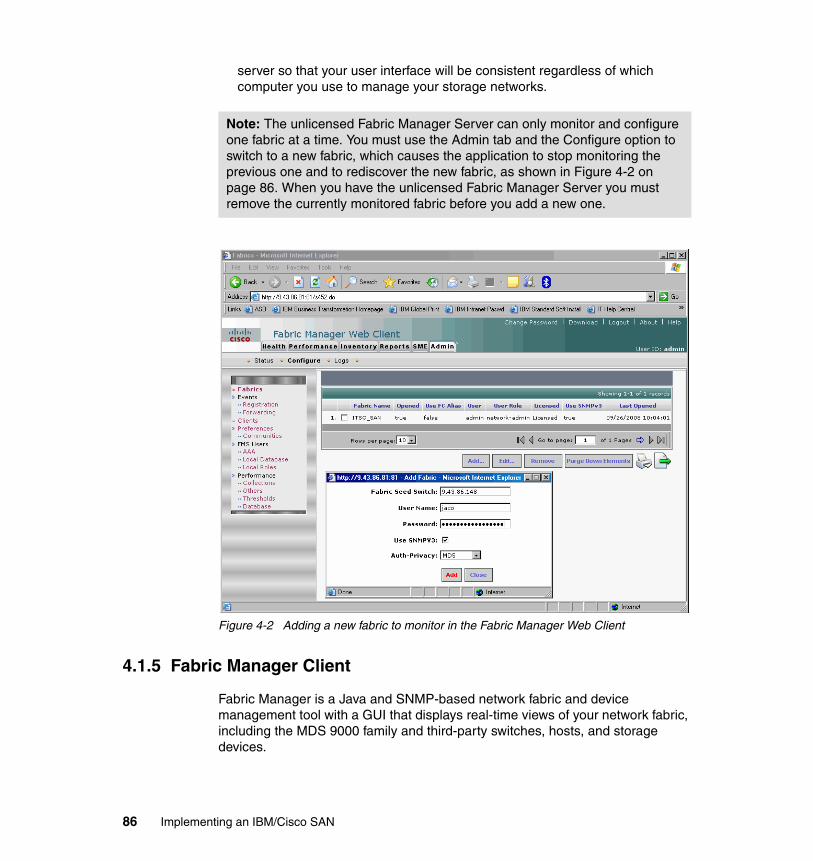
server so that your user interface will be consistent regardless of which computer you use to manage your storage networks.
Figure 4-2 Adding a new fabric to monitor in the Fabric Manager Web Client
4.1.5 Fabric Manager Client
Fabric Manager is a Java and SNMP-based network fabric and device management tool with a GUI that displays real-time views of your network fabric, including the MDS 9000 family and third-party switches, hosts, and storage devices.
Note: The unlicensed Fabric Manager Server can only monitor and configure one fabric at a time. You must use the Admin tab and the Configure option to switch to a new fabric, which causes the application to stop monitoring the previous one and to rediscover the new fabric, as shown in Figure 4-2 on page 86. When you have the unlicensed Fabric Manager Server you must remove the currently monitored fabric before you add a new one.
86 Implementing an IBM/Cisco SAN

In addition, to complete configuration and status monitoring capabilities for the MDS 9000 family of switches, Fabric Manager Client provides Fibre Channel troubleshooting tools. These health and configuration analysis tools use the MDS 9000 switch capabilities including Fibre Channel ping and traceroute.
Fabric Manager Release 4.1(1) and later provides a multi-level security system by adding a server admin role that allows access to limited features. The configuration capabilities of a server admin is limited to FlexAttach and relevant data. FlexAttach is a new feature in Fabric Manager 4.x and has been described in 4.1.3, “System management using the GUI management tools” on page 81.
4.1.6 Fabric Manager Server proxy services
Fabric Manager Client and Device Manager use SNMP to communicate with the Fabric Manager Server. In typical configurations, the Fabric Manager Server may be installed behind a firewall. The SNMP proxy service available in Fabric Manager Release 2.1(1a) or later provides a TCP-based transport proxy for these SNMP requests.
The SNMP proxy service allows you to block all UDP traffic at the firewall and configure Fabric Manager Client to communicate over a configured TCP port. Fabric Manager uses the CLI for managing some features on the switches. These management tasks are used by Fabric Manager and do not use the proxy services. Your firewall must remain open for CLI access for the following:
� External and internal loopback test� Flash files� Create CLI user� Security: ISCSI users� Show image version� Show tech� Switch resident reports (syslog, accounting) � Zone migration � Show cores
If you are using the SNMP proxy service and another application on your server is using port 9198, you must modify your workstation settings.
Chapter 4. Management tools 87

4.1.7 Device Manager
Device Manager presents two views of a single switch:
� The device view displays a graphic representation of the switch configuration and provides access to statistics and configuration information.
� The summary view displays a summary of xE ports (Inter-Switch Links), Fx ports (fabric ports), and Nx ports (attached hosts and storage) on the switch, as well as Fibre Channel and IP neighbor devices.
A summary or detailed statistics can be charted, printed, or saved to a file in tab-delimited format.
4.1.8 Performance Manager
Performance Manager gathers network device statistics historically and provides this information graphically using a Web browser. It presents recent statistics in detail and older statistics in summary. Performance Manager also integrates with external tools such as Cisco Traffic Analyzer.
Performance Manager has three operational stages:
� Definition: The Flow Wizard sets up flows in the switches.
� Collection: The Web Server Performance Collection window collects information about desired fabrics.
� Presentation: Generates Web pages to present the collected data through Fabric Manager Web Server.
Performance Manager can collect statistics for Inter-Switch Links (ISLs), hosts, storage elements, and configured flows. Flows are defined based on a host-to-storage (or storage-to-host) link.
Performance Manager gathers statistics from across the fabric based on collection configuration files. These files determine which SAN elements and SAN links Performance Manager gathers statistics for. Based on this configuration, Performance Manager communicates with the appropriate devices (switches, hosts, or storage elements) and collects the appropriate information at fixed five-minute intervals.
Performance Manager uses a round-robin database to hold the statistical data collected from the fabric. This data is stored based on the configured parameters in the collection configuration file. At each polling interval, Performance Manager gathers the relevant statistics and stores them in the round-robin database. This database is a fixed size and will not grow beyond its preset limits.
88 Implementing an IBM/Cisco SAN
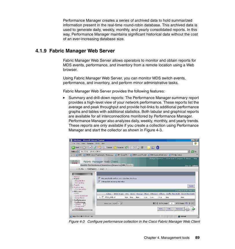
Performance Manager creates a series of archived data to hold summarized information present in the real-time round-robin database. This archived data is used to generate daily, weekly, monthly, and yearly consolidated reports. In this way, Performance Manager maintains significant historical data without the cost of an ever-increasing database size.
4.1.9 Fabric Manager Web Server
Fabric Manager Web Server allows operators to monitor and obtain reports for MDS events, performance, and inventory from a remote location using a Web browser.
Using Fabric Manager Web Server, you can monitor MDS switch events, performance, and inventory, and perform minor administrative tasks.
Fabric Manager Web Server provides the following features:
� Summary and drill-down reports: The Performance Manager summary report provides a high-level view of your network performance. These reports list the average and peak throughput and provide hot-links to additional performance graphs and tables with additional statistics. Both tabular and graphical reports are available for all interconnections monitored by Performance Manager. Performance Manager also analyzes daily, weekly, monthly, and yearly trends. These reports are only available if you create a collection using Performance Manager and start the collector as shown in Figure 4-3.
Figure 4-3 Configure performance collection in the Cisco Fabric Manager Web Client
Chapter 4. Management tools 89
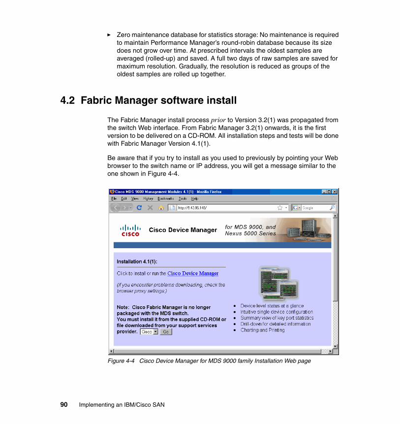
� Zero maintenance database for statistics storage: No maintenance is required to maintain Performance Manager’s round-robin database because its size does not grow over time. At prescribed intervals the oldest samples are averaged (rolled-up) and saved. A full two days of raw samples are saved for maximum resolution. Gradually, the resolution is reduced as groups of the oldest samples are rolled up together.
4.2 Fabric Manager software install
The Fabric Manager install process prior to Version 3.2(1) was propagated from the switch Web interface. From Fabric Manager 3.2(1) onwards, it is the first version to be delivered on a CD-ROM. All installation steps and tests will be done with Fabric Manager Version 4.1(1).
Be aware that if you try to install as you used to previously by pointing your Web browser to the switch name or IP address, you will get a message similar to the one shown in Figure 4-4.
Figure 4-4 Cisco Device Manager for MDS 9000 family Installation Web page
90 Implementing an IBM/Cisco SAN

Fabric Manager Software for Windows launches if autorun is enabled when the CD is placed in the CD-ROM drive. Alternatively, you can point your browser to install _windows.htm to access the documentation and install the software from the CD-ROM.
Once we load the CD-ROM, we see the initial MDS 9000 family Product CD-ROM Web page, as shown in Figure 4-5.
Figure 4-5 Install Management Software
Note: The contents of the CD-ROM were copied to the server’s internal disk in our example. Also, the CD-ROM is a source of documentation, and it contains other tools such as Java, PostgreSQL, and Ethereal.
Chapter 4. Management tools 91

To install:
1. When presented with the Cisco Fabric Manager Software install front page, we select to go directly to the Fabric Manager installation page, as shown in Figure 4-6.
Figure 4-6 Install Management Software drop-down menu
Note: We recommend that you install the latest version of Fabric Manager applications. Fabric Manager is backward-compatible with the Cisco MDS SAN-OS and NX-OS. Upgrade Fabric Manager software first and then upgrade the Cisco MDS SAN-OS or NX-OS.
92 Implementing an IBM/Cisco SAN

2. Select Installing Fabric Manager, as this is the first install, as shown in Figure 4-7.
Figure 4-7 Fabric Manager Software options
Note: Before upgrading or uninstalling Fabric Manager or Device Manager, make sure that any instances of these applications have been shut down.
Note: Fabric Manager requires Java 1.5 or 1.6, and the CD-ROM contains the installation binary if necessary.
Chapter 4. Management tools 93

3. Next select Fabric Manager Installer, as shown in Figure 4-8.
Figure 4-8 Installing Fabric Manager
94 Implementing an IBM/Cisco SAN
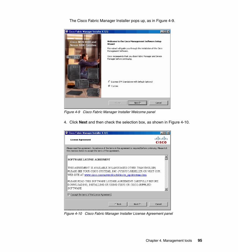
The Cisco Fabric Manager Installer pops up, as in Figure 4-9.
Figure 4-9 Cisco Fabric Manager Installer Welcome panel
4. Click Next and then check the selection box, as shown in Figure 4-10.
Figure 4-10 Cisco Fabric Manager Installer License Agreement panel
Chapter 4. Management tools 95

There are two types of installation:
� Fabric Manager Server � Fabric Manager Standalone
Fabric Manager Standalone is a single application containing Fabric Manager Client and a local version of Fabric Manager Server bundled together. Fabric Manager Standalone allows you to discover and monitor the immediate fabric. Fabric Manager Server has the same functionality, but, as described in 4.1.4, “Fabric Manager Server” on page 85, it allows you to connect by default up to 16 users concurrently.
Additionally, it allows the Fabric Manager Web Server to access a number of configuration and monitoring options using a Web browser. The Fabric Manager Web Server functionality is discussed later in this chapter. To continue the installation choose Fabric Manager Standalone and select Next (Figure 4-11).
Figure 4-11 Cisco Fabric Manager Installer Install Options panel
96 Implementing an IBM/Cisco SAN

Fabric Manager requires a database. If you have an Oracle database, you can use it by providing the connection information. If you do not have an Oracle database, or you prefer a GNU licensed database, the MDS 9000 family Product CD-ROM includes PostgreSQL (Figure 4-12). To install PostgreSQL check PostgreSQL, fill in the database password field, and click Next.
Figure 4-12 Cisco Fabric Manager Installer Database Options panel
Note: You can use an existing Postgres installation, but before installing FM you must create a database with the name dcmd, and define a user and a password. After that you must choose an existing database option in the FM installation panel and specify a database URL, DB user name, and password, as shown in Figure 4-12 on page 97.
Chapter 4. Management tools 97

We enter a password for Fabric Manager (Figure 4-13) and select Next.
Figure 4-13 Cisco Fabric Manager Installer User Options panel
Next we must choose the authentication and authorization mode. All MDS 9000 family switches can perform local authentication or authorization using the local database stored on the MDS 9000 family switch, director, management workstation, or remote authentication or authorization using AAA servers. The authentication, authorization, and accounting (AAA) feature verifies the identity of, grants access to, and tracks the actions of users managing a switch.
98 Implementing an IBM/Cisco SAN

We choose Local as the authentication and authorization mode. This means that all user accounts and authentication credentials are stored locally on a management workstation where we are going to install the Fabric Manager software. The other authentication options that you can choose are Radius, TACACS, and MDS, as shown in Figure 4-14.
Figure 4-14 Cisco Fabric Manager Installer Authentication Options panel
Note: When the MDS radio button is selected, the FM authentication uses the user database in the switch for authentication.
Chapter 4. Management tools 99

Figure 4-15 shows two possible configuration options:
� FC Alias � SNMPv3 against SNMPv2
We choose FC Aliases as the fabric default to simplify fabric management using aliases instead of WWN addresses. We can choose to use only SNMPv3 and disable SNMPv2 for security reasons if required.
Figure 4-15 Cisco Fabric Manager Installer Configuration Options panel
100 Implementing an IBM/Cisco SAN

The install process starts. In our case it ran for approximately five minutes. To follow what is happening use the log window (Figure 4-16).
Figure 4-16 Cisco Fabric Manager Installer installing panel
At the end of the installation process we can elect to have Fabric Manager create desktop icons and launch Fabric Manager or Desktop Manager, as shown in Figure 4-17. We select only to create icons and click Finish.
Figure 4-17 Cisco Fabric Manager Installer Installation completed successfully panel
Chapter 4. Management tools 101

4.2.1 Launching Fabric Manager
You can start Fabric Manager from the icon on your desktop or the Windows Start menu. Enter the IP address or host name of your switch, the user name and password, and click Discover, as shown in Figure 4-18.
Figure 4-18 FM Discover New Fabric
If you have more than one fabric to manage, repeat the above process until you have all your fabrics discovered. Select which fabric you want to manage and click Open (Figure 4-19).
Figure 4-19 Fabric Manager Control Panel
102 Implementing an IBM/Cisco SAN

When starting Fabric Manager, you will see the logical view of your fabric, as shown in Figure 4-20.
Figure 4-20 Fabric logical view
The Fabric Manager window shows a graphical presentation of our switch fabric on the bottom right, an information area on the top, and a navigation window on the left, which is divided into a logical menu at the top and a physical menu at the bottom. The content of the information area changes accordingly to represent the selection chosen in the navigation menu, showing the current selection at the top.
SNMP time outsFabric Manager uses the SNMP protocol to communicate with the switch. SNMP is a stateless protocol, and when you apply changes to the switch, Fabric Manager sends a request packet with the changes to the switch and waits for a response packet.
Depending on your network, either the request packet or the response packet might end up being dropped. This results in a SNMP time-out message. If you
Chapter 4. Management tools 103

get this message, you do not know which of the packets was dropped. This means that you do not know whether your changes are applied to the switch. We recommend that you click Refresh Values, as shown in Figure 4-21, to ensure that the information in Fabric Manager is up to date before making any further changes.
Figure 4-21 Refresh displayed values
Stopping Fabric ManagerIf you made changes to the running configuration that have not yet been copied to the startup configuration, you get a message similar to that shown in Figure 4-22 when you exit from a Fabric Manager session.
Figure 4-22 Save changes
Click Yes to save changes to the copy configuration table. After the copy process is finished you can close Fabric Manager.
104 Implementing an IBM/Cisco SAN

4.2.2 Launching Device ManagerTo launch or install Device Manager, you can use a Web browser. Provide the IP address of the switch that you want to manage. When you click Device Manager, as shown in Figure 4-23, Device Manager will be run or installed.
Figure 4-23 Launching or running the Cisco Device Manager
Chapter 4. Management tools 105

When starting Device Manager, we are prompted for authentication to log in to the switch. Use the same user name and password as for Fabric Manager as shown in Figure 4-24.
Figure 4-24 Device Manager Login
Upon successful login, the Device Manager application is started and we are presented with a graphical representation of the physical switch, as shown in Figure 4-25.
Figure 4-25 Device Manager
106 Implementing an IBM/Cisco SAN

The Device Manager window shows a graphical presentation of the switch while displaying the power, fan trays, switch modules, and respective ports installed.
Figure 4-26 shows the Device Manager port summary window. It shows port mode for all ports and the WWNs of connected devices. There are statistics for transmission, errors, and discards. Above the list are current CPU, memory, and flash utilization information and thresholds. This view can be filtered for any particular VSAN.
Figure 4-26 Device Manager summary
Chapter 4. Management tools 107

4.2.3 Launching the Fabric Manager Web Server Client
To launch the Fabric Manager Web Client, use a Web browser and point to the IP address of the Fabric Manager Web Server (FMS) and a port number, as shown in Figure 4-27.
Figure 4-27 Fabric Manager Web Server Login window
Another way to display the licenses is to use the CLI. In Example 4-3 we use the CLI to display the licenses that are installed on the switch.
Example 4-3 Fabric Manager Server lIcense installed on the MDS switch
mds9222i-1# show license usageFeature Ins Lic Status Expiry Date Comments Count-------------------------------------------------------------------------------DMM_184_PKG No 0 Unused Grace 120D 0HDMM_9222i_PKG No 0 Unused Grace 120D 0H
Note: To be able to use the Performance Manager, you must acquire and install the Cisco Fabric Manager Server Package (FMSERVER_PKG), if not already present on the switch. The Fabric Manager Server Package License installed on the MDS 9222i is shown in Example 4-3 on page 108.
108 Implementing an IBM/Cisco SAN

FM_SERVER_PKG Yes - In use never -MAINFRAME_PKG Yes - Unused never -ENTERPRISE_PKG Yes - Unused never -DMM_FOR_SSM_PKG No 0 Unused Grace 120D 0HSAN_EXTN_OVER_IP Yes 1 Unused never -SME_FOR_9222I_PKG Yes - Unused never -PORT_ACTIVATION_PKG No 0 Unused -SME_FOR_IPS_184_PKG No 0 Unused Grace 120D 0HSTORAGE_SERVICES_184 No 0 Unused Grace 120D 0HSAN_EXTN_OVER_IP_18_4 Yes 1 Unused never -SAN_EXTN_OVER_IP_IPS2 No 0 Unused Grace 120D 0HSAN_EXTN_OVER_IP_IPS4 No 0 Unused Grace 120D 0HSTORAGE_SERVICES_9222i No 0 Unused Grace 120D 0HSTORAGE_SERVICES_SSN16 No 0 Unused Grace 120D 0H10G_PORT_ACTIVATION_PKG No 0 Unused -STORAGE_SERVICES_ENABLER_PKG Yes 1 Unused never --------------------------------------------------------------------------------
Fabric Manager Web Server can be used to gather inventory information regarding monitored SANs. The Inventory tab shows an inventory of the selected SAN, fabric, or switch. You can export this information to an ASCII file in comma-separated value (CSV) format that can be read by applications such as Microsoft® Excel®. You can set the number of rows and columns per page.
The Inventory tab contains the following subtabs:
� VSANs: Shows details about VSANs
� Switches: Shows details about switches
� Licenses: Shows details about the licenses in use in the fabric
� Modules: Shows details for MDS switching and services modules, fans, and power supplies
� End Devices: Shows the host and storage ports
� ISLs: Shows the Inter-Switch Links
� NPV Links: Shows the links between NPV devices and ports
� Zones: Shows the active zone members (including those in inter-VSAN zones)
� Summary: Shows VSANs, switches, ISLs, ports, and end devices
Chapter 4. Management tools 109

To view the inventory summary regarding SAN switches in our fabrics use the Inventory tab, as shown in Figure 4-28.
Figure 4-28 Inventory Summary tab in the CISCO Fabric Manager Web Client
110 Implementing an IBM/Cisco SAN

To view inventory information regarding VSANs click the VSANs tab in the Inventory section, as shown in Figure 4-29.
Figure 4-29 VSAN’s Inventory tab in the Cisco Fabric Manager Web Server
To view inventory information regarding FC switches in a particular fabric click the Switches tab in the Inventory section, as shown in Figure 4-30.
Figure 4-30 Switches Inventory tab in the Cisco Fabric Manager Web Client
Chapter 4. Management tools 111

To view inventory information regarding licenses installed on switches click the License tab in the Inventory section, as shown in Figure 4-31.
Figure 4-31 License Inventory tab in the Cisco Fabric Manager Web Client
To view inventory information regarding line cards and modules in a particular switch click the Modules tab in the Inventory section, as shown in Figure 4-32.
Figure 4-32 Modules Inventory tab in the Cisco Fabric Manager Web Client
112 Implementing an IBM/Cisco SAN

To view inventory information regarding end devices in our SAN click the End Devices tab in the Inventory section, as shown in Figure 4-33.
Figure 4-33 End Devices inventory tab in the Cisco Fabric Manager Web Client
To view inventory information regarding ISLs in our SAN click the ISLs tab in the the Inventory section, as shown in Figure 4-34.
Figure 4-34 ISLs inventory tab in the Cisco Fabric Manager Web Client
Chapter 4. Management tools 113

To view inventory information regarding zones in our SAN click the Zones tab in the Inventory section, as shown in Figure 4-35.
Figure 4-35 Zones inventory tab in the Cisco Fabric Manager Web Client
The Fabric Manager Web Server allows you to create customized reports based on historical performance, events, and inventory information gathered by the Fabric Manager Server. You can create aggregate reports with summary and detailed views. You can also view previously saved reports.
The Report tab contains the following subtabs:
� View: Displays previously saved reports
� Generate: Generates a custom report based on the selected report template
� Edit: Edits an existing report template
� Create: Creates a report template, allowing you to select any combination of events, performance categories, and inventory
� Scheduled Jobs: Displays scheduled jobs based on the selected report template
You can create custom reports from all or any subset of information gathered by Fabric Manager Server. You create a report template by selecting events, performance, and inventory statistics that you want in your report and set the desired SAN, fabric, or VSAN to limit the scope of the template.
You can generate and schedule a report of your fabric based on this template immediately or at a later time. Fabric Manager Web Server saves each report based on the report template used and the time at which you generate the report.
114 Implementing an IBM/Cisco SAN

To create a custom report in Fabric Manager Web Client:
1. Click the Reports tab, then the Create button, as shown in Figure 4-36.
Figure 4-36 Create a customer report in the Cisco Fabric Manager Web Client
2. Choose the Generate button and get the report from the SAN network, as shown in Figure 4-37 and Figure 4-38 on page 116.
Figure 4-37 Generate the report from the SAN in the Cisco Fabric Manager Web Client
Chapter 4. Management tools 115

Figure 4-38 A part of the SAN report generated in the Cisco Fabric Manager Web Client
116 Implementing an IBM/Cisco SAN

If you choose to attach to the SAN report a Visio® drawing of the SAN network you can download the Visio file and get a detailed graphical view of your SAN, as shown in Figure 4-39. A link to the Visio drawing is found at the top the report.
Figure 4-39 Visio Drawing of the SAN network created by the reporting tool
You can use the Fabric Manager Web Client to collect and analyze performance data from a monitored SAN. Before doing that it is necessary to configure a performance monitoring environment.
Chapter 4. Management tools 117

As shown in Figure 4-40, select Configure under the Admin tab to configure a fabric performance data collection.
Figure 4-40 Configure Fabric Manager to collect performance data
Note: If you are managing your fabrics with Performance Manager, you need to set up an initial set of flows and collections on the fabric. You can use the Fabric Manager Web server to add and remove performance collections. See Creating Performance Collections under the Help panel.
118 Implementing an IBM/Cisco SAN

If you are managing your fabrics with Performance Manager, you need to set up an initial set of flows and collections on the fabric. You can use Fabric Manager Web Server to add and remove performance collections. In order to configure performance collections click the Admin tab, choose Configure, and from the menu on the left choose Collections, as shown in Figure 4-41. You will get the Edit Collection window to set up the required parameters, as shown in Figure 4-42.
Figure 4-41 Configure performance collections
Figure 4-42 Edit collection parameters
Chapter 4. Management tools 119
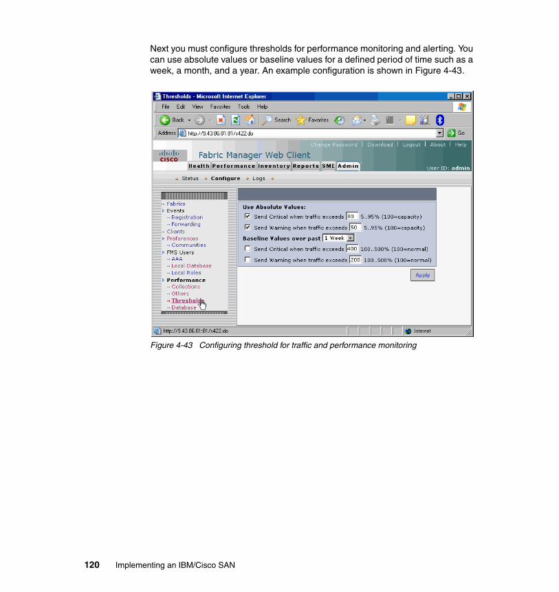
Next you must configure thresholds for performance monitoring and alerting. You can use absolute values or baseline values for a defined period of time such as a week, a month, and a year. An example configuration is shown in Figure 4-43.
Figure 4-43 Configuring threshold for traffic and performance monitoring
120 Implementing an IBM/Cisco SAN

When all performance parameters are set you can start to collect performance data regarding traffic in your monitored fabrics. As a presentation you can use graphical or spreadsheet reports, as shown respectively in Figure 4-44 and in Figure 4-45 on page 122.
Figure 4-44 Graphical performance reports from the Cisco Fabric Manager Web Client
Note: Performance data is available for display once data collection has progressed for a time period.
Chapter 4. Management tools 121

Figure 4-45 Spreadsheet performance reports from Cisco Fabric Manager Web Client
122 Implementing an IBM/Cisco SAN

Additionally, you can collect performance reports for specific components or characteristics of your SAN networks such as:
� End devices (Figure 4-46)� ISLs (Figure 4-47 on page 124)� NPV links� Flows� Ethernet (FCIP and iSCSI) (Figure 4-48 on page 124)� CPU and memory utilization (Figure 4-49 on page 125)� Traffic Analyzer reports� Traffic predictions (Figure 4-50 on page 125)� Switch bandwidth (Figure 4-51 on page 126)
Figure 4-46 Performance report for end devices
Chapter 4. Management tools 123

Figure 4-47 Performance report for ISLs
Figure 4-48 Performance report for FCIP and iSCSI connections
124 Implementing an IBM/Cisco SAN

Figure 4-49 Performance report for CPU and memory utilization
Figure 4-50 Traffic prediction for ISLs in a one week period of time
Chapter 4. Management tools 125

Figure 4-51 Switch bandwidth report
You can use the Fabric Manager Web Client to gather and present data regarding the health status of monitored SAN networks. There are a few options available to gather valuable information regarding your SAN:
� Summary report: Shows a summary of events and problems for all SANs, or a selected SAN, fabric, or switch. You can click any blue link for more information about that item.
� Fabric Events: Shows a detailed list of events and hardware, or accounting. You can filter these events by severity, date, and type of event.
� SysLog: Shows a detailed list of system messages. You can filter these events by severity, date, and type of event.
� Analysis: Enables you to schedule or run analysis reports and compile results to analyze the Fabric Manager Server database statistics.
126 Implementing an IBM/Cisco SAN

Examples of reports are shown in Figure 4-52, Figure 4-53 on page 128 and Figure 4-54 on page 129.
Figure 4-52 Overall summary SAN Health report
Chapter 4. Management tools 127

Figure 4-53 Fabric Events for all VSANs
128 Implementing an IBM/Cisco SAN

Figure 4-54 Analysis of the Storage to Host Connectivity
4.2.4 Obtaining the latest source filesDirectors and switches in the Cisco MDS 9000 Multilayer Fabric Switch Family are shipped with the current levels of firmware already installed at the time of shipping. This code level is usually sufficient to begin the switch implementation process, but we recommend that you regularly check for the latest supported code levels and install updated code when required.
Note: We strongly recommend checking new firmware compatibility with all devices and vendors connected to the SAN.
Chapter 4. Management tools 129

Attention: Cisco regularly makes new code releases available on their Web site for authorized users to download. IBM conducts additional integration testing on this code before issuing its approval, so we recommend that you always install only the IBM recommended code levels.
If you experience problems with an unapproved code release, IBM might ask you to install an approved release before continuing with problem resolution.
130 Implementing an IBM/Cisco SAN

Chapter 5. Security
Before the existence of storage area networks (SANs), and during the initial migration to SANs, the storage environment was fairly secure due to its physical isolation from the remainder of the communication network. SANs were typically entirely contained in the data center, and there are explicit procedural and physical controls to control access to the data center. However, with the advent of optical and FCIP solutions designed to improve high availability and disaster recovery this is no longer the case. SANs that span outside a single data center are now commonplace.
The concepts of who will manage the SAN and how will they manage the SAN are also areas that need to be considered. Effective security management strategies can only be implemented once these procedural questions have been discussed and finalized.
A complete discussion of all the advanced security functions available in the MDS 9000 Multilayer Fabric Switch family is beyond the scope of this book. The purpose of this chapter is to provide a high-level overview of the security features that are available. We discuss security from two different perspectives:
� Securing management access to the MDS switch itself � Securing the Fibre Channel fabric
5
© Copyright IBM Corp. 2009. All rights reserved. 131

5.1 Securing management access to the switchTypically, both CLI and SNMP are used to manage the switch. As such, they both need to be addressed with regards to security. The following security features are available on the MDS 9000 Multilayer Fabric Switch family in order to secure management access to the MDS switch:
� SSH service is available.
� SNMPv1, SNMPv2c, and SNMPv3 are all available.
� IP Access Control Lists.
� Role-based authorization.
� Authentication, Authorization, Accounting (AAA) with Terminal Access Controller Access Control System Plus (TACACS+) and Remote Access Dial-In User Services (RADIUS).
� The Federal Information Processing Standards (FIPS).
5.1.1 SSH serviceEach switch in the MDS 9000 Multilayer Fabric Switch family supports the Secure Shell (SSH) facility. SSH provides several benefits over traditional management facilities such at Telnet, FTP, and TFTP, among which are strong authentication and encryption. SSH can be enabled on each switch to ensure secure access using the CLI, providing encrypted user authentication and data exchange.
The SSH Client in the MDS also supports a secured method when copying files (configuration files, log files, SAN-OS and NX-OS images) to and from the switch.
SSH provides secure communications to the Cisco SAN-OS and NX-OS CLI. You can use SSH keys for the following SSH options:
� SSH1� SSH2, using RSA� SSH2, using DSA
Be sure to have an SSH server key pair with the appropriate version before enabling the SSH service. Generate the SSH server key pair according to the SSH client version used. The number of bits specified for each key pair ranges from 768 to 2048.
132 Implementing an IBM/Cisco SAN

The SSH service accepts three types of key pairs for use by SSH versions 1 and 2:
� The rsa1 option generates the RSA1 key pair for the SSH Version 1 protocol.� The dsa option generates the DSA key pair for the SSH Version 2 protocol.� The rsa option generates the RSA key pair for the SSH Version 2 protocol.
In order to check or modify the SSH configuration go to the Physical Attributes section in Fabric Manager and select Switches → Security → SSH and Telnet, as shown in Figure 5-1.
Figure 5-1 SSH keys configuration in Fabric Manager
Note: If you delete all of the SSH keys, you cannot start a new SSH session.
Chapter 5. Security 133

Select the create row icon to generate the SSH server key pair, as shown in Figure 5-2.
Figure 5-2 Create new SSH keys pair in Fabric Manager
In the Create SSH Key dialog box select the MDS switches, define the SSH protocol, and specify the number of bits used to generate the key pairs in the NumBits drop-down menu, as shown in Figure 5-3.
Figure 5-3 Define SSH keys pair configuration
Note: We strongly recommend using SSH instead of Telnet to manage MDS 9000 family switches.
To transfer files to and from MDS 9000 family switches we recommend using SCP (secure copy) and SFTP (secure FTP) instead of FTP or TFTP.
134 Implementing an IBM/Cisco SAN

5.1.2 SNMP securityThe MDS switch supports SNMPv1, SNMPv2c, and SNMPv3 (encrypted) for SNMP access to the switch. SNMPv1 and SNMPv2c use the concept of a community string to authorize read and write access to the switch. SNMPv3 requires that a user ID/password be entered in order to access the switch, as shown in Figure 5-4.
Figure 5-4 SNMP security
The CLI and SNMP user ID and password are maintained separately, so it is possible for the same ID to have a different password for both the SNMP and the CLI. However, we do not recommend this.
SNMPv3 is an interoperable standards-based protocol for network management. SNMPv3 provides secure access to devices by a combination of authenticating and encrypting frames over the network. The security features provided in SNMPv3 are:
� Message integrity: Ensures that a packet has not been tampered with in-transit
� Authentication: Determines whether the message is from a valid source
� Encryption: Scrambles the packet content to prevent it from being seen by unauthorized sources
SNMPv3 provides for both security models and security levels. A security model is an authentication strategy that is set up for a user and the role in which the user resides. A security level is the permitted level of security within a security model. A combination of a security model and a security level determines which security mechanism is employed when handling an SNMP packet.
Chapter 5. Security 135

The Cisco SAN-OS and NX-OS software implement RFC 3414 and RFC 3415, including user-based security model (USM) and role-based access control. While SNMP and the CLI have common role management and share the same credentials and access privileges, the local user database was not synchronized in earlier releases. SNMPv3 user management can be centralized at the AAA server level. This centralized user management allows the SNMP agent running on the Cisco MDS switch to leverage the user authentication service of the AAA server. Once user authentication is verified, the SNMP PDUs are processed further. Additionally, the AAA server is also used to store user group names. SNMP uses the group names to apply the access/role policy that is locally available in the switch.
Any configuration changes made to the user group, role, or password results in database synchronization for both SNMP and AAA.
Users are synchronized as follows:
� Deleting a user using either command results in the user being deleted for both SNMP and the CLI.
� User-role mapping changes are synchronized in SNMP and the CLI.
� Existing SNMP users continue to retain the auth and priv passphrases without any changes.
� If the management station creates an SNMP user in the usmUserTable, the corresponding CLI user is created without any password (login is disabled) and will have the network-operator role.
5.1.3 IP Access Control ListsThe MDS 9000 Multilayer Switch family can route IP Version 4 (IPv4) traffic between Ethernet and Fibre Channel interfaces. The IP static routing feature routes traffic between VSANs. To do so, each VSAN must be in a different IPv4 subnetwork. Each MDS 9000 Multilayer Switch family provides the following services for network management systems:
� IP forwarding on the out-of-band Ethernet interface on the front panel of the supervisor modules.
� IP forwarding on the in-band Fibre Channel interface using the IP over Fibre Channel (IPFC) function: IPFC specifies how IP frames can be transported over Fibre Channel frames so network management systems information can cross the Fibre Channel network without using an overlay Ethernet network.
� IP routing (default routing and static routing): If your configuration does not need an external router, you can configure a default route using static routing.
136 Implementing an IBM/Cisco SAN

In the MDS 9000 Multilayer Switch family, IP Access Control Lists (ACLs) provide a basic mechanism to secure the Ethernet management interface and in-band management via IP over Fibre Channel (IPFC). Therefore, these ACLs can only be applied to either the management interface or logical VSAN interfaces.
IPv4 Access Control Lists (IPv4-ACLs and IPv6-ACLs) provide basic network security to all switches in the MDS 9000 Multilayer Switch family. IPv4-ACLs and IPv6-ACLs restrict IP-related traffic based in the configured IP filters. A filter contains the rules to match an IP packet, and if the packet matches, the rule also stipulates whether the packet should be permitted or denied.
Each switch in the MDS 9000 Multilayer Switch family can have a maximum of 128 IPv4-ACLs or 128 IPv6-ACLs, and each IPv4-ACL or IPv6-ACL can have a maximum of 256 filters.
An ACL is a sequential collection of permit and deny conditions that apply to IP addresses. The MDS SAN-OS software tests addresses against the conditions in an access list one by one. The first match determines whether the software accepts or rejects the address. Because the software stops testing conditions after the first match, the order of the conditions is critical. If no conditions match, the software rejects the address.
An IP protocol can be configured using an integer ranging from 0 to 255 to represent a particular IP protocol. Alternatively, you can specify the name of a protocol (iCMP, IP, TCP, OR UDP). IP includes Transmission Control Protocol (TCP), User Datagram Protocol (UDP), Internet Control Message Protocol (ICMP), and other protocols.
The source/source-wildcard and destination/destination-wildcard are specified in one of two ways:
� Using the 32-bit quantity in four-part, dotted decimal format (10.1.1.2/0.0.0.0 is the same as host 10.1.1.2.)
� Using the any option as an abbreviation for a source/source-wildcard or destination/destination-wildcard (0.0.0.0/255.255.255.255)
Crypto IPv4-ACLsIP access control lists (IPv4-ACLs) provide basic network security to all switches in the Cisco MDS 9000 family. IPv4 IP-ACLs restrict IP-related traffic based on the configured IP filters.
In the context of crypto maps, IPv4-ACLs are different from regular IPv4-ACLs. Regular IPv4-ACLs determine what traffic to forward or block at an interface. For example, IPv4-ACLs can be created to protect all IP traffic between subnet A and subnet Y or Telnet traffic between host A and host B.
Chapter 5. Security 137

Crypto IPv4-ACLs are used to define which IP traffic requires crypto protection and which traffic does not.
Crypto IPv4-ACLs associated with IPsec crypto map entries have four primary functions:
� Select outbound traffic to be protected by IPsec (permit = protect).
� Indicate the data flow to be protected by the new SAs (specified by a single permit entry) when initiating negotiations for IPsec SAs.
� Process inbound traffic to filter out and discard traffic that should have been protected by IPsec.
� Determine whether to accept requests for IPsec SAs on behalf of the requested data flows when processing IKE negotiation from the IPsec peer.
5.1.4 Role-based authorizationAll management access within the MDS 9000 Multilayer Switch family is based on roles. Role-based authorization limits access to switch operations by assigning users to roles. Users are restricted to performing the management operations that are explicitly permitted based on the roles to which they belong.
Note: If you want some traffic to receive one type of IPsec protection (for example, encryption only) and other traffic to receive a different type of IPsec protection (for example, both authentication and encryption), create two IPv4-ACLs. Use both IPv4-ACLs in different crypto maps to specify different IPsec policies.
Note: Each role can contain multiple users, and each user can be part of multiple roles. For example, if role 1 users are only allowed access to configuration commands, and role 2 users are only allowed access to debug commands, then if user belongs to both role 1 and role 2, he can access configuration as well as debug commands.
138 Implementing an IBM/Cisco SAN

By default, these roles exist in all switches:
� Network operator (network-operator)
Has permission to view the configuration only. The operator cannot make any configuration changes.
� Network administrator (network-admin)
Has permission to execute all commands and make configuration changes. The administrator can also create and customize up to an additional 64 roles.
� Default-role
Has permission to use the GUI (Fabric Manager and Device Manager). This access is automatically granted to all users in order for them to use the GUI.
These default roles cannot be changed or deleted.
You can use SNMP to modify a role that was created using CLI and vice versa. Each role in SNMP is the same as a role created or modified through the CLI. Common roles allow you to use a set of rules to set the scope of VSAN security. Each role can be restricted to one or more VSANs as required.
Note: If a user only belongs to one of the newly created roles and that role is subsequently deleted, then the user immediately defaults to the network-operator role.
Note: If you belong to multiple roles, you can execute a union of all the commands permitted by these roles. Access to a command takes priority over being denied access to a command. For example, suppose that you belong to a group called STG and you were denied access to configuration commands. However, you also belong to the ITSO group and are permitted access to configuration commands. In this case, you will have access to configuration commands.
Chapter 5. Security 139

If you need to configure roles using the GUI, expand Switches → Security and then select Users and Roles from the Physical Attribute pane. Click the Roles tab in the Information pane, as shown in Figure 5-5.
Figure 5-5 Configuring Users and Roles in Fabric Manager
You can add a new role by selecting the create row icon in Fabric Manager, as shown in Figure 5-6.
Figure 5-6 Add new Role in Fabric Manager
140 Implementing an IBM/Cisco SAN

At the next step you must provide information regarding new role configuration, as shown in Figure 5-7, and click Create.
Figure 5-7 Define a new role in Fabric Manager
Role configuration tasks can also be done from the CLI, as shown in Example 5-1.
Example 5-1 Create and verify roles in CLI
mds9222i-1# configure terminalmds9222i-1(config)# role name SAN_monitords9222i-1(config-role)# description SAN Monitoringmds9222i-1(config-role)# vsan policy denymds9222i-1(config-role-vsan)# permit vsan 10mds9222i-1(config-role-vsan)# permit vsan 20mds9222i-1(config-role-vsan)# permit vsan 30mds9222i-1(config-role-vsan)# exitmds9222i-1(config-role)# rulemds9222i-1(config-role)# rule 1 permit show feature systemmds9222i-1(config-role)# rule 2 permit show feature modulemds9222i-1(config-role)# rule 3 permit show feature hardwaremds9222i-1(config-role)# rule 4 permit show feature environmentmds9222i-1(config-role)# rule 5 permit show feature snmpmds9222i-1(config-role)# rule 6 deny execmds9222i-1(config-role)# endmds9222i-1# show roleRole: network-adminDescription: Predefined Network Admin group. This role cannot be modifiedAccess to all the switch commands
Chapter 5. Security 141

Role: network-operatorDescription: Predefined Network Operator group. This role cannot be modifiedAccess to Show commands and selected Exec commands
Role: server-admin Description: Predefined system role for server administrators. This role cannot be modified. Vsan policy: permit (default) ------------------------------------------------- Rule Type Command-type Feature ------------------------------------------------- 1 permit show * 2 permit exec install
Role: default-role Description: This is a system defined role and applies to all users. Vsan policy: permit (default) ------------------------------------------------- Rule Type Command-type Feature ------------------------------------------------- 1 permit show system 2 permit show snmp 3 permit show module 4 permit show hardware 5 permit show environment
Role: ITSO_Admins Description: Admins from ITSO in San Jose Vsan policy: deny Permitted vsans: 1-4093 ------------------------------------------------- Rule Type Command-type Feature ------------------------------------------------- 1 permit show * 2 permit config * 3 permit exec *
Role: SAN_monitor Description: SAN Monitoring Vsan policy: deny Permitted vsans: 10,20,30 ------------------------------------------------- Rule Type Command-type Feature ------------------------------------------------- 1 permit show system 2 permit show module 3 permit show hardware 4 permit show environment
142 Implementing an IBM/Cisco SAN

5 permit show snmp 6 deny exec *
5.1.5 AAA using RADIUS and TACACS+The authentication, authorization, and accounting (AAA) mechanism verifies the identify of, grants access to, and tracks the actions of users managing a switch. Authentication is the process of verifying one’s identity. The verification is based on the user ID and password entered by the person logging into the switch. On the MDS switch you can either use local authentication or remote authentication using TACACS+ or RADIUS to communicate with AAA servers. Figure 5-11 on page 148 shows a flow chart of the process.
Along with the authentication process is an authorization process, where your management capabilities are determined based upon the access given when your user ID was created. Access rights can be determined by role as well as VSAN.
Accounting refers to the log that is kept for tracking each management session in a switch. This log provides accountability and can be an invaluable tool for troubleshooting.
RADIUS is a distributed client-server system that secures networks against unauthorized access. RADIUS clients run on MDS switches and sends authentication requests to a central RADIUS server that contains all user authentication and network service access information.
RADIUS is a fully open protocol, distributed in source code format, that can be modified to work with any security system currently available on the market.
You can set the RADIUS server address, the RADIUS preshared key, the RADIUS server time-out interval, and iterations of the RADIUS server; define vendor-specific attributes; and display RADIUS server details.
You must configure the RADIUS preshared key to authenticate the switch to the RADIUS server. The length of the key is restricted to 64 characters and can include any printable ASCII characters (white spaces are not allowed). You can configure a global key to be used for all RADIUS server configurations on the switch. You can override this global key assignment by explicitly using the key option when configuring an individual RADIUS server.
Chapter 5. Security 143

To configure a RADIUS server and all its options using Fabric Manager go to Physical Attributes and select Switches → Security → AAA → RADIUS, as shown in Figure 5-8.
Figure 5-8 Configure RADIUS server in Fabric Manager
144 Implementing an IBM/Cisco SAN

To configure a new RADIUS server select the create row icon, as shown in Figure 5-9.
Figure 5-9 Create a new RADIUS server configuration in Fabric Manager
As shown in Figure 5-10 on page 146, in the Create RADIUS Server dialog box you are required to specify parameters to configure the RADIUS server:
� Select the switches that you want to assign as RADIUS servers.
� Assign an index number to identify the RADIUS server.
� Select the IP address type for the RADIUS server.
� Fill in the IP address or name for the RADIUS server.
� Optionally, modify the authentication and accounting ports used by this RADIUS server.
� Select the appropriate key type for the RADIUS server.
� Select the TimeOut value in seconds. The valid range is 0 to 60 seconds.
� Select the number of times the switch tries to connect to RADIUS servers before reverting to local authentication.
� Enter the test idle time interval value in minutes. The valid range is 1 to 1440 minutes.
� Enter the test user with the default password. The default username is test.
Chapter 5. Security 145

Figure 5-10 Configure RADIUS server parameters
You can verify the RADIUS server configuration from the CLI, as shown in Example 5-2.
Example 5-2 Verify RADIUS server configuration from the CLI
mds9222i-1# show radius-server sortedtimeout value:5retransmission count:1deadtime value:0total number of servers:1
following RADIUS servers are configured: 9.43.86.12: available for authentication on port:1812 available for accounting on port:1813 RADIUS shared secret:********
146 Implementing an IBM/Cisco SAN

timeout:30 retries:3
A Cisco MDS switch uses the Terminal Access Controller Access Control System Plus (TACACS+) protocol to communicate with remote AAA servers. You can configure multiple TACACS+ servers and set timeout values.
TACACS+ is a client/server protocol that uses TCP (TCP port 49) for transport requirements. All switches in the Cisco MDS 9000 family provide centralized authentication using the TACACS+ protocol. TACACS+ has the following advantages over RADIUS authentication:
� Provides independent, modular AAA facilities. Authorization can be done without authentication.
� Uses the TCP transport protocol to send data between the AAA client and server, making reliable transfers with a connection-oriented protocol.
� Encrypts the entire protocol payload between the switch and the AAA server to ensure higher data confidentiality. The RADIUS protocol only encrypts passwords.
Fabric Manager allows you to set up a default configuration that can be used for any TACACS+ server that you configure the switch to communicate with. The default configuration includes:
� Encryption type� Preshared key� Timeout value� Number of retransmission attempts� Allowing the user to specify a TACACS+ server at login
Chapter 5. Security 147

Figure 5-11 Switch authorization and authentication flow
For high-availability purposes you can specify multiple remote AAA servers to authenticate users using server groups. If you had multiple servers you would enter the index ID of each server sequentially, separated by commas. All members of a group must use the same protocol, either RADIUS or TACACS+.
You need to configure the TACACS+ preshared key to authenticate the switch to the TACACS+ server. The length of the key is restricted to 64 characters and can
148 Implementing an IBM/Cisco SAN

include any printable ASCII characters (white spaces are not allowed). You can configure a global key to be used for all TACACS+ server configurations on the switch.
5.1.6 Federal Information Processing Standards
The Federal Information Processing Standards (FIPS) Publication 140-2, Security Requirements for Cryptographic Modules, details the U.S. Government’s requirements for cryptographic modules. FIPS 140-2 specifies that a cryptographic module shall be a set of hardware, software, firmware, or some combination thereof that implements cryptographic functions or processes, including cryptographic algorithms and, optionally, key generation, and is contained within a defined cryptographic boundary.
FIPS specifies certain crypto algorithms as secure, and it also identifies which algorithms should be used if a cryptographic module is to be called FIPS compliant.
In order to configure FIPS go to Physical Attributes and select Switches → Security → FIPS, as shown in Figure 5-12.
Figure 5-12 Enable FIPS for selected servers
Note: You can override this global key assignment by explicitly using the key option when configuring an individual TACACS+ server.
Chapter 5. Security 149

5.2 Securing access to the fabricThe following features are available to facilitate securing the FC fabric from accidental or intentional wrong-doing:
� VSANs� Zoning� Fibre Channel Security Protocol (FC-SP) support� Port Security� Control of principal switch selection� Static Domain ID assignment� Static, persistent FCID assignment
5.2.1 VSANsYou can achieve higher security and greater stability in Fibre Channel fabrics by using virtual SANs (VSANs). VSANs provide isolation among devices that are physically connected to the same fabric. With VSANs you can create multiple logical SANs over a common physical infrastructure. Each VSAN can contain up to 239 switches and has an independent address space that allows identical Fibre Channel IDs (FC IDs) to be used simultaneously in different VSANs.
A VSAN is a virtual storage area network (SAN). A SAN is a dedicated network that interconnects hosts and storage devices primarily to exchange SCSI traffic. In SANs you use the physical links to make these interconnections. A set of protocols run over the SAN to handle routing, naming, and zoning. You can design multiple SANs with different topologies.
VSANs are a very effective tool for securing access to the fabric and preventing intentional or accidental wrongdoing. Fibre Channel services are replicated across VSANs, and no communication occurs between VSANs unless configured to do so using Inter-VSAN Routing (IVR).
There are two VSANs created on the switch by default. They are VSANs 1 and 4094. VSAN 4094 is referred to as the isolated VSAN. When a VSAN is deleted that has active ports, the ports are subsequently moved to the isolated VSAN. Ports in the isolated VSAN are unable to communicate with any other ports, including other ports that are in the isolated VSAN. Because of this behavior, moving all ports into the isolated VSAN at initial configuration would be a very
Note: Cisco MDS SAN-OS Release 3.1(1) implements FIPS features and is currently in the certification process with the U.S. Government, but it is not FIPS compliant at this time.
150 Implementing an IBM/Cisco SAN

effective way to secure ports in the fabric. Ports would then require a manual configuration change to be placed in an active VSAN. Table 5-1 shows the default VSAN 1 attributes.
Table 5-1 Default VSAN 1 attributes
By default all ports are in VSAN 1. We do not recommend using VSAN 1 as your production VSAN. By creating a separate VSAN for your production traffic you effectively isolate your production devices from any device that is later connected to the switch. Again, a manual configuration change would be required to move a port from VSAN 1 to an active production VSAN. Creating separate VSANs also allows zoning granularity such that a misconfiguration of the zone in one VSAN does not cause a problem for any of the other VSANs. Extra precautions need to be considered in IVR environments.
VSANs can effectively separate traffic in the following scenarios:
� Different customers in storage provider data centers� Production and test environments� Low and high security requirements� Backup traffic from user traffic� Replication traffic from user traffic
The use of VSANs does not preclude the use of zoning. The two features are complimentary.
5.2.2 ZoningZoning is the mechanism in FC fabrics that controls what ports are allowed to inter-communicate. Zoning is done on a per-fabric basis, or in the case of MDS switches on a per-VSAN/fabric basis. There can only be one active zoneset per fabric. There can be multiple zonesets, but only one can be active at a time.
Parameters Default
Default VSAN VSAN 1
State Active state
Name Concatenation of VSAN and a four-digit string representing the VSAN ID (For example, VSAN 3 is VSAN0003.)
Load-balancing attribute OX ID (src-dst-ox-id)
Note: In complex environments we strongly recommend defining in a SAN network security areas and create a separate VSAN for every area.
Chapter 5. Security 151

Several zones make up a zoneset. Each member in the MDS 9000 Multilayer Fabric Switch family can support hardware-enforced zoning for up to 2,000 zones and 20,000 zone members. Changes to the active zoneset can be made nondisruptively.
Zoning enables you to set up access control between storage devices or user groups. If you have administrator privileges in your fabric, you can create zones to increase network security and to prevent data loss or corruption. Zoning is enforced by examining the source-destination ID field.
Advanced zoning capabilities specified in the FC-GS-4 and FC-SW-3 standards are provided. You can use either the existing basic zoning capabilities or the advanced, standards-compliant zoning capabilities.
On the MDS 9000 Multilayer Fabric Switch family zone members can be identified using the following methods:
� Port world wide name (pWWN): Specifies the pWWN of an N port attached to the switch as a member of the zone.
� Fabric pWWN: Specifies the WWN of the fabric port (switch port’s WWN). This membership is also referred to as port-based zoning.
� FC ID: Specifies the FC ID of an N port attached to the switch as a member of the zone.
� FC alias: The alias name is in alphabetic characters and identifies a port ID or WWN. The alias can include multiple members.
� Interface and switch WWN (sWWN): Specifies the interface of a switch identified by the sWWN. This membership is also referred to as interface-based zoning.
� Domain ID and port number: Specifies the domain ID of an MDS domain and additionally specifies a port belonging to a non-Cisco switch.
� Interface and domain ID: Specifies the interface of a switch identified by the domain ID.
� IPv4 address: Specifies the IPv4 address (and optionally the subnet mask) of an attached device.
� iSCSI Qualified Name: Unique identifier used in iSCSI to identify devices.
� IPv6 address: The IPv6 address of an attached device in 128 bits in colon-separated hexadecimal format.
By default all devices are initially placed into a default zone. When devices are moved to a user-defined zone they are removed from this default zone. On an MDS switch the default zone is set to deny by default.
152 Implementing an IBM/Cisco SAN

Zoning has the following features:
� A zone consists of multiple zone members.
– Members in a zone can access each other. Members in different zones cannot access each other.
– If zoning is not activated, all devices are members of the default zone.
– If zoning is activated, any device that is not in an active zone (a zone that is part of an active zone set) is a member of the default zone.
– Zones can vary in size.
– Devices can belong to more than one zone.
– A physical fabric can have a maximum of 16,000 members. This includes all VSANs in the fabric.
� A zone set consists of one or more zones.
– A zone set can be activated or deactivated as a single entity across all switches in the fabric.
– Only one zone set can be activated at any time.
– A zone can be a member of more than one zone set.
– A zone switch can have a maximum of 500 zone sets.
� Zoning can be administered from any switch in the fabric.
– When you activate a zone (from any switch), all switches in the fabric receive the active zone set. Additionally, full zone sets are distributed to all switches in the fabric if this feature is enabled in the source switch.
– If a new switch is added to an existing fabric, zone sets are acquired by the new switch.
� Zone changes can be configured nondisruptively. New zones and zone sets can be activated without interrupting traffic on unaffected ports or devices.
� Default zone membership includes all ports or WWNs that do not have a specific membership association. Access between default zone members is controlled by the default zone policy.
� You can configure up to 8,000 zones per VSAN and a maximum of 8,000 zones for all VSANs on the switch.
Important: Default zoning is denied by default for Open Systems VSANs. When you configure FICON using either FM/DM or the CLI FICON setup script, it is changed to permit automatically. If you use the CLI to configure FICON, you must change it manually.
Chapter 5. Security 153

This means that devices in this default zone cannot communicate with each other. Remember that FICON requires the default zone to be permitted, because in FICON environments the devices that are allowed to communicate are explicitly defined in HCD. The default setting of deny was selected because it is more secure, as this prevents accidental communication between devices.
5.2.3 Fibre Channel Security Protocol supportFibre Channel Security Protocol (FC-SP) capabilities in SAN-OS and NX-OS provide switch-to-switch and host-to-switch authentication. The Diffie-Hellman Challenge Handshake Authentication Protocol (DHCHAP) is a protocol used to provide authentication between any switch in the MDS 9000 Multilayer Fabric Switch family and other devices. It consists of the CHAP protocol combined with the Diffie-Hellman exchange. Fibre Channel authentication allows only trusted devices to be added to a fabric, thus preventing unauthorized devices from accessing the switch.
All switches in the MDS 9000 Multilayer Fabric Switch family support switch-to-switch and host-to-switch authentication, and the authentication can be performed either locally or remotely. Configuring this feature requires the Enterprise package license. Use of the DHCHAP authentication protocol helps to prevent either accidental or intentional fabric disruption by preventing unauthorized switches or devices from connecting to the fabric.
DHCHAP is a mandatory password-based, key-exchange authentication protocol. DHCHAP negotiates hash algorithms and DH groups before performing authentication. It supports MD-5 and SHA-1 algorithm-based authentication.
The impact of configuring the DHCHAP feature along with existing MDS features is identified below:
� PortChannel interfaces: If DHCHAP is enabled for ports belonging to a PortChannel, DHCHAP authentication is performed at the physical interface level, not at the PortChannel level.
� FCIP interfaces: The DHCHAP protocol works with the FCIP interface just as it would with a physical interface.
� Port security or fabric binding: Fabric binding policies are enforced based on identities authenticated by DHCHAP.
� VSANs: DHCHAP authentication is not done on a per-VSAN basis.
� High availability: DHCHAP authentication works transparently with existing HA features.
154 Implementing an IBM/Cisco SAN

We have only scratched the surface of the FC-SP’s capabilities. For a detailed discussion of this advanced security feature see the CISCO MDS 9000 family Fabric Manager Configuration Guide, Release 4.X, OL-17256-01.
5.2.4 Port securityIn most cases, a Fibre Channel device can attach to any SAN switch port and access SAN services based on VSAN and zone membership. Port security is a feature that was introduced in SAN-OS 1.3 to prevent unauthorized access to a switch port. The port security feature requires the Enterprise Package license.
When port security is enabled, all FLOGI and initialization requests from unauthorized devices, including (Nx ports) and switches (xE ports), are rejected and the intrusion attempts are logged.
To enforce port security, you need to configure the devices and switch port interfaces through which each device or switch is connected. You can use either the port world wide name (pWWN) or the node world wide name (nWWN) to specify the Nx port connection for each device. For switches, you use the switch world wide name (sWWN) to specify the xE port connection. Each Nx and xE port can be configured to restrict a single port or a range of ports.
Enforcement of port security policies is done on every activation and when the port tries to initialize.
� Use the port world wide name or the node world wide name to specify the Nx port connection for each device.
� Use the switch world wide name to specify the xE port connection for each switch.
The port security feature uses two databases and implements configuration changes:
� Configuration database: All configuration changes are stored in the configuration database.
� Active database: The database currently enforced by the fabric. The port security feature requires all devices connecting to a switch to be part of the port security active database. The software uses this active database to enforce authorization.
You can instruct the switch to automatically learn (auto-learn) the port security configurations. The auto-learn option allows any switch in the MDS 9000 Multilayer Fabric Switch family to automatically learn about devices and switches that connect to it. Using this feature to implement port security saves tedious manual configuration for each port. Auto-learn is configured on a per-VSAN
Chapter 5. Security 155

basis. If enabled, devices and switches that are allowed to connect to the switch are automatically learned, even if you have not configured any port access.
Learned entries on a port are cleaned up after that port is shut down if auto-learning is still enabled. Learning does not override the existing configured port security policies. So, for example, if an interface is configured to allow a specific pWWN, then auto-learning does not add a new entry to allow any other pWWN to that interface. All other pWWNs will be blocked even in auto-learning mode. No entries are learned for a port in the shutdown state.
By default, the port security feature is not activated. When you activate the port security feature, the auto-learn option is also automatically enabled. You can choose to activate the port security feature and disable auto-learn. In this case, you need to manually configure the port security database by individually adding each port.
5.2.5 Control of principal switch selectionThe distribution of domain IDs in Fibre Channel is one of the responsibilities of the principal switch. When connectivity is lost (ISL failure) to this principal switch a new principal switch must be elected. Although it is possible that the same switch could end up being the principal switch, this is not guaranteed. This election process may or may not be disruptive, depending largely on the presence or absence of domain ID conflicts.
A principal switch is elected based upon switch priority (MDS switches default to 128) and switch WWN (sWWN). The lower the switch priority value, the higher the switch priority. When two switches have the same priority the switch with the lower sWWN becomes the principal switch.
To avoid a potential problem with principal switch selection and the subsequent domain ID distribution, each switch in the MDS 9000 Multilayer Fabric Switch family has the ability to set the switch priority.
Note: If you enable auto-learning before activating port security, you cannot activate until auto-learning is disabled.
156 Implementing an IBM/Cisco SAN

Example 5-3 shows priority configuration for VSANs defined on the mds9222i-1 switch.
Example 5-3 Domain priority configuration
mds9222i-1# configure terminalmds9222i-1(config)# fcdomain priority 64 vsan 10mds9222i-1(config)# fcdomain priority 96 vsan 20mds9222i-1(config)# fcdomain priority 128 vsan 30mds9222i-1(config)# fcdomain priority 140 vsan 40mds9222i-1(config)# fcdomain priority 164 vsan 50mds9222i-1(config)# fcdomain restart vsan 10mds9222i-1(config)# fcdomain restart vsan 20mds9222i-1(config)# fcdomain restart vsan 30mds9222i-1(config)# fcdomain restart vsan 40mds9222i-1(config)# fcdomain restart vsan 50mds9222i-1# show fcdomain vsan 20The local switch is a Subordinated Switch.
Local switch run time information: State: Stable Local switch WWN: 20:14:00:0d:ec:82:3d:01 Running fabric name: 20:14:00:0d:ec:2d:ca:41 Running priority: 96 Current domain ID: 0x14(20)
Local switch configuration information: State: Enabled FCID persistence: Enabled Auto-reconfiguration: Disabled Contiguous-allocation: Disabled Configured fabric name: 20:01:00:05:30:00:28:df Optimize Mode: Disabled Configured priority: 96 Configured domain ID: 0x00(0) (preferred)
Principal switch run time information: Running priority: 2
Interface Role RCF-reject---------------- ------------- ------------fc2/37 Upstream Disabledport-channel 20 Downstream Disabled---------------- ------------- ------------
Chapter 5. Security 157

5.2.6 Static domain ID assignmentThe configured domain ID on any switch in the MDS 9000 Multilayer Fabric Switch family can be set to an IDType of preferred or static. The configured domain is set to 0 by default and the configured type is preferred. If you do not configure a domain ID, the local switch sends a random domain ID in its Request Domain ID (RDI) switch fabric internal link service command.
If the domain ID of a switch changes, this is a disruptive event for devices that are logged into the local switch. Remember that the first byte of the FCID contains the domain ID of the switch that the device is connected to, so if this changes, locally attached devices need to log out and back into the fabric in order to be assigned a new FCID.
When a subordinate switch requests a configured domain ID, the following process takes place:
1. The local switch asks for the configured domain ID in the RDI command sent to the principal switch.
2. The principal switch assigns the requested domain ID if available. Otherwise, it assigns another available domain ID.
When the assigned and requested domain IDs are different, the following cases apply:
� If the configured type is static, the assigned domain ID is discarded, all local interfaces are isolated, and the local switch assigns itself the configured domain ID, which becomes the running domain ID.
� If the configured type is preferred, the local switch accepts the domain ID assigned by the principal switch and the assigned domain ID becomes the running domain ID.
Example 5-4 shows how to configure and verify static domain IDs.
Example 5-4 Configure static domain IDs
mds9222i-1# configure terminalmds9222i-1(config)# fcdomain domain 10 static vsan 10mds9222i-1(config)# fcdomain domain 20 static vsan 20mds9222i-1(config)# fcdomain domain 30 static vsan 30mds9222i-1(config)# fcdomain domain 40 static vsan 40
Note: Configuring domain IDs on each switch in the fabric and setting the type to static can help to prevent accidental or intentional disruption caused by domain ID distribution. This is also beneficial when troubleshooting switch-to-switch type of problems.
158 Implementing an IBM/Cisco SAN

mds9222i-1(config)# fcdomain domain 50 static vsan 50mds9222i-1(config)# fcdomain restart vsan 10mds9222i-1(config)# fcdomain restart vsan 20mds9222i-1(config)# fcdomain restart vsan 30mds9222i-1(config)# fcdomain restart vsan 40mds9222i-1(config)# fcdomain restart vsan 50mds9222i-1(config)# endmds9222i-1# show fcdomain vsan 50The local switch is a Subordinated Switch.
Local switch run time information: State: Principal Switch Selection ongoing Local switch WWN: 20:32:00:0d:ec:82:3d:01 Running fabric name: 20:32:00:0d:ec:4a:c5:81 Running priority: 164 Current domain ID: 0x32(50)
Local switch configuration information: State: Enabled FCID persistence: Enabled Auto-reconfiguration: Disabled Contiguous-allocation: Disabled Configured fabric name: 20:01:00:05:30:00:28:df Optimize Mode: Disabled Configured priority: 164 Configured domain ID: 0x32(50) (static)
Principal switch run time information: Running priority: 2
Interface Role RCF-reject---------------- ------------- ------------fc2/37 Non-principal Disabledport-channel 20 Non-principal Disabled---------------- ------------- ------------
5.2.7 Static, persistent FCID assignmentMDS switches cache-assigned FCIDs by device PWWN in switch volatile memory by default. If a switch loses power or is powered off manually, these assignments are gone. Enabling persistent FCIDs changes this behavior such that when a device is attached to the switch for the first time it is assigned a FCID, and the FCID-PWWN relationship is stored in non-volatile memory.
Enabling this feature is less of a security precaution and more of an availability feature. Certain operating systems such as HP-UX and AIX map the FCID of the
Chapter 5. Security 159

storage device as the SCSI target number. So it is critical that these devices get the same FCID every time that they FLOGI into the switch.
Remember that the first byte of the FCID is the domain ID of the switch, so static switch domain IDs should be configured when using persistent FCIDs.
MDS switches also provide the ability to statically assign FCIDs. For the most part this is not necessary except in high security situations or migration scenarios where AIX or HP-UX servers are being migrated.
As shown in Figure 5-13, you can change FCIDs from dynamic to static from the Domain Manager by selecting the Persistent FcIDs tab.
Figure 5-13 Change FCIDs from dynamic to static
160 Implementing an IBM/Cisco SAN

Chapter 6. Implementation
In this chapter we describe the steps necessary to implement and set up the Cisco MDS 9000 family switches.
6
© Copyright IBM Corp. 2009. All rights reserved. 161

6.1 Initial setup of the Cisco MDS 9000 family
Before you can manage the Cisco MDS 9000 series switch through the network, you must set up the TCP/IP parameters for the switch.
The first time that the switch is powered on it automatically runs the setup program and prompts you for the IP address and other configuration information necessary to communicate over the management Ethernet interface. You can also start the setup program with the setup command later if necessary.
6.1.1 Preparing the MDS switch for configuration
Before you configure the switch for the first time, gather the following information:
� New administrator password� Switch name� IP address for the management Ethernet� Subnet mask for the management Ethernet� Default gateway IP address (optional)� DNS server IP address (optional)� NTP server IP address (optional)� SNMP v3 secret key (optional)
6.1.2 Connecting to the switch via the serial port
The steps for this procedure are:
1. Connect the serial cable provided with the switch to the RJ-45 socket in the switch using the console port in these modules:
– Interface module in MDS 9100 or 9200 switches– Supervisor module in slot 5/6 in the MDS 9500 directors
2. Connect the other end of the serial cable to an RS-232 serial port on the workstation.
3. Disable any serial communication programs running on the workstation.
4. Open a terminal emulation application (such as HyperTerminal on a PC) and configure it as follows:
– Bits per second: 9600– Data bits: 8– Parity: none– Stop bits: 1– Flow control: None
162 Implementing an IBM/Cisco SAN
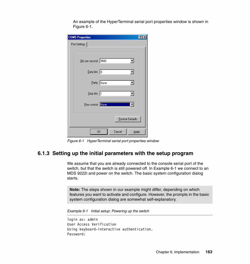
An example of the HyperTerminal serial port properties window is shown in Figure 6-1.
Figure 6-1 HyperTerminal serial port properties window
6.1.3 Setting up the initial parameters with the setup program
We assume that you are already connected to the console serial port of the switch, but that the switch is still powered off. In Example 6-1 we connect to an MDS 9222i and power on the switch. The basic system configuration dialog starts.
Example 6-1 Initial setup: Powering up the switch
login as: adminUser Access VerificationUsing keyboard-interactive authentication.Password:
Note: The steps shown in our example might differ, depending on which features you want to activate and configure. However, the prompts in the basic system configuration dialog are somewhat self-explanatory.
Chapter 6. Implementation 163

Cisco Nexus Operating System (NX-OS) SoftwareTAC support: http://www.cisco.com/tacCopyright (c) 2002-2008, Cisco Systems, Inc. All rights reserved.The copyrights to certain works contained in this software areowned by other third parties and used and distributed underlicense. Certain components of this software are licensed underthe GNU General Public License (GPL) version 2.0 or the GNULesser General Public License (LGPL) Version 2.1. A copy of eachsuch license is available athttp://www.opensource.org/licenses/gpl-2.0.php andhttp://www.opensource.org/licenses/lgpl-2.1.phpmds9222i-2# setup
---- Basic System Configuration Dialog ----
This setup utility will guide you through the basic configuration ofthe system. Setup configures only enough connectivity for managementof the system.
*Note: setup is mainly used for configuring the system initially,when no configuration is present. So setup always assumes systemdefaults and not the current system configuration values.
Press Enter at anytime to skip a dialog. Use ctrl-c at anytimeto skip the remaining dialogs.
Would you like to enter the basic configuration dialog (yes/no): yes
Do you want to enforce secure password standard (yes/no)[y]:
Create another login account (yes/no) [n]:
Configure read-only SNMP community string (yes/no) [n]:
Configure read-write SNMP community string (yes/no) [n]:
Enter the switch name : mds9222i-2
Continue with Out-of-band (mgmt0) management configuration? (yes/no) [y]:
Mgmt0 IPv4 address : 9.43.86.148
Mgmt0 IPv4 netmask : 255.255.252.0
164 Implementing an IBM/Cisco SAN

Configure the default gateway? (yes/no) [y]:
IPv4 address of the default gateway : 9.43.85.1
Configure advanced IP options? (yes/no) [n]: y
Continue with In-band (vsan1) management configuration? (yes/no) [n]:
Enable IP routing? (yes/no) [n]:
Configure static route? (yes/no) [n]:
Configure the default network? (yes/no) [n]:
Configure the DNS IPv4 address? (yes/no) [n]:
Configure the default domain name? (yes/no) [n]:
Enable the telnet service? (yes/no) [n]:
Enable the ssh service? (yes/no) [y]:
Type of ssh key you would like to generate (dsa/rsa) : dsa
Configure clock? (yes/no) [n]:
Configure timezone? (yes/no) [n]: y
Enter timezone config :PST
Configure summertime? (yes/no) [n]:
Configure the ntp server? (yes/no) [n]:
Configure default switchport interface state (shut/noshut) [shut]:
Configure default switchport trunk mode (on/off/auto) [on]:
Configure default switchport port mode F (yes/no) [n]:
Configure default zone policy (permit/deny) [deny]:
Enable full zoneset distribution? (yes/no) [n]:
Chapter 6. Implementation 165

Configure default zone mode (basic/enhanced) [basic]:
The following configuration will be applied: password strength-check switchname mds9222i-2 interface mgmt0 ip address 9.43.86.148 255.255.252.0 no shutdown ip default-gateway 9.43.85.1 no telnet server enable ssh key dsa force ssh server enable clock timezone PST system default switchport shutdown system default switchport trunk mode on no system default zone default-zone permit no system default zone distribute full no system default zone mode enhanced
Would you like to edit the configuration? (yes/no) [n]:
Use this configuration and save it? (yes/no) [y]: y
The basic configuration is now finished, and we can proceed to upgrade the SAN-OS or NX-OS to the latest available level.
6.1.4 Upgrading SAN-OS or NX-OS
In this section we upgrade the NX-OS Version 4.1(0.182) to the latest released level of NX-0S Version 4.1(1). This can be done using the Device Manager (DM) command-line interface (CLI) or the Fabric Manager (FM) graphical user interface (GUI). For completeness, we show how to perform the upgrade with both the CLI and the GUI.
Note: If you confirm to save the configuration in the last step, none of your changes are updated until the next time that the switch is rebooted. Ensure that you type yes here to save the new configuration.
166 Implementing an IBM/Cisco SAN

The CLI can be invoked by two methods on the Device Manager, as shown in Figure 6-2 and Figure 6-3.
Figure 6-2 Starting a command-line interface from Device Manager
Figure 6-3 Second method to start a command-line interface from a Device Manager
Upgrading the SAN-OS or NX-OS using the CLIPrior to upgrading the switch:
1. List the current SAN-OS or NX-OS version running on the switch.
2. Verify that there is sufficient free space in the bootflash to copy the necessary files over.
Chapter 6. Implementation 167

3. Copy the SAN-OS code from a FTP server to the bootflash on the switch, as shown in Example 6-2.
Example 6-2 Show the current SAN OS version
mds9222i-1# show versionCisco Nexus Operating System (NX-OS) SoftwareTAC support: http://www.cisco.com/tacCopyright (c) 2002-2008, Cisco Systems, Inc. All rights reserved.The copyrights to certain works contained herein are owned byother third parties and are used and distributed under license.Some parts of this software are covered under the GNU PublicLicense. A copy of the license is available athttp://www.gnu.org/licenses/gpl.html.
Software BIOS: version 1.0.15 loader: version N/A kickstart: version 4.1(1) [build 4.1(0.182)] [gdb] system: version 4.1(1) [build 4.1(0.182)] [gdb] BIOS compile time: 07/16/08 kickstart image file is: bootflash:/m9200-s2ek9-kickstart-mzg.4.1.0.182.bin kickstart compile time: 10/12/2020 25:00:00 [08/15/2008 18:42:09] system image file is: bootflash:/m9200-s2ek9-mzg.4.1.0.182.bin system compile time: 12/25/2010 12:00:00 [08/15/2008 20:03:21]
Hardware cisco MDS 9222i ("4x1GE IPS, 18x1/2/4Gbps FC/Sup2") Motorola, e500v2 with 1036512 kB of memory. Processor Board ID JAE12088ZMT
Device name: mds9222i-1 bootflash: 1000440 kBKernel uptime is 0 day(s), 0 hour(s), 3 minute(s), 38 second(s)
Last reset at 970000 usecs after Wed Sep 17 00:31:49 2008
Reason: Reset Requested by CLI command reload System version: 4.1(1) Service:
168 Implementing an IBM/Cisco SAN

You may list the active supervisor bootflash space, as shown in Example 6-3.
Example 6-3 Listing the active supervisors bootflash
mds9222i-1# dir bootflash: 25 Sep 11 02:16:32 2008 cpu_logfile 1024 Sep 11 06:40:00 2008 epld_dir/ 46080 Sep 17 00:24:31 2008 lost+found/ 3757210 Sep 11 02:06:49 2008 m9000-epld-4.1.1.img 19542528 Sep 11 02:08:00 2008 m9200-s2ek9-kickstart-mz.4.1.1.bin 19560960 Sep 17 00:23:42 2008 m9200-s2ek9-kickstart-mzg.4.1.0.182.bin 101905006 Sep 11 02:15:15 2008 m9200-s2ek9-mz.4.1.1.bin 106106231 Sep 17 00:22:14 2008 m9200-s2ek9-mzg.4.1.0.182.bin 1024 Sep 11 02:16:33 2008 partner/
Usage for bootflash://sup-local 295262208 bytes used 51566592 bytes free 346828800 bytes total
If needed, you may list the remote supervisor bootflash space as in a MDS 9513, which has dual supervisors. List the bootflash space as shown in Example 6-4.
Example 6-4 Listing the remote supervisors bootflash
mds9513-1# dir bootflash://sup-remote13017088 Jan 01 00:06:14 1970 bboot-3.2.1.23 31590136 Jan 01 00:08:09 1970 bdiag-3.2.1.23 4096 Jan 01 00:04:02 1970 boot/ 6 Jan 01 00:04:02 1970 cfglabel.sysmgr 25 Aug 18 05:58:30 2007 cpu_logfile 4096 Aug 18 06:12:44 2007 epld_dir/ 49152 Aug 24 05:46:26 2007 lost+found/ 3757210 Aug 18 06:12:01 2007 m9000-epld-4.1.1.img 19542528 Aug 18 05:50:02 2007 m9500-s2ek9-kickstart-mz.4.1.1.bin 19560960 Aug 24 05:45:49 2007 m9500-s2ek9-kickstart-mzg.4.1.0.182.bin 101905006 Aug 18 05:57:19 2007 m9500-s2ek9-mz.4.1.1.bin 106106231 Aug 24 05:45:11 2007 m9500-s2ek9-mzg.4.1.0.182.bin 4096 Aug 18 05:58:31 2007 partner/
Usage for bootflash://sup-local 367042560 bytes used 364429312 bytes free 731471872 bytes total
Chapter 6. Implementation 169

Copy the SAN-OS or NX-OS files from the FTP server to the bootflash in the switch, as shown in Example 6-5.
Ensure that the FTP server is reachable in order to copy the required files. Firewalls may prevent you from reaching the FTP server.
Example 6-5 Copy files to a remote server
mds9222i-1# copy ftp://9.43.86.49/jaco/4.1.1/m9200-s2ek9-kickstart-mz.4.1.1.bin bootflash:Enter username: jacoFile transfer in progress, please wait ...Password:mds9222i-1# copy ftp://9.43.86.49/jaco/4.1.1/m9200-s2ek9-mz.4.1.1.bin bootflash:Enter username: jacoFile transfer in progress, please wait ...Password:mds9222i-1#
Prior to starting the actual upgrade process, back up the running configuration to a FTP server, as shown in Example 6-6.
Example 6-6 Back up the running configuration
mds9222i-1# copy running-config ftp://9.43.86.49/jaco/backupEnter username: jacoPassword:mds9222i-1#
After backing up the configuration, start the upgrade using the install all command, as shown in Example 6-7.
Example 6-7 Upgrading the director using the install all command
mds9222i-1# install all system bootflash:m9200-s2ek9-mz.4.1.1.bin kickstart bootflash:m9200-s2ek9-kickstart-mz.4.1.1.bin
Verifying image bootflash:/m9200-s2ek9-kickstart-mz.4.1.1.bin for boot variable "kickstart".[####################] 100% -- SUCCESS
Note: A best practice when performing configuration changes is to always save the running configuration to the startup configuration. As a way of operation, you could also preserve the previous startup configurations for two generations.
170 Implementing an IBM/Cisco SAN

Verifying image bootflash:/m9200-s2ek9-mz.4.1.1.bin for boot variable "system".[####################] 100% -- SUCCESS
Verifying image type.[####################] 100% -- SUCCESS
Extracting "system" version from image bootflash:/m9200-s2ek9-mz.4.1.1.bin.[####################] 100% -- SUCCESS
Extracting "kickstart" version from image bootflash:/m9200-s2ek9-kickstart-mz.4.1.1.bin.[####################] 100% -- SUCCESS
Extracting "bios" version from image bootflash:/m9200-s2ek9-mz.4.1.1.bin.[####################] 100% -- SUCCESS
Extracting "slc2" version from image bootflash:/m9200-s2ek9-mz.4.1.1.bin.[####################] 100% -- SUCCESS
Performing Compact Flash and TCAM sanity test.[####################] 100% -- SUCCESS
Notifying services about system upgrade. [####################] 100% -- SUCCESS
Compatibility check is done:Module bootable Impact Install-type Reason------ -------- -------------- ------------ ------ 1 yes non-disruptive none 2 yes non-disruptive none
Do you want to continue with the installation (y/n)? [n] y
Install is in progress, please wait.
Setting boot variables.[####################] 100% -- SUCCESS
Performing configuration copy.[####################] 100% -- SUCCESS
Module 1: Refreshing compact flash and upgrading bios/loader/bootrom.Warning: please do not remove or power off the module at this time.[####################] 100% -- SUCCESS
Module 2: Refreshing compact flash and upgrading bios/loader/bootrom.Warning: please do not remove or power off the module at this time.[####################] 100% -- SUCCESS
Chapter 6. Implementation 171

Install has been successful.mds9222i-1#
After the upgrade has completed, we verify the version using the show version command, as shown in Example 6-8.
Example 6-8 Issuing show version after upgrade command
mds9222i-1# show versionCisco Nexus Operating System (NX-OS) SoftwareTAC support: http://www.cisco.com/tacCopyright (c) 2002-2008, Cisco Systems, Inc. All rights reserved.The copyrights to certain works contained herein are owned byother third parties and are used and distributed under license.Some parts of this software are covered under the GNU PublicLicense. A copy of the license is available athttp://www.gnu.org/licenses/gpl.html.
Software BIOS: version 1.0.15 loader: version N/A kickstart: version 4.1(1) system: version 4.1(1) BIOS compile time: 07/16/08 kickstart image file is: bootflash:/m9200-s2ek9-kickstart-mz.4.1.1.bin kickstart compile time: 10/12/2020 25:00:00 [09/09/2008 06:55:47] system image file is: bootflash:/m9200-s2ek9-mz.4.1.1.bin system compile time: 8/22/2008 0:00:00 [09/09/2008 08:15:09]
Hardware cisco MDS 9222i ("4x1GE IPS, 18x1/2/4Gbps FC/Sup2") Motorola, e500v2 with 1036316 kB of memory. Processor Board ID JAE12088ZMT
Device name: mds9222i-1 bootflash: 1000440 kBKernel uptime is 0 day(s), 0 hour(s), 1 minute(s), 59 second(s)
Last reset at 353970 usecs after Wed Sep 17 00:53:38 2008
172 Implementing an IBM/Cisco SAN

Reason: Reset Requested by CLI command reload System version: 4.1(0.182) Service:
The CLI can be used to delete old NX-OS files to free up bootflash space on the active supervisor if needed, as shown in Example 6-9.
Example 6-9 Freeing up bootflash space
mds9222i-1# dir bootflash: 25 Sep 11 02:16:32 2008 cpu_logfile 1024 Sep 11 06:40:00 2008 epld_dir/ 46080 Sep 17 00:47:28 2008 lost+found/ 3757210 Sep 11 02:06:49 2008 m9000-epld-4.1.1.img 19542528 Sep 17 00:41:54 2008 m9200-s2ek9-kickstart-mz.4.1.1.bin 19560960 Sep 17 00:23:42 2008 m9200-s2ek9-kickstart-mzg.4.1.0.182.bin 101905006 Sep 17 00:42:45 2008 m9200-s2ek9-mz.4.1.1.bin 106106231 Sep 17 00:22:14 2008 m9200-s2ek9-mzg.4.1.0.182.bin 1024 Sep 11 02:16:33 2008 partner/
Usage for bootflash://sup-local 295262208 bytes used 51566592 bytes free 346828800 bytes totalmds9222i-1# delete bootflash:m9200-s2ek9-kickstart-mzg.4.1.0.182.binmds9222i-1# delete bootflash:m9200-s2ek9-mzg.4.1.0.182.binmds9222i-1# dir bootflash: 25 Sep 11 02:16:32 2008 cpu_logfile 1024 Sep 11 06:40:00 2008 epld_dir/ 46080 Sep 17 00:47:28 2008 lost+found/ 3757210 Sep 11 02:06:49 2008 m9000-epld-4.1.1.img 19542528 Sep 17 00:41:54 2008 m9200-s2ek9-kickstart-mz.4.1.1.bin 101905006 Sep 17 00:42:45 2008 m9200-s2ek9-mz.4.1.1.bin 1024 Sep 11 02:16:33 2008 partner/
Usage for bootflash://sup-local 169098240 bytes used 177730560 bytes free 346828800 bytes total
Chapter 6. Implementation 173

The CLI can also be used to delete old SAN-OS or NX-OS files to free up bootflash space on the remote supervisor if needed, as shown in Example 6-10.
Example 6-10 Delete bootflash files on remote supervisor
mds9513# delete bootflash://sup-remote/m9200-s2ek9-mzg.4.1.0.182.binmds9513# delete bootflash://sup-remote/m9200-s2ek9-kickstart-mzg.4.1.0.182.binmds9513# dir bootflash://sup-remote
25 Sep 11 02:16:32 2008 cpu_logfile 1024 Sep 11 06:40:00 2008 epld_dir/ 46080 Sep 17 00:47:28 2008 lost+found/ 3757210 Sep 11 02:06:49 2008 m9000-epld-4.1.1.img 19542528 Sep 17 00:41:54 2008 m9500-s2ek9-kickstart-mz.4.1.1.bin 101905006 Sep 17 00:42:45 2008 m9500-s2ek9-mz.4.1.1.bin 1024 Sep 11 02:16:33 2008 partner/
Upgrading the SAN-OS and the NX-OS using the GUIIn the following example, we upgrade a director using the GUI, invoking the process using the Fabric Manager interface.
Note: When deleting files from the bootflash make sure that they will no longer be needed.
174 Implementing an IBM/Cisco SAN

To start the process, we invoke the Fabric Manager Software install wizard by clicking the icon shown in Figure 6-4.
Figure 6-4 Upgrade the SAN-OS or the NX-OS using Fabric Manager
Chapter 6. Implementation 175

In step 1, the Software Install wizard prompts us to select which switches we want to upgrade, and we click Next, as shown in Figure 6-5.
Figure 6-5 Selecting the switches to upgrade
176 Implementing an IBM/Cisco SAN

In step 2, the wizard prompts for the location of the software that we want to install. Specify the FTP server where the kickstart and system images reside, the size of the images, and login credentials for the FTP server, and click Next (Figure 6-6).
Figure 6-6 Specifying images and location
Note: The complete path to the file location must be specified for this step to complete successfully. Ensure that the firewall does not prevent access to the FTP server.
The wizard does not verify whether the images match the specified size, but the value is used to verify whether the amount of corresponding free space is available on the bootflash, prior to initiating the download.
Chapter 6. Implementation 177

In step 3, the software install wizard verifies whether the required free space is available on the bootflash, and we click Next, as shown in Figure 6-7.
Figure 6-7 Verifying required free space on bootflash
Should you encounter an insufficient amount of bootflash space you may take recovery action by clicking the Edit button, as suggested in Figure 6-8, or you may use the Device Manager option to delete bootflash files, as shown in Figure 6-9 on page 179 and Figure 6-10 on page 179.
Figure 6-8 Space recovery during the installation process
178 Implementing an IBM/Cisco SAN

Figure 6-9 Selecting FlashFiles in Device Manager to recover space in the bootflash
Figure 6-10 Select the files to delete
Chapter 6. Implementation 179

In step 4 we start the installation, as shown in Figure 6-11.
Figure 6-11 Starting the installation
If you want to perform the upgrade unattended, then in order to avoid being prompted to start the upgrade, you can check Ignore Versions Check Results, as shown in Figure 6-12.
Figure 6-12 Ignore versions check results
180 Implementing an IBM/Cisco SAN

In step 5 the image download starts and, upon completion, bootflash synchronization and compatibility checks are performed. When the wizard is ready to start the upgrade, we are prompted to click Yes (within a time-out period of 15 minutes) to start the upgrade, as shown in Figure 6-13.
Figure 6-13 Download and install status
Chapter 6. Implementation 181

In step 6, as the installation progresses, a step-by-step status is continuously displayed, as shown in Figure 6-14.
Figure 6-14 Monitoring installation progress
182 Implementing an IBM/Cisco SAN

In step 7, when the installation completes, the status of the upgrade is displayed, as shown in Figure 6-15.
Figure 6-15 Upgrade completed
6.1.5 Managing licensesTo obtain new or updated license key files:
1. Collect the host ID of the switch, also referred to as the switch serial number, using the command show license host-id from the CLI, as shown in Example 6-11. The host ID is FOX111504SL.
Example 6-11 Listing the switch serial number
mds9222i-2#mds9222i-2# show license host-idLicense hostid: VDH=FOX111504SLmds9222i-2#
Chapter 6. Implementation 183

This can also be done using the GUI, as shown in Figure 6-16. The Serial No Primary switch is equivalent to the license host_id.
Figure 6-16 Listing the serial number
2. Obtain your claim certificate or the proof of purchase document.
3. Locate the product authorization key (PAK) from the claim certificate or proof of purchase document.
4. Locate the Web site URL from the claim certificate or proof of purchase document.
5. Access the specified URL that applies to your switch and enter the switch serial number and the PAK.
The license key file is sent to you by e-mail. The license key file is digitally signed to only authorize use on the switch for which it was requested. The requested features are also enabled once the NX-OS or SAN-OS software on the specified switch accesses the license key file.
184 Implementing an IBM/Cisco SAN

When you have received your digitally signed license keys, they can be installed on the switch. The license files can be copied to the switch bootflash beforehand, or they can be copied during the install process.
Viewing installed licensesTo list the installed licenses on a switch, you can issue the command show license from the CLI or use GUI license selection or from the Device Manager by selecting Admin → Licenses, as shown in Figure 6-17.
Figure 6-17 Selecting the licensing interface
Chapter 6. Implementation 185

License features can be listed via the GUI, as shown in Figure 6-18.
Figure 6-18 License features
186 Implementing an IBM/Cisco SAN
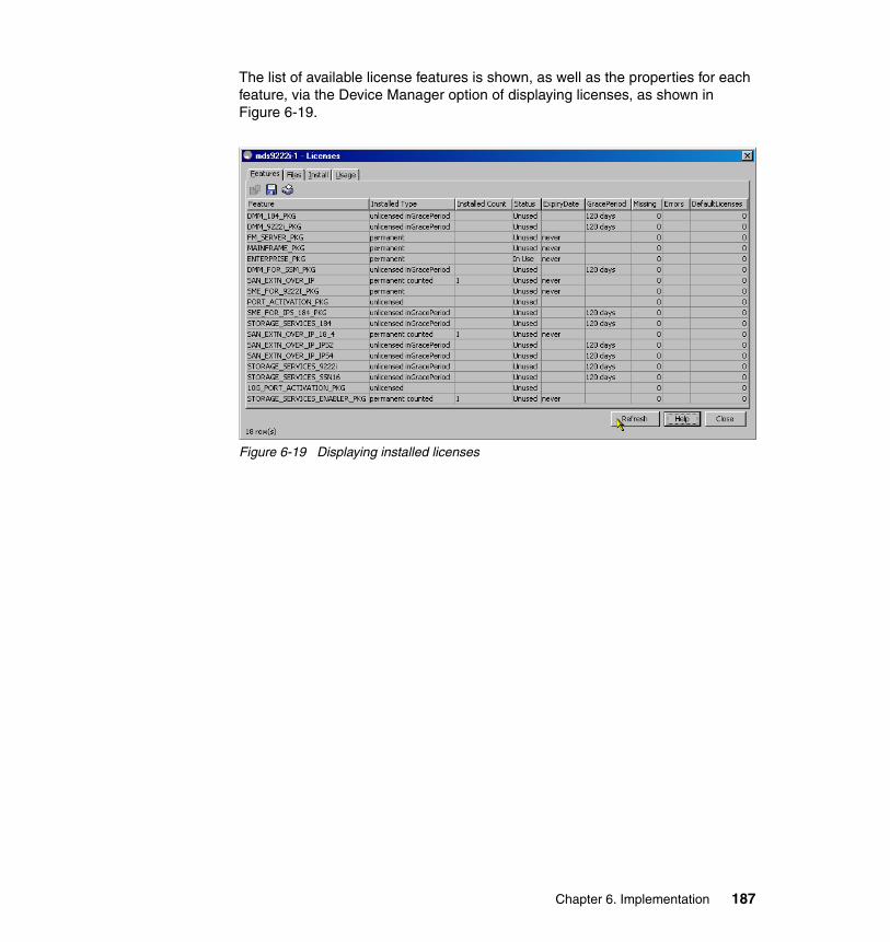
The list of available license features is shown, as well as the properties for each feature, via the Device Manager option of displaying licenses, as shown in Figure 6-19.
Figure 6-19 Displaying installed licenses
Chapter 6. Implementation 187

Copying files to the bootflash using the Device ManagerPrior to applying a license file, we upload it to the bootflash. In the window shown in Figure 6-20 select Admin → Flash Files in the Device Manager to invoke the Flash Files interface.
Figure 6-20 Starting the Flash Files interface
188 Implementing an IBM/Cisco SAN

The Flash Files interface is initialized as shown in Figure 6-21. Select the Copy option.
Figure 6-21 Selecting the copy option
When selecting the Copy option, when prompted, define the transfer protocol, server address, login credentials, and the source and target file names, and once done, click Apply to start the copy, as in Figure 6-22.
Figure 6-22 Specifying file to copy
Chapter 6. Implementation 189

Copy status notification is displayed in the bottom left of the Copy Files window, and upon completion we are notified that the file transfer was successful, as shown in Figure 6-23.
Figure 6-23 File transfer completed successfully
We have now transferred the license file to the bootflash, and we can proceed with installation of the license feature.
Note: During the execution of tasks using Device Manager occasionally prompts to provide CLI login credentials. This is because the Java applet issues the commands towards the SAN-OS/NX-OS using the CLI.
190 Implementing an IBM/Cisco SAN

Installing a license using the Device ManagerTo install:
1. To install a license on the switch, select the Install tab, as shown in Figure 6-24.
Figure 6-24 Selecting the Install panel
2. On the Install tab, click the pull-down icon to display available license files (in the bootflash), as shown in Figure 6-25.
Figure 6-25 Selecting a license file to install
Chapter 6. Implementation 191

3. Click Install to start the license file installation, as shown in Figure 6-26.
Figure 6-26 Installing the license file
4. Upon completion of the license file installation, click Refresh on the Feature tab, and verify that the desired feature has been activated, as shown in Figure 6-27.
Figure 6-27 Verifying the desired feature is activated
Installing a license using the CLIFirst we copy the license to the bootflash, as shown in Example 6-12.
Example 6-12 Copy license file to the bootflash and list files on the bootflash
mds9222i-2# show license host-idLicense hostid: VDH=FOX111504SLmds9222i-2# copy ftp://9.43.86.49/root/Lic/FOX111504SL.lic bootflash:
192 Implementing an IBM/Cisco SAN

Enter username: rootFile transfer in progress, please wait ...Password:mds9222i-2# dir bootflash: 1567 Aug 26 04:26:13 2007 FOX111504SL.lic 4096 Jan 01 00:04:02 1970 boot/ 6 Jan 01 00:04:02 1970 cfglabel.sysmgr 25 Aug 18 05:58:30 2007 cpu_logfile 4096 Aug 18 06:12:44 2007 epld_dir/ 49152 Aug 25 00:27:53 2007 lost+found/ 19542528 Aug 24 07:17:41 2007 m9200-s2ek9-kickstart-mz.4.1.1.bin 101905006 Aug 24 07:17:33 2007 m9200-s2ek9-mz.4.1.1.bin 4096 Aug 18 05:58:31 2007 partner/
Usage for bootflash://sup-local 192811008 bytes used 538660864 bytes free 731471872 bytes total
Subsequently, install the received license on the switch and then display the installed licenses, as shown in Example 6-13.
Example 6-13 Installing the Fabric Manager Server license
mds9222i-2# show license host-idLicense hostid: VDH=FOX111504SLmds9222i-2# show licensemds9222i-2# install license bootflash:FOX111504SL.licInstalling license .....donemds9222i-2# show licenseFOX111504SL.lic:SERVER this_host ANYVENDOR ciscoINCREMENT FM_SERVER_PKG cisco 1.0 permanent uncounted \ VENDOR_STRING=MDS HOSTID=VDH=FOX111504SL \NOTICE="<LicFileID>FOX111504SL.lic</LicFileID><LicLineID>0</LicLineID> \ <PAK>dummyPak</PAK>" SIGN=F08238B68D9EINCREMENT MAINFRAME_PKG cisco 1.0 permanent uncounted \ VENDOR_STRING=MDS HOSTID=VDH=FOX111504SL \NOTICE="<LicFileID>FOX111504SL.lic</LicFileID><LicLineID>1</LicLineID> \ <PAK>dummyPak</PAK>" SIGN=9EADA1E472C6INCREMENT ENTERPRISE_PKG cisco 1.0 permanent uncounted \ VENDOR_STRING=MDS HOSTID=VDH=FOX111504SL \NOTICE="<LicFileID>FOX111504SL.lic</LicFileID><LicLineID>2</LicLineID> \ <PAK>dummyPak</PAK>" SIGN=BEE71C380B56INCREMENT SAN_EXTN_OVER_IP cisco 1.0 permanent 1 VENDOR_STRING=MDS \ HOSTID=VDH=FOX111504SL \NOTICE="<LicFileID>FOX111504SL.lic</LicFileID><LicLineID>3</LicLineID> \ <PAK>dummyPak</PAK>" SIGN=12060E603650
Chapter 6. Implementation 193

INCREMENT SAN_EXTN_OVER_IP_18_4 cisco 1.0 permanent 1 \ VENDOR_STRING=MDS HOSTID=VDH=FOX111504SL \NOTICE="<LicFileID>FOX111504SL.lic</LicFileID><LicLineID>4</LicLineID> \ <PAK>dummyPak</PAK>" SIGN=C811C45CAC88INCREMENT STORAGE_SERVICES_ENABLER_PKG cisco 1.0 permanent 1 \ VENDOR_STRING=MDS HOSTID=VDH=FOX111504SL \NOTICE="<LicFileID>FOX111504SL.lic</LicFileID><LicLineID>5</LicLineID> \ <PAK>dummyPak</PAK>" SIGN=0B949EC6009AINCREMENT SME_FOR_9222I_PKG cisco 1.0 permanent uncounted \ VENDOR_STRING=MDS HOSTID=VDH=FOX111504SL \NOTICE="<LicFileID>FOX111504SL.lic</LicFileID><LicLineID>6</LicLineID> \ <PAK>dummyPak</PAK>" SIGN=0B47CB66112E
mds9222i-2# show license briefFOX111504SL.licmds9222i-2# show license usageFeature Ins Lic Status Expiry Date Comments Count-------------------------------------------------------------------------------DMM_184_PKG No 0 Unused Grace 120D 0HDMM_9222i_PKG No 0 Unused Grace 120D 0HFM_SERVER_PKG Yes - Unused never -MAINFRAME_PKG Yes - Unused never -ENTERPRISE_PKG Yes - In use never -DMM_FOR_SSM_PKG No 0 Unused Grace 120D 0HSAN_EXTN_OVER_IP Yes 1 Unused never -SME_FOR_9222I_PKG Yes - Unused never -PORT_ACTIVATION_PKG No 0 Unused -SME_FOR_IPS_184_PKG No 0 Unused Grace 120D 0HSTORAGE_SERVICES_184 No 0 Unused Grace 120D 0HSAN_EXTN_OVER_IP_18_4 Yes 1 Unused never -SAN_EXTN_OVER_IP_IPS2 No 0 Unused Grace 120D 0HSAN_EXTN_OVER_IP_IPS4 No 0 Unused Grace 120D 0HSTORAGE_SERVICES_9222i No 0 Unused Grace 120D 0HSTORAGE_SERVICES_SSN16 No 0 Unused Grace 120D 0H10G_PORT_ACTIVATION_PKG No 0 Unused -STORAGE_SERVICES_ENABLER_PKG Yes 1 Unused never --------------------------------------------------------------------------------
6.1.6 Managing usersWhen accessing Cisco MDS 9000 family switches, you are required to authenticate with a user name and a password, after which access is granted and role-based authorization is applied.
194 Implementing an IBM/Cisco SAN

AuthenticationUser authentication can be configured to be performed locally on the switch (in the lookup database) or remotely using one or more RADIUS, TACACS+ servers, or MDS.
In the following section we authenticate using local authentication. For detailed information about how to set up remote authentication (RADIUS, TACACS+, MDS) consult the MDS config-guide:
http://www.cisco.com/en/US/products/ps5989/products_installation_and_configuration_guides_list.html
AuthorizationBy default the two roles, network-operator and network-admin, exist in all Cisco MDS 9000 family switches and cannot be changed or deleted, although you can create other roles:
� Network-operator
Has permission to view the configuration only and cannot make any configuration changes.
� Network-admin
Has permission to execute all commands and configuration changes. The administrator has the permission to create up to 64 additional roles.
Creating rolesTo create a role, we define the name of the role and the profile, which specifies the permissions for the role. In Example 6-14 we create the ITSO_role role and give this administrator access only to VSANs 10 and 20.
Finally, we issue the command show role to list defined roles.
Example 6-14 Creating a VSAN role
mds9222i-2# configure terminalmds9222i-2(config)# role name ITSO_rolemds9222i-2(config-role)# description Admin for VSAN10_VSAN20mds9222i-2(config-role)# role name ITSO_rolemds9222i-2(config-role)# vsan policy denyafter grace period of approximately 120 day(s).mds9222i-2(config-role-vsan)# permit vsan 10
Note: It is possible to disable login authentication, although we do not recommend it.
Chapter 6. Implementation 195

mds9222i-2(config-role-vsan)# permit vsan 20
mds9222i-2# show role
Role: network-adminDescription: Predefined Network Admin group. This role cannot be modifiedAccess to all the switch commands
Role: network-operatorDescription: Predefined Network Operator group. This role cannot be modifiedAccess to Show commands and selected Exec commands
Role: server-admin Description: Predefined system role for server administrators. This role cannot be modified. Vsan policy: permit (default) ------------------------------------------------- Rule Type Command-type Feature ------------------------------------------------- 1 permit show * 2 permit exec install
Role: default-role Description: This is a system defined role and applies to all users. Vsan policy: permit (default) ------------------------------------------------- Rule Type Command-type Feature ------------------------------------------------- 1 permit show system 2 permit show snmp 3 permit show module 4 permit show hardware 5 permit show environment
Role: ITSO_role Description: Admin for VSAN10_VSAN20 Vsan policy: deny Permitted vsans: 10,20
196 Implementing an IBM/Cisco SAN

To perform the same configuration using Fabric Manager:
1. Click the users and roles icon, as shown in Figure 6-28.
Figure 6-28 Selecting users and roles
2. Select the Roles tab and click the create row icon, as shown in Figure 6-29.
Figure 6-29 Selecting create row in the Fabric Manager
Chapter 6. Implementation 197

3. In the role creation window, define the name of the role and the VSAN properties, as shown in Figure 6-30, and click Create.
Figure 6-30 Defining a new role
After closing the role creation window, see that the created role is now listed, as shown in Figure 6-31.
Figure 6-31 Listing the defined roles
198 Implementing an IBM/Cisco SAN

Creating usersTo create a user define the name of the user and the profiles, which specifies the permissions for the user. In Example 6-14 on page 195 the role ITSO_role has been created. Now apply the ITSO_role to the ITSO_user, which only has permissions for VSANs 10 and 20, as shown in Example 6-15.
Example 6-15 Creating a user
mds9222i-2# configure terminalmds9222i-2(config)# username ITSO_user password confidential role ITSO_role
mds9222i-2# show user-accountuser:admin this user account has no expiry date roles:network-adminuser:ITSO_user this user account has no expiry date roles:ITSO_roleuser:jaco this user account has no expiry date roles:network-admin
To create the same user using Fabric Manager:
1. Click the users and roles icon, as shown earlier in Figure 6-28 on page 197.
2. Select the Users tab and click the create row icon, as shown in Figure 6-32.
Figure 6-32 Selecting create row icon
Chapter 6. Implementation 199

3. In the user creation window define the name of the user and the roles to apply, as shown in Figure 6-33, and click Create.
Figure 6-33 Creating a new user using Fabric Manager
As you can see, we have the option to define an expiry date for the user that we create. To delete a user, we simply delete the row of the user to be deleted.
For further details on user and host creation, consult the MDS Cisco Configuration Guide:
http://www.cisco.com/en/US/products/ps5989/products_installation_and_configuration_guides_list.html
6.1.7 VSANA Virtual Storage Area Network (VSAN) is a unique feature of the Cisco MDS 9000 family that enables dividing the physical Fibre Channel fabric into virtual SAN fabrics. Each VSAN is a completely separate SAN fabric, with its own set of domain IDs, fabric services, zones, namespace, and interoperability mode.
200 Implementing an IBM/Cisco SAN

Each port in the switch fabric belongs to exactly one of the VSANs at any given time, with the exception of trunking E_Ports (TE_Ports) that can multiplex the traffic of several VSANs over a single physical link.
Up to 256 VSANs can be configured in a single switch. The VSAN numbers can range from 1 to 4094. VSAN number 1 is called the default VSAN and is the VSAN that initially contains all of the ports in the switch. If you do not have to divide the fabric into VSANs, you can leave all ports in the default VSAN.
The VSAN number 4094 is called the isolated VSAN, and any port configured into that VSAN is isolated from all other ports. If you delete a VSAN, all ports in it are moved to the isolated VSAN to avoid implicit transfer of the ports to the default VSAN.
Creating a VSAN using the CLIWhen creating a VSAN, assign a VSAN ID and (optional) name, which must be unique. In Example 6-16 VSAN 20 and VSAN 30 have been created with names ITSO_VSAN_20 and ITSO_VSAN_30, using the default setting for interoperability and load balancing, then suspend it. After creating VSANs, list the defined VSANs.
Example 6-16 Creating a VSAN
mds9222i-1(config)# vsan databasemds9222i-1(config-vsan-db)# vsan 20 name ITSO_VSAN_20mds9222i-1(config-vsan-db)# vsan 30 name ITSO_VSAN_30
mds9222i-1# show vsanvsan 1 information name:VSAN0001 state:active interoperability mode:default loadbalancing:src-id/dst-id/oxid operational state:up
vsan 10 information name:ITSO_VSAN_10 state:active interoperability mode:default loadbalancing:src-id/dst-id/oxid
Note: A best practice for a large SAN environment is not to use VSAN1 while disallowing communication between ports that are not defined in a zone (at setup this is defined as default zone policy deny) and additionally not define any zones in VSAN1. Doing this prevents any accidental communication of new devices or hosts attached to the fabric since they by default belong to VSAN1.
Chapter 6. Implementation 201

operational state:up
vsan 20 information name:ITSO_VSAN_20 state:active interoperability mode:default loadbalancing:src-id/dst-id/oxid operational state:up
vsan 30 information name:ITSO_VSAN_30 state:active interoperability mode:default loadbalancing:src-id/dst-id/oxid operational state:up
vsan 4094:isolated_vsan
Assigning ports to a VSANNow that new VSANs have been created assign membership to the VSANs of ports fc1/5-8,16 to the VSAN 20 and fc1/9-12,17 to the VSAN 30. Afterwards list the VSANs memberships, as shown in Example 6-17.
Example 6-17 Assigning membership to a VSAN
mds9222i-1# config terminalmds9222i-1(config)# vsan databasemds9222i-1(config-vsan-db)# vsan 20 interface fc 1/5-8mds9222i-1(config-vsan-db)# vsan 20 interface fc 1/16mds9222i-1(config-vsan-db)# vsan 30 interface fc 1/9-12mds9222i-1(config-vsan-db)# vsan 30 interface fc 1/17
mds9222i-1# show vsan membershipvsan 1 interfaces: fc1/13 fc1/15 fc1/18 fc2/1 fc2/2 fc2/3 fc2/4 fc2/5 fc2/6 fc2/7 fc2/8 fc2/9 fc2/10 fc2/11 fc2/12 fc2/13 fc2/14 fc2/15 fc2/16 fc2/17 fc2/18 fc2/19 fc2/20 fc2/21 fc2/22 fc2/23 fc2/24 fc2/25 fc2/26 fc2/27 fc2/28 fc2/29 fc2/30 fc2/31 fc2/32 fc2/33 fc2/34 fc2/35 fc2/36 fc2/37 fc2/38 fc2/39 fc2/40 fc2/41 fc2/42 fc2/43 fc2/44 fc2/45 fc2/46 fc2/47 fc2/48 port-channel 1
vsan 10 interfaces:
202 Implementing an IBM/Cisco SAN

fc1/1 fc1/2 fc1/3 fc1/4 fc1/14
vsan 20 interfaces: fc1/5 fc1/6 fc1/7 fc1/8 fc1/16
vsan 30 interfaces: fc1/9 fc1/10 fc1/11 fc1/12 fc1/17
vsan 4094(isolated_vsan) interfaces:
Creating a VSAN using the GUIPerform the same task using the Fabric Manager interface:
1. Click the create VSAN icon, as shown in Figure 6-34.
Figure 6-34 Creating a VSAN from a GUI
Note: When assigning port membership to a VSAN, the port is removed from its previous membership, since a port can only be part of one VSAN at a time.
Chapter 6. Implementation 203

2. In the Create VSAN window specify the VSAN ID name, load balancing and interop properties, and whether the VSAN should be active or suspended. To enforce static domain IDs, check the Static Domain Ids box, as shown in Figure 6-35.
Figure 6-35 Assigning VSAN ID and name
204 Implementing an IBM/Cisco SAN

3. If necessary, use static domain IDs, so check this box and click Apply to get a static domain ID assigned on the switch, as shown in Figure 6-36. Then click Create to create the VSAN.
Figure 6-36 Applying static domains
The VSAN has now been created and appears in Fabric Manager. As shown in Figure 6-37, the VSAN is down, since we have not yet assigned any ports to the VSAN. Thus, there are no active ports in the VSAN.
Figure 6-37 VSAN created: VSAN is down while empty
Chapter 6. Implementation 205

Assigning ports to a VSANSince a host and device are already connected to the switch:
1. Highlight FC Interfaces in VSAN001 to list the ports that are required to assign to the created VSAN, as shown in Figure 6-38.
Figure 6-38 Listing devices in VSAN1
2. Double-click the Port VSAN cell and change the VSAN ID to the VSAN ID of the VSAN that is required to assign the port to, and subsequently click the apply changes icon to save the changes, as shown in Figure 6-39.
Figure 6-39 Changing the VSAN ID for a port to assign it to the VSAN
206 Implementing an IBM/Cisco SAN

3. We are presented with a warning that changing the Port VSAN might be disruptive to I/O on the port, and we confirm that we want to perform the change, as shown in Figure 6-40.
Figure 6-40 Confirm to change the Port VSAN
4. When this is completed, list the ports in our VSAN, as shown in Figure 6-41, and the VSAN is now up, since active ports are present in the VSAN.
Figure 6-41 Listing ports in the our new VSAN
Dynamic VSANsPort VSAN membership on the switch is assigned on a port-by-port basis. By default each port belongs to the default VSAN.
Chapter 6. Implementation 207

You can dynamically assign VSAN membership to ports by assigning VSANs based on the device WWN. This method is referred to as the Dynamic Port VSAN Membership (DPVM) feature. DPVM offers flexibility and eliminates the necessity to reconfigure the VSAN to maintain fabric topology when a host or storage device connection is moved between two Cisco MDS switches. It retains the configured VSAN regardless of where a device is connected or moved.
About DPVMDPVM configurations are based on port world wide name (pWWN) and node world wide name (nWWN) assignments. A DPVM database contains mapping information for each device pWWN/nWWN assignment and the corresponding VSAN. The Cisco SAN-OS and NX-OS software checks the database during a device FLOGI and obtains the required VSAN details.
The pWWN identifies the host or device and the nWWN identifies a node consisting of multiple devices. You can assign any one of these identifiers or any combination of these identifiers to configure DPVM mapping. If you assign a combination, then preference is given to the pWWN. DPVM uses the Cisco Fabric Services (CFS) infrastructure to allow efficient database management and distribution. DPVM uses the application-driven, coordinated distribution mode and the fabric-wide distribution scope.
DPVM requirementsTo use the DPVM feature as designed, be sure to verify the following requirements:
� The interface through which the dynamic device connects to the Cisco MDS 9000 family switch must be configured as an F port.
� The static port VSAN of the F port should be valid (not isolated, not suspended, and in existence).
� The dynamic VSAN configured for the device in the DPVM database should be valid (not isolated, not suspended, and in existence).
Enabling DPVMTo begin configuring the DPVM feature, you must explicitly enable DPVM on the required switches in the fabric. By default, this feature is disabled in all switches in the Cisco MDS 9000 family. The configuration and verification commands for the DPVM feature are only available when DPVM is enabled on a switch. When you disable this feature, all related configurations are automatically discarded.
Note: The DPVM feature overrides any existing static port VSAN membership configuration. If the VSAN corresponding to the dynamic port is deleted or suspended, the port is shut down.
208 Implementing an IBM/Cisco SAN

To use DPVM using the GUI:
1. Click the DPVM icon, as shown in Figure 6-42.
Figure 6-42 Launching the DPVM wizard
2. Select the switch that is required to be the master DPVM switch and click Next, as shown in Figure 6-43.
Figure 6-43 Selecting the master switch for DPVM
Chapter 6. Implementation 209

3. Select to create the configuration from already logged-in devices, as shown in Figure 6-44.
Figure 6-44 Creating configuration from end devices currently logged in
210 Implementing an IBM/Cisco SAN

4. As shown in Figure 6-45, click Finish to activate the configuration.
Figure 6-45 Edit and activate configuration
6.1.8 ZoningThe Cisco MDS 9000 family zoning can be administrated from any switch in the fabric, and all changes are automatically distributed to all of the switches.
The Cisco MDS 9000 family supports zoning by the following criteria:
� World Wide Port Name (WWPN): The WWN of the Nx_Port (device) attached to the switch.
� Fabric Port WWN (fWWN): The WWN of the fabric port (port-based zoning).
� FCID: The FCID of the N_Port attached to the switch.
� FC alias: The alias used.
� Domain ID: Where the domain ID is the domain ID of a switch.
Chapter 6. Implementation 211

� IP address: Where the IP address of the devices is entered as a 32-byte dotted decimal optionally specifying a subnet mask that includes all addresses in the specified subnet.
� Interface: Switch interface zoning is similar to port zoning and can be defined as a zone member on both a local and a remote switch. This type of zoning is for iSCSI initiators.
To make zone management easier, the Cisco MDS 9000 family supports alias names for practically all of the elements above.
The Cisco MDS 9000 family supports a default zone. All ports and WWNs not assigned to any zone belong to the default zone. If zoning is not activated, all devices belong to the default zone. You can control access between default zone members by default zone policy. This is both a per-switch (defined at setup) and a per-VSAN setting. The default is deny, but can be changed using the config command zone default-zone permit. In Example 6-18 we set the default zone policy to permit for VSAN20.
Example 6-18 Setting the default zone policy for a VSAN
mds9222i-1# configure terminalmds9222i-1(config)# zone default-zone permit vsan 20
The Cisco MDS 9000 family supports both soft and hard zoning. The difference between soft and hard zone enforcement is described below.
Soft zoningIn soft zoning, zoning restrictions are applied during the interaction between the name server and the end device.
Hard zoningIn hard zoning, the zoning is enforced for each frame sent by an Nx_Port as the frame enters the switch. This prevents any unauthorized access at all times. The enforcement is done by the switch hardware at wire speed.
6.1.9 Zoning using the CLIWhen creating zoning, we recommend that you use aliases, since this eases administration and troubleshooting, especially when your SAN environment increases in size.
AliasAlias members can be assigned to an alias based on FC ID, fabric port WWN, or WWPN.
212 Implementing an IBM/Cisco SAN

Next we list the entries in the name server and create the aliases SVC2_NODE1_FCS0 and PALAU_FCS0, assigning the FC IDs of the ports the hosts are attached to, as shown in Example 6-19.
Example 6-19 Creating an alias and assigning a member based on FC ID
mds9222i-1# show fcns database vsan 20
VSAN 20:--------------------------------------------------------------------------FCID TYPE PWWN (VENDOR) FC4-TYPE:FEATURE--------------------------------------------------------------------------0x9c0001 N 50:05:07:68:01:30:1d:21 (IBM) scsi-fcp:target0x9c0003 N 50:05:07:68:01:30:1d:22 (IBM) scsi-fcp:target0x9c0004 N 50:05:07:68:01:10:1d:22 (IBM) scsi-fcp:target0x9c000e N 50:05:07:68:01:10:1d:21 (IBM) scsi-fcp:target0x9c0100 N 21:00:00:e0:8b:05:4c:aa (Qlogic) scsi-fcp:init
Total number of entries = 5mds9222i-1# configure terminalmds9222i-1(config)# fcalias name SVN2_NODE1_FCS0 vsan 20mds9222i-1(config-fcalias)# member fcid 0x9c0004mds9222i-1(config-fcalias)# exitmds9222i-1(config)# fcalias name PALAU_FCS0 vsan 20mds9222i-1(config-fcalias)# member fcid 0x9c0100mds9222i-1(config-fcalias)# endmds9222i-1# show fcalias vsan 20fcalias name PALAU_FCS0 vsan 20 fcid 0x9c0100
fcalias name SVN2_NODE1_FCS0 vsan 20 fcid 0x9c0004
ZonesWhen creating a zone, we recommend zones based on aliases, and in the following coding, we create a zone called SVC2_NODE1_FCS0_PALAU_FCS0 for PALAU to access SVC2_NODE1_FCS0. As shown in Example 6-20, we create the zone and subsequently list defined zones.
Example 6-20 Creating a zone
mds9222i-1# configure terminalmds9222i-1(config)# zone name SVC2_NODE1_FCS0_PALAU_FCS0 vsan 20mds9222i-1(config-zone)# member fcalias PALAU_FCS0mds9222i-1(config-zone)# member fcalias SVN2_NODE1_FCS0mds9222i-1(config-zone)# endmds9222i-1# show zone vsan 20zone name SVC2_NODE1_FCS0_PALAU_FCS0 vsan 20
Chapter 6. Implementation 213

fcalias name SVN2_NODE1_FCS0 vsan 20 fcid 0x9c0004
fcalias name PALAU_FCS0 vsan 20 fcid 0x9c0100
For the zone to become active, we must then assign the zone to a zoneset and activate the zoneset.
ZonesetWhereas a zone is used to specify access control, confining the specified members in a zone, zonesets are used to group zones and to enforce the access control defined by each zone when the zoneset is activated.
To create a zoneset specify the name, VSAN, and members of the zoneset. In Example 6-21 we create the zoneset ZonesetActive2 and add the zone SVC2_NODE1_FCS0_PALAU_FCS0, and subsequently list the zoneset.
Example 6-21 Creating a zoneset
sc9222i-1# sho zonesetZoneset not present
mds9222i-1# configure terminalEnter configuration commands, one per line. End with CNTL/Z.mds9222i-1(config-zoneset)# member SVC2_NODE1_FCS0_PALAU_FCS0mds9222i-1(config-zoneset)# endzoneset name ZonesetActive2 vsan 20 zone name SVC2_NODE1_FCS0_PALAU_FCS0 vsan 20 fcalias name SVN2_NODE1_FCS0 vsan 20 fcid 0x9c0004
fcalias name PALAU_FCS0 vsan 20 fcid 0x9c0100
Before a zoneset is enforced, it must be activated. To activate a zoneset specify a zoneset and a VSAN. In Example 6-22 we first list active zonesets, then we activate the zoneset ZonesetActive2 in VSAN20, and subsequently list active zonesets.
Example 6-22 Activating a zoneset
sc9222i-1# sho zoneset activeZoneset not present
mds9222i-1# configure terminalmds9222i-1(config)# zoneset activate name ZonesetActive2 vsan 20
214 Implementing an IBM/Cisco SAN

Zoneset activation initiated. check zone statusmds9222i-1(config)# endmds9222i-1# show zoneset active vsan 20
zoneset name ZonesetActive2 vsan 20 zone name SVC2_NODE1_FCS0_PALAU_FCS0 vsan 20 * fcid 0x9c0004 * fcid 0x9c0100
When working with zonesets, it is crucial to understand that while you can create multiple zonesets (and zones can be members of multiple zonesets), only one zoneset can be active at any given time (for each VSAN).
When creating a zoneset, the zoneset becomes part of the full zoneset, and when activating a zoneset, a copy of the zoneset from the full zoneset is activated and the member zones become active.
Although the active zoneset cannot be modified, we can modify the full zoneset, and even a zoneset with the same name. However, modifications only take effect when reactivated.
While the zoneset is active, it is automatically stored in the persistent configuration. It is not necessary to copy the running-config to the startup-config, though changes to inactive zonesets are not automatically saved to the startup-config unless you perform this by issuing the copy running-config startup config command.
6.1.10 Zoning using the GUIWhen creating zoning, we recommend that you use aliases, since this eases administration and troubleshooting, especially when your SAN environment increases in size.
AliasAlias members can be assigned to an alias based on FC ID, fabric port WWN, or WWPN.
Note: In the following sections we go through the examples mainly by right-clicking the objects that we want to alter. When you become more familiar with the GUI, you will see that there are multiple ways to perform the same task, and that drag-and-drop is also available for many tasks.
Chapter 6. Implementation 215

In the following example we create two aliases, SVC3_NODE1_FCS0 and SIAM_FCS0, and assign the WWPNs of the SVC and a host adapter.
1. As shown in Figure 6-46, right-click the VSAN to select to edit the full zoneset.
Figure 6-46 Edit full zone database for VSAN 30
216 Implementing an IBM/Cisco SAN

2. In the edit full zoneset database right-click Aliases to insert a new alias, as shown in Figure 6-47.
Figure 6-47 Inserting a new alias
3. In the Create Alias window, name the alias and assign the WWPN (selected from the drop-down menu) and click OK, as shown in Figure 6-48.
Figure 6-48 Creating alias based on WWPN
Then we create the alias SVC3_NODE1_FCS0, assigning the FC ID of the port that the host is attached to as a member.
Chapter 6. Implementation 217

4. Click Insert to create a new FC Alias, as shown in Figure 6-49.
Figure 6-49 Clicking insert
5. Name the new alias SVC3_NODE1_FCS0 and click OK to create the empty alias, as shown in Figure 6-50.
Figure 6-50 Defining an empty alias
218 Implementing an IBM/Cisco SAN
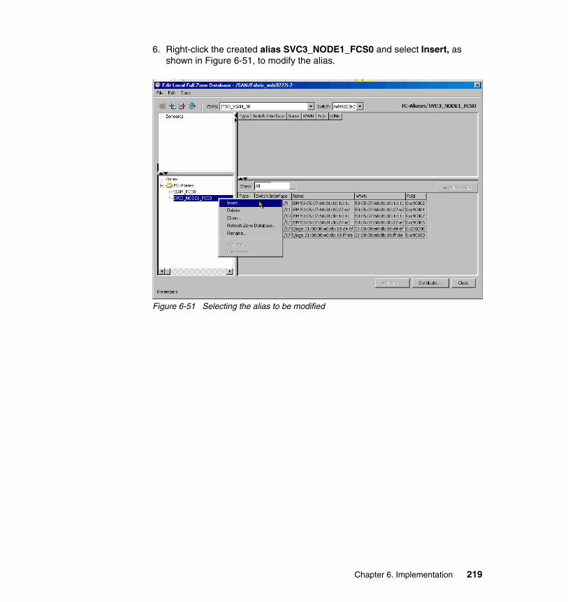
6. Right-click the created alias SVC3_NODE1_FCS0 and select Insert, as shown in Figure 6-51, to modify the alias.
Figure 6-51 Selecting the alias to be modified
Chapter 6. Implementation 219

7. To define the alias member, we mark the FCID and click the select end device icon, as shown in Figure 6-53.
Figure 6-52 Select membership type and end device
8. Highlight the desired end device and click OK, as shown in Figure 6-53.
Figure 6-53 Selecting the end device
220 Implementing an IBM/Cisco SAN

9. We have now defined the properties for the alias member Host_A. Click Add, as shown in Figure 6-54.
Figure 6-54 Add the alias member
10.Finally, we list the defined aliases and verify that they are created as we intended, as shown in Figure 6-55 and Figure 6-56 on page 222.
Figure 6-55 Listing defined aliases
Chapter 6. Implementation 221
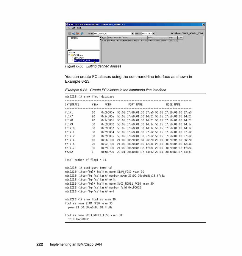
Figure 6-56 Listing defined aliases
You can create FC aliases using the command-line interface as shown in Example 6-23.
Example 6-23 Create FC aliases in the command-line interface
mds9222i-1# show flogi database--------------------------------------------------------------------------------INTERFACE VSAN FCID PORT NAME NODE NAME--------------------------------------------------------------------------------fc1/1 10 0x0b000a 50:05:07:68:01:10:37:e5 50:05:07:68:01:00:37:e5fc1/7 20 0x9c000e 50:05:07:68:01:10:1d:21 50:05:07:68:01:00:1d:21fc1/8 20 0x9c0001 50:05:07:68:01:30:1d:21 50:05:07:68:01:00:1d:21fc1/9 30 0xc90002 50:05:07:68:01:10:1d:1c 50:05:07:68:01:00:1d:1cfc1/10 30 0xc90007 50:05:07:68:01:30:1d:1c 50:05:07:68:01:00:1d:1cfc1/11 30 0xc90004 50:05:07:68:01:10:27:e2 50:05:07:68:01:00:27:e2fc1/12 30 0xc90005 50:05:07:68:01:30:27:e2 50:05:07:68:01:00:27:e2fc1/14 10 0x0b0100 21:00:00:e0:8b:89:2b:cd 20:00:00:e0:8b:89:2b:cdfc1/16 20 0x9c0100 21:00:00:e0:8b:05:4c:aa 20:00:00:e0:8b:05:4c:aafc1/17 30 0xc90100 21:00:00:e0:8b:18:ff:8a 20:00:00:e0:8b:18:ff:8afc2/2 1 0xad0f00 20:04:00:a0:b8:17:44:32 20:04:00:a0:b8:17:44:31
Total number of flogi = 11.
mds9222i-1# configure terminalmds9222i-1(config)# fcalias name SIAM_FCS0 vsan 30mds9222i-1(config-fcalias)# member pwwn 21:00:00:e0:8b:18:ff:8amds9222i-1(config-fcalias)# exitmds9222i-1(config)# fcalias name SVC3_NODE1_FCS0 vsan 30mds9222i-1(config-fcalias)# member fcid 0xc90002mds9222i-1(config-fcalias)# end
mds9222i-1# show fcalias vsan 30fcalias name SIAM_FCS0 vsan 30 pwwn 21:00:00:e0:8b:18:ff:8a
fcalias name SVC3_NODE1_FCS0 vsan 30 fcid 0xc90002
222 Implementing an IBM/Cisco SAN

ZonesIn order to create a zone:
1. Right-click Zones to insert a new zone, as shown in Figure 6-57.
Figure 6-57 Creating a new zone using the GUI
2. Name the new zone and apply specific properties for the zone such as Read Only, QoS, and broadcast frame restrictions, as shown in Figure 6-58. We name the zone SVC3_NODE1_FCS0_SIAM_FCS0 with default zone properties and click OK.
Figure 6-58 Naming a new zone
Chapter 6. Implementation 223

3. Right-click the created zone and select Insert to define members of the zone, as shown in Figure 6-59.
Figure 6-59 Select a zone to be modified
224 Implementing an IBM/Cisco SAN

4. Select FC-Alias to add as members and then click the select devices icon to list available aliases, as shown in Figure 6-60.
Figure 6-60 Selecting FC-Aliases to list
5. Select the two newly created FC-Aliases to be members of the zone and click OK, as shown in Figure 6-61.
Figure 6-61 Selecting FC-Aliases as zone members
Chapter 6. Implementation 225

6. Click Add to insert the chosen aliases as members of the zone, as shown in Figure 6-62.
Figure 6-62 Adding FC-Aliases devices to the zone
226 Implementing an IBM/Cisco SAN
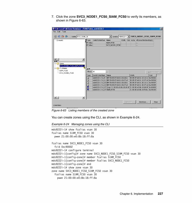
7. Click the zone SVC3_NODE1_FCS0_SIAM_FCS0 to verify its members, as shown in Figure 6-63.
Figure 6-63 Listing members of the created zone
You can create zones using the CLI, as shown in Example 6-24.
Example 6-24 Managing zones using the CLI
mds9222i-1# show fcalias vsan 30fcalias name SIAM_FCS0 vsan 30 pwwn 21:00:00:e0:8b:18:ff:8a
fcalias name SVC3_NODE1_FCS0 vsan 30 fcid 0xc90002mds9222i-1# configure terminalmds9222i-1(config)# zone name SVC3_NODE1_FCS0_SIAM_FCS0 vsan 30mds9222i-1(config-zone)# member fcalias SIAM_FCS0mds9222i-1(config-zone)# member fcalias SVC3_NODE1_FCS0mds9222i-1(config-zone)# endmds9222i-1# show zone vsan 30zone name SVC3_NODE1_FCS0_SIAM_FCS0 vsan 30 fcalias name SIAM_FCS0 vsan 30 pwwn 21:00:00:e0:8b:18:ff:8a
Chapter 6. Implementation 227

fcalias name SVC3_NODE1_FCS0 vsan 30 fcid 0xc90002
ZonesetWhereas a zone is used to specify access control, confining the specified members in a zone, zonesets are used to group zones and to enforce the access control defined by each zone when the zoneset is activated.
To create a zoneset, specify the name, VSAN, and members of the zoneset. In the following example we go through the steps to create the zoneset ZonesetActive3 in VSAN 30 and add the zone SVC3_NODE1_FCS0_SIAM_FCS0.
1. Right-click Zonesets and select Insert to create a new zoneset, as shown in Figure 6-64.
Figure 6-64 Define a new zoneset
228 Implementing an IBM/Cisco SAN

2. Define the name for the new zoneset and click OK, as shown in Figure 6-65.
Figure 6-65 Name the zoneset
At the next step, right-click the newly created zoneset ZonesetActive3 and select Insert to define members for the zoneset, as shown in Figure 6-66.
Figure 6-66 Insert zone members for a zoneset
Chapter 6. Implementation 229
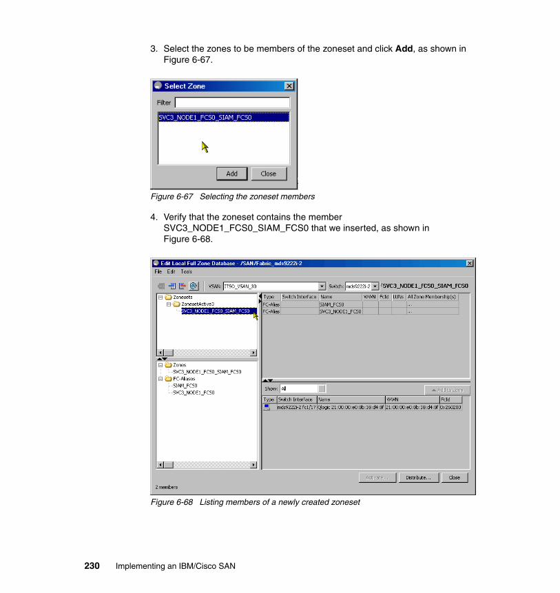
3. Select the zones to be members of the zoneset and click Add, as shown in Figure 6-67.
Figure 6-67 Selecting the zoneset members
4. Verify that the zoneset contains the member SVC3_NODE1_FCS0_SIAM_FCS0 that we inserted, as shown in Figure 6-68.
Figure 6-68 Listing members of a newly created zoneset
230 Implementing an IBM/Cisco SAN

5. In order to activate a zoneset right-click the zoneset ZonesetActive3, as shown in Figure 6-69.
Figure 6-69 Activate the zoneset
6. When prompted to save the running configuration to the startup configuration, and alternatively to a config file, click Continue Activation to activate the configuration, as shown in Figure 6-70.
Figure 6-70 Zoneset activation
Chapter 6. Implementation 231

7. Monitor the status of the activation (and save to the startup configuration) in the Zone Log window, as shown in Figure 6-71.
Figure 6-71 Monitoring status for the zoneset activation
You can create and configure zonesets using the CLI, as shown in Example 6-25.
Example 6-25 Managing zonesets using the CLI
mds9222i-1# show zone vsan 30zone name SVC3_NODE1_FCS0_SIAM_FCS0 vsan 30 fcalias name SIAM_FCS0 vsan 30 pwwn 21:00:00:e0:8b:18:ff:8a
fcalias name SVC3_NODE1_FCS0 vsan 30 fcid 0xc90002mds9222i-1# configure terminalmds9222i-1(config)# zoneset name ZonesetActive3 vsan 30mds9222i-1(config-zoneset)# member SVC3_NODE1_FCS0_SIAM_FCS0mds9222i-1(config-zoneset)# exitmds9222i-1(config)# zoneset activate name ZonesetActive3 vsan 30Zoneset activation initiated. check zone statusmds9222i-1(config)# exitmds9222i-1# show zoneset active vsan 30zoneset name ZonesetActive3 vsan 30 zone name SVC3_NODE1_FCS0_SIAM_FCS0 vsan 30 * fcid 0xc90100 [pwwn 21:00:00:e0:8b:18:ff:8a] * fcid 0xc90002
232 Implementing an IBM/Cisco SAN

Working with zonesetsWhen performing changes to the active zoneset, you work on a copy of the active zoneset in the full zoneset database. This means that any change does not take effect until you reactivate the zoneset, since the active zoneset cannot be altered while active.
To illustrate this, add a zone SVC1_NODE2_FCS0_NILE_FCS0 to the zoneset ZonesetActive1, show that it does not apply to the activated zoneset, and after that reactivate the zoneset ZonesetActive1.
As shown in Example 6-26, perform the following actions:
1. List zonesets for VSAN 10.2. List the active zoneset for VSAN 10.3. Add zone name SVC1_NODE2_FCS0_NILE_FCS0.4. Add the zone SVC1_NODE2_FCS0_NILE_FCS0 to ActiveZoneset1.5. List zonesets for VSAN 10.6. List the active zoneset.7. Reactivate the active zoneset.8. Verify that SVC1_NODE2_FCS0_NILE_FCS0 is part of the active zoneset.
Example 6-26 Performing changes to the active zoneset
1.
mds9222i-1# show zoneset vsan 10zoneset name ActiveZoneset1 vsan 10 zone name SVC1_NODE1_FCS0_NILE_FCS0 vsan 10 fcalias name SVC1_NODE1_FCS0 vsan 10 pwwn 50:05:07:68:01:10:37:e5
fcalias name NILE_FCS0 vsan 10 pwwn 21:00:00:e0:8b:89:2b:cd
2.
mds9222i-1# show zoneset active vsan 10zoneset name ActiveZoneset1 vsan 10 zone name SVC1_NODE1_FCS0_NILE_FCS0 vsan 10 * fcid 0x0b000a [pwwn 50:05:07:68:01:10:37:e5] * fcid 0x0b0100 [pwwn 21:00:00:e0:8b:89:2b:cd]
3.
mds9222i-1# configure terminalmds9222i-1(config)# zone name SVC1_NODE2_FCS0_NILE_FCS0 vsan 10mds9222i-1(config-zone)# member fcalias NILE_FCS0mds9222i-1(config-zone)# member fcalias SVC1_NODE2_FCS0Alias not presentmds9222i-1(config-zone)# exit
Chapter 6. Implementation 233

mds9222i-1(config)# fcalias name SVC1_NODE2_FCS0 vsan 10mds9222i-1(config-fcalias)# member pwwn 50:05:07:68:01:10:37:dcmds9222i-1(config-fcalias)# exitmds9222i-1(config)# zone name SVC1_NODE2_FCS0_NILE_FCS0 vsan 10mds9222i-1(config-zone)# member fcalias SVC1_NODE2_FCS0mds9222i-1(config-zone)# end
4.
mds9222i-1# configure terminalmds9222i-1(config)# zoneset name ZonesetActive1 vsan 10mds9222i-1(config-zoneset)# member SVC1_NODE2_FCS0_NILE_FCS0mds9222i-1(config-zoneset)# end
5.
mds9222i-1# show zoneset vsan 10zoneset name ZonesetActive1 vsan 10 zone name SVC1_NODE1_FCS0_NILE_FCS0 vsan 10 fcalias name SVC1_NODE1_FCS0 vsan 10 pwwn 50:05:07:68:01:10:37:e5
fcalias name NILE_FCS0 vsan 10 pwwn 21:00:00:e0:8b:89:2b:cd
zone name SVC1_NODE2_FCS0_NILE_FCS0 vsan 10 fcalias name NILE_FCS0 vsan 10 pwwn 21:00:00:e0:8b:89:2b:cd
fcalias name SVC1_NODE2_FCS0 vsan 10 pwwn 50:05:07:68:01:10:37:dc
6.
mds9222i-1# show zoneset active vsan 10zoneset name ActiveZoneset1 vsan 10 zone name SVC1_NODE1_FCS0_NILE_FCS0 vsan 10 * fcid 0x0b000a [pwwn 50:05:07:68:01:10:37:e5] * fcid 0x0b0100 [pwwn 21:00:00:e0:8b:89:2b:cd]
7.
mds9222i-1# configure terminalmds9222i-1(config)# zoneset activate name ZonesetActive1 vsan 10Zoneset activation initiated. check zone statusmds9222i-1(config)# end
8.
mds9222i-1# show zoneset active vsan 10zoneset name ZonesetActive1 vsan 10 zone name SVC1_NODE1_FCS0_NILE_FCS0 vsan 10 * fcid 0x0b000a [pwwn 50:05:07:68:01:10:37:e5] * fcid 0x0b0100 [pwwn 21:00:00:e0:8b:89:2b:cd]
234 Implementing an IBM/Cisco SAN

zone name SVC1_NODE2_FCS0_NILE_FCS0 vsan 10 * fcid 0x0b0100 [pwwn 21:00:00:e0:8b:89:2b:cd] * fcid 0x0b0008 [pwwn 50:05:07:68:01:10:37:dc]
When comparing step 5 with step 7, notice that the newly created zone has become a part of the active zoneset due to the reactivation of ZonesetActive1 in step 7.
Working with zonesets using the GUIWhen working with zonesets using the GUI, the same conditions apply, in that changes only take effect after you activate or reactivate the zoneset.
In Figure 6-72 a new zone has been dragged and dropped into the zoneset.
Figure 6-72 Dragging and dropping a new zone into the zoneset
Chapter 6. Implementation 235

In Figure 6-73 a modified zoneset will be reactivated.
Figure 6-73 Reactivating the zoneset
Fabric Manager will prompt you to review the changes that have been implemented, as shown in Figure 6-74 and Figure 6-75.
Figure 6-74 Review changes before reactivating zoneset
Figure 6-75 Review changes made in zoneset before reactivation
236 Implementing an IBM/Cisco SAN

In Figure 6-76 we save changes to a startup configuration to keep changes after a switch reboot.
Figure 6-76 Saving changes to the startup configuration
Verify the zoneset after reactivation and saving the configuration, as shown in Figure 6-77.
Figure 6-77 Verifying a zoneset configuration after changes
Zone distributionWhile all Cisco MDS 9000 family switches distribute the active zonesets when new E_Port links (ISL) appear, or when a new zone is activated in a VSAN, the full zoneset is not distributed automatically.
Chapter 6. Implementation 237

Distributing the full zoneset can be done either in Config or in EXEC mode.
Config modeThe zoneset distribute VSAN command in config mode is used on a per-VSAN basis to distribute the specified VSANs to all switches along with the active zoneset.
To configure distribution of the full zoneset database of a VSAN along with the active zoneset, use the config command zoneset distribute full, as shown in Example 6-27.
Example 6-27 Config command zoneset distribute full
mds9222i-1# config terminalEnter configuration commands, one per line. End with CNTL/Z.mds9222i-1(config)# zoneset distribute full vsan 10
EXEC modeThe zoneset distribute VSAN command in config mode is used to perform a one-time distribution of all inactive, unmodified zonesets to all switches in the fabric.
To distribute the full zoneset database of a VSAN, use the command zoneset distribute. As shown in Example 6-28, the full zoneset for VSAN 10 has been distributed, and this is verified using the command show zone status, as shown in Example 6-28.
Example 6-28 Distributing the full zoneset database for a VSAN
mds9222i-1# zoneset distribute vsan 10Zoneset distribution initiated. check zone statusmds9222i-1# show zone status vsan 10VSAN: 10 default-zone: permit distribute: full Interop: default mode: basic merge-control: allow session: none hard-zoning: enabled broadcast: disabledDefault zone: qos: none broadcast: disabled ronly: disabledFull Zoning Database : DB size: 484 bytes Zonesets:1 Zones:2 Aliases: 3Active Zoning Database : DB size: 152 bytes Name: ZonesetActive1 Zonesets:1 Zones:3Status: Zoneset distribution completed at 00:53:46 UTC Sep 19 2008
238 Implementing an IBM/Cisco SAN

To distribute the full zoneset database using the GUI, click Distribute, as shown in Figure 6-78.
Figure 6-78 Distributing the full zoneset database
Fabric Manager will prompt us to confirm zoneset distribution since this will overwrite the current full zone configuration on all switches in VSAN 30, as shown in Figure 6-79.
Figure 6-79 Confirm distribution of full zoneset database
Chapter 6. Implementation 239

Verification that the zoneset distribution has completed is shown in Figure 6-80 in the lower left corner.
Figure 6-80 Verifying the status of the zoneset distribution
6.1.11 LUN zoningThe LUN zoning feature, at the time of writing, is specific for the Cisco MDS family, and is not available in interop mode. Since most storage devices used in today’s production environments provide LUN masking, this feature is not extensively used, although it is available and can even be combined with LUN masking at the storage subsystem.
For details on how to configure LUN masking, consult the MDS Cisco Configuration Guide:
http://www.cisco.com/en/US/products/ps5989/products_installation_and_configuration_guides_list.html
Note: When removing only a few zones from a zoneset, the full zoneset database for the VSAN is only distributed across the fabric and is not saved to the startup configuration on the other switches (regardless of whether you use the CLI or GUI). Therefore, you subsequently must perform this task on the other switches in the fabric.
240 Implementing an IBM/Cisco SAN

6.2 Multiple switch environment
In the topics that follow, we show how to configure an Inter-Switch Link.
6.2.1 Inter-switch link
An Inter-Switch Link (ISL) is created when connecting an E_Port (expansion port) of one switch to an E_Port on another switch. When multiple ISLs are used, these can be congregated to become a single logical ISL, which, in Cisco terminology, is called a PortChannel.
Prior to establishing an ISL between two switches, we launch the merge analysis tool to verify that our existing VSANs can merge successfully across the fabric to avoid segmentation. In Figure 6-81 click Zone and select Merge Analysis to launch the tool.
Figure 6-81 Launching the merge analysis tool
Chapter 6. Implementation 241
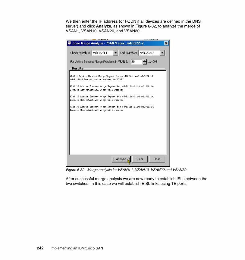
We then enter the IP address (or FQDN if all devices are defined in the DNS server) and click Analyze, as shown in Figure 6-82, to analyze the merge of VSAN1, VSAN10, VSAN20, and VSAN30.
Figure 6-82 Merge analysis for VSAN’s 1, VSAN10, VSAN20 and VSAN30
After successful merge analysis we are now ready to establish ISLs between the two switches. In this case we will establish EISL links using TE ports.
242 Implementing an IBM/Cisco SAN

We will connect two switches using two ISLs, as shown in Figure 6-83 and Figure 6-84. Depending on the trunk setting for the port, it becomes either an E_Port or a TE_Port. In our example, both ports are TE_Ports.
Figure 6-83 ISL connections, TE_Ports on MDS9222i-1 switch
Figure 6-84 ISL connections, TE_Ports on MDS9222i-2 switch
Chapter 6. Implementation 243

After connecting the two switches, Fabric Manager shows the added switch and ISLs in the graphical presentation of the fabric, as shown in Figure 6-85.
Figure 6-85 Fabric expanded by adding a switch
6.2.2 Trunking and PortChannel
In Cisco terminology, the term trunking is used to describe a single trunking E_Port (TE_Port) that can multiplex the traffic of more than one VSAN on a single physical interface. This is in contrast to other Fibre Channel switch manufacturers that use the term trunking to describe the aggregation of several physical interfaces into a single logical interface. Cisco calls this latter feature PortChannel.
Trunking and PortChannel features are available for both Fibre Channel and gigabit Ethernet interfaces on the Cisco MDS 9000 family. Since the configuration rules for these features are different, we describe both of them separately.
244 Implementing an IBM/Cisco SAN

6.2.3 FC trunking
Trunking (also known as VSAN trunking) enables interconnect ports to transmit and receive frames in more than one VSAN over the same physical link. In this case the link is configured as an extended ISL (EISL) link using the EISL frame format.
Trunking is only applicable to E_Ports and used for inter-switch connections. Trunking is normally enabled for all ports in the switch but can be disabled on a port-by-port basis. If the port becomes operational as a trunking E_Port, it is referred to as a TE_Port. If a port with trunking enabled is connected to a third-party switch, it works as a normal E_Port.
6.2.4 FC PortChannel
The PortChannel feature can be used to aggregate up to 16 ISL or EISL links into a single logical link. The Fibre Channel ports can be any Fibre Channel ports in any 16-port Fibre Channel line card.
The PortChannel feature increases the available aggregate bandwidth of the logical link since the traffic is distributed among all functional links in the channel. It also provides high availability, since the channel remains active as long as at least one of the links forming it remains active, and the traffic is transparently distributed over the remaining links.
Since PortChannel can be built on EISL links, both trunking and PortChannel are supported simultaneously.
Defining a PortChannel using the CLI In our setup we have the EISLs listed in Table 6-1.
Table 6-1 EISLs in our LAB setup
MDS9222i-1 MDS9222i-2 Link speed Trunk
fc2/1 fc2/1 8 Gbps On
fc2/25 fc2/25 8 Gbps On
Chapter 6. Implementation 245

In Example 6-29 we define PortChannel 10 to include all (two) EISLs between the switches mds92222i-1 and mds9222i-2, which takes the EISL ports down. When performing the no shutdown command, the ports come back up and the PortChannel will be established. Finally, we will list the PortChannel database on each switch, using the command show port-channel database.
Example 6-29 Setting up PortChannel
mds9222i-1# show topologyFC Topology for VSAN 1 :------------------------------------------------------------------------------- Interface Peer Domain Peer Interface Peer IP Address------------------------------------------------------------------------------- fc2/1 0xa1(161) fc2/1 9.43.86.148 fc2/25 0xa1(161) fc2/25 9.43.86.148
FC Topology for VSAN 10 :------------------------------------------------------------------------------- Interface Peer Domain Peer Interface Peer IP Address------------------------------------------------------------------------------- fc2/1 0x0c(12) fc2/1 9.43.86.148 fc2/25 0x0c(12) fc2/25 9.43.86.148
FC Topology for VSAN 20 :------------------------------------------------------------------------------- Interface Peer Domain Peer Interface Peer IP Address------------------------------------------------------------------------------- fc2/1 0x19(25) fc2/1 9.43.86.148 fc2/25 0x19(25) fc2/25 9.43.86.148
FC Topology for VSAN 30 :------------------------------------------------------------------------------- Interface Peer Domain Peer Interface Peer IP Address------------------------------------------------------------------------------- fc2/1 0x26(38) fc2/1 9.43.86.148 fc2/25 0x26(38) fc2/25 9.43.86.148
mds9222i-1# configure terminalmds9222i-1(config)# interface fc 2/1, fc 2/25mds9222i-1(config-if)# channel-group 10fc2/1 fc2/25 added to port-channel 10 and disabledplease do the same operation on the switch at the other end of the port-channel, then do "no shutdown" at both end to bring them up
mds9222i-2# configure terminalmds9222i-2(config)# interface fc 2/1, fc 2/25mds9222i-2(config-if)# channel-group 10fc2/1 fc2/25 added to port-channel 10 and disabled
246 Implementing an IBM/Cisco SAN

please do the same operation on the switch at the other end of the port-channel,then do "no shutdown" at both end to bring them up
mds9222i-2(config-if)# no shutdown
mds9222i-1(config-if)# no shutdown
mds9222i-1# show port-channel databaseport-channel 10 Administrative channel mode is on Operational channel mode is on Last membership update succeeded First operational port is fc2/25 2 ports in total, 2 ports up Ports: fc2/1 [up] fc2/25 [up] *
mds9222i-2# show port-channel databaseport-channel 10 Administrative channel mode is on Operational channel mode is on Last membership update succeeded First operational port is fc2/25 2 ports in total, 2 ports up Ports: fc2/1 [up] fc2/25 [up] *mds9222i-2# show topology
FC Topology for VSAN 10 :------------------------------------------------------------------------------- Interface Peer Domain Peer Interface Peer IP Address------------------------------------------------------------------------------- port-channel 10 0x0b(11) port-channel 10 9.43.86.147
FC Topology for VSAN 20 :------------------------------------------------------------------------------- Interface Peer Domain Peer Interface Peer IP Address------------------------------------------------------------------------------- port-channel 10 0x9c(156) port-channel 10 9.43.86.147
FC Topology for VSAN 30 :------------------------------------------------------------------------------- Interface Peer Domain Peer Interface Peer IP Address------------------------------------------------------------------------------- port-channel 10 0xc9(201) port-channel 10 9.43.86.147
Chapter 6. Implementation 247

Defining a PortChannel using the GUI Now we configure a PortChannel group using the GUI. As the first step we need to verify that we have EISLs between our switches mds92222i-1 and mds9222i-2.
1. To start the PortChannel configuration from the GUI, select the icon, as shown in Figure 6-86.
Figure 6-86 Two MDS9222i connected by two EISL 8 Gbps links
Note: When creating a PortChannel, a compatibility check is performed to ensure that all configuration parameters for each physical port in the channel are the same. Therefore, a port cannot become operational if incompatibility issues exist. For example, to enable trunk mode, all ports must be configured with trunk mode enabled prior to creating the PortChannel.
Tip: Using the force option when adding a port to a PortChannel forces the configuration of the ports in the PortChannel onto the added port to achieve compatibility.
248 Implementing an IBM/Cisco SAN

2. Select switch pair to establish a PortChannel and select Create New, as shown in Figure 6-87.
Figure 6-87 Select switch pair to establish a PortChannel
Chapter 6. Implementation 249

3. Choose the ports to form a PortChannel, as shown in Figure 6-88.
Figure 6-88 Select ports to form a PortChannel
250 Implementing an IBM/Cisco SAN

4. In the final step for both switches we must define all the required parameters to set up a PortChannel, as shown in Figure 6-89:
– Channel ID number for both switches: We recommend using the same ID for both switches to simplify administration.
– VSAN List gives a list of VSANs to which the ISLs belong.
– Port VSAN for a PortChannel: Logical assignment of the PortChannel to a particular VSAN. There are no functional implications.
– The aggregated speed of the PortChannel.
– Trunk Mode to enable trunking on the links in the PortChannel. Select trunking if your link is between TE_ports. Select non-trunking if your link is between E_ports. Select auto if you are not sure.
– Force Admin, Trunk, Speed, and VSAN attributes to be identical: This check box ensures that the same parameter settings are used in all physical ports in the channel. If these settings are not identical, the ports cannot become part of the PortChannel.
Figure 6-89 Final step to configure a PortChannel using the GUI
Chapter 6. Implementation 251

5. In our example we use 8 Gbps TE ports to set up a PortChannel between two MDS9222i switches.
Fabric Manager will warn us that the process of converting ports into a PortChannel may be disruptive, as shown in Figure 6-90.
Figure 6-90 Converting ports into a PortChannel may be disruptive message
Verify the PortChannel configuration and the status of the connection, as shown in Figure 6-91.
Figure 6-91 PortChannel status in GUI
252 Implementing an IBM/Cisco SAN

6.3 Inter VSAN Routing (IVR)
VSANs provide the benefit of sharing the physical switch infrastructure while isolating traffic between VSANs. This inherently prevents resource sharing between VSANs. Using IVR provides resource sharing across VSANs without compromising the benefits of VSANs. IVR is done by specifying initiators and devices in different VSANs without merging the respective VSANs together.
To understand how IVR works, we first clarify the following IVR definitions:
� Inter VSAN Zone (IVZ): A set of end devices that are allowed to communicate across VSANs within their interconnected SAN fabric. This definition is based on their port World Wide Names (pWWNs) and their native VSAN associations. You can configure up to 200 IVZs and 2,000 IVZ members on any switch in the Cisco MDS 9000 family.
� Inter VSAN zonesets (IVZS): One or more IVZs make up an IVZS. You can configure up to 32 IVZSs on any switch in the Cisco MDS 9000 family. Only one IVZS can be active at any time.
� Inter VSAN Path (IVR Path): An IVR path is a set of switches and Inter-Switch Links through which a frame from one end device in one VSAN can reach another end device in some other VSAN. Multiple paths can exist between two such end devices.
� Edge and Transit VSANs: A VSAN that initiates (source edge-VSAN) or terminates (destination edge-VSAN) an IVR path. Edge VSANs might be adjacent to each other or they might be connected by one or more transit VSANs.
Some guidelines to follow before IVR creation are:
� Verify that unique domain IDs are configured in all switches and VSANs participating in IVR.
� Enable IVR in the border switches.
Note: The Enterprise License Package (ENTERPRISE_PKG) must be installed on all IVR edge or transit switches.
Note: Unique domain IDs are not a requirement when using IVR-NAT. A common domain ID (10, for example) could be in VSAN 5 and VSAN 6 and you could still route between devices in these VSANs attached to the switches with domain ID 10.
Chapter 6. Implementation 253

� Configure the required IVR topology in all the IVR-enabled border switches, or use the recommended auto-topology feature, which eliminates the necessity for the user to define one.
� Create and activate IVZSs in all the IVR-enabled border switches.
� Verify the IVR configuration.
6.3.1 Configuring IVR using the GUI
We now demonstrate a simple IVR to allow selected members of different VSANs to communicate.
The first step is to locate the IVR Wizard. This is the same wizard that we use for normal zoning operations, and is found by starting with the Fabric Manager IVR Wizard icon, as seen in Figure 6-92.
Figure 6-92 Starting the IVR wizard
As we want to use IVR NAT, we select the IVR NAT option, as shown in Figure 6-93.
Figure 6-93 Selecting IVR NAT
254 Implementing an IBM/Cisco SAN

In Figure 6-94 we select the fabric.
Figure 6-94 Select fabric to set up IVR
We continue setting up our IVR by proceeding to the next panel, where we have to move the VSANs that we are working with to the appropriate window, as seen in Figure 6-95.
Figure 6-95 Selecting VSANs
Chapter 6. Implementation 255

We proceed to the next panel, as shown in Figure 6-96.
Figure 6-96 Selecting end devices
256 Implementing an IBM/Cisco SAN

After selecting the IVR NAT participants, we add them to the Selected window, as seen in Figure 6-97.
Figure 6-97 Selecting IVR switches
Note: Cisco MDS SAN-OS Release 2.1(1a) introduced IVR NAT, which allows you to set up IVR in a fabric without requiring unique domain IDs on every switch in the IVR path. When IVR NAT is enabled, the virtualized end device that appears in the native VSAN uses a virtual domain ID that is unique to the native VSAN.
Chapter 6. Implementation 257

Now we must specify a zone name, as shown in Figure 6-98.
Figure 6-98 Selecting a zone name
Now we can review our actions and the progress, as seen in Figure 6-99.
Figure 6-99 Review our actions
258 Implementing an IBM/Cisco SAN
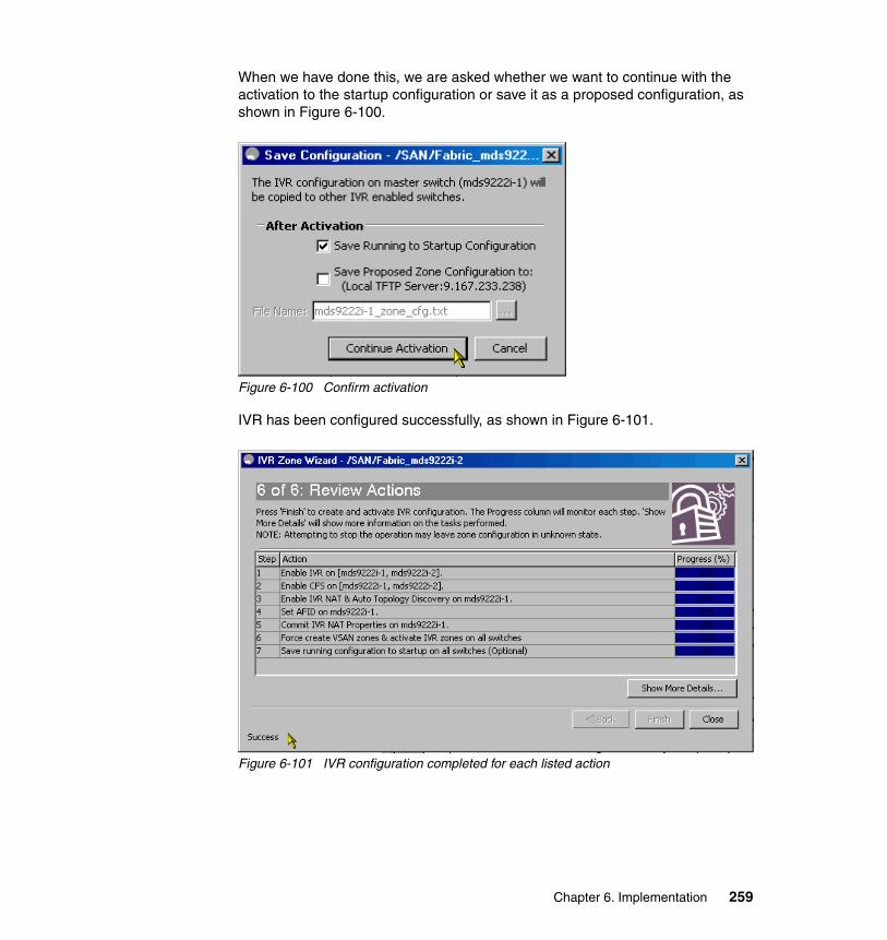
When we have done this, we are asked whether we want to continue with the activation to the startup configuration or save it as a proposed configuration, as shown in Figure 6-100.
Figure 6-100 Confirm activation
IVR has been configured successfully, as shown in Figure 6-101.
Figure 6-101 IVR configuration completed for each listed action
Chapter 6. Implementation 259

You can check the status of IVR using the CLI, as shown in Example 6-30.
Example 6-30 IVR status using the CLI
mds9222i-1# show ivr zonesetzoneset name IVR_Zoneset1 zone name IvrZone1 pwwn 50:05:07:68:01:10:37:e5 vsan 10 autonomous-fabric-id 1 pwwn 50:05:07:68:01:10:37:dc vsan 10 autonomous-fabric-id 1 pwwn 21:00:00:e0:8b:18:ff:8a vsan 30 autonomous-fabric-id 1
mds9222i-1# show ivr session statusLast Action Time Stamp : Fri Sep 19 03:26:41 2008Last Action : CommitLast Action Result : SuccessLast Action Failure Reason : none
mds9222i-1# show ivr virtual-domains vsan 10VSAN # Domains IVR Virtual Domains---- --------- ---------------------------------------------- 10 1 75---- --------- ----------------------------------------------
mds9222i-1# show ivr virtual-domains vsan 30VSAN # Domains IVR Virtual Domains---- --------- ---------------------------------------------- 30 1 121---- --------- ----------------------------------------------
mds9222i-1# show ivr vsan-topology
AFID SWITCH WWN Active Cfg. VSANS Switch-Name------------------------------------------------------------------------- 1 20:00:00:0d:ec:4a:c5:80 yes no 1,10,20,30 1 20:00:00:0d:ec:82:3d:00 * yes no 1,10,20,30
Total: 2 entries in active and configured IVR VSAN-Topology
260 Implementing an IBM/Cisco SAN

6.3.2 Configuring IVR using the CLI
All IVR configuration steps can also be performed using the CLI. Example 6-31 shows how to manage the IVR zone and zone set configuration.
Example 6-31 IVR zone and zoneset configuration from the CLI
mds9222i-2# show flogi database-----------------------------------------------------------------------INTERFACE VSAN FCID PORT NAME NODE NAME-----------------------------------------------------------------------fc1/5 20 0x15000e 50:05:07:68:01:20:1d:22 50:05:07:68:01:00:1d:22fc1/6 20 0x150003 50:05:07:68:01:40:1d:22 50:05:07:68:01:00:1d:22fc1/7 20 0x150000 50:05:07:68:01:20:1d:21 50:05:07:68:01:00:1d:21fc1/8 20 0x150001 50:05:07:68:01:40:1d:21 50:05:07:68:01:00:1d:21fc1/9 30 0x1f0006 50:05:07:68:01:20:1d:1c 50:05:07:68:01:00:1d:1cfc1/10 30 0x1f000a 50:05:07:68:01:40:1d:1c 50:05:07:68:01:00:1d:1cfc1/11 30 0x1f0001 50:05:07:68:01:20:27:e2 50:05:07:68:01:00:27:e2fc1/14 20 0x150100 21:00:00:e0:8b:89:b8:c0 20:00:00:e0:8b:89:b8:c0fc1/15 50 0x6e0000 21:00:00:e0:8b:05:41:bc 20:00:00:e0:8b:05:41:bc [Diomede_1]fc1/16 20 0x150200 21:00:00:e0:8b:89:c1:cd 20:00:00:e0:8b:89:c1:cdfc1/17 10 0x0b0100 21:00:00:e0:8b:18:d4:8f 20:00:00:e0:8b:18:d4:8ffc2/2 20 0x150300 20:05:00:a0:b8:17:44:33 20:04:00:a0:b8:17:44:31
Total number of flogi = 12.
mds9222i-1# show flogi database-----------------------------------------------------------------------INTERFACE VSAN FCID PORT NAME NODE NAME-----------------------------------------------------------------------fc1/1 20 0x14000a 50:05:07:68:01:10:37:e5 50:05:07:68:01:00:37:e5fc1/2 20 0x14000b 50:05:07:68:01:30:37:e5 50:05:07:68:01:00:37:e5fc1/3 20 0x140008 50:05:07:68:01:10:37:dc 50:05:07:68:01:00:37:dcfc1/4 20 0x140009 50:05:07:68:01:30:37:dc 50:05:07:68:01:00:37:dcfc1/14 30 0x1e0100 21:00:00:e0:8b:89:2b:cd 20:00:00:e0:8b:89:2b:cd [Nile_1]fc1/15 20 0x140400 21:00:00:e0:8b:05:48:bc 20:00:00:e0:8b:05:48:bcfc1/16 20 0x140200 21:00:00:e0:8b:05:4c:aa 20:00:00:e0:8b:05:4c:aa [Palau_1]fc1/17 50 0x640000 21:00:00:e0:8b:18:ff:8a 20:00:00:e0:8b:18:ff:8afc2/2 20 0x140300 20:04:00:a0:b8:17:44:32 20:04:00:a0:b8:17:44:31fc2/17 20 0x140000 50:03:08:c1:40:46:70:06 50:03:08:c1:40:06:70:06
Total number of flogi = 10.
mds9222i-2# configure terminalmds9222i-2(config)# ivr zone name IVR_SVC_Diomedemds9222i-2(config-ivr-zone)# member pwwn 21:00:00:e0:8b:05:41:bc vsan 50mds9222i-2(config-ivr-zone)# member pwwn 50:05:07:68:01:10:37:e5 vsan 20mds9222i-2(config-ivr-zone)# member pwwn 50:05:07:68:01:30:37:e5 vsan 20mds9222i-2(config-ivr-zone)# member pwwn 50:05:07:68:01:10:37:dc vsan 20
Chapter 6. Implementation 261

mds9222i-2(config-ivr-zone)# member pwwn 50:05:07:68:01:30:37:dc vsan 20mds9222i-2(config-ivr-zone)# exitmds9222i-2(config)# ivr zoneset name IVR_Zoneset_SVCmds9222i-2(config-ivr-zoneset)# member IVR_SVC_Diomedemds9222i-2(config-ivr-zoneset)# exitmds9222i-2(config)# ivr distributemds9222i-2(config)# ivr commitcommit initiated. check ivr statusmds9222i-2(config)# endmds9222i-2# show ivr zoneset
zoneset name IVR_Zoneset_SVC zone name IvrZone_SIAM_SVC_1 pwwn 21:00:00:e0:8b:18:ff:8a vsan 50 autonomous-fabric-id 1 pwwn 50:05:07:68:01:10:37:e5 vsan 20 autonomous-fabric-id 1 pwwn 50:05:07:68:01:30:37:e5 vsan 20 autonomous-fabric-id 1 pwwn 50:05:07:68:01:30:37:dc vsan 20 autonomous-fabric-id 1 pwwn 50:05:07:68:01:10:37:dc vsan 20 autonomous-fabric-id 1
zone name IVR_SVC_Diamonde pwwn 21:00:00:e0:8b:05:41:bc vsan 50 autonomous-fabric-id 1 [Diomede_1] pwwn 50:05:07:68:01:10:37:e5 vsan 20 autonomous-fabric-id 1 pwwn 50:05:07:68:01:30:37:e5 vsan 20 autonomous-fabric-id 1 pwwn 50:05:07:68:01:10:37:dc vsan 20 autonomous-fabric-id 1 pwwn 50:05:07:68:01:30:37:dc vsan 20 autonomous-fabric-id 1
mds9222i-2# show ivr zoneset active
zoneset name IVR_Zoneset_SVC zone name IvrZone_SIAM_SVC_1 * pwwn 21:00:00:e0:8b:18:ff:8a vsan 50 autonomous-fabric-id 1 * pwwn 50:05:07:68:01:10:37:e5 vsan 20 autonomous-fabric-id 1 * pwwn 50:05:07:68:01:30:37:e5 vsan 20 autonomous-fabric-id 1 * pwwn 50:05:07:68:01:30:37:dc vsan 20 autonomous-fabric-id 1 * pwwn 50:05:07:68:01:10:37:dc vsan 20 autonomous-fabric-id 1
zone name IVR_SVC_Diomede * pwwn 21:00:00:e0:8b:05:41:bc vsan 50 autonomous-fabric-id 1 [Diomede_1] * pwwn 50:05:07:68:01:30:37:e5 vsan 20 autonomous-fabric-id 1 * pwwn 50:05:07:68:01:30:37:dc vsan 20 autonomous-fabric-id 1 * pwwn 50:05:07:68:01:10:37:dc vsan 20 autonomous-fabric-id 1 * pwwn 50:05:07:68:01:10:37:e5 vsan 20 autonomous-fabric-id 1
262 Implementing an IBM/Cisco SAN
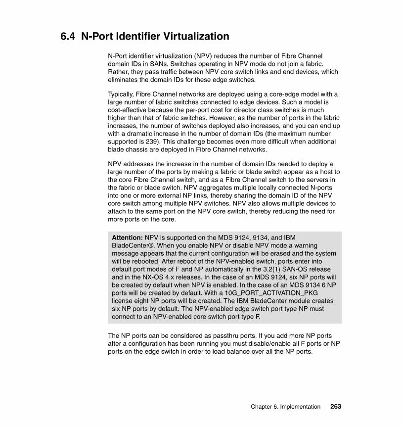
6.4 N-Port Identifier Virtualization
N-Port identifier virtualization (NPV) reduces the number of Fibre Channel domain IDs in SANs. Switches operating in NPV mode do not join a fabric. Rather, they pass traffic between NPV core switch links and end devices, which eliminates the domain IDs for these edge switches.
Typically, Fibre Channel networks are deployed using a core-edge model with a large number of fabric switches connected to edge devices. Such a model is cost-effective because the per-port cost for director class switches is much higher than that of fabric switches. However, as the number of ports in the fabric increases, the number of switches deployed also increases, and you can end up with a dramatic increase in the number of domain IDs (the maximum number supported is 239). This challenge becomes even more difficult when additional blade chassis are deployed in Fibre Channel networks.
NPV addresses the increase in the number of domain IDs needed to deploy a large number of the ports by making a fabric or blade switch appear as a host to the core Fibre Channel switch, and as a Fibre Channel switch to the servers in the fabric or blade switch. NPV aggregates multiple locally connected N-ports into one or more external NP links, thereby sharing the domain ID of the NPV core switch among multiple NPV switches. NPV also allows multiple devices to attach to the same port on the NPV core switch, thereby reducing the need for more ports on the core.
The NP ports can be considered as passthru ports. If you add more NP ports after a configuration has been running you must disable/enable all F ports or NP ports on the edge switch in order to load balance over all the NP ports.
Attention: NPV is supported on the MDS 9124, 9134, and IBM BladeCenter®. When you enable NPV or disable NPV mode a warning message appears that the current configuration will be erased and the system will be rebooted. After reboot of the NPV-enabled switch, ports enter into default port modes of F and NP automatically in the 3.2(1) SAN-OS release and in the NX-OS 4.x releases. In the case of an MDS 9124, six NP ports will be created by default when NPV is enabled. In the case of an MDS 9134 6 NP ports will be created by default. With a 10G_PORT_ACTIVATION_PKG license eight NP ports will be created. The IBM BladeCenter module creates six NP ports by default. The NPV-enabled edge switch port type NP must connect to an NPV-enabled core switch port type F.
Chapter 6. Implementation 263

6.4.1 Configuring NPV on an edge switch and NPV on a core switch
Using Device Manager:
1. Launch Device Manager from the core NPV switch to enable NPV. From the Admin drop-down menu, select Feature Control. Select enable for the NPV feature.
2. Click Apply.
3. From the Interface drop-down menu, select FC All to configure the NPV core switch port as an F-Port.
4. In the Mode Admin column, select the F port mode and click Apply.
5. Launch Device Manager from the NPV edge switch to enable NPV. From the Admin drop-down menu, select Feature Control. Select enable for the NPV feature and click Apply.
6. From the Interface drop-down menu, select FC All to configure the external interfaces on the NPV device.
7. In the Mode Admin column, select the NP port mode and click Apply.
8. To configure the server interfaces on the NPV edge switch, from the Interface drop-down menu, select FC All.
9. In the Mode Admin column, select F port mode and click Apply.
10.The default admin status is down. After configuring port modes, you must select up admin status to bring up the links.
6.4.2 Enable or disable NPV via the CLI on supported edge switches
Using the CLI, at the prompt enter these commands:
1. Enter config t to get into config mode.2. Enter npv enable when in config mode.3. Enter no npv enable when in config mode.4. End config mode by entering the command end.
6.4.3 Enable or disable NPV via the CLI on supported core switches
Using the CLI, at the prompt enter these commands:
1. Enter config t to get into config mode.2. Enter npv enable when in config mode.3. Enter no npv enable when in config mode.4. End config mode by entering the command end.
264 Implementing an IBM/Cisco SAN

Note: NPV configuration is allowed only on NPV-capable MDS switches like MDS 9124, MDS 9134, and Blade Server switches with SAN-OS Version 3.2(2) or later. NPV is supported in NX-OS as well.
Chapter 6. Implementation 265

266 Implementing an IBM/Cisco SAN

Chapter 7. IP services
FCIP provides the capability to extend a SAN over existing IP networks. For short distances, SANs can be extended using traditional FC ISLs and multimode fiber. For longer distances, extend SANs using single-mode fiber with Coarse Wave Division Multiplexing (CWDM) or Dense Wave Division Multiplexing (DWDM) equipment. FCIP provides a third alternative for extending SANs over IP networks where IP is the most viable transport option, either due to cost or distance.
When implementing any MDS 9000 family IP services module (as well as the MDS 9216i and MDS 9222i), the traffic can be routed between any IP storage port and any other port on the MDS 9000 family switches in the fabric. It is configurable on a per-port basis, providing either Fibre Channel over IP (FCIP) or iSCSI on the defined port.
7
© Copyright IBM Corp. 2009. All rights reserved. 267

In this chapter we configure FCIP links from the MDS 9222i (9222i-1) to the MDS 9222i (9222i-2), as shown in Figure 7-1.
Figure 7-1 Implementation scenario
268 Implementing an IBM/Cisco SAN

7.1 FCIP licensing
Most Cisco MDS 9000 family software features are included in the base switch configuration. However, some features are logically grouped into add-on packages that must be licensed separately, such as the Cisco MDS 9000 Enterprise package, SAN Extension over IP package, Mainframe package, Fabric Manager Server package, and Storage Services Enabler package.
To enable FCIP in a MDS switch equipped with the IP module you need a SAN Extension over IP package license. This package is licensed on a per-module basis. The number of licenses is equal to the number of IP Storage Services and Multiprotocol Services modules in a switch.
The SAN Extension over IP (SAN_EXTN_OVER_IP) license for IPS modules includes:
� FCIP protocol� FCIP compression� FCIP write acceleration
The 9216i and 9222i are shipped with the required licences for FCIP. The included licence is SAN Extension over IP package for integrated IP ports and includes all of the protocols that are in the SAN_EXTN_OVER_IP licence.
The licenses are, however, needed on a per-module basis. For example, if you have two 18/4-port MSM modules running FCIP in a switch, you need two SAN_EXTN_OVER_IP licenses. If you added an 18/4-port MSM module to your MDS9216i or 9222i, you still need the SAN_EXTN_OVER_IP license for that module.
Note: For SAN-OS 2.0 and later, the SAN Extension licence also includes:
� IVR � Tape acceleration
Chapter 7. IP services 269
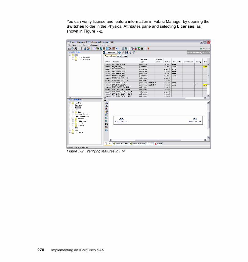
You can verify license and feature information in Fabric Manager by opening the Switches folder in the Physical Attributes pane and selecting Licenses, as shown in Figure 7-2.
Figure 7-2 Verifying features in FM
270 Implementing an IBM/Cisco SAN

Select the Keys tab to display the licence keys, as shown in Figure 7-3. Your display might look different, but still displays the switch licensed information.
Figure 7-3 LIcense keys in FM
7.2 FCIP concepts
To configure the IPS module for FCIP, you should have a basic understanding of the following concepts:
� FCIP and VE_Ports� FCIP links� FCIP profiles� FCIP interfaces
FCIP and VE_Ports describe the internal model of FCIP with respect to Fibre Channel Inter-Switch Links (ISLs) and Cisco's enhanced ISLs (EISLs).
Chapter 7. IP services 271

FCIP defines virtual E (VE) ports, which behave exactly like standard Fibre Channel E_Ports, except that the transport in this case is FCIP instead of Fibre Channel. The only requirement is for the other end of the VE_Port to be another VE_Port. A virtual ISL is established over an FCIP link and transports Fibre Channel traffic. Each associated virtual ISL looks like a Fibre Channel ISL with either an E_Port or a TE_Port at each end, as shown in Figure 7-4.
Figure 7-4 FCIP Links and Virtual ISLs
FCIP links consist of one or more TCP connections between two FCIP link end points. Each link carries encapsulated Fibre Channel frames. When the FCIP link comes up, the VE_Ports at both ends of the FCIP link create a virtual Fibre Channel (E)ISL and initiate the E_Port protocol to bring up the (E)ISL. By default, the FCIP feature on any Cisco MDS 9000 family switch creates two TCP connections for each FCIP link.
� One connection is used for data frames.
� The second connection is used only for Fibre Channel control frames, that is, switch-to-switch protocol frames (all Class F) frames. This arrangement is used to provide low latency for all control frames.
To enable FCIP on the IPS module, an FCIP profile and FCIP interface (interface FCIP) must be configured. The FCIP link is established between two peers. The VE_Port initialization behavior is identical to a normal E_Port. This behavior is independent of the link being FCIP or pure Fibre Channel, and is based on the E_Port discovery process (ELP, ESC). When the FCIP link is established, the VE_Port behavior is identical to E_Port behavior for all inter-switch communication (including domain management, zones, and VSANs). At the Fibre Channel layer, all VE and E_Port operations are identical.
272 Implementing an IBM/Cisco SAN

The FCIP profile contains information about local IP address and TCP parameters. The profile defines the following information:
� The local connection points (IP address and TCP port number)
� The behavior of the underlying TCP connections for all FCIP links that use this profile
The FCIP profile’s local IP address determines the Gigabit Ethernet port where the FCIP links terminate.
The FCIP interface is the local endpoint of the FCIP link and a VE_Port interface. All the FCIP and E_Port parameters are configured in context with the FCIP interface.
The FCIP profile determines which Gigabit Ethernet port initiates the FCIP links and defines the TCP connection behavior.
The FCIP parameters consist of the following data:
� Peer information� Number of TCP connections for the FCIP link� E_Port parameters: Trunking mode and trunk-allowed VSAN list
7.2.1 Configuring FCIP using the CLI
Setting up FCIP is a step-by-step process, and in the following sections we perform each of the following steps to set up FCIP using the CLI:
1. Enable FCIP.2. Configure the GigE interface.3. Create an FCIP profile and assign the GigE interface IP address.4. Create an FCIP interface and assign the FCIP profile.5. Configure the peer IP address for the FCIP interface.6. Enable the FCIP interface.
Chapter 7. IP services 273

Enable FCIPTo enable FCIP we use the command fcip enable, as shown in Example 7-1. If you do not have a license installed you will be informed that you are using a temporary license that is valid for 120 days from the first activation (this must be done on both switches).
Example 7-1 Enabling FCIP
mds9222i-1(config)# exitmds9222i-1# configure terminalmds9222i-1(config)# fcip enablemds9222i-1(config)#
Configure GigE interfaceIn Example 7-2 we assign an IP address (10.1.1.1/24) on switch 9222i-1 to the GigE interface GigabitEthernet1/1, and on switch 9222i-2 we assign an IP address (10.1.1.2/24) to the interface GigabitEthernet4/1.
Example 7-2 Configure the GigE interface
mds9222i-1# configure terminalEnter configuration commands, one per line. End with CNTL/Z.mds9222i-1(config)# interface gigabitethernet 1/1mds9222i-1(config-if)# ip address 10.1.1.1 255.255.255.0mds9222i-1(config-if)#
mds9222i-2# configure terminalEnter configuration commands, one per line. End with CNTL/Z.mds9222i-2(config)# interface gigabitethernet 1/1mds9222i-2(config-if)# ip address 10.1.1.2 255.255.255.0mds9222i-2(config-if)#
Note: Prior to setting up FCIP we must enable the FCIP feature on the switches, as it is disabled by default on all switches.
When enabling FCIP there is a check to see whether you have a current SAN_EXTN_OVER_IP license installed. The 9221i and 9216i will have this licence pre-installed for their integrated IP services module.
274 Implementing an IBM/Cisco SAN

Create FCIP profileNext we create the FCIP profile, as shown in Example 7-3.
Example 7-3 Create FCIP profile
mds9222i-1# configure terminalEnter configuration commands, one per line. End with CNTL/Z.mds9222i-1(config)# fcip profile 1mds9222i-1(config-profile)#ip address 10.1.1.1mds9222i-1(config-profile)# tcp max-bandwidth-mbps 1000 min-available-bandwidth-mbps 500 rouround-trip-time-ms 600mds9222i-1(config-profile)#
mds9222i-2# configure terminalEnter configuration commands, one per line. End with CNTL/Z.mds9222i-2(config)# fcip profile 1mds9222i-2(config-profile)#ip address 10.1.1.2mds9222i-2(config-profile)# tcp max-bandwidth-mbps 1000 min-available-bandwidth-mbps 500 rouround-trip-time-ms 600mds9222i-2(config-profile)#
Create FCIP interfaceIn Example 7-4 we create the FCIP interface.
Example 7-4 Create FCIP interface
mds9222i-1# config tEnter configuration commands, one per line. End with CNTL/Z.mds9222i-1(config)# interface fcip 2mds9222i-1(config-if)# use-profile 1mds9222i-1(config-if)# peer info address 10.1.1.2mds9222i-1(config-if)# no shutdown
mds9222i-2# config tEnter configuration commands, one per line. End with CNTL/Z.mds9222i-2(config)# interface fcip 2mds9222i-2(config-if)# use-profile 1mds9222i-2(config-if)# peer info address 10.1.1.2mds9222i-2(config-if)# no shutdown
Important: It is important to configure your link details in the profile, such as the maximum available bandwidth, minimum available bandwidth, and RTT. We discuss how to measure the round-trip time (RTT) or latency to ensure that you have the correct entry for this field when we show you how to set up FCIP using the GUI in Figure 7-9 on page 281.
Chapter 7. IP services 275

In Example 7-5 we show the FCIP interfaces and profiles.
Example 7-5 Using the show fcip summary command
mds9222i-2# show fcip summary-------------------------------------------------------------------------------Tun prof Eth-if peer-ip Status T W T Enc Comp Bandwidth rtt E A A max/min (us)-------------------------------------------------------------------------------2 1 GE1/1 10.1.1.1 TRNK Y N N N N 1000M/500M 600mds9222i-2#
mds9222i-1# show fcip summary-------------------------------------------------------------------------------Tun prof Eth-if peer-ip Status T W T Enc Comp Bandwidth rtt E A A max/min (us)-------------------------------------------------------------------------------2 1 GE1/1 10.1.1.2 TRNK Y N N N N 1000M/500M 600mds9222i-1#
We have now set up FCIP.
276 Implementing an IBM/Cisco SAN

7.2.2 Configuring FCIP using the GUINow we show how to use the GUI to create the FCIP tunnel. In Figure 7-5 we show how to locate the FCIP wizard. This automates the configuration process. We can run the FCIP tunnel wizard again if we want to make modifications to the original configuration.
Figure 7-5 FM FCIP wizard
Tip: Before starting the FCIP tunnel wizard, ensure that you select SAN in the Logical Domains pane on the left side of FM, as shown in Figure 7-5 on page 277. This enables you to select your switches from the drop-down menus in the wizard. Also, ensure that you have the physical gigE interfaces cabled to your LAN.
Chapter 7. IP services 277

When the wizard starts:
1. We select the switch pair between which we establish the link, as shown in Figure 7-6. Click Next after making your choice.
Figure 7-6 FM FCIP Wizard panel 1 of 5
278 Implementing an IBM/Cisco SAN

2. In the next panel, shown in Figure 7-7, we configure which Gigabit Ethernet interfaces will make up the link. Highlight the correct interface from each switch and click Next. In this example, we connect interface gigE1/1 on 9222i-1 to the interface gigE1/1 on 9222i-2 by clicking the ports.
Figure 7-7 FM FCIP Wizard panel 2 of 5
3. If IPsec is to be used then check the Enforce IPSEC Security check box and set the IKE Auth Key. For further information about this refer to the Configuring IPsec Network Security IPSEC chapter in the Cisco MDS 9000 Family Fabric Manager Configuration Guide, Release MDS NX-OS 4.1(x).
4. In this panel you can check the Use Large MTU Size (Jumbo Frames) option to use jumbo size frames of 2300. Since Fibre Channel frames are 2112, we recommended that you use this option. If you leave the box unchecked the FCIP Wizard does not set the MTU size, and the default value of 1500 is set.
5. Click Next. In this example, we connect interface gigE1/1 on mds9222i-1 to the interface gigE2/1 on mds9222i-2 by clicking the ports.
Note: In Cisco MDS 9000 NX-OS, Release 4.1(1), by default the Use Large MTU Size (Jumbo Frames) option is not selected.
Chapter 7. IP services 279

6. In Figure 7-8 we show how to create the FCIP ISL with the properties that we want. We configure the IP addresses of the GigE interfaces. We use a single subnet in our example, but your interfaces may be connected across a routed network. You have the option on this panel to add IP routes. To do this select the Add IP Routes button and fill in the IP gateway details. Click Next to continue.
Figure 7-8 FM FCIP Wizard panel 3 of 5
280 Implementing an IBM/Cisco SAN

7. We then specify the tunnel properties, as shown in Figure 7-9.
Figure 7-9 FM FCIP Wizard panel 4 of 5
8. On this frame we can also check the Write Acceleration check box to enable FCIP write acceleration, as well as check the Enable Optimum Compression check box to enable IP compression on this FCIP link. Take note of the Measure button, as we refer to it later.
Important: Although we leave the default settings, do not leave the min, max, and RTT at their defaults. You must configure real values, and ensure that the min is greater than 1/20 of the max.
Chapter 7. IP services 281

Example 7-6 shows an example of the ping procedure and the results.
Example 7-6 ping command output
mds9222i-1# pingTarget IP address: 10.1.1.2Repeat count [5]:Datagram size [100]: 1500Timeout in seconds [1]:Extended commands [n]:PING 10.1.1.2 (10.1.1.2) 1500(1528) bytes of data.1508 bytes from 10.1.1.2: icmp_seq=1 ttl=255 time=0.478 ms1508 bytes from 10.1.1.2: icmp_seq=2 ttl=255 time=0.430 ms1508 bytes from 10.1.1.2: icmp_seq=3 ttl=255 time=0.449 ms1508 bytes from 10.1.1.2: icmp_seq=4 ttl=255 time=0.512 ms1508 bytes from 10.1.1.2: icmp_seq=5 ttl=255 time=0.419 ms
--- 10.1.1.2 ping statistics ---5 packets transmitted, 5 received, 0% packet loss, time 3998msrtt min/avg/max/mdev = 0.419/0.457/0.512/0.041 msmds9222i-1#
Tip: To determine the round-trip time or latency, there are three methods:
� The correct method is to use the ping command in the MDS 9000. Set the target ping IP address to the IP address of the Gigabit Ethernet port of the peer IPS Module, set the repeat count to 5, set the datagram size to 1500, and set the timeout (in seconds) to 1s.
We recommend that you use the average latency expressed in seconds for this calculation.
� The second method is to use the NX-OS CLI, as it provides a command to obtain an estimated RTT value, as shown in Example 7-7. Values obtained from examples are different because we used a datagram size of 1500 instead of the default values. A ping value with a datagram size of 1500 represents a more real-world value.
� The third method to measure the round-trip time between the Gigabit Ethernet endpoints is by clicking the Measure button, as in Figure 7-9 on page 281
282 Implementing an IBM/Cisco SAN

The NX-OS CLI provides a command to obtain an estimated RTT value, as in Example 7-7.
Example 7-7 ips command output
mds9222i-1# ips measure-rtt 10.1.1.2 interface gigabitethernet 1/1Round trip time is 66 micro seconds (0.07 milli seconds)mds9222i-1#
Figure 7-10 shows an example using the Measure button (see Figure 7-9 on page 281 for the Measure button).
Figure 7-10 RTT delay using the measure button
Chapter 7. IP services 283

We also select the default VSAN for this interface and configure the trunking behavior. In this case we select auto for the trunk behavior. This creates a FC E port. Selecting Trunk creates an FC TE port. See Figure 7-11.
Figure 7-11 FM FCIP Wizard panel 5 of 5
284 Implementing an IBM/Cisco SAN

Figure 7-12 shows the selected VSANs.
Figure 7-12 FCIP Wizard with trunking set on
Table 7-1 explains the trunk behavior based on individual switch trunk configurations.
Table 7-1 Trunk behavior
Important: If you are going to configure two or more FCIP links and wish to create PortChannels with multiple VSANs, make sure that you select the trunk button in the frame, as shown in Figure 7-12 on page 285, and then select the VSANs that you want to connect across this trunk.
Trunk config switch 1
Trunk config switch 2
Trunk behavior
On On On
Off On Off
Off Off Off
Chapter 7. IP services 285

When we create the PortChannel (discussed later in this chapter), it will be configured to trunk. After clicking Finish (Figure 7-13), the FCIP link is created.
If FCIP has not previously been enabled then the FM wizard asks for confirmation to enable FCIP on the switches that are not enabled, as shown in Figure 7-13.
Figure 7-13 FCIP feature activation confirmation
Auto Auto Off
Auto On On
Auto Off Off
Note: IP addresses must not be in the same network as the mgmt0 (management) interface.
Trunk config switch 1
Trunk config switch 2
Trunk behavior
286 Implementing an IBM/Cisco SAN
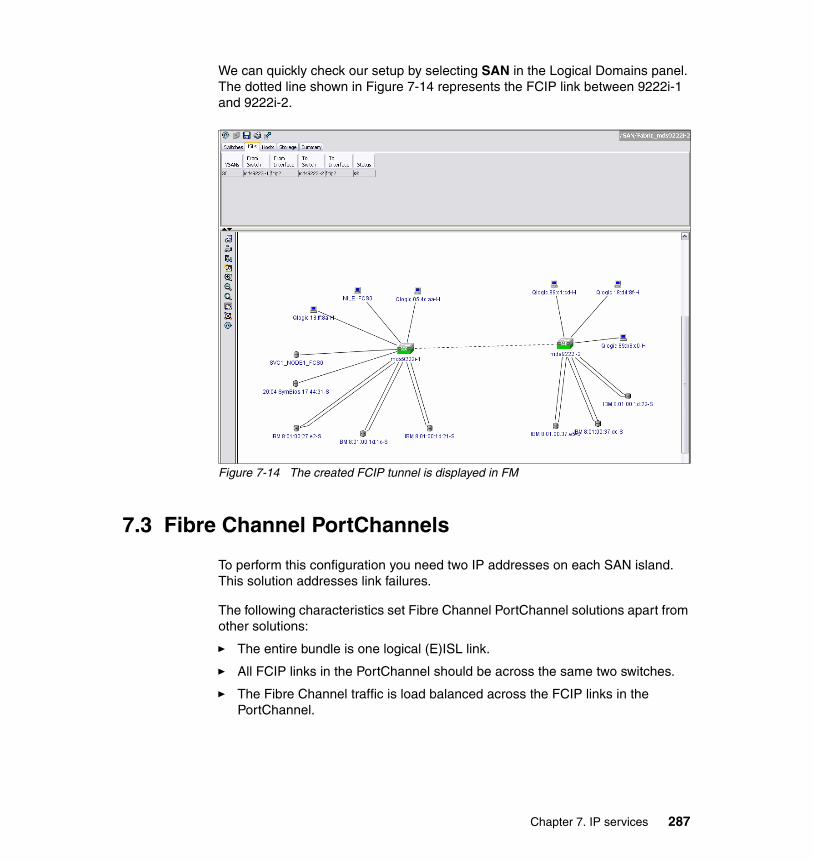
We can quickly check our setup by selecting SAN in the Logical Domains panel. The dotted line shown in Figure 7-14 represents the FCIP link between 9222i-1 and 9222i-2.
Figure 7-14 The created FCIP tunnel is displayed in FM
7.3 Fibre Channel PortChannels
To perform this configuration you need two IP addresses on each SAN island. This solution addresses link failures.
The following characteristics set Fibre Channel PortChannel solutions apart from other solutions:
� The entire bundle is one logical (E)ISL link.
� All FCIP links in the PortChannel should be across the same two switches.
� The Fibre Channel traffic is load balanced across the FCIP links in the PortChannel.
Chapter 7. IP services 287

7.4 Creating FC PortChannels
In the topics that follow we show how to create PortChannels in our environment.
7.4.1 Creating another FCIP tunnel using FM
We again select the FCIP tunnel wizard, as shown in Figure 7-7 on page 279. We have to go through the five steps required to configure a second FCIP tunnel. The first step, shown in Figure 7-15, asks for the switch pairs.
Figure 7-15 FM FCIP Wizard panel 1 of 5
288 Implementing an IBM/Cisco SAN

In the panel, shown in Figure 7-16, we configure which Gigabit Ethernet interfaces will make up the link. Highlight the correct interface from each switch and click Next. In this example, we connect interface gigE1/2 on both switches.
Figure 7-16 FM FCIP Wizard panel 2 of 4
You can set up IPsec for your link in this panel and set your Ethernet frame size.
Chapter 7. IP services 289

In Figure 7-17 we show how to create the FCIP ISL with the properties that we want. We code the IP addresses of the GigE interfaces.
Figure 7-17 FM FCIP Wizard panel 3 of 5
We use a different subnet, which is recommended but is not a requirement. Your interfaces may be across a routed network, and you have the ability on this panel to add IP routes. To do this select the Add IP Routes button and fill in the route details. Press Next and addresses from different subnets can be used, combined with static routes defined on each switch indicating the correct path.
290 Implementing an IBM/Cisco SAN

Click Next to continue. In the next panel (Figure 7-18), we configure the FCIP tunnel properties as described in more detail in Figure 7-9 on page 281.
Figure 7-18 FM FCIP Wizard panel 4 of 5
Chapter 7. IP services 291

Figure 7-19 is the final panel and we select our VSAN list and trunk mode.
Figure 7-19 FM FCIP Wizard panel 5 of 5
We select the default VSAN for this interface and configure the trunking behavior for trunk and click Finish.
292 Implementing an IBM/Cisco SAN

In Figure 7-20, we can see the two individual FCIP links in the FM map. Notice that the FCIP links show up as dotted lines to distinguish them from FC ISLs.
Figure 7-20 FM map display of FCIP interfaces
Chapter 7. IP services 293

7.4.2 Creating a PortChannel on FCIP tunnels using FMNow we show how to create a PortChannel on the FCIP tunnel using the GUI.
1. We start the PortChannel wizard, as shown in Figure 7-21.
Figure 7-21 Starting the Port Channel wizard
Note: The maximum number of Fibre Channel ports that can be put into a Fibre Channel PortChannel is 16.
294 Implementing an IBM/Cisco SAN

2. In the first panel of the wizard (Figure 7-22) we identify the switch pair that will be linked by the PortChannel. In our case, Create New is automatically selected (because there are no existing links to edit).
Figure 7-22 FM Port Channel Wizard panel 1 of 3
Note: Allow sufficient time after creating FCIP tunnel links before creating a channel so that Fabric Manager can discover all the new links. You could press Ctlr+R on FM to manually force a rediscover of the fabric.
Chapter 7. IP services 295

3. Highlight the links that will make up the PortChannel and, if necessary, using the arrow keys, move them from the Available to the Selected column (Figure 7-23). Click Next to proceed.
Figure 7-23 FM Port Channel Wizard panel 2 of 3
Tip: Select the Dynamically form Port Channel Group from selected ISLs check box if you want to dynamically create the PortChannel and make the ISL properties identical for the admin, trunk, speed, and VSAN attributes.
296 Implementing an IBM/Cisco SAN
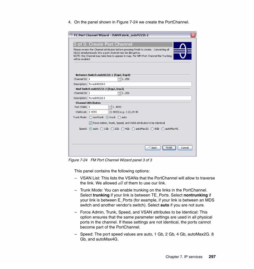
4. On the panel shown in Figure 7-24 we create the PortChannel.
Figure 7-24 FM Port Channel Wizard panel 3 of 3
This panel contains the following options:
– VSAN List: This lists the VSANs that the PortChannel will allow to traverse the link. We allowed all of them to use our link.
– Trunk Mode: You can enable trunking on the links in the PortChannel. Select trunking if your link is between TE_Ports. Select nontrunking if your link is between E_Ports (for example, if your link is between an MDS switch and another vendor's switch). Select auto if you are not sure.
– Force Admin, Trunk, Speed, and VSAN attributes to be Identical: This option ensures that the same parameter settings are used in all physical ports in the channel. If these settings are not identical, the ports cannot become part of the PortChannel.
– Speed: The port speed values are auto, 1 Gb, 2 Gb, 4 Gb, autoMax2G. 8 Gb, and autoMax4G.
Chapter 7. IP services 297

5. In the pop-up shown in Figure 7-25 we confirm that we want to create the PortChannel.
Figure 7-25 Confirm creation of the PortChannel
7.4.3 Implementing iSCSI
To demonstrate the steps involved in an iSCSI implementation we use the small test environment shown in Figure 7-26.
Figure 7-26 Test environment
Note: In our example we allowed all VSANs to traverse this PortChannel. In a production environment ensure that only the necessary VSANs are configured for its use. The reason for this is the limited bandwidth associated with the WAN connections.
Important: The FM PortChannel wizard resets FCIP tunnels involved in the process of PortChannel creation, and therefore it is disruptive for any extended zones or IVR zones making use of those FCIP tunnels. Each tunnel making part of the PortChannel will be taken down and then brought up as part of the configuration process.
298 Implementing an IBM/Cisco SAN

One IBM SAN Volume Controller cluster is connected to an MDS 9222i equipped with an integrated 18/4 MSM module. One interface of the MSM module is connected to an Ethernet switch. Our Windows XP workstation and the Windows 2003 server are connected to the same IP network.
7.4.4 Target configuration
As is true with any implementation, make sure to take the appropriate time to check all the relevant compatibility and support matrixes. For example, if you plan on having Windows 2003 iSCSI initiators and the SVC as back-end storage, check the Windows 2003 compatibility matrix where you should find supported network cards (NIC), service packs, and additional recommendations. Cross-reference this information with what you find from the storage matrix compatibility:
http://www.microsoft.com/windowsserver2003/technologies/storage/iscsi/default.mspx
The IBM storage and SVC interoperability sites are a useful references for ensuring that you have a supported matrix:
http://www-03.ibm.com/systems/support/storage/config/ssic/displayesssearchwithoutjs.wss?start_over=yes
http://www-03.ibm.com/systems/storage/software/virtualization/svc/interop.html
Also check the Cisco Interoperability site for compatibility:
http://www.cisco.com/en/US/docs/storage/san_switches/mds9000/interoperability/matrix/Matrix.pdf
LicencesDepending on which module is installed, we need to activate this on a module-by-module basis:
� SAN extension over IP package for IPS-8 modules (SAN_EXTN_OVER_IP)
� SAN extension over IP package for IPS-4 modules (SAN_EXTN_OVER_IP_IPS4)
� SAN extension over IP package for MPS-14/2 modules (SAN_EXTN_OVER_IP_IPS2)
Note: The Cisco MDS management interface, mgt0, must be in an IP network address range that is different from the GigabitEthernet port.
Chapter 7. IP services 299
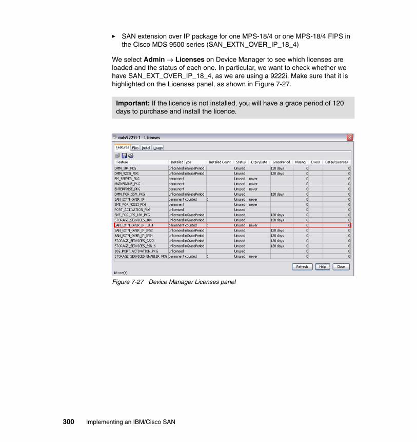
� SAN extension over IP package for one MPS-18/4 or one MPS-18/4 FIPS in the Cisco MDS 9500 series (SAN_EXTN_OVER_IP_18_4)
We select Admin → Licenses on Device Manager to see which licenses are loaded and the status of each one. In particular, we want to check whether we have SAN_EXT_OVER_IP_18_4, as we are using a 9222i. Make sure that it is highlighted on the Licenses panel, as shown in Figure 7-27.
Figure 7-27 Device Manager Licenses panel
Important: If the licence is not installed, you will have a grace period of 120 days to purchase and install the licence.
300 Implementing an IBM/Cisco SAN

Enabling iSCSIWe select Admin → Feature Control on Device Manager, as shown in Figure 7-28.
Figure 7-28 Device Manager Admin drop-down menu
We go to the iSCSI feature and click Enable in the drop-down menu, as shown in Figure 7-29. Then we click Apply at the lower end of the Feature Control panel.
Figure 7-29 Device Manager Feature Control
iSCSI feature is now enabled for the 9222i-1 switch.
Chapter 7. IP services 301

7.4.5 Enabling iSCSI on the module
We now need to enable iSCSI on the module that we will use for our configuration. In our case we use module 1. We use the command-line interface to perform this function.
First we check to see whether iSCSI is already enabled by displaying the iSCSI port that we are going to use. In Example 7-8 we use iSCSI interface iSCSI 1/4. We can see that this interface does not exist. If the port does exist then iSCSI is already enabled on this module.
Example 7-8 Show iSCSI interface
mds9222i-1# show interface iscsi 1/4 ^Invalid range at '^' marker.
If it is not already enabled, we need to enable our module for iSCSI and then perform the same command as before to make sure that it is ready (Example 7-9).
Example 7-9 Enable iSCSI on module 1
mds9222i-1# configure terminalmds9222i-1(config)# iscsi enable module 1mds9222i-1(config)# show interface iscsi 1/4iscsi1/4 is down (Administratively down) Hardware is GigabitEthernet Port WWN is 20:13:00:0d:ec:82:3d:00 Admin port mode is ISCSI snmp link state traps are enabled Port vsan is 1 iSCSI initiator is identified by name Number of iSCSI session: 0 (discovery session: 0) Number of TCP connection: 0 Configured TCP parameters Local Port is 3260 PMTU discover is enabled, reset timeout is 3600 sec Keepalive-timeout is 60 sec Minimum-retransmit-time is 300 ms Max-retransmissions 4 Sack is enabled QOS code point is 0 Maximum allowed bandwidth is 1000000 kbps Minimum available bandwidth is 70000 kbps Configured round trip time is 1000 usec
302 Implementing an IBM/Cisco SAN

Send buffer size is 4096 KB Congestion window monitoring is enabled, burst size is 50 KB
We can now continue with our configuration using Device Manager.
7.4.6 Configuring GigabitEthernet for iSCSI
We use interface gigE 1/4 for our configuration:
1. Open Device Manager and right-click the port, then select Configure in the drop-down menu, as shown in Figure 7-30.
Figure 7-30 Device Manager Interface drop-down menu
Chapter 7. IP services 303

2. Select Edit IP Address, as shown in Figure 7-31.
Figure 7-31 Device Manager Interface panel
3. Select Create, as shown in Figure 7-32.
Figure 7-32 Device Manager IP Address panel
4. Enter the IP address in the fields provided (Figure 7-33). The format is IP Address/Netmask.
Figure 7-33 Device Manager Create IP Address panel
304 Implementing an IBM/Cisco SAN

5. Select the Close button to return to the IP Address page, confirm that the correct IP address is set, and select the Close button (Figure 7-34).
Figure 7-34 IP address set
6. Select the check box Admin up and apply our changes (Figure 7-35).
Figure 7-35 Device Manager Interface panel
It is a good idea to check whether the interface has come up. If you want to be sure that it is working, you can ping the server where you installed the initiator, as shown in Example 7-10.
Example 7-10 ping to our iSCSI initiator
mds9222i-1# ping 10.43.86.10PING 10.43.86.10 (10.43.86.10) 56(84) bytes of data.64 bytes from 10.43.86.10: icmp_seq=2 ttl=128 time=0.397 ms64 bytes from 10.43.86.10: icmp_seq=3 ttl=128 time=0.386 ms64 bytes from 10.43.86.10: icmp_seq=4 ttl=128 time=0.410 ms
Chapter 7. IP services 305

64 bytes from 10.43.86.10: icmp_seq=5 ttl=128 time=0.410 ms
--- 10.43.86.10 ping statistics ---5 packets transmitted, 4 received, 20% packet loss, time 4010msrtt min/avg/max/mdev = 0.386/0.400/0.410/0.026 ms
7. Select the iSCSI tab. On this tab we select the Admin up check box, VSAN 200, passThrough, and ipaddress options, as shown in Figure 7-36.
Figure 7-36 Device Manager Interface panel
8. The Device Manager panel (Figure 7-37) shows that interface 4 in the MSM module is up (shows as green) and that iSCSI is enabled in this interface (small mark inside the interface).
Figure 7-37 Device Manager Interface gigE2/2
306 Implementing an IBM/Cisco SAN

At this point, iSCSI is enabled and we have a gateway working. Next we must create an initiator and targets and zone them.
7.4.7 Creating initiators
With Device Manager started:
1. Select IP → iSCSI to get the panel shown in Figure 7-38. Click Create.
Figure 7-38 Device Manager iSCSI panel
Our Windows 2003 server used for this example, Senegal, has 10.43.86.10 configured as its interface that is connected to the storage LAN network. VSAN200 is the VSAN where we have our SVC ports.
Chapter 7. IP services 307

2. Select the following check boxes:
– Persistent and System Assigned for the node WWN mapping
– Persistent and System Assigned for the port WWN mapping (as shown in Figure 7-39)
Figure 7-39 Device Manager Create iSCSI initiator panel
3. After we select Create, we have the IP address of Senegal registered as an iSCSI initiator, and we have dynamically generated a WWN for it, as shown in Figure 7-40.
Also, pWWN and nWWN were dynamically generated, and they are persistent because we checked the Persistent check box.
Figure 7-40 Device Manager iSCSI Initiators panel
308 Implementing an IBM/Cisco SAN

7.4.8 Creating targets
We use an IBM SAN Volume Controller for our example.
To create iSCSI targets using Device Manager:
1. Select IP → SCSI → Targets → Create, as shown in Figure 7-41.
Figure 7-41 Device Manager iSCSI Targets panel
2. We create the name iqn.com.cisco.itsocl1.n1p4 and pick node1 port 4 WWN from the Port WWN drop-down menu. We set Initiator Access to ALL because we have zoning and LUN masking to control the access.
There are multiple options for access control. One is access by IP address or iqn.xxx name. This can be done at the LUN level as well. The other method is by utilizing Fibre Channel zoning. Since each iSCSI initiator gets its own pWWN per IP address, zoning by pWWN is feasible and preferred. Cisco’s MDS does allow for zoning by IP address or iqn.xxx name as well.
Chapter 7. IP services 309

3. We choose gigE 1/4 as the only interface where that target will be mapped (Figure 7-42).
Figure 7-42 Device Manager Create iSCSi Targets panel
After we select Create, we have itsosvccl1 node 1 port 4 registered as an iSCSI target (Figure 7-43).
Figure 7-43 Device Manager iSCSI Targets panel
At this point our initiators and targets are created. We are ready to zone targets and initiators as we do for FC. After zoning, we must load the client portion of the code into the server and configure it before we are able to map disks from the SVC to the server.
310 Implementing an IBM/Cisco SAN

7.4.9 Zoning iSCSI initiators
As stated previously, there are multiple options for access control. One is access by IP address or iqn.xxx name. This can be done at the LUN level as well. The other method is by utilizing Fibre Channel zoning. Since each iSCSI initiator gets its own pWWN per IP address, zoning by pWWN is feasible and preferred. Cisco’s MDS allows for zoning by IP address or iqn.xxx name.
Guidelines for zoning iSCSI hosts and the SVCIn a conventional Fibre Channel SAN, there will normally be a number of SAN paths between a particular SVC I/O group and the server HBA ports that use the VDisks supplied by that I/O group. A multipathing device driver is run on the server to resolve these multiple paths into a single logical device to which the server can perform I/O.
The multipathing device driver also provides failover and path recovery functions that deal with scenarios where the SAN fabric paths change or fail. The present iSCSI solution only supports a single path between the iSCSI host NIC and the SVC VDisk, and there is no multipathing driver in the iSCSI host. This means that there is no recovery from errors and it is not possible to concurrently upgrade the SVC firmware while maintaining connectivity from an iSCSI host system.
As such, it is inappropriate for the SVC to present the VDisk at multiple ports in the Fibre Channel SAN, and to prevent this the user must select a single SVC port in each SVC I/O group that is to be associated with each iSCSI host. Zoning is then applied in the MDS switch so that each iSCSI host can see only one SVC port in each SVC I/O group. If multiple iSCSI hosts are in use, the hosts should be evenly spread across the ports in each SVC I/O group. The SVC svctask mkvdiskhostmap command should then be used to ensure that each SVC VDisk is mapped to a single NIC in the server.
In our example we configured the SVC and the DS4500 into a zone called SVC_BACKEND. We now configure the host to SVC using the wizard.
Creating zones using the Fabric Manager iSCSi Setup WizardSince the iSCSI initiator has not logged into the switch at this point, manually adding the pWWN (iSCSI initiator was created previously) into a zone is required. Then we also need to add the pWWN of the storage.
Chapter 7. IP services 311

The easiest way to accomplish this task is to use the Fabric Manager iSCSI Setup Wizard (Figure 7-44).
Figure 7-44 Fabric Manager iSCSI Setup Wizard
312 Implementing an IBM/Cisco SAN

To do this:
1. A portion of our work was done when we created the initiator. A list of known initiators is displayed in the first panel of the Fabric Manager iSCSI Setup Wizard, as shown in Figure 7-45. In our example, there is just one initiator, Senegal, with IP address 10.43.86.10. We highlight it and click Next.
Figure 7-45 Fabric Manager iSCSI Wizard panel 1 of 3
Chapter 7. IP services 313

2. In the next step, all known targets are displayed (Figure 7-46). We select both and click Add, located in the middle of the upper and lower panels. We click Next.
Figure 7-46 Fabric Manager iSCSI Wizard panel 2 of 3
314 Implementing an IBM/Cisco SAN

3. Once the targets are selected, we are able to name our zone. Cisco’s MDS prompts us to name it starting with the prefix iSCSI (Figure 7-47). We click Finish → Commit to activate our changes.
Figure 7-47 Fabric Manager iSCSI Wizard panel 3 of 3
4. Click Continue Activation to continue and save the configuration, as shown in Figure 7-48.
Figure 7-48 Activation of new zoneset
Note: For easier management we recommend prefixing the zone names so that they start with ISCSI (for example, ISCSI_senegal_itsocl1).
Chapter 7. IP services 315

5. Wait for the zone addition and activation to complete then select the Close buttons, as shown in Figure 7-49.
Figure 7-49 Successful completion of iSCSI zone
316 Implementing an IBM/Cisco SAN

In Figure 7-50 in the upper right panel, last column, we can see the status of our initiators and targets. In our case, the initiator is Not in Fabric. This is to be expected since we have not configured the client at this stage.
Figure 7-50 Fabric Manager zone sets and zone display
At this point we are ready to load the client code and initiator into the server. Once we have the code loaded and we have the initiator driver configured, we can assign volumes from the SVC to the server.
7.4.10 Client configuration
Before implementing iSCSI check the compatibility matrix for the different components that comprise your solution.
The Microsoft iSCSI Software Initiator supported hardware list is found at:
http://www.microsoft.com/windowsserver2003/technologies/storage/iscsi/default.mspx
Note: At the time of this writing, Microsoft iSCSI Software Initiator Version 2.07 was released, but we used Microsoft iSCSI Software Initiator Version 1.06 for our implementation due to its compatibility with IBM SVC 4.3.0.
Chapter 7. IP services 317

Use the link below to access the Cisco interoperability site and determine the correct iSCSI software required:
http://www.cisco.com/en/US/docs/storage/san_switches/mds9000/interoperability/matrix/Matrix5.html#wp266259
In our case this was 1.06, as shown in Figure 7-51.
Figure 7-51 SVC software interoperability
Downloading the Microsoft iSCSI Software InitiatorThe Microsoft iSCSI Software Initiator is obtained from the following link:
http://www.microsoft.com/downloads/details.aspx?FamilyID=a6515fb0-2b6f-4a1f-a10b-0b8fe88d256d&DisplayLang=en
318 Implementing an IBM/Cisco SAN

We click the Download files below link, as shown in Figure 7-52.
Figure 7-52 Microsoft iSCSI Software Initiator Version 1.06 Web page
Notice: Microsoft product images are reprinted with permission from Microsoft Corporation.
Chapter 7. IP services 319

We pick the 32-bit version, as shown in Figure 7-53, because we are running our test in a 32-bit Windows 2003 server.
Figure 7-53 Microsoft iSCSI Software Initiator Version 1.06 download Web page
Installing Microsoft iSCSI Software InitiatorIn this section we install the Microsoft iSCSI Software Initiator in a server equipped with two Ethernet cards. One of these is dedicated to the storage LAN network. If you are going to implement iSCSI with high availability in mind, the installation process is the same.
To install the iSCSI Initiator package, we run the appropriate MSI installer package by double-clicking the file icon (Figure 7-54) from an Explorer window. You must be logged in as an administrator to install the Microsoft iSCSI Software Initiator package.
Figure 7-54 iSCSI initiator installation package icon
320 Implementing an IBM/Cisco SAN

The first panel we see is the Wizard welcome panel, as shown in Figure 7-55.
Figure 7-55 Microsoft iSCSI Initiator Setup Wizard welcome panel
From there:
1. Choose the install location. We use the default value, as shown in Figure 7-56. This operation is conducted by the superuser (in this case, administrator). We do not want anyone else to have access to this software, so we leave Just me checked and select Next.
Figure 7-56 Microsoft iSCSI Initiator Select Installation Folder panel
Chapter 7. IP services 321

Before any further action takes place, the Microsoft iSCSI Initiator Wizard says that is ready to start the installation process (Figure 7-57).
Figure 7-57 Microsoft iSCSI Initiator Confirm Installation panel
2. After reading the software license agreement, check the I agree box and then click Next, as shown in Figure 7-58.
Figure 7-58 Microsoft iSCSI Initiator License Agreement panel
322 Implementing an IBM/Cisco SAN

3. Select Install Complete iSCSi Initiator (Figure 7-59).
Figure 7-59 Microsoft iSCSI Initiator iSCSI installation options
4. The End User License Agreement (EULA) appears. After reading it, click Agree (Figure 7-60).
Figure 7-60 Microsoft iSCSI Initiator End User License Agreement
Chapter 7. IP services 323

The software is installed and if everything has been successful you will see a pop-up similar to that shown in Figure 7-61.
Figure 7-61 Microsoft iSCSI Initiator Installation Program
Figure 7-62 shows a panel that contains information about how to solve a possible installation problem.
Figure 7-62 Microsoft iSCSI Initiator Installation Information
324 Implementing an IBM/Cisco SAN

5. Our installation was successful, so we select Next. The following panel, shown in Figure 7-63, states that our installation was successful.
Figure 7-63 Microsoft iSCSI Initiator Installation complete
Configuring Microsoft iSCSI Software InitiatorA Microsoft iSCSI Initiator icon is placed on our server desktop after the successful installation, as shown in Figure 7-64
Figure 7-64 iSCSI icon
Chapter 7. IP services 325

To configure Microsoft iSCSI Software Initiator:
1. Double-click the icon to get started and click Add on the Target Portal tab, as shown in Figure 7-65.
Figure 7-65 Microsoft iSCSI Initiator Properties panel
Note: Before proceeding, make sure that you have the iSCSI target gateway IP address and your host zoned to the targets.
326 Implementing an IBM/Cisco SAN

2. Fill in the fields by entering the IP address of the gateway (Figure 7-66). The IP address 10.43.86.1 was previously configured in the MDS to act as an iSCSI target gateway.
Figure 7-66 Microsoft iSCSI Initiator Add Target Portal form
3. Once the Target Portal is established under the Available Targets tab, click Refresh, After a short period of time, all the available iSCSI targets are listed. Highlight the target and click Log on, as shown in Figure 7-67.
Figure 7-67 Microsoft iSCSI Initiator Available Targets panel
Chapter 7. IP services 327

4. After clicking Log on we are prompted for additional options (Figure 7-68). Select the check box Automatically restore this connection when the system boots.
Figure 7-68 Microsoft iSCSI Initiator Log On to Target panel
5. Repeat the same process for each target. The final result is shown in Figure 7-69.
Figure 7-69 Microsoft iSCSI Initiator Available Targets panel
328 Implementing an IBM/Cisco SAN

At this point, we are now able to assign volumes from the SVC.
7.4.11 Additional information
An in-depth discussion and implementation of iSCSI with high-availability and security considerations is available in IBM/Cisco Multiprotocol Routing: An Introduction and Implementation, SG24-7543.
Chapter 7. IP services 329

330 Implementing an IBM/Cisco SAN

Chapter 8. Analysis tools
8
© Copyright IBM Corp. 2009. All rights reserved. 331

8.1 Fabric Manager analysis tools
Fabric Manager has several tools that can be useful in monitoring the health of the fabric, the status of individual switches, test end-to-end connectivity of devices, and monitor ISL performance. The following tools will be discussed in the topics that follow:
� Switch Health� Zone Merge Analysis� Fabric Configuration Analysis� End to End Connectivity Analysis� FC Ping� FC Traceroute� Show Tech Support
8.1.1 Switch HealthThe Switch Health tool performs a check on the status of the components on each switch in the fabric. Start this tool by selecting Tools → Switch Health from the Fabric Manager menu bar, as shown in Figure 8-1.
Figure 8-1 Start Switch Health Analysis from the Fabric Manager Tools menu
332 Implementing an IBM/Cisco SAN

You will be given the Fabric Manager Switch Health Analysis window, shown in Figure 8-2. Select Start to begin the analysis. When it has performed its analysis, the results are shown under the Problems heading.
Figure 8-2 Start Switch Health Analysis
When performing health analysis you can change the default configuration of health analysis by selecting the following options, and as shown in Figure 8-3:
� Ignore Interface Link Failures.� Ignore vsanMatchIsolation Trunk Failures.
An in-depth switch health analysis using Fabric Manager will verify the status of all critical Cisco MDS switches, modules, ports, and Fibre Channel services. Over 40 conditions are checked. This tool provides a very fast, simple, and thorough way to assess Cisco MDS switch health.
Figure 8-3 Switch Health Analysis output
Chapter 8. Analysis tools 333

We can highlight specific problems and select the Details button to get further details.
8.1.2 Zone Merge AnalysisThe Zone Merge Analysis tool (available from the Zone menu) enables you to determine whether zones will merge successfully when two Cisco MDS switches are interconnected. If the interconnected switch ports allow VSANs with identical names or contain zones with identical names, then Fabric Manager verifies that the zones contain identical members. The merge analysis tool can be run before attempting a merge, or after fabrics are interconnected to determine zone merge failure causes. Figure 8-4 shows how to start the analysis.
Figure 8-4 Start Zone Merge Analysis
334 Implementing an IBM/Cisco SAN

You will be given the option to perform zone merge analysis for every VSAN in your SAN network, as shown in Figure 8-5.
Figure 8-5 Zone Merge Analysis output
8.1.3 Fabric Configuration AnalysisFabric Manager includes a Fabric Configuration Analysis tool. It compares the configurations of all Cisco MDS switches in a fabric to a reference switch or a policy file. You can define what functions to check and what type of checks to perform. The analysis can look for mismatched values and missing or extra values. If all configuration checking is performed for all functions, over 200 checks are performed for each Cisco MDS switch.
Note: We strongly recommend that you conduct zone merge analysis before merging or connecting two or more switches and initiating the zone merge process. This tool allows us to avoiding problems caused by, for example, duplicate zone names, duplicate aliases, zone membership conflicts, and so on.
Chapter 8. Analysis tools 335

To run this tool select Tools → Fabric Configuration from the Fabric Manager menu bar, as shown in Figure 8-6.
Figure 8-6 Selecting Fabric Configuration analysis
336 Implementing an IBM/Cisco SAN

Figure 8-7 shows the Fabric Configuration Analysis window. Select Compare to perform the check. In this example we have four Cisco MDS switches in our fabric:
� mds9222i-1� mds9222i-2� mds9216i-1 � mds9216i-2
We will perform analysis of all switches, and as our policy switch we choose the mds9222i-2 switch.
Figure 8-7 Comparing configuration
Before starting Fabric Configuration Analysis you can configure parameters to check during configuration analysis. You can select the Rules button, as shown in Figure 8-7, and decide what conditions will be validated during configuration analysis.
Chapter 8. Analysis tools 337

When you click the Rules button you will be presented with the conditions to define for analysis, as shown in Figure 8-8.
Figure 8-8 Select condition to validate during configuration analysis
338 Implementing an IBM/Cisco SAN

To start analysis select Compare and the configuration of the other three switches will be checked against the configuration of the mds9222i-2. As shown in Figure 8-9, inconsistencies have been found.
Figure 8-9 shows that you might be able to resolve some of the errors (indicated by the check mark). Click the Resolve Issues button to attempt to solve the selected problems.
Figure 8-9 Inconsistencies found during configuration analysis
Chapter 8. Analysis tools 339

You will be asked whether you would like to see the proposed resolutions, as shown in Figure 8-10.
Figure 8-10 Check proposed solution
340 Implementing an IBM/Cisco SAN

The proposed solution will be presented as Fabric Checker Resolution Details in a separate window, as shown in Figure 8-11.
Figure 8-11 Fabric Checker Resolution Details
Chapter 8. Analysis tools 341

When you click OK details regarding the applied solution will be presented, as shown in Figure 8-12.
Figure 8-12 Displaying the successful resolutions
8.1.4 End-to-end connectivity analysisFabric Manager’s end-to-end connectivity analysis tool uses FC Ping to verify interconnections between Cisco MDS switches and end devices (HBAs and storage devices) in a particular VSAN. In addition to basic connectivity, Fabric Manager can optionally verify the following:
� Paths that are redundant.� Zones contain at least two members.
342 Implementing an IBM/Cisco SAN

Start this tool by selecting Tools → End to End Connectivity from the Fabric Manager menu bar, as shown in Figure 8-13.
Figure 8-13 Select End-to-End Connectivity analysis from Fabric Manager menu
Chapter 8. Analysis tools 343

When you select to start end-to-end connectivity analysis you will be presented with the window shown in Figure 8-14. You can select a VSAN and the conditions to conduct the analysis.
Figure 8-14 End to End Connectivity Analysis configuration window
344 Implementing an IBM/Cisco SAN

In Figure 8-15 we have selected VSAN0020 to conduct analysis. Additionally, we decided to choose All zone options to ensure that all members within a particular zone can communicate. The Issues are shown at the bottom of the window. It states that all 132 requests have been completed successfully.
Figure 8-15 End to End Connectivity Analysis
8.1.5 FC PingFabric Manager also provides an FC Ping tool that allows you to check connectivity to end devices. the ping consists of a Port Login (PLOGI), followed by an ECHO extended link service command sourced with the switch FCID FF.FC.XX, where XX is the domain ID of the switch for that VSAN.
Chapter 8. Analysis tools 345

To use the tool, select Tools → Ping from the Fabric Manager menu, as shown in Figure 8-16.
Figure 8-16 Select FC Ping tool for connectivity analysis
As shown in Figure 8-17, you are prompted to select a source mds switch, a VSAN to use, and a target device to ping it.
Figure 8-17 FC ping selection window
346 Implementing an IBM/Cisco SAN

You do not need to remember or copy the end devices’ WWN addresses or FCIDs. You can select an end device from the list, as shown in Figure 8-18.
Figure 8-18 Select the end device to ping
When all the required information is provided you can start FC ping, as shown in Figure 8-19. In this case the FC ping was successful.
Figure 8-19 FC ing output
Chapter 8. Analysis tools 347

You can conduct an FC ping test from the CLI, as shown in Example 8-1.
Example 8-1 FC Ping tests from the CLI
mds9222i-1# show flogi database--------------------------------------------------------------------------------INTERFACE VSAN FCID PORT NAME NODE NAME--------------------------------------------------------------------------------fc1/1 20 0x14000a 50:05:07:68:01:10:37:e5 50:05:07:68:01:00:37:e5fc1/2 20 0x14000b 50:05:07:68:01:30:37:e5 50:05:07:68:01:00:37:e5fc1/3 20 0x140008 50:05:07:68:01:10:37:dc 50:05:07:68:01:00:37:dcfc1/4 20 0x140009 50:05:07:68:01:30:37:dc 50:05:07:68:01:00:37:dcfc1/14 30 0x1e0100 21:00:00:e0:8b:89:2b:cd 20:00:00:e0:8b:89:2b:cd [Nile_1]fc1/15 20 0x140400 21:00:00:e0:8b:05:48:bc 20:00:00:e0:8b:05:48:bcfc1/16 20 0x140200 21:00:00:e0:8b:05:4c:aa 20:00:00:e0:8b:05:4c:aa [Palau_1]fc1/17 50 0x7e0000 21:00:00:e0:8b:18:ff:8a 20:00:00:e0:8b:18:ff:8afc2/2 20 0x140300 20:04:00:a0:b8:17:44:32 20:04:00:a0:b8:17:44:31fc2/17 20 0x140000 50:03:08:c1:40:46:70:06 50:03:08:c1:40:06:70:06
Total number of flogi = 10.
mds9222i-1# fcping device-alias Nile_1 vsan 20No switch with the given wwn is present in the vsanmds9222i-1# fcpingdevice-alias fcid pwwnmds9222i-1# fcping fcid 0x1e0100 vsan 3028 bytes from 0x1e0100 time = 1266 usec28 bytes from 0x1e0100 time = 1222 usec28 bytes from 0x1e0100 time = 1203 usec28 bytes from 0x1e0100 time = 1243 usec28 bytes from 0x1e0100 time = 1210 usec
5 frames sent, 5 frames received, 0 timeoutsRound-trip min/avg/max = 1203/1228/1266 usecmds9222i-1# fcping pwwn 21:00:00:e0:8b:18:ff:8a vsan 5028 bytes from 21:00:00:e0:8b:18:ff:8a time = 1260 usec28 bytes from 21:00:00:e0:8b:18:ff:8a time = 1243 usec28 bytes from 21:00:00:e0:8b:18:ff:8a time = 1210 usec28 bytes from 21:00:00:e0:8b:18:ff:8a time = 1241 usec28 bytes from 21:00:00:e0:8b:18:ff:8a time = 1237 usec
5 frames sent, 5 frames received, 0 timeoutsRound-trip min/avg/max = 1210/1238/1260 usec
348 Implementing an IBM/Cisco SAN

8.1.6 FC TracerouteThe MDS NX-OS also provides a modified FC Traceroute tool as an aid in determining end-to-end connectivity. To access this tool from FM select Tools → Trace Route from the FM menu bar, as shown in Figure 8-20.
Figure 8-20 Selecting trace route
You should follow this procedure:
1. Select the source switch from the Source Switch drop-down list.
2. Select the VSAN for which to verify connectivity from the VSAN drop-down list.
3. Select the target end port for which to verify connectivity from the Target Endport drop-down list.
Chapter 8. Analysis tools 349

4. Click Start to perform the traceroute between your switch and the selected port, as shown in Figure 8-21.
Figure 8-21 Trace Route configuration window
As you see in Figure 8-22, our traceroute test has completed successfully and we have obtained the possible routes to the specified target.
Figure 8-22 Trace route possible routes
350 Implementing an IBM/Cisco SAN

Trace route analysis can be conducted from the CLI, as shown in Example 8-2.
Example 8-2 Trace route analysis from the CLI
mds9222i-1# fctrace pwwn 21:00:00:e0:8b:18:ff:8a vsan 50Route present for : 21:00:00:e0:8b:18:ff:8a20:00:00:0d:ec:2d:ca:40(0xfffcb7)20:00:00:0d:ec:82:3d:00(0xfffc7e)20:00:00:0d:ec:82:3d:00(0xfffc7e)mds9222i-1#
8.1.7 Show tech supportThe show tech support command is useful when collecting a large amount of information about your switch for troubleshooting purposes. The output can be provided to technical support representatives when reporting a problem.
You can issue a show tech support command from Fabric Manager for one or more switches in a fabric. The results of each command are written to a text file, one file per switch, in a directory that you specify. You can then view these files using Fabric Manager.
You can also save the Fabric Manager map as a JPG file. The file is saved with the name of the seed switch or fabric.
You can zip up all the files (the show tech support output and the map file image) and send the resulting zipped file to technical support.
show tech support displays the output of several show commands at once. The output varies depending on the configuration that you have.
The output is equivalent to the output of the following commands:
� show version (Example 8-3)
Example 8-3 Show version output from the CLI
mds9222i-1# show versionCisco Nexus Operating System (NX-OS) SoftwareTAC support: http://www.cisco.com/tacCopyright (c) 2002-2008, Cisco Systems, Inc. All rights reserved.The copyrights to certain works contained herein are owned byother third parties and are used and distributed under license.Some parts of this software are covered under the GNU Public
Note: Use the show tech-support command in EXEC mode to display general information about the switch when reporting a problem.
Chapter 8. Analysis tools 351

License. A copy of the license is available athttp://www.gnu.org/licenses/gpl.html.
Software BIOS: version 1.0.15 loader: version N/A kickstart: version 4.1(1) system: version 4.1(1) BIOS compile time: 07/16/08 kickstart image file is: bootflash:///m9200-s2ek9-kickstart-mz.4.1.1.bin kickstart compile time: 10/12/2020 25:00:00 [09/09/2008 06:55:47] system image file is: bootflash:/m9200-s2ek9-mz.4.1.1.bin system compile time: 8/22/2008 0:00:00 [09/09/2008 08:15:09]
Hardware cisco MDS 9222i ("4x1GE IPS, 18x1/2/4Gbps FC/Sup2") Motorola, e500v2 with 1036316 kB of memory. Processor Board ID JAE12088ZMT
Device name: mds9222i-1 bootflash: 1000440 kBKernel uptime is 1 day(s), 0 hour(s), 23 minute(s), 8 second(s)
Last reset at 299946 usecs after Mon Sep 29 19:53:17 2008
Reason: Reset Requested by CLI command reload System version: 4.1(1) Service:
� show environment (Example 8-4)
Example 8-4 Show environment output from the CLI
mds9222i-1# show environmentClock:----------------------------------------------------------Clock Model Hw Status----------------------------------------------------------A 0.0 Ok/Active
Fan:------------------------------------------------------Fan Model Hw Status------------------------------------------------------ChassisFan1 DS-2SLOT-FAN 4.0 OkFan_in_PS1 -- -- AbsentFan_in_PS2 -- -- OkFan Air Filter : NotSupported
Temperature:--------------------------------------------------------------------Module Sensor MajorThresh MinorThres CurTemp Status (Celsius) (Celsius) (Celsius)
352 Implementing an IBM/Cisco SAN

--------------------------------------------------------------------1 Outlet1 75 60 44 Ok1 Outlet2 75 65 51 Ok1 Intake1 65 50 34 Ok2 Outlet1 75 60 45 Ok2 Outlet2 75 65 53 Ok2 Intake1 65 50 40 Ok
Power Supply:Voltage: 42 Volts-----------------------------------------------------PS Model Power Power Status (Watts) (Amp)-----------------------------------------------------1 ------------ 0.00 0.00 Absent2 DS-CAC-845W 800.10 19.05 Ok
Mod Model Power Power Power Power Status Requested Requested Allocated Allocated (Watts) (Amp) (Watts) (Amp)--- ------------------- ------- ---------- --------- ---------- ----------1 DS-X9222I-K9 209.16 4.98 209.16 4.98 Powered-Up2 DS-X9248-48K9 214.20 5.10 214.20 5.10 Powered-Upfan1 DS-2SLOT-FAN 47.88 1.14 47.88 1.14 Powered-Up
Power Usage Summary:--------------------Power Supply redundancy mode: RedundantPower Supply redundancy operational mode: Redundant
Total Power Capacity 800.10 W
Power reserved for Supervisor(s) 418.32 WPower reserved for Fan Module(s) 47.88 WPower currently used by Modules 214.20 W
-------------Total Power Available 119.70 W -------------
� show module (Example 8-5)
Example 8-5 Show module output from the CLI
mds9222i-1# show moduleMod Ports Module-Type Model Status--- ----- -------------------------------- ------------------ ------------1 22 4x1GE IPS, 18x1/2/4Gbps FC/Sup2 DS-X9222I-K9 active *2 48 1/2/4/8 Gbps 4/44-Port FC Module DS-X9248-48K9 ok
Mod Sw Hw World-Wide-Name(s) (WWN)--- -------------- ------ --------------------------------------------------1 4.1(1) 1.1 20:01:00:0d:ec:82:3d:00 to 20:12:00:0d:ec:82:3d:002 4.1(1) 0.35 20:41:00:0d:ec:82:3d:00 to 20:70:00:0d:ec:82:3d:00
Chapter 8. Analysis tools 353

Mod MAC-Address(es) Serial-Num--- -------------------------------------- ----------1 00-17-94-ee-58-74 to 00-17-94-ee-58-7c JAE12088ZMT2 00-0d-ec-75-24-68 to 00-0d-ec-75-24-6c JAE1216EXLB
* this terminal session
� show hardware (Example 8-6)
Example 8-6 Show module output from the CLI
mds9222i-1# show hardwareCisco Nexus Operating System (NX-OS) SoftwareTAC support: http://www.cisco.com/tacCopyright (c) 2002-2008, Cisco Systems, Inc. All rights reserved.The copyrights to certain works contained herein are owned byother third parties and are used and distributed under license.Some parts of this software are covered under the GNU PublicLicense. A copy of the license is available athttp://www.gnu.org/licenses/gpl.html.
Software BIOS: version 1.0.15 loader: version N/A kickstart: version 4.1(1) system: version 4.1(1) BIOS compile time: 07/16/08 kickstart image file is: bootflash:///m9200-s2ek9-kickstart-mz.4.1.1.bin kickstart compile time: 10/12/2020 25:00:00 [09/09/2008 06:55:47] system image file is: bootflash:/m9200-s2ek9-mz.4.1.1.bin system compile time: 8/22/2008 0:00:00 [09/09/2008 08:15:09]
Hardware cisco MDS 9222i ("4x1GE IPS, 18x1/2/4Gbps FC/Sup2") Motorola, e500v2 with 1036316 kB of memory. Processor Board ID JAE12088ZMT
Device name: mds9222i-1 bootflash: 1000440 kBKernel uptime is 1 day(s), 0 hour(s), 26 minute(s), 12 second(s)
Last reset at 299946 usecs after Mon Sep 29 19:53:17 2008
Reason: Reset Requested by CLI command reload System version: 4.1(1) Service:--------------------------------Switch hardware ID information--------------------------------
Switch is booted up
354 Implementing an IBM/Cisco SAN

Switch type is : MDS 9222i Model number is DS-C9222I-K9 H/W version is 1.0 Part Number is 73-11019-01 Part Revision is A1 Manufacture Date is Year 12 Week 16 Serial number is FOX1216GP0C CLEI code is COM9310ARA
--------------------------------Chassis has 2 Module slots--------------------------------
Module1 ok Module type is : 4x1GE IPS, 18x1/2/4Gbps FC/Sup2 0 submodules are present Model number is DS-X9222I-K9 H/W version is 1.1 Part Number is 73-11018-06 Part Revision is B0 Manufacture Date is Year 12 Week 8 Serial number is JAE12088ZMT CLEI code is COUIAMCCAA
Module2 ok Module type is : 1/2/4/8 Gbps 4/44-Port FC Module 0 submodules are present Model number is DS-X9248-48K9 H/W version is 0.35 Part Number is 73-11289-03 Part Revision is 03 Manufacture Date is Year 12 Week 16 Serial number is JAE1216EXLB CLEI code is 0000000000
---------------------------------------Chassis has 2 PowerSupply Slots---------------------------------------
PS1 absent
PS2 ok Power supply type is: 800.10W 110v AC Model number is DS-CAC-845W H/W version is 1.2 Part Number is 341-0052-03 Part Revision is B0 Manufacture Date is Year 12 Week 15 Serial number is QCS1215109K CLEI code is CNUPAA8AAA
----------------------------------Chassis has 1 Fan slots----------------------------------
Chapter 8. Analysis tools 355

Fan1 ok Model number is DS-2SLOT-FAN H/W version is 4.0 Part Number is 800-24478-02 Part Revision is B0 Manufacture Date is Year 12 Week 13 Serial number is DCH12131591 CLEI code is CNUQABBAAC
-----------------------------------------Chassis has 1 Interface slot-----------------------------------------
Interface module ok Model number is DS-X9222-MGT H/W version is 1.0 Part Number is 73-11488-02 Part Revision is A0 Manufacture Date is Year 12 Week 6 Serial number is JAE12067IIM CLEI code is 0
� show running-config (Example 8-7)
Example 8-7 Show running-config from the CLI
mds9222i-1# show running-configversion 4.1(1)feature fcipfeature dpvmrole name default-role description This is a system defined role and applies to all users. rule 5 permit show feature environment--- truncateed --- rule 1 permit show feature system vsan policy deny permit vsan 10-10username admin password 5 $1$w.fBQFNO$FLQdKnS2V65A39FbZjQwd1 role network-adminfeature telnetntp server 10.1.1.1ip domain-lookupip host mds9222i-1 9.43.86.147kernel core target 0.0.0.0kernel core limit 1aaa group server radius radiussnmp-server contact Jacosnmp-server user admin network-admin auth md5 0x5f504840456bd68853696954ecfa9f0b priv --- truncateed --- snmp-server host 9.43.86.81 traps version 2c public udp-port 2162callhome contract-id ABC12345--- truncateed --- fcip profile 1
356 Implementing an IBM/Cisco SAN

ip address 10.1.1.1 tcp max-bandwidth-mbps 1000 min-available-bandwidth-mbps 500 round-trip-time-us 600ip access-list Test permit ip any anyvsan database vsan 10 vsan 20fcsp enabledevice-alias database device-alias name Nile_1 pwwn 21:00:00:e0:8b:89:2b:cdvsan database vsan 200 interface iscsi1/4--- truncateed --- vsan 50 interface fc2/37islb distributeinterface iscsi1/1--- truncateed --- interface iscsi1/4 switchport initiator id ip-address mode pass-thru switchport description GB_iSCSI no shutdowninterface mgmt0 ip address 9.43.86.147 255.255.252.0--- truncateed --- fcflow stats module 2 index 24 0x150000 0x140400 0xffffff vsan 20ip default-gateway 9.43.85.1switchname mds9222i-1cli alias name gigint interface gigabitethernetfeature iscsiiscsi initiator ip-address 10.43.86.10 static nWWN 23:03:00:0d:ec:82:3d:02vsan 200boot kickstart bootflash:/m9200-s2ek9-kickstart-mz.4.1.1.binboot system bootflash:/m9200-s2ek9-mz.4.1.1.binfeature ivrivr distributeivr natdpvm database pwwn 21:00:00:e0:8b:05:4c:aa vsan 20dpvm activate forcedpvm commit--- truncateed --- interface fc2/48interface GigabitEthernet1/1 ip address 10.1.1.1 255.255.255.0 switchport mtu 2300 no shutdown--- truncateed --- interface port-channel 20 switchport mode E channel mode active switchport description To mds9222i-2 no shutdown
Chapter 8. Analysis tools 357
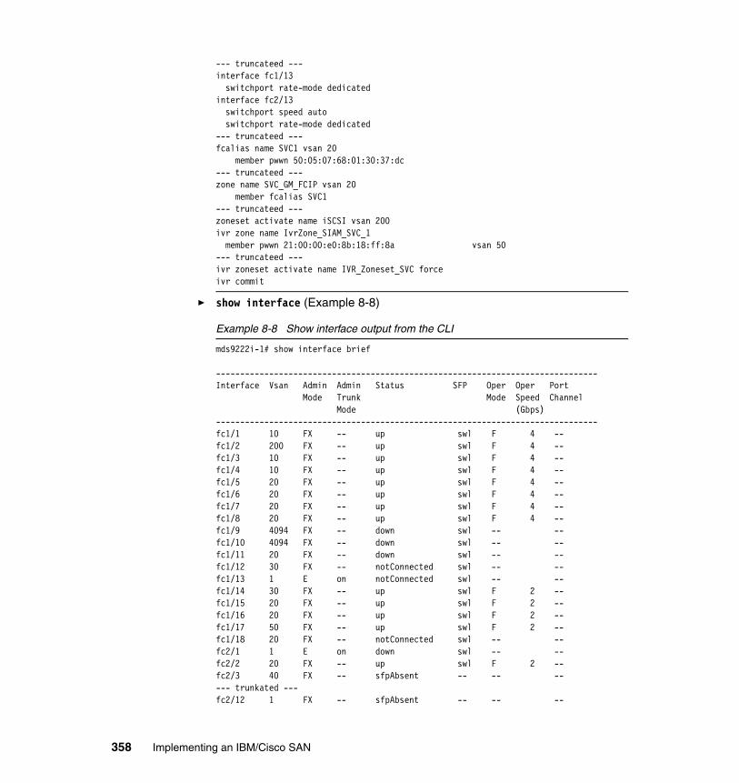
--- truncateed --- interface fc1/13 switchport rate-mode dedicatedinterface fc2/13 switchport speed auto switchport rate-mode dedicated--- truncateed --- fcalias name SVC1 vsan 20 member pwwn 50:05:07:68:01:30:37:dc--- truncateed --- zone name SVC_GM_FCIP vsan 20 member fcalias SVC1--- truncateed --- zoneset activate name iSCSI vsan 200ivr zone name IvrZone_SIAM_SVC_1 member pwwn 21:00:00:e0:8b:18:ff:8a vsan 50--- truncateed --- ivr zoneset activate name IVR_Zoneset_SVC forceivr commit
� show interface (Example 8-8)
Example 8-8 Show interface output from the CLI
mds9222i-1# show interface brief
-------------------------------------------------------------------------------Interface Vsan Admin Admin Status SFP Oper Oper Port Mode Trunk Mode Speed Channel Mode (Gbps)-------------------------------------------------------------------------------fc1/1 10 FX -- up swl F 4 --fc1/2 200 FX -- up swl F 4 --fc1/3 10 FX -- up swl F 4 --fc1/4 10 FX -- up swl F 4 --fc1/5 20 FX -- up swl F 4 --fc1/6 20 FX -- up swl F 4 --fc1/7 20 FX -- up swl F 4 --fc1/8 20 FX -- up swl F 4 --fc1/9 4094 FX -- down swl -- --fc1/10 4094 FX -- down swl -- --fc1/11 20 FX -- down swl -- --fc1/12 30 FX -- notConnected swl -- --fc1/13 1 E on notConnected swl -- --fc1/14 30 FX -- up swl F 2 --fc1/15 20 FX -- up swl F 2 --fc1/16 20 FX -- up swl F 2 --fc1/17 50 FX -- up swl F 2 --fc1/18 20 FX -- notConnected swl -- --fc2/1 1 E on down swl -- --fc2/2 20 FX -- up swl F 2 --fc2/3 40 FX -- sfpAbsent -- -- ----- trunkated ---fc2/12 1 FX -- sfpAbsent -- -- --
358 Implementing an IBM/Cisco SAN

fc2/13 40 E on up swl E 2 --fc2/14 1 FX -- sfpAbsent -- -- --fc2/15 1 FX -- sfpAbsent -- -- --fc2/16 1 FX -- sfpAbsent -- -- --fc2/17 20 FX -- up swl F 2 --fc2/18 1 FX -- sfpAbsent -- -- ----- trunkated ---fc2/24 1 FX -- sfpAbsent -- -- --fc2/25 1 E on down swl -- --fc2/26 1 FX -- sfpAbsent -- -- ----- trunkated ---fc2/36 1 FX -- sfpAbsent -- -- --fc2/37 50 E on trunking swl TE 2 --fc2/38 1 FX -- sfpAbsent -- -- ----- trunkated ---fc2/48 1 FX -- sfpAbsent -- -- --
-------------------------------------------------------------------------------Interface Status Oper Mode Oper Speed (Gbps)-------------------------------------------------------------------------------iscsi1/1 down --iscsi1/2 down --iscsi1/3 down --iscsi1/4 up ISCSI 1
-------------------------------------------------------------------------------Interface Status Speed (Gbps)-------------------------------------------------------------------------------sup-fc0 up 1--------------------------------------------------------------------------------Interface Status IP Address Speed MTU Port Channel--------------------------------------------------------------------------------GigabitEthernet1/1 up 10.1.1.1/24 1 Gbps 2300 --GigabitEthernet1/2 up 10.2.2.1/24 1 Gbps 2300 --GigabitEthernet1/3 up 10.3.3.1/24 1 Gbps 2300 --GigabitEthernet1/4 up 10.43.86.1/24 1 Gbps 1500 --
-------------------------------------------------------------------------------Interface Vsan Admin Admin Status Oper Profile Eth Int Port-channel Mode Trunk Mode Mode-------------------------------------------------------------------------------fcip1 1 auto on srcUnbound -- -- --fcip2 1 E on trunking TE 1 GigabitEthernet1/1 port-channel 20fcip3 1 E on trunking TE 2 GigabitEthernet1/2 port-channel 20
-------------------------------------------------------------------------------Interface Status IP Address Speed MTU-------------------------------------------------------------------------------mgmt0 up 9.43.86.147/22 100 Mbps 1500
Chapter 8. Analysis tools 359

-------------------------------------------------------------------------------Interface Vsan Admin Status Oper Oper IP Trunk Mode Speed Address Mode (Gbps)-------------------------------------------------------------------------------port-channel 20 1 on trunking TE 2 --
� show accounting log (Example 8-9)
Example 8-9 Show accounting log output from the CLI
mds9222i-1# show accounting log
Tue Sep 23 23:30:40 2008:update:snmp_4522_9.167.197.161:admin:Interface fc1/4 state updated to upTue Sep 23 23:36:17 2008:start:9.167.197.161@pts/2:admin:Tue Sep 23 23:36:20 2008:update:9.167.197.161@pts/2:admin:terminal length 0 (SUCCESS)Tue Sep 23 23:36:20 2008:update:9.167.197.161@pts/2:admin:terminal session-timeout 30 (SUCCESS)Wed Sep 24 17:45:34 2008:update:console0:root:enabled (null)Wed Sep 24 17:45:34 2008:update:console0:root:configure terminal ; password strength-check (SUCCESS)Wed Sep 24 17:45:35 2008:update:console0:root:updated v3 user : adminWed Sep 24 17:45:35 2008:update:console0:root:configure terminal ; username admin password ******** role network-admin (SUCCESS)Wed Sep 24 17:46:49 2008:update:console0:root:enabled (null)Wed Sep 24 17:46:49 2008:update:console0:root:configure terminal ; password strength-check (SUCCESS)Wed Sep 24 17:46:49 2008:update:console0:root:configure terminal ; interface mgmt0 (SUCCESS)
---- truncated ----
� show process (Example 8-10)
Example 8-10 Show process output from the CLI
mds9222i-1# show processes
PID State PC Start_cnt TTY Type Process----- ----- -------- ----------- ---- ---- ------------- 1 S ff67dbc 1 - O init 2 S 0 1 - O ksoftirqd/0 3 S 0 1 - O desched/0 4 S 0 1 - O events/0 5 S 0 1 - O khelper 10 S 0 1 - O kthread 29 S 0 1 - O kblockd/0 64 S 0 1 - O pdflush 65 S 0 1 - O pdflush 67 S 0 1 - O aio/0 66 S 0 1 - O kswapd0 931 S 0 1 - O kjournald 936 S 0 1 - O kjournald 1237 S 0 1 - O kjournald
360 Implementing an IBM/Cisco SAN

1244 S 0 1 - O kjournald 1251 S 0 1 - O kjournald 1533 S ff052e0 1 - O portmap--- truncated ---2308 S ff12dbc 1 - O cisco 2311 S eb91a80 1 - VL clis 2312 S fb59248 1 - VL vshd 2320 S fd9d248 1 - VU xbar_client--- truncated ---2372 S eb2c730 1 - VL cdp 2373 S ff67dbc 1 - O dhcpd 2375 S e9a5730 1 - VL radius 2376 S fef8248 1 - VL ipv6_dummy 2377 S fbace08 1 - VU fspf 2380 S fc55dbc 1 - VU device-alias 2381 S fc9ddbc 1 - VU epp 2382 S fb75dbc 1 - VU fcdomain--- truncated --- 2466 S fd95248 1 - O proc_mgr 2467 S fd85248 1 - VU fvpd 2468 S fb62dbc 1 - VU fc-tunnel 2469 S fc9ddbc 1 - VU ipacl 2472 S fb65dbc 1 - VU fc-redirect 2473 S f84cdbc 1 - VU ivr--- truncated --- 20762 S f588dbc 1 0 O vsh22208 S fcaedbc 1 - O dcos_sshd22210 S f588dbc 1 1 O vsh23884 Z 0 1 - O df23885 Z 0 1 - O df25087 S fef40ac 1 5 O more25088 S f588248 1 5 O vsh25089 R ff1e0ac 1 - O ps--- truncated --- - NR - 0 - VL scheduler - NR - 0 - VU sdv - NR - 0 - VU sfm - NR - 0 - VU sme - NR - 0 - VU vbuilder
State: R(runnable), S(sleeping), Z(defunct)
Type: U(unknown), O(non sysmgr) VL(vdc-local), VG(vdc-global), VU(vdc-unaware) NR(not running), ER(terminated etc)
Chapter 8. Analysis tools 361

� show process log (Example 8-11)
Example 8-11 Show process log output from the CLI
mds9222i-1# show processes logProcess PID Normal-exit Stack Core Log-create-time--------------- ------ ----------- ----- ----- ---------------installer 23639 N N N Wed Sep 17 00:19:24 2008
� show processes log (Example 8-12)
Example 8-12 Show process log details output from the CLI
mds9222i-1# show processes log details======================================================Service: installerDescription: Installer
Started at Wed Sep 17 00:19:22 2008 (403287 us)Stopped at Wed Sep 17 00:19:24 2008 (247072 us)Uptime: 2 seconds
Start type: SRV_OPTION_RESTART_STATELESS (23)Death reason: SYSMGR_DEATH_REASON_FAILURE_NOCALLHOME (12)Last heartbeat 0.00 secs agoRLIMIT_AS: 46777216System image name: m9200-s2ek9-mz.4.1.1.binSystem image version: 4.1(1) S16Exit code: SYSMGR_EXITCODE_FAILURE_NOCALLHOME (20)
PID: 23639SAP: 0UUID: 0
======================================================
� show tech-support (brief) (Example 8-13)
Example 8-13 Show tech-support output from the CLI (brief version)
mds9222i-1# show tech-support briefSwitch Name : mds9222i-1Switch Type :Kickstart Image : 4.1(1) bootflash:///m9200-s2ek9-kickstart-mz.4.1.1.binSystem Image : 4.1(1) bootflash:/m9200-s2ek9-mz.4.1.1.binIP Address/Mask : 9.43.86.147/22Switch WWN : 20:00:00:0d:ec:82:3d:00No of VSANs : 7Configured VSANs : 1,10,20,30,40,50,200
VSAN 1: name:VSAN0001, state:active, interop mode:default
362 Implementing an IBM/Cisco SAN

domain id:0xad(173), WWN:20:01:00:0d:ec:82:3d:01 active-zone:<NONE>, default-zone:deny
VSAN 10: name:VSAN0010, state:active, interop mode:default domain id:0x0a(10), WWN:20:0a:00:0d:ec:82:3d:01 active-zone:<NONE>, default-zone:deny
VSAN 20: name:VSAN0020, state:active, interop mode:default domain id:0x14(20), WWN:20:14:00:0d:ec:82:3d:01 active-zone:size:, default-zone:deny
VSAN 30: name:VSAN0030, state:active, interop mode:default domain id:0x1e(30), WWN:20:1e:00:0d:ec:82:3d:01 active-zone:<NONE>, default-zone:deny
VSAN 40: name:ITSO_VSAN_40, state:active, interop mode:2 domain id:0x6f(111), WWN:20:28:00:0d:ec:82:3d:01 active-zone:<NONE>, default-zone:deny
VSAN 50: name:VSAN0050, state:active, interop mode:default domain id:0x7e(126), WWN:20:32:00:0d:ec:82:3d:01 active-zone:size:, default-zone:deny
VSAN 200: name:VSAN0200, state:active, interop mode:default domain id:0x54(84), WWN:20:c8:00:0d:ec:82:3d:01 active-zone:<NONE>, default-zone:deny
-------------------------------------------------------------------------------Interface Vsan Admin Admin Status SFP Oper Oper Port Mode Trunk Mode Speed Channel Mode (Gbps)-------------------------------------------------------------------------------fc1/1 20 FX -- up swl F 4 --fc1/2 20 FX -- up swl F 4 --fc1/3 20 FX -- up swl F 4 --fc1/4 10 FX -- up swl F 4 --fc1/5 20 FX -- up swl F 4 --fc1/6 20 FX -- up swl F 4 --fc1/7 20 FX -- up swl F 4 --fc1/8 20 FX -- up swl F 4 --fc1/9 4094 FX -- down swl -- --fc1/10 4094 FX -- down swl -- --fc1/11 20 FX -- down swl -- --fc1/12 30 FX -- notConnected swl -- --fc1/13 1 E on notConnected swl -- --fc1/14 30 FX -- up swl F 2 --fc1/15 20 FX -- up swl F 2 --fc1/16 20 FX -- up swl F 2 --fc1/17 50 FX -- up swl F 2 --fc1/18 20 FX -- notConnected swl -- --fc2/1 1 E on down swl -- --fc2/2 20 FX -- up swl F 2 --fc2/3 40 FX -- sfpAbsent -- -- --
Chapter 8. Analysis tools 363

fc2/4 20 FX -- sfpAbsent -- -- --fc2/5 40 FX -- sfpAbsent -- -- --fc2/6 40 FX -- sfpAbsent -- -- --fc2/7 40 FX -- sfpAbsent -- -- --fc2/8 40 FX -- sfpAbsent -- -- --fc2/9 40 FX -- sfpAbsent -- -- --fc2/10 1 FX -- sfpAbsent -- -- --fc2/11 1 FX -- sfpAbsent -- -- --fc2/12 1 FX -- sfpAbsent -- -- --fc2/13 40 E on up swl E 2 --fc2/14 1 FX -- sfpAbsent -- -- --fc2/15 1 FX -- sfpAbsent -- -- --fc2/16 1 FX -- sfpAbsent -- -- --fc2/17 20 FX -- up swl F 2 --fc2/18 1 FX -- sfpAbsent -- -- --fc2/19 1 FX -- sfpAbsent -- -- --fc2/20 1 FX -- sfpAbsent -- -- --fc2/21 1 FX -- sfpAbsent -- -- --fc2/22 1 FX -- sfpAbsent -- -- --fc2/23 1 FX -- sfpAbsent -- -- --fc2/24 1 FX -- sfpAbsent -- -- --fc2/25 1 E on down swl -- --fc2/26 1 FX -- sfpAbsent -- -- --fc2/27 1 FX -- sfpAbsent -- -- --fc2/28 1 FX -- sfpAbsent -- -- --fc2/29 1 FX -- sfpAbsent -- -- --fc2/30 1 FX -- sfpAbsent -- -- --fc2/31 1 FX -- sfpAbsent -- -- --fc2/32 1 FX -- sfpAbsent -- -- --fc2/33 1 FX -- sfpAbsent -- -- --fc2/34 1 FX -- sfpAbsent -- -- --fc2/35 1 FX -- sfpAbsent -- -- --fc2/36 1 FX -- sfpAbsent -- -- --fc2/37 50 E on trunking swl TE 2 --fc2/38 1 FX -- sfpAbsent -- -- --fc2/39 1 FX -- sfpAbsent -- -- --fc2/40 1 FX -- sfpAbsent -- -- --fc2/41 1 FX -- sfpAbsent -- -- --fc2/42 1 FX -- sfpAbsent -- -- --fc2/43 1 FX -- sfpAbsent -- -- --fc2/44 1 FX -- sfpAbsent -- -- --fc2/45 1 FX -- sfpAbsent -- -- --fc2/46 1 FX -- sfpAbsent -- -- --fc2/47 1 FX -- sfpAbsent -- -- --fc2/48 1 FX -- sfpAbsent -- -- --
-------------------------------------------------------------------------------Interface Status Oper Mode Oper Speed (Gbps)-------------------------------------------------------------------------------iscsi1/1 down --iscsi1/2 down --iscsi1/3 down --iscsi1/4 up ISCSI 1
364 Implementing an IBM/Cisco SAN

-------------------------------------------------------------------------------Interface Status Speed (Gbps)-------------------------------------------------------------------------------sup-fc0 up 1--------------------------------------------------------------------------------Interface Status IP Address Speed MTU Port Channel--------------------------------------------------------------------------------GigabitEthernet1/1 up 10.1.1.1/24 1 Gbps 2300 --GigabitEthernet1/2 up 10.2.2.1/24 1 Gbps 2300 --GigabitEthernet1/3 up 10.3.3.1/24 1 Gbps 2300 --GigabitEthernet1/4 up 10.43.86.1/24 1 Gbps 1500 --
-------------------------------------------------------------------------------Interface Vsan Admin Admin Status Oper Profile Eth Int Port-channel Mode Trunk Mode Mode-------------------------------------------------------------------------------fcip1 1 auto on srcUnbound -- -- --fcip2 1 E on trunking TE 1 GigabitEthernet1/1 port-channel 20fcip3 1 E on trunking TE 2 GigabitEthernet1/2 port-channel 20
-------------------------------------------------------------------------------Interface Status IP Address Speed MTU-------------------------------------------------------------------------------mgmt0 up 9.43.86.147/22 100 Mbps 1500
-------------------------------------------------------------------------------Interface Vsan Admin Status Oper Oper IP Trunk Mode Speed Address Mode (Gbps)-------------------------------------------------------------------------------port-channel 20 1 on trunking TE 2 --
Note: The examples above were truncated for brevity, or the brief versions of commands have been used. For technical support full versions of commands are used to collect all relevant data from your fabric for support and analysis.
Chapter 8. Analysis tools 365

To launch tech support from the Fabric Manager menu:
1. Choose Tools → Show Tech Support, as shown in Figure 8-23. You will see the Show Tech Support dialog box.
Figure 8-23 Launching Show Tech Support from Fabric Manager menu
366 Implementing an IBM/Cisco SAN
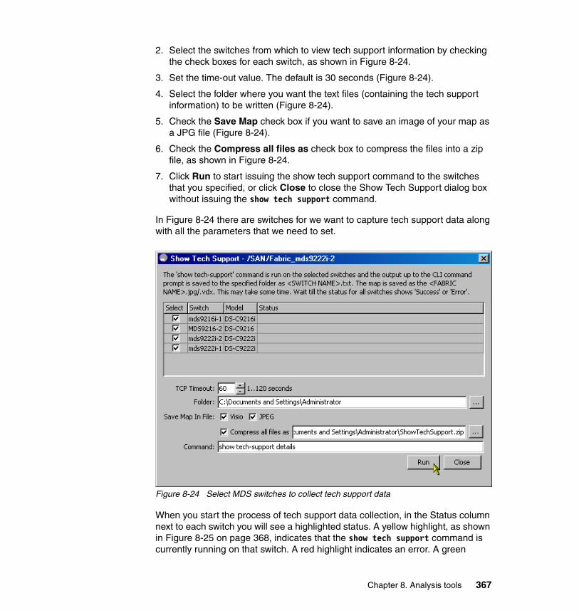
2. Select the switches from which to view tech support information by checking the check boxes for each switch, as shown in Figure 8-24.
3. Set the time-out value. The default is 30 seconds (Figure 8-24).
4. Select the folder where you want the text files (containing the tech support information) to be written (Figure 8-24).
5. Check the Save Map check box if you want to save an image of your map as a JPG file (Figure 8-24).
6. Check the Compress all files as check box to compress the files into a zip file, as shown in Figure 8-24.
7. Click Run to start issuing the show tech support command to the switches that you specified, or click Close to close the Show Tech Support dialog box without issuing the show tech support command.
In Figure 8-24 there are switches for we want to capture tech support data along with all the parameters that we need to set.
Figure 8-24 Select MDS switches to collect tech support data
When you start the process of tech support data collection, in the Status column next to each switch you will see a highlighted status. A yellow highlight, as shown in Figure 8-25 on page 368, indicates that the show tech support command is currently running on that switch. A red highlight indicates an error. A green
Chapter 8. Analysis tools 367

highlight, like the one shown in Figure 8-26 on page 369, indicates that the show tech support command has completed successfully.
Figure 8-25 shows the progress of the tech support data collection process.
Figure 8-25 Data collection is in progress
368 Implementing an IBM/Cisco SAN

Figure 8-26 shows that the tech support data collection process has finished successfully for all selected switches.
Figure 8-26 Data collection completed successfully
As shown in Figure 8-27, all tech support data from all mds switches in the fabric have been saved to a zip file along with images of the fabric map in the JPG and VXD format.
Figure 8-27 Tech support files saved into a ZIP file
Chapter 8. Analysis tools 369

A fabric map, as shown in Figure 8-28, could be useful to support experts in analysis and problem determination.
Figure 8-28 A fabric map as show tech support output
8.1.8 Cisco Fabric AnalyzerFibre Channel protocol analyzers capture, decode, and analyze frames and ordered sets on a link. Existing Fibre Channel analyzers can capture traffic at wire rate speed. They are also expensive and support limited frame decoding. Also, to snoop traffic, the existing analyzers disrupt the traffic on the link while the analyzer is inserted into the link. With the Cisco Fabric Analyzer you can capture Fibre Channel control traffic from a switch and decode it without having to disrupt any connectivity, and without having to be local to the point of analysis. The Cisco Fibre Channel protocol analyzer is based on two popular public-domain software applications:
� libpcap
http://www.tcpdump.org
� Wireshark (formerly Etherreal)
http://www.wireshark.org
370 Implementing an IBM/Cisco SAN

The Cisco Fabric Analyzer consists of two separate components:
� Software that runs on the Cisco MDS 9000 family switch and supports two modes of capture:
– A text-based analyzer that supports local capture and decodes captured frames
– A daemon that supports remote capture
� GUI-based client that runs on a host that supports libpcap, such as Windows or Linux, and communicates with the remote capture daemon in a Cisco MDS 9000 family switch.
Local text-based captureThis component is a command-line-driven text-based interface that captures traffic to and from the supervisor module in a Cisco MDS 9000 family switch. It is a fully functional decoder that is useful for quick debug purposes or for use when the remote capture daemon is not enabled. Additionally, because this tool is accessed from within the Cisco MDS 9000 family switch, it is protected by the roles-based policy that limits access in each switch.
Remote capture daemonThis daemon is the server end of the remote capture component. The Ethereal analyzer running on a host is the client end. They communicate with each other using the Remote Capture Protocol (RPCAP). RPCAP uses two endpoints:
� A TCP-based control connection � A TCP or UDP-based data connection based on TCP (default) or UDP.
The control connection is used to remotely control the captures (start or stop the capture, or specify capture filters). Remote capture can only be performed to explicitly configured hosts. This technique prevents an unauthorized machine in the network from snooping on the control traffic in the network.
RPCAP supports two setup connection modes based on firewall restrictions:
� Passive mode (default): The configured host initiates connection to the switch. Multiple hosts can be configured to be in passive mode and multiple hosts can be connected and receive remote captures at the same time.
� Active mode: The switch initiates the connection to a configured host, one host at a time.
Note: The Cisco Fabric Analyzer is useful for capturing and decoding control traffic, not data traffic. It is suitable for control path captures, and is not intended for high-speed data path captures.
Chapter 8. Analysis tools 371

Using capture filters, you can limit the amount of traffic that is sent to the client. Capture filters are specified at the client end (on Ethereal, not on the switch).
GUI-based clientThe Wireshark software (formerly Etherreal) runs on a host, such as a PC or workstation, and communicates with the remote capture daemon. This software is available in the public domain from:
http://www.wireshark.org
The Ethereal GUI front-end supports a rich interface such as a colorized display, graphical assists in defining filters, and specific frame searches. These features are documented on Ethereal’s Web site. While remote capture through Ethereal supports capturing and decoding Fibre Channel frames from a Cisco MDS 9000 family switch, the host running Ethereal does not require a Fibre Channel connection to the switch. The remote capture daemon running on the switch sends the captured frames over the out-of-band Ethernet management port. This capability allows you to capture and decode Fibre Channel frames from your desktop or mobile computer.
8.1.9 Monitoring network traffic using SPANThe Cisco MDS 9000 family provides a feature called the switch port analyzer (SPAN). The SPAN or SD_Ports allow us to monitor network traffic through the Fibre Channel interface.
Traffic through any Fibre Channel interface can be replicated to a special port called the SPAN destination port. Any Fibre Channel port in a switch can be configured as an SD_Port. When an interface is in SD_Port mode, it cannot be used for normal data traffic. You can attach a Fibre Channel analyzer to the SD_Port to monitor SPAN traffic.
372 Implementing an IBM/Cisco SAN

SD_Ports do not receive frames. They only transmit a copy of the SPAN source traffic. The SPAN feature is non-intrusive and does not affect switching of network traffic for any SPAN source port.
Note: RSPAN has all the features of SPAN in addition to support for source ports and destination ports distributed across multiple switches, allowing remote monitoring of multiple switches across your network.
The traffic for each RSPAN session is carried over a user-specified RSPAN VLAN that is dedicated for that RSPAN session in all participating switches. The SPAN traffic from the sources, which cannot be in the RSPAN VLAN, is switched to the RSPAN VLAN and then forwarded to destination ports configured in the RSPAN VLAN.
The traffic type for sources (ingress, egress, or both) in an RSPAN session can be different in different source switches, but is the same for all sources in each source switch for each RSPAN session. Do not configure any ports in an RSPAN VLAN except those selected to carry RSPAN traffic. Learning is disabled on the RSPAN VLAN.
Chapter 8. Analysis tools 373

An overview of the SPAN port is illustrated in Figure 8-29.
Figure 8-29 SPAN destination ports
374 Implementing an IBM/Cisco SAN
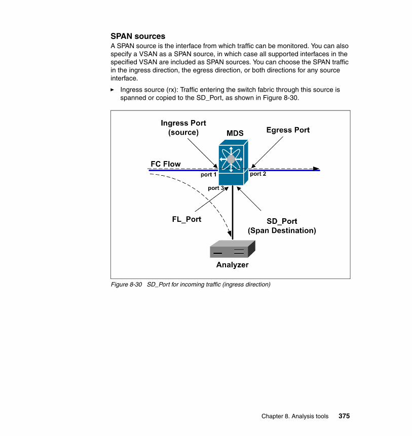
SPAN sourcesA SPAN source is the interface from which traffic can be monitored. You can also specify a VSAN as a SPAN source, in which case all supported interfaces in the specified VSAN are included as SPAN sources. You can choose the SPAN traffic in the ingress direction, the egress direction, or both directions for any source interface.
� Ingress source (rx): Traffic entering the switch fabric through this source is spanned or copied to the SD_Port, as shown in Figure 8-30.
Figure 8-30 SD_Port for incoming traffic (ingress direction)
Chapter 8. Analysis tools 375

� Egress source (tx): Traffic exiting the switch fabric through this source interface is spanned or copied to the SD_Port, as shown in Figure 8-31.
Figure 8-31 SD_Port for outgoing traffic (egress direction)
Allowed source interface typesThe SPAN feature is available for the following interface types:
� Physical ports:
– F_Ports
– FL_Ports
– TE_Ports
– E_Ports
– TL_Ports
� Interface sup-fc0 (traffic to and from the supervisor):
– The Fibre Channel traffic from the supervisor module to the switch fabric, through the sup-fc0 interface, is called ingress traffic. It is spanned when sup-fc0 is chosen as an ingress source port.
376 Implementing an IBM/Cisco SAN

– The Fibre Channel traffic from the switch fabric to the supervisor module, through the sup-fc0 interface, is called egress traffic. It is spanned when sup-fc0 is chosen as an egress source port.
� PortChannels:
– All ports in the PortChannel are included and spanned as sources.
– You cannot specify individual ports in a PortChannel as SPAN sources. Previously configured SPAN-specific interface information is discarded.
VSAN as a SPAN sourceWhen a VSAN is specified as a source, all physical ports and PortChannels in that VSAN are included as SPAN sources. A TE_Port is included only when the port VSAN of the TE_Port matches the SPAN source VSAN. A TE_Port is excluded even if the configured allowed VSAN list has the SPAN source VSAN, but the port VSAN configured for the PortChannel is different.
Guidelines for configuring VSANs as a sourceThe following guidelines apply when configuring VSANs as a source:
� Traffic on all interfaces included in a source VSAN is spanned only in the ingress direction.
� When a VSAN is specified as a source, you will not be able to perform interface-level configuration on the interfaces that are included in the VSAN. Previously configured SPAN-specific interface information is discarded.
� If an interface in a VSAN is configured as a SPAN source, you will not be able to configure that VSAN as a source. You must first remove the existing SPAN configurations on such interfaces before configuring VSAN as a source.
� Interfaces are only included as sources when the port VSAN matches the source VSAN.
SPAN sessionsEach SPAN session represents an association of one destination with a set of sources along with various other parameters that you specify to monitor the network traffic. One destination can be used by one or more SPAN sessions. You can configure up to 16 SPAN sessions in a switch. Each session can have several source ports and one destination port.
To activate a SPAN session, at least one source and the SD_Port must be up and functioning. Otherwise, traffic is not directed to the SD_Port.
To temporarily deactivate (suspend) a SPAN session use the suspend command in the SPAN submode. The traffic monitoring is stopped during this time. You can reactivate the SPAN session using the no suspend command.
Chapter 8. Analysis tools 377

Specifying filtersYou can perform VSAN-based filtering to selectively monitor network traffic on specified VSANs. You can apply this VSAN filter to the selected source or to all sources in a session. Only traffic in the selected VSANs is spanned when you configure VSAN filters. You can specify two types of VSAN filters:
� Interface-level filters: You can apply VSAN filters for a specified TE_Port or trunking PortChannel to filter traffic using one of three options:
– The ingress direction– The egress direction– Both directions
� Session filters: This option filters all sources in the specified session. These filters are bi-directional and apply to all sources configured in the session.
Guidelines for specifying filtersThe following guidelines apply to SPAN filters:
� Specify filters in the ingress direction or in the egress direction, or in both directions.
� PortChannel filters are applied to all ports in the PortChannel.
� If no filters are specified, the traffic from all active VSANs for that interface is spanned.
� The effective filter on a port is the intersection (filters common to both) of interface filters and session filters.
� While you can specify any arbitrary VSAN filters in an interface, traffic can only be monitored on the port VSAN or on allowed-active VSANs in that interface.
� When you configure VSAN as a source, that VSAN is implicitly applied as an interface filter to all sources included in the specified VSAN.
SD_Port characteristicsAn SD_Port has the following characteristics:
� It ignores buffer-to-buffer credits.
� It allows data traffic only in the egress (tx) direction.
� It does not require a device or an analyzer to be physically connected.
� It supports only 1 Gbps or 2 Gbps speeds. The auto speed option is not allowed.
� Multiple sessions can share the same destination ports.
� If the SD_Port is shut down, all shared sessions stop generating SPAN traffic.
378 Implementing an IBM/Cisco SAN

� The port mode cannot be changed if it is being used for a SPAN session.
� The outgoing frames can be encapsulated in EISL format.
� The SD_Port does not have a port VSAN.
The following guidelines apply for a SPAN configuration:
� You can configure up to 16 SPAN sessions with multiple ingress (rx) sources.
� You can configure a maximum of three SPAN sessions with one egress (tx) port.
� In a 32-port switching module you must configure the same session in all four ports in one port group. If you want, you can also configure only two or three ports in this unit.
� SPAN frames are dropped if the sum of the bandwidth of the sources exceeds the speed of the destination port.
� Frames dropped by a source port are not spanned.
In Figure 8-32 we show how to set FC1/14 as an SD port.
Figure 8-32 Set FC 1/14 port as SD
Chapter 8. Analysis tools 379

In Device Manager you can see that it is now an SD port, as shown in Figure 8-33.
Figure 8-33 FC1/14 is an SD port
You can configure an SD port from the CLI, as shown in Example 8-14.
Example 8-14 Configure an SD port from the CLI
mds9222i-2# configure terminalEnter configuration commands, one per line. End with CNTL/Z.mds9222i-2(config)# interface fc 1/14mds9222i-2(config-if)# switchport modeE F FL Fx NP SD ST TL automds9222i-2(config-if)# switchport mode SDmds9222i-2(config-if)# switchport speed1000 2000 4000 8000 automds9222i-2(config-if)# switchport speed 1000mds9222i-2(config-if)# switchport description Traffic_Analysismds9222i-2(config-if)# shutdownmds9222i-2(config-if)# no shutdownmds9222i-2(config-if)# endmds9222i-2# show interface fc 1/14fc1/14 is up Port description is Traffic_Analysis Hardware is Fibre Channel, SFP is short wave laser w/o OFC (SN) Port WWN is 20:0e:00:0d:ec:4a:c5:80 Admin port mode is SD snmp link state traps are enabled
380 Implementing an IBM/Cisco SAN

Port mode is SD Port vsan is 20 Speed is 1 Gbps Rate mode is shared Beacon is turned off 5 minutes input rate 88 bits/sec, 11 bytes/sec, 0 frames/sec 5 minutes output rate 64 bits/sec, 8 bytes/sec, 0 frames/sec 164 frames input, 8296 bytes 0 discards, 0 errors 0 CRC, 0 unknown class 0 too long, 0 too short 93 frames output, 6376 bytes 0 discards, 0 errors 2 input OLS, 2 LRR, 0 NOS, 2 loop inits 4 output OLS, 0 LRR, 0 NOS, 1 loop inits 1 receive B2B credit remaining 0 transmit B2B credit remaining 0 low priority transmit B2B credit remaining Interface last changed at Fri Sep 7 02:19:59 2007
8.1.10 Cisco Traffic Analyzer and Performance Manager
Performance Manager works in conjunction with Cisco Traffic Analyzer to monitor and manage the traffic on your fabric. Using Cisco Traffic Analyzer with Performance Manager requires the following components:
� A configured Fibre Channel Switched Port Analyzer (SPAN) destination (SD) port to forward Fibre Channel traffic.
� A Port Analyzer Adapter 2 (PAA-2) to convert the Fibre Channel traffic to Ethernet traffic.
� Cisco Traffic Analyzer software to analyze the traffic from the PAA-2.
Note: We recommend that you install Traffic Analyzer and Performance Manager on separate servers. We recommend a Linux server for installing Traffic Analyzer because of efficiency of resources allocation when analyzing extensive traffic.
Chapter 8. Analysis tools 381

Figure 8-34 shows how Performance Manager works with Cisco Traffic Analyzer to monitor traffic on your fabric.
Figure 8-34 Performance manager working with Cisco Traffic Analyzer
Port Analyzer Adapter 2 (PAA-2)The PAA-2 enables effective, low-cost analysis of Fibre Channel traffic. The device is a standalone Fibre Channel-to-Ethernet adapter, designed primarily to analyze SPAN traffic from a Fibre Channel port on a Cisco MDS 9000 family switch. The main function of the Port Analyzer Adapter 2 is to encapsulate Fibre Channel frames into Ethernet frames. This allows low-cost analysis of Fibre Channel traffic while leveraging the existing Ethernet infrastructure.
The PAA-2 allows you to examine Fibre Channel frames of various sizes. Fibre Channel frames from layers 2, 3, and 4 may be examined without network disruption.
Cisco Traffic AnalyzerPerformance Manager collects Fibre Channel level performance statistics using SNMP to access counters on Cisco MDS 9000 family switches. To view detailed SCSI I/O statistics, look at the data on an SD port with the help of the Cisco Traffic Analyzer, which uses the Cisco Port Analyzer Adapter 2 (PAA-2).
Cisco Traffic Analyzer provides real-time analysis of SPAN traffic or analysis of captured traffic through a Web browser user interface. Traffic encapsulated by one or more Port Analyzer Adapter 2 products can be analyzed concurrently with a single workstation running Cisco Traffic Analyzer, which is based on ntop (a
382 Implementing an IBM/Cisco SAN

network traffic probe), a public domain software enhanced by Cisco for Fibre Channel traffic analysis.
Round-trip response times, SCSI I/Os per second, SCSI read or traffic throughput and frame counts, SCSI session status, and management task information are monitored. Additional statistics are also available on Fibre Channel frame sizes and network management protocols.
For seamless performance analysis and troubleshooting, Cisco Traffic Analyzer can be launched in-context from Fabric Manager. Port world wide name, Fibre Channel ID (FC ID), FC alias, and VSAN names are passed to Cisco Traffic Analyzer.
Cisco Traffic Analyzer must be downloaded and installed separately from the following Web site:
http://www.cisco.com/kobayashi/sw-center/sw-stornet.shtml
Cisco Traffic Analyzer software is available under the Port Analyzer Adapter link.
8.1.11 Traffic Analyzer in Fabric Manager Web Server
Fabric Manager supports discovering instances of Traffic Analyzer and SPAN ports configured within your fabric.
Fabric Manager Web Server supports the following Traffic Analyzer integration features:
� SCSI I/O Traffic Analyzer pages can be viewed within the Web client.
� Traffic Analyzer can reside on a different server from Performance Manager.
� Performance Manager integrates with multiple servers running Traffic Analyzer.
� Instances of Traffic Analyzer servers can be discovered by Fabric Manager Server.
� The Web client report lists SPAN destination ports and associations with Traffic Analyzers.
Chapter 8. Analysis tools 383

Figure 8-35 shows Traffic Analyzer in the Fabric Manager Web Server.
Figure 8-35 Traffic Analyzer in Fabric Manager Web Server
8.1.12 System message loggingThe system message logging software saves messages in a log file or directs the messages to other devices. This feature provides you with the following capabilities:
� It provides logging information for monitoring and troubleshooting.
� It allows you to select the types of captured logging information.
� It allows you to select the destination server to forward the captured logging information.
By default, the switch logs normal but significant system messages to a log file and sends these messages to the system console. You can specify which system messages should be saved based on the type of facility and the severity level. Messages are time-stamped to enhance real-time debugging and management.
You can access logged system messages using the CLI or by saving them to a properly configured system message logging server. The switch software saves system messages in a file that can be configured to save up to 4 MB. You can monitor system messages remotely by accessing the switch through Telnet, SSH, or the console port, or by viewing the logs on a system message logging server.
384 Implementing an IBM/Cisco SAN

Use the show logging command to display the current system message logging configuration. In Table 8-1 there are some examples of logging commands and, in the interests of brevity, outputs are omitted.
Table 8-1 Show logging commands
8.1.13 Call HomeCall Home provides an e-mail-based notification of critical system events. A versatile range of message formats is available for optimal compatibility with pager services, standard e-mail, or XML-based automated parsing applications.
Common uses of this feature can include direct paging of a network support engineer, e-mail notification to a network operations center, and utilization of Cisco AutoNotify services for direct case generation with the technical assistance center.
The Call Home feature provides message throttling capabilities. Periodic inventory messages, port syslog messages, and RMON alert messages are added to the list of deliverable Call Home messages. If required, you can also use the Cisco Fabric Services application to distribute the Call Home configuration to all other switches in the fabric.
Show command Description
show logging nvram Displays NVRM log contents
show logging logfile Displays the log file
show logging console Displays the console logging status
show logging level Displays the logging facility
show logging info Displays logging information
show logging last 2 Displays the last two lines of a log file
show logging monitor Displays monitor logging status
show logging server Displays server information
show logging module Displays switching module logging status
Chapter 8. Analysis tools 385

You can configure the call home functionality using a callhome command in EXEC mode from the CLI. After the configuration is done you can check it, as shown in Example 8-15.
Example 8-15 CallHome example configuration
mds9222i-1# configure terminalmds9222i-1(config)# snmp-server contact Jacomds9222i-1(config)# callhomemds9222i-1(config-callhome)# email-contact [email protected](config-callhome)# phone-contact +123-321-123-321mds9222i-1(config-callhome)# streetaddress TrackMe 911mds9222i-1(config-callhome)# site-id BlueBusinessParkmds9222i-1(config-callhome)# customer-id BraveOnemds9222i-1(config-callhome)# contract-id ABC12345mds9222i-1(config-callhome)# distributemds9222i-1(config-callhome)# enablemds9222i-1(config-callhome)# endmds9222i-1# show callhomecallhome enabledCallhome Information:contact person name(sysContact):Jacocontact person's email:[email protected] person's phone number:+123-321-123-321street addr:TrackMe 911site id:BlueBusinessParkcustomer id:BraveOnecontract id:ABC12345switch priority:7duplicate message throttling : enabledperiodic inventory : enabledperiodic inventory time-period : 7 daysperiodic inventory timeofday : 08:00 (HH:MM)Distribution : Enabled
8.2 Performance Manager
Performance Manager gathers network device statistics historically and provides this information graphically using a Web browser. It presents recent statistics in detail and older statistics in summary. Performance Manager also integrates with external tools such as Cisco Traffic Analyzer.
386 Implementing an IBM/Cisco SAN

The Performance Manager has three operational stages:
� Definition: The Flow Wizard sets up flows in the switches.
� Collection: The Web Server Performance Collection panel collects information about desired fabrics.
� Presentation: Generates Web pages to present the collected data through Fabric Manager Web Server.
Performance Manager can collect statistics for ISLs, hosts, storage elements, and configured flows. Flows are defined based on a host-to-storage (or storage-to-host) link. Performance Manager gathers statistics from across the fabric based on collection configuration files. These files determine which SAN elements and SAN links Performance Manager gathers statistics for. Based on this configuration, Performance Manager communicates with the appropriate devices (switches, hosts, or storage elements) and collects the appropriate information at fixed five-minute intervals.
Performance Manager uses a round-robin database to hold the statistical data collected from the fabric. This data is stored based on the configured parameters in the collection configuration file. At each polling interval, Performance Manager gathers the relevant statistics and stores them in the round-robin database. This database is a fixed size and will not grow beyond its preset limits.
Performance Manager creates a series of archived data to hold summarized information present in the real-time round-robin database. This archived data is used to generate daily, weekly, monthly, and yearly consolidated reports. In this way, Performance Manager maintains significant historical data without the cost of an ever-increasing database size.
Data interpolationOne of the unique features of Performance Manager is its ability to interpolate data when statistical polling results are missing or delayed. Other performance tools may store the missing data point as zero, but this can distort historical trending. Performance Manager interpolates the missing data point by comparing the data point that preceded the missing data and the data point stored in the polling interval after the missing data. This maintains the continuity of the performance information.
Chapter 8. Analysis tools 387

Data collectionOne year’s worth of data for two variables (Rx and Tx bytes) requires a round-robin database (rrd) file size of 76 K. If errors and discards are also collected, the rrd file size becomes 110 K. The default internal values are:
� 600 samples of 5 minutes (2 days and 2 hours)� 700 samples of 30 minutes (12.5 days)� 775 samples of 2 hours (50 days)� 300 samples of 1 day
A 1000-port SAN requires 110 MB for a year’s worth of historical data that includes errors and discards. If there were 20 switches in this SAN with equal distribution of fabric ports, about two to three SNMP packets per switch would be sent every 5 minutes for a total of about 100 request or response SNMP packets required to monitor the data.
Flows, because of their variable counter requests, are more difficult to predict storage space requirements for. But as a rule of thumb, each extra flow adds another 76 kB.
Performance thresholdsThe Performance Manager Configuration Wizard allows you to set up two thresholds that will trigger events when the monitored traffic exceeds the percent utilization configured. These event triggers can be set as either critical or warning events that are reported on the Fabric Manager Web client Events browser page.
Absolute value thresholds apply directly to the statistics gathered. These statistics, as a percent of the total link capacity, are compared to the percent utilization configured for the threshold type. If the statistics exceed either configured threshold, an event is shown on the Fabric Manager Web client Events tab.
Baseline thresholds create a threshold that adapts to the typical traffic pattern for each link for the same time window each day, week, or every two weeks. Baseline thresholds are set as a percent of the average (110% to 500%), where 100% equals the calculated weighted average.
Flow definitionThe Performance Manager Flow and Performance Manager Setup wizards greatly simplify configuration. All you need to do is select the categories of statistics to capture and the wizards provide a list of flows and links to monitor.
Note: Performance Manager does not collect statistics on non-manageable and non-MDS switches. Loop devices (FL/NL) are not collected.
388 Implementing an IBM/Cisco SAN

You can remove entries if desired, or just accept the provided list and start data collection. Statistics for host and storage links are not associated with a specific port on a switch, so you do not lose long-term statistics if a connection is moved to a different port.
To create a flow using Fabric Manager:
1. Choose Performance → Create Flow, as shown in Figure 8-36.
Figure 8-36 Define a Flow using the Fabric Manager
2. Specify a VSAN to define a flow and specify the type of traffic to capture data, as shown in Figure 8-37.
Figure 8-37 Define flow conditions
Chapter 8. Analysis tools 389

3. The Review Traffic Flows window displays all VSAN flow pairs in the existing flows for VSANs area. Select traffic pairs to create flows and select Add, as shown in Figure 8-38.
Figure 8-38 Add traffic pairs to flows for a specified VSAN
390 Implementing an IBM/Cisco SAN

4. When you have finished selecting traffic pairs and creating flows click Finish, as shown in Figure 8-39, to complete the flow definition.
Figure 8-39 Traffic flow definition completed
Chapter 8. Analysis tools 391
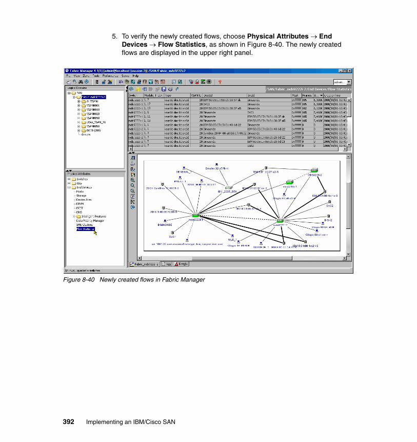
5. To verify the newly created flows, choose Physical Attributes → End Devices → Flow Statistics, as shown in Figure 8-40. The newly created flows are displayed in the upper right panel.
Figure 8-40 Newly created flows in Fabric Manager
392 Implementing an IBM/Cisco SAN

Glossary
8b/10b A data encoding scheme developed by IBM, translating byte-wide data to an encoded 10-bit format. The Fibre Channel (FC) FC-1 level defines this as the method to use to encode and decode data transmissions over the Fibre Channel.
active configuration In an ESCON® environment, the ESCON Director configuration determined by the status of the current set of connectivity attributes. Contrast with saved configuration.
adapter A hardware unit that aggregates other input/output (I/O) units, devices, or communications links to a system bus.
ADSM ADSTAR Distributed Storage Manager.
Advanced Intelligent Tape (AIT) A magnetic tape format by Sony that uses 8 mm cassettes, but is only used in specific drives.
agent In the client-server model, the part of the system that performs information preparation and exchange on behalf of a client or server application. In the Simple Network Management Protocol (SNMP), the managed system. See also management agent.
aggregation In the Storage Networking Industry Association Storage Model (SNIA), virtualization is known as aggregation. This aggregation can take place at the file level or at the level of individual blocks that are transferred to disk.
AIT See Advanced Intelligent Tape.
AL See arbitrated loop.
allowed In an ESCON Director, the attribute that, when set, establishes dynamic connectivity capability. Contrast with prohibited.
© Copyright IBM Corp. 2009. All rights reserved.
AL_PA Arbitrated Loop Physical Address.
American National Standards Institute (ANSI) The primary organization for fostering the development of technology standards in the United States. The ANSI family of Fibre Channel documents provides the standards basis for the Fibre Channel architecture and technology. See also FC-PH.
ANSI See American National Standards Institute.
APAR See authorized program analysis report.
arbitrated loop (AL) A Fibre Channel interconnection technology that allows up to 126 participating node ports and one participating fabric port to communicate.
arbitration The process of selecting one respondent from a collection of several candidates that request service concurrently.
Asynchronous Transfer Mode (ATM) A type of packet switching that transmits fixed-length units of data.
ATL See Automated Tape Library.
ATM See Asynchronous Transfer Mode.
authorized program analysis report (APAR) A report of a problem caused by a suspected defect in a current, unaltered release of a program.
Automated Tape Library (ATL) Large-scale tape storage system that uses multiple tape drives and mechanisms to address 50 or more cassettes.
backup A copy of computer data, or the act of copying such data, that is used to recreate data that has been lost, mislaid, corrupted, or erased.
bandwidth A measure of the information capacity
393

of a transmission channel.
basic mode An S/390® or IBM eServer™ zSeries® central processing mode that does not use logical partitioning. Contrast with logically partitioned mode.
blocked In an ESCON and FICON Director, the attribute that, when set, removes the communication capability of a specific port. Contrast with unblocked.
bridge A component used to attach more than one I/O unit to a port. Also a data communications device that connects two or more networks and forwards packets between them. The bridge may use similar or dissimilar media and signaling systems. It operates at the data link level of the OSI model. Bridges read and filter data packets and frames.
bridge/router A device that can provide the functions of a bridge, router, or both, concurrently. A bridge/router can route one or more protocols, such as TCP/IP, and bridge all other traffic. See also bridge and router.
broadcast To send a transmission to all N_Ports on a fabric.
byte 1) In Fibre Channel, an 8-bit entity prior to encoding or after decoding, with its least significant bit denoted as bit 0 and most significant bit as bit 7. The most significant bit is shown on the left side in FC-FS unless otherwise shown. 2) In S/390 architecture or z/Architecture® for zSeries (and FICON), an 8-bit entity prior to encoding or after decoding, with its least significant bit denoted as bit 7 and most significant bit as bit 0. The most significant bit is shown on the left side in S/390 architecture and z/Architecture for zSeries.
cascaded switches The connecting of one Fibre Channel switch to another Fibre Channel switch, creating a cascaded switch route between two N_Nodes connected to a Fibre Channel fabric.
chained In an ESCON environment, pertaining to the physical attachment of two ESCON Directors (ESCDs) to each other.
channel 1) A processor system element that controls one channel path, whose mode of operation depends on the type of hardware to which it is attached. In a channel subsystem, each channel controls an I/O interface between the channel control element and the logically attached control units. 2) In ESA/390 or z/Architecture, the part of a channel subsystem that manages a single I/O interface between a channel subsystem and a set of controllers (control units).
channel to channel See CTC.
channel to converter See CVC.
channel-attached Devices attached directly by data channels (I/O channels) to a computer. Also refers to devices attached to a controlling unit by cables rather than by telecommunication lines.
channel I/O A form of I/O where request and response correlation is maintained through a form of source, destination, and request identification.
channel path (CHP) A single interface between a central processor and one or more control units along which signals and data can be sent to perform I/O requests.
channel path identifier (CHPID) In a channel subsystem, a value assigned to each installed channel path of the system that uniquely identifies that path to the system.
channel subsystem (CSS) Relieves the processor of direct I/O communication tasks and performs path management functions. Uses a collection of subchannels to direct a channel to control the flow of information between I/O devices and main storage.
CHP See channel path.
CHPID See channel path identifier.
CIFS Common Internet File System.
394 Implementing an IBM/Cisco SAN

cladding In an optical cable, the region of low refractive index surrounding the core. See also core and optical fiber.
Class of Service A Fibre Channel frame delivery scheme that exhibits a specified set of delivery characteristics and attributes.
Class-1 A class of service that provides dedicated connection between two ports with confirmed delivery or notification of nondeliverability.
Class-2 A class of service that provides a frame-switching service between two ports with confirmed delivery or notification of nondeliverability.
Class-3 A class of service that provides frame-switching datagram service between two ports or a multicast service between a multicast originator and one or more multicast recipients.
Class-4 A class of service that provides a fractional bandwidth virtual circuit between two ports with confirmed delivery or notification of nondeliverability.
Class-6 A class of service that provides a multicast connection between a multicast originator and one or more multicast recipients with confirmed delivery or notification of nondeliverability.
client A software program used to contact and obtain data from a server software program on another computer, often across a great distance. Each client program is designed to work specifically with one or more kinds of server programs, and each server requires a specific kind of client program.
client/server The relationship between machines in a communications network. The client is the requesting machine and the server is the supplying machine. Also used to describe the information management relationship between software components in a processing system.
cluster A type of parallel or distributed system that consists of a collection of interconnected whole computers and is used as a single, unified computing resource.
CNC A mnemonic for an ESCON channel used to communicate to an ESCON-capable device.
coaxial cable A transmission media (cable) used for high-speed transmission. It is called coaxial because it includes one physical channel that carries the signal surrounded (after a layer of insulation) by another concentric physical channel, both of which run along the same axis. The inner channel carries the signal and the outer channel serves as a ground.
configuration matrix In an ESCON environment or FICON, an array of connectivity attributes that appear as rows and columns on a display device and can be used to determine or change active and saved ESCON or FICON director configurations.
connected In an ESCON Director, the attribute that, when set, establishes a dedicated connection between two ESCON ports. Contrast with disconnected.
connection In an ESCON Director, an association established between two ports that provides a physical communication path between them.
connectivity attribute In an ESCON and FICON Director, the characteristic that determines a particular element of a port's status. See allowed, prohibited, blocked, unblocked, as well as connected and disconnected.
control unit A hardware unit that controls the reading, writing, or displaying of data at one or more I/O units.
controller A component that attaches to the system topology through a channel semantic protocol that includes some form of request/response identification.
core In an optical cable, the central region of an optical fiber through which light is transmitted and that has an index of refraction greater than the surrounding cladding material. See also cladding and optical fiber.
Glossary 395

coupler In an ESCON environment, link hardware used to join optical fiber connectors of the same type. Contrast with adapter.
CRC See Cyclic Redundancy Check.
CSS See channel subsystem.
CTC Channel-to-channel. A mnemonic for an ESCON channel attached to another ESCON channel, where one of the two ESCON channels is defined as an ESCON CTC channel and the other ESCON channel is defined as a ESCON CNC channel. Also a mnemonic for a FICON channel supporting a CTC Control Unit function logically or physically connected to another FICON channel that also supports a CTC Control Unit function. FICON channels supporting the FICON CTC control unit function are defined as normal FICON native (FC) mode channels.
CVC A mnemonic for an ESCON channel attached to an IBM 9034 convertor. The 9034 converts ESCON CVC signals to parallel channel interface (OEMI) communication operating in block multiplex mode (Bus and Tag).
Cyclic Redundancy Check (CRC) An error-correcting code used in Fibre Channel.
DASD See direct access storage device.
DAT See Digital Audio Tape.
data sharing A SAN solution in which files on a storage device are shared between multiple hosts.
datagram Refers to the Class 3 Fibre Channel Service that allows data to be sent rapidly to multiple devices attached to the fabric, with no confirmation of delivery.
DDM See disk drive module.
dedicated connection In an ESCON Director, a connection between two ports that is not affected by information contained in the transmission frames. This connection, which restricts those ports from communicating with any other port, can be
established or removed only as a result of actions performed by a host control program or at the ESCD console. Contrast with dynamic connection.
default Pertaining to an attribute, value, or option that is assumed when none is explicitly specified.
Dense Wavelength Division Multiplexing (DWDM) The concept of packing multiple signals tightly together in separate groups, and transmitting them simultaneously over a common carrier wave.
destination Any point or location, such as a node, station, or a particular terminal, to which information is to be sent. An example is a Fibre Channel fabric F_Port; when attached to a Fibre Channel N_port, communication to the N_port via the F_port is said to be to the F_Port destination identifier (D_ID).
device A mechanical, electrical, or electronic contrivance with a specific purpose.
device address 1) In ESA/390 architecture and z/Architecture for zSeries, the field of an ESCON device-level frame that selects a specific device on a control unit image. 2) In the FICON channel FC-SB-2 architecture, the device address field in an SB-2 header that is used to select a specific device on a control unit image.
device number 1) In ESA/390 and z/Architecture for zSeries, a four-hexadecimal character identifier (for example, 19A0) that you associate with a device to facilitate communication between the program and the host operator. 2) The device number that you associate with a subchannel that uniquely identifies an I/O device.
dB Decibel. A ratio measurement distinguishing the percentage of signal attenuation (loss) between the I/O power. Attenuation is expressed as dB/km.
Digital Audio Tape (DAT) A tape media technology designed for very high quality audio recording and data backup. DAT cartridges look like
Note: The two links having a dedicated connection appear as one continuous link.
396 Implementing an IBM/Cisco SAN

audio cassettes and are often used in mechanical auto-loaders. Typically, a DAT cartridge provides 2 GB of storage, but new DAT systems have much larger capacities.
Digital Linear Tape (DLT) A magnetic tape technology originally developed by Digital Equipment Corporation (DEC) and now sold by Quantum. DLT cartridges provide storage capacities from 10 GB to 35 GB.
direct access storage device (DASD) A mass storage medium on which a computer stores data. any online storage device: a disc, drive or CD-ROM.
disconnected In an ESCON Director, the attribute that, when set, removes a dedicated connection. Contrast with connected.
disk A mass storage medium on which a computer stores data.
disk drive module (DDM) A disk storage medium that you use for any host data that is stored within a disk subsystem.
disk mirroring A fault-tolerant technique that writes data simultaneously to two hard disks using the same hard disk controller.
disk pooling A SAN solution in which disk storage resources are pooled across multiple hosts rather than dedicated to a specific host.
distribution panel In an ESCON and FICON environment, a panel that provides a central location for the attachment of trunk and jumper cables and can be mounted in a rack, wiring closet, or on a wall.
DLT See Digital Linear Tape.
duplex Pertaining to communication in which data or control information can be sent and received at the same time, from the same node. Contrast with half duplex.
duplex connector In an ESCON environment, an optical fiber component that terminates both jumper cable fibers in one housing and provides physical keying for attachment to a duplex receptacle.
duplex receptacle In an ESCON environment, a fixed or stationary optical fiber component that provides a keyed attachment method for a duplex connector.
DWDM See Dense Wavelength Division Multiplexing.
dynamic connection In an ESCON Director, a connection between two ports, established or removed by the ESCD and that, when active, appears as one continuous link. The duration of the connection depends on the protocol defined for the frames transmitted through the ports and on the state of the ports. Contrast with dedicated connection.
dynamic connectivity In an ESCON Director, the capability that allows connections to be established and removed at any time.
Dynamic I/O Reconfiguration An S/390 and z/Architecture function that allows I/O configuration changes to be made nondisruptively to the current operating I/O configuration.
ECL See Emitter Coupled Logic.
ELS See Extended Link Services.
EMIF See ESCON Multiple Image Facility.
Emitter Coupled Logic (ECL) The type of transmitter used to drive copper media such as Twinax, Shielded Twisted Pair, or Coax.
enterprise network A geographically dispersed network under the auspices of one organization.
Enterprise Systems Architecture/390 (ESA/390) An IBM architecture for mainframe computers and peripherals. Processors that follow this architecture include the S/390 Server family of processors.
Glossary 397

Enterprise System Connection (ESCON) 1) An ESA/390 computer peripheral interface. The I/O interface uses ESA/390 logical protocols over a serial interface that configures attached units to a communication fabric. 2) A set of IBM products and services that provide a dynamically connected environment within an enterprise.
entity In general, a real or existing object from the Latin ens, or being, which makes the distinction between an object’s existence and its qualities. In programming, engineering and probably many other contexts, the word is used to identify units, whether concrete items or abstract ideas, that have no ready name or label.
E_Port Expansion Port. A port on a switch used to link multiple switches together into a Fibre Channel switch fabric.
ESA/390 See Enterprise Systems Architecture/390.
ESCD Enterprise Systems Connection (ESCON) Director.
ESCD console The ESCON Director display and keyboard device used to perform operator and service tasks at the ESCD.
ESCON See Enterprise System Connection.
ESCON channel A channel having an Enterprise Systems Connection channel-to-control-unit I/O interface that uses optical cables as a transmission medium. May operate in CBY, CNC, CTC or CVC mode. Contrast with parallel channel.
ESCON Director An I/O interface switch that provides the interconnection capability of multiple ESCON interfaces (or FICON Bridge (FCV) mode - 9032-5) in a distributed-star topology.
ESCON Multiple Image Facility (EMIF) In the ESA/390 architecture and z/Architecture for zSeries, a function that allows logical partitions (LPARs) to share an ESCON and FICON channel path (and other channel types) by providing each LPAR with its own channel-subsystem image.
exchange A group of sequences which share a unique identifier. All sequences within a given exchange use the same protocol. Frames from multiple sequences can be multiplexed to prevent a single exchange from consuming all the bandwidth. See also sequence.
Extended Link Services (ELS) Via a command request, solicits a destination port (N_Port or F_Port) to perform a function or service. Each ELS request consists of an Link Service (LS) command; the N_Port ELS commands are defined in the FC-FS architecture.
fabric Fibre Channel employs a fabric to connect devices. A fabric can be as simple as a single cable connecting two devices. The term is most often used to describe a more complex network using hubs, switches, and gateways.
Fabric Login (FLOGI) Used by an N_Port to determine if a fabric is present and, if so, to initiate a session with the fabric by exchanging service parameters with the fabric. Fabric Login is performed by an N_Port following link initialization and before communication with other N_Ports is attempted.
Fabric Shortest Path First (FSPF) An intelligent path selection and routing standard and is part of the Fibre Channel Protocol.
FC 1) A short form when referring to something that is part of the Fibre Channel standard. Used by the IBM I/O definition process when defining a FICON channel (using IOCP of HCD) that will be used in FICON native mode (using the FC-SB-2 communication protocol. See also Fibre Channel.
FC-0 Lowest level of the Fibre Channel Physical standard, covering the physical characteristics of the interface and media.
FC-1 Middle level of the Fibre Channel Physical standard, defining the 8b/10b encoding and decoding and transmission protocol.
398 Implementing an IBM/Cisco SAN

FC-2 Highest level of the Fibre Channel Physical standard, defining the rules for signaling protocol and describing transfer of frame, sequence, and exchanges.
FC-3 The hierarchical level in the Fibre Channel standard that provides common services such as striping definition.
FC-4 The hierarchical level in the Fibre Channel standard that specifies the mapping of upper-layer protocols to levels below.
FCA See Fibre Channel Association.
FC-AL See Fibre Channel Arbitrated Loop.
FC-CT Fibre Channel Common Transport Protocol
FC-FG See Fibre Channel Fabric Generic.
FC-FP See Fibre Channel HIPPI Framing Protocol.
FC-FS See Fibre Channel-Framing and Signaling.
FC-GS See Fibre Channel Generic Services.
FCLC See Fibre Channel Loop Association.
FC-LE See Fibre Channel Link Encapsulation.
FCP See Fibre Channel Protocol.
FC-PH See Fibre Channel Physical and Signaling.
FC-PLDA Fibre Channel Private Loop Direct Attach. See Private Loop Direct Attach.
FCS See Fibre Channel standard.
FC-SB See Fibre Channel Single Byte Command Code Set.
FC Storage Director SAN Storage Director.
FC-SW See Fibre Channel Switch Fabric.
fiber See optical fiber.
Fibre Channel A technology for transmitting data between computer devices at a data rate of up to 4 Gbps. It is especially suited for connecting computer servers to shared storage devices and for interconnecting storage controllers and drives.
Fibre Channel Arbitrated Loop (FC-AL) A reference to the FC-AL standard, a shared gigabit media for up to 127 nodes, one of which may be attached to a switch fabric. See also arbitrated loop.
Fibre Channel Association (FCA) A Fibre Channel industry association that works to promote awareness and understanding of the Fibre Channel technology and its application, and provides a means for implementers to support the standards committee activities.
Fibre Channel Fabric Generic (FC-FG) A reference to the document (ANSI X3.289-1996) which defines the concepts, behavior, and characteristics of the Fibre Channel fabric along with suggested partitioning of the 24-bit address space to facilitate the routing of frames.
Fibre Channel-Framing and Signaling (FC-FS) The term used to describe the FC-FS architecture.
Fibre Channel Generic Services (FC-GS) A reference to the document (ANSI X3.289-1996) that describes a common transport protocol used to communicate with the server functions, a full X500-based directory service, mapping of the SNMP directly to the Fibre Channel, a time server, and an alias server.
Fibre Channel HIPPI Framing Protocol (FCFP) A reference to the document (ANSI X3.254-1994) that defines how the HIPPI framing protocol is transported via the Fibre Channel.
Fibre Channel Link Encapsulation (FC-LE) A reference to the document (ANSI X3.287-1996) which defines how IEEE 802.2 Logical Link Control (LLC) information is transported via the Fibre Channel.
Glossary 399

Fibre Channel Loop Association (FCLC) An independent working group of the FCA focused on the marketing aspects of the Fibre Channel loop technology.
Fibre Channel Physical and Signaling (FC-PH) A reference to the ANSI X3.230 standard, that contains the definition of the three lower levels (FC-0, FC-1, and FC-2) of the Fibre Channel.
Fibre Channel Protocol (FCP) The mapping of SCSI-3 operations to Fibre Channel.
Fibre Channel Service Protocol (FSP) The common FC-4 level protocol for all services, transparent to the fabric type or topology.
Fibre Channel Single Byte Command Code Set (FC-SB) A reference to the document (ANSI X.271-1996) which defines how the ESCON command set protocol is transported using the Fibre Channel.
Fibre Channel standard (FCS) An ANSI standard for a computer peripheral interface. The I/O interface defines a protocol for communication over a serial interface that configures attached units to a communication fabric. The protocol has four layers. The lower of the four layers defines the physical media and interface, the upper of the four layers defines one or more Upper Layer Protocols (ULP), for example, FCP for SCSI command protocols and FC-SB-2 for FICON protocol supported by ESA/390 and z/Architecture. Refer to ANSI X3.230.1999x.
Fibre Channel Switch Fabric (FC-SW) A reference to the ANSI standard under development that further defines the fabric behavior described in FC-FG and defines the communications between different fabric elements required for those elements to coordinate their operations and management address assignment.
fiber optic cable See optical cable.
fiber optics The branch of optical technology concerned with the transmission of radiant power through fibers made of transparent materials such as glass, fused silica, and plastic.
FICON 1) An ESA/390 and zSeries computer peripheral interface. The I/O interface uses ESA/390 and zSeries FICON protocols (FC-FS and FC-SB-2) over a Fibre Channel serial interface that configures attached units to a FICON supported Fibre Channel communication fabric. 2) An FC4 proposed standard that defines an effective mechanism for the export of the SBCCS-2 (FC-SB-2) command protocol via Fibre Channels.
FICON channel A channel having a Fibre Channel connection (FICON) channel-to-control-unit I/O interface that uses optical cables as a transmission medium. May operate in either FC or FCV mode.
FICON Director A Fibre Channel switch that supports the ESCON-like “control unit port” (CUP function) that is assigned a 24-bit Fibre Channel port address to allow FC-SB-2 addressing of the CUP function to perform command and data transfer. (In the Fibre Channel world, it is a means of in-band management using a FC-4 ULP.)
field replaceable unit (FRU) An assembly that is replaced in its entirety when any one of its required components fails.
F_Node Fabric Node. A fabric attached node.
FLOGI See Fabric Login.
F_Port Fabric Port. A port used to attach a Node Port (N_Port) to a switch fabric.
frame A linear set of transmitted bits that define the basic transport unit. The frame is the most basic element of a message in Fibre Channel communications, consisting of a 24-byte header and zero to 2112 bytes of data. See also sequence.
Note: Telecommunication applications of fiber optics use optical fibers. Either a single discrete fiber or a non-spatially aligned fiber bundle can be used for each information channel. Such fibers are often called “optical fibers” to differentiate them from fibers used in non-communication applications.
400 Implementing an IBM/Cisco SAN

FRU See field replaceable unit.
FSP See Fibre Channel Service Protocol.
FSPF See Fabric Shortest Path First.
full duplex A mode of communications allowing simultaneous transmission and reception of frames.
gateway A node on a network that interconnects two otherwise incompatible networks.
Gbps Gigabits per second. Also sometimes referred to as Gbps. In computing terms, it is approximately 1000000000 bits per second. Most precisely it is 1073741824 (1024 x 1024 x 1024) bits per second.
Gbps Gigabytes per second. Also sometimes referred to as Gbps. In computing terms, it is approximately 1000000000 bytes per second. Most precisely it is 1073741824 (1024 x 1024 x 1024) bytes per second.
GBIC See Gigabit Interface Converter.
Gigabit One billion bits or one thousand megabits.
Gigabit Interface Converter (GBIC) Industry standard transceivers for connection of Fibre Channel nodes to arbitrated loop hubs and fabric switches.
Gigabit Link Module (GLM) A generic Fibre Channel transceiver unit that integrates the key functions necessary for the installation of a Fibre channel media interface on most systems.
GLM See Gigabit Link Module.
G_Port Generic Port. A generic switch port that is either an F_Port or E_Port. The function is automatically determined during login.
half duplex In data communication, pertaining to transmission in only one direction at a time. Contrast with duplex.
hard disk drive Storage media within a storage server used to maintain information that the storage server requires. Also a mass storage medium for computers that is typically available as a fixed disk or a removable cartridge.
hardware The mechanical, magnetic, and electronic components of a system, such as computers, telephone switches, and terminals.
HBA Host bus adapter.
HCD Hardware configuration dialog.
HDA See head and disk assembly.
HDD See hard disk drive.
head and disk assembly (HDA) The portion of an HDD associated with the medium and the read/write head.
hierarchical storage management (HSM) A software and hardware system that moves files from disk to slower, less expensive storage media based on rules and observation of file activity. Modern HSM systems move files from magnetic disk to optical disk to magnetic tape.
High Performance Parallel Interface (HPPI) An ANSI standard that defines a channel that transfers data between CPUs and from a CPU to disk arrays and other peripherals.
HIPPI See High Performance Parallel Interface.
HMMP HyperMedia Management Protocol.
HMMS See HyperMedia Management Schema.
hop An Fibre Channel frame may travel from a switch to a director, a switch to a switch, or a director to a director, which in this case is one hop.
HSM See Hierarchical Storage Management.
hub A Fibre Channel device that connects nodes into a logical loop by using a physical star topology. Hubs will automatically recognize an active node
Glossary 401

and insert the node into the loop. A node that fails or is powered off is automatically removed from the loop.
hub topology See loop topology.
Hunt Group A set of associated N_Ports attached to a single node, assigned a special identifier that allows any frames containing this identifier to be routed to any available N_Port in the set.
HyperMedia Management Schema (HMMS) The definition of an implementation-independent, extensible, common data description/schema, that allows data from a variety of sources to be described and accessed in real time regardless of the source of the data. See also WEBM and HMMP.
ID See identifier.
identifier A unique name or address that identifies such items as programs, devices, or systems.
in-band signaling Signaling that is carried in the same channel as the information. Also referred to as in-band.
in-band virtualization An implementation in which the virtualization process takes place in the data path between servers and disk systems. The virtualization can be implemented as software running on servers or in dedicated engines.
information unit A unit of information defined by an FC-4 mapping. Information units are transferred as a Fibre Channel sequence.
initial program load (IPL) 1) The initialization procedure that causes an operating system to commence operation. 2) The process by which a configuration image is loaded into storage at the beginning of a work day or after a system malfunction. (3) The process of loading system programs and preparing a system to run jobs.
input/output (I/O) 1) Pertaining to a device whose parts can perform an input process and an output process at the same time. 2) Pertaining to a functional unit or channel involved in an input
process, output process, or both, concurrently or not, and to the data involved in such a process. (3) Pertaining to input, output, or both.
input/output configuration data set (IOCDS) The data set in the S/390 and zSeries processor (in the support element) that contains an I/O configuration definition built by the I/O configuration program (IOCP).
input/output configuration program (IOCP) An S/390 program that defines to a system the channels, I/O devices, paths to the I/O devices, and the addresses of the I/O devices. The output is normally written to a S/390 or zSeries IOCDS.
interface 1) A shared boundary between two functional units, defined by functional characteristics, signal characteristics, or other characteristics as appropriate. The concept includes the specification of the connection of two devices having different functions. 2) Hardware, software, or both, that link systems, programs, or devices.
intermix A mode of service defined by Fibre Channel that reserves the full Fibre Channel bandwidth for a dedicated Class 1 connection, but allows connection-less Class 2 traffic to share the link if the bandwidth is available.
Inter-Switch Link (ISL) An Fibre Channel connection between switches and directors.
I/O See input/output.
I/O configuration The collection of channel paths, control units, and I/O devices that attaches to the processor. This may also include channel switches (for example, an ESCON Director).
IOCDS See input/output configuration data set.
IOCP See input/output configuration control program.
402 Implementing an IBM/Cisco SAN

IODF The data set that contains the S/390 or zSeries I/O configuration definition file produced during the definition of the S/390 or zSeries I/O configuration by HCD. Used as a source for IPL, IOCP, and Dynamic I/O Reconfiguration.
IP Internet Protocol
IPI Intelligent Peripheral Interface
IPL See initial program load.
ISL See Inter-Switch Link.
isochronous transmission Data transmission which supports network-wide timing requirements. A typical application for isochronous transmission is a broadcast environment which needs information to be delivered at a predictable time.
JBOD Just a bunch of disks.
jukebox A device that holds multiple optical disks and one or more disk drives, and can swap disks in and out of the drive as needed.
jumper cable In an ESCON and FICON environment, an optical cable having two conductors that provide physical attachment between a channel and a distribution panel or an ESCON/FICON Director port or a control unit/device, between an ESCON/FICON Director port and a distribution panel or a control unit/device, or between a control unit/device and a distribution panel. Contrast with trunk cable.
LAN See local area network.
laser A device that produces optical radiation using a population inversion to provide light amplification by stimulated emission of radiation and (generally) an optical resonant cavity to provide positive feedback. Laser radiation can be highly coherent temporally, spatially, or both.
latency A measurement of the time it takes to send a frame between two locations.
LC Lucent Connector. A registered trademark of Lucent Technologies.
LCU See logical control unit.
LED See light emitting diode.
licensed internal code (LIC) Microcode that IBM does not sell as part of a machine, but instead, licenses it to the client. LIC is implemented in a part of storage that is not addressable by user programs. Some IBM products use it to implement functions as an alternate to hard-wire circuitry.
light emitting diode (LED) A semiconductor chip that gives off visible or infrared light when activated. Contrast with laser.
link 1) In an ESCON environment or FICON environment (Fibre Channel environment), the physical connection and transmission medium used between an optical transmitter and an optical receiver. A link consists of two conductors, one used for sending and the other for receiving, thereby providing a duplex communication path. 2) In an ESCON I/O interface, the physical connection and transmission medium used between a channel and a control unit, a channel and an ESCD, a control unit and an ESCD, or at times between two ESCDs. 3) In a FICON I/O interface, the physical connection and transmission medium used between a channel and a control unit, a channel and a FICON Director, a control unit and a Fibre Channel FICON Director, or at times between two Fibre Channels switches.
link address 1) On an ESCON interface, the portion of a source or destination address in a frame that ESCON uses to route a frame through an ESCON director. ESCON associates the link address with a specific switch port that is on the ESCON director. 2) On a FICON interface, the port address (1-byte link address), or domain and port address (2-byte link address) portion of a source (S_ID) or destination address (D_ID) in a Fibre Channel frame that the Fibre Channel switch uses to route a frame through a Fibre Channel switch or Fibre Channel switch fabric. See also port address.
Glossary 403

Link_Control_Facility A termination card that handles the logical and physical control of the Fibre Channel link for each mode of use.
LIP See loop initialization primitive sequence.
local area network (LAN) A computer network located in a user’s premises within a limited geographic area, usually not larger than a floor or small building. Transmissions within a LAN are mostly digital, carrying data among stations at rates usually above one Mbps.
logical control unit (LCU) A separately addressable control unit function within a physical control unit. Usually a physical control unit that supports several LCUs. For ESCON, the maximum number of LCUs that can be in a control unit (and addressed from the same ESCON fiber link) is 16. They are addressed from x’0’ to x’F’. For FICON architecture, the maximum number of LCUs that can be in a control unit (and addressed from the same FICON fibre link) is 256. They are addressed from x’00’ to x’FF’. For both ESCON and FICON, the actual number supported, and the LCU address value, is both processor- and control unit implementation-dependent.
logical partition (LPAR) A set of functions that create a programming environment that is defined by the ESA/390 architecture or z/Architecture for zSeries. The ESA/390 architecture or z/Architecture for zSeries uses the term LPAR when more than one LPAR is established on a processor. An LPAR is conceptually similar to a virtual machine environment except that the LPAR is a function of the processor. Also, LPAR does not depend on an operating system to create the virtual machine environment.
logical switch number (LSN) A two-digit number used by the IOCP to identify a specific ESCON or FICON Director. This number is separate from the director’s “switch device number” and, for FICON, it is separate from the director’s “Fibre Channel switch address”.
logically partitioned mode A central processor mode, available on the configuration frame when
using the PR/SM™ facility, that allows an operator to allocate processor hardware resources among LPARs. Contrast with basic mode.
login server An entity within the Fibre Channel fabric that receives and responds to login requests.
loop circuit A temporary point-to-point like path that allows bidirectional communications between loop-capable ports.
loop initialization primitive (LIP) sequence A special Fibre Channel sequence that is used to start loop initialization. Allows ports to establish their port addresses.
loop topology An interconnection structure in which each point has physical links to two neighbors resulting in a closed circuit. In a loop topology, the available bandwidth is shared.
LPAR See logical partition.
L_Port Loop Port. A node or fabric port capable of performing arbitrated loop functions and protocols. NL_Ports and FL_Ports are loop-capable ports.
LSN See logical switch number.
Lucent Connector (LC) A registered trademark of Lucent Technologies
LVD Low Voltage Differential.
management agent A process that exchanges a managed node's information with a management station.
managed node A computer, a storage system, a gateway, a media device such as a switch or hub, a control instrument, a software product such as an operating system or an accounting package, or a machine on a factory floor, such as a robot.
managed object A variable of a managed node. This variable contains one piece of information about the node. Each node can have several objects.
404 Implementing an IBM/Cisco SAN

Management Information Block (MIB) A formal description of a set of network objects that can be managed using the SNMP. The format is defined as part of SNMP and is a hierarchical structure of information relevant to a specific device, defined in object-oriented terminology as a collection of objects, relations, and operations among objects.
management station A host system that runs the management software.
MAR See Media Access Rules.
Mbps Megabits per second. Also sometimes referred to as MBps. In computing terms, it is approximately 1000000 bits per second. Most precisely it is 1048576 (1024 x 1024) bits per second.
MBps Megabytes per second. Also sometimes referred to as MBps. In computing terms, it is approximately 1000000 bytes per second. Most precisely it is 1048576 (1024 x 1024) bytes per second.
media Plural of medium. The physical environment through which transmission signals pass. Common media include copper and fiber optic cable.
Media Access Rules (MAR) Enable systems to self-configure themselves is a SAN environment.
Media Interface Adapter (MIA) Enables optic-based adapters to interface with copper-based devices, including adapters, hubs, and switches.
metadata server In Storage Tank™, servers that maintain information (metadata) about the data files and grant permission for application servers to communicate directly with disk systems.
meter Equal to 39.37 inches, or just slightly larger than a yard (36 inches)
MIA See Media Interface Adapter.
MIB See Management Information Block.
mirroring The process of writing data to two separate physical devices simultaneously.
MM Multi-Mode. See Multi-Mode Fiber.
MMF See Multi-Mode Fiber.
multicast Sending a copy of the same transmission from a single source device to multiple destination devices on a fabric. This includes sending to all N_Ports on a fabric (broadcast) or to only a subset of the N_Ports on a fabric (multicast).
Multi-Mode Fiber (MMF) In optical fiber technology, an optical fiber that is designed to carry multiple light rays or modes concurrently, each at a slightly different reflection angle within the optical core. Multi-Mode fiber transmission is used for relatively short distances because the modes tend to disperse over longer distances. See also Single-Mode Fiber.
multiplex The ability to intersperse data from multiple sources and destinations onto a single transmission medium. Refers to delivering a single transmission to multiple destination N_Ports.
name server Provides translation from a given node name to one or more associated N_Port identifiers.
NAS See Network Attached Storage.
ND See node descriptor.
NDMP Network Data Management Protocol
NED See node-element descriptor.
network An aggregation of interconnected nodes, workstations, file servers, and peripherals, with its own protocol that supports interaction.
Network Attached Storage (NAS) A term used to describe a technology where an integrated storage system is attached to a messaging network that uses common communications protocols, such as TCP/IP.
Glossary 405

Network File System (NFS) A distributed file system in UNIX developed by Sun Microsystems. It allows a set of computers to cooperatively access each other’s files in a transparent manner.
Network Management System (NMS) A system responsible for managing at least part of a network. NMSs communicate with agents to help keep track of network statistics and resources.
network topology Physical arrangement of nodes and interconnecting communications links in networks based on application requirements and geographical distribution of users.
NFS See Network File System.
NL_Port Node Loop Port. A node port that supports arbitrated loop devices.
NMS See Network Management System. A system responsible for managing at least part of a network. NMSs communicate with agents to help keep track of network statistics and resources.
node An entity with one or more N_Ports or NL_Ports.
node descriptor (ND) In an ESCON and FICON environment, a 32-byte field that describes a node, channel, ESCON Director or FICON Director port, or a control unit.
node-element descriptor (NED) In an ESCON and FICON environment, a 32-byte field that describes a node element, such as a disk (DASD) device.
non-blocking Indicates that the capabilities of a switch are such that the total number of available transmission paths is equal to the number of ports. Therefore, all ports can have simultaneous access through the switch.
Non-L_Port A Node or Fabric port that is not capable of performing the arbitrated loop functions and protocols. N_Ports and F_Ports are not loop-capable ports.
N_Port Node Port. A Fibre Channel-defined hardware entity at the end of a link which provides the mechanisms necessary to transport information units to or from another node.
N_Port Login (PLOGI) Allows two N_Ports to establish a session and exchange identities and service parameters. It is performed following completion of the FLOGI process and prior to the FC-4 level operations with the destination port. May be either explicit or implicit.
OEMI See original equipment manufacturer information.
open system A system whose characteristics comply with standards made available throughout the industry and that can be connected to other systems that comply with the same standards.
operation A term defined in FC-2 that refers to one of the Fibre Channel building blocks composed of one or more, possibly concurrent, exchanges.
optical cable A fiber, multiple fibers, or a fiber bundle in a structure built to meet optical, mechanical, and environmental specifications. See also jumper cable, optical cable assembly, and trunk cable.
optical cable assembly An optical cable that is connector-terminated. Generally, an optical cable that has been connector-terminated by a manufacturer and is ready for installation. See also jumper cable and optical cable.
optical fiber Any filament made of dialectic materials that guides light, regardless of its ability to send signals. See also fiber optics and optical waveguide.
optical fiber connector A hardware component that transfers optical power between two optical fibers or bundles and is designed to be repeatedly connected and disconnected.
406 Implementing an IBM/Cisco SAN

optical waveguide A structure capable of guiding optical power. In optical communications, generally a fiber designed to transmit optical signals. See optical fiber.
ordered set A Fibre Channel term referring to four 10 -bit characters (a combination of data and special characters) providing low-level link functions, such as frame demarcation and signaling between two ends of a link.
original equipment manufacturer information (OEMI) A reference to an IBM guideline for a computer peripheral interface. More specifically, it refers to IBM S/360™ and S/370™ Channel to Control Unit OEMI. The interface uses ESA/390 logical protocols over an I/O interface that configures attached units in a multi-drop bus environment. This OEMI interface is also supported by the zSeries 900 processors.
originator A Fibre Channel term referring to the initiating device.
out-of-band signaling Signaling that is separated from the channel carrying the information. Also referred to as out-of-band.
out-of-band virtualization An alternative type of virtualization in which servers communicate directly with disk systems under control of a virtualization function that is not involved in the data transfer.
parallel channel A channel having a System/360™ and System/370™ channel-to-control-unit I/O interface that uses bus and tag cables as a transmission medium. Contrast with ESCON channel.
path In a channel or communication network, any route between any two nodes. For ESCON and FICON, this is the route between the channel and the control unit/device, or sometimes from the operating system control block for the device and the device itself.
path group The ESA/390 and zSeries architecture (z/Architecture) term for a set of channel paths that are defined to a controller as being associated with
a single S/390 image. The channel paths are in a group state and are online to the host.
path-group identifier ESA/390 and z/Architecture term for the identifier that uniquely identifies a given LPAR. The path-group identifier is used in communication between the system image program and a device. The identifier associates the path group with one or more channel paths, defining these paths to the control unit as being associated with the same system image.
PCICC (IBM) PCI Cryptographic Coprocessor.
peripheral Any computer device that is not part of the essential computer (the processor, memory and data paths) but is situated relatively close by. A near synonym is I/O device.
petard A device that is small and sometimes explosive.
PLDA See Private Loop Direct Attach.
PLOGI See N_Port Login.
point-to-point topology An interconnection structure in which each point has physical links to only one neighbor resulting in a closed circuit. In point-to-point topology, the available bandwidth is dedicated.
policy-based management Management of data on the basis of business policies (for example, “all production database data must be backed up every day”), rather than technological considerations (for example, “all data stored on this disk system is protected by remote copy”).
port An access point for data entry or exit. A receptacle on a device to which a cable for another device is attached. See also duplex receptacle.
port address In an ESCON Director, an address used to specify port connectivity parameters and to assign link addresses for attached channels and control units. In a FICON director or Fibre Channel switch, it is the middle 8 bits of the full 24-bit Fibre Channel port address. This field is also referred to
Glossary 407

as the area field in the 24-bit Fibre Channel port address. See also link address.
port bypass circuit A circuit used in hubs and disk enclosures to automatically open or close the loop to add or remove nodes on the loop.
port card In an ESCON and FICON environment, a field-replaceable hardware component that provides the optomechanical attachment method for jumper cables and performs specific device-dependent logic functions.
port name In an ESCON or FICON Director, a user-defined symbolic name of 24 characters or less that identifies a particular port.
Private Loop Direct Attach (PLDA) A technical report which defines a subset of the relevant standards suitable for the operation of peripheral devices such as disks and tapes on a private loop.
Private NL_Port An NL_Port which does not attempt login with the fabric and only communicates with other NL Ports on the same loop.
processor complex A system configuration that consists of all the machines required for operation; for example, a processor unit, a processor controller, a system display, a service support display, and a power and coolant distribution unit.
program temporary fix (PTF) A temporary solution or bypass of a problem diagnosed by IBM in a current unaltered release of a program.
prohibited In an ESCON or FICON Director, the attribute that, when set, removes dynamic connectivity capability. Contrast with allowed.
protocol 1) A set of semantic and syntactic rules that determine the behavior of functional units in achieving communication. 2) In Fibre Channel, the meaning of, and sequencing rules for, requests and responses used for managing the switch or switch fabric, transferring data, and synchronizing states of Fibre Channel fabric components. 3) A specification for the format and relative timing of information exchanged between communicating parties.
PTF See program temporary fix.
Public NL_Port An NL_Port that attempts login with the fabric and can observe the rules of either public or private loop behavior. A public NL_Port may communicate with both private and public NL_Ports.
QoS See Quality of Service.
Quality of Service (QoS) A set of communications characteristics required by an application. Each QoS defines a specific transmission priority, level of route reliability, and security level.
Quick Loop A unique Fibre Channel topology that combines arbitrated loop and fabric topologies. It is an optional licensed product that allows arbitrated loops with private devices to be attached to a fabric.
RAID See Redundant Array of Inexpensive or Independent Disks.
RAID 0 Level 0 RAID support. Striping, no redundancy.
RAID 1 Level 1 RAID support. Mirroring, complete redundancy.
RAID 5 Level 5 RAID support. Striping with parity.
Redundant Array of Inexpensive or Independent Disks (RAID) A method of configuring multiple disk drives in a storage subsystem for high availability and high performance.
repeater A device that receives a signal on an electromagnetic or optical transmission medium, amplifies the signal, and then retransmits it along the next leg of the medium.
responder A Fibre Channel term referring to the answering device.
route The path that an ESCON frame takes from a channel through an ESCD to a control unit/device.
408 Implementing an IBM/Cisco SAN

router 1) A device that can decide which of several paths network traffic will follow based on some optimal metric. Routers forward packets from one network to another based on network-layer information. 2) A dedicated computer hardware or software package which manages the connection between two or more networks. See also bridge and bridge/router.
SAF-TE SCSI Accessed Fault-Tolerant Enclosures.
SAN See storage area network.
SAN See System Area Network.
SANSymphony In-band block-level virtualization software made by DataCore Software Corporation and resold by IBM.
saved configuration In an ESCON or FICON Director environment, a stored set of connectivity attributes whose values determine a configuration that can be used to replace all or part of the ESCD’s or FICON’s active configuration. Contrast with active configuration.
SC connector A fiber optic connector standardized by ANSI TIA/EIA-568A for use in structured wiring installations.
scalability The ability of a computer application or product (hardware or software) to continue to function because of a change in size or volume. For example, the ability to retain performance levels when adding additional processors, memory, and storage.
SCSI See Small Computer System Interface.
SCSI-3 SCSI-3 consists of a set of primary commands and additional specialized command sets to meet the needs of specific device types. The SCSI-3 command sets are used not only for the SCSI-3 parallel interface but for additional parallel and serial protocols, including Fibre Channel, Serial Bus Protocol (used with IEEE 1394 Firewire physical protocol), and the Serial Storage Protocol (SSP).
SCSI Enclosure Services (SES) ANSI SCSI-3 proposal that defines a command set for soliciting basic device status (temperature, fan speed, power supply status, etc.) from a storage enclosures.
SCSI-FCP The term used to refer to the ANSI Fibre Channel Protocol for SCSI document (X3.269-199x) that describes the FC-4 protocol mappings and the definition of how the SCSI protocol and command set are transported using a Fibre Channel interface.
SE See service element.
sequence A series of frames strung together in numbered order which can be transmitted over a Fibre Channel connection as a single operation. See also exchange.
SERDES Serializer Deserializer.
Serial Storage Architecture (SSA) A high speed serial loop-based interface developed as a high speed point-to-point connection for peripherals, particularly high speed storage arrays, RAID, and CD-ROM storage by IBM.
server A computer which is dedicated to one task.
service element (SE) A dedicated service processing unit used to service a S/390 machine (processor).
SES See SCSI Enclosure Services.
Simple Network Management Protocol (SNMP) The Internet network management protocol that provides a means to monitor and set network configuration and run-time parameters.
Single-Mode Fiber (SMF) In optical fiber technology, an optical fiber that is designed for the transmission of a single ray or mode of light as a carrier. It is a single light path used for long-distance signal transmission. See also Multi-Mode Fiber.
Small Computer System Interface (SCSI) 1) A set of evolving ANSI standard electronic interfaces that allow personal computers to communicate with
Glossary 409

peripheral hardware such as disk drives, tape drives, CD_ROM drives, printers, and scanners faster and more flexibly than previous interfaces.The interface uses a SCSI logical protocol over an I/O interface that configures attached targets and initiators in a multidrop bus topology. The following table identifies the major characteristics of the different SCSI versions.
SM Single Mode. See Single-Mode Fiber.
SMART Self Monitoring and Reporting Technology.
SMF See Single-Mode Fiber.
SNIA See Storage Networking Industry Association.
SN storage network. See also SAN.
SNMP See Simple Network Management Protocol.
SNMWG See Storage Network Management Working Group.
SSA See Serial Storage Architecture.
star The physical configuration used with hubs in which each user is connected by communications links radiating out of a central hub that handles all communications.
storage area network (SAN) A dedicated, centrally managed, secure information infrastructure, which enables any-to-any interconnection of servers and storage systems.
storage media The physical device onto which data is recorded. Magnetic tape, optical disks, and floppy disks are all storage media.
Storage Network Management Working Group (SNMWG) Chartered to identify, define, and support open standards needed to address the increased management requirements imposed by storage area network environments.
Storage Networking Industry Association (SNIA) A non-profit organization comprised of more than 77 companies and individuals in the storage industry.
Storage Tank An IBM file aggregation project that enables a pool of storage, and even individual files, to be shared by servers of different types. In this way, Storage Tank can greatly improve storage utilization and enables data sharing.
StorWatch Expert StorWatch applications that employ a three-tiered architecture that includes a management interface, a StorWatch manager and agents that run on the storage resource or resources being managed. Products employ a StorWatch database that can be used for saving key management data, such as capacity or performance metrics. Products also use the agents and analysis of storage data saved in the database to perform higher value functions including the reporting of capacity and performance over time (trends), configuration of multiple devices based on policies, monitoring of capacity and performance, automated responses to events or conditions, and storage related data mining.
SCSI
version
Sig
na
l ra
te
(MH
z)
Bu
sW
idth
(b
its
)
Ma
xim
um
DT
R
(MB
ps
)
Ma
xim
um
no
.
de
vic
es
Ma
xim
um
ca
ble
len
gth
(m
)
SCSI-1 5 8 5 7 6
SCSI-2 5 8 5 7 6
Wide SCSI-2 5 16 10 15 6
Fast SCSI-2 10 8 10 7 6
Fast Wide SCSI-2 10 16 20 15 6
Ultra™ SCSI 20 8 20 7 1.5
Ultra SCSI-2 20 16 40 7 12
Ultra2 LVD SCSI 40 16 80 15 12
410 Implementing an IBM/Cisco SAN

StorWatch Specialist A StorWatch interface for managing an individual Fibre Channel device or a limited number of like devices (that can be viewed as a single group). Typically provide simple, point-in-time management functions such as configuration, reporting on asset and status information, simple device and event monitoring, and some service utilities.
STP Shielded Twisted Pair.
striping A method for achieving higher bandwidth using multiple N_Ports in parallel to transmit a single information unit across multiple levels.
subchannel A logical function of a channel subsystem associated with the management of a single device.
subsystem A secondary or subordinate system, or programming support, usually capable of operating independently of or asynchronously with a controlling system.
SWCH In ESCON Manager, the mnemonic used to represent an ESCON Director.
switch A component with multiple entry and exit points (ports) that provides dynamic connection between any two of these points.
switch topology An interconnection structure in which any entry point can be dynamically connected to any exit point. The available bandwidth is scalable.
system area network (SAN) Term originally used to describe a particular symmetric multiprocessing (SMP) architecture in which a switched interconnect is used in place of a shared bus. Server area network refers to a switched interconnect between multiple SMPs.
T11 A technical committee of the National Committee for Information Technology Standards, titled T11 I/O Interfaces. Develops standards for moving data into and out of computers.
tape backup Making magnetic tape copies of hard disk and optical disc files for disaster recovery.
tape pooling A SAN solution in which tape resources are pooled and shared across multiple hosts rather than being dedicated to a specific host.
TCP See Transmission Control Protocol.
TCP/IP See Transmission Control Protocol/ Internet Protocol.
time server A Fibre Channel-defined service function that allows for the management of all timers used within a Fibre Channel system.
topology An interconnection scheme that allows multiple Fibre Channel ports to communicate. For example, point-to-point, arbitrated loop, and switched fabric are all Fibre Channel topologies.
TL_Port A private to public bridging of switches or directors, referred to as Translative Loop.
T_Port An ISL port more commonly known as an E_Port, referred to as a Trunk port and used by INRANGE.
Transmission Control Protocol (TCP) A reliable, full duplex, connection-oriented end-to-end transport protocol running on top of IP.
Transmission Control Protocol/ Internet Protocol (TCP/IP) A set of communications protocols that support peer-to-peer connectivity functions for both LAN and WANs.
trunk cable In an ESCON and FICON environment, a cable consisting of multiple fiber pairs that do not directly attach to an active device. This cable usually exists between distribution panels (or sometimes between a set processor channels and a distribution panel) and can be located within, or external to, a building. Contrast with jumper cable.
twinax A transmission media (cable) consisting of two insulated central conducting leads of coaxial cable.
Glossary 411

twisted pair The most common type of transmission media (cable), that consists of two insulated copper wires twisted around each other to reduce the induction (interference) from one wire to another. The twists, or lays, are varied in length to reduce the potential for signal interference between pairs. Several sets of twisted pair wires may be enclosed in a single cable.
ULP Upper Level Protocols,
unblocked In an ESCON and FICON Director, the attribute that, when set, establishes communication capability for a specific port. Contrast with blocked.
Under-The-Covers (UTC) A term used to characterize a subsystem in which a small number of hard drives are mounted inside a higher function unit. The power and cooling are obtained from the system unit. Connection is by parallel copper ribbon cable or pluggable backplane, using IDE or SCSI protocols.
unit address The ESA/390 and zSeries term for the address associated with a device on a given controller. On ESCON and FICON interfaces, the unit address is the same as the device address. On OEMI interfaces, the unit address specifies a controller and device pair on the interface.
UTC See Under-The-Covers.
UTP Unshielded Twisted Pair
virtual circuit A unidirectional path between two communicating N_Ports that permits fractional bandwidth.
virtualization An abstraction of storage where the representation of a storage unit to the operating system and applications on a server is divorced from the actual physical storage where the information is contained.
virtualization engine Dedicated hardware and software that are used to implement virtualization.
WAN See wide area network.
Wave Division Multiplexing (WDM) A technology that puts data from different sources together on an optical fiber, with each signal carried on its own separate light wavelength. Using WDM, up to 80 (and theoretically more) separate wavelengths or channels of data can be multiplexed into a stream of light transmitted on a single optical fiber.
WDM See Wave Division Multiplexing.
Web-Based Enterprise Management (WEBM) A consortium working on the development of a series of standards to enable active management and monitoring of network-based elements.
WEBM See Web-Based Enterprise Management.
wide area network (WAN) A network which encompasses inter-connectivity between devices over a wide geographic area. A WAN may be privately owned or rented, but the term usually indicates the inclusion of public (shared) networks.
z/Architecture An IBM architecture for mainframe computers and peripherals. Processors that follow this architecture include the zSeries family of processors.
zoning In Fibre Channel environments, the grouping together of multiple ports to form a virtual private storage network. Ports that are members of a group or zone can communicate with each other but are isolated from ports in other zones.
zSeries A family of IBM mainframe servers that support high performance, availability, connectivity, security, and integrity.
412 Implementing an IBM/Cisco SAN

Related publications
The publications listed in this section are considered particularly suitable for a more detailed discussion of the topics covered in this IBM Redbooks publication.
RedbooksThese Redbooks publications are relevant as further information sources:
� Introduction to Storage Area Networks, SG24-5470
� IBM TotalStorage: SAN Product, Design, and Optimization Guide, SG24-6384
� IBM/Cisco Multiprotocol Routing: An Introduction and Implementation, SG24-7543
Referenced Web sitesThese Web sites are also relevant as further information sources:
� IBM System Storage hardware, software, and solution
http://www.storage.ibm.com
� IBM System Storage storage area network
http://www.storage.ibm.com/snetwork/index.html
� Cisco
http://www.cisco.com
� Tivoli
http://www.tivoli.com
� IEEE
http://www.ieee.org
� Storage Networking Industry Association
http://www.snia.org
� SCSI Trade Association
http://www.scsita.org
� Internet Engineering Task Force
http://www.ietf.org
© Copyright IBM Corp. 2009. All rights reserved. 413

� American National Standards Institute
http://www.ansi.org
� Technical Committee T10
http://www.t10.org
� Technical Committee T11
http://www.t11.org
How to get Redbooks publicationsYou can search for, view, or download Redbooks publications, Redpapers publications, Hints and Tips, draft publications and Additional materials, as well as order hardcopy Redbooks or CD-ROMs, at this Web site:
ibm.com/redbooks
Help from IBMIBM Support and downloads
ibm.com/support
IBM Global Services
ibm.com/services
414 Implementing an IBM/Cisco SAN

Index
Numerics9020 3, 8, 329120 4, 8, 329140 4, 8, 329216 6, 8, 32, 268, 3379506 8–9, 329509 9–10, 32, 1699513 11–12
AAAA 98, 132, 136, 143Absolute value thresholds 388Absolute Values 120access 31, 54, 76, 79, 131–132, 177, 194, 349, 371access control 31, 132, 136, 152, 214, 228ACL 137activate 156, 163, 211, 377activate the zone set 214, 233activation 5, 155, 231–232, 259active mode 371active ports 5, 150, 205, 207active zoneset 151administration 212, 215administrative tasks 89administrator 139, 162, 195administrator privileges 152Advanced Security 131, 155aggregate bandwidth 16, 21, 245alerting 120Alias 212, 215alias 80, 152, 211–212, 215, 217alias member 220–221alias names 212aliases 212analysis tools 331–332analyzers 370API 20archived data 89, 387area 7, 21, 103areas 131, 200ASIC 19, 26Assigning ports 202, 206authenticate 148, 194–195
© Copyright IBM Corp. 2009. All rights reserved.
authentication 31, 106, 132, 135, 195authentication, authorization, and accounting 98Authorization 132, 148, 184, 194–195Auto 38, 155, 378auto-learn 155auto-learn option 155automatically learn 155AutoNotify 385autosensing 16availability 11, 14, 131, 148, 245, 329
BB_Port 38backup 20, 170balancing 10, 201, 204bandwidth 12–13, 245, 379Baseline 120binding 36, 154blocked 156bootflash 54–55, 59–60, 66–67, 167–169, 177–178, 185, 188, 190, 192bootflash synchronization 70, 181bridge 38broadcast 223buffer
credits 16, 26buffer credits 18, 21, 378buffers 26buffer-to-buffer 378business continuity 3–4
Ccall home 385capture component 371capture filters 371–372captured traffic 382cards 8, 36cascading 24categories of statistics 388centralized authentication 147CFS 208CHAP 31, 154Cisco xi, 1, 4, 8, 30–31, 39, 53, 58, 75, 130, 143,
415

162, 244, 269, 271, 370, 385Cisco Fabric Analyzer 370–371Cisco Fabric Manager 4, 7, 19, 27, 31, 76, 92Cisco Fabric Services 208, 385Cisco MDS 9000 2, 17, 27, 31–32, 36, 38, 40, 55, 57–58, 76, 80, 161–162, 194–195, 208, 211–212, 237, 244, 253, 267, 269, 272, 371–372Cisco MDS 9200 switches 17Cisco MDS 9500
directors 17Cisco Traffic Analyzer 382, 386Claim Certificate 184CLI 27, 30, 58, 76, 79–80, 132, 135, 166–167, 273, 384CLI parser 30Client 28, 132, 143, 371–372coarse wavelength division multiplexing (CWDM) 16–17, 19collection configuration file 88, 387collection configuration files 387collections 119command 30, 57, 59, 79, 158, 162, 166, 274, 276, 345Command Aliases 80Command aliases 80Command Scheduler 80communication 131, 150, 154, 162, 201, 272community string 135compare 337compatibility 15, 248, 385compatibility checks 70, 181Config mode 79, 238config mode 79, 238, 264config terminal 80configuration changes 139configuration file 54configuration files 132configuration mode 78configure 17configured TCP port 87conflicts 156connection 12, 19, 79, 155, 208, 272–273, 371Connectivity 24, 57, 332, 344connectivity 7–8, 14, 57, 156, 332, 342–343, 345, 349, 370consistent 13console port 162, 384console serial port 163control 6, 8, 131, 162, 212, 272, 370–371
copy 39, 55, 58–60, 167, 170, 373Copy Configuration 104copy processes 104corruption 152cost 7, 10, 16, 263, 267Create VSAN 203–204Creating FC PortChannels 288credits 16, 18, 378crossbar
switches 16crypto algorithms 149Crypto IPv4 138crypto maps 137cryptographic boundary 149cryptographic modules 149Ctlr+R 295CUP 14, 24current CPU 107CWDM 267CWDM (coarse wavelength division multiplexing) 16–17, 19
Ddaemon 27, 371–372Data Collection 388data collection 118Data Interpolation 387data traffic 371–372, 378database size 387database synchronization 136date 104–105, 200default VSAN 201, 207, 284default zone 152, 201, 212, 223default zone policy 212deny 137, 152destination/destination-wildcard 137device 28, 31, 37–38, 151, 206, 208, 378device management tool 82Device Manager 28, 76, 79, 88, 93, 105–107, 139, 166, 178, 380device statistics 386DHCHAP 154Diffie-Hellman 31, 154director 7–9, 17, 129, 170, 174, 263disable 156, 162, 195, 208, 263–264discards 107, 388disruption 154, 158disruptive 11, 57, 156, 158, 207
416 Implementing an IBM/Cisco SAN

distance 18, 20, 267distances 20, 267DNS 162, 242domain 156, 160, 204–205, 211, 253, 257, 272, 370, 372Domain ID 158domain ID 150, 156, 158, 200, 205, 211, 253, 257, 263, 345download 66, 70, 130, 177, 181DPVM 208–209DPVM configurations 208drill down reports 89DWDM 267dynamic 160Dynamic VSANs 207
EE_Port 38, 201, 237, 241, 243–245, 272–273, 376E_Ports 245ECHO 345Edge 253edge 5, 253, 263egress 373, 375–378Egress source 377EISL 19, 38, 245–246, 379EISL (extended ISL) 19EISLs 245–246, 248, 271elements 212ELP 272E-mail 184, 385enable iSCSI 302Enable Optimum Compression 281Enabling DPVM 208encrypted 76, 132encryption 132encrypts passwords 147enforce 155, 204, 214Enforce IPSEC Security 279ENTERPRISE_PKG 31, 253errors 339, 388Ethereal 370–372Ethereal GUI 372Ethernet 279ethernet 137, 162, 244, 273, 372Ethernet frame 289ethernet port 273events 385EXEC mode 78–79
Exec mode 78, 238, 351existence 131, 208expansion port 38, 241Extended 31extended distances 20extended ISL (EISL) 19
FF_Port 38, 376Fabric Application Interface Standard (FAIS) 20Fabric Binding 154Fabric Configuration Analysis 332, 335–337Fabric Manager 4, 7, 19, 27–28, 31, 63, 76, 90–91, 103–104, 139, 155, 166, 174, 254, 269–270, 332–333Fabric Manager Client 28Fabric Manager Server 27, 108, 193Fabric Manager Web Server 89fabrics 14, 118, 151, 200failover 11FAIS (Fabric Application Interface Standard) 20FC ID 36–37, 211–213, 215, 217FC Ping 332, 342, 345FC PortChannel 245FC Traceroute 332, 349FC Trunking 245FC-AL 38FCIP 6–7, 13, 18–19, 31, 131, 154, 267–268, 271, 273
tunnel 19FCIP interface 272–273, 275FCIP profile 272–273, 275FCIP tunnel 277, 287FCIP wizard 277FCIP write acceleration 281FCIP Write Acceleration (FCIP-WA) 20FCIP-WA (FCIP Write Acceleration) 20FCP xiFC-SP 31, 150, 154FC-WA (FCIP Write Acceleration) 20Feature based licensing 30Federal Information Processing Standards 132, 149Fibre Channel xi, 4–7, 18–19, 31, 36, 38, 131, 136–137, 150, 154–156, 200, 244–245, 263, 267, 271–272, 370, 372, 376–377
attached targets 19Fibre Channel IDs 36
Index 417

Fibre Channel interface 39, 372Fibre Channel Line Card 13, 245Fibre Channel-to-Ethernet adapter 382FICON 7, 11, 13, 31, 153filter 137, 378filtering 378filters 137, 371–372, 378FIPS 149FIPS 140-2 149FIPS compliant 149firewall 87, 177firewall restrictions 371firmware 4, 6, 129FL/NL 388FL_Port 38FL_Ports 376Flash Files 188flash utilization 107FlexAttach 84, 87flexibility 5, 23, 208FLOGI 155, 160, 208flow 143, 389flow control 162Flow Definition 388flows 119, 388, 390, 392FMS 108FMSERVER_PKG 31, 108Force Admin 297frame 13, 212, 223, 372frame counts 383frame decoding 370frame size 289frame sizes 383frames 39, 135–136, 212, 245, 272, 370–373, 379FSPF 10FTP 59, 66, 132, 170, 177FTP server 60, 66, 168, 170, 177fWWN 211FX_Port 38
Ggateway 19, 162gig 80Gigabit Ethernet
ports 18GigE interface 273–274global key 149global key assignment 149
graphical presentation 28, 103, 107, 244green highlight 367group 16, 23, 148, 214, 379group names 136
Hhard zoning 212Hardware 354hardware 13, 15, 18, 30–31, 56, 212hardware enforced zoning 152hash 154health 332–333High Availability 245high availability 131, 148, 154historical data 387historical performance 31historically 386host ID 183hot-swappable 21HyperTerminal 162–163
IICMP 137identify 143, 152IKE Auth Key 279Images 57, 177images 6, 54–55, 57, 66, 132, 177implementation process 129Implementing iSCSI 298in-band 137in-band IP 76infrastructure simplification 4ingress 373, 375–378Ingress source 376initial configuration 150initialization 38, 155, 272initiator 19initiators 6, 19, 253Install all 57, 61, 170intelligent storage services 20inter switch link 241inter switch links 271Inter VSAN Path 253Inter VSAN Routing 253Inter VSAN Zone 253Inter VSAN Zone Sets 253Internet Control Message Protocol 137Internet Explorer 76
418 Implementing an IBM/Cisco SAN

Interop Mode 240interop properties 204interoperability mode 200interpolate 387inter-switch link (ISL) 16introduction 1–2intuitive 30inventory 89inventory information 109inventory messages 385IP access control lists 137IP address 91, 102, 105, 108, 137, 162, 212, 242, 273–274IP line card 19IP routes 280IP services 14, 267IP storage 7, 18, 267IP storage services 269IPS module 30, 271–272IPsec 138IPsec crypto map 138IPsec protection 138iSCSI 6–7, 13, 18–19, 31, 152, 267ISL 9–10, 38, 156, 237, 241–242, 245, 267, 271–272, 280, 287, 290, 332ISL (inter-switch link) 16
connections 16ISLs 23–24, 241, 243, 271isolated 150, 158, 201, 208isolated VSAN 150, 201Issues 190, 248, 339, 345IVR 6, 31, 150, 253–255, 257, 269IVR definitions 253IVR NAT 254, 257IVR Wizard 254
JJava 28, 76, 190Java Web Start 28, 76Jumbo Frames 279jumbo size frames 279
Kkey generation 149kickstart 53–55, 57–58kickstart image 54–55, 57
Llatency 19, 25–26, 272, 275libpcap 370–371license 31–32, 154, 269license file 188, 190license file installation 192license key 183–185licensed 269, 271licenses 32, 183, 269licensing 5, 21, 30, 32, 185, 269limits 138, 371link 9–10, 38, 158, 201, 241, 245, 272, 345, 370link capacity 388links 388Linux 14, 27, 371load balancing 201, 204loader 54local switch 158log 132, 143, 158, 360, 384log file 384–385logged in devices 210logical interface 244login 106, 195login credentials 66, 177, 189–190logs 36, 384loop 38Loop devices 388loop devices 36low-cost analysis 382LUN masking 240LUN zoning 240
MMAINFRAME_PKG 31management xii, 6, 11, 27, 30–31, 54, 75–76, 79, 131–132, 138, 143, 162, 212, 272, 372, 384management ethernet 162management interface 137Management Tools 81Management tools 27, 76manual installation 58manual intervention 55mapping information 208mappings 37mask 162, 212master DPVM switch 209maximum available bandwidth 275MDS 9000 2, 7–8, 13, 17, 27, 30–32, 36, 38–40,
Index 419

54–55, 57–58, 76, 80, 131–132, 161–162, 194–195, 200, 208, 211–212, 237, 244, 253, 267, 269, 272, 371–372MDS 9216 162–163, 268MDS 9506 9, 14, 162MDS 9509 10, 14, 162Measure 281member 152, 212–213membership 155, 202–203, 207–208, 220memory 76, 107, 159merge 241merge analysis 241merging 253minimum available bandwidth 275Mode 38, 78, 200, 208, 238, 240, 248, 264, 267, 273, 372, 379mode 16modular
chassis 17monitor 232, 332, 372, 377–378, 384–385, 388monitor traffic 382monitored 375, 378monitored fabrics 121monitored traffic 388monitoring 27, 31, 39, 372–373, 377, 384monitors 39MTU size 279Multiple switch environment 241multiple zone sets 215multiplex 38, 201, 244
NN_Ports 36name server 212–213names 19, 189, 212, 253Netscape 76network traffic probe 383network-admin 139, 195network-operator 139, 195new zone 223, 228, 235new zone set 229NL_Ports 36node World Wide Name 208nondisruptively 152non-intrusive 39, 373nontrunking 297ntop 382NVRM log 385
nWWN 155, 208NX-OS 349
OOOB 76Open Systems 153Operating system 53, 80operational modes 38Operator 139OS 53, 76, 132, 137, 166–167, 269outbound traffic 138Out-of-Band 76overwrite 239
PPAA-2 381–382packets 104PAK 184parameters 162–163, 248, 273, 377Passive mode 371passive optical mux 16–17, 19passthru ports 263password 106, 135, 162peak throughput 89peer IP address 273percent utilization 388Performance 382performance 4, 7, 16, 28, 31, 89, 118, 332performance data 121performance information 387Performance Manager 28, 88, 108, 118, 381, 386performance monitoring 120performance statistics 382Performance Thresholds 388permissions 195, 199permit 137, 153persistent 36–37, 150, 159–160, 215Persistent FCIDs 36Persistent FcIds 36, 159ping 332, 345PLOGI 345policies 154–155policy 136polling 387polling interval 88, 387port 16, 18–19, 26
density 16groups 16
420 Implementing an IBM/Cisco SAN

types 40port 9198 87Port Analyzer Adapter 2 381–382Port ID 152Port Login 345port modes 36, 263–264Port Name 211port properties 163Port security 31, 155port security 155port security feature 156port syslog messages 385Port VSAN membership 208port world wide name 155port zoning 212PortChannel 18–19, 154, 241, 244–246, 248, 286–287, 294, 297, 377–378power 4, 56, 107, 159, 163power supplies 4power supply 4preshared key 148principal switch 156, 158principal switch selection 150, 156privileges 136problem results 333problem with unapproved code 130problems 158, 334Product Authorization Key 184Proof of Purchase 184proposed configuration 259protection 22proxy services 87PS 132pWWN 155–156, 159, 208, 211
Qquad 26quick upgrade 57–58
RRADIUS 31, 132, 143, 195real-time analysis 382reboot 36, 263rebooted 58, 166, 263reboots 37red highlight 367Redbooks Web site 414
Contact us xiv
rediscover of the fabric 295redundancy 13remote AAA 147Remote capture daemon 371Remote Capture Protocol 371remote mirroring 20request packet 103requirements
switch 3resolutions 340, 342Resolve Issues 339resource sharing 253response packet 103restricted 138–139RFC 3414 136RFC 3415 136RJ-45 162RMON 385role 135, 138, 195, 198role based authorization 194role-based access control 136Role-based authorization 138roles 138–139, 195, 197–198, 371round-robin 88round-robin database 88, 387Round-trip response 383round-trip time 275, 282route 136, 253router 136routes 136, 350Routing 150, 253routing 10, 13, 136RPCAP 371rrd 388rrors 107RSPAN 39, 373RTT 275, 281running configuration 59, 61, 104, 170, 231running-config 61, 170, 215, 356rx 375, 379
Ssamples 90SAN_EXTN_OVER_IP 31–32, 269, 274SAN-OS 14, 26, 53, 55, 57–59, 63, 92, 154–155, 166–167, 174, 184, 190, 208, 257SANTap 20Scheduling 55
Index 421

SCSI 160SCSI I/O statistics 382SCSI session status 383SD port 39, 379–380SD_Port 39, 372, 375–379secure 131–132, 137, 151, 154Secure Shell 76Security 31, 135, 150security 8–9, 18, 131–132, 137, 139, 143, 150–152, 154–155, 159security level 135security mechanism 135security model 135security policies 155–156Security Requirements for Cryptographic Modules 149segmentation 241serial cable 162serial console 27, 76serial number 183–184serial port 162–163serverless backup 20Setting up FCIP 273setup 153, 162–163, 287, 371setup program 162–163SFP 6, 8, 36sharing 16, 253, 263show processes log 362Show Tech Support 351, 366show tech-support 362Simple Network Management Protocol (SNMP) 82slot number 36slots 6, 8, 14SNMP 27, 76, 103, 132, 135, 162SNMP (Simple Network Management Protocol) 82SNMP packet 135SNMP PDUs 136SNMP protocol 103SNMP proxy service 87SNMP timeout 103SNMPv3 27, 132, 135soft zoning 212Solaris 27source files 129source interface types 376source/source-wildcard 137source-destination ID 152Space 55, 60, 66–67, 169, 177–178SPAN 39, 131, 372–373, 375–379, 381
Span Destination 39, 372SPAN port 374SPAN session 377SPAN source 39, 375SPAN traffic 375Speed 297speed 4–5, 212, 370–371, 378–379speeds 378SSH 27, 76, 79, 132, 384SSM (Storage Services Module) 20startup configuration 61, 78, 104, 170, 231–232, 237, 240, 259startup configuration file 54startup-config 215stateless protocol 103static 158static domain ids 204–205static routes 290statistical data 88, 387statistics 28, 31, 88, 107, 387, 389status notification 190Storage Services Module (SSM) 20subordinate switch 158supervisor 6, 8, 55, 57, 60, 136, 169, 376supervisor bootflash 169supervisor module 162, 169, 371, 376–377suspended 204, 208switch
requirements 3switch configuration 269switch events 89switch fabric 8, 10, 103, 158, 201, 375–377Switch Health 332Switch Health Analysis 333switch name 162switch pair 278switch ports 155, 263, 372switch priority 156switch world wide name 155switch WWN 156Switched Port Analyzer 381system 13–14, 37, 51, 53–55, 57–58, 80, 143, 384–385system image 53, 55, 57system message logging 384
TTACACS+ 147
422 Implementing an IBM/Cisco SAN

TCP 137TE_Port 38, 243, 245, 377TE_Ports 38, 201, 243–244, 272, 376–378Technical Assistance Center 385Telnet 27, 76, 79, 384telnet 132temporary license 274TERM 8, 244Terminal 147test 151, 332TFTP 132TFTP server 55thresholds 107, 120, 388throughput 13time 27, 38, 103, 121, 143, 151, 162, 166, 371, 377TL_Ports 38, 376toolset 27, 31, 76topology 19, 208, 254Traceroute 349traceroute 332, 349traffic 10, 13, 19, 38–39, 121, 136–138, 201, 244, 267, 272, 370–371, 389Traffic Analyzer 381traffic pairs 390traffic pattern 388traffic type 373transfer protocol 189Transit 253transit 135, 253translative loop 38transmission 107Transmission Control Protocol 137trigger events 388triggers 388tri-rate SFPs 18troubleshooting 30, 143, 158, 212, 215, 384Trunk 297Trunk Mode 297trunk setting 243trunking 201, 244–245, 284, 297, 378trunking E_Port 38, 244–245tunnel 39, 277, 281, 287
UU.S. Government 149UDP 137UDP traffic 87unique domain IDs 253, 257
upgrade 5, 55–58, 61–62, 92, 166, 170, 172upgrades 11Upgrading SAN-OS 166upload 188URL 184User authentication 195user authentication 136User Datagram Protocol 137user group names 136user-based security model 136users 130, 138–139, 143, 148, 194, 197, 199USM 136
Vvariable counter requests 388variables 55, 58VE_Port 272–273VE_Ports 271verification 143, 208verified 274verify interconnections 342virtual ISL 19
connections 19virtual pWWN feature 84Virtualization 14, 263virtualized 257VLAN 373VSAN 4, 7, 13, 31, 36, 38, 136–137, 195, 198, 273VSAN 4094 150VSAN attributes 297VSAN flow pairs 390VSAN List 297VSAN membership 208VSAN trunking 245
WWeb browser 28, 76, 91, 105, 108weighted average 388Wizard 254, 278–279wizard 28, 65–67, 71, 175–178, 181, 277–278worldwide name (WWN) 19Write Acceleration 281WWN 36–37, 156, 208, 211–212, 215WWN (worldwide name) 19WWPN 212
Index 423

Yyellow highlight 367
ZZone distribution 237zone members 152, 212, 229zone name 233zone set 214–217, 228zone set database 233, 238–240zone set distribution 238–240zone sets 151, 214–215, 228, 233zones 31, 152, 200–201, 213–215, 223, 228, 272zoning 19, 31, 150–151, 153, 211–212, 215, 254zoning capabilities 152
424 Implementing an IBM/Cisco SAN

Implem
enting an IBM/Cisco SAN
Implem
enting an IBM/Cisco
SAN
Implem
enting an IBM/Cisco
SAN
Implem
enting an IBM/Cisco SAN

Implem
enting an IBM
/Cisco SAN
Implem
enting an IBM
/Cisco SAN


®
SG24-7545-01 ISBN 0738432032
INTERNATIONAL TECHNICALSUPPORTORGANIZATION
BUILDING TECHNICALINFORMATION BASED ONPRACTICAL EXPERIENCE
IBM Redbooks are developed by the IBM International Technical Support Organization. Experts from IBM, Customers and Partners from around the world create timely technical information based on realistic scenarios. Specific recommendations are provided to help you implement IT solutions more effectively in your environment.
For more information:ibm.com/redbooks
®
Implementing an IBM/Cisco SAN
Learn about the latest editions to the IBM/Cisco product family
Increase your skills with this easy-to-follow format
Advance your IBM/Cisco skill set
"Do everything that is necessary and absolutely nothing that is not."
In this IBM Redbooks publication, which is an update and major revision of the previous version, we consolidate as much critical information as possible while covering procedures and tasks that are likely to be encountered on a daily basis.
Each of the products described has much more functionality than can be covered in just one book. The IBM SAN portfolio is rich in quality products that bring a vast amount of technicality and vitality to the SAN world. Their inclusion and selection is based on a thorough understanding of the storage networking environment that positions IBM, and therefore its customers and partners, in an ideal position to take advantage by their deployment.
We discuss the latest additions to the IBM/Cisco SAN family and we show how they can be implemented in an open systems environment, focusing on the Fibre Channel protocol (FCP) environment. We address some of the key concepts that they bring to the market, and in each case we provide an overview of the functions that are essential to building a robust SAN environment.
Back cover