important technical installation information · pdf filehelp you efficiently install your...
TRANSCRIPT

Important TechnicalInstallation Information
The following checklist and information sheets are provided tohelp you efficiently install your CH250 sonar. If this is a highspeed vessel, please pay careful attention to the tube length andfairing instructions.
© 2006 Furuno USA, Inc. All rights reserved.
CH250 Searchlight Sonar
Please read this supplement to the CH250 Manual first.
CH250 Installation Supplement Contents
The following checklist and information sheets are provided to help you properly and efficientlyinstall your CH250 sonar. If this is a high speed vessel, please pay careful attention to the tube lengthand fairing instructions.
Page
1-2 Overall installation checklist - Please return a completed copy to Furuno U.S.A.
3 Fiberglass (FRP) sonar tube installation outline drawing
4-6 High speed hull, sonar tube fairing pictures with comment
7 Tank guide assembly installation and adjustment instructions
8 Motion sensor mounting, location and longer interconnect cables
8 Soundome cover and oil installation reminder
9 Tank gasket installation
9 Check soundome when in drydock
Please feel free to contact us with any questions that you may have.Additional information such asthis may be found on our web site www.Furuno.com.
This material is provided to augment, not replace, what is found in your CH250 manuals.
Check Soundome When In Dry Dock
When the vessel is dry-docked, check for any signs of corrosion on the Soundome. Find the reasonfor the corrosion and as necessary attach a zinc plate to the hull unit as an anticorrosion measure.
Please feel free to call us at (360) 834-9300 or visit us on the web at www.Furuno.com if you haveany additional questions.
Thank you for purchasing the CH250 Searchlight Sonar System!
Furuno U.S.A., Inc.
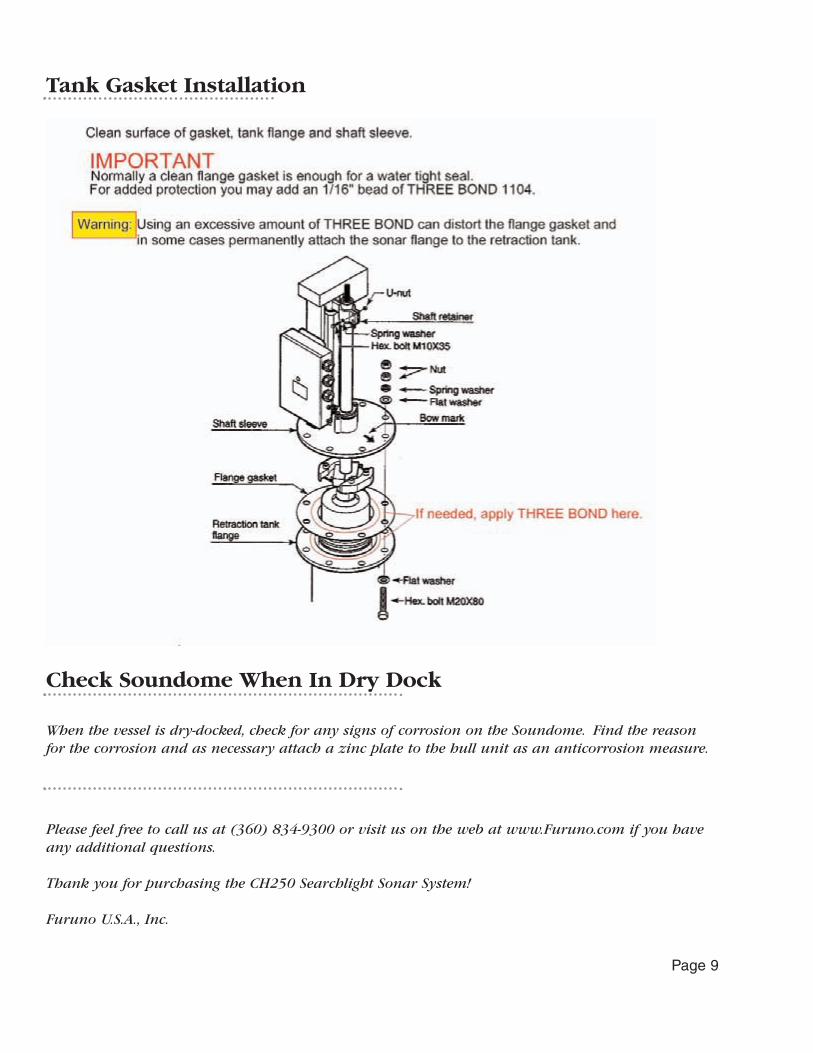
Tank Gasket Installation
Page 9
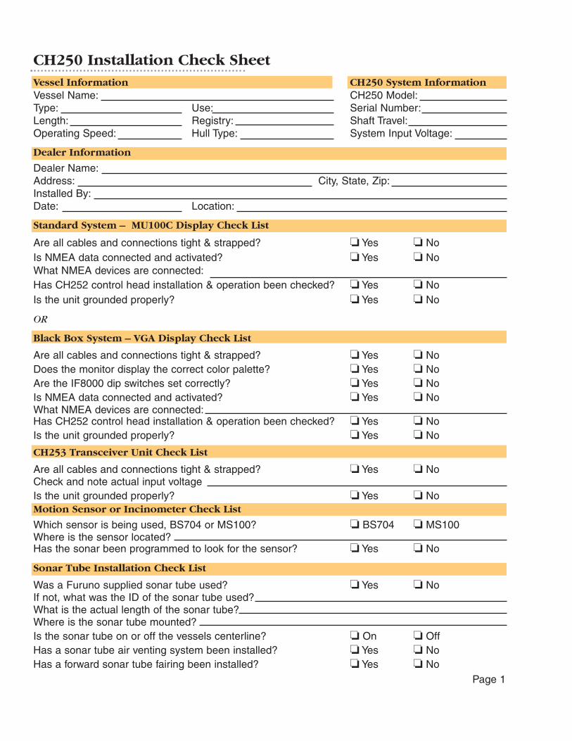
CH250 Installation Check SheetVessel Information CH250 System InformationVessel Name: CH250 Model:Type: Use: Serial Number:Length: Registry: Shaft Travel:Operating Speed: Hull Type: System Input Voltage:
Dealer Information
Dealer Name:Address: City, State, Zip:Installed By:Date: Location:
Standard System – MU100C Display Check List
Are all cables and connections tight & strapped? � Yes � NoIs NMEA data connected and activated? � Yes � NoWhat NMEA devices are connected:Has CH252 control head installation & operation been checked? � Yes � NoIs the unit grounded properly? � Yes � No
OR
Black Box System – VGA Display Check List
Are all cables and connections tight & strapped? � Yes � NoDoes the monitor display the correct color palette? � Yes � NoAre the IF8000 dip switches set correctly? � Yes � NoIs NMEA data connected and activated? � Yes � NoWhat NMEA devices are connected:Has CH252 control head installation & operation been checked? � Yes � NoIs the unit grounded properly? � Yes � No
CH253 Transceiver Unit Check List
Are all cables and connections tight & strapped? � Yes � NoCheck and note actual input voltageIs the unit grounded properly? � Yes � NoMotion Sensor or Incinometer Check List
Which sensor is being used, BS704 or MS100? � BS704 � MS100Where is the sensor located?Has the sonar been programmed to look for the sensor? � Yes � No
Sonar Tube Installation Check List
Was a Furuno supplied sonar tube used? � Yes � NoIf not, what was the ID of the sonar tube used?What is the actual length of the sonar tube?Where is the sonar tube mounted?Is the sonar tube on or off the vessels centerline? � On � OffHas a sonar tube air venting system been installed? � Yes � NoHas a forward sonar tube fairing been installed? � Yes � No
Motion Sensors, Inclinometers and Longer Interconnect Cables
This valuable accessory unit must be mounted correctly to obtain any benefit from it:a) Select a mounting location that is dry and vibration free b) The selected location should be as close to the sonar hoist unit as possiblec) Mount the unit level (only compensating for normal vessel trim) d) Line the unit up "fore and aft" accurately e) Mount the unit "right side up" only
If a longer interconnect cable assembly is required, the following options are available:
Part number DescriptionMS1-CBL-15M 15 meter signal cable assemblyMS1-CBL-30M 30 meter signal cable assemblyMS1-CBL-50M 50 meter signal cable assembly
Note:The MS100 compensates for any vessel pitching and rolling at sea. To properly set itself themotion sensor must be powered up while the vessel is in a stable condition. This step is easi-er to accomplish at the dock. Please get in the habit of powering up the entire CH250 systemprior to departing from the dock. This one easy step will ensure proper operation of theMS100 and enhanced CH250 performance for the duration of the voyage.
Soundome Cover Removal and Replacement
Remember to detach or replace the soundome cover assembly, ONLY remove the 10stainless steel Allen head cap screws! These are the cap screws that hold the soundomecover assembly to the upper bronze housing.
The plastic cover cross head screws should never be touched! This cover has been factorysealed and cannot be replaced in the field without destroying the soundome's watertightintegrity and warranty.
Once the soundome has been filled with oil, keep it in a vertical position to prevent anyinternal seepage. If the soundome assembly has to be removed for repair or shipment, the oilmust always be removed.You may wish to retain the soundome packing material for futureuse.
Page 1Page 8
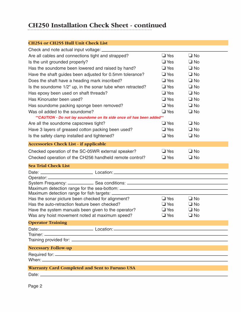
CH250 Installation Check Sheet - continued
CH254 or CH255 Hull Unit Check List
Check and note actual input voltage:Are all cables and connections tight and strapped? � Yes � NoIs the unit grounded properly? � Yes � NoHas the soundome been lowered and raised by hand? � Yes � NoHave the shaft guides been adjusted for 0.5mm tolerance? � Yes � NoDoes the shaft have a heading mark inscribed? � Yes � NoIs the soundome 1/2" up, in the sonar tube when retracted? � Yes � NoHas epoxy been used on shaft threads? � Yes � NoHas Kinoruster been used? � Yes � NoHas soundome packing sponge been removed? � Yes � NoWas oil added to the soundome? � Yes � No
**CAUTION - Do not lay soundome on its side once oil has been added**
Are all the soundome capscrews tight? � Yes � NoHave 3 layers of greased cotton packing been used? � Yes � NoIs the safety clamp installed and tightened? � Yes � No
Accessories Check List - if applicable
Checked operation of the SC-05WR external speaker? � Yes � NoChecked operation of the CH256 handheld remote control? � Yes � No
Sea Trial Check List
Date: Location:Operator:System Frequency: Sea conditions:Maximum detection range for the sea-bottom:Maximum detection range for fish targets:Has the sonar picture been checked for alignment? � Yes � NoHas the auto-retraction feature been checked? � Yes � NoHave the system manuals been given to the operator? � Yes � NoWas any hoist movement noted at maximum speed? � Yes � No
Operator Training
Date: Location:Trainer:Training provided for:
Necessary Follow-up
Required for:When:
Warranty Card Completed and Sent to Furuno USA
Date:
Page 2 Page 7

Page 3Page 6
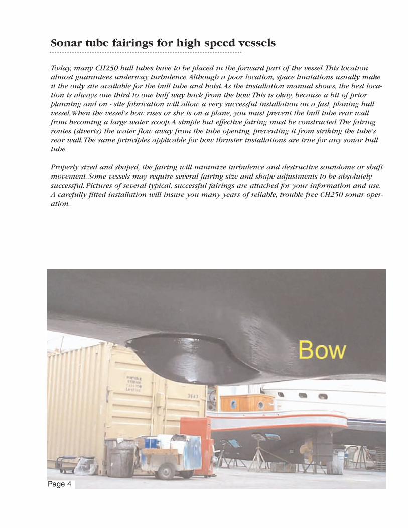
Sonar tube fairings for high speed vessels
Today, many CH250 hull tubes have to be placed in the forward part of the vessel.This locationalmost guarantees underway turbulence.Although a poor location, space limitations usually makeit the only site available for the hull tube and hoist.As the installation manual shows, the best loca-tion is always one third to one half way back from the bow.This is okay, because a bit of priorplanning and on - site fabrication will allow a very successful installation on a fast, planing hullvessel.When the vessel's bow rises or she is on a plane, you must prevent the hull tube rear wallfrom becoming a large water scoop.A simple but effective fairing must be constructed.The fairingroutes (diverts) the water flow away from the tube opening, preventing it from striking the tube'srear wall.The same principles applicable for bow thruster installations are true for any sonar hulltube.
Properly sized and shaped, the fairing will minimize turbulence and destructive soundome or shaftmovement. Some vessels may require several fairing size and shape adjustments to be absolutelysuccessful. Pictures of several typical, successful fairings are attached for your information and use.A carefully fitted installation will insure you many years of reliable, trouble free CH250 sonar oper-ation.
Page 4 Page 5
Page 3Page 6

CH250 Installation Check Sheet - continued
CH254 or CH255 Hull Unit Check List
Check and note actual input voltage:Are all cables and connections tight and strapped? � Yes � NoIs the unit grounded properly? � Yes � NoHas the soundome been lowered and raised by hand? � Yes � NoHave the shaft guides been adjusted for 0.5mm tolerance? � Yes � NoDoes the shaft have a heading mark inscribed? � Yes � NoIs the soundome 1/2" up, in the sonar tube when retracted? � Yes � NoHas epoxy been used on shaft threads? � Yes � NoHas Kinoruster been used? � Yes � NoHas soundome packing sponge been removed? � Yes � NoWas oil added to the soundome? � Yes � No
**CAUTION - Do not lay soundome on its side once oil has been added**
Are all the soundome capscrews tight? � Yes � NoHave 3 layers of greased cotton packing been used? � Yes � NoIs the safety clamp installed and tightened? � Yes � No
Accessories Check List - if applicable
Checked operation of the SC-05WR external speaker? � Yes � NoChecked operation of the CH256 handheld remote control? � Yes � No
Sea Trial Check List
Date: Location:Operator:System Frequency: Sea conditions:Maximum detection range for the sea-bottom:Maximum detection range for fish targets:Has the sonar picture been checked for alignment? � Yes � NoHas the auto-retraction feature been checked? � Yes � NoHave the system manuals been given to the operator? � Yes � NoWas any hoist movement noted at maximum speed? � Yes � No
Operator Training
Date: Location:Trainer:Training provided for:
Necessary Follow-up
Required for:When:
Warranty Card Completed and Sent to Furuno USA
Date:
Page 2 Page 7
CH250 Installation Check SheetVessel Information CH250 System InformationVessel Name: CH250 Model:Type: Use: Serial Number:Length: Registry: Shaft Travel:Operating Speed: Hull Type: System Input Voltage:
Dealer Information
Dealer Name:Address: City, State, Zip:Installed By:Date: Location:
Standard System – MU100C Display Check List
Are all cables and connections tight & strapped? � Yes � NoIs NMEA data connected and activated? � Yes � NoWhat NMEA devices are connected:Has CH252 control head installation & operation been checked? � Yes � NoIs the unit grounded properly? � Yes � No
OR
Black Box System – VGA Display Check List
Are all cables and connections tight & strapped? � Yes � NoDoes the monitor display the correct color palette? � Yes � NoAre the IF8000 dip switches set correctly? � Yes � NoIs NMEA data connected and activated? � Yes � NoWhat NMEA devices are connected:Has CH252 control head installation & operation been checked? � Yes � NoIs the unit grounded properly? � Yes � No
CH253 Transceiver Unit Check List
Are all cables and connections tight & strapped? � Yes � NoCheck and note actual input voltageIs the unit grounded properly? � Yes � NoMotion Sensor or Incinometer Check List
Which sensor is being used, BS704 or MS100? � BS704 � MS100Where is the sensor located?Has the sonar been programmed to look for the sensor? � Yes � No
Sonar Tube Installation Check List
Was a Furuno supplied sonar tube used? � Yes � NoIf not, what was the ID of the sonar tube used?What is the actual length of the sonar tube?Where is the sonar tube mounted?Is the sonar tube on or off the vessels centerline? � On � OffHas a sonar tube air venting system been installed? � Yes � NoHas a forward sonar tube fairing been installed? � Yes � No
Motion Sensors, Inclinometers and Longer Interconnect Cables
This valuable accessory unit must be mounted correctly to obtain any benefit from it:a) Select a mounting location that is dry and vibration free b) The selected location should be as close to the sonar hoist unit as possiblec) Mount the unit level (only compensating for normal vessel trim) d) Line the unit up "fore and aft" accurately e) Mount the unit "right side up" only
If a longer interconnect cable assembly is required, the following options are available:
Part number DescriptionMS1-CBL-15M 15 meter signal cable assemblyMS1-CBL-30M 30 meter signal cable assemblyMS1-CBL-50M 50 meter signal cable assembly
Note:The MS100 compensates for any vessel pitching and rolling at sea. To properly set itself themotion sensor must be powered up while the vessel is in a stable condition. This step is easi-er to accomplish at the dock. Please get in the habit of powering up the entire CH250 systemprior to departing from the dock. This one easy step will ensure proper operation of theMS100 and enhanced CH250 performance for the duration of the voyage.
Soundome Cover Removal and Replacement
Remember to detach or replace the soundome cover assembly, ONLY remove the 10stainless steel Allen head cap screws! These are the cap screws that hold the soundomecover assembly to the upper bronze housing.
The plastic cover cross head screws should never be touched! This cover has been factorysealed and cannot be replaced in the field without destroying the soundome's watertightintegrity and warranty.
Once the soundome has been filled with oil, keep it in a vertical position to prevent anyinternal seepage. If the soundome assembly has to be removed for repair or shipment, the oilmust always be removed.You may wish to retain the soundome packing material for futureuse.
Page 1Page 8
CH250 Installation Supplement Contents
The following checklist and information sheets are provided to help you properly and efficientlyinstall your CH250 sonar. If this is a high speed vessel, please pay careful attention to the tube lengthand fairing instructions.
Page
1-2 Overall installation checklist - Please return a completed copy to Furuno U.S.A.
3 Fiberglass (FRP) sonar tube installation outline drawing
4-6 High speed hull, sonar tube fairing pictures with comment
7 Tank guide assembly installation and adjustment instructions
8 Motion sensor mounting, location and longer interconnect cables
8 Soundome cover and oil installation reminder
9 Tank gasket installation
9 Check soundome when in drydock
Please feel free to contact us with any questions that you may have.Additional information such asthis may be found on our web site www.Furuno.com.
This material is provided to augment, not replace, what is found in your CH250 manuals.
Check Soundome When In Dry Dock
When the vessel is dry-docked, check for any signs of corrosion on the Soundome. Find the reasonfor the corrosion and as necessary attach a zinc plate to the hull unit as an anticorrosion measure.
Please feel free to call us at (360) 834-9300 or visit us on the web at www.Furuno.com if you haveany additional questions.
Thank you for purchasing the CH250 Searchlight Sonar System!
Furuno U.S.A., Inc.
Tank Gasket Installation
Page 9