improved tube-to-tube connector: low cost + superior sealing performance
TRANSCRIPT
Improved Tube-To-Tube Connector:
Low Cost + Superior Sealing
Performance
A cost saving proposal through incorporation
of a recently invented sphere based flare
(U.S. Patent 8 152 204)
Presented by S. Pliassounov, PhD, P. Eng April 2012
Executive Summary The recently invented sphere based innovative flare (US Patent 8152204)
advances the sealing performance of a tube-to-tube connector far beyond the
level of a conventional union connector yet without the cost disadvantages of the
latter
Superior sealing robustness comes together with the cost-per-unit saving
estimated at $0.50 …$1.50 comparing to a union connector
That new sphere based flare has been designed to fit into standard ISO bubble
flare port (as per SAE J1290/ISO 4038 or compatible)
The new flare delivers guaranteed unvarying width of the contact/mating ring (the
sealing length) which is resilient to disturbances/misalignment and more forgiving
to surface deviations/imperfections – no more leaks!
Such misalignment resilience also opens the opportunity to develop and market a
cost effective proprietary quick connector with superb sealing robustness
The Patent Owner is seeking a partnership to implement/market this solution
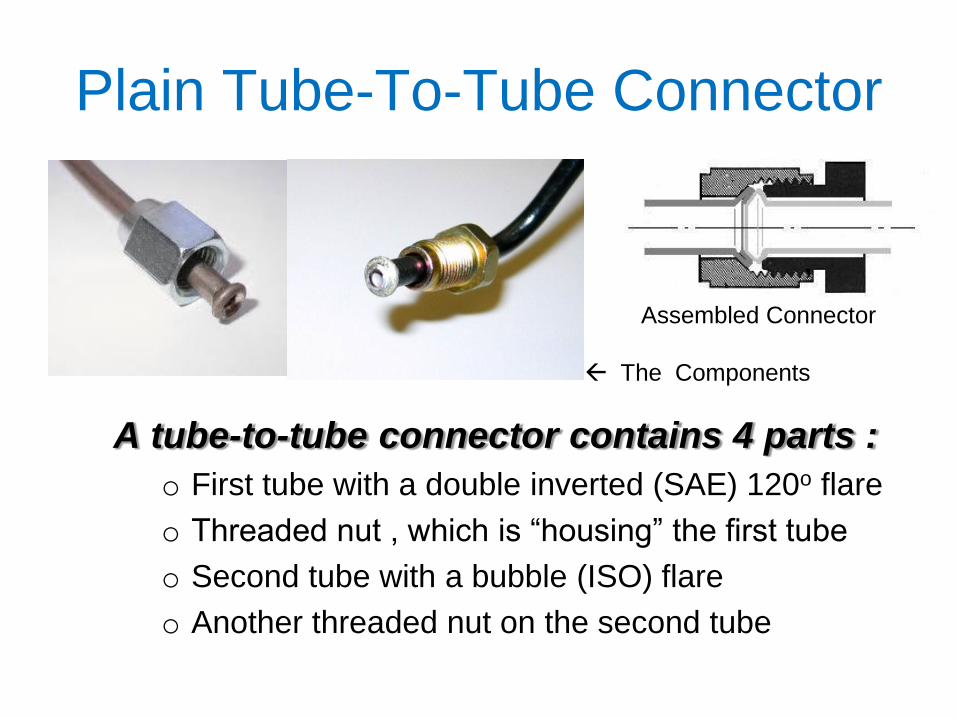
Plain Tube-To-Tube Connector
A tube-to-tube connector contains 4 parts :
o First tube with a double inverted (SAE) 120o flare
o Threaded nut , which is “housing” the first tube
o Second tube with a bubble (ISO) flare
o Another threaded nut on the second tube
Assembled Connector
The Components
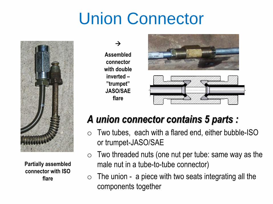
Union Connector
A union connector contains 5 parts :
o Two tubes, each with a flared end, either bubble-ISO
or trumpet-JASO/SAE
o Two threaded nuts (one nut per tube: same way as the
male nut in a tube-to-tube connector)
o The union - a piece with two seats integrating all the
components together
Partially assembled
connector with ISO
flare
Assembled
connector
with double
inverted –
”trumpet”
JASO/SAE
flare
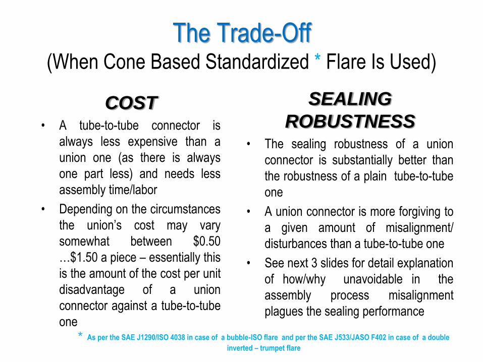
The Trade-Off (When Cone Based Standardized * Flare Is Used)
COST • A tube-to-tube connector is
always less expensive than a
union one (as there is always
one part less) and needs less
assembly time/labor
• Depending on the circumstances
the union’s cost may vary
somewhat between $0.50
…$1.50 a piece – essentially this
is the amount of the cost per unit
disadvantage of a union
connector against a tube-to-tube
one
SEALING
ROBUSTNESS • The sealing robustness of a union
connector is substantially better than
the robustness of a plain tube-to-tube
one
• A union connector is more forgiving to
a given amount of misalignment/
disturbances than a tube-to-tube one
• See next 3 slides for detail explanation
of how/why unavoidable in the
assembly process misalignment
plagues the sealing performance
* As per the SAE J1290/ISO 4038 in case of a bubble-ISO flare and per the SAE J533/JASO F402 in case of a double
inverted – trumpet flare
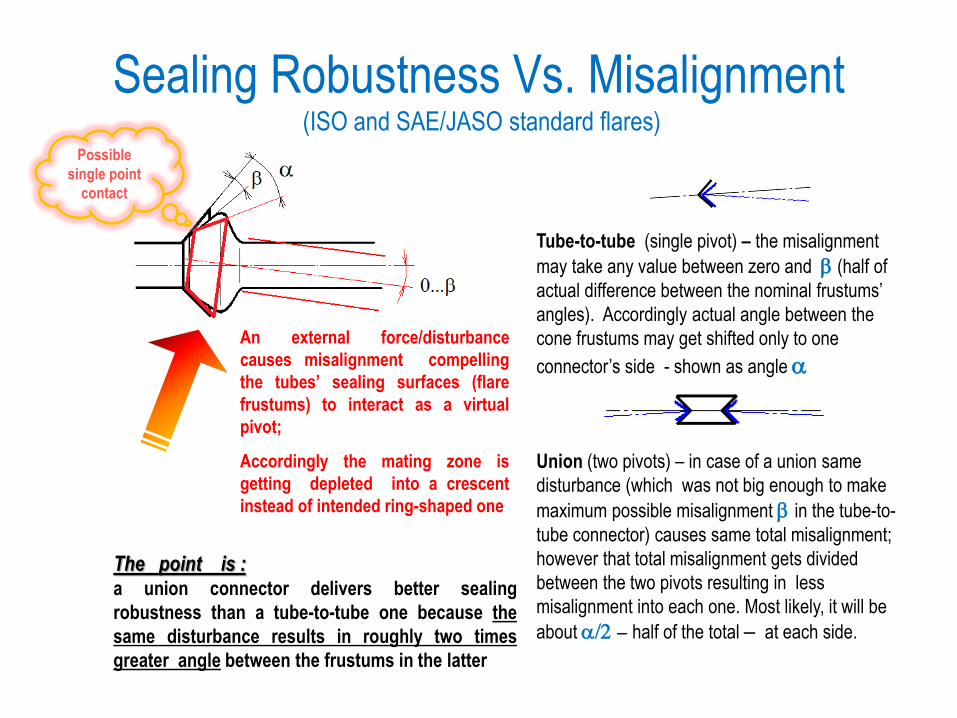
Sealing Robustness Vs. Misalignment (ISO and SAE/JASO standard flares)
An external force/disturbance
causes misalignment compelling
the tubes’ sealing surfaces (flare
frustums) to interact as a virtual
pivot;
Accordingly the mating zone is
getting depleted into a crescent
instead of intended ring-shaped one
Tube-to-tube (single pivot) – the misalignment
may take any value between zero and b (half of
actual difference between the nominal frustums’
angles). Accordingly actual angle between the
cone frustums may get shifted only to one
connector’s side - shown as angle a
Union (two pivots) – in case of a union same
disturbance (which was not big enough to make
maximum possible misalignment b in the tube-to-
tube connector) causes same total misalignment;
however that total misalignment gets divided
between the two pivots resulting in less
misalignment into each one. Most likely, it will be
about a/2 - half of the total - at each side.
The point is : a union connector delivers better sealing
robustness than a tube-to-tube one because the
same disturbance results in roughly two times
greater angle between the frustums in the latter
Possible
single point
contact
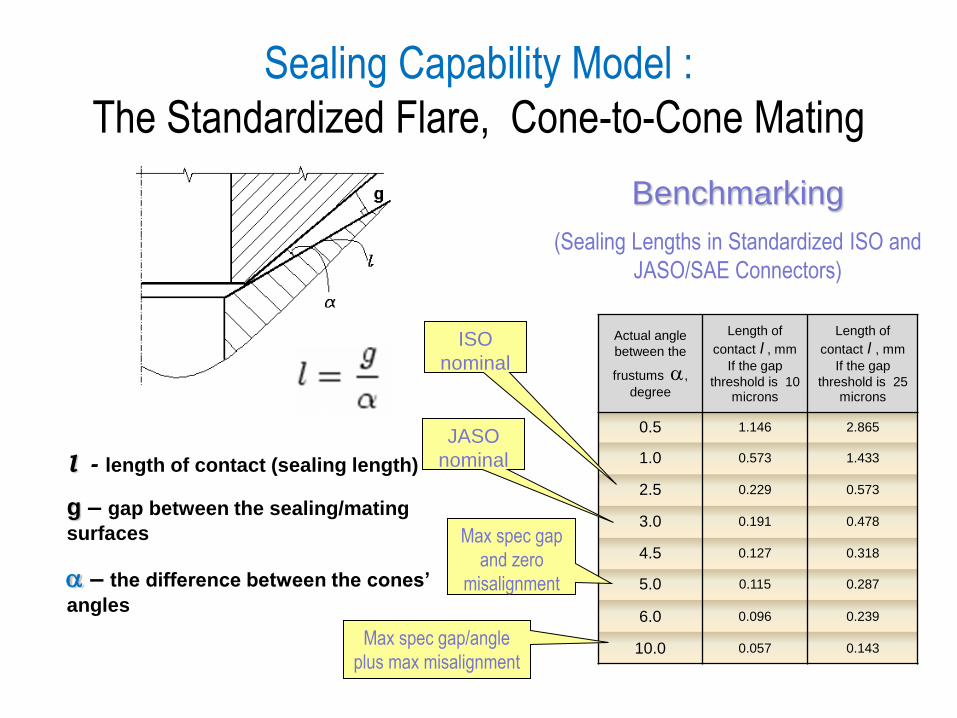
Sealing Capability Model :
The Standardized Flare, Cone-to-Cone Mating
Benchmarking
(Sealing Lengths in Standardized ISO and
JASO/SAE Connectors)
l - length of contact (sealing length)
g – gap between the sealing/mating
surfaces
a – the difference between the cones’
angles
Actual angle
between the
frustums a,
degree
Length of
contact l , mm
If the gap
threshold is 10 microns
Length of
contact l , mm
If the gap
threshold is 25 microns
0.5 1.146 2.865
1.0 0.573 1.433
2.5 0.229 0.573
3.0 0.191 0.478
4.5 0.127 0.318
5.0 0.115 0.287
6.0 0.096 0.239
10.0 0.057 0.143
JASO
nominal
ISO
nominal
Max spec gap
and zero
misalignment
Max spec gap/angle
plus max misalignment
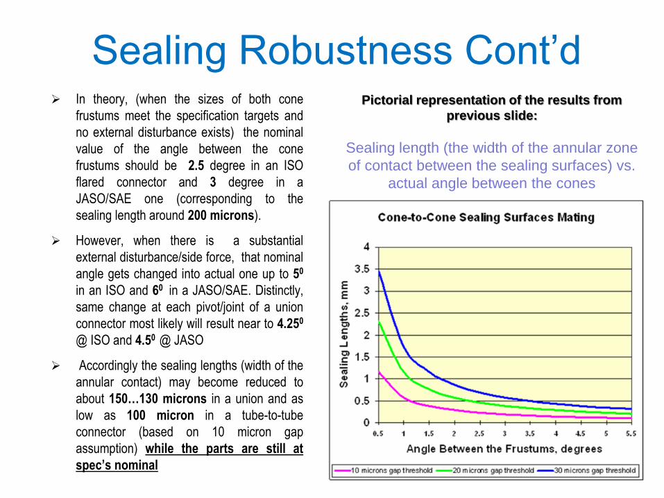
Sealing Robustness Cont’d In theory, (when the sizes of both cone
frustums meet the specification targets and
no external disturbance exists) the nominal
value of the angle between the cone
frustums should be 2.5 degree in an ISO
flared connector and 3 degree in a
JASO/SAE one (corresponding to the
sealing length around 200 microns).
However, when there is a substantial
external disturbance/side force, that nominal
angle gets changed into actual one up to 50
in an ISO and 60 in a JASO/SAE. Distinctly,
same change at each pivot/joint of a union
connector most likely will result near to 4.250
@ ISO and 4.50 @ JASO
Accordingly the sealing lengths (width of the
annular contact) may become reduced to
about 150…130 microns in a union and as
low as 100 micron in a tube-to-tube
connector (based on 10 micron gap
assumption) while the parts are still at
spec’s nominal
Pictorial representation of the results from
previous slide:
Sealing length (the width of the annular zone
of contact between the sealing surfaces) vs.
actual angle between the cones
How to Break Up the Trade-Off? (how to get rid of unwanted misalignment influence inherent to
a cone based flare)
The Solution is - new innovative sphere based flare design which
delivers no dependency between angular misalignment and the
contact/mating ring’s width (the sealing lengths)
That new flare always delivers ring-shaped sealing/contact area and
on top of that its sealing lengths is much greater than one in existing
cone based connectors
A single point contact is simply unrealizable with such sphere based
flare; accordingly the sealing sensitivity to unavoidable dimensional
variation and imperfections has been substantially reduced
Correspondingly, it becomes possible to combine the cost
advantages of a plane tube-to-tube design with the sealing
robustness far better than the union’s one

The Solution - a Standard* Concave Cone
Seat with New Sphere Based Flare
As per the U.S. Patent 8 152 204 and
Canadian Patent 2 593 305
* As per the SAE J1290/ISO 4038
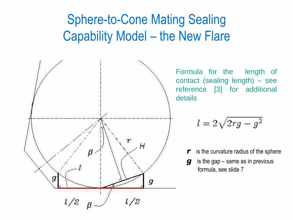
Sphere-to-Cone Mating Sealing
Capability Model – the New Flare
Formula for the length of
contact (sealing length) – see
reference [3] for additional
details
r is the curvature radius of the sphere
g is the gap – same as in previous
formula, see slide 7
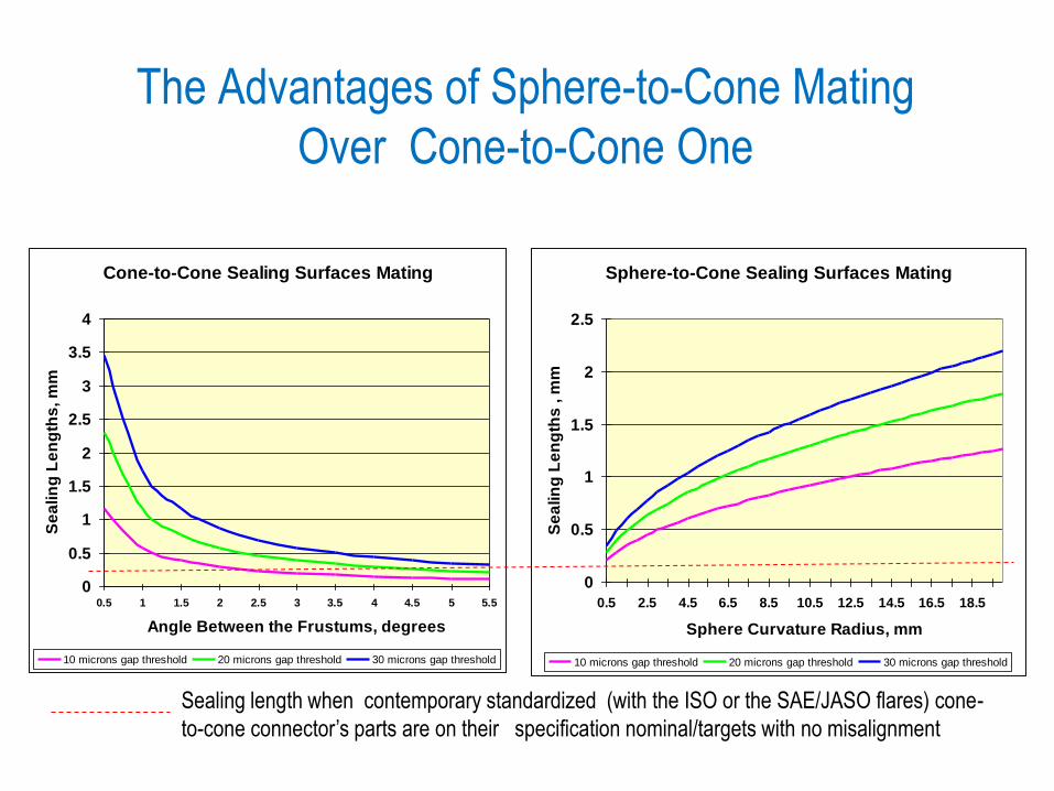
The Advantages of Sphere-to-Cone Mating
Over Cone-to-Cone One
Cone-to-Cone Sealing Surfaces Mating
0
0.5
1
1.5
2
2.5
3
3.5
4
0.5 1 1.5 2 2.5 3 3.5 4 4.5 5 5.5
Angle Between the Frustums, degrees
Se
alin
g L
en
gth
s, m
m
10 microns gap threshold 20 microns gap threshold 30 microns gap threshold
Sphere-to-Cone Sealing Surfaces Mating
0
0.5
1
1.5
2
2.5
0.5 2.5 4.5 6.5 8.5 10.5 12.5 14.5 16.5 18.5
Sphere Curvature Radius, mm
Se
alin
g L
en
gth
s , m
m
10 microns gap threshold 20 microns gap threshold 30 microns gap threshold
Sealing length when contemporary standardized (with the ISO or the SAE/JASO flares) cone-
to-cone connector’s parts are on their specification nominal/targets with no misalignment
New Sphere Based Flare :
Summary of the Advantages • The contact zone is always ring-shaped due to a fundamental property of
the cone to sphere intersection; the crescent shape is impossible
• The width of the contact/mating ring-shaped zone (the sealing length) is not
affected by connector components’ misalignment and external disturbances
• The size of the sealing length is far greater (minimum 300 micron and the
nominal can easily be greater than 1 mm) comparing to current
standardized connectors (with the nominal being around 200 micron)
• Longer sealing length enables less sensitivity to surface imperfections and
local defects like notches, micro-bumps, local bruises/voids, dimples etc.
• The contact/mating occurs between the surfaces with substantially less
geometry variation and local imperfections comparing to current
standardized connectors with cone based flares
• Initial contact by flare’s inner edge (the former raw tube’s butt/cut-off) is
impossible – the influence from the geometry variation inherent to the end-
forming manufacturing process has been reduced substantially
• Initial single-point contact between flare and seat is impossible therefore
new flare is also resilient to the locked misalignment phenomenon
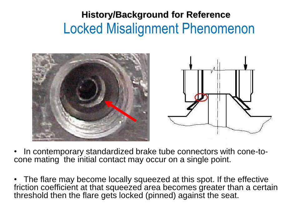
History/Background for Reference
Locked Misalignment Phenomenon
• In contemporary standardized brake tube connectors with cone-to-cone mating the initial contact may occur on a single point.
• The flare may become locally squeezed at this spot. If the effective friction coefficient at that squeezed area becomes greater than a certain threshold then the flare gets locked (pinned) against the seat.
Quick Connector Opportunity • Simple replacement of the threaded joint with an unfussy device to execute
quick clamping is not suitable for current standardized cone-based sealing
because of the following reason. While the threads being torqued (securing
operation) the connector’s components are moving against each other having
the opportunity to correct some misalignment. The threaded joint actually fulfills
two functions: to generate the clamping force between the sealing surfaces and
to align connector’s components prior that clamping. Therefore the device to
execute quick clamping is also supposed to provide the alignment.
Correspondingly, such “two functions burden” makes the device design quite
complicated because these functions contradict to each other. Snap latching
does not allow enough time to accomplish alignment, likewise relatively slow
alignment process forbids momentary clamping.
• The new sphere based flare (U.S. Patent 8152204) does not require such
alignment. Therefore the device to execute quick clamping in this case may be
radically simplified as it has to perform only one function – fast latching.
• Accordingly, the new sphere based flare (U.S. Patent 8152204) opens the
window of opportunity to develop a robust cost effective proprietary quick
connector based on a simple clamping structure. Needless to say that such
product would be a hit on the market delivering prospects to grow the business
coupled with huge advantages over the competitors.
New sphere shaped flare design
1. Pliassounov, S. Flared brake tube connector, Canadian Patent 2 593 305
2. Pliassounov, S., Flared brake tube connector, US Patent 8 152 204
Spare-to-Cone mating advantages
3. Pliassounov, S., "Sphere-To-Cone Mating – New Solution to Improve Brake Tube Connector Sealing
Robustness," SAE Int. J. Mater. Manuf. 2(2):8-18, 2010, doi:10.4271/2009-01-3024.
http://saematman.saejournals.org/content/2/2/8.short
http://www.sae.org/events/bce/presentations/2009/pliassounov.pdf
Locked misalignment phenomenon , crescent-shaped contact/mating zone and other inherent shortcomings of
standardized ISO/JASO/SAE connectors
4. Pliassounov, S., "Fundamentals and Common Problems of Seal Integrity Robustness of Standardized
Brake Tubing Threaded Connectors," SAE Technical Paper 2007-01-0557, 2007, doi:10.4271/2007-01-
0557
http://papers.sae.org/2007-01-0557
References