improving configuration management processes of a software … · 2015-07-29 · tik-76 supervisor:...
TRANSCRIPT
HELSINKI UNIVERSITY OF TECHNOLOGY
Department of Computer Science
Laboratory of Information Processing Science
Jari Vanhanen
Improving configuration management processesof a software product
Master’s Thesis
Supervisor: Professor Reijo Sulonen
Instructor: M.Sc. Kari Alho

ii
iii
HELSINKI UNIVERSITY OF ABSTRACT OF THE
TECHNOLOGY MASTER’S THESIS
Author and name of the thesis:Jari VanhanenImproving configuration management processes of a software productDate: 11.12.1997 Number of pages: 62Department:Department of Computer Science, Laboratoryof Information Processing Science
Professorship:Tik-76
Supervisor:Professor Reijo SulonenInstructor:M.Sc. Kari Alho, Helsinki University of Technology
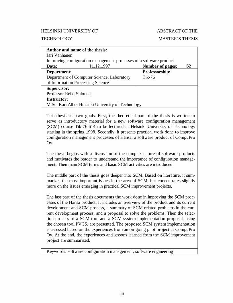
This thesis has two goals. First, the theoretical part of the thesis is written toserve as introductory material for a new software configuration management(SCM) course Tik-76.614 to be lectured at Helsinki University of Technologystarting in the spring 1998. Secondly, it presents practical work done to improveconfiguration management processes of Hansa, a software product of CompuProOy.
The thesis begins with a discussion of the complex nature of software productsand motivates the reader to understand the importance of configuration manage-ment. Then main SCM terms and basic SCM activities are introduced.
The middle part of the thesis goes deeper into SCM. Based on literature, it sum-marizes the most important issues in the area of SCM, but concentrates slightlymore on the issues emerging in practical SCM improvement projects.
The last part of the thesis documents the work done in improving the SCM proc-esses of the Hansa product. It includes an overview of the product and its currentdevelopment and SCM process, a summary of SCM related problems in the cur-rent development process, and a proposal to solve the problems. Then the selec-tion process of a SCM tool and a SCM system implementation proposal, usingthe chosen tool PVCS, are presented. The proposed SCM system implementationis assessed based on the experiences from an on-going pilot project at CompuProOy. At the end, the experiences and lessons learned from the SCM improvementproject are summarized.
Keywords: software configuration management, software engineering
iv
TEKNILLINEN KORKEAKOULU DIPLOMITYÖN
TIIVISTELMÄ
Tekijä ja työn nimi:Jari VanhanenErään ohjelmistotuotteen konfiguraationhallintaprosessien parantaminenPäivämäärä: 11.12.1997 Sivumäärä: 62Osasto:Tietotekniikan osasto, tietojenkäsittelyopinlaboratorio
Professuuri:Tik-76
Työn valvoja:Professori Reijo SulonenTyön ohjaaja:DI Kari Alho, Teknillinen korkeakoulu
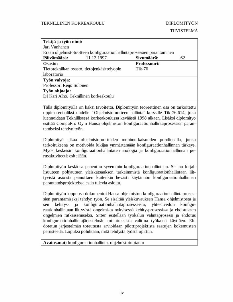
Tällä diplomityöllä on kaksi tavoitetta. Diplomityön teoreettinen osa on tarkoitettuoppimateriaaliksi uudelle “Ohjelmistotuotteen hallinta”-kurssille Tik-76.614, jokaluennoidaan Teknillisessä korkeakoulussa keväästä 1998 alkaen. Lisäksi diplomityöesittää CompuPro Oy:n Hansa ohjelmiston konfiguraationhallintaprosessien paran-tamiseksi tehdyn työn.
Diplomityö alkaa ohjelmistotuotteiden monimutkaisuuden pohdinnalla, jonkatarkoituksena on motivoida lukijaa ymmärtämään konfiguraationhallinnan tärkeys.Myös keskeisin konfiguraationhallintaterminologia ja konfiguraationhallinnan pe-rusaktiviteetit esitellään.
Diplomityön keskiosa paneutuu syvemmin konfiguraationhallintaan. Se luo kirjal-lisuuteen pohjautuen yleiskatsauksen tärkeimmistä konfiguraationhallintaan liit-tyvistä asioista painottaen kuitenkin lievästi käytännön konfiguraationhallinnanparantamisprojekteissa esiin tulevia asioita.
Diplomityön loppuosa dokumentoi Hansa ohjelmiston konfiguraationhallintaproses-sien parantamiseksi tehdyn työn. Se sisältää yleiskuvauksen Hansa ohjelmistosta jasen kehitys- ja konfiguraationhallintaprosesseista, yhteenvedon konfigu-raationhallintaan liittyvistä ongelmista nykyisessä kehitysprosessissa ja ehdotuksenongelmien ratkaisemiseksi. Sitten esitellään työkalun valintaprosessi ja ehdotuskonfiguraationhallintajärjestelmän toteutuksesta valittua työkalua käyttäen. Eh-dotetun järjestelmän toteutusta arvioidaan pilottiprojektista saatujen kokemustenperusteella. Lopuksi pohditaan, mitä tehdystä työstä opittiin.
Avainsanat: konfiguraationhallinta, ohjelmistotuotanto
v
PREFACE
This thesis has been written at Helsinki University of Technology at the Laboratory of
Information Processing Science during the autumn 1997. The practical work, docu-
mented in the thesis, started in the spring 1997 as a part of SOIHTU project. The work
was done for a company called CompuPro Oy located in Turku. The implementation of
the proposals presented in this thesis continues at the premises of CompuPro Oy in con-
nection with a new project, LUCOS.
I would like to thank my supervisor Professor Reijo Sulonen and my instructor Kari Alho
for their comments on the work I have done. Kari Alho has been extremely helpful in re-
viewing thoroughly both the contents and the layout of the drafts of the thesis.
The people at CompuPro Oy have used a lot of time in meetings, where we have to-
gether discussed their configuration management improvement issues. I would like to
thank all, who have participated in the project at CompuPro Oy, especially Jari Palsio,
who has been leading the pilot project implementing my proposal at CompuPro Oy.
Special thanks also to my work mates Casper and Kristian for constantly encouraging me
to finish this thesis.
Espoo, 11.12.1997
Jari Vanhanen
vi
TABLE OF CONTENTS
1 Introduction........................................................................................................ i
1.1 Background .................................................................................................1
1.2 Objectives ....................................................................................................1
1.3 Structure of the Thesis .................................................................................2
2 What is Software Configuration Management?...................................................3
2.1 Complexity of a Software Product ...............................................................3
2.2 Introduction to Software Configuration Management...................................6
2.2.1History of Software Configuration Management ..................................6
2.2.2Definition of Software Configuration Management .............................6
2.2.3SCM Activities ....................................................................................8
Identification .......................................................................................8
Control ................................................................................................8
Status Accounting ...............................................................................9
Auditing ..............................................................................................9
Interface Control .................................................................................9
Subcontractor/Vendor Control........................................................... 10
Manufacture ...................................................................................... 10
Process Management ......................................................................... 10
Team Work ....................................................................................... 10
3 SCM Models ................................................................................................... 11
3.1 The Checkout/Checkin Model.................................................................... 11
3.2 The Composition Model ............................................................................ 12
3.3 The Long Transaction Model ..................................................................... 14
3.4 The Change Set Model............................................................................... 16
4 SCM Functionality Areas................................................................................. 18
4.1 Components............................................................................................... 19
4.1.1Versioning Dimensions ...................................................................... 19
4.1.2Versioning Models............................................................................. 19
4.1.3 Identification Schemes ....................................................................... 19
vii
4.1.4Version Differences ........................................................................... 20
4.1.5Repositories....................................................................................... 20
4.1.6Managing Variance............................................................................ 21
4.2 Structure.................................................................................................... 21
4.2.1System Models .................................................................................. 21
4.2.2Configurations ................................................................................... 21
4.3 Construction .............................................................................................. 23
4.3.1 Incremental Construction................................................................... 23
4.3.2Determining Dependencies Automatically .......................................... 25
4.3.3 Identification of Derived Items........................................................... 26
4.4 Team ......................................................................................................... 26
4.4.1Private Directories ............................................................................. 26
4.4.2 Integrating Workspaces and Repositories........................................... 27
4.4.3Cooperation Strategies ...................................................................... 28
4.4.4Merging and Conflict Resolution........................................................ 28
4.4.5Multi-site Development ..................................................................... 29
4.5 Process Centered Functionality Areas......................................................... 30
4.5.1Accounting ........................................................................................ 30
4.5.2Auditing ............................................................................................ 30
4.5.3Controlling ........................................................................................ 31
4.5.4Process .............................................................................................. 33
5 Adopting SCM ................................................................................................ 34
5.1 Initiating a SCM Improvement Project ....................................................... 35
5.2 Selection of a Tool..................................................................................... 36
5.2.1Categories of Tools ........................................................................... 36
5.2.2Selection Process............................................................................... 37
5.3 Implementation .......................................................................................... 38
6 Implementing SCM Processes of the Hansa software ....................................... 40
6.1 Overview of the Hansa Software Development Process.............................. 40
6.1.1 Introduction....................................................................................... 40
6.1.2Structure ........................................................................................... 40
6.1.3Versioning ......................................................................................... 41
viii
6.1.4Development process......................................................................... 43
6.2 Problems in the Current Development Process ........................................... 43
6.3 Proposed SCM Tasks ................................................................................ 44
6.3.1Source Code Control ......................................................................... 44
Versioning ......................................................................................... 44
Customizations .................................................................................. 45
Changes............................................................................................. 46
Special files........................................................................................ 48
6.3.2Problem Reports and Change Requests .............................................. 48
6.3.3Documentation .................................................................................. 48
6.3.4Other Tasks ....................................................................................... 49
6.4 Selection of a Tool..................................................................................... 49
6.4.1Selection Criteria ............................................................................... 49
6.4.2Evaluating Tools................................................................................ 51
Survey of Available Tools.................................................................. 51
In-depth Survey ................................................................................. 51
Selecting the Tool.............................................................................. 52
6.5 Using PVCS to Manage Hansa Software.................................................... 54
6.5.1Overview of PVCS ............................................................................ 55
6.5.2 Implementation.................................................................................. 56
6.6 Assessing the Proposed SCM System......................................................... 57
6.7 Conclusions of the SCM Improvement Project ........................................... 58
7 References....................................................................................................... 60
1
1 INTRODUCTION
1.1 Background
The author of this work is a member of Software Engineering Group (SEG) at Helsinki
University of Technology. The mission of SEG is to improve engineering practices in
software companies through research and education. Starting from the spring 1998 SEG
will arrange a course Tik-76.614 Software Configuration Management at Helsinki Uni-
versity of Technology. There was a need for course material that would serve as an in-
troduction to the subject. In addition to getting familiar with the literature and research in
the area of configuration management, the author was involved in the SOIHTU project.
He was responsible for improving the configuration management processes of Hansa
software product of a SOIHTU project member company called CompuPro Oy.
1.2 Objectives
This thesis has two quite separate objectives. First, the theoretical part of the thesis is
written to serve as an introductory course material for the Tik-76.614 course. Based on
the literature, it summarizes the most important issues in the area of software configura-
tion management (SCM), but concentrates slightly more on the issues emerging in SCM
improvement projects.
Secondly, the thesis documents the practical work done to improve configuration man-
agement processes of Hansa product including:
• Designing better configuration management processes,
• selecting an adequate configuration management tool, and
• planning and prototyping the implementation of the main configuration management
operations using the chosen tool in the development environment.
In addition, as a general objective one can mention the strengthening of SEG’s knowl-
edge of SCM and state of SCM in the Finnish software industry.
2
1.3 Structure of the Thesis
Chapter 2 is a general introduction to software configuration management. It discusses
the complexity of a software product in order to make the importance of SCM apparent.
The motivation is followed by a definition of SCM and relevant terminology.
Chapter 3 presents a classification of commercial SCM tools into four classes based on
certain patterns observed in support of the repository, i.e., the place where all versions of
managed objects and related metadata are stored. The classes are: the checkout/checkin
model, the composition model, the long transaction model, and the change set model.
Chapter 4 presents a set of functionality areas that different users expect from a SCM
system. The functionalities are divided to team centered functionalities dealing with tech-
nical aspects of SCM and process centered areas covering management issues.
Chapter 5 deals with the issues which organizations face when improving their SCM
processes and deploying a new SCM tool. A method for carrying out an SCM improve-
ment project is presented. The presented method is a holistic one, covering all areas of
SCM. It is shortly contrasted with incremental methods where the SCM processes are
improved step by step starting from the most fundamental ones.
Chapter 6 documents the experimental part of this work. It summarizes how the SCM
improvement project in CompuPro progressed, starting from an introduction of the
product to be managed and its current configuration management processes. SCM prob-
lems in the current processes are discussed and a proposal of solving them is presented.
The selection of a SCM tool and implementation of the proposed SCM operations using
the chosen tool are described. Finally, some experiences already available of the pro-
posed system and the SCM improvement project are discussed.
3
2 WHAT IS SOFTWARE CONFIGURATION MANAGEMENT?
2.1 Complexity of a Software Product
Most modern technological products – not only computers but also devices like cellular
phones and televisions – include one or several microprocessors. Therefore, software,
which is used to control the microprocessors, surrounds us everywhere. The develop-
ment in the area of hardware technology has both led to the need and given the possibili-
ties to create increasingly more complex software systems. These systems may be huge,
reaching the size of millions of code lines and they may operate in critical environments,
e.g., in hospitals setting high demands on their reliability. Nowadays, software systems
operate more and more in distributed environments and interoperability between different
software systems is often required. The nature of software products is discussed closer
by Sommerville in [Som95] and Brooks in [Bro95].
Software can not be touched. It does not have a physical form except the media it is de-
livered on. Software can be made visible by producing abstract models of its structure,
functionality, and relationship to the real world. These models make up the documenta-
tion of a software product including, e.g., requirements specification, design specifica-
tion, and user manual. The documentation forms the basis for the development, evolution
and maintenance of the actual product. In fact, the importance of the documentation is so
essential that it is often considered a part of the software product.
Most practical software systems are divided to smaller parts. The division can be recur-
sively repeated resulting to a hierarchy. Whitfield [Whi91] uses the following terminol-
ogy for the levels of this hierarchy. The lowest level unbreakable items are components,
subsets of components are subsystems and the set of all components forms the software
system. Whitfield presents several reasons to decompose a system:
• Complexity decreases when smaller and simpler components are managed.
• Dividing the labor is easier when a person can be assigned an own subsystem to work
with.
4
• The system is easier to maintain when changes can be restricted to one part of the
system.
• Well-defined components may be used by several different parts of the system.
Almost all software products need to be changed after their initial release to the cus-
tomer. Therefore, new versions of the product emerge as long as the product is main-
tained. The reasons for the changes are many [Art88]. Bugs that have not been detected
during the testing have to be fixed. Requirements for the product may change if, e.g., the
software has to be adapted to work in a new environment. Changes may be required to
simplify the structure of the product in order to make changing the system easier in the
future. This is often profitable especially if the system is to be maintained for several
years, which by no means is unusual. There still exist systems developed in the sixties and
seventies, which are still in wide use around the world.
Increasing packaged software markets have placed new requirements on software devel-
opment [Car95]. During the development of the first version of the product, a lot of it-
eration, in the form of building prototypes and pre-releases, is required to survey the real
requirements of potential users. After the initial release of the product, new frequent ver-
sions including new features are required to keep the market share. Software mainte-
nance has changed more and more to continuos development of products, where speed
of development is a crucial factor for success in the competition.
Many software products are targeted for several different platforms. They may be of-
fered for Windows, Macintosh, UNIX systems and other environments. Furthermore,
software may be customized to individual customers by making changes here and there.
Therefore, some components of the product have to exist in addition to succeeding ver-
sions in several parallel instances, i.e., variants.
The components of a product may be in several states, which reflect the process of the
evolution of a component [Bur96]. For example, after their initial creation or during the
change operations components are under development state. Then they may be promoted
5
through unit and integration testing states to wait for the final promotion to the released
state by the quality assurance department.
The components are not isolated but there are several dependencies between them.
Whitfield mentions four types of dependencies in [Whi91]:
1. The implementation of a component depends upon its specification. A change to the
specification will probably require the implementation to change. There may be a se-
ries of specifications for a component having different granularity, e.g., requirement
specification, functional specification, and technical specification. A specification
having a predecessor can also be viewed as an implementation of its predecessor.
2. A derived component depends upon its source components. A change to source ele-
ment requires new versions of the elements which are derived from it, e.g., object
code needs to be recompiled from the source code.
3. A software component depends upon the components whose functionality it uses. If
a source code file includes calls to functions defined in another file, it is dependent on
that other file.
4. Documentation and program code of the system depend upon each other. They have
to be maintained in parallel to avoid the divergence. Modern tools, such as javadoc
[Sun97] for Java programming language, facilitate the automatic generation of tech-
nical documentation from the program code.
Development of software products may involve several teams of individuals acting in
different roles and probably physically separated. These roles include developers, testers,
quality assurance people, document writers, managers, marketing, support, and more.
When more people are involved in the project the communication and coordination be-
comes much more difficult.
Thus, a software product is a composition of several components, which may
• exist in several versions,
• be in several states,
6
• have several kinds of dependencies between each other, and
• be produced by several people concurrently.
All these factors complicate the management of the integrity of software products
throughout their life cycle. Therefore, a disciplined approach to address these issues is
required.
2.2 Introduction to Software Configuration Management
2.2.1 History of Software Configuration Management
The term configuration management (CM) has been around since the forties. It started in
the defense industry environment as a management technique and a discipline to resolve
problems of poor quality, wrong parts ordered and parts not fitting, which were leading
to inordinate cost overruns [Ber92].
Software configuration management (SCM) has its roots in configuration management,
but it differs from the management of physical product in several aspects [Zel96]:
• Software is quickly changed but unfortunately, the effects of the changes on the
whole product may be complex.
• Software can be duplicated almost in no time, which easily leads to the existence of
several copies of software components for example during the development of the
product. Without decent coordination, these copies soon diverge and confusion oc-
curs.
• The fact that software components and often software documentation is stored on
electronic media offers possibilities to extensive automation of their management.
2.2.2 Definition of Software Configuration Management
The terminology in the area of configuration management is neither well defined nor
consistent. There are different terms meaning the same issue and some terms having sev-
eral meanings depending on the writer presented in the literature. In this section the prin-
cipal SCM terms are presented according to IEEE standards 610.12-1990 Standard
7
Glossary of Software Engineering Terminology [IEE90a] and 828-1990 Standard for
Software Configuration Management Plans [IEE90b]. The IEEE standards, as well as a
great deal of SCM literature are written mainly for large projects and impose a lot of bu-
reaucracy on development process. Applying them in small companies is not straightfor-
ward, but requires a great amount of balancing between the amount of control and flexi-
bility.
Configuration is the arrangement of a computer system or component as defined by the
nature, number and interconnections of its constituent parts.
Component means one of the parts that make up the system. Components may be fur-
ther subdivided to other components resulting in a hierarchical representation of the sys-
tem. The definition of configuration means that in order to specify a configuration we
must know all the parts, identified, e.g., by their name and version number, and relation-
ships between the parts belonging to the desired configuration.
Configuration management is a discipline applying technical and administrative di-
rection and surveillance to: identify and document the functional and physical charac-
teristics of a configuration item, control changes to those characteristics, record and
report change processing and implementation status, and verify compliance with speci-
fied requirements.
Configuration item (CI) is an entity treated separately in the configuration management
process.
Terms version, revision and variant are used ambiguously in SCM literature. In this
thesis following definitions are used. Version is a common term meaning either a revi-
sion or a variant. Revision is a version that supercedes a previous version. Variant is a
version that can be used as an alternative to another version.
8
2.2.3 SCM Activities
From the IEEE’s definition of configuration management, we can extract the four main
SCM activities: identification, control, status accounting, and auditing. IEEE Standard
828-1990 [IEE90b] adds to these activities interface control and subcontractor/vendor
control. When examining CM systems Susan Dart [Dar91], [Dar92] noticed that some of
them provide functionality not covered by the original definition by IEEE. She suggested
broadening the definition to include manufacture, process management and teamwork.
All the main activities are described below.
Identification
Identification selects the configuration items to be managed. This may include, e.g., pro-
gram files, source code files, design documents, management documents, and tools. Ac-
tually, every identifiable item related to the product should be considered a candidate for
configuration management. Appropriate baselines for the project should be defined. A
baseline is a set of items that has been formally reviewed and agreed upon. It is strictly
controlled so that it can serve as the basis for further development. Identification in-
volves the definition of naming standard for the items and related to this the numbering
system, which distinguishes the separate versions of an item from each other. Identifica-
tion activity should also specify the software libraries where items are stored and how to
retrieve and reproduce items from the library.
Control
One of the most important goals of configuration management is to maintain the integrity
of the product. This is achieved by controlling changes to all configuration items. Control
is placed on the whole change process from the initiation of a change request, through its
evaluation, approval or disapproval to the implementation and verification of the
changes.
Change requests contain information such as the CIs to be changed, the originator, the
date, the urgency level, the need for the change, and the description of the change. Dif-
ferent levels of authority are needed to make changes depending on the involved items,
9
life cycle states of the items, and baselines affected. Changes to a released item need
much higher level of authority than changes during the development. The body, who
controls the changes, is usually called configuration control board (CCB). It consists of
one or several people, depending on the size of the project, organizational structures, and
bodies involved in the project. The composition of the CCB may change during the proj-
ect reflecting the different levels of authority needed in changing different baselines.
Status Accounting
Recording and reporting the information on executing SCM activities is called status ac-
counting. This activity includes identifying what information is needed, how the informa-
tion is obtained, and what kinds of reports are produced.
Auditing
Auditing is a way to verify that configuration items match the requirements and the
package being reviewed is complete. Configuration audits can be divided in functional
and physical configuration audits. Functional configuration audit is executed to verify
that a configuration item agrees with its specification documents. It is conducted by re-
viewing the test report data and comparing the statements in test reports to the specifi-
cations. Physical configuration audit is performed to verify that correct versions of all the
items belonging to the configuration are present. 1
Interface Control
Interface control activity identifies the external items of the project that interface with the
project CIs and coordinates the changes that are related to the interfaces to the external
items. The external items may be hardware, system software, support software or other
projects and deliverables.
1 Elsewhere in the literature, e.g., in [Buc91] the purpose of functional configuration audits is ex-
plained as to ensure that the design documentation accurately reflects the software code.
10
Subcontractor/Vendor Control
Sometimes parts of a software product are acquired from subcontractors or they are
bought directly off the shelf. This adds organizational and legal relationships, which have
to be considered. Subcontractor/vendor control activity should describe how these exter-
nally developed items are incorporated into the project and how the changes to them are
organized. The monitoring of subcontractor and auditing of the acquired products should
be considered. The SCM requirements placed on the subcontractor should be included in
the contract.
Manufacture
Manufacturing covers managing the construction and building of the product in an opti-
mal manner. It is supposed to take care of the integrity of the releases of a product by
keeping track of the different version of files and tools used to construct it. Managing the
manufacturing may also optimize the time used in the build process by storing the de-
rived object files and only recompiling the changed source files.
Process Management
Organizations often have own procedures, policies and life-cycle models defined and
process management supports in ensuring their correct execution. It may, for example,
enforce each source file to go through the predefined states like development, testing and
quality assurance.
Team Work
The work and interactions between multiple developers of a product should be con-
trolled. For example, procedures are needed to confirm that locally made changes are
merged into the new release of the product.
11
3 SCM MODELS
Peter H. Feiler has examined commercial systems providing CM functionality and classi-
fied four CM models: the check-out/check-in model, the composition model, the long
transaction model, and the change set model [Fei91]. The classification is based on cer-
tain patterns observed in support of the repository, i.e., the centralized library, which
consists of the objects, which are under configuration management control. Today’s
SCM systems are still essentially based on one of these models [Zel96]. This section
briefly describes each of the models as presented by Feiler in [Fei91].
3.1 The Checkout/Checkin Model
The checkout/checkin model is the traditional model used by such well-known configu-
ration management tools as Source Code Control System (SCCS) [Roc75] and Revision
Control System (RCS) [Tic85]. The central concept is the repository, where all the indi-
vidual files and all of their versions are stored. Usually, the files in the repository can not
be operated directly by developer tools but explicit operations are needed to store a file
into the repository (check in) and to retrieve it back to the desired directory (check out).
When a file is checked in, usually after some modifications, a new version of that file is
created. When checking a file out of the repository the desired version has to be denoted.
The files can be checked out for reading or writing allowing concurrency control actions
to avoid undesired concurrent changes to the same version of a file. When a file is
checked out for writing, locking mechanism can guarantee that no other person modifies
the same version of the file until it is checked back in to the repository.
12
1.0
2.1
2.0
1.2
1.1
1.0.1.1
1.0.1.0
1.2.1.1
1.2.1.0
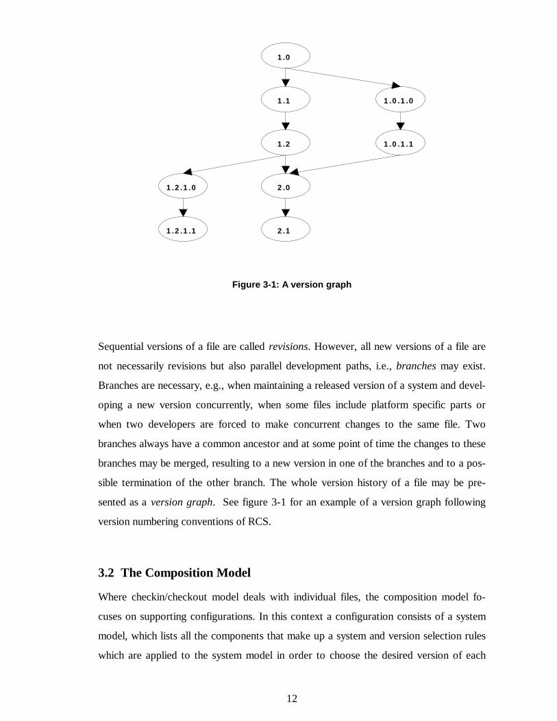
Figure 3-1: A version graph
Sequential versions of a file are called revisions. However, all new versions of a file are
not necessarily revisions but also parallel development paths, i.e., branches may exist.
Branches are necessary, e.g., when maintaining a released version of a system and devel-
oping a new version concurrently, when some files include platform specific parts or
when two developers are forced to make concurrent changes to the same file. Two
branches always have a common ancestor and at some point of time the changes to these
branches may be merged, resulting to a new version in one of the branches and to a pos-
sible termination of the other branch. The whole version history of a file may be pre-
sented as a version graph. See figure 3-1 for an example of a version graph following
version numbering conventions of RCS.
3.2 The Composition Model
Where checkin/checkout model deals with individual files, the composition model fo-
cuses on supporting configurations. In this context a configuration consists of a system
model, which lists all the components that make up a system and version selection rules
which are applied to the system model in order to choose the desired version of each
13
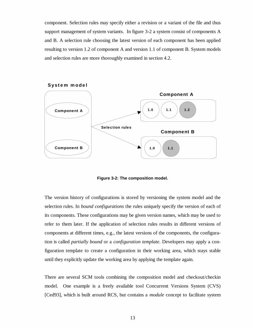
component. Selection rules may specify either a revision or a variant of the file and thus
support management of system variants. In figure 3-2 a system consist of components A
and B. A selection rule choosing the latest version of each component has been applied
resulting to version 1.2 of component A and version 1.1 of component B. System models
and selection rules are more thoroughly examined in section 4.2.
System model
Component A
Component B 1.1
Component A
1.0 1.21.1
1.0
Component BSelection rules
Figure 3-2: The composition model.
The version history of configurations is stored by versioning the system model and the
selection rules. In bound configurations the rules uniquely specify the version of each of
its components. These configurations may be given version names, which may be used to
refer to them later. If the application of selection rules results in different versions of
components at different times, e.g., the latest versions of the components, the configura-
tion is called partially bound or a configuration template. Developers may apply a con-
figuration template to create a configuration in their working area, which stays stable
until they explicitly update the working area by applying the template again.
There are several SCM tools combining the composition model and checkout/checkin
model. One example is a freely available tool Concurrent Versions System (CVS)
[Ced93], which is built around RCS, but contains a module concept to facilitate system

14
modeling. In addition, CVS partially implements the long transaction model discussed in
the next section.
3.3 The Long Transaction Model
The long transaction model focuses on supporting the evolution of the whole system as a
series of apparently atomic changes, and provides team support through coordination of
concurrent change. Developers operate primarily with versioned configurations. In con-
trary to the composition model they first select the version of the system configuration,
and then focus on the system structure. The selected system configuration determines the
versions of the components used. NSE from Sun [Cou89] follows the concepts of this
model.
When making a change a transaction is started. The change is made in a workspace,
which represents the working context and provides local data storage visible only within
the scope of the workspace. A workspace may be mapped into the file system allowing
transparent access to the repository for the development tools. A workspace consists of
a working configuration, where modifications are made and possibly several preserved
configurations, which are frozen states of previous working configurations. A work-
space originates from a bound configuration in the repository or from a preserved con-
figuration of an enclosing workspace. When the changes are finished, the transaction is
committed, which effectively creates a new version of the configuration in the repository
or enclosing workspace and makes the changes visible outside the workspace. Finally the
workspace may be deleted or it may be used for further changes.
If the workspace originates from another workspace, the result is a hierarchy of work-
spaces. The different levels in the hierarchy represent different levels of visibility. The
bottom workspaces belong to the individual developers, one level up is the workspace
for the team and the next level may be visible to the testing team and so on until the hier-
archy ends to the repository.
Three categories of concurrent development is supported:
• concurrency within one workspace,

15
• concurrency between workspaces requiring coordination, and
• concurrent, independent development.
In the first case concurrent changes are restrained by allowing only one person at a time
to change the file. The control may happen at different levels: limiting access to a work-
space to one person; allowing only one person at a time to be active in a workspace; or
locking individual components for exclusive use of one person at a time. In the second
case changes in separate workspaces together evolve the system. Schemes for controlling
this concurrency may be conservative or optimistic. Conservative schemes require a pri-
ori locking across workspaces. In optimistic schemes conflicts are detected when
changes are committed. Third case assumes that system evolves in independent develop-
ment paths and changes need not be coordinated when created.
Figure 3-3 illustrates the concepts of the long transaction model using a simple example.
In the beginning of the first transaction, a working configuration of system version 1.0 is
created into a team workspace. Then a new transaction is started, which creates a new
working configuration to a developer workspace. In the developer workspace some
changes are implemented to the system and working configuration version 2 is created,
making version 1 a preserved configuration. Committing the second transaction creates a
new working configuration to the team workspace and finally committing the first trans-
action creates a new system version to the repository.
R e p o s i t o r y
Systemversion
1.0
Systemversion
1.1
Version 1
Version 2
Begin transaction
Commit transaction
Version 1
Version 2
T e a m w o r k s p a c e
Begin transaction
Commit transaction
D e v e l o p e r w o r k s p a c e
16
Figure 3-3: The long transaction model.
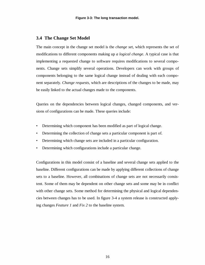
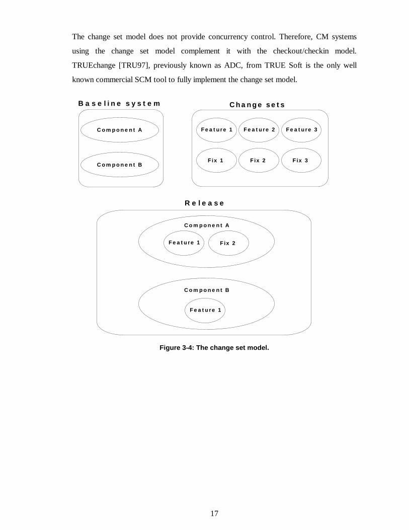
3.4 The Change Set Model
The main concept in the change set model is the change set, which represents the set of
modifications to different components making up a logical change. A typical case is that
implementing a requested change to software requires modifications to several compo-
nents. Change sets simplify several operations. Developers can work with groups of
components belonging to the same logical change instead of dealing with each compo-
nent separately. Change requests, which are descriptions of the changes to be made, may
be easily linked to the actual changes made to the components.
Queries on the dependencies between logical changes, changed components, and ver-
sions of configurations can be made. These queries include:
• Determining which component has been modified as part of logical change.
• Determining the collection of change sets a particular component is part of.
• Determining which change sets are included in a particular configuration.
• Determining which configurations include a particular change.
Configurations in this model consist of a baseline and several change sets applied to the
baseline. Different configurations can be made by applying different collections of change
sets to a baseline. However, all combinations of change sets are not necessarily consis-
tent. Some of them may be dependent on other change sets and some may be in conflict
with other change sets. Some method for determining the physical and logical dependen-
cies between changes has to be used. In figure 3-4 a system release is constructed apply-
ing changes Feature 1 and Fix 2 to the baseline system.
17
The change set model does not provide concurrency control. Therefore, CM systems
using the change set model complement it with the checkout/checkin model.
TRUEchange [TRU97], previously known as ADC, from TRUE Soft is the only well
known commercial SCM tool to fully implement the change set model.
Figure 3-4: The change set model.
Feature 1 Feature 3Feature 2
Fix 1 Fix 3Fix 2
Change setsB a s e l ine s y s t e m
Component A
Component B
R e l e a s e
Component A
Feature 1 Fix 2
Component B
Feature 1
18
4 SCM FUNCTIONALITY AREAS
People having different roles in a software project have different views and expectations
of SCM. The needs of the project manager are very distinct from those of an individual
developer. Susan Dart [Dar91] presents a set of functionalities that project managers,
configuration managers, programmers, testers, QA managers, and customers expect from
a CM system. The functionalities are divided to the team centered functionality areas
dealing with the technical aspects of SCM and the process-centered functionality areas
covering management issues.
Team centered functionality areas are:
• components,
• structure,
• construction, and
• team.
Process centered functionality areas are:
• auditing,
• accounting,
• controlling, and
• process.
A closer overview of the team centered functionalities in today’s SCM systems, follow-
ing the previous classification is presented by Zeller in [Zel96]. He notes that some SCM
aspects, such as variants and distribution, are missing, but the classification is still valid
to capture SCM functionality. A summary of Zeller’s overview is presented in the fol-
lowing sections.
19
4.1 Components
4.1.1 Versioning Dimensions
As discussed earlier, software products are commonly divided into components, which
exist as numerous versions. Versioning can emerge in two dimensions. Succeeding ver-
sions are called revisions and parallel versions created as alternatives to specific versions
are called variants. Variants may be either permanent, e.g., when porting a system to an-
other platform, or temporary, e.g., during the concurrent development of same compo-
nents by different people. Changes made to temporary variants will be finally merged
back to the main development path.
4.1.2 Versioning Models
The most common way to visualize the version history of a component is a version graph
like in figure 3-1. The downward arrows represent the creation of a new revision and
branches emerge in nodes where variants are created. Whether a new version is a variant
or a revision can only be decided afterwards when the later version graph can be in-
spected. The variants are necessary only when more than one version is created based on
the same version of the component. New versioning models have emerged, such as or-
thogonal version management, where all the components, variants, and revisions form a
three dimensional cube, from where projections can be made to select groups of variants,
revisions, or components.
4.1.3 Identification Schemes
Various identification schemes exist for naming new versions of components. Usually
different identification schemes are used for revisions and variants. Increasing revision
numbers are a typical way to identify revisions. A revision number may be a single inte-
ger (1, 2, 3, … ) or a pair of integers (1.0, 1.1, 2.0, … ). In the latter case, the first digit is
a major revision number and the second a minor revision number. They reflect the type
of changes made to a component, major or minor.
20
Variants are usually named instead of numbered, since they are not ordered. One method
is to label the edges in the version graph and identify the desired variant expressing the
path from the root to the branch of the variant. This method forces hierarchical order on
the variants and is restricted to paths in the version graph. Another method is to use at-
tribute/value pairs, where an attribute may, e.g., include the value of the target operating
system. Third method, used especially for temporary variant, is to add numbering levels.
A variant based on version 1.2 may named 1.2.1.1 and the next revision in the new
branch is 1.2.1.2 and so on.
4.1.4 Version Differences
In order to determine version differences, different versions of the component need to be
compared. Tools like UNIX diff are suitable for text files, where common lines are
easily distinguished from differing lines and changes usually affect only small regions.
These tools read two files and generate a set of changes represented as, e.g., editing
commands needed to convert the first file to the second. Binary files, e.g., word proces-
sor documents or image files, are more difficult to process since they usually contain
richer information than plain text. This makes their structure complex and minor logical
changes may affect the contents of the entire file.
4.1.5 Repositories
All the versions of components and metadata pertaining to them are preserved in a place
usually called repository. Metadata includes information such as modification dates,
change history, and author. In order to save space only one complete version and the
differences (deltas) between the versions of the same component need to be stored. If the
complete version is the latest version, reverse deltas are used to generate the older ver-
sions. Correspondingly, if the complete version is the oldest, forward deltas are used to
generate the later versions. As discussed in the previous section the differences between
binary files are difficult to trace. Therefore, the use of deltas is appropriate only for text
files. Much effort has been made to improve the use of databases as repositories.
21
4.1.6 Managing Variance
Variants of a component may also be realized in some programming environments by
building them all inside the same file. This decreases the number of variant source code
components to be managed by the SCM system. The C programming language preproc-
essor can be used to implement this approach. #if and #endif directives inside the source
file may be used to distinguish the lines of the files pertaining to specific variants. Condi-
tional compilation with selected names defined is used thereafter to produce the desired
variant of the system. The control of the variance is in the hands of the programmer. The
advantages are that several variants can be viewed and edited at once, but when rate of
variance increases files become so filled with directives that they are difficult to under-
stand by a human reader. So called multi-variant editors address this problem and try to
alleviate the complexity for instance by using different text coloring indicating whether a
line belongs to one or several variants.
4.2 Structure
4.2.1 System Models
A software system can be described using a system model that identifies its structure and
components, and contains information on how to build the system. The simplest system
model uses is-a-part-of relationships between components to describe the system. More
advanced models are needed to describe the relationships between versions. One of the
first system models including version concepts was AND/OR graphs [Tic81]. In an
AND/OR graph AND nodes model aggregates (systems and subsystems) representing is-
a-part-of relation and OR nodes model version alternatives representing is-a-version-of
relations. AND/OR graphs do not make distinction between revisions and variant. Sev-
eral other models have been presented but they all have both advantages and deficien-
cies.
4.2.2 Configurations
A configuration is identified by configuration rules, which denote the components and
their versions belonging to the configuration. There are three types of configurations. A
22
bound configuration is an unambiguous configuration independent from a specific con-
text, e.g., explicit list of components and their exact versions. A generic configuration is
an unambiguous configuration dependent on the context, e.g., the most recent versions
of the components. In abstract configurations, the rules are ambiguous representing a
set of configurations. Terms like configuration template or configuration family are also
used for such configurations.
A simple way to realize configuration rules is to label specific versions of the compo-
nents using the name of the configuration. More advanced methods use queries made
based on the attribute/value pairs in the component metadata. The query system can be
complemented with preference rules, which are applied if several versions match the
query, and default rules that apply if no version results from the query. In addition, spe-
cific configuration languages, e.g., PCL [Som96] have been developed to integrate some
SCM tasks like system modeling, configurations specification, and manufacturing into
one formalism.
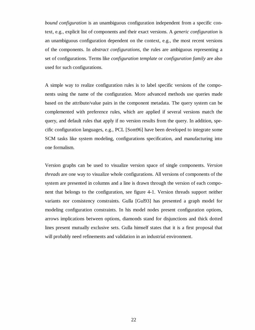
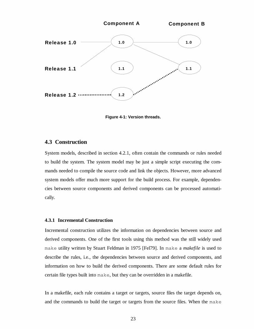
Version graphs can be used to visualize version space of single components. Version
threads are one way to visualize whole configurations. All versions of components of the
system are presented in columns and a line is drawn through the version of each compo-
nent that belongs to the configuration, see figure 4-1. Version threads support neither
variants nor consistency constraints. Gulla [Gul93] has presented a graph model for
modeling configuration constraints. In his model nodes present configuration options,
arrows implications between options, diamonds stand for disjunctions and thick dotted
lines present mutually exclusive sets. Gulla himself states that it is a first proposal that
will probably need refinements and validation in an industrial environment.
23
Figure 4-1: Version threads.
4.3 Construction
System models, described in section 4.2.1, often contain the commands or rules needed
to build the system. The system model may be just a simple script executing the com-
mands needed to compile the source code and link the objects. However, more advanced
system models offer much more support for the build process. For example, dependen-
cies between source components and derived components can be processed automati-
cally.
4.3.1 Incremental Construction
Incremental construction utilizes the information on dependencies between source and
derived components. One of the first tools using this method was the still widely used
make utility written by Stuart Feldman in 1975 [Fel79]. In make a makefile is used to
describe the rules, i.e., the dependencies between source and derived components, and
information on how to build the derived components. There are some default rules for
certain file types built into make, but they can be overridden in a makefile.
In a makefile, each rule contains a target or targets, source files the target depends on,
and the commands to build the target or targets from the source files. When the make
1.0
Component A Component B
Release 1.0
1.1
1.0
1.2
1.1
Release 1.2
Release 1.1
24
command is executed it reads the makefile and builds the target, which is given as an ar-
gument. If no argument is given, target or targets of the first rule are built. If the sources
are derived files the rules for their derivation must exist. An example of a makefile is pre-
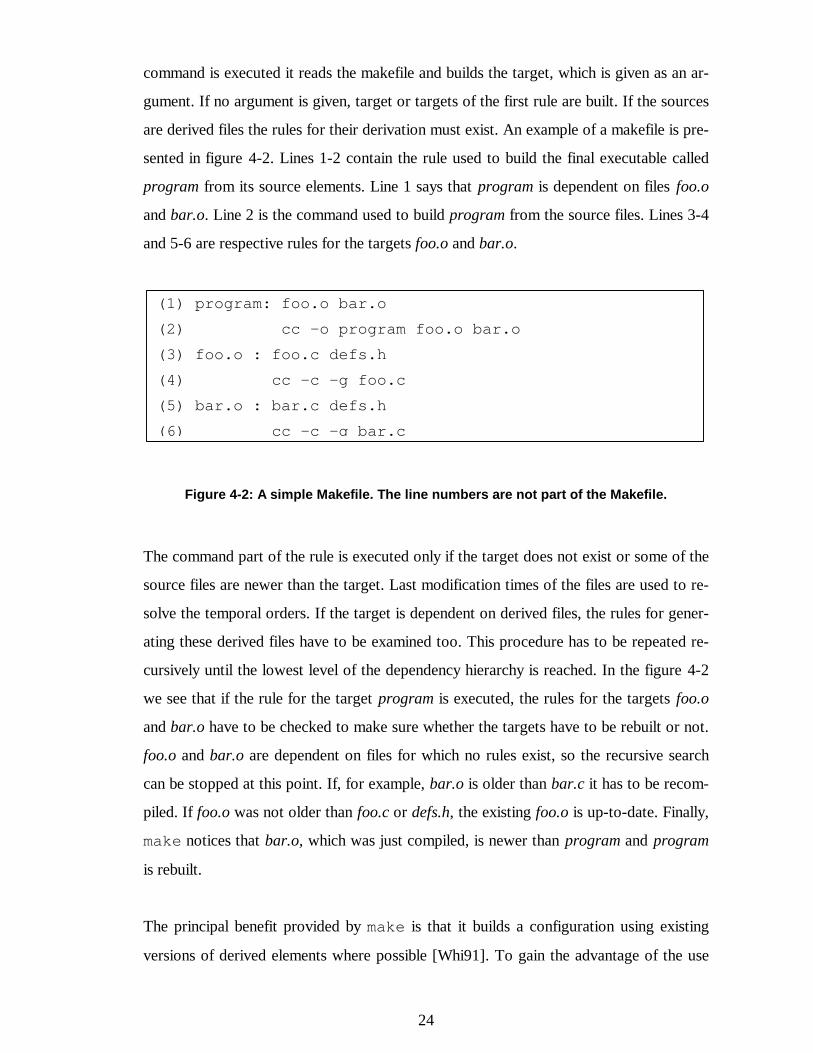
sented in figure 4-2. Lines 1-2 contain the rule used to build the final executable called
program from its source elements. Line 1 says that program is dependent on files foo.o
and bar.o. Line 2 is the command used to build program from the source files. Lines 3-4
and 5-6 are respective rules for the targets foo.o and bar.o.
Figure 4-2: A simple Makefile. The line numbers are not part of the Makefile.
The command part of the rule is executed only if the target does not exist or some of the
source files are newer than the target. Last modification times of the files are used to re-
solve the temporal orders. If the target is dependent on derived files, the rules for gener-
ating these derived files have to be examined too. This procedure has to be repeated re-
cursively until the lowest level of the dependency hierarchy is reached. In the figure 4-2
we see that if the rule for the target program is executed, the rules for the targets foo.o
and bar.o have to be checked to make sure whether the targets have to be rebuilt or not.
foo.o and bar.o are dependent on files for which no rules exist, so the recursive search
can be stopped at this point. If, for example, bar.o is older than bar.c it has to be recom-
piled. If foo.o was not older than foo.c or defs.h, the existing foo.o is up-to-date. Finally,
make notices that bar.o, which was just compiled, is newer than program and program
is rebuilt.
The principal benefit provided by make is that it builds a configuration using existing
versions of derived elements where possible [Whi91]. To gain the advantage of the use
(1) program: foo.o bar.o(2) cc -o program foo.o bar.o(3) foo.o : foo.c defs.h(4) cc -c -g foo.c(5) bar.o : bar.c defs.h(6) cc -c -g bar.c
25
of make the previously built objects have to be stored. Many SCM systems use a cache,
where frequently used derived components are stored even across the building of differ-
ent versions of the system if the components remain unchanged.
Make has some deficiencies:
• It does not address the problem of selecting the right versions of the components to
be processed.
• It does not store the details of the build procedure of the derived elements, e.g., if the
options for the compiler change, make considers the target to be up-to-date.
• It does some unnecessary derivation of files. If changes are made to the comments of
a source file, the target is recompiled. In addition, if some intermediate derived com-
ponents are deleted, like bar.o in figure 4-2, the deleted components and the target
dependent on them are derived when deriving the target even though it was up-to-
date.
• It does not determine the dependencies automatically.
Make has been followed by several build tools, e.g., gmake and imake based on the idea
of make, but addressing the problems explained above.
4.3.2 Determining Dependencies Automatically
Language specific knowledge can be used to deduce dependencies automatically. For
example, in C or C++ languages the source files can be searched for #include directives
based on which the header file dependencies can be extracted. By identifying the changes
pertaining to the comments of the file only or by storing the derivation history across
builds, unnecessary builds can be decreased.
A language independent method is to monitor all file accesses from the build tools and
thus generate the dependencies during the build process. This method may be imple-
mented using a virtual file system.
26
4.3.3 Identification of Derived Items
In addition to the information on the version of the source components, the build envi-
ronment information has to be stored. The versions of the build tools and the parameters
and environment variables used to control them are necessary to produce exact copy of
the derived item later. Some changes in the environment are however such that recom-
pilation is unnecessary. Some tools provide a way to control, which aspects in the envi-
ronment are such that recompilation is necessary.
4.4 Team
Several developers must be able to work concurrently on the same system without inter-
fering each others work. At some point of time, the changes made by individuals have to
be propagated to the other developers. SCM systems provide workspaces as a method of
isolating individuals from each others’ changes and for coordinating the propagation of
changes. A workspace is usually accessed as the file system, so that development tools
can access it directly. There are several ways to implement workspaces and they are dis-
cussed below.
4.4.1 Private Directories
The simplest workspace implementation is copying versions of files between the reposi-
tory and a private storing place in the file system as in the checkout/checkin model. Often
copying the files to be modified is not enough but several other files are needed for com-
pilation, testing and other activities. Instead of copying single files, the whole configura-
tion may be checked out to a workspace. After changes, the repository and private
workspaces must be synchronized by propagating the changes.
This implementation of workspaces is simple but it has several disadvantages. Copying
the whole system to each developer is not realistic for large systems. If developers share
workspaces they must themselves coordinate the concurrent changes to shared files. Files
in the workspace are outside the control of SCM and services of the SCM system.
27
Better methods have been developed that make the workspaces part of the repository
and thus let the developer tools access the repository directly.
4.4.2 Integrating Workspaces and Repositories
One approach to integrate workspaces and repositories is to define standard repositories,
which offer an application programmer interface (API) for tool developers. All tools
should be modified to use this interface instead of the file system to access files. How-
ever, no standard has been adopted by the tool vendors and the file system remains as the
principal access point to the repository.
Virtual file systems are the most successful way to implement transparent access to the
repository. Specific versions of the files may be accessed by embedding the version iden-
tifier to the path of the file, e.g., prog.c:3.1. Workspaces may be defined using configu-
ration rules that select the desired version of each file to be seen in that workspace. No
version information is needed by the tools when accessing files in such workspace. If an
explicit version of a file is needed, embedding the version identifier to the file path over-
rides the configuration rules. ClearCase from Rational [Rat97] implements this kind of
version selection method.
There are three major approaches to realizing virtual file systems. System libraries taking
care of file accesses may be extended to handle version information. Programs needing
access to the repository must be linked anew using new libraries or shared system librar-
ies must be replaced with new ones. The performance of this method is good but relink-
ing the programs may prove to be awkward. Second approach is to place the repository
on a modified network file system (NFS) server. The modified NFS server is easy to de-
ploy but the performance is low especially when compared to direct local file access.
Third approach is to modify the operating system kernel. This implementation is efficient
and transparent to all programs but it may be hard to realize.
28
4.4.3 Cooperation Strategies
When several developers change the same files concurrently, some cooperation strategy
must be followed to avoid problems such as overriding other peoples changes. These
strategies can be divided in two classes: conservative and optimistic. In the conservative
cooperation strategy developers lock the components or configurations they intend to
change. Other developers can not create new revisions of locked files or configurations
but they may start developing a temporary variant, which is seen as a branch in the ver-
sion graph. Instead of using locking a branch may be created immediately. This is desir-
able, e.g., when a long term development effort is initiated and quick changes to the main
development branch should still be possible. Finally, all the changes made in the branches
must be merged with the main branch.
In optimistic strategies all developers have individual temporary variants to work on even
thought the files are shared until they are written in the developers workspace. When
modifications are started, a developer does not have to concern with the creation of a
branch anymore. Again, changes to same files must be merged at some point of time.
This is discussed next.
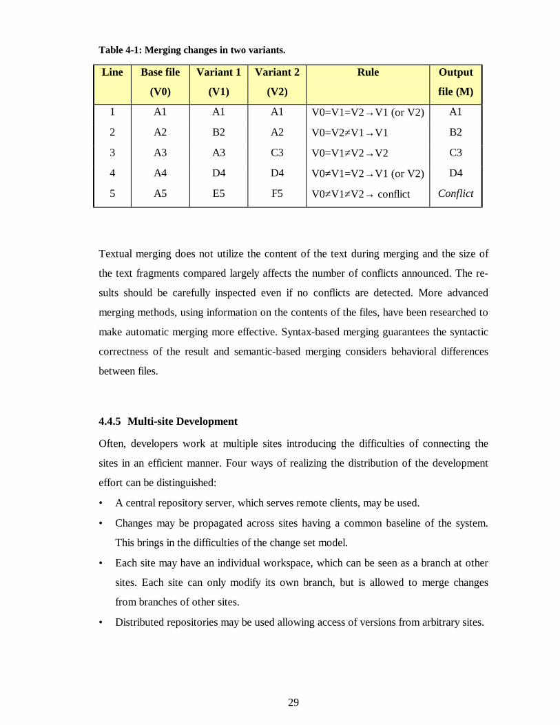
4.4.4 Merging and Conflict Resolution
When a file has been concurrently changed by two or more persons, several variants
having a common ancestor exist and must be integrated to form a new version of the file
including both changes. The most common way is to use textual merging. In the UNIX
system, a tool called diff3 implements a textual merging scheme for two variants. It
scans the variants V1 and V2 and the common ancestor V0 in parallel. If the same text
fragment occurs both in V1 and V2 it is included in the output file M. If a text fragment
differs between V1 and V2, but either one is same as in V0, the changed text fragment is
included in M. If a text fragment is different in V0, V1 and V2, a conflict has been found
which must be solved manually. Table 4-1 presents a simple example of merging two
files.
29
Table 4-1: Merging changes in two variants.
Line Base file
(V0)
Variant 1
(V1)
Variant 2
(V2)
Rule Output
file (M)
1 A1 A1 A1 V0=V1=V2→ V1 (or V2) A1
2 A2 B2 A2 V0=V2≠V1→ V1 B2
3 A3 A3 C3 V0=V1≠V2→ V2 C3
4 A4 D4 D4 V0≠V1=V2→ V1 (or V2) D4
5 A5 E5 F5 V0≠V1≠V2→ conflict Conflict
Textual merging does not utilize the content of the text during merging and the size of
the text fragments compared largely affects the number of conflicts announced. The re-
sults should be carefully inspected even if no conflicts are detected. More advanced
merging methods, using information on the contents of the files, have been researched to
make automatic merging more effective. Syntax-based merging guarantees the syntactic
correctness of the result and semantic-based merging considers behavioral differences
between files.
4.4.5 Multi-site Development
Often, developers work at multiple sites introducing the difficulties of connecting the
sites in an efficient manner. Four ways of realizing the distribution of the development
effort can be distinguished:
• A central repository server, which serves remote clients, may be used.
• Changes may be propagated across sites having a common baseline of the system.
This brings in the difficulties of the change set model.
• Each site may have an individual workspace, which can be seen as a branch at other
sites. Each site can only modify its own branch, but is allowed to merge changes
from branches of other sites.
• Distributed repositories may be used allowing access of versions from arbitrary sites.
30
4.5 Process Centered Functionality Areas
4.5.1 Accounting
Accounting in SCM means recording of statistical information on process and product.
The SCM tools largely determine the available information and the capabilities of the ac-
counting functionality. The process information may include, e.g., time, author, reason,
and description of the implementation of a change. The product information documents
the configuration of each release.
When the data is stored in a form, which allows it to be queried by project personnel it
serves several purposes [Ber92]. When making changes to the software it is often helpful
to refer to the history of the component to be affected. Browsing the previous change
descriptions and problems pertaining to some component may help in the implementation
of new changes and in the evaluation of their impacts. The data can also be used to ana-
lyze and improve the software development process. Measures, like the number of
changes processed per time unit or time spend on implementing changes, can be used to
evaluate the efficiency of the process and as a basis for future work and cost estimates.
Confusion arising from the lack of communication between project personnel is de-
creased when status information like state of the changes and current version of the de-
veloping software is up-to-date and available to everyone.
Reports to be produced should be planned and data necessary for the report generation
should be specified and stored during the project. Many SCM tools automate the gath-
ering of data and provide methods for making queries and generating reports.
4.5.2 Auditing
In the context of SCM three types of audits are performed: functional configuration
audits (FCA), physical configuration audits (PCA), and in-process audits. FCAs and
PCAs are related to the product under development whereas in-process audits pertain to
the SCM processes.
31
FCA is held to ensure that the developed software agrees with the software requirement
specification. It is held late in the project after all the testing has been finished and test
reports are available. The compliance to the requirements is verified by inspecting the
test report data and comparing it to the software requirements. Where the requirements
have not been met, a suggested solution should be presented.
PCA usually takes place after FCA. Its purpose is to verify that all documentation and
source code correspond to each other and they follow the specified documentation stan-
dards. The solutions to failures noted in FCA should also be verified.
In-process audits are conducted to ensure that rational SCM processes exist and they are
followed as documented. In-process audits may also contribute to the improvement of
the SCM processes.
4.5.3 Controlling
Controlling functionality covers the activities involved in controlling changes. Changes
are unavoidable in the real world for many reasons as discussed in section 2.1. However,
well-organized and disciplined change control procedures are necessary to preserve the
integrity of the product during its development and maintenance. Change control is often
seen hindering and slowing an engineer doing his work and it is true that he or she has to
do more that just implement the modification. Change control requires the engineer to
work in a responsible and disciplined way which contributes to the overall objectives of
the team [Whi91]. The effort used in this bureaucracy is however paid back when the
confusion caused by sudden changes diminishes, quality of released products improves
and state of the product and the development process becomes more visible.
Change process begins when a need for a change occurs. The proposer of the change fills
a change request (CR) form describing the change, the reason for it, and the items and
their versions to be changed. Each CR should also get an identification number. CRs go
through the whole change process and are complemented with more information in each
stage.
32
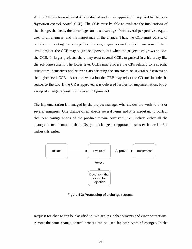
After a CR has been initiated it is evaluated and either approved or rejected by the con-
figuration control board (CCB). The CCB must be able to evaluate the implications of
the change, the costs, the advantages and disadvantages from several perspectives, e.g., a
user or an engineer, and the importance of the change. Thus, the CCB must consist of
parties representing the viewpoints of users, engineers and project management. In a
small project, the CCB may be just one person, but when the project size grows so does
the CCB. In larger projects, there may exist several CCBs organized in a hierarchy like
the software system. The lower level CCBs may process the CRs relating to a specific
subsystem themselves and deliver CRs affecting the interfaces or several subsystems to
the higher level CCBs. After the evaluation the CBB may reject the CR and include the
reason to the CR. If the CR is approved it is delivered further for implementation. Proc-
essing of change request is illustrated in figure 4-3.
The implementation is managed by the project manager who divides the work to one or
several engineers. One change often affects several items and it is important to control
that new configurations of the product remain consistent, i.e., include either all the
changed items or none of them. Using the change set approach discussed in section 3.4
makes this easier.
Initiate Evaluate Implement
Document the reason for rejection
Reject
Approve
Figure 4-3: Processing of a change request.
Request for change can be classified to two groups: enhancements and error corrections.
Almost the same change control process can be used for both types of changes. In the
33
case of an error, an additional investigation is performed to identify the cause for the er-
ror, and to make a proposal for a fix and a cost estimation for fixing the error.
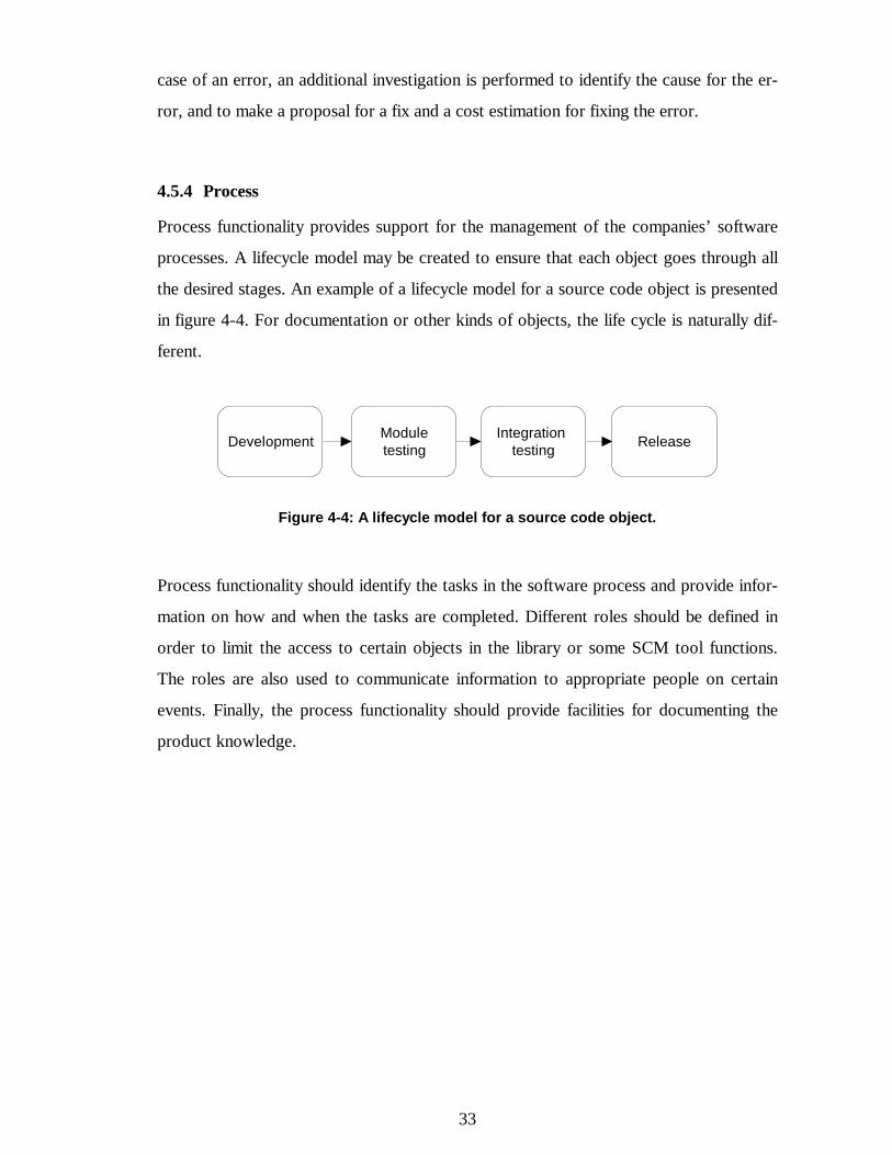
4.5.4 Process
Process functionality provides support for the management of the companies’ software
processes. A lifecycle model may be created to ensure that each object goes through all
the desired stages. An example of a lifecycle model for a source code object is presented
in figure 4-4. For documentation or other kinds of objects, the life cycle is naturally dif-
ferent.
Development Module testing
Integration testing Release
Figure 4-4: A lifecycle model for a source code object.
Process functionality should identify the tasks in the software process and provide infor-
mation on how and when the tasks are completed. Different roles should be defined in
order to limit the access to certain objects in the library or some SCM tool functions.
The roles are also used to communicate information to appropriate people on certain
events. Finally, the process functionality should provide facilities for documenting the
product knowledge.
34
5 ADOPTING SCM
In the past, no third party SCM tools were available. If organizations used configuration
management and wanted to automate the processes, they had to develop systems in-
house either from scratch or based on version control facilities provided by operating
system vendors, e.g., SCCS with UNIX. Manual procedures and policies were part of
most SCM solutions [Dar92].
Today, the situation is completely different. There are many SCM tools covering the
needs of organizations aiming at automated configuration management. During the nine-
ties, the tools have also matured significantly in terms of increased functionality, im-
proved usability and reliability, and broader platform coverage [Bur96]. When an organi-
zation begins to improve its configuration management issues, purchasing a modern
SCM tool is the foundation on which the new processes can be built. However, the se-
lection of the tool should be done with care and be based on the needs of the organiza-
tion and its overall SCM solution. The adopted processes should determine the tool, not
vice versa.
A guide for a SCM improvement project, from the initial realizing of the need for SCM
to the final deployment of new CM processes, is presented in [Bur96] and the following
sections are based on it. The approach in this guide is rather tool centered and very ho-
listic concerning all areas of SCM. Following it is a long and tedious project. This kind of
approach may not be the best one for a smaller organization or for an organization,
whose other software development processes are immature. An alternative way would be
incremental building of the SCM environment starting from the basic version control fa-
cilities, and later adding the more advanced functionalities. Models for incremental SCM
development has been presented in [Aue95] and [Sha97]. The justification behind the
incremental approach is to avoid the difficulties of implementing a full-fledged SCM so-
lution by dividing it to small stages. In the incremental model, one concentrates first on
the most fundamental tasks, which are the prerequisites for later stages, and then goes on
step by step. This approach provides results faster and allows an immature organization
35
to improve its SCM processes simultaneously with other software development proc-
esses.
5.1 Initiating a SCM Improvement Project
Often organizations awake on considering the improvement of their SCM processes only
when the problems originating from the lack of SCM start seriously affecting their func-
tioning. There are several reasons for starting to improve the SCM processes and starting
to find a new SCM tool:
• Increase of errors in released product such as wrong versions of components or old
errors reappearing.
• Old or manual SCM processes may be too bureaucratic to be followed without a
considerable negative effect on time used on real work.
• A new project, including people having good experience on some SCM tools, is
started and they want to adopt that tool to the project.
• Customer’s demands for organizing SCM.
• Rising the company image by fulfilling the requirements of quality standards such as
ISO 9000 or Capability Maturity Model (CMM) [Pau93].
The specific reasons why an organization starts a SCM improvement project should be
documented clearly to facilitate understanding of the SCM needs and finding of the best
solution.
In order to start a SCM project four issues need to be addressed:
• The people affected by the new tool recognize the current problems in SCM.
• The people recognize the benefits of change.
• The management is committed to the change.
• The selection and deployment of the new tool is organized and led by a knowledge-
able person or team.
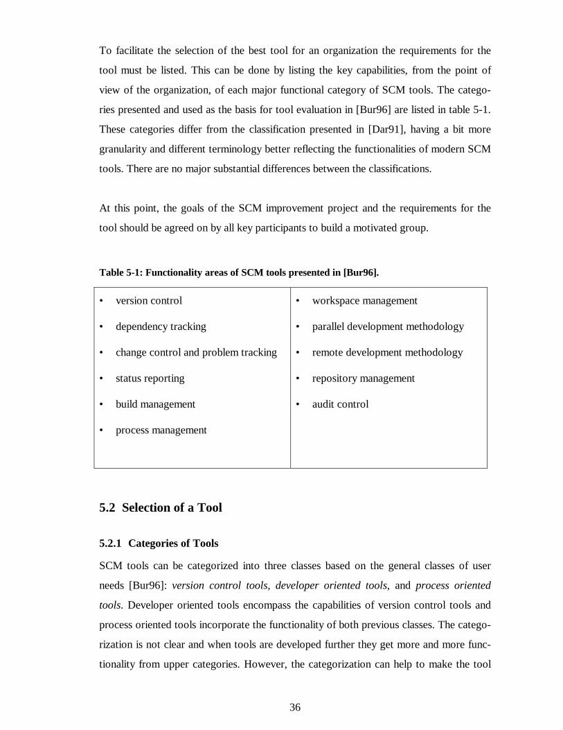
36
To facilitate the selection of the best tool for an organization the requirements for the
tool must be listed. This can be done by listing the key capabilities, from the point of
view of the organization, of each major functional category of SCM tools. The catego-
ries presented and used as the basis for tool evaluation in [Bur96] are listed in table 5-1.
These categories differ from the classification presented in [Dar91], having a bit more
granularity and different terminology better reflecting the functionalities of modern SCM
tools. There are no major substantial differences between the classifications.
At this point, the goals of the SCM improvement project and the requirements for the
tool should be agreed on by all key participants to build a motivated group.
Table 5-1: Functionality areas of SCM tools presented in [Bur96].
• version control
• dependency tracking
• change control and problem tracking
• status reporting
• build management
• process management
• workspace management
• parallel development methodology
• remote development methodology
• repository management
• audit control
5.2 Selection of a Tool
5.2.1 Categories of Tools
SCM tools can be categorized into three classes based on the general classes of user
needs [Bur96]: version control tools, developer oriented tools, and process oriented
tools. Developer oriented tools encompass the capabilities of version control tools and
process oriented tools incorporate the functionality of both previous classes. The catego-
rization is not clear and when tools are developed further they get more and more func-
tionality from upper categories. However, the categorization can help to make the tool
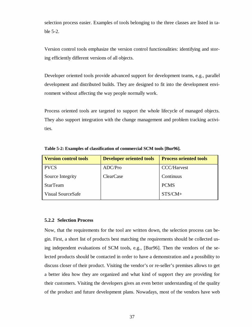
37
selection process easier. Examples of tools belonging to the three classes are listed in ta-
ble 5-2.
Version control tools emphasize the version control functionalities: identifying and stor-
ing efficiently different versions of all objects.
Developer oriented tools provide advanced support for development teams, e.g., parallel
development and distributed builds. They are designed to fit into the development envi-
ronment without affecting the way people normally work.
Process oriented tools are targeted to support the whole lifecycle of managed objects.
They also support integration with the change management and problem tracking activi-
ties.
Table 5-2: Examples of classification of commercial SCM tools [Bur96].
Version control tools Developer oriented tools Process oriented tools
PVCS
Source Integrity
StarTeam
Visual SourceSafe
ADC/Pro
ClearCase
CCC/Harvest
Continuus
PCMS
STS/CM+
5.2.2 Selection Process
Now, that the requirements for the tool are written down, the selection process can be-
gin. First, a short list of products best matching the requirements should be collected us-
ing independent evaluations of SCM tools, e.g., [Bur96]. Then the vendors of the se-
lected products should be contacted in order to have a demonstration and a possibility to
discuss closer of their product. Visiting the vendor’s or re-seller’s premises allows to get
a better idea how they are organized and what kind of support they are providing for
their customers. Visiting the developers gives an even better understanding of the quality
of the product and future development plans. Nowadays, most of the vendors have web
38
sites containing up-to-date information of their products. Visiting these web sites is an
easy and quick way to gather information on a large number of products.
Some users, who use the product in an environment similar to the intended, should be
visited. The users should be asked why they chose the product, what other products they
were investigating, what are the likes and dislikes in the product, and how did the imple-
mentation go. It is better to discuss with the users without the presence of the vendor’s
agent to get comments that are more truthful.
When the short list of the products has been overhauled, it is time to make the decision.
The key players of the SCM project should rank the products and if it seems that some
product ranks low in everyone’s list it can be rejected. If some product is a clear winner
it should be selected and the reasons why key players ranked it high should be docu-
mented.
If there are still several contenders, the products should be ranked in relation to each rea-
son why the organization is purchasing a SCM tool. This shows the strengths and weak-
nesses of each product in the intended use. If there are still several products, the key
players should be allowed to bring a couple of other factors into discussion. Finally, there
is a winner or else the products are so close to each other that the decision can be made
on the basis of the price. In the latter case the decision may also be given to the devel-
opers who will first use the system in order to motivate them by giving them the feeling
that they chose the product. Again the reasons why a specific product was chosen should
be documented and agreed on by each key player.
5.3 Implementation
When the product has been selected, it must be embedded into the organization’s envi-
ronment. The product must be customized to support the organization’s processes and,
on the other hand, organization’s processes have to be refined to take advantage of the
automation and other possibilities provided by the tool. The initial customizations should
be assigned to the supplier’s staff because it is usually more experienced, providing a
more reliable installation more quickly and probably even more cheaply. If the supplier
39
makes the customizations, they also have the responsibilities to fix the problems if the
system does not work as expected.
The deployment instructions in [Bur96] are based on Susan Dart’s paper Adopting An
Automated Configuration Management Solution [Dar95]. Risk reduction is the central
concern in deployment meaning that the risks, which are the critical success factors for
deployment, should be addressed and mitigating them is the best way of eliminating re-
sistance to change. A checklist of critical success factors pertaining to issues in planning,
process, culture, roles, risk management, environment, applications, requirements and
management, is presented in [Bur96].
The adoption strategy consists of five phases:
• Analysis and planning. Doing the preparation, analysis and scheduling required to
begin deployment. Writing an adoption plan and a risk management plan.
• Process refinement. Understanding existing CM processes and refining them or de-
fining new ones. Writing a CM process model document and CM process imple-
mentation plan document.
• Piloting. Mitigating the risks through pilot project or projects.
• Rolling out. Writing a roll out plan for each group and rolling out the new CM solu-
tion to each group.
• Process improvement. Capturing lessons learned from the deployment and planning
for continuous improvement.
The deployment should be started only when everything is ready. Problems may cause
users to lose the confidence on the new system. The deployment should be monitored
closely, reacting to the feedback from the users. If early users are pleased, the system is
easier to market to the other groups. Finally, when the system is fully deployed, metrics
should be monitored to see if the anticipated improvements have realized.
40
6 IMPLEMENTING SCM PROCESSES OF THE HANSA SOFTWARE
6.1 Overview of the Hansa Software Development Process
6.1.1 Introduction
Hansa is a software system for supporting business functions such as managing informa-
tion pertaining to, e.g., sales, purchases, and stores. Its users range from small companies
to large organizations such as the material acquisition department of the city of Tampere.
Hansa has been developed over ten years reaching version number 6.1. Currently about
ten persons are involved in the development and maintenance of the software and about
the same number of persons are managing customer support and training. During the
years, Hansa has been delivered to over 250 customers.
6.1.2 Structure
The system is implemented using the COBOL programming language. COBOL is a ma-
ture language developed in the fifties especially for writing software to support business
functions.
The source code of the latest Hansa version consists of little bit more than 10 000 ordi-
nary COBOL source files, which are rather small, typically ranging from 50 to 200 lines
of text. In addition, there are about 1000 so called CP-files corresponding to the execu-
table programs in the system. CP-files use ordinary COBOL source files by including
them through COPY statements. Included files may further include other files. Typically,
one CP-file uses dozens of other COBOL files making the dependencies between source
files rather complex.
Source code files are organized into over a hundred subdirectories created in accordance
with the subsystems and high level functionalities of the software. Some subdirectories
exist for common files used by several subsystems. The subdirectories do not contain
other subdirectories.
41
6.1.3 Versioning
Basic system functionality is provided by a base system, which can also be sold as such.
However, most of the delivered systems are customer systems. They are customized
separately for each customer, on source code level, resulting in a large number of parallel
versions, i.e., variants of the system. Naturally, the base system has been developed con-
stantly and it exists in several major versions. Most of the customers have systems based
on one of the three latest versions of the base system. The older major versions are
maintained as long as all customers have upgraded their system to a newer version.
Major versions of the base system have been released at most once a year and they may
include larger changes to the system, e.g., changes to data fields. Therefore, upgrading to
a new major version of the system requires creation and execution of conversion pro-
grams to move existing customer data into the form the new version uses. Smaller
changes are made and released constantly. They are installed simply by replacing the
changed program files or other files with the new ones at the customer site.
Only the major versions of the base system are managed separately. Source code for each
major version is placed in a directory named after the version number of the system.
None of the version directories do not have to and, actually, do not include the whole
source code. When compiling a specific version of the system, source code files are first
searched from the directory of the desired version. If some file is missing, the directory
for the previous major version is searched using compiler features and so on until the file
is found. This method is used in order to reduce the amount of work required, when
making a change that should be implemented to all or several major versions. If there has
not been version specific changes to a file in couple of latest versions, the file does not
exist in those directories. When a change is implemented in the latest version, where the
file is found, it becomes visible in all newer versions, too.
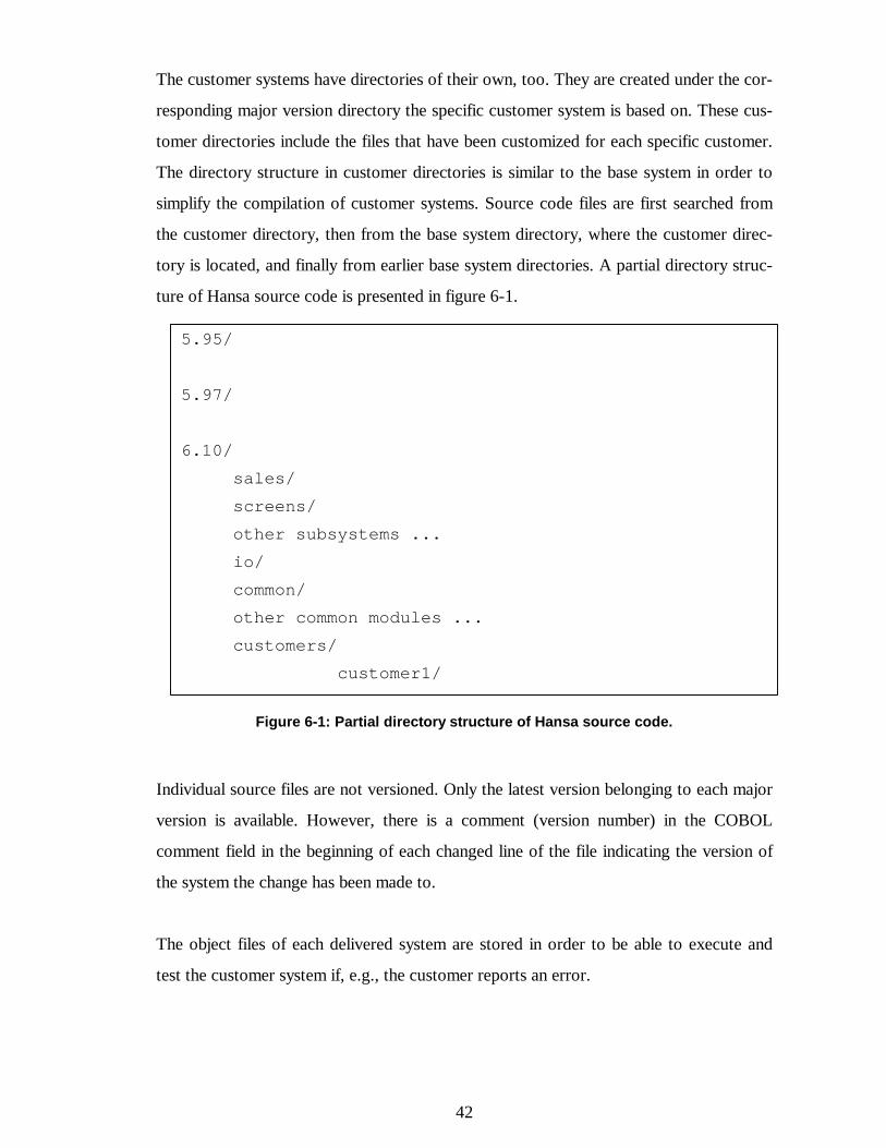
42
The customer systems have directories of their own, too. They are created under the cor-
responding major version directory the specific customer system is based on. These cus-
tomer directories include the files that have been customized for each specific customer.
The directory structure in customer directories is similar to the base system in order to
simplify the compilation of customer systems. Source code files are first searched from
the customer directory, then from the base system directory, where the customer direc-
tory is located, and finally from earlier base system directories. A partial directory struc-
ture of Hansa source code is presented in figure 6-1.
Figure 6-1: Partial directory structure of Hansa source code.
Individual source files are not versioned. Only the latest version belonging to each major
version is available. However, there is a comment (version number) in the COBOL
comment field in the beginning of each changed line of the file indicating the version of
the system the change has been made to.
The object files of each delivered system are stored in order to be able to execute and
test the customer system if, e.g., the customer reports an error.
5.95/
5.97/
6.10/sales/screens/other subsystems ...io/common/other common modules ...customers/
customer1/
43
6.1.4 Development process
The development consists of four main categories:
• Adding new features to the base version,
• adding new features to customer systems,
• upgrading customer systems to the latest version, and
• fixing bugs.
A request for a change may come either from a customer or in-house and it may be any-
thing from a minor bug fix to a large customization project requiring weeks of work. In
any case, finally, a work specification is created to the AsiakasPalveluKanta (APK). The
APK is an in-house developed software application used for several purposes such as
delegating work inside the company and monitoring resources used in different tasks.
The APK form contains the necessary information to manage the programming. It is sent
to the main programmer, who may make some technical refinements to the work specifi-
cation. Finally, the main programmer issues it to a programmer, who will be responsible
for the work. When the programmer finishes his work, he writes a program document
that includes, e.g., a list of changed files and a closer description of the change. This
document is linked to the APK form. Then the APK form is issued to the person respon-
sible for testing the change. If the change is a customer specific change the same person,
who tests it, delivers it to the customer.
6.2 Problems in the Current Development Process
There are several known problems in the current development process. Those initiated
mainly from the insufficient attention to configuration management issues are described
below.
The propagation of changes from one customer system to another or from the base sys-
tem to customer systems is laborious. Often, when a change, e.g., a bug fix is made to
the base system it is desirable that it is also propagated to the customer systems. How-
ever, in order to propagate the changes, the developer has to search all customer directo-
ries for variants of the files and copy the changes to them. There is no easy way to handle
44
all the variants and revisions of an individual file. Usually, there is no time to do this
work. Even if the changes were propagated to customers’ source codes there still re-
mains the effort required to deliver the changes.
The exact source code for a specific release can not be retrieved, because frozen version
are not made. Only the object code is preserved. Each major version of the system has its
own directory but inside the directory, the development continues and the current source
code in a directory represents the latest source code for that version. Whenever a change
is made to a file the older version is lost forever.
It is hard to trace whether a proposed change has already been made to some customer
system. The problem is emphasized by the fact that a bug fix is usually implemented and
delivered to a specific customer only when the customer finds the problem. This is due to
the previously mentioned problems in change propagation. This may lead to the imple-
mentation of the same changes several times and probably in a different way.
6.3 Proposed SCM Tasks
The author discussed with the development director and the main programmer of the
company about the Hansa product, the development process and SCM issues. Based on
the information acquired from these discussions and from some product and process
documentation, a proposal was made for the most important actions necessary to im-
prove the configuration management processes pertaining to the development and main-
tenance of the Hansa product. The content of the proposal is summarized below.
6.3.1 Source Code Control
Versioning
Starting the version management of the source code is one of the most important actions
to do. The versioning should cover individual files, the base system, and customer sys-
tems. A new version of a file is created whenever a developer finishes implementing a
change to it. The base system or a customer system is assigned a version number when it
45
is released to a customer, or when some larger changes are made. Assigning a version
number implicitly supposes that exact versions of the files belonging to the system ver-
sion can be retrieved later. This requires some accounting, e.g., giving a common label to
the desired versions of the files or maintaining a separate list of files and their versions
belonging to a specific system version.
The source code of the base system, currently spread in directories of several major ver-
sions, must be gathered under the directory tree of the latest major version. Thereafter,
the latest version may act as a starting point and version 1.0 for version control and it
can be taken under the control of some SCM tool.
For several reasons, supporting the versioning of older versions is not worth the in-
creased complexity and required effort. First, most of the development takes place in the
latest version. Secondly, most of the customers will update to the latest version because
of the changes needed to conform to the new requirements of EMU. Thus, the mainte-
nance effort of older versions reduces all the time. Thirdly, no SCM tool has been previ-
ously in use and only the latest version instead of a complete history of each file belong-
ing to a specific major version exists.
Customizations
To manage the existing customer systems with a SCM tool they have to be updated to
the latest version of the base system and then taken under version control. The updating
work can be done with moderate effort for customer systems based on the two latest
versions (55 customers) but updating older ones requires more effort. However, incorpo-
rating the old customer systems under the SCM tool may be done one system at a time,
e.g., when a customer orders an upgrade.
When a file has to be customized, a new branch is created in its version tree to support
the parallel development and maintenance of customer systems. The version tree of a file
includes as many branches as there are customization of that file (customer branches)
plus one for the base version (base branch). The naming of the branches may follow the
46
naming of customer systems. At least some convention has to be used to name the
branches in different files belonging to one customer system consistently.
Changes
The changes to be made to the system can be classified in two groups: common changes
and customer specific changes. Customer specific changes are simply implemented to the
customer’s branch of the files. Common changes require more attention.
Common changes are those implemented to the base system. Usually they should be
propagated to all customer systems. Since the systems are built from the same source
code, this happens automatically, unless there exists branches in the version trees of the
changed files. In that case, the changes have to be copied to the branches. This means
that a merge operation supported by most SCM tools should be executed. If the changes
made in the branch are not physically in conflict with those in the base branch the merg-
ing may be done automatically. A physical conflict means that same lines of code are
changed in both branches. The result of automatic merging should always be reviewed,
because SCM tools do not typically notice logical dependencies between changes.
If a common change has such considerable effects on the system that it should not auto-
matically be part of the customer systems, it should be implemented to a new major ver-
sion of the base system.
Figure 6-2 presents a sample version tree of a file that has been customized to two cus-
tomers. It includes all the different cases when a new version of a file emerges. The ex-
planations are given below. Numbers correspond to those in parentheses in figure 6-2.
1. A common change is implemented resulting to a new version in the base branch.
2. A customer specific change for customer A is made. A new branch is started because
the file has not already been customized for this customer.
3. A common change is propagated to customer A. It requires a merge operation be-
tween versions 1.2 and A1.0.
4. A customer specific change for customer B is made.
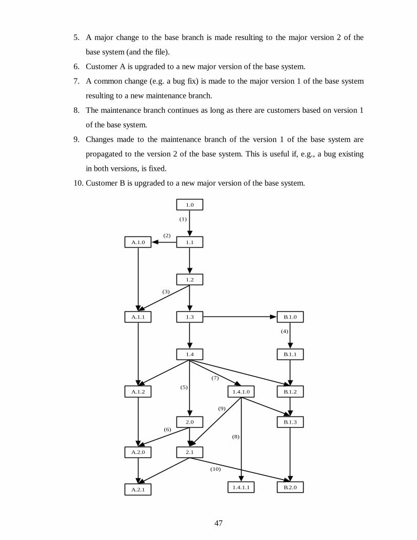
47
5. A major change to the base branch is made resulting to the major version 2 of the
base system (and the file).
6. Customer A is upgraded to a new major version of the base system.
7. A common change (e.g. a bug fix) is made to the major version 1 of the base system
resulting to a new maintenance branch.
8. The maintenance branch continues as long as there are customers based on version 1
of the base system.
9. Changes made to the maintenance branch of the version 1 of the base system are
propagated to the version 2 of the base system. This is useful if, e.g., a bug existing
in both versions, is fixed.
10. Customer B is upgraded to a new major version of the base system.
1.0
1.3
1.2
1.1
B.1.0
A.1.2
A.1.1
A.1.0
1.4
B.1.2
B.1.1
A.2.0
2.0
(1)
(2)
(3)
(4)
(5)
(6)B.1.3
1.4.1.0
A.2.1
2.1
B.2.0
(7)
(8)
1.4.1.1
(9)
(10)
48
Figure 6-2: A sample version graph of a source file.
Typically, one logical change affects several files. Some kind of grouping of files be-
longing to a logical change would be helpful.
Special files
There are some special files like the configuration files for screens, forms and menus in
the system, which are hard to manage. This is because they may be changed, in addition
to the developers, also by the customer support personnel or even by the customers
themselves. If the customer is allowed to make these modifications, it is very hard to put
any control on them. The changes made to these files by developers after the initial deliv-
ery of the system are unusual so they can be left out of SCM control without major in-
conveniences.
6.3.2 Problem Reports and Change Requests
Problem reports and change requests may be managed using the APK system as before.
The APK has some deficiencies and developing it further would be useful. For example,
when a new change request emerges, a query whether a similar change has already been
implemented for some customer is now difficult to make but would be a very useful fea-
ture. The integration issues between the APK and the SCM tool should be considered,
e.g., a linkage between an APK form and a change description in SCM tool.
6.3.3 Documentation
User manual should be taken under version control and the manual should be updated at
least when major changes are made to the base system.
A program document has previously been written for each change in order to preserve
some change history of the system. A SCM tool may provide much of the required in-
49
formation and either automatic generation of program documents or another way to
store the information might be possible.
6.3.4 Other Tasks
In order to successfully deploy the new SCM processes a person inside the company
should be named responsible for SCM issues. He should also be responsible for writing a
plan, which covers responsibilities and resources pertaining to the execution of SCM
processes and precise instructions for SCM activities.
6.4 Selection of a Tool
There was no SCM tool in use and there was no previous experience on SCM tools in
the company. The need for a tool was apparent and the author began to look for a suit-
able one for the needs of CompuPro.
6.4.1 Selection Criteria
Criteria for the tool selection were based on the issues presented in the previous sections
and on general evaluating properties of SCM tools, taking into consideration the issues
in Hansa development. The specific operations were adjusted so that they could be di-
rectly mapped to operations commonly provided by SCM tools. These operations are
listed in table 6-1.
Evaluated properties were based on a report Ovum Evaluates: Configuration Manage-
ment Tools [Bur96], where capabilities and properties that could be assumed from mod-
ern SCM tools are listed and described. The evaluated properties are listed in table 6-2.
Capabilities were evaluated in a meeting with the development director of CompuPro
and classified into four categories: essential, useful, little significance, or no significance.
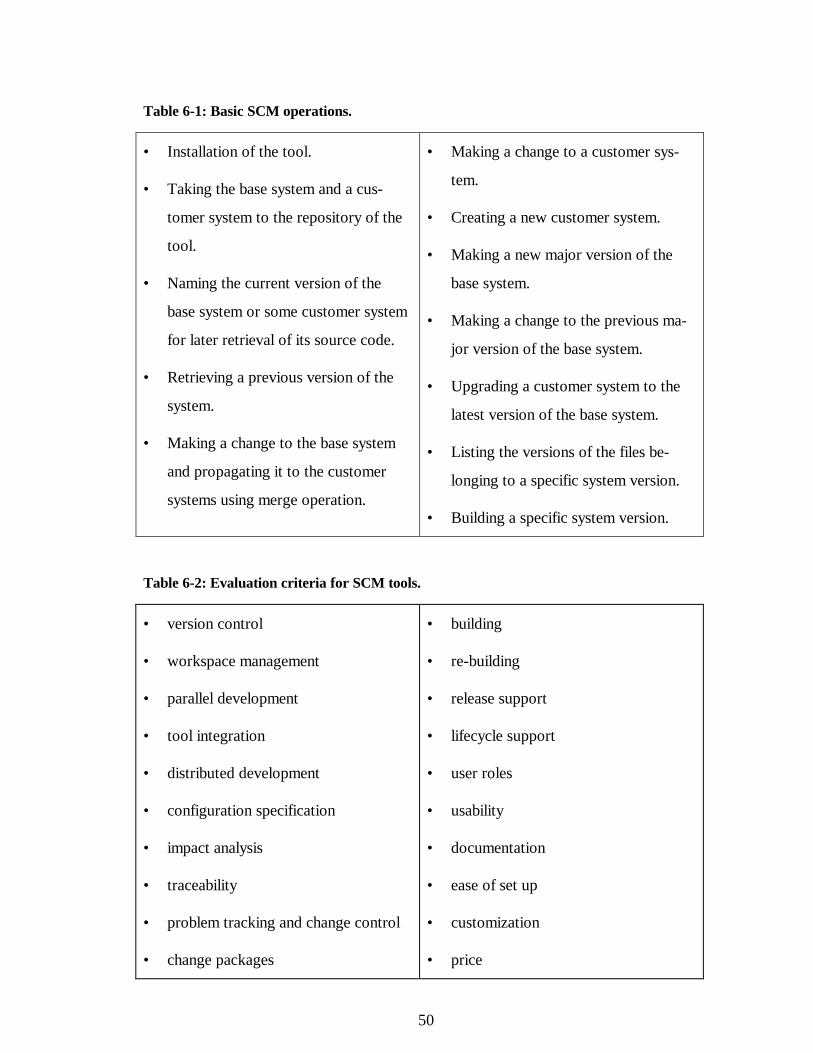
50
Table 6-1: Basic SCM operations.
• Installation of the tool.
• Taking the base system and a cus-
tomer system to the repository of the
tool.
• Naming the current version of the
base system or some customer system
for later retrieval of its source code.
• Retrieving a previous version of the
system.
• Making a change to the base system
and propagating it to the customer
systems using merge operation.
• Making a change to a customer sys-
tem.
• Creating a new customer system.
• Making a new major version of the
base system.
• Making a change to the previous ma-
jor version of the base system.
• Upgrading a customer system to the
latest version of the base system.
• Listing the versions of the files be-
longing to a specific system version.
• Building a specific system version.
Table 6-2: Evaluation criteria for SCM tools.
• version control
• workspace management
• parallel development
• tool integration
• distributed development
• configuration specification
• impact analysis
• traceability
• problem tracking and change control
• change packages
• building
• re-building
• release support
• lifecycle support
• user roles
• usability
• documentation
• ease of set up
• customization
• price
51
• reports and metrics • customer support
6.4.2 Evaluating Tools
The SCM tool selection process was split in three stages:
1. A survey of available tools.
2. An in-depth survey of some tools.
3. The selection of the best tool based on the evaluation criteria.
Survey of Available Tools
The most important source of information was the report Ovum Evaluates: Configura-
tion Management [Bur96]. It provides an in-depth evaluation of ten leading SCM tools
and key features of further 22 CM related products. Additional information was acquired
from the Internet. A frequently asked questions (FAQ) file from the Internet newsgroup
comp.software.config-mgmt contains an up-to-date list of available SCM tools and links
to the WWW homepages of the vendors. The marketing information provided by the
vendors was mostly acquired through the WWW. The same FAQ file contained results
from an Internet user survey on SCM tools. Based on all the available information five
tools that appeared to be suitable for CompuPro’s purposes or had received good
evaluations were chosen for in-depth survey. Tools selected for in-depth survey were:
• ClearCase from Rational,
• Perforce from Perforce Software,
• PVCS from Intersolve,
• Source Integrity from MKS, and
• Visual SourceSafe from Microsoft.
In-depth Survey
The in-depth survey was conducted by obtaining an evaluation version of the tools2 and
using the tools in a simulated development environment. First, a rough understanding of
2 An evaluation version of ClearCase was not available but their re-seller organized a demonstration.
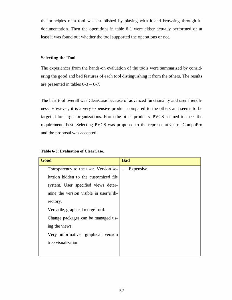
52
the principles of a tool was established by playing with it and browsing through its
documentation. Then the operations in table 6-1 were either actually performed or at
least it was found out whether the tool supported the operations or not.
Selecting the Tool
The experiences from the hands-on evaluation of the tools were summarized by consid-
ering the good and bad features of each tool distinguishing it from the others. The results
are presented in tables 6-3 – 6-7.
The best tool overall was ClearCase because of advanced functionality and user friendli-
ness. However, it is a very expensive product compared to the others and seems to be
targeted for larger organizations. From the other products, PVCS seemed to meet the
requirements best. Selecting PVCS was proposed to the representatives of CompuPro
and the proposal was accepted.
Table 6-3: Evaluation of ClearCase.
Good Bad
+ Transparency to the user. Version se-
lection hidden to the customized file
system. User specified views deter-
mine the version visible in user’s di-
rectory.
+ Versatile, graphical merge-tool.
+ Change packages can be managed us-
ing the views.
+ Very informative, graphical version
tree visualization.
− Expensive.
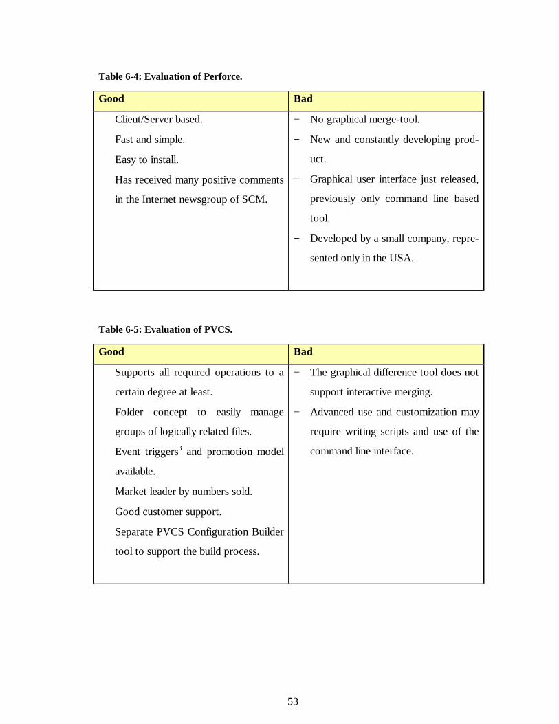
53
Table 6-4: Evaluation of Perforce.
Good Bad
+ Client/Server based.
+ Fast and simple.
+ Easy to install.
+ Has received many positive comments
in the Internet newsgroup of SCM.
− No graphical merge-tool.
− New and constantly developing prod-
uct.
− Graphical user interface just released,
previously only command line based
tool.
− Developed by a small company, repre-
sented only in the USA.
Table 6-5: Evaluation of PVCS.
Good Bad
+ Supports all required operations to a
certain degree at least.
+ Folder concept to easily manage
groups of logically related files.
+ Event triggers3 and promotion model
available.
+ Market leader by numbers sold.
+ Good customer support.
+ Separate PVCS Configuration Builder
tool to support the build process.
− The graphical difference tool does not
support interactive merging.
− Advanced use and customization may
require writing scripts and use of the
command line interface.
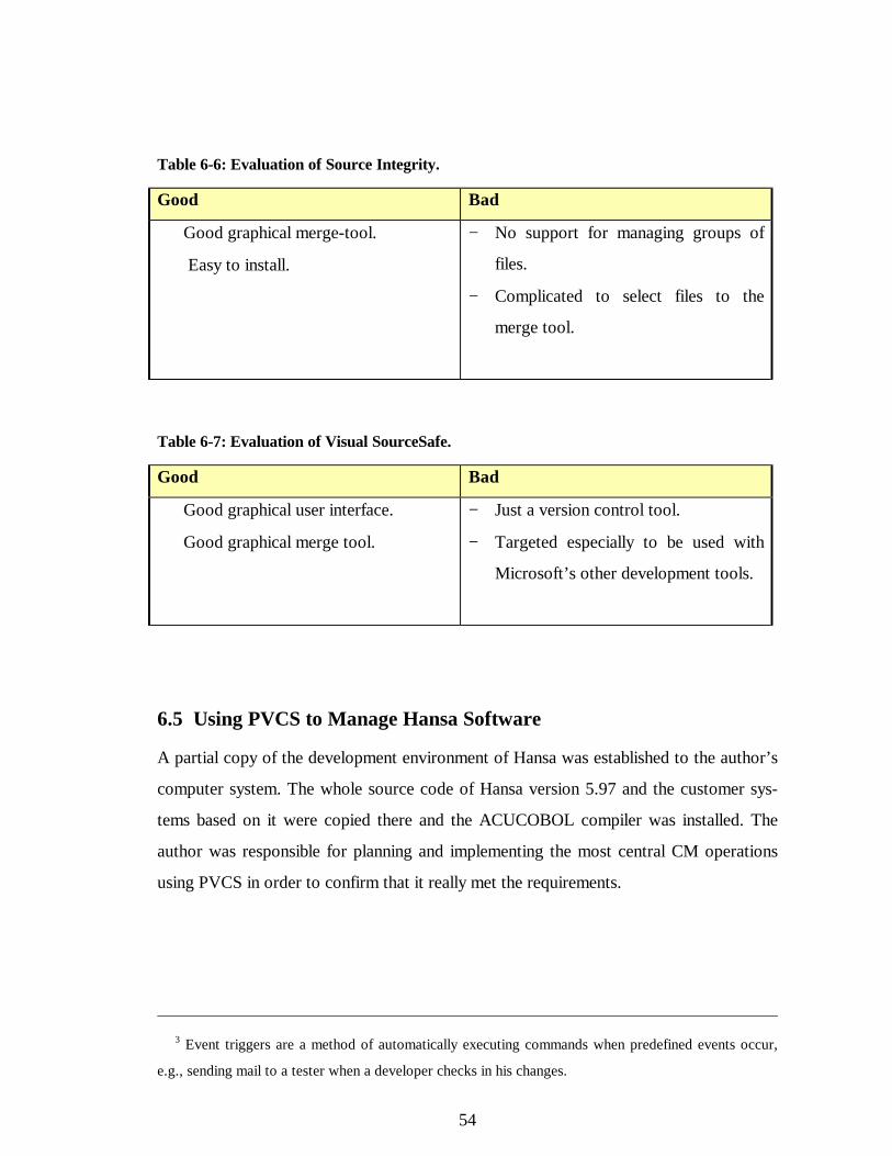
54
Table 6-6: Evaluation of Source Integrity.
Good Bad
+ Good graphical merge-tool.
+ Easy to install.
− No support for managing groups of
files.
− Complicated to select files to the
merge tool.
Table 6-7: Evaluation of Visual SourceSafe.
Good Bad
+ Good graphical user interface.
+ Good graphical merge tool.
− Just a version control tool.
− Targeted especially to be used with
Microsoft’s other development tools.
6.5 Using PVCS to Manage Hansa Software
A partial copy of the development environment of Hansa was established to the author’s
computer system. The whole source code of Hansa version 5.97 and the customer sys-
tems based on it were copied there and the ACUCOBOL compiler was installed. The
author was responsible for planning and implementing the most central CM operations
using PVCS in order to confirm that it really met the requirements.
3 Event triggers are a method of automatically executing commands when predefined events occur,
e.g., sending mail to a tester when a developer checks in his changes.
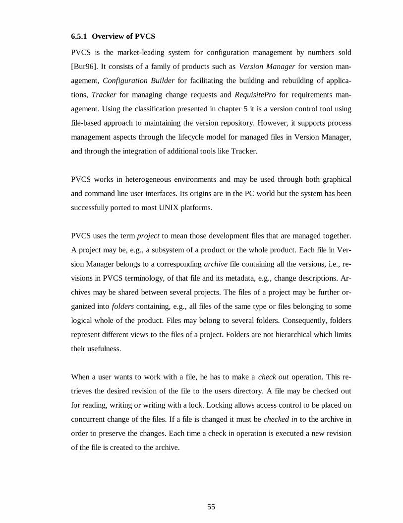
55
6.5.1 Overview of PVCS
PVCS is the market-leading system for configuration management by numbers sold
[Bur96]. It consists of a family of products such as Version Manager for version man-
agement, Configuration Builder for facilitating the building and rebuilding of applica-
tions, Tracker for managing change requests and RequisitePro for requirements man-
agement. Using the classification presented in chapter 5 it is a version control tool using
file-based approach to maintaining the version repository. However, it supports process
management aspects through the lifecycle model for managed files in Version Manager,
and through the integration of additional tools like Tracker.
PVCS works in heterogeneous environments and may be used through both graphical
and command line user interfaces. Its origins are in the PC world but the system has been
successfully ported to most UNIX platforms.
PVCS uses the term project to mean those development files that are managed together.
A project may be, e.g., a subsystem of a product or the whole product. Each file in Ver-
sion Manager belongs to a corresponding archive file containing all the versions, i.e., re-
visions in PVCS terminology, of that file and its metadata, e.g., change descriptions. Ar-
chives may be shared between several projects. The files of a project may be further or-
ganized into folders containing, e.g., all files of the same type or files belonging to some
logical whole of the product. Files may belong to several folders. Consequently, folders
represent different views to the files of a project. Folders are not hierarchical which limits
their usefulness.
When a user wants to work with a file, he has to make a check out operation. This re-
trieves the desired revision of the file to the users directory. A file may be checked out
for reading, writing or writing with a lock. Locking allows access control to be placed on
concurrent change of the files. If a file is changed it must be checked in to the archive in
order to preserve the changes. Each time a check in operation is executed a new revision
of the file is created to the archive.
56
If a file has variants, they are represented as branches in an archive. Differences between
two variants may be examined using a difference display tool. Changes to the branches
may be merged using a merge tool, which unfortunately does not have an interactive
conflict solving option.
Each revision of a file in an archive may be given a label. Labeling the revisions of the
files belonging to a specific version of the developed product may be used to retrieve the
product version in the future.
Each project may contain a promotion model representing the lifecycle states of man-
aged files. An example of a simple promotion model is development, test and release. A
new revision of a file belongs to the development state. Then it is promoted to testing. If
it passes the testing it is promoted to the release state, otherwise it is demoted back to
the development state.
Configuration Builder is a make like tool having some more advanced features. It may be
integrated with Version Manager, e.g., in order to make builds from the archives.
6.5.2 Implementation
Several projects were created to the PVCS, one for each major release of Hansa base
version and one for each customer version. The projects were named Hansa_X for the
base system and CustomerName_X for customer systems, X presenting the major version
number of the system. The files were organized into folders representing the directory
structure of the system, i.e., one folder for each directory. Customer projects contained
only those folders that included customized files and only the customized files were
placed in the folders. Additional folders must be created during the development to con-
tain the files belonging to a logical change. The project and folder structure was made in
a way to facilitate quick finding of the files operated as a group.
The central activities were planned, implemented, and their execution was documented in
a detailed guide. The purpose of the guide was to help the person, who would take the
responsibility to carry on the CM project in CompuPro. The activities were:
57
• Creating a project
• Creating a new customer system
• Taking an existing customer system into PVCS
• Making a change to the base system or to a customer system
• Merging the changes between the base system and customer systems
• Building the base system or a customer system
• Releasing a version of the base system or a customer system to a customer or for in-
ternal use
• Retrieving the source code of a specific release
• Using promotion model
6.6 Assessing the Proposed SCM System
The implementation of the proposal in CompuPro is still in pilot phase at the time of
writing of this thesis. However, some experiences from the pilot project are available al-
ready. The purpose of the pilot project is to implement the system described in the previ-
ous section in the premises of CompuPro and let the real users experiment with it and
refine the proposal before the final deployment. The pilot project is carried out by a per-
son who will be responsible for SCM issues in CompuPro and the author of this thesis
has been working as a consultant in the background.
The introduction of PVCS in CompuPro’s environment has not progressed without sev-
eral problems. Installing PVCS into a heterogeneous environment, where PVCS clients
are running on developers’ workstation and archives are on a UNIX server, required a
lot of experimenting to get the settings right. The overall usage of PVCS is not easy for a
new user and learning to be a PVCS administrator takes time. Acquiring deeper PVCS
training in the beginning of the pilot project might have shortened the learning curve. The
file sharing between the UNIX server and PC clients in the network appeared to be too
slow and unreliable for heavy use. The file sharing problems were solved by changing the
58
file sharing software from PC-NFS to Samba4. An unannounced limitation in PVCS has
also emerged. The GUI does not support more than 6500 files per project in some op-
erations and this limit had to be by-passed. Mainly due to the technical problems with
PVCS and the computer environment, the pilot project has already lasted three months.
The approach to introduce all the new processes at the same time appeared to be too
difficult. Changing a company’s development processes and release policy in a way that
would be required to fully deploy all new SCM processes is not realistic in a short time
scale. The major obstacles were the need for flexible and frequent releases, the lack of
resources for testing and technical problems with PVCS. Therefore, more advanced parts
of the proposal have been left out from the first implementation. The most significant
advantages, i.e., those pertaining to disciplined version control are still achieved. In addi-
tion, the new tool becomes familiar in the organization and new features may be intro-
duced as development and release processes are improved. The use of PVCS also col-
lects measurement data from the current development processes, e.g., number of changes
to a component, and the duration of making changes. This data can be used to improve
the development processes.
6.7 Conclusions of the SCM Improvement Project
Naturally, the author of this work and all parties involved have learned a lot about con-
figuration management and related issues. Therefore, when looking back, some issues
arise that we would do in another way if the project were started over.
In the beginning of the project, more focus should have been placed on the overall proc-
esses related to Hansa, especially to the release process. Now the focus was too much in
the development process. The improvement of the current frequent customer release
policy was almost neglected or at least it was thought that it could be improved in the
4 Samba is a suite of programs which work together to allow clients to access Unix filespace and
printers via the SMB (Session Message Block) protocol.
59
near future. During the pilot phase, a completely new project called LUCOS5, was
started to model, measure and improve the overall processes of Hansa development.
The choice to try to make all changes at the same time, in order to diminish the distur-
bances of introducing of new processes to one time, was unrealistic. An incremental ap-
proach would probably have been a better one to use already from the beginning of the
project. Now the change to an incremental approach was made only during the pilot
phase. The process improvement approach for software processes presented in the
CMM, where improvements are implemented gradually on a step by step basis, might be
used as a reference model for SCM process improvement, too.
Lack of commitment to the SCM project or in other words lack of time available to the
project of the key development personnel has also slowed down the progress of the pilot
project. The person responsible for the pilot project has had enough time for the work
but he is not an experienced Hansa developer. Therefore, lack of feedback from the new
SCM processes from the developers has caused delays and misunderstandings in refining
the processes. Naturally, technical problems with PVCS have delayed the building of the
SCM environment to such a form that it could have been released to be tested by the de-
velopers. The first impression from a new system must be positive in order to get the de-
velopers’ acceptance.
This work continues in parallel with the LUCOS project. Linking the improvement of
development, maintenance, release and other processes and new company policies with
the SCM processes is the challenge of the future work.
5 The LUCOS research project, carried out by the TAI Research Centre at Helsinki University of
Technology, aims to develop process modeling and measurement methods and metrics suitable for the
continuous improvement of product development processes in the electronics industry.
60
7 REFERENCES
[Art88] Arthur, L.J. Software Evolution: The software Maintenance Challenge.
John Wiley and Sons, US, 1988.
[Aue95] Auer, Antti and Taramaa, Jorma: Experience report on the maturity of
configuration management for embedded software. 6th International
Workshop on Software Configuration Management (SCM6), Berlin,
Germany, 1996.
[Ber92] Berlack, H. Ronald. Software Configuration Management. John Wiley
and Sons, Inc., New York, USA, 1992.
[Buc91] Buckley, Fletcher J. Implementing Configuration Management. IEEE
Press, 1992.
[Bur96] Burrows Clive et. al. Ovum Evaluates: Configuration Management.
Ovum Ltd., London, UK, 1996.
[Bro95] Brooks, Frederick P. Jr. The Mythical Man-Month: Essays on software
engineering. Addison-Wesley, Reading, Massachusetts, anniversary edi-
tion, 1995.
[Car95] Carmel Erran et. al. A Process Model for Packaged Software Develop-
ment. IEEE Transactions on Engineering Management, 42(1):50-61,
1995.
[Ced93] Cederqvist, Per. Version Management with CVS. Technical Report, Sig-
num Support AB, 1993.
[Cou89] Courington, W. The Network Software Environment. Technical Report
Sun FE197-0, Sun Microsystems Inc., 1989.
[Dar91] Dart, A. S. Concepts in Configuration Management Systems. In Pro-
ceedings of the 3rd International Workshop on Software Configuration
Management, pages 1-18, 1991.
61
[Dar92] Dart, A. S. The Past, Present, and Future of Configuration Management.
Technical Report CMU/SEI 92-TR-8, Software Engineering Institute,
Carnegie Mellon University, Pittsburgh, 1992.
[Dar95] Dart, A. S. Adopting An Automated Configuration Management Solu-
tion. Technical Report, Continuus Software Corporation, 1995.
[Fei91] Feiler, Peter H. Configuration Management Models in Commercial Envi-
ronments. Tech Rept. CMU/SEI-91-TR-7, ADA235782, Software Engi-
neering Institute, Carnegie Mellon University, 1991.
[Fel79] Feldman, Stuart I. Make-A program for maintaining computer programs.
Software--Practice and Experience, 9:255-265, 1979.
[Gul93] Gulla, Bjorn. The constraint diagram. An approach to visualizing the ver-
sion space. In Proc. 4th International Workshop on Software Configura-
tion Management, Baltimore, Maryland, USA, 1993.
[IEE90a] IEEE Std 610.12-1990, Standard Glossary of Software Engineering Ter-
minology. IEEE, New York, USA, 1990.
[IEE90b] IEEE Std 828-1990, Standard for Software Configuration Management
Plans. IEEE, New York, USA, 1990.
[Jas97] Jasthi, Shashi. Software Configuration Management Without Tears.
http://pw2.netcom.com/~sjasthi/scm.html, 1997.
[Pau93] Paulk, M.C. et al. Capability Maturity Model for Software, Version 1.1.
Tech Report CMU/SEI-93-TR-25, Software Engineering Institute, 1993.
[Rat97] Rational Software Corporation. http://www.rational.com/, 1997.
[Roc75] Rochkind, M.J. The source code control system. IEEE Trans. on soft-
ware engineering, SE-1 (4). 1975.
[Som95] Sommerville, Ian. Software Engineering. Addison-Wesley, US, 1995.
[Som96] Sommerville, Ian and Dean G. PCL: A language for modelling evolving
system architectures. BCS/IEE Software Engineering J, 1996.
[Sun97] Sun Microsystems Inc. JDK 1.1.5 Documentation.
http://www.javasoft.com/products/jdk/1.1/docs/index.html. US, 1997.

62
[Tic81] Tichy, Walter F. A data model for programming support environments. In
proceedings of the IFIP WG 8.1 Working Conference on Automated
Tools for Information System Design and Development, 1981.
[Tic85] Tichy, Walter F. RCS- a system for version control. Software Practice
and Experience, 15 (7). 1985.
[TRU97] TRUE Software. http://www.truesoft.com/, 1997.
[Whi91] Whitgift, David. Methods and tools for software configuration manage-
ment. John Wiley & Sons, Chichester, UK, 1991.
[Zel96] Zeller, Andreas. Configuration Management with Version Sets. Technisce
Universität Braunscweig, Germany, 1996.