improving road safety and efficiency using connected...
TRANSCRIPT

Department of Electrical Engineering
Improving Road Safety and Efficiency Using
Connected Vehicle Technology
Imran HayeeEE Department, University of Minnesota Duluth

Department of Electrical Engineering
What is DSRC?
Mission: Connected Vehicle Technology
Objectives: Safety, Mobility and Efficiency
2

Department of Electrical Engineering
Outline• Introduction
– DSRC Technology Overview
– Applications
– Work Zone Environment
• V2I Traffic Information System
• V2V Assisted V2I System
• VMS Integration
• V2V System – Ongoing Work
• Summary / Questions
3

Department of Electrical Engineering 4
DSRC Technology Overview
Dedicated Short Range Communication (DSRC) is also known as Connected Vehicle
Technology. It incorporates both Vehicle to Infrastructure (V2I) and Vehicle to
Vehicle (V2V) communication.
Technical Specifications:
• Range up to 1000 meters
• Data rate 6 to 27 mbps
• Vehicle speed up to 100MPH
Connected Vehicles Research Lab

Department of Electrical Engineering 5
Obstacles to Adoption of DSRC Technology
• The Chicken and Egg Dilemma
• Market Penetration
• Infrastructure Support

Department of Electrical Engineering
DSRC Potential Applications
• Traffic Information Systems
• Emergency Vehicle Signal Preemption
• Approaching emergency vehicle warning
• Weather and road conditions warning
• Curve speed warning
• Do not pass warnings
• Cooperative Adaptive Cruise Control
• Cooperative Forward Collision Warning
• Left Turn Assist
• Merge Assist
6

Department of Electrical Engineering 7
Work Zone Environment

Department of Electrical Engineering8
Total Work Zone Related Fatalities
Year
Work Zone
Related
Fatalities
2011 587
2010 576
2009 680
2008 720
2007 831
2006 1,004Source: Fatality Analysis Reporting System (FARS) - Final, NHTSA

Department of Electrical Engineering 9
Current Approach to Reduce Fatalities
Estimate travel time and communicate to the drivers

Department of Electrical Engineering
Outline
• Introduction– DSRC Technology Overview
– Applications
– Work Zone Environment
• V2I Traffic Information System
• V2V Assisted V2I System
• VMS Integration
• V2V System – Ongoing Work
• Summary / Questions
10

Department of Electrical Engineering 11
Stu
den
t In A
ction

Department of Electrical Engineering
Vehicle DetectionV2I System Architecture
• RSU is placed such that RSU monitoring range aligns with the end of the congestion.
• At periodic intervals, an OBU participation is requested by the RSU to monitor a vehicle’s
speed and position through a congestion area.
• RSU sends traffic alert message to all OBUs indicating travel time through monitoring area.
12

Department of Electrical Engineering 13
Field Demonstration
• The field demonstration site was chosen at Rice Lake Rd, Duluth MN with the
focus on providing a clear line of sight between RSU and the OBU.
• The RSU is placed near the congestion end due to reduced range on one side due to
signal blocking by back of the vehicle.
Start of RSU
Monitoring Range
End of RSU
Monitoring Range
End of Congestion: Known
Start of Congestion: Unknown
RSU

Department of Electrical Engineering
Outline
• Introduction– DSRC Technology Overview
– Applications
– Work Zone Environment
• V2I Traffic Information System
• V2V Assisted V2I System
• VMS Integration
• V2V System – Ongoing Work
• Summary / Questions
14

Department of Electrical Engineering
V2V-Assisted V2I System
DSRC RSU
Work Zone
Congestion length
V2I
Broadcast Coverage
Starting Location of Congestion
(Varying)Ending Location
of Congestion
15
Department of Electrical Engineering
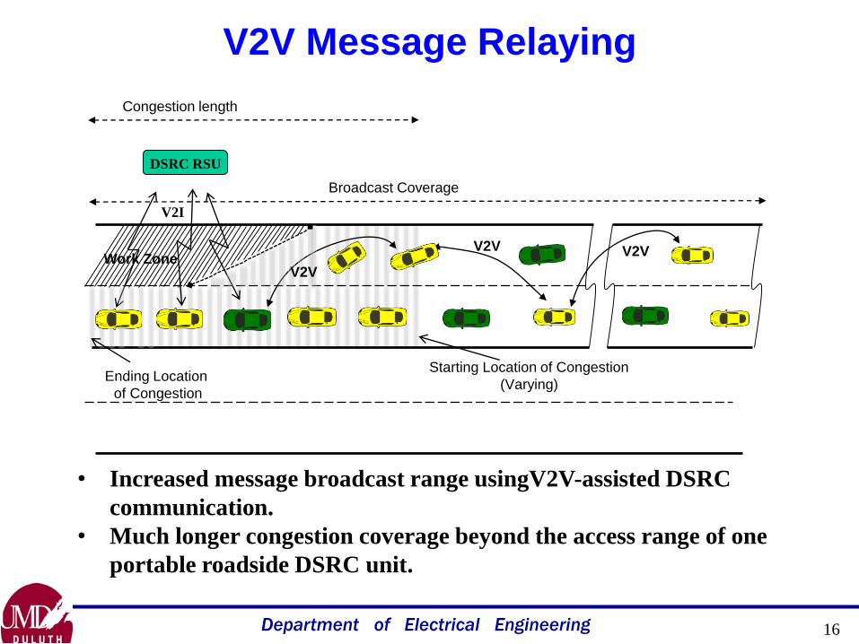
V2V Message Relaying
DSRC RSU
Work Zone
Congestion length
V2I
Broadcast Coverage
Starting Location of Congestion
(Varying)Ending Location
of Congestion
V2V V2V
V2V
• Increased message broadcast range usingV2V-assisted DSRC
communication.
• Much longer congestion coverage beyond the access range of one
portable roadside DSRC unit.
16

Department of Electrical Engineering 17
V2V Message Relaying
• Selective Relay
• Directive Relay
DSRC RSU
Work Zone
Congestion length
V2I
Broadcast Coverage
Starting Location of Congestion
(Varying)Ending Location
of Congestion
V2V V2V
V2V

Department of Electrical Engineering
Selective Relay
tb1
tb2
tb3
tb4
tb5
tb1
tb2
tb3
tb4
tb5tb5 < tb4 < tb3 < tb2 < tb1
• Only one of the vehicles should relay the message forward.
• Selection should be such that the number of hops can be minimized.

Department of Electrical Engineering
Directive Relay
Crossing Roads
Road with Work Zone
Reference Angle
Check
Message should be relayed towards the direction of the road
from which the vehicles are approaching towards the congestion.

Department of Electrical Engineering 20
Field Demonstration Setup - V2V
• The field demonstration site was chosen at Rice Lake Rd, Duluth MN with
the focus on providing a clear line of sight between RSU and the OBU.
• The RSU is placed nearer to the congestion end due to reduced range on
one side from the signal being blocked.

Department of Electrical Engineering
Outline
• Introduction– DSRC Technology Overview
– Applications
– Work Zone Environment
• V2I Traffic Information System
• V2V Assisted V2I System
• VMS Integration
• V2V System – Ongoing Work
• Summary / Questions
21

Department of Electrical Engineering22
DSRC Market Penetration
What Market Penetration is
needed for this system to
acquire Travel Parameters?
Not all vehicles will be DSRC equipped
in the initial deployment phase.

Department of Electrical Engineering23
Acquisition vs. Dissemination
Need for VMS Integration
DSRC Equipped VMS is
the answer but requires a
DSRC-VMS interface
How to communicate travel
parameters to the vehicles lacking
DSRC capability?
DSRC Equipped
VMS
CAUTION
WORK
ZONE
DSRC Equipped
VMS

Department of Electrical Engineering
Starting Location
of Congestion (Varying)
QUEUE
AHEAD
1.6 MI
DSRC-VMS Interface Demonstration
CAUTION
WORK
ZONE
DSRC Equipped
VMS
DSRC Equipped
VMS
24

Department of Electrical Engineering 25
Umair In Action

Department of Electrical Engineering
Outline
• Introduction– DSRC Technology Overview
– Applications
– Work Zone Environment
• V2I Traffic Information System
• V2V Assisted V2I System
• VMS Integration
• V2V System – Ongoing Work
• Summary / Questions
26

Department of Electrical Engineering 27
Current Work
V2IV2I
Work zone length ~ ½ Mile
V2I System
RSU
V2V
V2V
V2V
Work zone length ~ 3-5Miles
V2V Assisted V2I System
V2V
V2V
V2V
Work zone length ~ 3-5Miles
CAUTION
WORK
ZONE
V2V System
V2I

Department of Electrical Engineering
Summary
• Introduction– DSRC Technology Overview
– Applications
– Work Zone Environment
• V2I Traffic Information System– System Architecture and Design
– Field Demonstration
• V2V Assisted System– System Architecture and Design
– V2V Protocol
– Field Demonstration
• VMS Integration– Need
– Demonstration
• V2V System – Ongoing Work
• Summary / Questions
28