improving the performance of distance protection during ... · pdf file1 improving the...
TRANSCRIPT
1
Improving the Performance of Distance Protection during Wide Area Disturbances
Simon RICHARDS Damien THOLOMIER
AREVA T&D Automation - UK AREVA T&D Automation - Canada
INTRODUCTION
Distance relays have been successfully used for many years as the most common type of protection of transmission lines. The development of electromechanical and solid state relays with mho characteristics can be considered as an important factor in the wide spread acceptance of this type of protection at different voltage levels all over the world.
The implementation of distance relays requires understanding of the operating principles, as well as the factors that affect the performance of the device under different abnormal conditions. The undesired operation of numerous distance relays during the August 14 2003 North American blackout and the November 4 2006 European disturbance focuses the attention of protection engineers on the need for improvements in the application of these relays.
The setting of distance relays should ensure that they are not going to operate when not required (security) and will operate to trip when necessary (dependability).
The behavior of distance relays during several recent major blackouts combined with the significant pressure on utilities to increase the loading of their transmission systems are the reasons to look at dynamic loading of transmission lines and the effects that this has on the commonly used distance relays.
The application of Zone 3 as a backup protection function is being questioned by some engineers and was discussed in detail during last year’s conference [1]. The paper discussed in detail the requirements for backup protection, resistive reach coverage and dynamic load encroachment.
Many different characteristics of modern distance relays were analyzed in order to demonstrate that they can provide better protection and at the same time are not affected by the dynamic loading conditions that occur during wide area disturbances. This results in significant improvement of the performance of distance relays during wide area disturbances by preventing the operation of distance relays under dynamic load conditions. However, blocking the operation of the distance elements if a fault occurs at this time may result in a further degradation of the system conditions.
The paper discusses advanced methods for distance protection that detect load encroachment and out-of-step conditions, as well as unbalanced or balanced faults that may occur at the same time A new method for power swing detection based on superimposed components is also presented. It allows better detection, combined with correct operation of the relay when a fault occurs during the power swing.

2
DISTANCE PROTECTION OPERATION DURING THE AUGUST 2003 NORTH AMERICAN BLACKOUT AND NOVEMBER 2006 EUROPEAN DISTURBANCE
Distance Protection Operation During the North American Blackout The largest North American blackout occurred on 14 August, 2003, about 4:10 p.m. Eastern Daylight Time (EDT). It resulted in the loss of more than 70,000 megawatts (MW) of electrical load in parts of Ohio, Michigan, New York, Pennsylvania, New Jersey, Connecticut, Massachusetts, Vermont, and the Canadian provinces of Ontario and Quebec [1]. It is estimated that about 50 million people were affected [1].
The conclusions of the report were that as in previous blackouts a combination of many different factors resulted in the wide area system collapse. It was clear that the conditions in the system before the start of the sequence of events were not abnormal for the region for this time of the year.
The system conditions deteriorated and the disturbance spread beyond Ohio and caused a wide area blackout for three principal reasons [1]:
1. The loss of the 345 kV Sammis-Star line in Ohio, following the loss of other transmission lines and weak voltages within Ohio triggered many subsequent line trips.
2. Many of the key lines that tripped between 16:05:57 and 16:10:38 operated on Zone 3 impedance relays (or Zone 2 relays set to operate like Zone 3s), which responded to overloads rather than faults on the protected facilities. The speed at which they tripped accelerated the spread of the cascade beyond the Cleveland-Akron area.
3. The evidence indicates that the relay protection settings for the transmission lines, generators, and underfrequency load-shedding in the Northeast may not be sufficient to reduce the likelihood and consequences of a cascade, nor were they intended to do so.
The events in the cascade started slowly, but spread quickly. Figure 1 shows the relatively low number of lines and generators lost during the Ohio phase of the blackout. These numbers significantly increase after 16:08:59. The blackout was complete only 2.5 minutes later.
Fig. 1 Number of lines, transformers and generators tripped during the last phase of the blackout

3
Low voltage levels, combined with high load currents, and in some cases very high reactive flows resulted in the tripping of time delayed distance elements. The relay operated as designed and set. Figure 2 shows the apparent impedance inside Zone 3 of the distance protection on the 345 kV transmission line between Sammis and Star.
Fig. 2 Zone 3 distance relay operation on the 345 kV Sammis-Star transmission line
Distance relays did not trip only on Zone 3 due to the changes in the apparent impedance entering the characteristic. Relays on the lines between PJM and New York saw massive power swings caused by the swing of power out of Michigan toward Ontario and into New York and PJM. Zone 1 relays on the 345-kV lines didn't have power swing blocking available or enabled. As a result they tripped those lines and separated Pennsylvania from New York.
The final sequence of events list showed that the trip of the 345 kV Sammis-Star transmission line (at 16:06) was followed by the cascading failure of the electric power systems in parts of eight US states and two Canadian provinces. It included the trip of over 500 generating units and over 400 transmission lines and was completed in the next eight minutes. Most of the events actually occurred in the final 12 seconds of the cascade.
Distance Protection Operation During the European Disturbance
According to the final report on the November 4 European disturbance, it was the result of a sequence of events that started after a scheduled manual disconnection of the double-circuit 380 kV Conneforde-Diele line (E.ON Netz). The N-1 criterion used in UCTE was not fulfilled in the E.ON Netz grid and on some of its interconnections with the neighboring TSOs.
As a result of the switching, the power flow in some parts reached levels close to the established limits. The critical one was the 380 kV Landesbergen (E.ON Netz)-Wehrendorf (RWE TSO) line. As can be seen from Table 1 it was so close to the protection settings at the Wehrendorf substation (RWE TSO), that even a relatively small power flow deviation triggered the cascade of line tripping due to protection relay operation.

4
Table 1
This occurred as proper countermeasures to reduce the flow on this line were not undertaken, and instead only an empirical assessment was made that coupling of the busbars in the Landesbergen substation would just result in a reduction of the current by about 80 A. This switching was done at 22:10 without any load flow calculations for checking the N-1 criterion. However, the current instead increased (according to the simulations performed by the commission that analyzed the disturbance) by 67 A and the line was automatically tripped by the distance relays in the Wehrendorf substation due to overloading. Figure 3 shows the power flow before and after the switching.
Fig. 3 European disturbance November 4 2006
As a result of the Wehrendorf relay’s operation, dynamic loading and out-of-step conditions led to the tripping of another thirty 400, 380 and 220 kV lines within a period of about 1 second.
E.ON Netz (Landesbergen)
RWE TSO (Wehrendorf)
Steady state value (thermal capacity of the line)
2 000 A 2000 A
Warning value (alarm) 1000 A and 2 000 A 1 795 A (90% of the max. limit value)
Maximal accepted value 2 550 A (85% of tripping current) for max. 1 hour.
1995 A (95% of the tripping current
Tripping current 3 000 A 2 100 A

5
The European system was split in three parts with significant imbalances in two of them. About 17 GW of load shedding and 1.6 GW of pump shedding were necessary to restore the balance in the Western area.
IMPROVING THE PERFORMANCE OF DISTANCE RELAYS
From the analysis of the operation of distance relays during the North American and European blackouts it is clear that the operating time of the relay is not the only factor to be considered while selecting a distance protection for real-world transmission line applications (ie. exposed to dynamically-changing loadflows). The issues for both of the cases, and also other cases from history have been:
• Higher levels of dynamic load, compared to normal rated load. The higher loading may be due to loss of adjacent power corridors, and hence power rerouting via the remaining in-service line(s).
• Power swinging, where the dynamic readjustment of generator rotor angles and excitation to cater for the new topology produces an oscillatory effect.
• Out of step, (or pole-slipping for generators): whereby the power swing is so severe that the swing cannot stabilize, and the system or parts of it lose synchronism. In the case of long lines, those in-service are acting as a source of capacitive VARs, hence disconnection of such a line can add to the destabilizing effect, as the reactive power redistributes.
• Frequency excursions: where the generation/load balance is disturbed due to cases such as generator rejection, grid supply circuit tripping, or lack of load-shedding, the frequency may start to fall below the 60Hz nominal. In cases where faults have been cleared too slowly, and generator AVR circuits had tried to boost their output to compensate, there have even been cases of overfrequency upon fault clearance.
• Undervoltage, typically due to overloading, or insufficient meshing in a depleted network meaning that the voltage profile cannot be maintained.
• Overvoltage, which may again accompany an over-eager re-energisation/return to normality. Also, long lines which have been tripped at one end only can experience Ferranti-effect overvoltage at the open end.
• Other transients.
The distance elements of protective relays have to be selected and configured in such a way that they will provide sufficient resistive reach to ensure correct operation when a fault is inside of the designed zone of protection. The resistance of the arc has to be taken into consideration. It is affected my many factors, such as the distance between the phases and the extension of the arc by wind. This applies to phase and ground protection, with ground elements additionally needing to cater for vegetation and tower footing resistance. Figure 3 shows the protected transmission line in the impedance plane with the area of arc resistance that has to be covered by the protection element. Obviously, the characteristic needs to have a shape and be wide enough to provide this coverage.
6
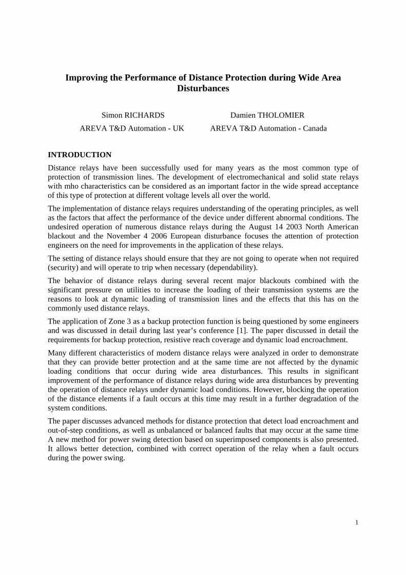
At the same time the characteristic should have a shape and settings that make it narrow enough so that the dynamically changing load impedance does not enter inside the characteristic – even if only for a few fleeting ms.
The effect of load on the operation of distance relays is well known and studied. It may lead to under or over-reaching of the distance characteristic. As seen during the blackout, the apparent impedance seen by the relays under very heavy loads may lead to relay tripping (Fig. 2). This is especially true in the case of long transmission lines or Zone 3 elements that have to provide backup protection for lines outgoing from substations with significant infeed. This is quite dangerous during wide area disturbances and will result in quick deterioration of the system and a blackout.
Fig. 4. Zone 2 with reverse offset Mho characteristic and load blinder and forward offset Zone 3 Mho characteristic
This analysis clearly demonstrates the problem with typical distance protection applications. Operation of distance relays with Mho characteristics under increased load conditions resulted in tripping of transmission lines and worsening of the overall system stability.
From Figure 4 above it is clear that the distance characteristics for each zone of a multifunctional transmission line protection relay should lie between the fault + arc impedance area and the load impedance area. The shaded part of the load impedance region corresponds to the normal and emergency rating of the line, while the white area is the load based on the dynamic rating.
The electromechanical or solid state relays with Mho characteristics have some problems with both these areas. They usually can not cover the arc impedance for faults at the end of the protected zone, while at the same time are subject to load encroachment, especially if the load is dynamically changing above the static rating of the transmission line.
Because of the significant problems with the application of Zone 3 distance elements with Mho characteristics, and especially after the blackouts in the 90's, some utilities have disabled them in
X
ZArc
ZLine
Zone 2
Zone 3
R
ZLoad

7
order to avoid potential line tripping during emergency system conditions. In other cases the reach settings are changed to reduce the probability for tripping under load conditions. However, this reduces the effectiveness of Zone 3 as a remote backup protection element, and the authors do not advocate the technical diligence of such an approach.
A little known fact is that with most mho characteristics constructed by phase comparators, that the borderline between a trip and no trip decision is a 90 degree angle. Hence, for relays which used a high degree of memory polarizing (such as a resonant voltage stored in an L-C circuit), if the frequency of the network deviated significantly from that of the memory, and for long enough to create a net 90 degree phase shift, a false trip could occur. Some mho characteristics would effectively rotate clockwise or counter clockwise, and in a worst case scenario of over 90 degree rotation the mho could then trip in a forward zone for a reverse fault (and vice versa).
All of the above has been taken into consideration in the design of modern microprocessor based (numerical) transmission line protection relays with distance characteristics.
If we would still like to have a Mho distance characteristic that provides sufficient arc resistance coverage but at the same time eliminates the possibility for tripping under maximum load conditions, we can select to use a transmission line protection relay that combines a Mho element with a load blinder. Modern relays with load encroachment functions should be considered during the selection of distance relays and while calculating the settings for each specific location. Different methods for load encroachment can be used – like the forward offset of the mho characteristic in Figure 4 or blinders and complex characteristics as shown in Figure 5.
More advanced load blinders can be designed using different elements, such as the ones shown in Figure 5. For example a blinder is formed from an underimpedance circle, with radius set by the user and two blinder lines crossing through the origin of the impedance plane. It cuts the area of the impedance characteristic that may result in operation under maximum dynamic load conditions, creating two stable segments around the areas of load infeed and outfeed.
The radius of the circle should be less than the maximum dynamic load impedance. The blinder angle should be set half way between the worst case power factor angle, and the line impedance angle.
Fig. 5. Zone 3 with advanced load blinder characteristics: circle + X-shape, or, left + right lines
8
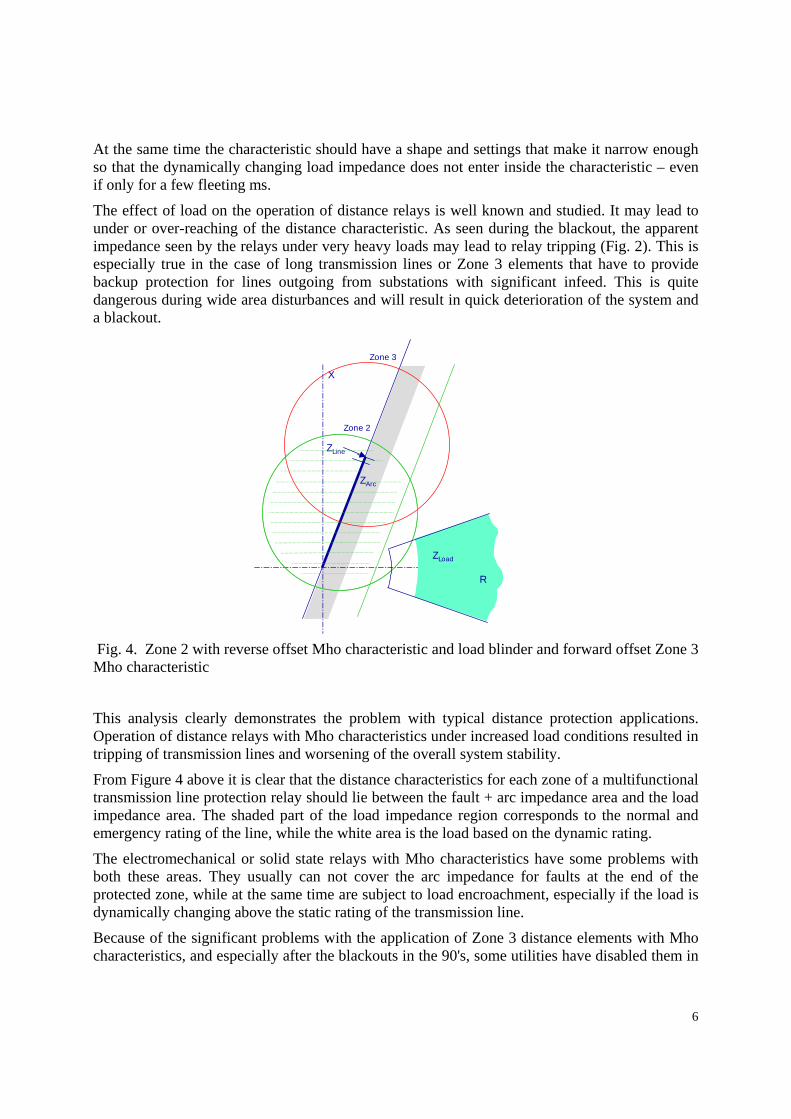
The combination of the distance zone (in the case of Figure 6 a Mho) and the load encroachment characteristic give the overall operating characteristic shown below.
Fig. 6. Distance characteristic with advanced load blinder characteristic
Such advanced operating characteristics are very important, because they prevent the operation of the distance relays in case of wide area disturbances like the ones described earlier in the paper.
The modern numerical relay under discussion will operate correctly because:
• The load blinder is not dependent on a memory voltage for construction, hence is not dynamically expanding or shifting, and so gives a fixed shape to defend against spurious trips.
• The frequency tracking, and hence the mho shape and directional decisions operate reliably – even during frequency excursions, power swinging etc. This means that there is no spurious risk of overtripping.
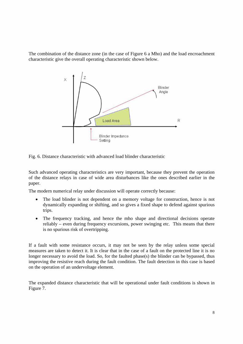
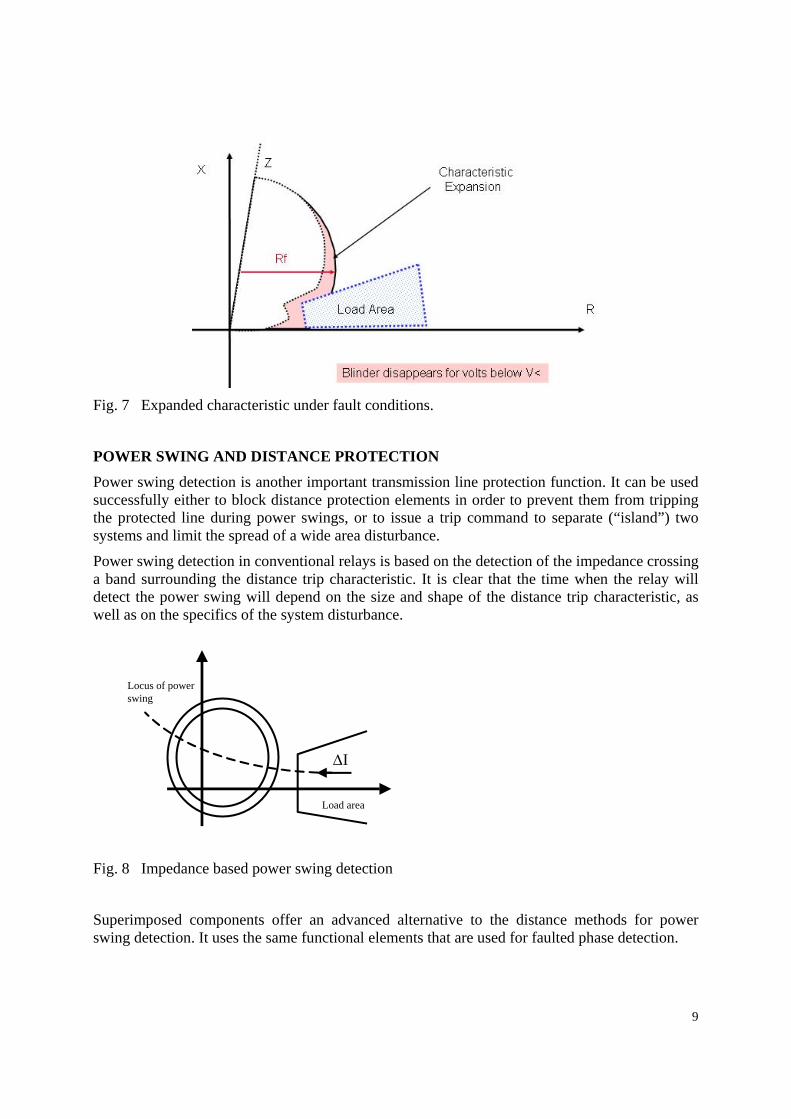
If a fault with some resistance occurs, it may not be seen by the relay unless some special measures are taken to detect it. It is clear that in the case of a fault on the protected line it is no longer necessary to avoid the load. So, for the faulted phase(s) the blinder can be bypassed, thus improving the resistive reach during the fault condition. The fault detection in this case is based on the operation of an undervoltage element.
The expanded distance characteristic that will be operational under fault conditions is shown in Figure 7.
9
Fig. 7 Expanded characteristic under fault conditions.
POWER SWING AND DISTANCE PROTECTION
Power swing detection is another important transmission line protection function. It can be used successfully either to block distance protection elements in order to prevent them from tripping the protected line during power swings, or to issue a trip command to separate (“island”) two systems and limit the spread of a wide area disturbance.
Power swing detection in conventional relays is based on the detection of the impedance crossing a band surrounding the distance trip characteristic. It is clear that the time when the relay will detect the power swing will depend on the size and shape of the distance trip characteristic, as well as on the specifics of the system disturbance.
Fig. 8 Impedance based power swing detection
Superimposed components offer an advanced alternative to the distance methods for power swing detection. It uses the same functional elements that are used for faulted phase detection.
Locus of powerswing
Load area
∆I

10
AB
BC
CA
Change!
Change!
NoChange!
1 CycleComparison
1 CycleComparison
Ground Fault,Phase C
Fig. 9 Superimposed components based faulted phase selection Since the superimposed components are directly related to the changes in system parameters caused by the fault, faulted phase selection can be based on superimposed quantities. One method is to use the superimposed components of the three phase-to-phase currents.
Figure 9 shows the changes in two of the phase-to-phase currents (IBC and ICA) for a phase C-G fault. This fault produces the same superimposed component in the BC and CA currents and zero in the AB current.
In the case of a phase-to-phase or two-phase-to-ground fault one of the phase-to-phase superimposed currents will be greater than the other two, while for a three-phase fault all three superimposed component magnitudes will be similar.
If the faulted phase selection is required to be maintained for times longer than the two-cycle memory buffer, the pre-fault samples from the buffer can be "recycled" and reused.
Fig. 10 Operation of superimposed component based faulted phase selectors Two phase selectors can be implemented for each phase-to-phase loop. The first (PH1) is the just described method comparing the last sample with one taken two cycles earlier. It will reset (see
PH1
PH2
Fault

11
Figure 10) after two cycles, because then it will be comparing two samples taken under fault conditions. The second (PH2) remains picked-up because it uses for the calculation of the superimposed components pre-fault data stored in the relay memory.
One of the big advantages of the superimposed component based faulted phase selection method is that it does not require any settings and is not significantly affected by the magnitude of the pre-fault load current. It also works very well under evolving fault conditions.
The power swing detection approach is based on the fact that a power swing will result in continuous change of current that will be seen as continuous output from the relay superimposed current elements PH1 and PH2 described earlier in the paper and shown in Figure 4.
This method offers some significant advantages, such as:
• It will detect all power swings whether fast or slow, and ensure correct blocking of zones.
• Detects, and remains stable for 3 and 2 phase swings - the latter is especially important for the resulting 2 phase swing during single pole autoreclose.
• Using this method the relay is able to operate for faults occurring during a power swing
Fig. 11 Superimposed components element operation during a power swing, and with a later fault inception
For a power swing condition there will be a continual output from PH1. While during a fault PH1 will remain picked-up for 2 cycles, during a power swing it will remain picked-up for the duration of the swing. If this state exceeds 2.5 cycles and no distance comparator has operated then the power swing detection can be activated. Several actions follow the operation of the power swing detector:
• All distance elements and zones selected by the user during the relay setting process are blocked
• A power swing blocking alarm will be issued if a distance element detects that the swing impedance subsequently enters a tripping zone
Powerswing
Fault
PH1
PH2
PSB active PSB removed
2.5 cycles
12
• The minimum threshold used by PH2 is increased to twice the maximum superimposed current prevailing during the swing. As a result, PH2 will reset at this moment (as seen in Figure 11.)
It is important to mention that depending on the location of the protective relay in the power system the detection of a power swing may also be used to issue a trip signal to separate two parts of the system.
The change of the threshold and subsequent reset of this phase selector element allows it to be used to detect a fault that occurs during the power swing.
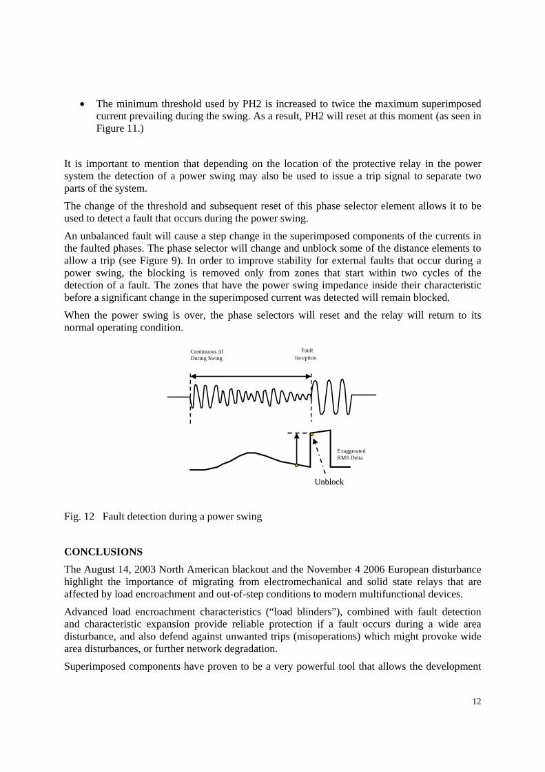
An unbalanced fault will cause a step change in the superimposed components of the currents in the faulted phases. The phase selector will change and unblock some of the distance elements to allow a trip (see Figure 9). In order to improve stability for external faults that occur during a power swing, the blocking is removed only from zones that start within two cycles of the detection of a fault. The zones that have the power swing impedance inside their characteristic before a significant change in the superimposed current was detected will remain blocked.
When the power swing is over, the phase selectors will reset and the relay will return to its normal operating condition.
Fig. 12 Fault detection during a power swing
CONCLUSIONS
The August 14, 2003 North American blackout and the November 4 2006 European disturbance highlight the importance of migrating from electromechanical and solid state relays that are affected by load encroachment and out-of-step conditions to modern multifunctional devices.
Advanced load encroachment characteristics (“load blinders”), combined with fault detection and characteristic expansion provide reliable protection if a fault occurs during a wide area disturbance, and also defend against unwanted trips (misoperations) which might provoke wide area disturbances, or further network degradation.
Superimposed components have proven to be a very powerful tool that allows the development
Continuous ∆IDuring Swing
FaultInception
ExaggeratedRMS Delta
UnblockUnblock
13
of advanced faulted phase selection, directional detection and power swing detection methods.
Superimposed component methods for power swing detection operate much earlier than impedance based methods. They also can be used to detect a fault during the out-of-step condition and clear it as necessary.
The use of two cycles of pre-fault samples and their further "recycling" allows the accurate calculation of the superimposed components for different periods of time after a fault inception.
The superimposed components based methods described in the paper are very efficient in the sense that they are very fast, while at the same time they do not require any configuration by the user.
Superimposed component based power swing detection is proven, and fast. It can be used to block protection elements from tripping, and at the same time can be used to separate two parts of a system affected by a wide area disturbance. This method also allows the detection and successful clearing of a fault that occurs during a power swing.
REFERENCES
1. Technical Analysis of the August 14, 2003, Blackout: What Happened, Why, and What Did We Learn? Report to the NERC Board of Trustees by the NERC Steering Group, North American Electric Reliability Council, July 13, 2004
2. UCTE, Final Report - System Disturbance on 4 November 2006, 30. 1.2007
3. MiCOMho P443 Technical Guide: P443/EN T, AREVA T&D Automation and Information Systems. www.areva-td.com/protectionrelays
4. Network Protection and Automation Guide, AREVA T&D, July 2002, ISBN: 2-9518589-0-6
AUTHORS
Simon Richards is the UK-based Marketing Director for Protection Products from AREVA, and leader of the transmission and railways segment. AREVA acquired the Transmission and Distribution businesses of ALSTOM. Protection Products are a part of AREVA’s Energy Automation and Information activity, and the author is based in Stafford, UK. He has a B.Eng (Hons) in Electrical and Electronic Engineering from the University of Bath, and is a Chartered Engineer, and MIEE. Previously a 25kV electrification Distribution Engineer
for the 500km West Coast Main Line railway between London and Scotland, Simon also held a number of protection applications engineering positions within ALSTOM prior to his current role. The Marketing function provides technical support to Sales and Service teams worldwide, and investigates opportunities for new product developments.

14
Damien Tholomier received a BEng in Electrical and Automation Engineering in 1992 from the University of Marseilles, France (Ecole Polytechnique Universitaire de Marseille). Damien joined ALSTOM T&D GmbH in Stuttgart, Germany where he worked for 5 years in the Protection & Control department as Power System Application Engineer. In 1997 Damien moved as Marketing Manager High Voltage Protection Business Unit with Alstom T&D Protection & Control in Lattes, France where he worked on full scheme distance protection algorithms. From 1999-2001 he was Sales & Service Director for Mediterranean
Countries and Africa. From 2002 he was Products Marketing Director for ALSTOM T&D then AREVA T&D Automation where he worked on new busbar relays (application of universal topology and CT saturation detection algorithms). Since 2006 he moved to Canada, leading the North American Automation team, and retaining the post of Marketing Innovation Director for Automation IEDs.