improving your deliverables with revit® structure and...
TRANSCRIPT

Improving Your Deliverables with
Revit® Structure and SDS/2 Connect Doug Evans Vice President – Sales, Design Data
@Doug_Evans_
Steve Vasquez Vice President / Principal
Chavez-Grieves Consulting Engineers

Model accuracy is vital to Building Information Modeling (BIM) projects,
and connections are a critical component of making the model
accurate. This class features real-world case studies from engineering
companies who have incorporated SDS/2 Connect into their Revit
Structure workflow. Highlights include how companies employ SDS/2
Connect as a way to keep the project schedule on track while providing
project owners with the ability to secure more competitive bids, use the
connection design functionality to avoid erection clashes during the
design phase of the project, and create a more valuable deliverable for
the owner and architect.
Class summary
At the end of this class, you will be able to:
Understand a real-life workflow for model transfers sent from engineers to
the manufacturers via the Revit Structure model
Learn how connection design can incorporate erection clash avoidance
into the design phase with your Revit Structure model
Gain knowledge from a real-life user; how using SDS/2 Connect has
improved their delivery process
Hear two case studies about the implementation process of SDS/2
Connect model round-tripping and connection design in Revit.
Key learning objectives
Introduction to SDS/2 Connect

Design Data
Software developer of SDS/2 Software solutions for 32 years
SDS/2 Detailing software
Connection design
Steel detailing
Steel fabricating
Steel erection
SDS/2 Connect
Connection Design
Revit Model Round-tripping with SDS/2 Detailing
Who We Are

Revit Structure Add-in
Implements SDS/2 connection design functionality within the
Revit Structure environment
Enables API-based transfer of design model from Revit Structure
to SDS/2 Detailing software used by fabricators/detailers
With or without connections
Can help fast track the steel detailing/fabrication process
SDS/2 Connect

Connection Design with SDS/2 Connect
Code based connection
design
US, Canadian, Australian
European code coming in
2015 version
Fit-up and
Constructability checks
Bolt clearances
Framing conditions

Connection Design with SDS/2 Connect
Automatic Connections
Loads
Connection adjustments
Constructability (no audio for this video)
User Connections

Model Transfer with SDS/2 Connect
Simple import or export
with the plug-in is FREE.
Round-tripping would
require purchase to
maximize benefits
Video (no audio for this video)

SDS/2 Connect Integrations
Integration with CSC
Fastrak to apply design
loads to connections
Video

SDS/2 Connect Integrations
Use RAM and RISA-3D
loads for connection
design
Options settings in SDS/2
Connect allow you to
choose how to read the
loads
Case Study One:
Oregon Military Depot

Military project
Pilot project for requiring LOD 400 deliverables
KPFF Consulting Engineers – Portland office
Engineer of Record
First project to submit LOD 400 Revit Structure model
Design-Bid-Build
LOD 400 requirements have been updated since this project
Software Used:
Revit Structure 2012
SDS/2 Connect 2012
Oregon Military Depot
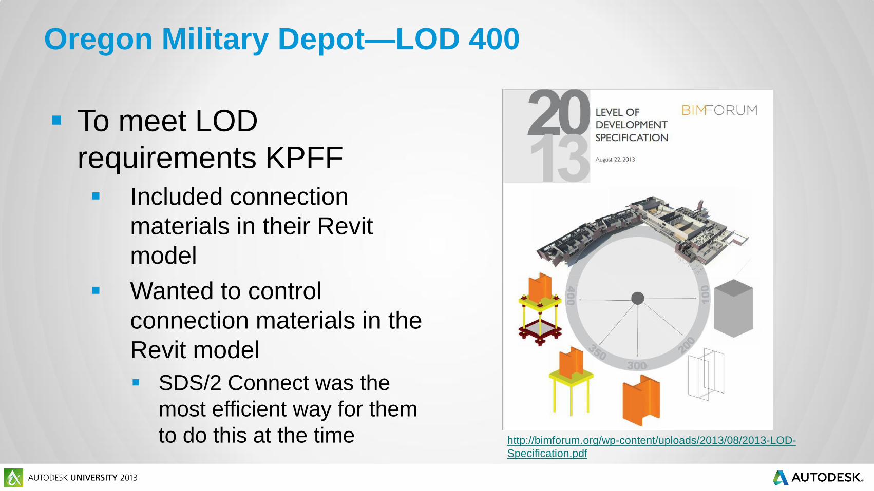
Oregon Military Depot—LOD 400
To meet LOD
requirements KPFF
Included connection
materials in their Revit
model
Wanted to control
connection materials in the
Revit model
SDS/2 Connect was the
most efficient way for them
to do this at the time http://bimforum.org/wp-content/uploads/2013/08/2013-LOD-
Specification.pdf

Using SDS/2 Connect, KPFF designers were able to
include within their Revit model:
Connection materials
Plates
Angles
Bolts
Connection design calculations
Connection sketches based on actual connections
Instead of “typical” situations
Oregon Military Depot—Connection Design

Oregon Military Depot—Connection Design
Connection material in
the model enabled
designers to see potential
field clashes
Designed connections to
prevent erection issues
Reduced the number RFIs
the detailer would have
had

LOD 400 Contract documents were completed using
Revit Structure
KPFF is aided in reaching LOD 400 in Revit by SDS/2 Connect
Completed LOD 400 CDs are delivered to
fabricator/detailer
Schuff Steel won the bid on this project
Oregon Military Depot—Design-Bid-Build

As a Design-Bid-Build project there was less
opportunity to influence the downstream use of SDS/2
which would have streamlined the detailing process
How?
SDS/2 Connect add-in only exports connections to SDS/2
Detailing
Schuff Steel does not use SDS/2 Detailing software and were not able
to take advantage of the connection design done by KPFF
Manual re-input would have been required to duplicate the
connections dictated by KPFF on this project
Oregon Military Depot—Design-Bid-Build

Ability to show designed connections in Revit
Accessibility of connection sketches
Automation of connection design calculations
Ability to see and avoid erection clashes during the
design phase
Designed with clash prevention in mind
Helped KPFF design a better structure
Oregon Military Depot—Benefits of SDS/2 Connect
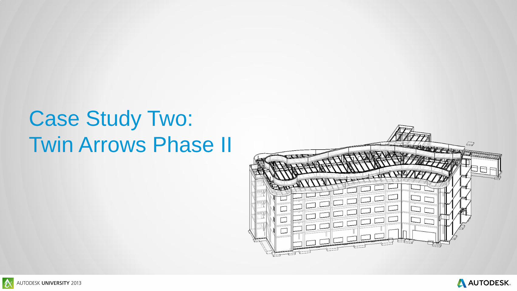
Case Study Two:
Twin Arrows Phase II

A Native-American gaming and hospitality project
Project funding came into question during design
Chavez-Grieves (C-G) detailed the project “at risk”
Kept project on schedule
Enabled Hunt Construction to get competitive bids
Didn’t have to commit to a fabricator before funding was settled
Twin Arrows-Phase II

General Contractor: Hunt Construction
Engineer: Chavez-Grieves Consulting Engineers
Detailer: Chavez-Grieves Consulting Engineers
Software Used:
Revit Structure 2012
SDS/2 Connect 2012
SDS/2 Detailing v 7.2
Twin Arrow-Phase II
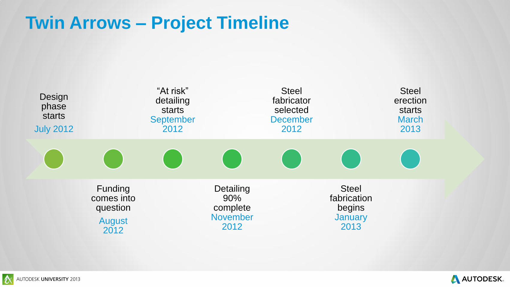
Design phase starts
July 2012
Funding comes into question
August 2012
“At risk” detailing
starts September
2012
Detailing 90%
complete November
2012
Steel fabricator selected
December 2012
Steel fabrication
begins January
2013
Steel erection
starts March 2013
Twin Arrows – Project Timeline

Project funding came into question while C-G was in
the design process
In order to keep the project going, C-G detailed the
project “at risk”
Developed detail drawings in parallel with design drawings
Marked advantage for time critical projects
C-G has both engineers and detailers in-house
Twin Arrows – Funding

September 2012
Design model completed and checked for accuracy in Revit
Transfer Revit Structure model to SDS/2 Detailing via SDS/2
Connect
Detailer begins with structural model
Saves 40 man-hours of input with the model transfer
Complicated geometry of roof input one-time in Revit
Reduced the number of RFIs that would have come from drawing set only
Connections designed and applied with SDS/2 Detailing
Miscellaneous steel input in SDS/2 Detailing
Twin Arrows – Detailing

Twin Arrows – Detailing
No official RFIs were
issued for the steel
RFI process remained in-
house as questions
between coworkers
Shaved an enormous
amount of time off the
detailing process

November 2012
Detailing was 90% complete
Hunt Construction started bid process for steel fabricator
Bids became more competitive
Based on Contract Documents and 90% shop drawings
Enabled Hunt Construction to get a better price for the owner
Normally steel detailing would just begin at this point.
Twin Arrows – Detailing
December 2012
Able Steel Fabricators of Mesa, AZ selected as fabricator
C-G incorporated Able Steel’s shop spec for last 10% of detailing
Naming conventions
i.e. piece marking
Sequencing
CNC considerations
Twin Arrows – Fabrication

January 2013
Able Steel can begin fabricating
3 months shaved off timeline by delivering shops with CDs
March 2013
Steel erection begins
Twin Arrows - Fabrication

Twin Arrows – Revit Model
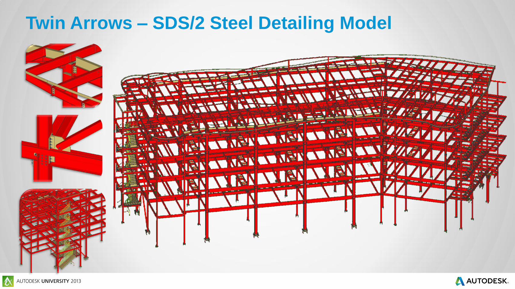
Twin Arrows – SDS/2 Steel Detailing Model

“At risk” detailing approached enabled C-G to keep
project alive
Model transfer saved time on input
Kept project schedule from slipping while searching out funding
Helped eliminate detailer’s RFIs by transferring an accurate Revit
model
Twin Arrows – Benefits of SDS/2 Connect
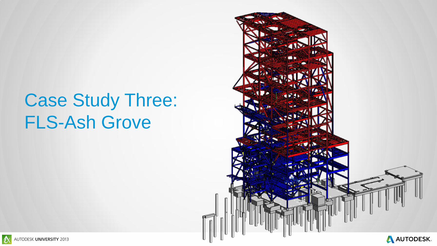
Case Study Three:
FLS-Ash Grove
Heavy Industrial Cement Manufacturing Plant
Pre-Heat Tower
Located in Midlothian, TX
3400 tons of steel
Steel structure is 250 ft tall
With all equipment, stands 340 ft
20 ft diameter duct work
C14x730 center column
Largest commercially rolled steel section in US
Still under construction
FLS-Ash Grove

Engineer:
Steel Detailer: Williams Steel
Fabricator: Williams Steel
Software Used:
Revit Structure 2013
SDS/2 Connect 2013
SDS/2 v. 7.3
FLS-Ash Grove

Model input in
Revit Structure
Transferred to SDS/2 Detailing via SDS/2
Connect
Connection Design in Revit Structure
(Vertical brace, moment & Splice connections)
Revit model with connections shared for
clash prevention
Design calcs submitted with CD package
Connection Design in SDS/2 Detailing
(Vertical brace, moment & Splice connections)
Connection Design completed in SDS/2
Detailing
Shop Drawings & CNC created for steel
fabrication
FLS-Ash Grove – Project work process

Designer input 100% of the structural steel in the Revit
model
Accuracy counts!
Important for set up to match in SDS/2 Connect and SDS/2
Detailing
SDS/2 Connect XML file from Revit model populated
the detailer’s model in SDS/2 Detailing
Speedier than IFC
Contains more detailed steel information
FLS-Ash Grove – Model Transfer

Connection Design was done in tandem
Engineer & detailer input connections simultaneously in Revit and
SDS/2 Detailing
Connection design focus:
Large vertical brace connections
Gussets averaged 6’x4’
Large column splices
Splices design for W14x730s to W14x665s
Moment connections
FLS-Ash Grove – Connection Design

After this point the engineer’s model (Revit) and
detailer’s model (SDS/2) have two different purposes
Revit model
Clash prevention with other disciplines
Contract Docs
SDS/2 model
Complete connection design
Shop drawings
CNC
FLS-Ash Grove – Connection Design

FLS-Ash Grove – Connection Design (Revit)
Revit model with vertical
braces connections is
shared with design team
Used to avoid interferences
during design for:
Pipes
Cable trays
Large equipment

Contract Documents are prepared for delivery
Connection design calculations for early designed connections
are printed from SDS/2 Connect
Sections from Revit model are created to show connection
sketches to GC and owner
FLS-Ash Grove – Model Usage (Revit)
SDS/2 Detailing model is used to complete connection
design on the structure
Girders
In-fill beams, etc.
Miscellaneous steel added to the model and connected
Handrail
Ladders
Supports
FLS-Ash Grove – Connection Design (SDS/2)
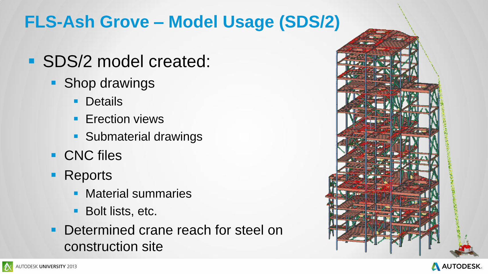
SDS/2 model created:
Shop drawings
Details
Erection views
Submaterial drawings
CNC files
Reports
Material summaries
Bolt lists, etc.
Determined crane reach for steel on
construction site
FLS-Ash Grove – Model Usage (SDS/2)

FLS-Ash Grove – Revit Model
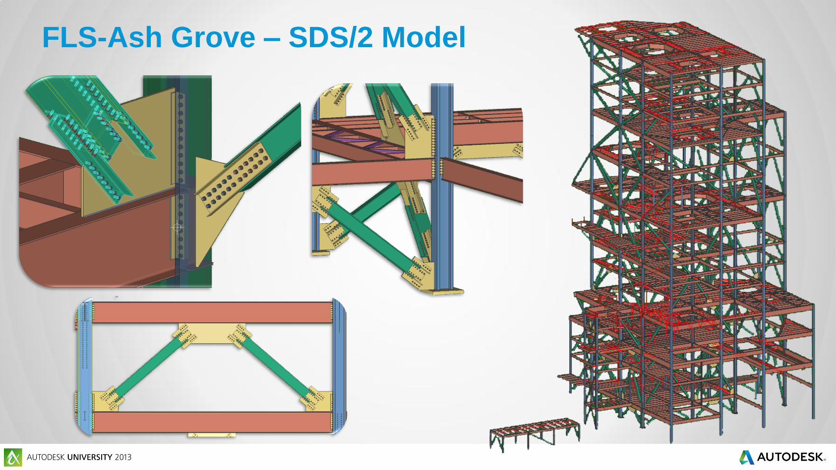
FLS-Ash Grove – SDS/2 Model

Ability to have critical connections in the Revit model
that could be shared for:
Clash prevention in tight spaces for mechanical design
Live sections for GC and owner
Design calculations that were submitted with CDs
FLS-Ash Grove – Benefits of SDS/2 Connect
SDS/2 Connect
Doug Evans
Vice President - Sales
Design Data
1501 Old Cheney Road
Lincoln, NE 68512
www.sds2.com
@Doug_Evans_
402-441-4000 x 102
Steve Vasquez
Vice President/Principal
Chavez-Grieves Consulting
Engineers, Inc.
4700 Lincoln Road NE
Albuquerque, NM
www.cg-engrs.com
505-344-4080

Autodesk is a registered trademark of Autodesk, Inc., and/or its subsidiaries and/or affiliates in the USA and/or other countries. All other brand names, product names, or trademarks belong to their respective holders. Autodesk reserves the right to alter product and services offerings, and specifications and pricing at any time without notice, and is not responsible for typographical or graphical errors that may appear
in this document. © 2013 Autodesk, Inc. All rights reserved.