imr specification document - dynist-maestro.dyndns.org/maestro/pages/publication/ftp/...ist...
TRANSCRIPT

IST Integrated Project No 507023 – MAESTRO
D6-4.1
IMR Specification Document Contractual Date of Delivery to the CEC: 30/06/2004
Actual Date of Delivery to the CEC: 30/07/2004
Author(s): Holger HERBRIG
Participant(s): see table Document Authors
Workpackage: WP06
Est. person months: 6.5
Security: Pub.
Nature: R (Report)
CEC release: 1.0
Version: 3.0
Total number of pages: 80
Abstract:
This documents contains the intermediate module repeater (IMR) specification. It will determine all requirements applying to the IMR for the SDMB commercial sys-tem.
Keyword list: SDMB IMR repeater specification
D6-4.1 MAESTRO: An IST Integrated Project No. 507023
30/07/2004 D6-4.1_V3.0 Page 2 D6-4.1_ASEL_MAESTRO_V3.0
EXECUTIVE SUMMARY This is the 4th of 8 tasks in Work Package 6 – ”Architecture". The WP aims at the identification and definition of the technical requirements for the SDMB-system. It determines the SDMB architecture which is to inter-work with the 3GPP-architecture and all relevant system requirements.
Under this WP functions and interfaces of the SDMB and all sub-systems will be defined, in particular the user equipment, intermediate module repeaters (IMR), space segment, hub and service centre. After the establishment of alternative sys-tem concepts a number of cost considerations will be made aiming at impact in-vestigations of SDMB features like 3G handset, BM_SC, manufacturing and instal-lation cost in particular for the IMR and the hub. Finally investigations into the im-pact of the SDMB on the 3GPP mobile network will be drawn up.
The IMR specification generating task (Task 6.4, matter of this document) will de-termine all requirements applying to the SDMB intermediate module repeater (IMR) and evaluate the technical and economical implementations of the IMR functions and performance ensuring and taking into account, too, potential co-siting of the IMR with 3G base stations and other equipment.
This task will deliver specifications for the hardware and software architecture of an IMR and its interfaces with respect to necessary modifications of existing equipment and modules. In addition this task will investigate new equipment to cope with synchronisation and uni-directional Iub-issues and/or optional Iur issues.
Under this task the IMR interfaces for both internal and to the outside world will be determined and described including the required functions and performance,
Furthermore, Task 6.4 will specify the IMR software taking into account, if neces-sary, synchronisation and O&M requirements.
Finally, the final document will evaluate the IMR cost for both recurring and non recurring costs, including deployment.
As outcome this task will produce engineering results allowing to choose between different types of IMR (cost linked to IMR itself but also to satellite/hub supplemen-tary features to implement). It should also provide some prices regarding RF power, that will be used to choose between many low power IMR Vs a few high power ones.
A special attention should also be paid to the possibility of co-existence of different IMR types in the project, and their possible succession in time if relevant.
This paper contains of 7 chapters, where chapters 1 to 3 deal with the introduction, references, terms and definitions. Chapter 4 gives a view on SDMB system fea-tures and requirements relevant for the IMR specifications which will be executed in the subsequent chapter 5. Chapter 6 contains a collection of specifically investi-

D6-4.1 MAESTRO: An IST Integrated Project No. 507023
30/07/2004 D6-4.1_V3.0 Page 3 D6-4.1_ASEL_MAESTRO_V3.0
gated technical items and issues while chapter 7 is intended to list all specification tables.
Figure 3: Deliverable D06-4.1 document tree depicts a graphical view on the document.
This document will be updated during the Maestro project.
D6-4.1 MAESTRO: An IST Integrated Project No. 507023
30/07/2004 D6-4.1_V3.0 Page 4 D6-4.1_ASEL_MAESTRO_V3.0
COPYRIGHT © Copyright 2004 The MAESTRO Consortium consisting of :
Alcatel Space (ASP), France Motorola Semiconducteurs SAS (MSPS), France LogicaCMG UK Limited (LOGICACMG), United Kingdom Agilent Technologies Belgium SA (AGILENT), Belgium Ascom Systec AG (ASC), Swiss University College London (UCL), United Kingdom Alma Mater Studiorum University Of Bologna (UOB), Italy The University of Surrey (UNIS), United Kingdom Fraunhofer Gesellschaft e.V. (FHG/IIS), Germany Udcast (UDCAST), France Space Hellas SA (SPH), Greece Ercom Engineering Reseaux Communications (ERCOM), France AWE Communications GMBH (AWE), Germany GFI Consulting (GFIC), France SES Astra (SES), Luxembourg British Telecommunications PLC (BT), United Kingdom E-TF1 (E-TF1), France Bouygues Telecom (BYTL), France Alcatel CIT (A-CIT), France Alcatel SEL AG (ASEL), Germany
This document may not be copied, reproduced, or modified in whole or in part for any purpose without written permission from the MAESTRO Consortium. In addi-tion to such written permission to copy, reproduce, or modify this document in whole or part, an acknowledgement of the authors of the document and all appli-cable portions of the copyright notice must be clearly referenced.
All rights reserved.
This document may change without notice.

D6-4.1 MAESTRO: An IST Integrated Project No. 507023
30/07/2004 D6-4.1_V3.0 Page 5 D6-4.1_ASEL_MAESTRO_V3.0
DOCUMENT HISTORY Vers. Issue Date Content and changes 0.1 31st of May 2004 Document initial draft for R1
0.3 06th of July 2004 Document for circulation
3.0 30th of July 2004 Document for submission as draft
D6-4.1 MAESTRO: An IST Integrated Project No. 507023
30/07/2004 D6-4.1_V3.0 Page 6 D6-4.1_ASEL_MAESTRO_V3.0
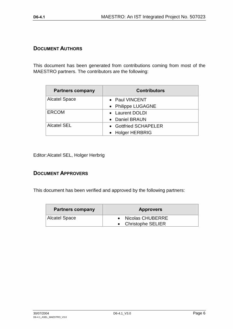
DOCUMENT AUTHORS
This document has been generated from contributions coming from most of the MAESTRO partners. The contributors are the following:
Partners company Contributors
Alcatel Space Paul VINCENT Philippe LUGAGNE
ERCOM Laurent DOLDI Daniel BRAUN
Alcatel SEL Gottfried SCHAPELER Holger HERBRIG
Editor: Alcatel SEL, Holger Herbrig
DOCUMENT APPROVERS
This document has been verified and approved by the following partners:
Partners company Approvers
Alcatel Space Nicolas CHUBERRE Christophe SELIER
D6-4.1 MAESTRO: An IST Integrated Project No. 507023
30/07/2004 D6-4.1_V3.0 Page 7 D6-4.1_ASEL_MAESTRO_V3.0
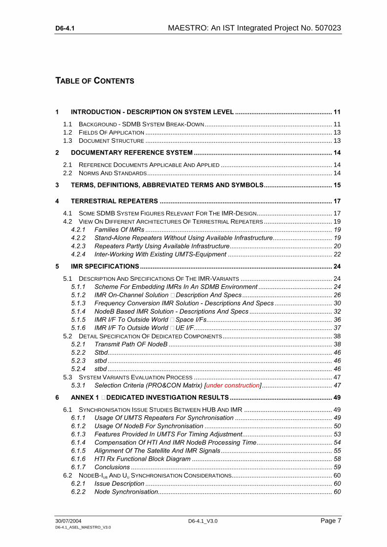
TABLE OF CONTENTS
1 INTRODUCTION - DESCRIPTION ON SYSTEM LEVEL ...................................................... 11
1.1 BACKGROUND - SDMB SYSTEM BREAK-DOWN....................................................................... 11 1.2 FIELDS OF APPLICATION ........................................................................................................ 13 1.3 DOCUMENT STRUCTURE ........................................................................................................ 13
2 DOCUMENTARY REFERENCE SYSTEM ............................................................................. 14
2.1 REFERENCE DOCUMENTS APPLICABLE AND APPLIED .............................................................. 14 2.2 NORMS AND STANDARDS....................................................................................................... 14
3 TERMS, DEFINITIONS, ABBREVIATED TERMS AND SYMBOLS...................................... 15
4 TERRESTRIAL REPEATERS ................................................................................................ 17
4.1 SOME SDMB SYSTEM FIGURES RELEVANT FOR THE IMR-DESIGN.......................................... 17 4.2 VIEW ON DIFFERENT ARCHITECTURES OF TERRESTRIAL REPEATERS ...................................... 19
4.2.1 Families Of IMRs ........................................................................................................ 19 4.2.2 Stand-Alone Repeaters Without Using Available Infrastructure................................. 19 4.2.3 Repeaters Partly Using Available Infrastructure......................................................... 20 4.2.4 Inter-Working With Existing UMTS-Equipment .......................................................... 22
5 IMR SPECIFICATIONS........................................................................................................... 24
5.1 DESCRIPTION AND SPECIFICATIONS OF THE IMR-VARIANTS ................................................... 24 5.1.1 Scheme For Embedding IMRs In An SDMB Environment ......................................... 24 5.1.2 IMR On-Channel Solution – Description And Specs .................................................. 26 5.1.3 Frequency Conversion IMR Solution - Descriptions And Specs ................................ 30 5.1.4 NodeB Based IMR Solution - Descriptions And Specs .............................................. 32 5.1.5 IMR I/F To Outside World – Space I/Fs...................................................................... 36 5.1.6 IMR I/F To Outside World – UE I/F............................................................................. 37
5.2 DETAIL SPECIFICATION OF DEDICATED COMPONENTS ............................................................. 38 5.2.1 Transmit Path OF NodeB ........................................................................................... 38 5.2.2 Stbd............................................................................................................................. 46 5.2.3 stbd ............................................................................................................................. 46 5.2.4 stbd ............................................................................................................................. 46
5.3 SYSTEM VARIANTS EVALUATION PROCESS ............................................................................. 47 5.3.1 Selection Criteria (PRO&CON Matrix) [under construction] ....................................... 47
6 ANNEX 1 – DEDICATED INVESTIGATION RESULTS ......................................................... 49
6.1 SYNCHRONISATION ISSUE STUDIES BETWEEN HUB AND IMR ................................................. 49 6.1.1 Usage Of UMTS Repeaters For Synchronisation ...................................................... 49 6.1.2 Usage Of NodeB For Synchronisation ....................................................................... 50 6.1.3 Features Provided In UMTS For Timing Adjustment.................................................. 53 6.1.4 Compensation Of HTI And IMR NodeB Processing Time.......................................... 54 6.1.5 Alignment Of The Satellite And IMR Signals .............................................................. 55 6.1.6 HTI Rx Functional Block Diagram .............................................................................. 58 6.1.7 Conclusions ................................................................................................................ 59
6.2 NODEB-IUB AND UU SYNCHRONISATION CONSIDERATIONS........................................................ 60 6.2.1 Issue Description ........................................................................................................ 60 6.2.2 Node Synchronisation................................................................................................. 60
D6-4.1 MAESTRO: An IST Integrated Project No. 507023
30/07/2004 D6-4.1_V3.0 Page 8 D6-4.1_ASEL_MAESTRO_V3.0
6.2.3 Network Synchronisation............................................................................................ 61 6.2.4 Down-Link Transport Channel Synchronisation ......................................................... 61 6.2.5 Down-Link Timing Adjustment.................................................................................... 62 6.2.6 MAESTRO Synchronisation Requirements................................................................ 62 6.2.7 Radio Interface Synchronisation (Uu) ......................................................................... 63 6.2.8 Conclusions: ............................................................................................................... 63
6.3 STANDARD SYNCHRONISATION PROCEDURES IN DETAIL.......................................................... 64 6.3.1 Parameters And Functionality .................................................................................... 64 6.3.2 Using NodeB - RNC Synchronisation......................................................................... 65 6.3.3 Conclusions ................................................................................................................ 66
6.4 SYNCHRONISATION BASED ON GPS....................................................................................... 67 6.4.1 GPS Application On The SDMB Core System ........................................................... 67 6.4.2 GPS Receiver Connection To The NodeB ................................................................. 67 6.4.3 The GPS Receiver Components ................................................................................ 67 6.4.4 GPS-Clock Based Synchronisation Procedure .......................................................... 68 6.4.5 Identified State Of Realisation .................................................................................... 69 6.4.6 Identified Problems For The GPS Synchronisation.................................................... 69 6.4.7 Required SW Implementations................................................................................... 70 6.4.8 Conclusions ................................................................................................................ 70
6.5 SHARED NODEB PHYSICAL ISSUES......................................................................................... 71 6.5.1 General Considerations.............................................................................................. 71 6.5.2 Shared NodeB RF Analogue Front End ..................................................................... 71 6.5.3 Shared Iub-Interface .................................................................................................... 76 6.5.4 Shared Iur Interface ..................................................................................................... 78 6.5.5 Conclusions ................................................................................................................ 79
7 ANNEX 2 - SPECIFICATION TABLES................................................................................... 80
D6-4.1 MAESTRO: An IST Integrated Project No. 507023
30/07/2004 D6-4.1_V3.0 Page 9 D6-4.1_ASEL_MAESTRO_V3.0
LIST OF TABLES
Table 1: NodeB power budget ............................................................................ 40
Table 2: Tx frequency error budget..................................................................... 41
Table 3: Spectrum emission mask values for different output power ................... 42
Table 4: Adjacent channel leakage ratio at TX and platform output..................... 43
Table 5: Error vector magnitude (EVM) requirements......................................... 45
Table 6: Peak code domain error (PCDE) requirements...................................... 45
Table 7: Uu - UMTS radio interface functionality.................................................. 72
Table 8: Iub interface functionality........................................................................ 76
LIST OF FIGURES
Figure 1: SDMB Architecture................................................................................. 11
Figure 2: Underlying architecture for IMR-specification......................................... 13
Figure 3: Deliverable D06-4.1 document tree........................................................ 13
Figure 4: Three IMR-principle architecture types .................................................. 19
Figure 5: NodeB IMR functional architecture ........................................................ 21
Figure 6: IMR architecture scheme for Uu-repeater............................................... 21
Figure 7: IMR architecture scheme for Iub-repeater............................................... 21
Figure 8: HTI Rx inserted on Iub............................................................................. 22
Figure 9: HTI Rx not inserted on Iub....................................................................... 22
Figure 10: RNC based IMR ................................................................................. 23
Figure 11: The Basic System – IMR Embedding................................................. 24
Figure 12: Basic system mapped on SDMB IMR architecture ............................. 25
Figure 13: IMR – On-channel based repeater branch ......................................... 26
Figure 14: IMR – frequency conversion based repeater branch.......................... 30
Figure 15: IMR - NodeB based repeater branch.................................................. 32
Figure 16: Spectrum emission mask at reference point....................................... 42
D6-4.1 MAESTRO: An IST Integrated Project No. 507023
30/07/2004 D6-4.1_V3.0 Page 10 D6-4.1_ASEL_MAESTRO_V3.0
Figure 17: RNC-NodeB synchronisation.............................................................. 52
Figure 18: TOA monitoring .................................................................................. 53
Figure 19: Channels used in SDMB .................................................................... 53
Figure 20: Timing of P-CCPCH and S-CCPCH .................................................. 54
Figure 21: Direct link and IMR link....................................................................... 55
Figure 22: Distances through direct link and IMR link.......................................... 56
Figure 23: Propagation delay variants ................................................................. 57
Figure 24: HTI Rx functional block diagram......................................................... 59
Figure 25: Down-link physical channels - radio frame timing and access slot timing 62
Figure 26: FDD Radio interface synchronisation timing diagram......................... 64
Figure 27: NodeB´s radio front-end ..................................................................... 72
Figure 28: MAESTRO add-on (1) for NodeB sharing .......................................... 73
Figure 29: MAESTRO add-on (2) for NodeB sharing .......................................... 74
Figure 30: Wide-Band distribution system (WDS) ............................................... 76
Figure 31: Addendums for Iub-sharing.................................................................. 77
Figure 32: Addendums for Iur-sharing .................................................................. 78

D6-4.1 MAESTRO: An IST Integrated Project No. 507023
30/07/2004 D6-4.1_V3.0 Page 11 D6-4.1_ASEL_MAESTRO_V3.0
1 INTRODUCTION - DESCRIPTION ON SYSTEM LEVEL
1.1 Background - SDMB System Break-Down
Figure 1 [Mae0] gives a rough view on the operational context where the SDMB core system is embedded in. A brief description may help both to get a view on the whole SDMB system as well as identify finally the later working area environment of this deliverable D6-4.1.
Starting on right hand side a content provider exemplifies a data source whose data content is forwarded to the ground station (BM_SC) and subsequently fed into a satellite (SPACE) via the functional block accommodating the Iub-generation and the transmission equipment (amplifiers, antennas, etc.). Both blocks together form the hub.
User UE IMR Tx-equip.
BM_ SC
Contentprovider
SPACE
3G
2G
SDMB - Infrastructure
Operat ional Context
Operat ional System
Core System
SDMB System
HUB
Figure 1: SDMB Architecture
The SPACE satellite beats down the received data, whereas the whole operational system to be covered by the satellite can be regarded (as an example reflecting the approximate dimensions) as at least nation wide. Transmission from satellite to the user equipment (UE) may occur principally across two different branches:
direct broadcast from satellite to the UE;
D6-4.1 MAESTRO: An IST Integrated Project No. 507023
30/07/2004 D6-4.1_V3.0 Page 12 D6-4.1_ASEL_MAESTRO_V3.0
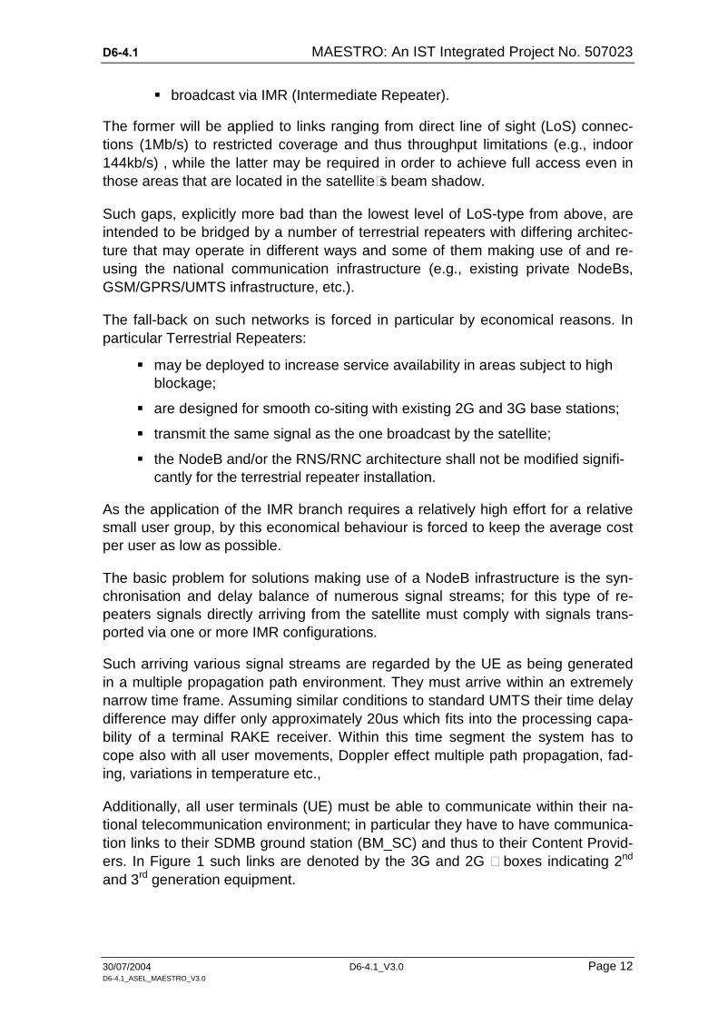
broadcast via IMR (Intermediate Repeater).
The former will be applied to links ranging from direct line of sight (LoS) connec-tions (1Mb/s) to restricted coverage and thus throughput limitations (e.g., indoor 144kb/s) , while the latter may be required in order to achieve full access even in those areas that are located in the satellite´s beam shadow.
Such gaps, explicitly more bad than the lowest level of LoS-type from above, are intended to be bridged by a number of terrestrial repeaters with differing architec-ture that may operate in different ways and some of them making use of and re-using the national communication infrastructure (e.g., existing private NodeBs, GSM/GPRS/UMTS infrastructure, etc.).
The fall-back on such networks is forced in particular by economical reasons. In particular Terrestrial Repeaters:
may be deployed to increase service availability in areas subject to high blockage;
are designed for smooth co-siting with existing 2G and 3G base stations;
transmit the same signal as the one broadcast by the satellite;
the NodeB and/or the RNS/RNC architecture shall not be modified signifi-cantly for the terrestrial repeater installation.
As the application of the IMR branch requires a relatively high effort for a relative small user group, by this economical behaviour is forced to keep the average cost per user as low as possible.
The basic problem for solutions making use of a NodeB infrastructure is the syn-chronisation and delay balance of numerous signal streams; for this type of re-peaters signals directly arriving from the satellite must comply with signals trans-ported via one or more IMR configurations.
Such arriving various signal streams are regarded by the UE as being generated in a multiple propagation path environment. They must arrive within an extremely narrow time frame. Assuming similar conditions to standard UMTS their time delay difference may differ only approximately 20us which fits into the processing capa-bility of a terminal RAKE receiver. Within this time segment the system has to cope also with all user movements, Doppler effect multiple path propagation, fad-ing, variations in temperature etc.,
Additionally, all user terminals (UE) must be able to communicate within their na-tional telecommunication environment; in particular they have to have communica-tion links to their SDMB ground station (BM_SC) and thus to their Content Provid-ers. In Figure 1 such links are denoted by the 3G and 2G – boxes indicating 2nd and 3rd generation equipment.

D6-4.1 MAESTRO: An IST Integrated Project No. 507023
30/07/2004 D6-4.1_V3.0 Page 13 D6-4.1_ASEL_MAESTRO_V3.0
1.2 Fields Of Application
Based on Figure 1 the subsequent block diagram Figure 2 is to depict the working area for the IMR specification. The IMR is embedded between two interfaces (Space I/F and UE – I/F). For some IMR variants a number of specific measures have to be carried out. In particular additional effort has to be spent on synchroni-sation via GPS (bit, symbol, frame) and frame trip delay balance.
The maximum of processed channels depends on the Receiving Path-Searcher and thus on the number of Rake fingers.. It has to be pointed out again that the time frame for correct reception is extremely narrow [20us].
UE IMRBM_ SC
SPACE
GPS
UE- I/ F
Space- I/ F
Tx-equip.
HUB
Figure 2: Underlying architecture for IMR-specification
1.3 Document Structure
The document structure follows the documentation tree depicted in Figure 3 and will be kept applicable for later versions, too.
Chapter I
Chapter II
Chapter III
Chapter IV
Chapter V
Chapter VI
Chapter VII
Introduction,References,Terms and definitions SDMB system-level
considerationsrelevant for IMR
IMR SpecificationsAnnex 1:Dedicated Investi-gation results
Annex 2:Specification tables
Frequency andband budgets
Terminal andhub requirements
Terrestrial repeatersand their architecture
Interworking withexisting 3G-equipment
Specs for selected IMRrepeaters:- On-Channel- Frequency Conversion- NodeB based
Specs for external I/F
Detailed specs for dedi-cated components- NodeB- stbd
IMR selection criteria
Synchronisation aspects- bit and frame sync GPS- synchronisation procedures
Propagation delay aspects
Shared NodeB issues
One-way Iub issues
Conclusions on practica-bility of synchronised SDMB
Summary of all specificationspresented in tables
Figure 3: Deliverable D06-4.1 document tree

D6-4.1 MAESTRO: An IST Integrated Project No. 507023
30/07/2004 D6-4.1_V3.0 Page 14 D6-4.1_ASEL_MAESTRO_V3.0
2 DOCUMENTARY REFERENCE SYSTEM
2.1 Reference Documents Applicable And Applied
[....] ASP-03-TL/SR/A-9, November 18, 2003
[....] 3DC 21151 0016 TQZZA, November 2003
[Mae0] MAESTRO Glossary
[Mae1] MAESTRO Deliverable D6-1: SDMB System Technical Re-quirement
[Mae2] MAESTRO Deliverable D6-2: System Design Definition File
[Mae3] MAESTRO Deliverable D3-1: S-DMB Access Layer definition
[Mod1] MoDiS Deliverable N° 1: Dissemination and Use Plan
[Mod2] MoDiS Deliverable N° 2: Project Presentation
[Mod3] MoDiS Deliverable N° 3: S-DMB System Specification
[Mod4] MoDiS Deliverable N° 4: S-DMB Business Model
[Mod5] MoDiS Deliverable N° 5: Trials specification
[Mod6] MoDiS Deliverable N° 6: Test-bed definition & specification
[Mod7] MoDiS Deliverable N° 7: Integration Plan
2.2 Norms And Standards
[3GP5] 3GPP TS 25.104
[3GP5] 3GPP TS 25.215
[3GP1] 3GPP TS 25.402: “Synchronisation in UTRAN Stage 2” [3GP2] 3GPP TS 25.433: “UTRAN Iub Interface NBAP Signalling” [3GP6] 3Gpp TS 25.923
[3GP3] 3GPP TS 29.846: “Multimedia broadcast / multicast service; CN1 procedure description”, 1.2.0 (2004-02)
[3GP4] 3GPP TS 23.246: “Multimedia Broadcast/Multicast Service (MBMS); Architecture and functional description”, V.6.1.0 (2003-12)

D6-4.1 MAESTRO: An IST Integrated Project No. 507023
30/07/2004 D6-4.1_V3.0 Page 15 D6-4.1_ASEL_MAESTRO_V3.0
3 TERMS, DEFINITIONS, ABBREVIATED TERMS AND SYMBOLS AAL : ATM Adaptation Layer ACLR : Adjacent Channel Leakage Power Ratio ANRU : Alcatel NodeB antenna network ARPU : Average Revenue Per User BER : Bit Error Rate BFN : NodeB Frame Number BLER : Block Error Rate BM-SC : Broadcast Multicast Service Centre CA : NodeB Connection Area CFM : Cell Frame Number CRNC : Controlling RNC DC : Down Converter DoA : Direction of Arrival DRM : Digital Rights Management DVB : Digital Video Broadcast EIRP : Equivalent Isotropic Radiated Power ETSI : European Telecommunications Standard Institute ETSI TC SES : Technical Committee Satellite Earth Stations & Systems EVN : Error Vector Magnitude FDD : Frequency Division Duplex FDM : Frequency Division Multiplexing FEC : Forward Error Correction FSS : Fixed Satellite Service GSO : Geostationary Orbit GPS : Global Positioning System IBS/IDR : Classical Satellite Modem IMR : Intermediate Module Repeater LNA : Alcatel NodeB Low Noise Amplifier LoS : Line Of Sight MBMS : Multimedia Broadcast/ Multicast Service MBMS : Multimedia Broadcast/ Multicast Service MCPA : Multi-Carrier Power Amplifier MMS : Multimedia Messaging Service MNO : Mobile Network Operator MSC : Multiple Scrambling Code MSS : Mobile Satellite Service NGSO : Non GSO OMA : Open Mobile Alliance OMC : Operation and Maintenance O&M : Operation and Maintenance Centre OCXO : Oven Controlled Oscillator

D6-4.1 MAESTRO: An IST Integrated Project No. 507023
30/07/2004 D6-4.1_V3.0 Page 16 D6-4.1_ASEL_MAESTRO_V3.0
PA : Alcatel NodeB Linearised Power Amplifier PAR : Peak to Average Ratio PCDE : Peak Code Domain Error QoS : Quality of Service QPSK : Quadrature Phase Shift Keying RMA : Root Mean Square RNC : Radio Network Controller SDMB : Satellite Digital Multimedia Broadcast SRI : Satellite Radio Interface SSTD : Side Selection Diversity SUMU : Alcatel NodeB Station Unit Board TDD : Time Division Duplex TM : Test Mobile ToA : Time Of Arrival UC : Up-Converter UE : User Equipment UARFCN : UTRA Absolute Radio Frequency Channel Number USIM : Universal Subscriber Identity Module UTRA : UMTS Terrestrial Radio Access W-CDMA : Wide-band Code Division Multiple Access
D6-4.1 MAESTRO: An IST Integrated Project No. 507023
30/07/2004 D6-4.1_V3.0 Page 17 D6-4.1_ASEL_MAESTRO_V3.0
4 TERRESTRIAL REPEATERS
4.1 Some SDMB System Figures Relevant For The IMR-Design
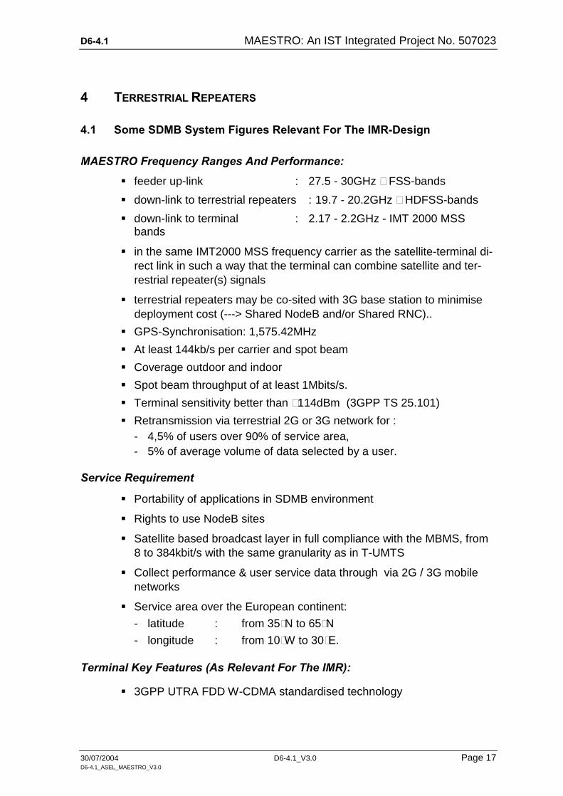
MAESTRO Frequency Ranges And Performance:
feeder up-link : 27.5 - 30GHz – FSS-bands
down-link to terrestrial repeaters : 19.7 - 20.2GHz – HDFSS-bands
down-link to terminal : 2.17 - 2.2GHz - IMT 2000 MSS bands
in the same IMT2000 MSS frequency carrier as the satellite-terminal di-rect link in such a way that the terminal can combine satellite and ter-restrial repeater(s) signals
terrestrial repeaters may be co-sited with 3G base station to minimise deployment cost (---> Shared NodeB and/or Shared RNC)..
GPS-Synchronisation: 1,575.42MHz
At least 144kb/s per carrier and spot beam
Coverage outdoor and indoor
Spot beam throughput of at least 1Mbits/s.
Terminal sensitivity better than –114dBm (3GPP TS 25.101)
Retransmission via terrestrial 2G or 3G network for : - 4,5% of users over 90% of service area, - 5% of average volume of data selected by a user.
Service Requirement
Portability of applications in SDMB environment
Rights to use NodeB sites
Satellite based broadcast layer in full compliance with the MBMS, from 8 to 384kbit/s with the same granularity as in T-UMTS
Collect performance & user service data through via 2G / 3G mobile networks
Service area over the European continent:
- latitude : from 35°N to 65°N
- longitude : from 10°W to 30°E.
Terminal Key Features (As Relevant For The IMR):
3GPP UTRA FDD W-CDMA standardised technology

D6-4.1 MAESTRO: An IST Integrated Project No. 507023
30/07/2004 D6-4.1_V3.0 Page 18 D6-4.1_ASEL_MAESTRO_V3.0
3GPP standardised handsets reception performances in IMT2000 satel-lite down-link frequency band (2.170 - 2.200GHz)
Multimode 3G terminals without additional reception chain: no simulta-neous reception or transmission through both modes
dual mode, GSM, UMTS, MBMS enabled
recombination of signals received from the satellite and the terrestrial repeaters using rake receiver
SDMB reception shall not prevent mobile network operations (idle mode: paging, location update; connected mode)
specific software package to configure the UMTS/MBMS protocol stack and implement media broadcast application enabling technology.
Standardised interfaces to 2G / 3G networks
Hub Requirements (As Relevant To The IMR)
controls the broadcast transmission in one or several spot beams
builds the 3GPP standardised W-CDMA down-link carriers
fixed Satellite System frequency band 5MHz carrier for direct satellite path.
the system is designed to allow several hubs to share the system ca-pacity and several BM-SC to share the capacity managed by the Hub

D6-4.1 MAESTRO: An IST Integrated Project No. 507023
30/07/2004 D6-4.1_V3.0 Page 19 D6-4.1_ASEL_MAESTRO_V3.0
4.2 View On Different Architectures Of Terrestrial Repeaters
The MAESTRO System is intended to apply different types of Terrestrial Repeat-ers according to the particular terrestrial topology. Nevertheless, hub characteris-tics in combination with the transmitted UMTS channels may determine only a re-stricted number of IMR variants; in principle this will become an issue when the decision has to be made up, either to transmit only the Uu via the satellite or the full set of e.g., Uu, Iub and Iur respectively. A final decision might be derived from the economical investigations and the resulting cheapest solution.
4.2.1 Families Of IMRs
Figure 4 depicts three principle IMR architecture solutions. They can be classified into sub groups either operating fully independently of existing environments or making use of it.
Rx-Receiver
De- coupling
Tx-Equipment
Tx-Amplif ier 1OOdB
Rx-Receiver
SharedNode B
Tx-Equipment
PrivateShared- RNC
Rx-Receiver
Tx-Amplif ier
Tx-Equipment
MAESTRO RNC-Emulator
On-Channel Repeater
Frequency Conversion Repeater
Shared NodeB Repeater
GPS-Synchronisat ion
MSS HDFSS HDFSS Iub / Iur
MSSMSSMSS
HDFSS
MSS
Uu
Uu
Figure 4: Three IMR-principle architecture types
4.2.2 Stand-Alone Repeaters Without Using Available Infrastructure
This type of repeaters follows the scheme given in Figure 4 on left-hand side and middle. A number of suitable terrestrial repeaters of this type is commercially available and applicable but all types burdened with a set of specific issues by their own with respect to the envisaged SDMB system.
This paragraph will describe very briefly some principle type of repeaters which will described subsequently more detailed in context with their specifications. Due to their technical appearance such repeaters are fairly not suitable to use or re-use

D6-4.1 MAESTRO: An IST Integrated Project No. 507023
30/07/2004 D6-4.1_V3.0 Page 20 D6-4.1_ASEL_MAESTRO_V3.0
existing communication infrastructure (such as NodeBs, RNCs, etc). Two exam-ples may be given to show the principles of such type of terrestrial repeaters:
On-Channel Repeater ("Enhancer"): This repeater type acts as a simple amplifier for the received signal. Specific measures have to be taken for keeping input and output signals strictly separated in order to avoid strong interference and feed-back. This repeater type is cheap but serviceable only in restricted areas (e.g., indoor application).
Frequency Conversion Repeater: This repeater type offers a reasonable technical concept in combination with a high degree of flexibility. Input and output do not conflict; measures need not be taken to avoid feed-back. This type of repeater is of medium cost and its most suitable installation may be in more dens crowded areas.
4.2.3 Repeaters Partly Using Available Infrastructure
This repeater type will make use of available communication infrastructure and follows the scheme given in Figure 4. It can be said that this challenging broadcast system will suffer of – apart from other issues – trip delays, path delays, process-ing delays, etc. and their balance. Furthermore, system synchronisation will play a strong role in the system which requires precise bit and frame synchronisation across both the satellite link and the supporting terrestrial links, in particular, when NodeBs and RNCs will be used. Consequently, the expected benefits of such a solution are high and must be able to compensate such really complex techniques and technologies. Two examples will stand for this type:
Architecture Sub-Variants Based On NodeB: Figure 4 and Figure 5 represents the Node-B based IMR functional architecture, reusing an existing terrestrial mobile network base station for to comply with the requirement MAE-D6-1.1-C-REQ-089. In addition to the stand-alone repeaters the following functional equipment has to be added:
a GPS receiver, providing a time reference to the NodeB
satellite reception equipment, providing the Iub traffic coming from the hub via a satellite
an equipment merging the unidirectional satellite Iub traffic and the ter-restrial Iub traffic coming from the UMTS PLMN, and providing synchro-nisation.
Finally, the NodeB needs to be upgraded for to use the IMT-2000 MSS satellite bands and to process the GPS signals.:
RNS/RNC Based Repeater The decision on a repeater solution based on an RNS/RNC-infrastructure for the time being needs both further study and experi-ence gain.

D6-4.1 MAESTRO: An IST Integrated Project No. 507023
30/07/2004 D6-4.1_V3.0 Page 21 D6-4.1_ASEL_MAESTRO_V3.0
The IMR logical architecture must match one of the two logical architectures of the SDMB hub, represented in the hub design document:
GPS
Node B
Iub antenna
unidirect. Iub +
synchro
Iub IBS/IDR terminal receiver
or DVB sat. demodulator
Ka band Rx unit
Rx antenna
IF
New equipment
Modified equipment
HTI Rx
Iub terrestrial
Figure 5: NodeB IMR functional architecture
the satellite transmits only an Uu interface data signal; therefore, the IMR acts as a repeater of this Uu signal, on-channel or with frequency conver-sion, as shown in Figure 6.
Radio Tx
Uu Radio
Rx
Uu Rx
antenna Tx
antenna
Figure 6: IMR architecture scheme for Uu-repeater
the satellite transmits an Iub interface signal; therefore, the IMR is NodeB based and contains a HTI Rx (Hub to IMR Receiver), as depicted in Figure 7. Such type of repeaters are required when making use of available communication infrastructure (e.g., NodeBs, RNCs, etc.)
Node B
Iub
antenna Rx antenna
HTI Rx
Iub terrestrial
Iub
Figure 7: IMR architecture scheme for Iub-repeater
D6-4.1 MAESTRO: An IST Integrated Project No. 507023
30/07/2004 D6-4.1_V3.0 Page 22 D6-4.1_ASEL_MAESTRO_V3.0
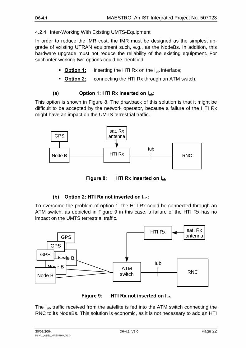
4.2.4 Inter-Working With Existing UMTS-Equipment
In order to reduce the IMR cost, the IMR must be designed as the simplest up-grade of existing UTRAN equipment such, e.g., as the NodeBs. In addition, this hardware upgrade must not reduce the reliability of the existing equipment. For such inter-working two options could be identified:
Option 1: inserting the HTI Rx on the Iub interface;
Option 2: connecting the HTI Rx through an ATM switch.
(a) Option 1: HTI Rx inserted on Iub:
This option is shown in Figure 8. The drawback of this solution is that it might be difficult to be accepted by the network operator, because a failure of the HTI Rx might have an impact on the UMTS terrestrial traffic.
Node B RNC HTI Rx
GPS sat. Rx antenna
Iub
Figure 8: HTI Rx inserted on Iub
(b) Option 2: HTI Rx not inserted on Iub:
To overcome the problem of option 1, the HTI Rx could be connected through an ATM switch, as depicted in Figure 9 in this case, a failure of the HTI Rx has no impact on the UMTS terrestrial traffic.
Node B
GPS HTI Rx
RNC ATM
switch
sat. Rx antenna
Iub Node B
GPS
Node B
GPS
Figure 9: HTI Rx not inserted on Iub
The Iub traffic received from the satellite is fed into the ATM switch connecting the RNC to its NodeBs. This solution is economic, as it is not necessary to add an HTI

D6-4.1 MAESTRO: An IST Integrated Project No. 507023
30/07/2004 D6-4.1_V3.0 Page 23 D6-4.1_ASEL_MAESTRO_V3.0
Rx, an antenna, etc. in each NodeB. Only one set of these devices need to be in-tegrated in the RNC location. This will provide SDMB capability to the whole No-deBs connected to this RNC.
(c) Option 2 Refinement:
In option 2, the Iub traffic received from the satellite cannot be simply fed into the ATM switch as only one Q.2630 VC exists, and the AAL5 uses one ALCAP VC and one NBAP VC. Concerning the data traffic over AAL2, option 2 works as the ALCAP VCI and VPI can be changed.
As shown in Figure 10, a listening probe close to the RNC could be inserted on Iub. This probe enables the HTI Rx to listen to the Iub traffic exchanged with the RNC. This probe could be either a high-impedance listening probe inserted on E1/Iub, or a feature of the ATM switch.
HTI Rx
RNC listening probe
ATM switch
Rx antenna
Iub Node B
GPS
Node B
GPS
Node B
GPS
Figure 10: RNC based IMR
Another issue in this case is the synchronisation of the NodeBs connected to one HTI Rx. As the HTI Rx is only capable to synchronise one NodeB, the problem arises how and by what the other NodeBs can be be synchronised, too.
TBC: in Alcatel Node B, check if distinct ATM circuits can be used for common channels.
TBC: check that no problem with AAL5 circuits.

D6-4.1 MAESTRO: An IST Integrated Project No. 507023
30/07/2004 D6-4.1_V3.0 Page 24 D6-4.1_ASEL_MAESTRO_V3.0
5 IMR SPECIFICATIONS
5.1 Description And Specifications Of The IMR-Variants
5.1.1 Scheme For Embedding IMRs In An SDMB Environment
contentprovider
private RNC NodeB
(1)
UE
<---- I/ F to nat ional GSM/ GPRS network ---->
IMR - Environment
Iur*- data
both down-link streamstreated like mult iplepath propagated dtreams
booster, Txantenna
privateIub-data
Uu- data
UE- Interface MSS2.17 - 2.2OGHz (UMTS) BM_
SC
delay
SPACE2.17 - 2.2OGHz MSS IMT2OOO bandsSDMB W- CDMA
SPACE I/ F19.7 - 2O.2GHz HDFSS
IMR
Uu- data
Uu- data
Uu-data
<---- I/ F to nat ional GSM/ GPRS network ---->
GPS I/ F
Uu- data
Iur*- I/ F
privateUu-data
shared node I/ F
SPACE I/ FIub- data
SPACE I/ F2.17 - 2.2OGHz MSS
SPACE Feeder I/ F 27.5 -3O.OGHz FSS
27.5 -3O.OGHz FSS
SDMB band W-CDMA
Iur*- data
Uu- data
Uu-data
Iub- data
Figure 11: The Basic System – IMR Embedding
D6-4.1 MAESTRO: An IST Integrated Project No. 507023
30/07/2004 D6-4.1_V3.0 Page 25 D6-4.1_ASEL_MAESTRO_V3.0
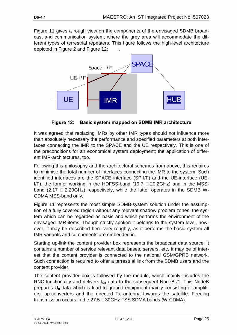
Figure 11 gives a rough view on the components of the envisaged SDMB broad-cast and communication system, where the grey area will accommodate the dif-ferent types of terrestrial repeaters. This figure follows the high-level architecture depicted in Figure 2 and Figure 12: .
UE IMR HUB
SPACE
UE- I/ F
Space- I/ F
Figure 12: Basic system mapped on SDMB IMR architecture
It was agreed that replacing IMRs by other IMR types should not influence more than absolutely necessary the performance and specified parameters at both inter-faces connecting the IMR to the SPACE and the UE respectively. This is one of the preconditions for an economical system deployment; the application of differ-ent IMR-architectures, too.
Following this philosophy and the architectural schemes from above, this requires to minimise the total number of interfaces connecting the IMR to the system. Such identified interfaces are the SPACE interface (SP-I/F) and the UE-interface (UE-I/F), the former working in the HDFSS-band (19.7 – 20.2GHz) and in the MSS-band (2.17 – 2.20GHz) respectively, while the latter operates in the SDMB W-CDMA MSS-band only.
Figure 11 represents the most simple SDMB-system solution under the assump-tion of a fully covered region without any relevant shadow problem zones; the sys-tem which can be regarded as basic and which performs the environment of the envisaged IMR items. Though strictly spoken it belongs to the system level, how-ever, it may be described here very roughly, as it performs the basic system all IMR variants and components are embedded in.
Starting up-link the content provider box represents the broadcast data source; it contains a number of service relevant data bases, servers, etc. It may be of inter-est that the content provider is connected to the national GSM/GPRS network. Such connection is required to offer a terrestrial link from the SDMB users and the content provider.
The content provider box is followed by the module, which mainly includes the RNC-functionality and delivers Iub-data to the subsequent NodeB /1. This NodeB prepares Uu-data which is lead to ground equipment mainly consisting of amplifi-ers, up-converters and the directed Tx antenna towards the satellite. Feeding transmission occurs in the 27.5 – 30GHz FSS SDMA bands (W-CDMA).
D6-4.1 MAESTRO: An IST Integrated Project No. 507023
30/07/2004 D6-4.1_V3.0 Page 26 D6-4.1_ASEL_MAESTRO_V3.0
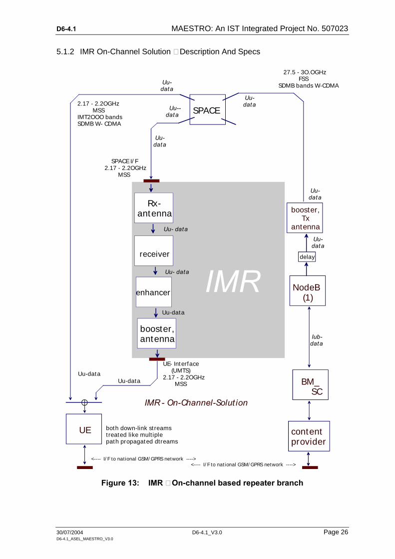
5.1.2 IMR On-Channel Solution – Description And Specs
contentprovider
NodeB (1)
UE
<---- I/ F to nat ional GSM/ GPRS network ---->
IMR - On-Channel-Solut ion
both down-link st reamstreated like mult iplepath propagated dtreams
enhancer
booster, Txantenna
booster,antenna
Uu-data
Uu- data
SPACE I/ F2.17 - 2.2OGHz MSS
UE- Interface (UMTS)2.17 - 2.2OGHz MSS BM_
SC
delay
SPACE
27.5 - 3O.OGHz FSSSDMB bands W-CDMA
2.17 - 2.2OGHz MSS IMT2OOO bandsSDMB W- CDMA
IMR
Uu- data Uu--
data
Uu- data
Uu-data
Rx-antenna
<---- I/ F to nat ional GSM/ GPRS network ---->
Uu- data
Iub- data
Uu- data
Uu- data
Uu- data
receiver
Uu-data
Figure 13: IMR – On-channel based repeater branch
D6-4.1 MAESTRO: An IST Integrated Project No. 507023
30/07/2004 D6-4.1_V3.0 Page 27 D6-4.1_ASEL_MAESTRO_V3.0
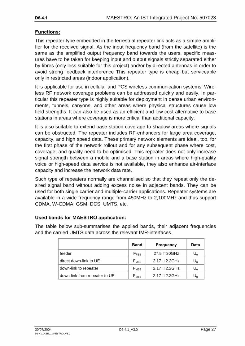
Functions:
This repeater type embedded in the terrestrial repeater link acts as a simple ampli-fier for the received signal. As the input frequency band (from the satellite) is the same as the amplified output frequency band towards the users, specific meas-ures have to be taken for keeping input and output signals strictly separated either by fibres (only less suitable for this project) and/or by directed antennas in order to avoid strong feedback interference This repeater type is cheap but serviceable only in restricted areas (indoor application).
It is applicable for use in cellular and PCS wireless communication systems. Wire-less RF network coverage problems can be addressed quickly and easily. In par-ticular this repeater type is highly suitable for deployment in dense urban environ-ments, tunnels, canyons, and other areas where physical structures cause low field strengths. It can also be used as an efficient and low-cost alternative to base stations in areas where coverage is more critical than additional capacity.
It is also suitable to extend base station coverage to shadow areas where signals can be obstructed. The repeater includes RF-enhancers for large area coverage, capacity, and high speed data. These primary network elements are ideal, too, for the first phase of the network rollout and for any subsequent phase where cost, coverage, and quality need to be optimised. This repeater does not only increase signal strength between a mobile and a base station in areas where high-quality voice or high-speed data service is not available, they also enhance air-interface capacity and increase the network data rate.
Such type of repeaters normally are channelised so that they repeat only the de-sired signal band without adding excess noise in adjacent bands. They can be used for both single carrier and multiple-carrier applications. Repeater systems are available in a wide frequency range from 450MHz to 2,100MHz and thus support CDMA, W-CDMA, GSM, DCS, UMTS, etc.
Used bands for MAESTRO application:
The table below sub-summarises the applied bands, their adjacent frequencies and the carried UMTS data across the relevant IMR-interfaces.
Band Frequency Data
feeder FFSS 27.5 – 30GHz Uu
direct down-link to UE FMSS 2.17 – 2.2GHz Uu
down-link to repeater FMSS 2.17 – 2.2GHz Uu
down-link from repeater to UE FMSS 2.17 – 2.2GHz Uu
D6-4.1 MAESTRO: An IST Integrated Project No. 507023
30/07/2004 D6-4.1_V3.0 Page 28 D6-4.1_ASEL_MAESTRO_V3.0
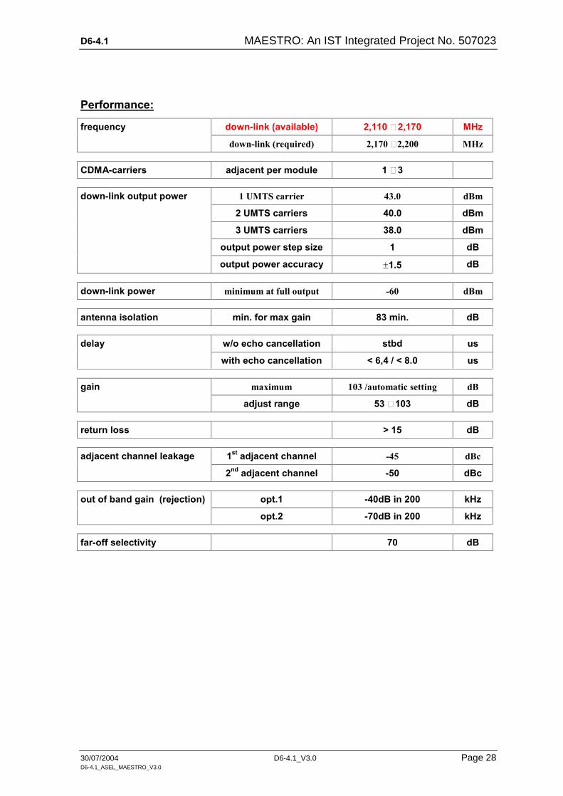
Performance:
frequency down-link (available) 2,110 – 2,170 MHz
down-link (required) 2,170 – 2,200 MHz
CDMA-carriers adjacent per module 1 – 3
down-link output power 1 UMTS carrier 43.0 dBm
2 UMTS carriers 40.0 dBm
3 UMTS carriers 38.0 dBm
output power step size 1 dB
output power accuracy 1.5 dB
down-link power minimum at full output -60 dBm
antenna isolation min. for max gain 83 min. dB
delay w/o echo cancellation stbd us
with echo cancellation < 6,4 / < 8.0 us
gain maximum 103 /automatic setting dB
adjust range 53 – 103 dB
return loss > 15 dB
adjacent channel leakage 1st adjacent channel -45 dBc
2nd adjacent channel -50 dBc
out of band gain (rejection) opt.1 -40dB in 200 kHz
opt.2 -70dB in 200 kHz
far-off selectivity 70 dB

D6-4.1 MAESTRO: An IST Integrated Project No. 507023
30/07/2004 D6-4.1_V3.0 Page 29 D6-4.1_ASEL_MAESTRO_V3.0
Interfaces:
Remarks:
pros for this repeater type: cons for this repeater type:
cheap; "plug´n´play" antenna set required
simple and cheap indoor solution difficult input/output de-coupling
stand-alone capability

D6-4.1 MAESTRO: An IST Integrated Project No. 507023
30/07/2004 D6-4.1_V3.0 Page 30 D6-4.1_ASEL_MAESTRO_V3.0
5.1.3 Frequency Conversion IMR Solution - Descriptions And Specs
contentprovider
NodeB (1)
UE
<---- I/ F to nat ional GSM/ GPRS network ---->
IMR - Frequency Conversion Solut ion
both down-link streamstreated like mult iplepath propagated dtreams
DC-downcon.
booster, Txantenna
booster,antenna
Uu-data
Uu- data
SPACE I/ F 19.7 - 2O.2GHz HDFSS
UE- Interface (UMTS)2.17 - 2.2OGHz MSS BM_
SC
delay
SPACE
mult ipleof 8 frames
27.5 - 3O.OGHz FSSSDMB bands W-CDMA
2.17 - 2.2OGHz MSS IMT2OOO bandsSDMB W- CDMA
IMR
Uu- data Uu--
data
Uu- data
Uu-data
Rx-antenna
<---- I/ F to nat ional GSM/ GPRS network ---->
Uu- data
Iub- data
Uu- data
Uu- data
Uu- data
receiver
Uu-data
Figure 14: IMR – frequency conversion based repeater branch
D6-4.1 MAESTRO: An IST Integrated Project No. 507023
30/07/2004 D6-4.1_V3.0 Page 31 D6-4.1_ASEL_MAESTRO_V3.0
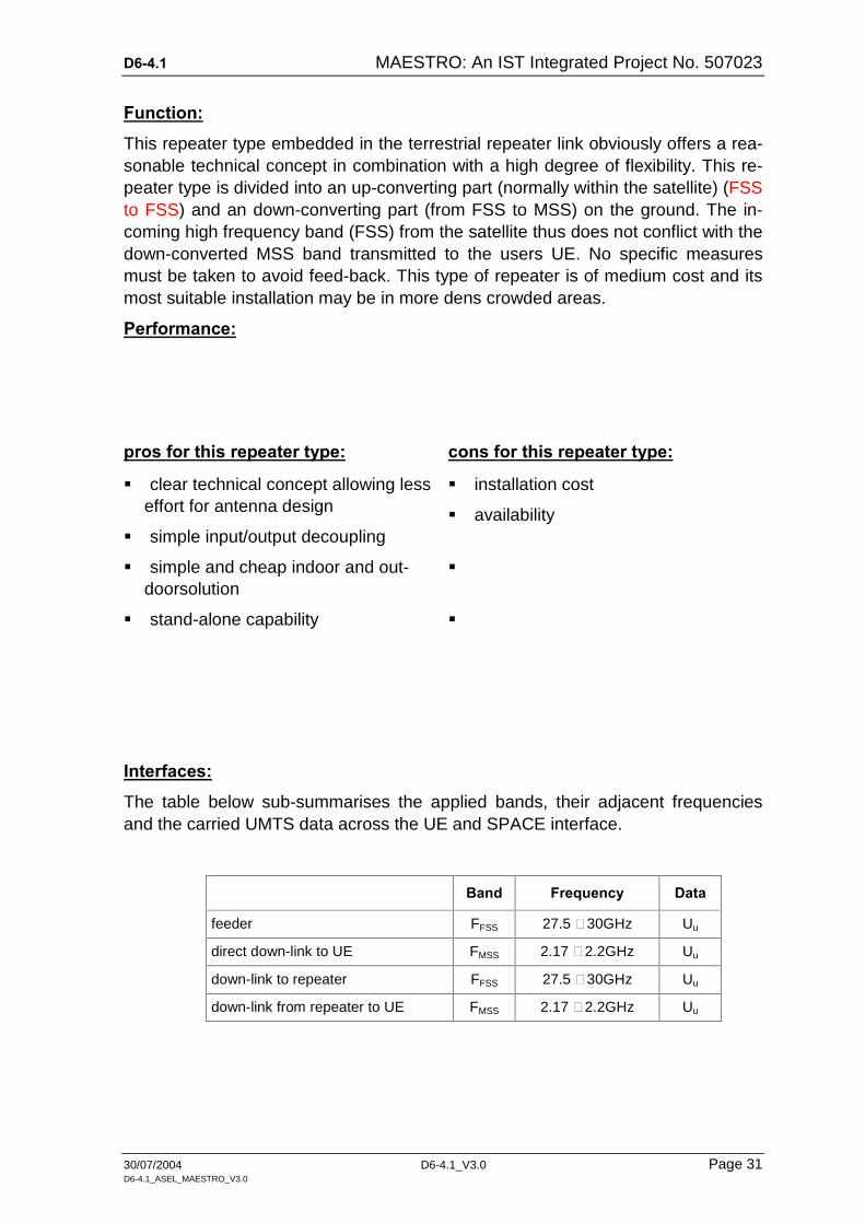
Function:
This repeater type embedded in the terrestrial repeater link obviously offers a rea-sonable technical concept in combination with a high degree of flexibility. This re-peater type is divided into an up-converting part (normally within the satellite) (FSS to FSS) and an down-converting part (from FSS to MSS) on the ground. The in-coming high frequency band (FSS) from the satellite thus does not conflict with the down-converted MSS band transmitted to the users UE. No specific measures must be taken to avoid feed-back. This type of repeater is of medium cost and its most suitable installation may be in more dens crowded areas.
Performance:
pros for this repeater type: cons for this repeater type:
clear technical concept allowing less effort for antenna design
simple input/output decoupling
installation cost
availability
simple and cheap indoor and out-doorsolution
stand-alone capability
Interfaces:
The table below sub-summarises the applied bands, their adjacent frequencies and the carried UMTS data across the UE and SPACE interface.
Band Frequency Data
feeder FFSS 27.5 – 30GHz Uu
direct down-link to UE FMSS 2.17 – 2.2GHz Uu
down-link to repeater FFSS 27.5 – 30GHz Uu
down-link from repeater to UE FMSS 2.17 – 2.2GHz Uu

D6-4.1 MAESTRO: An IST Integrated Project No. 507023
30/07/2004 D6-4.1_V3.0 Page 32 D6-4.1_ASEL_MAESTRO_V3.0
5.1.4 NodeB Based IMR Solution - Descriptions And Specs
contentprovider
private RNC NodeB
(1)
UE
Node B (2)
GPS-receiver
<---- I/ F to nat ional GSM/ GPRS network ---->
IMR - NodeB-Solut ion
Iur*- data
both down-link streamstreated like mult iplepath propagated dtreams
receiver
booster, Txantenna
booster,antenna
GPS - Sync
Iur*-data
privateIub-data
Uu-data
Uu- data
SPACE I/ F19.7 - 2O.2GHz HDFSS
UE- Interface (UMTS)2.17 - 2.2OGHz MSS-band
private Uu-data
BM_ SC
delay
Iur*-data
booster, Txantenna
SPACE
Iur*- data
multipleof 8 frames
27.5 - 3O.OGHz FSSSDMB bands W-CDMA
2.17 - 2.2OGHz MSS IMT2OOO bandsSDMB W- CDMA
IMR
IMR
Uu- data Iur*-
data
SPACE Feeder I/ F 27.5 - 3O.OGHz FSS
Uu- data
Iur*- data
Iur*-data
Uu-data
Rx-antenna
RNCemul
<---- I/ F to nat ional GSM/ GPRS network ---->
GPS I/ F
Uu- data
Iur*- I/ F
privateUu-data
shared node I/ F
Iur*- data
Iub- data
Figure 15: IMR - NodeB based repeater branch

D6-4.1 MAESTRO: An IST Integrated Project No. 507023
30/07/2004 D6-4.1_V3.0 Page 33 D6-4.1_ASEL_MAESTRO_V3.0
Function:
Figure 15 represents the NodeB based IMR functional architecture, reusing an existing terrestrial mobile network base station in the IMR-branch to comply with the requirement MAE-D6-1.1-C-REQ-089. Though the ambitious topic, Maestro to share an installed private NodeB with a private network provider, sounds reason-able for making use of the existing communication infrastructure, in equal measure this enlarges the number of additional issues sizabely.
In order to simplify and concentrate the technical discussion in an initial step it is assumed to base all subsequent considerations on an Alcatel NodeB V2.
This repeater solution to apply a standard NodeB burdens the system concept with numerous technical issues, mainly in the area of synchronisation, propagation time delays and processing time delays. This is illustrated in Figure 15 in form of a GPS receiver assigned to the repeater branch catering for bit synchronism and frame synchronism. between Hub and the repeater NodeB/2. This also requires a spe-cific synchronisation access to the SUMU on the Iub – side. Such access is planned and prepared but not implemented yet an needs further HW and SW ad-aptation development.
Unfortunately, such synchronism is not sufficient, as propagation delay has to be balanced, too, in the repeater NodeB/2. This balance can only be executed cor-rectly by sending both Uu-data and Iub-data via satellite either to the UE directly as well as processed. The reason for this is that the Uu data has to be delayed within the Hub in order to meet later-on at the UE interface frame number and assigned frame content timely correct. The required delay steps may be adjusted with steps of multiples of 8 frames duration.
On the Iub – side of the repeater NodeB/2 provisions have to be made to synchro-nise both the received data from the satellite as well as the data streams in the private part of the NodeB/2. Additionally private Iub-data have to be multiplexed, at least functional, with the Maestro Iub-data. As Maestro is a broadcast system, i.e., one-way Iub-data, supplementary measures have to be taken to allow the NodeB/2 dialogues for cell set-up, common channel set-up, mismatch balance for UMTS frame synchronisation, ARM cell transmission, etc.
Performance:
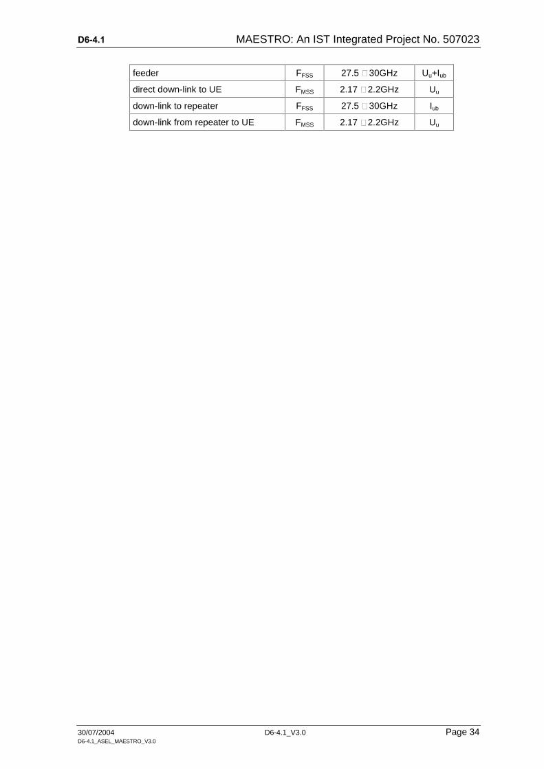
Interfaces:
The table below sub-summarises the applied bands, their adjacent frequencies and the carried UMTS data.
Band Frequency Data
D6-4.1 MAESTRO: An IST Integrated Project No. 507023
30/07/2004 D6-4.1_V3.0 Page 34 D6-4.1_ASEL_MAESTRO_V3.0
feeder FFSS 27.5 – 30GHz Uu+Iub
direct down-link to UE FMSS 2.17 – 2.2GHz Uu
down-link to repeater FFSS 27.5 – 30GHz Iub
down-link from repeater to UE FMSS 2.17 – 2.2GHz Uu

D6-4.1 MAESTRO: An IST Integrated Project No. 507023
30/07/2004 D6-4.1_V3.0 Page 35 D6-4.1_ASEL_MAESTRO_V3.0
pros for this repeater type: cons for this repeater type:
Re-use of NodeB infrastructure (power supply, etc,)
Rake requirements (20us window)
System synchronisation required
Suitable NodeB locations and posi-tions

D6-4.1 MAESTRO: An IST Integrated Project No. 507023
30/07/2004 D6-4.1_V3.0 Page 36 D6-4.1_ASEL_MAESTRO_V3.0
5.1.5 IMR I/F To Outside World – Space I/Fs

D6-4.1 MAESTRO: An IST Integrated Project No. 507023
30/07/2004 D6-4.1_V3.0 Page 37 D6-4.1_ASEL_MAESTRO_V3.0
5.1.6 IMR I/F To Outside World – UE I/F

D6-4.1 MAESTRO: An IST Integrated Project No. 507023
30/07/2004 D6-4.1_V3.0 Page 38 D6-4.1_ASEL_MAESTRO_V3.0
5.2 Detail Specification Of Dedicated Components
In this chapter it is intended to describe some complex specifications (just like this one fore NodeB), which hardly fit into a integral table work and additionally require illustrations.
5.2.1 Transmit Path OF NodeB
(a) UMTS (UTRA FDD) NodeB General Radio Parameters:
Tx-power : 20W +/- 1dB, 43dBm (3GPP TS25.104)
Reference sensitivity : -123dBm at 12.2kb/s, SF = 64, BER less or equal10-3
Channel bandwidth : 5MHz
Frequency range : UTRA FDD
Combiner type : wide-band combining
(b) Frequency Bands:
transmit frequency band : 2,110MHz – 2,170MHz (terrestrial UMTS)
Tx-mid-frequency : 2,140MHz (terrestrial UMTS)
transmit frequency band : 2,170MHz – 2,200MHz (UMTS-satellite band)
Tx-mid-frequency : 2,185MHz (UMTS-satellite band)
The local oscillators within the Tx-block are adjustable to support UMTS carriers within these RF bands. The adjustable oscillators will settle within 10ms after a frequency change command. The RF filters within the Tx module support the full 60MHz RF bandwidth without any tuning.
(c) Capacity Per Cell: Within the NodeB should be no limitation in order to support up to 120 users and 1,920kb/s per cell. This cell capacity cannot be achieved today but will be target for the next future.
Also the restricted capacity for base-band processing on NodeB-level in the future could be set to a maximum of 18 cells (6x3) thus with 75% load and 75% voice users in total. Fully equipped the Node may handle up to 1,215 users (18 x 0.75 x 0.75 x 120users ) and 25,920kb/s. The today base-band processing per cell allows support up to 75 users and 1,536kb/s per cell. For traffic mix models the following rough estimation for Basis Band Processing-module dimensioning can be drawn up:
K + L + M + N 75 user channels K x 12.2kb/s + L x 64kb/s + M x 128kb/s + N x 384kb/s 1,536 kb/s
where:
K = number of AMR users
D6-4.1 MAESTRO: An IST Integrated Project No. 507023
30/07/2004 D6-4.1_V3.0 Page 39 D6-4.1_ASEL_MAESTRO_V3.0
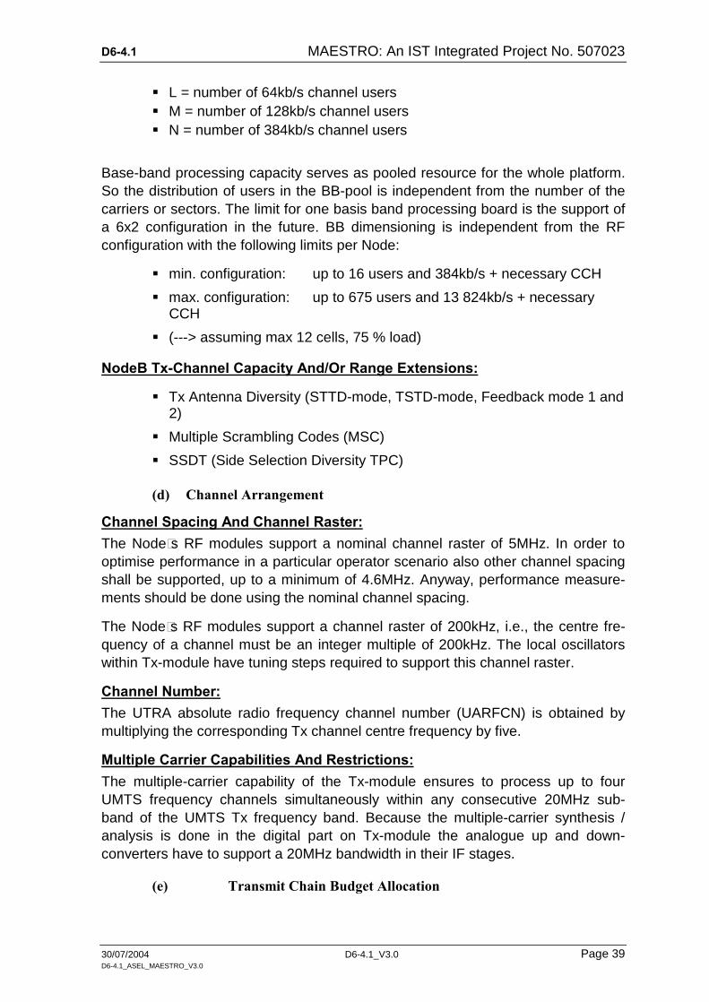
L = number of 64kb/s channel users M = number of 128kb/s channel users N = number of 384kb/s channel users
Base-band processing capacity serves as pooled resource for the whole platform. So the distribution of users in the BB-pool is independent from the number of the carriers or sectors. The limit for one basis band processing board is the support of a 6x2 configuration in the future. BB dimensioning is independent from the RF configuration with the following limits per Node:
min. configuration: up to 16 users and 384kb/s + necessary CCH
max. configuration: up to 675 users and 13 824kb/s + necessary CCH
(---> assuming max 12 cells, 75 % load)
NodeB Tx-Channel Capacity And/Or Range Extensions:
Tx Antenna Diversity (STTD-mode, TSTD-mode, Feedback mode 1 and 2)
Multiple Scrambling Codes (MSC)
SSDT (Side Selection Diversity TPC)
(d) Channel Arrangement
Channel Spacing And Channel Raster: The Node´s RF modules support a nominal channel raster of 5MHz. In order to optimise performance in a particular operator scenario also other channel spacing shall be supported, up to a minimum of 4.6MHz. Anyway, performance measure-ments should be done using the nominal channel spacing.
The Node´s RF modules support a channel raster of 200kHz, i.e., the centre fre-quency of a channel must be an integer multiple of 200kHz. The local oscillators within Tx-module have tuning steps required to support this channel raster.
Channel Number: The UTRA absolute radio frequency channel number (UARFCN) is obtained by multiplying the corresponding Tx channel centre frequency by five.
Multiple Carrier Capabilities And Restrictions: The multiple-carrier capability of the Tx-module ensures to process up to four UMTS frequency channels simultaneously within any consecutive 20MHz sub-band of the UMTS Tx frequency band. Because the multiple-carrier synthesis / analysis is done in the digital part on Tx-module the analogue up and down-converters have to support a 20MHz bandwidth in their IF stages.
(e) Transmit Chain Budget Allocation

D6-4.1 MAESTRO: An IST Integrated Project No. 507023
30/07/2004 D6-4.1_V3.0 Page 40 D6-4.1_ASEL_MAESTRO_V3.0
The reference point for transmitter performance measurements is the NodeB an-tenna connector. The following measurements should be executed there:
base station output power tests,
occupied bandwidth test,
adjacent channel leakage power ratio tests (ACLR),
spurious emissions tests, transmit inter-modulation test.
Base Station Maximum Output Power: The maximum output power is the mean power level per carrier measured at the reference point when the carrier power is set to maximum available power. For the multiple-carrier Tx the available output power could be distributed to up to four car-riers. In the tables below the sum of all carriers is given. In case of only one carrier the total output power should be available for this carrier. The following require-ments Table 1 are applicable for the applied NodeB:
Table 1: NodeB power budget
NodeB output power normal condit. extreme condit.
minimum value [W] 14.79 12.88
typical value [W] 20.89 20.65
maximum value [W] 29.51 33.11
minimum value [dBm] 41.70 41.10
typical value [dBm] 43.20 43.15
maximum value [dBm] 44.70 45.20
tolerance [+/- dBm] 1.50 2.50
Tx-module output power normal condit. extreme condit.
nominal output power [W] 29.5 29.5
extreme output power [W] 44.7 44.7
output power tolerance [+/- dB] 1.0 1.5
minimum output power [dBm] 43.7 43.2
typical output power [dBm] 44.7 44.7
minimum output power [dBm] 45.7 46.2
NodeB module insertion loss normal condit. extreme condit.
minimum loss in Tx-band [W] 0.20 0.20
typical loss in Tx-band [W] 0.60 0.65
maximum loss in Tx-band [W] 1.00 1.10
RF-cable insertion loss TRx-ANT ANT -BTS

D6-4.1 MAESTRO: An IST Integrated Project No. 507023
30/07/2004 D6-4.1_V3.0 Page 41 D6-4.1_ASEL_MAESTRO_V3.0
minimum loss in Tx-band [dBm] 0.30 0.50
typical loss in Tx-band [dBm] 0.35 0.55
maximum loss in Tx-band [dBm] 0.40 0.60
(f) Frequency Error: All frequencies and clocks within the Node shall be derived from the same source. The modulated carrier frequency is measured over a period of one power control group (one radio timeslot of 666.6us). The following effects may contribute to the modulated carrier frequency error:
stability of the common frequency source (master oscillator of the Node, which determines the long-term stability of the carrier frequency. If the master oscillator is locked to the clock from the Iub interface, then clock stability will refer to the stability of the Iub clock.
clock distribution within the platform´s cabinet. Low frequency noise and spurs up to several kHz contribute to the frequency error. To minimise these effects, a clock cleanup circuit shall be used within the Tx-module with a loop bandwidth of less than 10Hz.
TEU internal effects like noise and spurs on the TEU internal clock dis-tribution, low frequency local oscillator phase noise or spurs and power amplifier
Table 2below allocates the allowed overall frequency error to the different sources.
Table 2: Tx frequency error budget
Tx frequency error budget error
[+/- ppm] error at RF
[+/- Hz]
platform master oscillator 0.020 29.5
clock distribution inside cabinet 0.005 44.7
Tx-module 0.025 1.5
calculated platform frequency error 0.050 43.2
required platform frequency error 0.050 44.7
(h) Output RF-Spectrum Emissions From budget allocation point of view, the RF spectrum emission requirements can be divided into two categories:
requirements inside the UMTS transmit band (2,110 – 2,170MHz) and close to the band edges. In this frequency band Tx has to fulfil the re-quirements because the Tx filter within ANT does not provide any addi-tional suppression beside the normal in-band insertion loss.
for the MAESTRO application the Tx filter requires a shift of the filter mid-frequency from 2,140 to 2,185MHz.

D6-4.1 MAESTRO: An IST Integrated Project No. 507023
30/07/2004 D6-4.1_V3.0 Page 42 D6-4.1_ASEL_MAESTRO_V3.0
requirements outside the UMTS transmit band. Here the Tx filter of the Antenna Network provides additional suppression of unwanted frequen-cies.
Occupied bandwidth is a measure of the bandwidth containing 99% of the total integrated power for transmitted spectrum and is centred on the assigned channel frequency. The occupied channel bandwidth shall be less than 5MHz at Tx output.
2.5 2.7 3.5
-15 0
Frequency separation f from the carrier [M Hz]
Pow
er d
ensi
ty in
30k
Hz
[dB
m]
f_offsetmax
-20
-25
-30
-35
-40
Pow
er d
ensi
ty in
1 M
Hz
[dB
m]
-5
-10
-15
-20
-25
7.5
P = 39 dBmP = 39 dBm
P = 43 dBmP = 43 dBm
P = 31 dBmP = 31 dBm
Illustrative diagram of spectrum em ission mask
Figure 16: Spectrum emission mask at reference point
The platforms Tx emissions shall not exceed the maximum level specified in Table 3 and also shown in Figure 16 for the appropriate maximum output power, in the frequency range from f = 2.5MHz to f_offsetmax from the carrier frequency, where:
f is the separation between the carrier frequency and the nominal -3dB point of the measuring filter closest to the carrier frequency.
f_offset is the separation between the carrier frequency and the centre of the measuring filter.
f_ offsetmax is either 12.5MHz or the offset to the UMTS-Tx band edge.
Table 3: Spectrum emission mask values for different output power
spectrum emission mask values for output power P<43dBm
frequency offset of measurement filter
–3dB-point, f
frequency offset of measurement filter centre frequency
f_offset
maximum level at TRx-output
maximum level at antenna output
Measure. bandwidth
2,5 < f <2.7MHz 2.515 < f_offset < 2.715MHz -13.15dBm -14dBm 30kHz
2,7 < f <3.5MHz 2.715 < f_offset<3.515MHz -13.15 - 15 -14 - 1.5 30kHz

D6-4.1 MAESTRO: An IST Integrated Project No. 507023
30/07/2004 D6-4.1_V3.0 Page 43 D6-4.1_ASEL_MAESTRO_V3.0
(f_offset-2.715)dBm (f_offset-2.715)dBm
see note below 3.515 < f_offset<4.000MHz -25.15dBm -26dBm 30kHz
3.5 < f MHz 4.000 <f_offset<f_offset max -12.15dBm -13dBm 1MHz
spectrum emission mask values for output power P>43dBm 2,5 < f < 2.7MHz 2.515 < f_offset < 2.715MHz -13.15dBm -14dBm 30kHz
2,7 < f < 3.5MHz 2.715 < f_offset < 3.515MHz -13.15-15 (f_offset-2.715)dBm
-14-1.5 (f_offset-2.715)dBm
30kHz
see note below 3.515 < f_offset < 4.000MHz -25.15dBm -26dBm 30kHz
3.5 <f < 7,5MHz 4 < f_offset < 8MHz -12.15dBm -13dBm 1MHz
7.5 <f MHz 8 < f_offset < f_offset max P - 55.15dBm P - 56dBm 1MHz
spectrum emission mask values for output power 31 < P < 39dBm
2,5 < f <2.7MHz 2.515 < f_offset < 2.715MHz P - 52.15dBm P - 53dBm 30kHz
2,7 < f < 3.5MHz 2.715 < f_offset < 3.515MHz
P - 52.15-15 (f_offset-2.715)dBm
P-14-1.5 (f_offset-2.715)dBm
30kHz
see note below 3.515 < f_offset < 4.000MHz P - 64.15dBm P - 65dBm 30kHz
3.5 < f < 7,5MHz 4 <f_offset < 8MHz P - 51.15dBm P - 52dBm 1MHz
7.5 < f MHz 8 < f_offset < f_offset max P - 55.15dBm P - 56dBm 1MHz
spectrum emission mask values for output power P < 31dBm
2,5 < f < 2.7MHz 2.515 < f_offset < 2.715MHz - 21.15dBm - 22dBm 30kHz
2,7 < f < 3.5MHz 2.715 < f_offset < 3.515MHz
P - 52.15-15 (f_offset-2.715)dBm
P-22-1.5 (f_offset-2.715)dBm
30kHz
see note below 3.515 < f_offset < 4.000MHz -33,15dBm - 34dBm 30kHz
3.5 < f < 7,5MHz 4 <f _offset < 8MHz - 20.15dBm P 21dBm 1MHz
7.5<f MHz 8 < f_offset < f_offset max - 24.15dBm - 25dBm 1MHz
Note: a minimum insertion loss of 0.85dB is assumed for the TX to antenna con-nector
(i) Adjacent Channel Leakage Ratio (ACLR): Adjacent Channel Leakage power Ratio (ACLR) is the ratio of the average power centred on the assigned channel frequency to the average power centred on an adjacent channel frequency. In both cases the average power is measured with a filter that has Root Raised Cosine (RRC) filter response with roll-off factor 0.22 and a bandwidth equal to the chip rate. The requirements below shall apply for all configurations of TRx (single carrier or multiple carrier) and for all operating modes foreseen.
Table 4: Adjacent channel leakage ratio at TX and platform output
adjacent channel offset below the first or above the last carrier frequency used ACLR limit ACLR typ
5MHz 45dB 48dB
D6-4.1 MAESTRO: An IST Integrated Project No. 507023
30/07/2004 D6-4.1_V3.0 Page 44 D6-4.1_ASEL_MAESTRO_V3.0
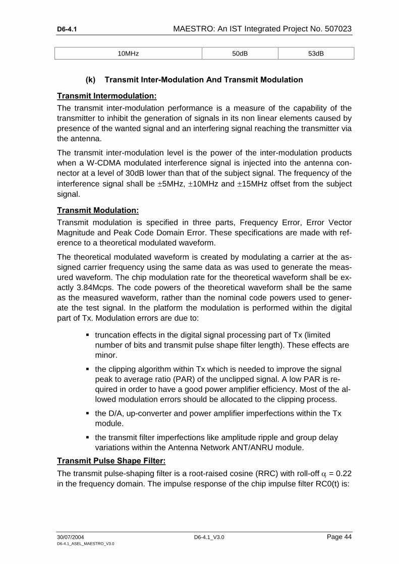
10MHz 50dB 53dB
(k) Transmit Inter-Modulation And Transmit Modulation
Transmit Intermodulation: The transmit inter-modulation performance is a measure of the capability of the transmitter to inhibit the generation of signals in its non linear elements caused by presence of the wanted signal and an interfering signal reaching the transmitter via the antenna.
The transmit inter-modulation level is the power of the inter-modulation products when a W-CDMA modulated interference signal is injected into the antenna con-nector at a level of 30dB lower than that of the subject signal. The frequency of the interference signal shall be 5MHz, 10MHz and 15MHz offset from the subject signal.
Transmit Modulation: Transmit modulation is specified in three parts, Frequency Error, Error Vector Magnitude and Peak Code Domain Error. These specifications are made with ref-erence to a theoretical modulated waveform.
The theoretical modulated waveform is created by modulating a carrier at the as-signed carrier frequency using the same data as was used to generate the meas-ured waveform. The chip modulation rate for the theoretical waveform shall be ex-actly 3.84Mcps. The code powers of the theoretical waveform shall be the same as the measured waveform, rather than the nominal code powers used to gener-ate the test signal. In the platform the modulation is performed within the digital part of Tx. Modulation errors are due to:
truncation effects in the digital signal processing part of Tx (limited number of bits and transmit pulse shape filter length). These effects are minor.
the clipping algorithm within Tx which is needed to improve the signal peak to average ratio (PAR) of the unclipped signal. A low PAR is re-quired in order to have a good power amplifier efficiency. Most of the al-lowed modulation errors should be allocated to the clipping process.
the D/A, up-converter and power amplifier imperfections within the Tx module.
the transmit filter imperfections like amplitude ripple and group delay variations within the Antenna Network ANT/ANRU module.
Transmit Pulse Shape Filter: The transmit pulse-shaping filter is a root-raised cosine (RRC) with roll-off = 0.22 in the frequency domain. The impulse response of the chip impulse filter RC0(t) is:

D6-4.1 MAESTRO: An IST Integrated Project No. 507023
30/07/2004 D6-4.1_V3.0 Page 45 D6-4.1_ASEL_MAESTRO_V3.0
20
41
1cos41sin
CC
CCC
Tt
Tt
Tt
Tt
Tt
tRC
where the roll-off factor = 0.22 and the chip duration:
s26042.01
chiprateTc
Error Vector Magnitude (EVM): The error vector magnitude (EVM) is a measure of the difference between the ref-erence waveform and the measured waveform. This difference is called the error vector. Both waveforms pass through a matched Root Raised Cosine filter with bandwidth 3.84MHz and roll-off = 0.22.
Both waveforms are then further modified by selecting the frequency, absolute phase, absolute amplitude and chip clock timing so as to minimise the error vector. The EVM result is defined as the square root of the ratio of the mean error vector power to the mean reference power expressed as a %. The measurement interval is one timeslot as defined by the C-PICH (when present) otherwise the measure-ment interval is one timeslot starting with the beginning of the SCH.
Table 5: Error vector magnitude (EVM) requirements
EMVTRX EMVANT EMVtotal
16.80% 4.1% 17.3%
For the platform on Node B basis the total allowed EVM is allocated to the different modules as shown in Table 5 above. It is assumed that the EVM of the individual modules is independent so that the overall EVM is the RMS-value of the individual contributions.
Peak Code Domain Error (PCDE): The Peak Code Domain Error (PCDE) is computed by projecting the power of the error vector onto the code domain at a specified spreading factor. The Code Do-main Error for every code in the domain is defined as the ratio of the mean power of the projection onto that code to the mean power of the composite reference waveform.
The PCD Error (ratio expressed in dB) is defined as the maximum value for the Code Domain Error for all codes. The measurement interval is one timeslot as de-fined by the C-PICH (when present) otherwise the measurement interval is one timeslot starting with the beginning of the SCH. The requirement is valid over the total power dynamic range.
Table 6: Peak code domain error (PCDE) requirements

D6-4.1 MAESTRO: An IST Integrated Project No. 507023
30/07/2004 D6-4.1_V3.0 Page 46 D6-4.1_ASEL_MAESTRO_V3.0
EMVTRX PCDEANT PCDEtotal
16.80% 4.1% 17.3%
The spreading factor for the peak code domain requirement is 256. The table be-low lists the PCDE requirements for the experimentation platform. It is assumed that individual contributions are independent, so that their powers can be added.
5.2.2 Stbd
5.2.3 stbd
5.2.4 stbd
D6-4.1 MAESTRO: An IST Integrated Project No. 507023
30/07/2004 D6-4.1_V3.0 Page 47 D6-4.1_ASEL_MAESTRO_V3.0
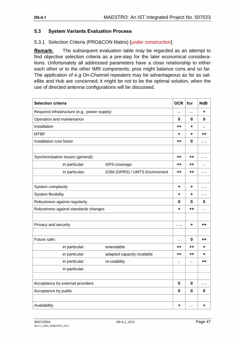
5.3 System Variants Evaluation Process
5.3.1 Selection Criteria (PRO&CON Matrix) [under construction]
Remark: The subsequent evaluation table may be regarded as an attempt to find objective selection criteria as a pre-step for the later economical considera-tions. Unfortunately all addressed parameters have a close relationship to either each other or to the other IMR components; pros might balance cons and so far. The application of e.g On-Channel repeaters may be advantageous as far as sat-ellite and Hub are concerned; it might be not to be the optimal solution, when the use of directed antenna configurations will be discussed.
Selection criteria OCR fcv NdB
Required infrastructure (e.g., power supply) +
Operation and maintenance 0 0 0
Installation ++ +
MTBF + + ++
Installation cost factor ++ 0
Synchronisation issues (general): ++ ++
in particular: GPS-coverage ++ ++
In particular; GSM (GPRS) / UMTS Environment ++ ++
System complexity + +
System flexibility + +
Robustness against regularity 0 0 0
Robustness against standards changes + ++
Privacy and security + ++
Future safe: 0 ++
in particular: extendable ++ ++ +
in particular: adapted capacity /scalable ++ ++ +
in particular: re-usability ++
in particular:
Acceptance by external providers 0 0
Acceptance by public 0 0 0
Availability + +

D6-4.1 MAESTRO: An IST Integrated Project No. 507023
30/07/2004 D6-4.1_V3.0 Page 48 D6-4.1_ASEL_MAESTRO_V3.0
Possible adaptation development effort ++ 0
OCN = On-Channel Repeater = extremely unfavour-able
FCV = Frequency Covnertion Repeater = unfavourable
NdB = NodeB based Repeater 0 = neither nor
+ = advantageous
++ = very advantageous
Efficiency (based on individually tailored concepts)
Adaptation development effort
Availability Of Suitable Equipment
Satellite (Features, Equipment
Repeaters
Antennas
RNC / NodeB network
Synchronisation extension
Communication Environment

D6-4.1 MAESTRO: An IST Integrated Project No. 507023
30/07/2004 D6-4.1_V3.0 Page 49 D6-4.1_ASEL_MAESTRO_V3.0
6 ANNEX 1 – DEDICATED INVESTIGATION RESULTS
6.1 Synchronisation Issue Studies Between HUB And IMR
6.1.1 Usage Of UMTS Repeaters For Synchronisation
It is obvious that applying a NodeB to the IMR-branch and, additionally, to use it for shared traffic causes higher-than-average problems. It is not clear yet, whether this solution will increase cost and effort (instead decrease those ones). It is also not clear from the technical point of view, whether the co-use of the supplying en-vironment of an established NodeB compared with stand-alone repeater solutions will be advantageous.
(a) Summary On Existing Procedures In any case (option 1 or option 2) the SFNs of both NodeBs are not synchronous. This is the main difference to the synchronisation of radio links in the soft hand-over situation, where corresponding CFNs are equal. As the terminal does not see the frame numbers, it is the RNC which could recalculate the appropriate BFN/SFN for the 2nd NodeB, so that the content is delivered time-synchronous over different SFNs of the two NodeB's S-CCPCH.
Furthermore the application of the existing procedures would require for the UE to provide a greater window for the processing of the two signals.
(b) UMTS Repeaters The simplest solution would be to apply real UMTS-repeaters instead of the "ter-restrial repeater-" NodeBs. Repeaters would provide in general a slight delay of the signal (less than 6us according product information), which could be helpful to select the better signal and to reduce interference.
If the Repeaters are used inside buildings only, the repeaters could send on the same frequency as the "satellite" NodeB.
If the repeaters are used in urban regions, the "satellite" NodeB has also to be simulated by a repeater and all repeaters have to use the same sending fre-quency, which should be different from the frequency, which is provided by the "source NodeB". Repeaters sending on the same frequency as the received sig-nal, would also receive and amplify their own signal. In this case the signals of the source NodeB would not be received by the terminal. Attenuation can only be achieved by suitable antenna configurations.
(c) Impact On The Final System Repeaters would be a good solution for the final satellite system. The UMTS signal could be split in a direct and an indirect (for the repeaters) link either by the Hub NodeB, the Satellite transmitter or even by the satellite. The satellite sends the UMTS wave form signal directly and over the 12MHz band to the repeaters, which convert it to the frequency of the direct link .

D6-4.1 MAESTRO: An IST Integrated Project No. 507023
30/07/2004 D6-4.1_V3.0 Page 50 D6-4.1_ASEL_MAESTRO_V3.0
Further on there is no need in sharing terrestrial NodeB's capacity between their RNC and the Hub RNC. This sharing would cost a considerable capacity of the NodeB, especially because it requires the down-link. Additionally it is difficult to use the SDMB reserved frequencies, if an UMTS operator uses only the lower bands of terrestrial UMTS (linearity of amplifier). It is also a question, whether we have UMTS NodeBs exactly in those locations, where we have no line-of-sight to the satellite. Repeaters at these locations would be quite cheaper than NodeBs.
To be continued
6.1.2 Usage Of NodeB For Synchronisation
Synchronisation of and by means NodeBs aims at the achievement of common timing references among different nodes. Though normally not required, for some specific applications (like IMR inter-working / inter-operation) such synchronisation may be helpful and necessary.
In order to avoid buffer-times and thus speeding up the transmission delay, it could be suitable to estimate the timing differences between RNC and NodeB without the need to compensate the phase differences within the NodeB´s internal count-ers. This is the reason why UTRAN provides three synchronisation mechanisms over Iub:
synchronisation between the RNC and its NodeBs;
synchronisation of NodeBs among each other;
frame synchronisation.
The synchronisation between the RNC and its NodeBs is shown in Figure 17. The Round Trip Delay (RTD) is calculated [3GP1]:
RTD = T2 ... T1 and T4 ... T3 where:
T1 RNC specific frame number (REN) that indicates the time when RNC sends the down-link Node Synchronisation control frame through the SAP to the transport layer.
T2 NodeB specific frame number (BFN) that indicates the time when NodeB receives the correspondent down-link Node Synchroni-sation control frame through the SAP from the transport layer.

D6-4.1 MAESTRO: An IST Integrated Project No. 507023
30/07/2004 D6-4.1_V3.0 Page 51 D6-4.1_ASEL_MAESTRO_V3.0
T3 NodeB specific frame number (BFN) that indicates the time when NodeB sends the up-link Node Synchronisation control frame through the SAP to the transport layer.
T4 RNC specific frame number (RFN) that indicates the time when the RNC receives the up-link Node Synchronisation control frame.
Each T1, T2 and T3 covers a range between 0 – 40,959.875ms with a step size of 0.125ms; T4 is not standardised yet.
The Node Synchronisation between the RNC and NodeB can be used to detect differing timing references between the UTRAN nodes (RFN in RNC and BFN in NodeB); in particular, synchronisation is required for the transport channels be-tween RNC and their connected Nodes both for determination of up-link and down-link offset values.
Measured values of timing relationships between those nodes are gained by the RNC-NodeB Synchronisation Procedure. This procedure is defined in the user plane protocols for Iub (DCH, DSCH, and FACH/PCH) and Iur (DCH).
When used from RNC over the DCH user plane, this procedure also allows to de-tect the actual round-trip-delay, as the Node Sync Control Frames are transferred the same way as the DCH frames).
The procedure may also be carried out over a high priority transport bearer. Meas-urements of node offsets can be made at start or restart as well as during normal operation to supervise the stability of the nodes.
Though an accurate Reference Timing Signal is used, there still might remain a low frequency deviation between the nodes.
If no accurate Reference Timing Signal is available, the local node reference os-cillator must be relied upon. In such cases the RNC-NodeB Node Synchronisation procedure can be used as a background process for detecting the frequency de-viation between the nodes.

D6-4.1 MAESTRO: An IST Integrated Project No. 507023
30/07/2004 D6-4.1_V3.0 Page 52 D6-4.1_ASEL_MAESTRO_V3.0
SRNC
Node B
BFN
RFN1 2 3 44094 4095 0
149 150 151 152 153147 148
Down-link Node Synchronization
[T1=40941.250]
Up-link Node Synchronization
[T1=40941.250, T2=1492.500, T3=1505.000]
T1
T2 T3
These two paths (T1...T2 and T3...T4) perform together the Round Trip Delay(RTD)
T4
Figure 17: RNC-NodeB synchronisation
In the RNC-NodeB Node Synchronisation procedure, the RNC sends a down-link Node Synchronisation control frame to NodeB containing the parameter T1. Upon reception of a down-link Synchronisation Control Frame, the NodeB shall respond with up-link Synchronisation Control Frame, indicating T2 and T3, as well as T1 which was indicated in the initiating down-link NodeB Synchronisation Control Frame (Figure 17).
In order to monitor the TOA when no down-link data frames are sent, a synchroni-sation procedure is defined in the Iub/Iur frame protocols ([4],[5]). This procedure makes use of up-link and down-link Synchronisation Control Frames (see Figure 18).
The SRNC sends down-link Sync Control frame containing the CFN in which the control frame should be received by the NodeB. When the NodeB receives the down-link Synchronisation Control Frame (SCF), it always replies with an up-link Synchronisation Control Frame containing the TOA, even if the down-link Control Frame is received within the receiving window as shown in Figure 18.
SRNC
Node B
CFN
CFN150 151 152 153147 148 149
149 150 151 152 153147 148
Down-link Synchronization[CFN = 151] Up-link Synchronization
[TOA = 5.750ms]
Receiving Window
TOA

D6-4.1 MAESTRO: An IST Integrated Project No. 507023
30/07/2004 D6-4.1_V3.0 Page 53 D6-4.1_ASEL_MAESTRO_V3.0
SRNC
Node B
CFN
CFN150 151 152 153147 148 149
149 150 151 152 153147 148
Down-link Synchronization[CFN =150] Up-link Synchronization
[TOA = 5.250ms]
Receiving window
TOA
Figure 18: TOA monitoring
TOA-monitoring is executed through Frame Protocol Synchronisation procedure (TOA >0, TOA <0 as shown in Figure 18.
6.1.3 Features Provided In UMTS For Timing Adjustment
The channels used for SDMB are shown in Figure 19.
S-CCPCH Physical Channels
Transport Channels
PHY
MAC
Logical Channels
FACH
CTCH
P-CCPCH
BCH
BCCH
SCH CPICH
Common Traffic CH.
Forward Access CH.
Secondary Common Control Physical CH.
Primary Common Control Physical CH.
Broadcast Control CH.
Broadcast CH.
Synchronisation CH.
Common PIlot CH.
PICH
Paging Indication CH.
optional
Figure 19: Channels used in SDMB
The Secondary Common Control Physical CHannel (S-CCPCH) is the only com-mon physical channel that can be aligned on a multiple of 256 chips, as shown in Figure 20 The other common physical channels are aligned on the 10ms frame structure.
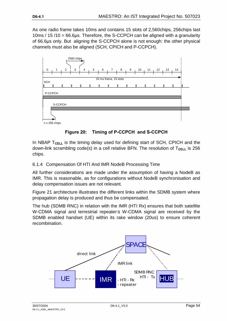
D6-4.1 MAESTRO: An IST Integrated Project No. 507023
30/07/2004 D6-4.1_V3.0 Page 54 D6-4.1_ASEL_MAESTRO_V3.0
As one radio frame takes 10ms and contains 15 slots of 2,560chips, 256chips last 10ms / 15 /10 = 66.6µs. Therefore, the S-CCPCH can be aligned with a granularity of 66.6µs only. But aligning the S-CCPCH alone is not enough: the other physical channels must also be aligned (SCH, CPICH and P-CCPCH).
0 1 3 4 5 6 7 8 9 10 11 12 14 2 13
10 ms frame, 15 slots
2560 chips
P-CCPCH
S-CCPCH
n x 256 chips
SCH
Figure 20: Timing of P-CCPCH and S-CCPCH
In NBAP TCELL is the timing delay used for defining start of SCH, CPICH and the down-link scrambling code(s) in a cell relative BFN. The resolution of TCELL is 256 chips.
6.1.4 Compensation Of HTI And IMR NodeB Processing Time
All further considerations are made under the assumption of having a NodeB as IMR. This is reasonable, as for configurations without NodeB synchronisation and delay compensation issues are not relevant.
Figure 21 architecture illustrates the different links within the SDMB system where propagation delay is produced and thus be compensated.
The hub (SDMB RNC) in relation with the IMR (HTI Rx) ensures that both satellite W-CDMA signal and terrestrial repeater’s W-CDMA signal are received by the SDMB enabled handset (UE) within its rake window (20us) to ensure coherent recombination.
UE IMR HUB
SPACEdirect link
IMR link
- HTI - Rx- repeater
HTI - TxSDMB RNC

D6-4.1 MAESTRO: An IST Integrated Project No. 507023
30/07/2004 D6-4.1_V3.0 Page 55 D6-4.1_ASEL_MAESTRO_V3.0
Figure 21: Direct link and IMR link
The SDMB RNC shall delay the information/signal transmitted by the SDMB No-deB to take into account the maximum processing time of the HTI Tx + HTI Rx + ‘enabled S-DMB’ NodeB (repeater), illustrated in Figure 21.
The HTI Rx will synchronise the information/signal transmitted by the ‘enabled SDMB’ NodeB to achieve time alignment between both signals from the satellite and from the terrestrial repeater at the UE side. For that, a cache memory is needed to absorb the worst case time difference [500ms].
The use of a common clock reference in the hub and in the IMR is required to ad-just the IMR’s nodeB modem time reference with regards to time reference sent by the HTI Tx/SDMB RNC.
6.1.5 Alignment Of The Satellite And IMR Signals
(a) Synchronisation Considerations:
The synchronisation issues may be fairly solved by applying a GPS receiver to the NodeBs. This synchronisation is intended to control both clock frequency and phase. Unfortunately this synchronisation mechanism, as described in [3GP1], section 6.1.2.1, is intended only for TDD mode and cannot applied here one-to-one.
The Alcatel NodeB V2 used in MAESTRO, however, is already equipped with add-on synchronisation ports but the software does not handle it yet. One solution could be an upgrading adaptation development of the NodeB software.
The RNC should itself be synchronised, too, e.g., by implementing a procedure to loop-back the NodeB´s GPS-synchronised clock - see [3GP5] section 5.2.9, used for LCS - Location Services - described in [3GP6]
Additionally, the standard UMTS granularity to adjust the timings is not sufficient: it is of 66µs only, and the UE rake receiver accepts 20 µs maximum. Therefore, the 3GPP specifications should be upgraded to enable time adjustments with a granu-larity below 66µs.
For a given frame, the BFN (NodeB frame number) in the Hub NodeB and the BFN in the IMR NodeB must be equal (the BFN is used to transmit the SFN to the UEs). The BFN depends on each NodeB start-up time, and cannot be controlled; therefore, the BFN in the Hub and in the IMR will be different. One solution could be to upgrade the 3GPP specifications and thus enabling BFN setting through the Iub.
(b) Distance Considerations (direct link vs IMR link):
In addition to the compensation of HTI and IMR NodeB processing time described in the previous section, which is performed at frame level, the signal coming di-rectly from the satellite must be aligned with precision with the signal coming through the IMR.

D6-4.1 MAESTRO: An IST Integrated Project No. 507023
30/07/2004 D6-4.1_V3.0 Page 56 D6-4.1_ASEL_MAESTRO_V3.0
As shown in, Figure 22 the geo stationary satellite being at dd = 36,000km from the earth, it can be estimate that:
di1 - dd < di2;
di1 - dd induces a fixed reception delay (or advance) D1, of maximum 10 / 300,000 = 33µs, if di2 = 10km.
D1 is constant and depends on the location of the IMR relatively to its sat-ellite.
UE IMR
SPACE
direct link
IMR link
dd
di1
di2
Figure 22: Distances through direct link and IMR link
In addition, a variable delay D2 is provoked by the distance between the UE and the IMR. The reception of two identical signals with a time difference more than the rake window duration (20us) causes interference and then degrades the re-ception performance. Considering that the rake receiver in the UE can recombine signals received with a time difference of up to 20 µs, the IMR transmission power should be limited to cover a maximum distance.
The approximate cell size can be calculated by:
DRake = 20 µs x 300,000km/s = 6km.
DRake seems compatible with the fact that the IMRs will be installed in dense ur-ban areas, where the goal is not to cover a very large cell.
(c) Distance Considerations (between north and south beam limits):
This briefly explained issue is only relevant for a synchronised IMR application. In this concept the RNCs and NodeBs together with the GPS cater for bit- and frame synchronism and additional artificial frame content delays. This fact requires a fully synchronised network of RNCs and NodeBs, i.e., a time delayed satellite beam meets a fully synchronised network. Depending on the actual delay time – as cal-culated below – the propagation delay time of the beam may fit into those time constraints or not.As these different propagation delay is a physical phenomena and can only be adjusted (in the hub) once for the whole system no additional bal-ance can be applied.
It is now subject of the subsequent considerations to find out whether propagation delay variants will support/skip the synchronous system concept.

D6-4.1 MAESTRO: An IST Integrated Project No. 507023
30/07/2004 D6-4.1_V3.0 Page 57 D6-4.1_ASEL_MAESTRO_V3.0
Simplified Model By Neglecting The Longitude:
In order to give a first overview on the delay problem an initial simplification is ap-plied. The restriction is made by calculating only in a two dimensional sphere which might be sufficient for the first batch. Depending on the outcome results a three-dimensional calculation can be added, if necessary. Subsequent Figure 23 gives a view on the relevant parameters and distances.
The satellite SAT is assumed to be positioned in orbit on the equatorial line in a distance D of 36,000km. Its Cartesian co-ordinates are [xSAT 0]. The earth ra-dius R is assumed to 6,366km.
The satellite´s beam covers an latitude area between 35 (1)and 65 (2) degrees north represented by the Surface Points SF1 and SF2 with its co-ordinates [x1y1] and [x2y2]. Caused by the deflection of the earth surface the distances between satellite and SF1 (d1) differ to that between satellite and SF2 (d2).
It is now matter of this investigation to prove that all UEs on the curve between SF1 and SF2 receive the broadcast data stream within the Rake´s tolerance frame of about 20us. Increasing this value would mean that the UEs cannot combine the received signals; they will be regarded as non-correlated signals.
The simplification is made by neglecting the longitudinal angles 10 to 30 degrees and thus not calculating in a three-dimensional space.
x2
x1
y1
y2
SF1
SF2
2
1
SAT
xSATySAT x
y
d1
d2
Equator
R D
Earth
Figure 23: Propagation delay variants
Assumptions And Calculations:
Earth radius R = 6,366km
Satellite distance D = 36,000km Latitude 1 = 35o
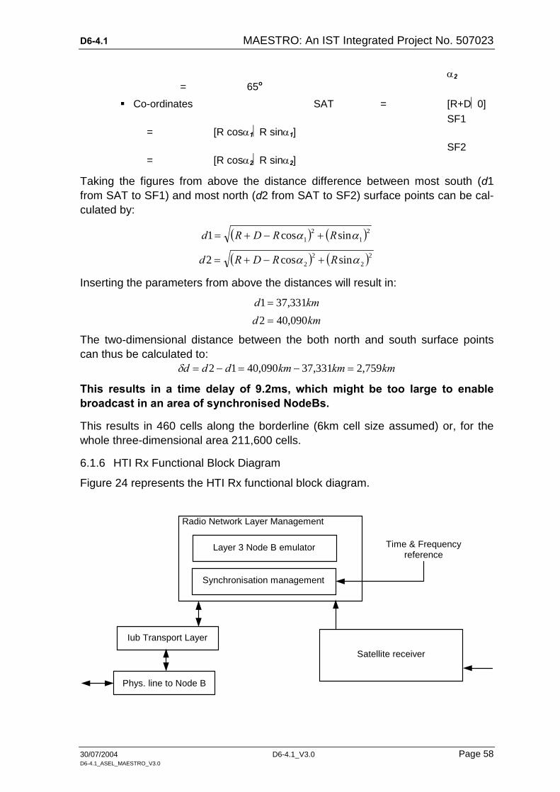
D6-4.1 MAESTRO: An IST Integrated Project No. 507023
30/07/2004 D6-4.1_V3.0 Page 58 D6-4.1_ASEL_MAESTRO_V3.0
2 = 65o
Co-ordinates SAT = [R+D0]
SF1 = [R cos1R sin1]
SF2 = [R cos2R sin2]
Taking the figures from above the distance difference between most south (d1 from SAT to SF1) and most north (d2 from SAT to SF2) surface points can be cal-culated by:
212
1 sincos1 RRDRd
222
2 sincos2 RRDRd
Inserting the parameters from above the distances will result in:
kmd 331,371
kmd 090,402
The two-dimensional distance between the both north and south surface points can thus be calculated to:
kmkmkmddd 759,2331,37090,4012
This results in a time delay of 9.2ms, which might be too large to enable broadcast in an area of synchronised NodeBs.
This results in 460 cells along the borderline (6km cell size assumed) or, for the whole three-dimensional area 211,600 cells.
6.1.6 HTI Rx Functional Block Diagram
Figure 24 represents the HTI Rx functional block diagram.
Radio Network Layer Management
Iub Transport Layer
Synchronisation management
Phys. line to Node B
Satellite receiver
Layer 3 Node B emulator Time & Frequency reference

D6-4.1 MAESTRO: An IST Integrated Project No. 507023
30/07/2004 D6-4.1_V3.0 Page 59 D6-4.1_ASEL_MAESTRO_V3.0
Figure 24: HTI Rx functional block diagram
6.1.7 Conclusions

D6-4.1 MAESTRO: An IST Integrated Project No. 507023
30/07/2004 D6-4.1_V3.0 Page 60 D6-4.1_ASEL_MAESTRO_V3.0
6.2 NodeB-Iub And Uu Synchronisation Considerations
6.2.1 Issue Description
If the concept considerations lead to the application of a NodeB in the terrestrial repeater branch, then significant synchronisation problems will emerge; synchroni-sation problems between the Hub-NodeB ("satellite NodeB") and the potentially co-sited repeater NodeB. ("terrestrial NodeB"). Still more, the UMTS standard does not provide synchronisation rules and applications for absolute synchronisa-tion in FDD.
The situation will grow worse when the "terrestrial" NodeB has to be shared with a private provider, who may not like to be touched by specific MAESTRO require-ments and potential QoS issues.
Taking into account the standard Iub/NBAP procedures for common channels, the only achievable synchronisation can be gained on frame level which may not be sufficient. The NodeB uses the frame number received from the RNC to transmit the data block at the indicated time (1 frame = 10ms).
To achieve a synchronisation on chip or bit level, a radio interface sync-procedure is required similar to the one defined for dedicated channels and soft handover feature. Though not standardised, a similar procedure for common channels should be implemented for SDMB. The synchronisation mechanisms used for the Alcatel NodeB are compliant to the 3GPP specifications, as far as they exist.
6.2.2 Node Synchronisation
The Node synchronisation procedure is used to get a timing reference of the No-deB in the C-RNC. Node Synchronisation relates to the estimation and com-pensation of timing differences among UTRAN nodes. The procedure is as fol-lows:
The CRNC sends a down-link Node Synchronisation Control Frame to the NodeB reporting an RNC frame number when it was sent.
The NodeB replies with an up-link Node Synchronisation Frame, in-dicating a NodeB frame number at the reception of the down-link frame, and another frame number at sending back the up-link frame.
This procedure is supported on the specific high priority VC on which only one AAL2 connection is established for this purpose.
Here only the "RNC - NodeB" Node-synchronisation is considered. This Node syn-chronisation allows to get knowledge of the timing differences between RNC and its NodeBs, and thus to estimate the phase difference between RFN and BFN of these nodes. The estimated phase difference is used in the down-link data trans-mission (i.e., Tx direction) in order to minimise the transmission delay and the buffering time.
For the Alcatel NodeB this procedure is performed at NodeB restart, and periodi-cally (e.g. once a day) after that.
D6-4.1 MAESTRO: An IST Integrated Project No. 507023
30/07/2004 D6-4.1_V3.0 Page 61 D6-4.1_ASEL_MAESTRO_V3.0
6.2.3 Network Synchronisation
(a) General
Network Synchronisation relates to the distribution of synchronisation references to the UTRAN Nodes and the stability of the clocks in the UTRAN (and perform-ance requirements on UTRAN internal interfaces).
The distribution of an accurate frequency reference to the network elements in the UTRAN is related to the main issue to provide a synchronisation reference with a frequency accuracy better than 0.05 ppm at the NodeB in order to properly gener-ate signals on the radio interface.
For the time being this synchronisation is achieved for the Alcatel NodeB by syn-chronisation to the (ATM) transport network.
(b) Synchronisation Under Normal Conditions
If the transmission network can provide the required frequency accuracy, the No-deB V2 is synchronised on it. In case of e.g. an ATM network unable to provide this accuracy, the NodeB will switch to the free run mode.
Normally the NodeB is basically synchronised on the transmission network, if the network can provide the required frequency accuracy (in normal conditions better than 0.05 ppm). The NodeB´s local oscillator permanently monitors the quality of the clock delivered by the network. For the case of a loss of incoming signal or if a clock drift is detected, the NodeB then switches to its local clock mode. After the fault has disappeared the NodeB will switch back to the transmission line synchro-nisation source.
When the Iub is supported on several E1 links, the NodeB performs its synchroni-sation on the first E1, and in case of failure of this E1, it switches to the second one and so on.
The Alcatel NodeB V2 clock is compliant with 3GPP TS 25.104 (0.05 ppm) [3GP5]. The NodeB synchronises:
on Iub link when the clock delivered by this link is of good quality,
on the OCXO (Oven Controlled Oscillator) when the clock delivered by the Iub link has bad quality.
Future option: on an external GPS clock, as the NodeB architecture allows to synchronise the OCXO via an external GPS clock.
6.2.4 Down-Link Transport Channel Synchronisation
The Transport Channel Synchronisation mechanism defines synchronisation of the frame transport between RNC and NodeB, considering radio interface timing.
This procedure is used by CRNC to adjust the transmission time for data frames on FACH and PCH FP. The C-RNC sends a down-link Synchronisation Control

D6-4.1 MAESTRO: An IST Integrated Project No. 507023
30/07/2004 D6-4.1_V3.0 Page 62 D6-4.1_ASEL_MAESTRO_V3.0
Frame indicating the target CFN value. The NodeB replies with an up-link Syn-chronisation Frame indicating the ToA for the down-link frame, and the CFN value received in the down-link frame.
6.2.5 Down-Link Timing Adjustment
The Time Alignment Handling procedure over Iu relates to the control of the down-link transmission timing in the CN nodes in order to minimise the buffer delay in SRNC. This procedure is controlled by SRNC.
This procedure is used by the NodeB to report to the CRNC an incorrect arrival time of a down-link data frame in the NodeB. It is initiated by the NodeB when a down-link frame arrives outside of the defined arrival window.
k:th S-CCPCH
AICH access slots
Secondary SCH
Primary SCH
S-CCPCH,k
10 ms
PICH
#0 #1 #2 #3 #14 #13 #12 #11 #10 #9 #8 #7 #6 #5 #4
Radio frame with (SFN modulo 2) = 0 Radio frame with (SFN modulo 2) = 1
DPCH,n
P-CCPCH
Any CPICH
PICH for k:th S-CCPCH
Any PDSCH
n:th DPCH
10 ms
Figure 25: Down-link physical channels - radio frame timing and access slot timing
6.2.6 MAESTRO Synchronisation Requirements
The SCCPCHs bearing the broadcast FACHs of the different NodeBs should be synchronised, i.e., the FACH of the "terrestrial NodeB"s should be started syn-chronously with the FACH of the "satellite- NodeB".
The terminal should see the FACH channels like ordinary dedicated channels be-ing in a macro diversity (softer handover situation). This is necessary, if the termi-nal has to synchronise signals in its rake window of 80 chips (20µs).

D6-4.1 MAESTRO: An IST Integrated Project No. 507023
30/07/2004 D6-4.1_V3.0 Page 63 D6-4.1_ASEL_MAESTRO_V3.0
Subsequent Figure 25 was taken from 3GPP TS 25.211 and describes summaris-ing the timing relationships between the down-link channels of one NodeB as re-quired for the MAESTRO concept.
6.2.7 Radio Interface Synchronisation (Uu)
The radio Interface synchronisation relates to the timing of the radio frame trans-mission in down-link [FDD]. In FDD Radio Interface synchronisation is necessary to assure that the terminal receives radio frames synchronously from different cells, in order to minimise terminal buffers.
6.2.8 Conclusions:

D6-4.1 MAESTRO: An IST Integrated Project No. 507023
30/07/2004 D6-4.1_V3.0 Page 64 D6-4.1_ASEL_MAESTRO_V3.0
6.3 Standard Synchronisation Procedures In Detail
6.3.1 Parameters And Functionality
The subsequent Figure 26 gives a view over the radio interface timing synchroni-sation details:
OFF +Tm = (SFN2 -DPCHnom) mod 256 frames
To
1
Rounded (Frame_offset + Chip_offset)
0
Tp2
t
Tp1
1st received DL DPCH finger relative DL DPCHnom
BFN Node B Frame Number (counter)CFN Connection Frame Number (DPCH related)DPCH Dedicated Physical Channel (CFN related)HO HandoverNBx Node B (x: 1=source, 2=target)OFF Offset with a range from 0 to 255 framesRFN RNC Frame Number (counter)RNC Radio Network ControllerSFN System Frame Number (counter)
Tcell Specifies the SFN delay relative BFNTm Measured by UE at HO, Tm has a range
from 0 to 38399 chips.To Is a constant of 1024 chips, is the nominal
difference between first received DPCH finger(DL DPCHnom) and TUETx at UE.
TpX Propagation delay (one way), UE to Cell XTUETx The time when UE transmits an
UL Dedicated Physical Channel.
Ex: OFF +Tm = 3.3300 frames OFF =3, Tm=12672 chips.
Tcell
Rounded (Frame_offset+Chip_offset)
DL BFN1 4094 4095 0 1 2 3 4SFN is delayed Tcell relative BFN
DL DPCH1 (CFN) 252 253 254 255 0 1 2DL DPCH1 = (SFN1 - Rounded (Frame_offset +
Chip_offset)) mod 256 frames
Ex: Frame_offset =2, Chip_offset =10240 chips
NB1
UE
DL DPCH1 252 253 254 255 0 1 2
UL DPCH (TUETx) 252 253 254 255 0 1 2
To +/-
DL DPCHnom(TUETx –To) 252 253 254 255 0 1 2
DL SFN2 4095 0 2 3 4 5
DL SFN2 (Cell 2) 4095 0 1 2 3 4 5
NB2 DL DPCH2 (CFN) 252 253 254 255 0 1 2
Ex: Chip_offset =12672 gives 128 chipsrounding error (12800 –12672).
UL DPCH2 252 253 254 255 0 1 2
UL DPCH2 relative DL DPCH2 at NB2 is delayed T0 +/- +2Tp2
DL DPCH2 252 254 255 1 2Due to: Rounding, time dispersion,
frequency drift and moving UE.
DL DPCHnom (TUETx -To) used as ref. at UE.
DL SFN2 is delayed Tp2 from NB at UE
DL SFN1 mod 256frames
254 255 0 1 2 3 4
DL SFN1 (Cell 1) 4094 4095 0 1 2 3 4
Tm
253
DL DPCH2 (CFN) =(SFN2 -Rounded (Frame_offset + Chip_offset) ) mod 256 frames
Figure 26: FDD Radio interface synchronisation timing diagram
The kth S-CCPCH has a timing offset of Tk * 256chips in relation to the P_CCPCH, where Tk is an integer of {0, 1, ..., 149} and may differ for different S_CCPCHs. The offset is set by the Common_Transport_Channel_set-up with the parameter SCCPCH_Offset.
The offset for a cell (in magnitudes of 256chips) in relation to the NodeB frame number BFN is defined in the parameter T_Cell of the Cell_set-up procedure (3GPP 25.402). Thus the offset of a S-CCPCH in relation to the BFN is (T_Cell + SCCPCH_Offset) * 256 (chips) or (T_Cell + SCCPCH_Offset) * 66,7us.
If the difference between both SFNs can be measured, synchronisation of the S_CCPCH of the second (terrestrial ) NodeB is possible by calculating the right

D6-4.1 MAESTRO: An IST Integrated Project No. 507023
30/07/2004 D6-4.1_V3.0 Page 65 D6-4.1_ASEL_MAESTRO_V3.0
T_Cell parameter for the Cell_set-up and the right SCCPCH Offset parameter for the S_CCPCH-set-up.
For the synchronisation of dedicated channels a procedure is described in 3GPP TS 25 402 chapter 8. This procedure is based on the measurements of the termi-nal on the time difference between its DPCH and its SFN, which is calculated by the RNC in terms of Frame Offset and Chip Offset and communicated to the No-deB.
In MAESTRO´s case there is no up-link from the terminal to the RNC. In addition, the interest is in synchronising the common channel. For this we require the time difference between the SFN and the S_CCPCH (which is the SCCPCH_Offset value from the S_CCPCH set-up). From the Node synchronisation the RNC knows the BFN of both NodeBs and also the phase difference of both NodeBs since No-deB restart.
On the basis of the existing capabilities of the NodeB there are two approaches to set up a S_CCPCH on a second NodeB, which is nearly synchronous to the S_CCPCH of the first NodeB. Nevertheless, the NodeB synchronisation is not suf-ficient for the MAESTRO application, neither for option 1 (on Iub link) nor 0ption 2 (on the OCXO).
6.3.2 Using NodeB - RNC Synchronisation
Based on the knowledge of the phase differences PD:
BFN = [RFN + PD] modulo 4096 between both NodeBs, it is possible to map the BFN of one cell on a BFN of the other cell:
BFNTer = [BFNSat + PDTer - PDSat ] modulo 4096. It is also possible to do the same calculation for the SFNs:
SFNTer = SFNSat + [PDTer - PDSat - TCellSat + TCellTer ] modulo 256
Please note, that in both cases the calculations are simplified; they do not take into account, that the phase differences do not represent whole frames, but also off-sets, which normally are discarded by rounding. This can be used to calculate the SCCPCH_Offset.
This approach can only be applied, when the NodeBs are controlled by the same RNC. As basis for calculation of the phase difference, the BFN and the RFN at sending / response time are taken. The quality of the measurements depends also on the delays of the used ATM network. The granularity of the measured time is given in ms with 125us-steps. This is twice as much as the granularity of the SCCPCH_Offset between two S_CCPCH channels. If the two S_CCPCHs would be synchronised using this information, the terminal must provide a rake window of about 125us.

D6-4.1 MAESTRO: An IST Integrated Project No. 507023
30/07/2004 D6-4.1_V3.0 Page 66 D6-4.1_ASEL_MAESTRO_V3.0
6.3.3 Conclusions
D6-4.1 MAESTRO: An IST Integrated Project No. 507023
30/07/2004 D6-4.1_V3.0 Page 67 D6-4.1_ASEL_MAESTRO_V3.0
6.4 Synchronisation Based On GPS
6.4.1 GPS Application On The SDMB Core System
The synchronisation of the Hub NodeB (NodeB/1) becomes mandatory for the case that the IMR´s core will consist of a NodeB (NodeB/2), independent whether this Node will be shared by a private user. This synchronisation could be done by synchronisation to the same transport network. Formerly initial consideration were made for this problem but restricted to a test-bed application only, where the No-deB/2 played the role of a satellite emulator.
The actual problem for the MAESTRO application is now the supplementary syn-chronisation of the NodeB/1 (Hub NodeB) in the Hub branch and, additionally, the extreme precise handling of the required propagation delay balance of the Iub and Uu data streams.
For the case that no significant attempt is planned and made to enhance the cur-rent functionality of the NodeB and the surrounding network, the GPS alternative seems to be suitable for the first to tackle the most exigent synchronisation issues. Synchronisation by GPS means on Iub-side bit-synchronisation and frame (-begin) synchronisation.
6.4.2 GPS Receiver Connection To The NodeB
The NodeB´s Connection Area (CA) provides remote access to the Station Unit´s (SUMU) external interface and thus the later connection of an optional GPS re-ceiver module. This module delivers the time and position data which is used for alarm and performance measurement time stamping, OCXO clock and frame number synchronisation.
The GPS receiver itself has no own BCB terminal but it can be connected to the SUMU´s BCB terminal. It provides an EEPROM where RI data is stored. The GPS receiver has a RS232 link line for message exchange purposes. This feature is not yet part of the commercial product.
The Alcatel GPS receiver consists of two parts, a proprietary printed board to con-nect the GPS receiver to the SUMU module and the GPS receiver itself, a com-mercial product from Trimble (Lassen SK II) and Wharton. The Wharton 488GPS receiver system is designed to allow 482 series master clocks to be automatically synchronised from the GPS satellite time transmissions
The Alcatel´s proprietary connection boards are available for MAESTRO and the existing receiver HW provides interfaces to deliver clock and absolute time.
6.4.3 The GPS Receiver Components
(a) Antenna Module The satellites transmit highly accurate, real time world-wide, navigation information at a frequency of 1,575.42MHz that anyone can receive and thus use to identify their position together with a precise local time.

D6-4.1 MAESTRO: An IST Integrated Project No. 507023
30/07/2004 D6-4.1_V3.0 Page 68 D6-4.1_ASEL_MAESTRO_V3.0
The active antenna module is a low-profile disc shaped unit, 10cm diameter and 3.5cm high, specifically designed for GPS use. GPS signals are received by the antenna, amplified within the antenna assembly and then relayed to the GPS re-ceiver for processing.
The antenna should be horizontally mounted with a clear view of 75% of the sky. If the sky view is reduced, the interval between ‘switch-on’ and system time syn-chronisation will be considerably increased.
The antenna module transmits the received GPS signals and receives power (5V DC @ 25mA) from the GPS receiver/decoder module via a single 6m RG58 coax-ial cable. A post mounting clamp is supplied to enable the antenna to be fixed to a suitable horizontal or vertical post of up to 2m diameter.
(b) GPS Receiver/Decoder Module
The GPS receiver/decoder module contains an advanced 6-Channel parallel re-ceiver, a power supply and a microprocessor based communications interface. This module should be mounted in a protected location within 6m of the antenna.
To ensure ease of operation and to remove the possibility of operator error the 488GPS system is designed to self initialise without the necessity of operator data input.
When the accurate satellite time information is available synchronising time sig-nals are transmitted every minute from the receiver/decoder module to the master clock using W482 time code. This code provides UTC time and date information and may be used to synchronise any 482 series master clock.
The 482 series master clock will automatically convert the UTC time to local time using operator pre-programmed time offset conditions. When the 482 master clock is synchronised with the GPS receiver/decoder module, all transmitter signals are accurate to within ± 1ms. Higher accuracy is available on request.
6.4.4 GPS-Clock Based Synchronisation Procedure
The introduction of the GPS into the MAESTRO system would increase the capa-bilities of the NodeB with a reasonable effort. This approach would synchronise both NodeBs on the same BFN. It has to be defined, how both NodeBs select (or are provided with) the same absolute time to start with BFN = 0:
The BFN is reset to 0 after 4096 * 10ms = 40,960s.
The absolute time sent by GPS is given in weeks and seconds of weeks after Jan 6th 1980. So a possible synchronisation would be, if the BFN counter is reset to 0, when GPS_time_in_seconds modulo 4096 (or 1024) equals 0.
The BFN could also be set to (GPS_time_in_seconds *100) modulo 4096.

D6-4.1 MAESTRO: An IST Integrated Project No. 507023
30/07/2004 D6-4.1_V3.0 Page 69 D6-4.1_ASEL_MAESTRO_V3.0
The roll-over period of the weeks can be neglected, because this again is 1024 and thus does not influence the calculation.
Furthermore mechanisms have to be defined, how a NodeB can syn-chronise after recovery. Essentially the same method to calculate a re-synchronisation time can be applied here.
It will still be a problem, that the recovery with GPS synchronisation means a longer NodeB outage than an un-synchronous recovery.
For the NodeB synchronisation a number of questions and open points still re-main:
How can the new BFN be assigned to the FPGAs (without disturbing the Telecom applications)?
The BFN should be assigned before telecom application are set up and before the connection to the RNC is established.
Can the use of the transport network clock or the use of the GPS clock provide better synchronisation?
What will happen, if for any reasons GPS is not available over some time ?
In contrary to the MoDis field trial the MAESTRO requires synchronisa-tion and re-synchronisation mechanism
Is it sufficient, if the clock is also synchronised via GPS.
The distance of about 1km (cell size) between two NodeBs should not cause a delay between the GPS signal reception at both NodeBs.
If one of these NodeB synchronisation methods is applied, the cells and SCCPCHs for both NodeBs have to be set-up with the same T_Cell and SCCPCH_FrameOffset values.
6.4.5 Identified State Of Realisation
HW, the GPS receiver Lassen SK II from trimble has been used for GSM. A board which can be used to connect the GPS receiver to the Station Unit (SUMU) is available.
SW to support GPS synchronisation is not yet implemented.
6.4.6 Identified Problems For The GPS Synchronisation
It is necessary to start the GPS receiver independently from the NodeB, because the GPS receiver needs about 15 minutes to calculate its posi-tion and the actual time from the GPS signals (the whole GPS informa-tion is transmitted in 12.5min. The GPS time in seconds is repeated every 6 seconds.). After this time the GPS time can be used to deduce the BFN for the NodeB.
D6-4.1 MAESTRO: An IST Integrated Project No. 507023
30/07/2004 D6-4.1_V3.0 Page 70 D6-4.1_ASEL_MAESTRO_V3.0
The modification of the BFN will generate a NodeB restart caused by the telecom application, if already active. Only for the purpose of the field trial, this should not be a problem.
When a NodeB has to be restarted in an already deployed network, there will be a delay of availability depending on the availability of the exact GPS time and the delay to start frame synchronisation with a new calculated BFN.
6.4.7 Required SW Implementations
Implement an interface (including alarm handling) to the GPS receiver.
Implement an algorithm for the definition of the BFN from the GPS time.
Implement a "GPS/nonGPS timing" selection mechanism and menu for the NEMB
Implement alarm handling for the new module.
Implement the BFN setting and clock deduction from the GPS receiver for the SUMU transmission HW (see suggestion above :to be set to (GPS_time_in_seconds *100) modulo 4096. )
Implement clock synchronisation from GPS clock.
The enhancements could not be implemented and tested in the development envi-ronments of the UMTS development centre. Separate development environments would have to be set-up for this purpose. The modification would concern different SW platforms of the NodeB including FPGA firmware and the Network Manage-ment Tools. Therefore it is unlikely to develop this feature within the MAESTRO timeframe.
6.4.8 Conclusions

D6-4.1 MAESTRO: An IST Integrated Project No. 507023
30/07/2004 D6-4.1_V3.0 Page 71 D6-4.1_ASEL_MAESTRO_V3.0
6.5 Shared NodeB Physical Issues
6.5.1 General Considerations
In order to install and operate the MAESTRO – System at a minimum of cost, it seems plausible to make use of nationally installed (e.g., NodeB) telecommunica-tion equipment; in particular, if it is under-utilised or, for expansion purposes, the rack only partly equipped and in use. It should be noted that in context of NodeB application as terrestrial repeater it makes only sense to share a NodeB with an-other network or service provider (in the following called owner). Pure stand alone NodeB solutions will fail because of its cost.
For all further considerations in this paragraph it is assumed that only Alcatel No-deB V2 base stations will be applied. This reduces the number of other potential candidates strictly. Furthermore, it is assumed, too, that commercial network providers have established an UMTS network with UMTS NodeBs, which do not operate at full capacity with both data traffic and physical expansion states. This means, Maestro might be cordially invited to share the base station and:
bring the equipment of its own (e.g., additional boards, SW extensions, etc.);
does not touch (i.e., modify) the equipment of the owner;
does not touch and influence sections operated by the owner;
modifies the base station only by add-ons.
The issues on physical level additionally emerging from the NodeB sharing phi-losophy can be grouped into 4 problem areas:
Uu-side antenna connection and antenna configuration;
Iub-side GPS bit and frame synchronisation;
Iub-side RNC response emulator;
Iub-side RNC-data multiplexer and/or timely control of different Iub data flows.
6.5.2 Shared NodeB RF Analogue Front End
(a) The RF-Front-End In Brief:
The subsequent Figure 27 depicts the radio part of a NodeB and is to facilitate a better understanding of the shared NodeBs Uu-side issues. The figure shows two radio modules capable of 2-antenna diversity operation. The boxes left hand side and right hand side accommodate the linearised power amplifier (PA), its control-ling feed-back and pre-distortion path, clipping, up-converter and transmission (Tx) filters.
The down-link path is capable to handle up to four UMTS frequency channels. They may be accommodated within any consecutive 20MHz sub-band of the overall 60MHz UMTS transmit frequency band. The antenna network (ANRU) module allows the connection of two transmitters in case of transmit diversity.
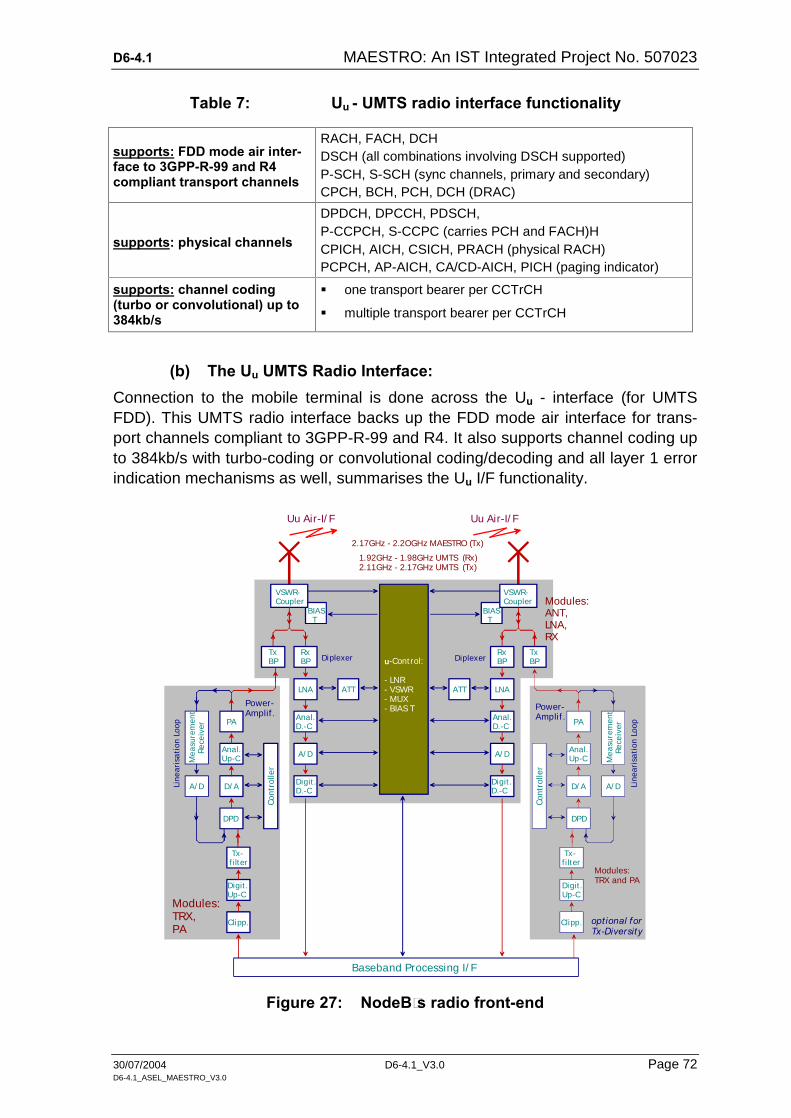
D6-4.1 MAESTRO: An IST Integrated Project No. 507023
30/07/2004 D6-4.1_V3.0 Page 72 D6-4.1_ASEL_MAESTRO_V3.0
Table 7: Uu - UMTS radio interface functionality
supports: FDD mode air inter-face to 3GPP-R-99 and R4 compliant transport channels
RACH, FACH, DCH DSCH (all combinations involving DSCH supported) P-SCH, S-SCH (sync channels, primary and secondary) CPCH, BCH, PCH, DCH (DRAC)
supports: physical channels
DPDCH, DPCCH, PDSCH, P-CCPCH, S-CCPC (carries PCH and FACH)H CPICH, AICH, CSICH, PRACH (physical RACH) PCPCH, AP-AICH, CA/CD-AICH, PICH (paging indicator)
supports: channel coding (turbo or convolutional) up to 384kb/s
one transport bearer per CCTrCH
multiple transport bearer per CCTrCH
(b) The Uu UMTS Radio Interface: Connection to the mobile terminal is done across the Uu - interface (for UMTS FDD). This UMTS radio interface backs up the FDD mode air interface for trans-port channels compliant to 3GPP-R-99 and R4. It also supports channel coding up to 384kb/s with turbo-coding or convolutional coding/decoding and all layer 1 error indication mechanisms as well, summarises the Uu I/F functionality.
Uu Air-I/ F
VSWR-Coupler
BIAS T
TxBP
RxBP Diplexer
LNA ATT
u-Control:
- LNR- VSWR- MUX- BIAS T
Anal.D.-C
A/ D
Digit .D.-C
Uu Air-I/ F
VSWR-Coupler
BIAS T
TxBP
RxBPDiplexer
LNAATT
Anal.D.-C
A/ D
Digit .D.-C
1.92GHz - 1.98GHz UMTS (Rx)2.11GHz - 2.17GHz UMTS (Tx)
PA
Anal.Up-C
D/ A A/ D
Me
asu
rem
ent
R
ece
iver
Con
trol
ler
Line
aris
ati
on L
oop
DPD
Digit .Up-C
Tx-f ilter
Clipp.
PA
Anal.Up-C
D/ AA/ D
Me
asu
rem
ent
R
ece
iver
Con
trol
ler
Line
aris
ati
on L
oop
DPD
Digit .Up-C
Tx-f i lter
Clipp.
Baseband Processing I/ F
opt ional forTx-Diversity
Modules:TRX,PA
Modules:TRX and PA
Modules:ANT, LNA,RX
Power-Amplif .
Power-Amplif .
2.17GHz - 2.2OGHz MAESTRO (Tx)
Figure 27: NodeB´s radio front-end

D6-4.1 MAESTRO: An IST Integrated Project No. 507023
30/07/2004 D6-4.1_V3.0 Page 73 D6-4.1_ASEL_MAESTRO_V3.0
(c) MAESTRO Uu Interface Add-On (1)
Sharing a NodeB commonly with a private network provider can be done in differ-ent ways. One of those is depicted in Figure 28 This way is only possible for the case that the base station does not operate at full capacity, in particular, when the racks and sub-racks are not fully equipped. Making use of sharing the Node means, for the first solution, to install a complete Tx-branch from the Base-band interface up to the antenna.
Uu Air-I/ F
VSWR-Coupler
TxBP
RxBP
Diplexer
PA
Anal.Up-C
D/ A A/ D
Me
asu
rem
ent
R
ece
iver
Con
trol
ler
Lin
eari
sati
on L
oop
DPD
Digit .Up-C
Tx-f i lter
Clipp.
Baseband Processing I/ F
Modules:TRX and PA
Power-Amplif .
Uu Air-I/ F
VSWR-Coupler
TxBP
Diplexer
2.17OGHz - 2.2OOGHz (MAESTRO Tx)
PA
Anal.Up-C
D/ A A/ D
Me
asu
rem
ent
R
ece
iver
Con
trol
ler
Lin
eari
sati
on L
oop
DPD
Digit .Up-C
Tx-f i lter
Clipp.
Modules:TRX and PA
Power-Amplif .
MAESTROExtension (1)
2.11OGHz - 2.17OGHz (private Tx)
Figure 28: MAESTRO add-on (1) for NodeB sharing

D6-4.1 MAESTRO: An IST Integrated Project No. 507023
30/07/2004 D6-4.1_V3.0 Page 74 D6-4.1_ASEL_MAESTRO_V3.0
Uu Air-I/ F
VSWR-Coupler
TxBP
RxBP
Diplexer
PA
Anal.Up-C
D/ A A/ D
Me
asu
rem
ent
R
ece
iver
Con
trol
ler
Lin
eari
sati
on L
oop
DPD
Digit .Up-C
Tx-f ilter
Clipp.
Baseband Processing I/ F
Modules:TRX and PA
Power-Amplif .
TxBP
Diplexer
2.17OGHz - 2.2OOGHz (MAESTRO Tx)
PA
Anal.Up-C
D/ A A/ D
Me
asu
rem
ent
R
ece
iver
Con
trol
ler
Lin
eari
sati
on L
oop
DPD
Digit .Up-C
Clipp.
Modules:TRX and PA
Power-Amplif .
MAESTROExtension
2.11OGHz - 2.17OGHz (private Tx)
Combiner,direct ional coupler
Tx-f ilter
Figure 29: MAESTRO add-on (2) for NodeB sharing
Caused by the slightly differing transmission frequency band (instead UMTS 2.11 – 2.17GHz now the MAESTRO 2.17 – 2.20GHz) some additional measures have to be taken (marked in by dark blue boxes):
The Diplexer Receiver Band-Pass (Rx BP) has to be removed in order to avoid UMTS noise reception;
The Diplexer transmission band-pass (Tx BP, mid-frequency 2.14GHz) has to be replaced by one with a mid-frequency of 2.185GHz);

D6-4.1 MAESTRO: An IST Integrated Project No. 507023
30/07/2004 D6-4.1_V3.0 Page 75 D6-4.1_ASEL_MAESTRO_V3.0
The local oscillator in the Analogue Up-Converter has to be replaced by one operating at a 20MHz higher frequency; the same with the Tx-filter in this block.
(d) MAESTRO Uu Interface Add-On (2)
The add-on (2) for the Uu interface is depicted in Figure 29. In order to save cable and installation cost (e.g., approximately 150 € per meter) it is possible, too, to re-use the installed UMTS-antenna together with the private network provider. How-ever, in this case the MAESTRO Tx-branch as shown in Figure 29 and Figure 28 has to be connected to the UMTS-antenna by a Combiner or directional coupler. Both connection types will attenuate both the UMTS and the MAESTRO signals by 3dB. This is either to be accepted or can be balanced by power amplifiers with higher power figures. This means in both cases additional effort and cost for the private network provider.
(e) MAESTRO Uu Interface Add-On (3) - Shared Antenna Systems
Instead of sharing a complete NodeB with all issues and effort described above, it may be sufficient to share only the antenna system [3GPP TS 25 867]. The sub-sequent technical proposal is based on summarised results of a feasibility study about inclusion of Wideband Distribution Systems (WDS) as part of third genera-tion networks in 3GPP standards. It seems applicable in the MAESTRO project, as re-use of existing telecommunication environment is foreseen.
Issue Description:
Bearing in mind re-use of already existing telecommunication environment, re-use may be made of installed ancillary equipment like masthead amplifiers or remote radio heads, that may add flexibility and reduce cost of installation. These solu-tions are embedded in the NodeB as ancillary RF amplifiers and are therefore seen as integral part of it in a single-vendor deployment scenario.
In order to improve flexibility of radio access network solution and decrease instal-lation cost of a second (i.e., MAESTRO) system, a new type of equipment is pro-posed, here called Wideband Distribution System (WDS)..
WDS are altogether similar devices, capable of remotisation of NodeB RF.front-end interface, but offering flexible and multiple RF interface to one or more No-deBs or sub-equipped base-stations. The so-defined WDS shall include one or multiple RF front-ends, RF transmission, and interfaces capable of supporting one or multiple BS.
The degree of performance impact shall be assessed in this chapter to understand the effect on multiple-carrier W-CDMA signals in order to maintain compliance to the relevant standard in the coverage area. The test and simulation scenarios in this report are made with the assumption that of no impact from any passive distri-bution system. Therefore the results are of an ideal nature and may need to be adjusted to suit the class of base station utilised for deployment.

D6-4.1 MAESTRO: An IST Integrated Project No. 507023
30/07/2004 D6-4.1_V3.0 Page 76 D6-4.1_ASEL_MAESTRO_V3.0
Figure 30: Wide-Band distribution system (WDS)
The specifically tailored solution for NodeB described in (e) became matter of standardisation in a slightly differing configuration [3GPP TR 25 867].
6.5.3 Shared Iub-Interface
(a) The Original Iub:
On network side the NodeB is inter-linked to the radio network controller (RNC) via the Iub interface. The physical part of this interface supports Iub re-
dundancy, ATM protection switching and ATM protocol termination man-agement as well as transmission protocols (such as IP and ATM)
Table 8 summarises the Iub I/F functionality.
The bi-directional Iub interface is accommodated in the Station Unit board. In stan-dard NodeBs this interface is of E1-type. For interconnection with a fibre optic STM1 configuration an additional adaptation unit will be required. Data transmis-sion across this interface occurs with ATM cells supporting AAL2 or AAL5.
Table 8: Iub interface functionality
supports: Iub redundancy with load sharing (optional)
physical interfaces ATM protection switching according to ITU-T Rec. I.630
ATM termination mgmt according to ATM Forum UNI3.1 specs
IP with MLPPP on E1/T1 (HW ready, SW upgrade needed)
supports: ATM with IMA on E1/T1
transmission protocols IP over Ethernet10/100 (HW ready, SW upgrade needed)
ATM or IP over STM1/OC3 or E3/T3/J2
supports: Chain
platform configurations Ring
Star

D6-4.1 MAESTRO: An IST Integrated Project No. 507023
30/07/2004 D6-4.1_V3.0 Page 77 D6-4.1_ASEL_MAESTRO_V3.0
(b) Shared Iub Issues :
Sharing the Iub interface with a private provider causes some more serious issues than sharing the Uu. For sharing the Iub additional functional blocks will be required as shown in Figure 31.
Crucial point is that the normal Iub is a bi-directional interface for data exchange with the assigned RNC. Data content can be cell set-up, correction of erroneous frame positions, mismatch of frame synchronisation, different Iub-data flow, com-mon channel set-up etc. This function is performed in the MAESTRO RNC-Emulator. This block terminates the up-link cells and generates response for down-link control.
router ATMcell MUX
Stat ion Unit
E1STM1
RNC-emulator
NodeB
private RNC Iub MAESTRO Iub
Iub
Iub
MAESTRO Iub
Node Set-up Resource Management(normally executed by RNC)
OMC
Figure 31: Addendums for Iub-sharing
In a next step RNC-Emulator generated ATM cells will be multiplexed with cells originated in the private RNC, subsequently modified from STM1 format to E1 and fed into the Station Unit block SUMU.
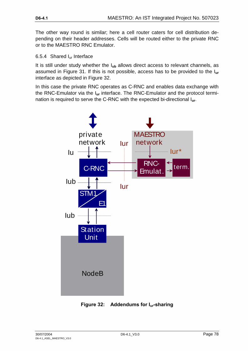
D6-4.1 MAESTRO: An IST Integrated Project No. 507023
30/07/2004 D6-4.1_V3.0 Page 78 D6-4.1_ASEL_MAESTRO_V3.0
The other way round is similar; here a cell router caters for cell distribution de-pending on their header addresses. Cells will be routed either to the private RNC or to the MAESTRO RNC Emulator.
6.5.4 Shared Iur Interface
It is still under study whether the Iub allows direct access to relevant channels, as assumed in Figure 31. If this is not possible, access has to be provided to the Iur interface as depicted in Figure 32.
In this case the private RNC operates as C-RNC and enables data exchange with the RNC-Emulator via the Iur interface. The RNC-Emulator and the protocol termi-nation is required to serve the C-RNC with the expected bi-directional Iur.
Stat ion Unit
E1STM1
NodeB
Iub
C-RNC
Iub
Iu
privatenetwork
RNC-Emulat .
IurIur*
MAESTRO network
term.
Iur
Figure 32: Addendums for Iur-sharing

D6-4.1 MAESTRO: An IST Integrated Project No. 507023
30/07/2004 D6-4.1_V3.0 Page 79 D6-4.1_ASEL_MAESTRO_V3.0
In principle both of the introduced sharing schemes are – roughly spoken – appli-cable. While Iub sharing requires the NodeB management (e.g., resource man-agement, node set-up, etc.) executed from outside via the OMC interface, the Iur sharing administration can be executed by the RNC module.
6.5.5 Conclusions

D6-4.1 MAESTRO: An IST Integrated Project No. 507023
30/07/2004 D6-4.1_V3.0 Page 80 D6-4.1_ASEL_MAESTRO_V3.0
7 ANNEX 2 - SPECIFICATION TABLES