imrt qa for measurement debate aapm 2014...
TRANSCRIPT

1
DEBATEIMRT Verification QA:
TO MEASURE
Moyed Miften, PhDUniversity of Colorado
Acknowledgments • Leah Schubert• Jenia Vinogradskiy• John Lucido• AAPM TG218

2
My Proposition is EASY to Argue for – 3 Words:
Measurement is the gold standard– No ifs, ands, or
buts…
If This Patient is one of Family Members
MRCT
NasopharynxPatinet
70 Gy to CTV 7 Field Setup

3
Patient-specific IMRT Verification QA Measurement• Designed to identify discrepancies between
planned and delivered doses• Detect gross errors in the radiation delivery • Minimizes reliance on the concept that all
potential sources of error in the IMRT process are known, characterized, and contained
• Ensuring the safety of patient, fidelity of treatment, and that the patient receives the desired treatment outcome
Q1. Which of the following regarding patient-specific IMRT QA verification measurement is true?
20%
20%
20%
20%
20%1. It is used to identify discrepancies between planned
and delivered doses2. It is used to detect gross errors in the IMRT process3. It is used to ensure the fidelity of the IMRT
treatment4. It minimizes the reliance on the concept that all
potential sources of error in the IMRT process are known and controlled
5. All the above
10
REF: 1. Kruse and Mayo, “Comment on “Catching errors with patient-specific pretreatment machine log file analysis,” PRO (2013). 2. Siochi and Molineu, "Patient-specific QA for IMRT should be performed using software rather than hardware methods," Med Phys (2013)

4
Review of Safety Fundamentals
SAFTEY: A Primer• Approximately 50% of cancer patients receive
radiation during the course of their treatment
• Majority of treatments are delivered safely
• Radiation error rate is ~ 0.2% per patient, or 1 in 500 (Ford, et. al IJROBP 2010)
• When errors occur, they can have serious consequences, not only resulting in direct harm to the patient, but an undermining of the public’s confidence in treatment

5
Recent Efforts to Improve Safety• Response to publicity instigated new
involvement in QA and safety issues within ASTRO and AAPM
• Safety symposia at recent ASTRO/AAPM meetings
• ASTRO’s Target Safely campaign• Safety white papers
– IMRT and SBRT: recently published in Med Phys and PRO
– HDR, IGRT, and Peer Review are in writing or editing stage
Recent Efforts to Improve Safety
“The 21st century is a new age of transparency and accountability. It’s a time of increasingly
complex treatments – propelled by ever-changing technology – that are creating new potential
hazards for working with radiation.”
- Anthony Zietman, MD, ASTRO Chair, 2011 ASTRO Annual Meeting

6
Complex Technologies in Radiotherapy• Rapid adoption of new technology using
sophisticated equipment
• Increase complexity of planning and delivery
Complex technology is sometimes indistinguishable from a black box: we don’t know what we don’t know

7
Errors in RadiotherapySuccess of radiotherapy
– Dependent on accuracy of delivered dose
Process of radiotherapy– Complex, multi-step process– Wide range of conditions treated, technologies used, technical
equipment, and professional expertise involved
Figure from Radiotherapy Risk Profile Technical Manual 2008 World Health Organization
When Do Events Occur?• Analysis of over 3000 incidents and near-misses
occurring between 1976-2007
• Significant harm– 55% planning stage– 45% during introduction of new systems/equipment
• Near-misses without known harm– 9% planning stage– 38% information transfer– 18% treatment delivery– 35% other
Shafiq et. al R&O 2009

8
Systems that are Hard-Wired for Success• Use of more than one single protective measure• Expects that mistakes will be made • Puts into place mechanisms for identifying mistakes
before they affect the patient’s treatment
Figure from Marks PRO 2011
High Potential for IMRT Errors• Treatment process is complex• Treatment relies on highly
technical systems• Technology can malfunction• Data transfer between systems
can malfunction• Miscommunication between
people can occur• Potential for human errors

9
Q2. The potential for IMRT errors are high because
20%
20%
20%
20%
20%1. Treatment is complex and relies on many complex
variables 2. Treatment clinical workflow is not well defined 3. planning systems use pencil-beam dose calculation
algorithms 4. Treatment are now more delivered with VMAT 5. Treatment data transfer systems are not used
appropriately
10
Hartford et al, “American Society for Therapeutic Radiology and Oncology (ASTRO) and American College of Radiology (ACR) Practice Guidelines for Intensity-Modulated Radiation Therapy (IMRT),” IJROBP (2009).
Patient-specific IMRT QA measurmenthas been hotly debated among physicists
• Smith & Dieterich, "It is STILL necessary to validate each individual IMRT treatment plan with dosimetric measurements before delivery," Med Phys (2011)
• Siochi and Molineu, "Patient-specific QA for IMRT should be performed using software rather than hardware methods," Med Phys (2013)
• Pawlicki et al, "Moving from IMRT QA measurements toward independent computer calculations using control charts," Radiother Oncol (2008)
• Ford et al, “Quality Control Quantification (QCQ): A Tool to Measure the Value of Quality Control Checks in Radiation Oncology,” IJROBP (2013)
• Kruse and Mayo, “Comment on “Catching errors with patient-specific pretreatment machine log file analysis,” PRO (2013)

10
Ford et al: data from 2 institutions
Ford et al IJROBP 2011
The need for or sensitivity of IMRT QA Measurement has been questioned

11
For verifying with measurements
For verifying with software & other tools
Jon Kruse Andrea Molina Chuck Mayo Charles Smith
Alf Soichi Sonja Dieterich Eric Ford Sasa Mutic
Jean Moran
Jean Moran
We ALL agree that we don’t want to have catastrophic errors or significant dosimetric inaccuracies

12
Arguments Made to Walk Away from IMRT QA Measurements
• Neither effective nor efficient• Labor intensive, time consuming, and less accurate• Relying on outdated QA procedures that focus on labor-
intensive measurement of precision• Measurement inaccuracies• Identifying the inaccuracy from a combined system
(delivery, TPS, measurement device...etc) is difficult• New paradigm for new technology is comprehensive
acceptance testing, comprehensive commissioning, and interconnectivity testing
• Beam-by-beam delivery provides no composite data• 3%/3mm/gamma does not identify clinically relevant
patient dose errors; what is the actual dose?• Create a false sense of safety with other, more sever
failure modes being overlooked• Software tools are better
– Machine log file analysis– MU programs
Arguments Made to Walk Away from IMRT QA Measurements

13
Steps Involved in IMRT Process
From ASTRO’s safety white paper on IMRT
Moran et. al PRO 2011
IMRT QA Checklist
ASTRO’s safety white paper on IMRT

14
Q3. The ASTRO white report, “Safety Considerations for IMRT,” by Moran et al stated that pre-treatment QA checks should include
20%
20%
20%
20%
20%1. Creation/calculation of the approved treatment
plan for the QA geometry using the dose per fraction specified for patient delivery
2. Verifying the integrity of the information transferred to the treatment management system
3. Verifying the correctness of MLC leaf positions, sequences, and fractional MUs
4. Verifying the accuracy of monitor units used for the patient dose calculation
5. All the above
10REF: Moran et al, “Safety Considerations for IMRT,” PRO (2011)
I AM ALSO UNAWARE
• Beside measurements, I am unaware of any methods that can verify the delivered IMRT fields have been modeled well enough to generate the desired dose.
• I am aware of no one who has successfully discovered or characterized them.
• Nor are there any TPS systems that can model all the parts of a linac and how their behavior changes with use.
From Charles Smith, Point counterpoint, Med Phys (2011):

15
My position is patient-specific IMRT QA measurement is necessary for the foreseeable future. HERE IS WHY
• We must AGREE that detecting errors which have significant dosimetric impact is essential
• Given the complexity and steps of the IMRT process, errors affecting dose can be made and have been made
• Planning systems, delivery technologies, R&V systems, system interconnectivity…etc can fail or problems can happen
• Quality measures using measurements are an indicator of problems and how big the error is
My Counter Arguments OR the TRUE PICTURE: TPS and Delivery Systems
• Unlike 3D systems, comprehensive commissioning of an IMRT planning system is an extremely difficult task to accomplish
• Unlike 3D dose, IMRT dose distributions are delivered via many micro MLC shapes and dynamic motion of many components (MLC , gantry motions, dose rate); very different from the TPS commissioning data.
• TPSs commissioning are based on measured data acquired from PDDs, profiles, and OFs of mainly large open fields
• Modeling dose delivery from finite MLC openings with measured data based from large open beams is extremely difficult
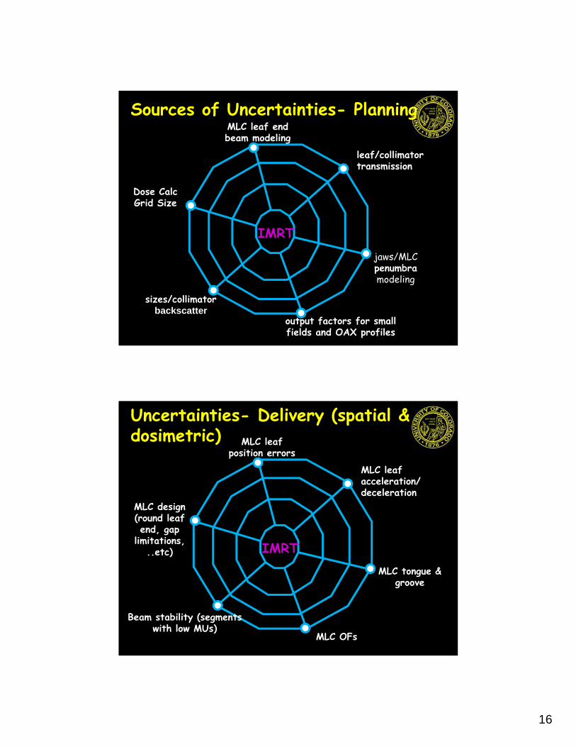
16
Sources of Uncertainties- Planning
IMRT
output factors for small fields and OAX profiles
jaws/MLC penumbramodeling
leaf/collimator transmission
MLC leaf end beam modeling
Dose CalcGrid Size
sizes/collimatorbackscatter
Uncertainties- Delivery (spatial & dosimetric)
IMRT
MLC OFs
MLC tongue & groove
MLC leaf acceleration/deceleration
MLC leaf position errors
MLC design (round leaf end, gap
limitations, ..etc)
Beam stability (segments with low MUs)
17
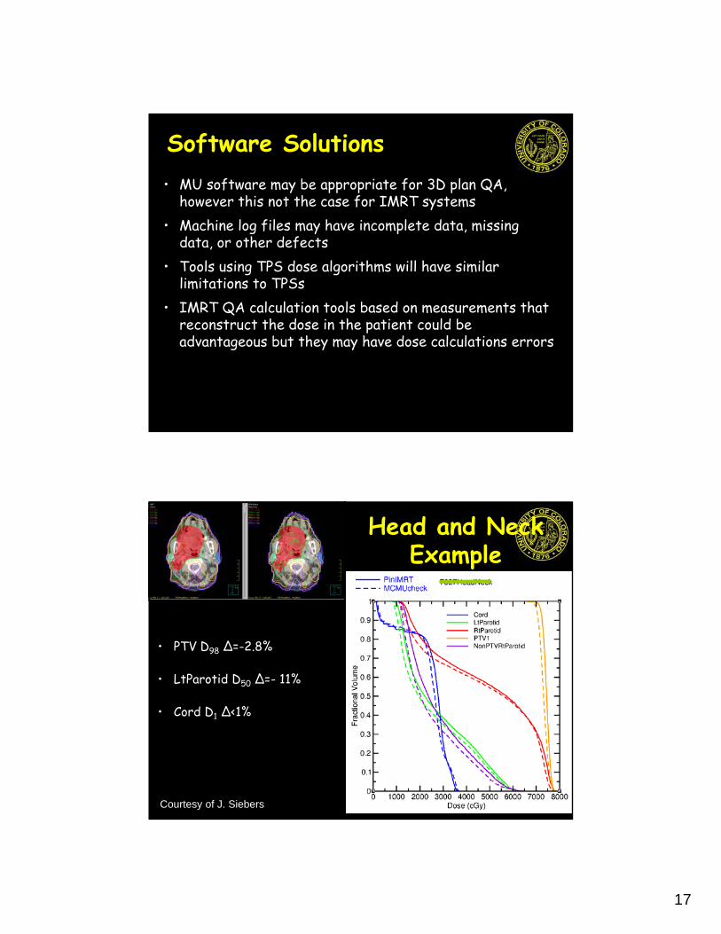
Software Solutions• MU software may be appropriate for 3D plan QA,
however this not the case for IMRT systems• Machine log files may have incomplete data, missing
data, or other defects• Tools using TPS dose algorithms will have similar
limitations to TPSs• IMRT QA calculation tools based on measurements that
reconstruct the dose in the patient could be advantageous but they may have dose calculations errors
• PTV D98 Δ=-2.8%
• LtParotid D50 Δ=- 11%
• Cord D1 Δ<1%
Head and Neck Example
Courtesy of J. Siebers

18
• PTV D98 Δ=- 2%
• LtParotid D50 Δ=- 3.5%
Head and Neck Calc using MC Fluence
Courtesy of J. Siebers
Dose Comparisons

19
Delivery Methods
True Composite(film & chamber)
True Composite(Device in coronal
direction)
True Composite(Device in sagittal
direction)
Field-by-FieldOR
Composite ALL Fields Summed (gantry @ 0o)
Composite ALL Fields Summed (device
perpendicular to gantry)
Methods to Compare Planned and Delivered Dose• Dose Difference (Ddiff)• Distance-to-Agreement (DTA)•

20
What is • γ is the rescaled Euclidean distance
between a calculated distribution & each point in a reference (measured) distribution
• Each spatial and dose axis is normalized by a criterion
• Renormalized “distance” defaults to DTA and Ddiff in shallow and steep dose gradient regions, respectively.
Courtesy of D. Low
Index
Courtesy of D. Low

21
Spatial Resolution Challenges
Courtesy of D. Low
Clinical Issues Using γ • Spatial resolution in evaluated distribution
is important unless some type of interpolation is used
• Dose difference criterion is intuitive• DTA criterion
– Spatial uncertainty (measurements)– How do we interpret γ failures?
Courtesy of D. Low

22
Failures• 100% passing would be nice!• Not practical• γ tool should be used as an indicator of
problems, not as a single indicator of plan quality
D-diff/DTA/ & passing rates don’t predict clinically relevant errors or appropriate evaluating for treatment plan acceptability• Point measurement and beam-by-beam evaluation may
obfuscate clinically relevant dose errors • While the published reports may cast doubt on the value
of measurements, it emphasizes that– Details of how the agreement between measured and
calculated results is determined are often poorly understood
– Passing rates have no spatial sensitivity, like DVHs, the location of the failed points is not provided with the failing rate.

23
Evaluation• statistics should be provided in a structure by
structure basis.• distribution should be reviewed rather than relying only
on distilled statistical evaluations such as g histograms • Clinical interpretation of failure results is a challenging
QA process. • Remember Quality measures are intended to set a
requirement for the performance of a system
Q4. Which of the following regarding the gamma metric is true?
20%
20%
20%
20%
20%1. It can be used as a single indicator of IMRT plan
quality specified for patient delivery2. It is a poor indicator of problems in the IMRT process3. It is independent of the dose distribution spatial
resolution 4. It could underestimate the clinical consequences of
certain dose delivery errors when the dose distribution is not evaluated on strcuture-by-srcturebasis
5. It is appropriate to ONLY check the gamma passing rate when evaluating the IMRT QA plan
10
REF: 1. Low et al, "A technique for the quantitative evaluation of dose distributions," Med Phys (1998)2. Low and Dempsey, "Evaluation of the gamma dose distribution comparison method," Med Phys (2003)

24
Let us look at the data carefully
Ford et al IJROBP 2011
Action Limits and Tolerance Levels

25
Action Limits (ALs) • Quality measures (QMs) set a requirement
for the performance of IMRT QA
• Action Limits degree to which the quality measures are
allowed to vary thresholds for when an action is required based on clinical judgment
• acceptability of a certain level of deviation from a QM
Tolerance Limits (TLs)• TLs boundary within which a process is
considered to be operating normally
• Measurements outside of a TL provide a warning that a system is deviating
– investigate to see if an issue can be identified and fixed
• Intent fix issues before they become a clinical problem (i.e. data outside of ALs)
26
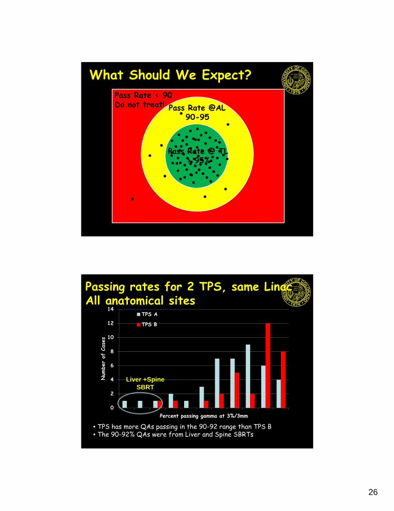
What Should We Expect?
Pass Rate @ TL > 95%
Pass Rate @AL90-95
Pass Rate < 90Do not treat!
Passing rates for 2 TPS, same LinacAll anatomical sites
• TPS has more QAs passing in the 90-92 range than TPS B• The 90-92% QAs were from Liver and Spine SBRTs
0
2
4
6
8
10
12
14
90 91 92 93 94 95 96 97 98 99 100
Num
ber
of C
ases
Percent passing gamma at 3%/3mm
TPS A
TPS B
Liver +Spine SBRT

27
Passing rates for 2 TPS, same LinacFractionated CNS cases
• TPS has more QAs passing in the 90-92 range than TPS B• The 90-92% QAs for TPS A were from Spine SBRTs
0
1
2
3
4
5
6
7
8
9
10
90 91 92 93 94 95 96 97 98 99 100
Num
ber
of C
ases
Percent passing gamma at 3%/3mm
TPS A
TPS B
Spine SBRT
Conclusions• The IMRT QA process should be designed to
detect significant errors within the limit of our quality measures
• We should always strive to improve our knowledge base but also recognize that there are things known and things unknown; measurement is the ultimate end test
• Relying on software or computer-based solutions may prevent us from detecting errors that are the outcome of software-bugs/poor software-design

28
Conclusions• Source of uncertainty among clinics using measurement-
based patient specific IMRT QA programs are the measurement and analysis tools used to interpret the QA results
• We should develop advanced software, improve measurement methods, and analysis tools for IMRT QA but this does not mean we should walk away form measurements
• Measurement should continue to be the centerpiece of IMRT QA programs
• I BELIEVE measurement is and will continue to be the best technique for IMRT QA
Future of IMRT QA • Guidelines to improve the understanding
and consistency of the IMRT QA process using measurements are needed
• Future approaches should involve using both measurement and software tools
• This may sound that we are doing more work but we can be efficient
• Sometime the right path is not always the easiest one

29
Thank You
CU Anschutz Medical Campus