imt installation and maintenance manual
TRANSCRIPT

INSTALLATIONAND
MAINTENANCEMANUAL
Self Steering Axle
Standard Trailer Axle
Drop Centre Axle
Visit us online at www.imtcorporation.com for the most recent version of this manual.

i
Table of Contents
Introduction .................................................................................................................................... 1Safety Warnings................................................................................................................. 1Part Number Description System....................................................................................... 2Parts List Assembly............................................................................................................ 3
General Information ...................................................................................................................... 4Welding Hardware to Axles (Methods) ............................................................................. 4Axle Preparation ................................................................................................................ 4Hardware Fit ...................................................................................................................... 5Welding Preparation .......................................................................................................... 5Location ............................................................................................................................. 6Welding Procedure............................................................................................................. 6Weld Bead Size.................................................................................................................. 7
Installation ...................................................................................................................................... 8Orientation ......................................................................................................................... 8Installing Axles And Associated Equipment ..................................................................... 8Allowable Axle Rotation.................................................................................................... 8Drilling into The Axle........................................................................................................ 9Axle Installation Procedure.............................................................................................. 10Slack Adjuster Installation ............................................................................................... 10
Manual Slack Adjusters: Installation ........................................................................ 10Manual Slack Adjusters: Brake Adjustment Procedure............................................ 11Roadside Adjustment ................................................................................................ 11Automatic Slack Adjusters: Installation.................................................................... 11Automatic Slack Adjusters: Brake Verification Procedure....................................... 12Automatic Slack Adjuster: Adjustment .................................................................... 12Roadside Adjustment ................................................................................................ 13
12 ¼” Brake Geometry .................................................................................................... 1416 ½” Brake Geometry .................................................................................................... 15
Maintenance ........................................................................................................................... 16Oil And Grease Suggested Intervals ................................................................................ 16Oil Properties ................................................................................................................... 16Axle Component Lubrication........................................................................................... 17
Lubrication Leakage ................................................................................................. 17Lubrication Preparation ............................................................................................ 17Grease Fitting Location............................................................................................. 17Lubrication Procedure............................................................................................... 17
Grease Packing Procedure ............................................................................................... 18Wheel Bearing Adjustment Procedure............................................................................. 19
Procedure IN018 Double Adjusting Nut System...................................................... 19Procedure IN019 Single Adjusting Nut System ....................................................... 19Procedure IN033 Conmet PreSet Hub - Double Nut System ................................... 20Procedure IN034 Conmet PreSet Hub - Single Nut System ..................................... 21
Procedure IN023 IMT Straight Axle Toe In, Toe out Verification ................................. 22Inspecting Axles And Associated Equipment.................................................................. 23
Proper Inspection Intervals ....................................................................................... 23Cracks ....................................................................................................................... 23Axle Straightness ...................................................................................................... 23Spindle Wear, Scratches, Rust And Pitting............................................................... 23

ii
Self Steer Assembly ...................................................................................................................... 24Procedure IN015 Caster Specifications For Axle At Ride Height................................... 25Procedure IN016 Self Steering Axle Alignment ***Field Check & Adjustment***...... 26Procedure IN016 Self Steering Axle Alignment ***New Installation*** ...................... 27Procedure IN017 Self Steer Axle Check List .................................................................. 28Procedure IN020 Self Steer Axle Toe In Adjustment...................................................... 29
When To Check Toe In............................................................................................. 29Procedure IN021 Removal / Installation Of Steering Link (pre 2003 SSA models) ....... 30Procedure IN043 Removal / Installation Of Steering Link (SSA models 2003 & later) . 31Procedure IN022 Installation - Ingersoll Self Steering Axles.......................................... 32Procedure IN024 Operation With Torpress and Locking Cylinder ................................. 33Air Circuit Diagram For SSA With Torpress And Locking Cylinder ............................. 34Electrical Circuit For Locking Cylinder And Auto Reverse Lift Command ................... 34SSA King Pin Bushing Wear Check................................................................................ 35Torque Specifications ...................................................................................................... 36

1
INTRODUCTION
The purpose of this manual is tofamiliarize yourself with an IMT axle.Topics included will cover:
• Installation• Adjustments• Maintenance• Inspections
This manual also contains information inchronological order to get your axleworking as soon as possible. Tables,diagrams, and charts for a common senseapproach are included to make this packageas complete as possible.
Your IMT nameplate on any axle is locatedon the center of the beam. It contains themodel and serial number. Your invoicenumber will also help to identify your axle.(Fig. 1)
Safety Warnings
This manual is intended to retain thesafety, dependability, and performanceengineered into IMT Axle Products. Studythis manual carefully before you performany installation or maintenance procedures. CAUTIONS and WARNINGS will beused to point out any circumstances that cancause personal injury or damagecomponents.
Before any repair or maintenance workthat requires raising a vehicle, secure it withlift stands that are properly rated. Alsomake sure wheel chocks are accuratelyinserted. Do not depend on wheel jacksalone for support of vehicle. Without proper training, safety equipment,and tools, serious if not fatal accidents canoccur. Read and understand procedures inthis manual before attempting any work. Do not sand, chisel, hammer, or alterlinings in any way. Do not blow brakeassemblies with high pressure air lines.Dust from linings should not be inhaled. Donot weld on wheel or heat wheel nuts withtire on. A potentially explosive tire failurecalled “Pyrolysis” can occur. Do not use a chisel to remove/installspindle nuts. Always use the right socketsize and torque wrench, following torqueprocedures.
If you have any further questions, please contact:IMT
347 King Street WestBox 250
Ingersoll, OntarioPhone: 1-800-663-AXLE
519-485-2210Fax: 519-485-2163
!
IMT
Fig. 1

Fig. 2
PA
RT N
UM
BE
R D
ES
CR
IPTIO
N S
YS
TEM
2
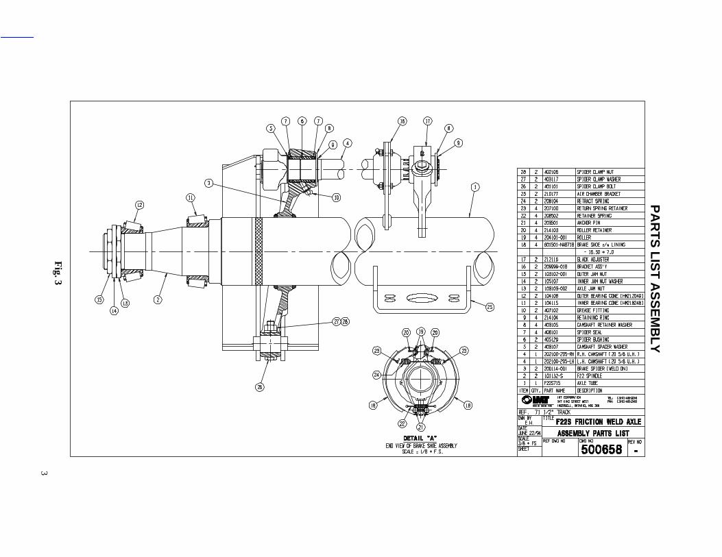
3F
ig. 3
PA
RT
S L
IST
AS
SE
MB
LY

4
GENERAL INFORMATION
Before installation can begin, now is the time to inspect your IMT axle for any flaws or damagethat has occurred at the factory or during shipping.
WELDING HARDWARE TO AXLES
MethodsFour methods may be used to weld hardware to trailer axles:• Shielded metal arc (stick electrodes)• Gas metal arc (MIG, solid wire)• Gas tungsten arc (TIG)• Flux cored arc (tubular wire)
American Welding Society (AWS) classifications and specifications for these four methods areshown in Table 1.
Method for WeldingCarbon & Low Alloy Steels
AWSElectrode
Classification AWS SpecificationsShielded Metal Arc E70XX A5.1 / A5.5
Gas Metal Arc ER70S-X A5.18Gas Tungsten Arc ER70S-X A5.18
Flux Cored Arc E70T-X A5.20Table 1.
AWS WELDING SPECIFICATIONS
The weld tensile strength must be 70,000 psi as per AWS specifications. Weld tensile strengthswhich are either higher or lower than this rating are not acceptable. The best fusion and strength will be obtained using the voltage, current and shielding mediumrecommended by the electrode manufacturer. If the shielded metal arc method is used, electrodesmust be clean, dry and have been stored per AWS specifications (AWS Section 4.5.2).
AXLE PREPARATION
The area to be welded must be free of grease, dirt, paint, slag and other contaminants. Thesecontaminants may affect weld quality. Never weld when the axle is cold. The axle and brackets to be welded should be storedovernight in a heated room and be at a temperature of at least 60ºF prior to welding. This willreduce the chance of forming an area of brittle material adjacent to the weld. If temperature requirements are not met, moderately pre-heat the weld area to a maximumtemperature of 200ºF using a “Rosebud”. Do not concentrate heat in one area. Rather, slowlyheat a wide area around the joint to be welded. Verify axle temperature using a temperaturesensitive crayon or other appropriate means.
5
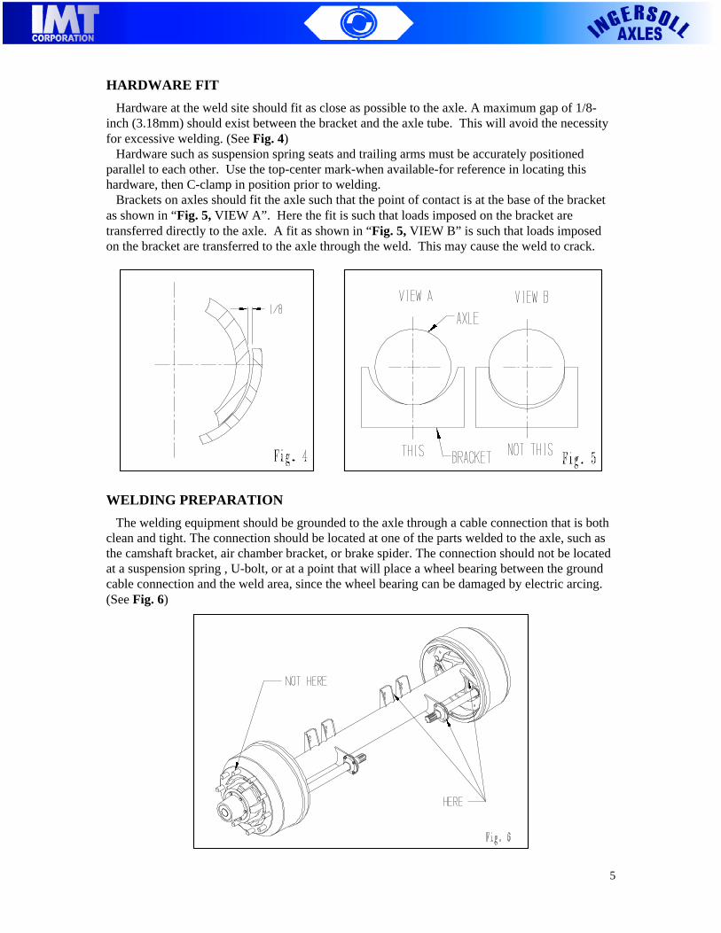
HARDWARE FIT
Hardware at the weld site should fit as close as possible to the axle. A maximum gap of 1/8-inch (3.18mm) should exist between the bracket and the axle tube. This will avoid the necessityfor excessive welding. (See Fig. 4) Hardware such as suspension spring seats and trailing arms must be accurately positionedparallel to each other. Use the top-center mark-when available-for reference in locating thishardware, then C-clamp in position prior to welding. Brackets on axles should fit the axle such that the point of contact is at the base of the bracketas shown in “Fig. 5, VIEW A”. Here the fit is such that loads imposed on the bracket aretransferred directly to the axle. A fit as shown in “Fig. 5, VIEW B” is such that loads imposedon the bracket are transferred to the axle through the weld. This may cause the weld to crack.
WELDING PREPARATION
The welding equipment should be grounded to the axle through a cable connection that is bothclean and tight. The connection should be located at one of the parts welded to the axle, such asthe camshaft bracket, air chamber bracket, or brake spider. The connection should not be locatedat a suspension spring , U-bolt, or at a point that will place a wheel bearing between the groundcable connection and the weld area, since the wheel bearing can be damaged by electric arcing.(See Fig. 6)
6
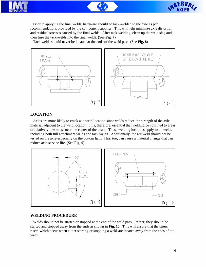
Prior to applying the final welds, hardware should be tack-welded to the axle as perrecommendations provided by the component supplier. This will help minimize axle distortionand residual stresses caused by the final welds. After tack-welding, clean up the weld slag andthen fuse the tack-welds into the final welds. (See Fig. 7) Tack welds should never be located at the ends of the weld pass. (See Fig. 8)
LOCATION
Axles are more likely to crack at a weld location since welds reduce the strength of the axlematerial adjacent to the weld location. It is, therefore, essential that welding be confined to areasof relatively low stress near the center of the beam. These welding locations apply to all weldsincluding both full attachment welds and tack welds. Additionally, the arc weld should not betested on the axle-especially on the bottom half. This, too, can cause a material change that canreduce axle service life. (See Fig. 9)
WELDING PROCEDURE
Welds should not be started or stopped at the end of the weld pass. Rather, they should bestarted and stopped away from the ends as shown in Fig. 10. This will ensure that the stressrisers-which occur when either starting or stopping a weld-are located away from the ends of theweld.

7
All welds should be made in one continuous pass rather than stopping and starting the weldpasses as shown in Fig. 11. When attaching a bracket using multiple welds, axle distortion can be minimized bysequencing the welds. This involves alternating weld passes between the front and rear of anindividual bracket and between the brackets located on the axle roadside and curbside. (See Fig.12). This is in contrast to applying all the welds at one bracket location. Note further that the first weld pass should be made on the front side of the bracket. This willhelp ensure that any warping will result in the more desirable “toe-in” condition, rather than theless desirable “toe-out” condition.
WELD BEAD SIZE
The maximum weld bead size allowed-regardless of whether the weld is achieved with a singleor multiple pass-is 1/2 inch (12.7mm) on round axles.

8
INSTALLATION
ORIENTATION
Because of the many variations of IMT axles, orientation is important. A good rule of thumb isto align cam rotation with wheel rotation in the forward direction. (See Fig. 13). If cam/wheelrotation is opposite, natural frequencies can cause brake squealing and vibrations.
Consult IMT for further information.
INSTALLING AXLES AND ASSOCIATED EQUIPMENT
Axle Top-Center Location Some trailer axle models are built with some type of mark, such as a drilled hole or a punchmark, which locates the top center of the beam. These markers can be used to orient the axleassembly on the suspension and identify the center of the beam so the suspension brackets can belocated from a central reference point. (See Fig. 14)
ALLOWABLE AXLE ROTATION
WARNING: This section providesinformation on the allowable rotation of traileraxles. It does not, however, attempt to evaluateany possible interference between the axleassembly and other trailer componentsresulting from this rotation. Responsibilityfor maintaining adequate clearance betweenvarious components lies with the vehiclemanufacturer.
WARNING: Installation of axles with thetop-center other than as specified will void thewarranty and could result in premature fatiguedamage to the axle.
!

9
Cambered trailer axles must be installed so that the top-center mark is located at the exact top ofthe axle. Non-cambered trailer axles can be installed so that the top-center mark is not located at theexact top of the axle. If rotation of the axle is allowed, the top-center mark can be rotated 22 1/2degrees away from the exact top position. (See Fig. 15)
NOTE: If top-center rotation is allowed, the hardware for the specific brake model must remain withinthe rotational limitation shown in Fig. 16.
DRILLING INTO THE AXLE
NOTE: This document makes recommendations as to the most logical location in which todrill a hole into an axle tube. Any components altered on an axle are the responsibility of themanufacturers who modify them. Auxiliary trailer equipment such as central tire inflation systems may require drilling of a holeinto the axle tube. In order to minimize the effect of hole drilling on axle strength, the hole shouldbe located in an area of the tube that experiences the least stress. Therefore, good design practicedictates that the hole be located as close to the neutral axis of the axle tube as possible. (See Fig.17)

10
AXLE INSTALLATION PROCEDURE
NOTE: Due to the many variations in suspension design, proper suspension installation is theresponsibility of the trailer or suspension manufacturer.
1. Position the suspension components on the axle. Check to ensure that they fit the axleproperly. Refer to the guidelines on welding contained within this Recommended Practice. 2. Locate the axle top-center and follow guidelines regarding allowable axle rotation aspreviously stated in this Recommended Practice. 3. Weld the suspension components to the axle according to suspension manufacturer’sguidelines and this Recommended Practice. 4. Position the axle in place under the suspension while ensuring that the proper spacing andalignment requirements are met. 5. Snug the U-bolts with an impact tool. Torque the U-bolts to manufacturer’s publishedrequirements using a calibrated torque wrench. Tighten the U-bolts in a crisscross pattern. Becareful not to overtighten the U-bolts since this may damage the axle at the point which theU-bolts contact the axle. 6. Following axle installation and alignment, inspect the assembly to ensure the following:
• All suspension springs are properly located on the wear pad.• Adequate clearance exists between the axle and the trailer frame and suspension
components, both when the axle is loaded and unloaded.• All bolts have been tightened to proper torque values.
SLACK ADJUSTER INSTALLATION
There are two types of slack adjusters: the manual type and the automatic type. First, we willlook at manual slack adjusters.
Manual Slack Adjusters: Installation
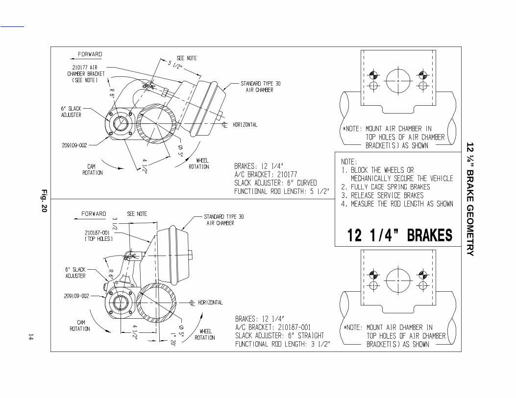
1. With the proper spider/cam hardware installed, completely push the cam against the spiderface. 2. Install the slack on the cam spline so that the adjusting hex is accessible for servicing. 3. Adjust the clevis pin on the air chamber rod to the required length (ref. 12 ¼” and 16 ½”brake geometry Fig. 20 - 21). 4. Align the slack adjuster arm to the clevis and insert the provided pin through the alignedholes. Secure the clevis pin with a cotter pin. 5. Check that the angle between the air chamber rod and the slack adjuster center lines are105° +0°/-2° when the brakes are in their released position. 6. Install the camshaft retaining washer and retaining ring on the end of the cam shaft. Be sureto shim clearance to slack adjuster manufacturer’s specified tolerance. 7. Tighten the jam nut on the air chamber rod to lock the clevis into position (1/2-20 300-400in.lbs. 5/8-18 400 in.lbs.). 8. After installation, make sure there is enough clearance for both applied and released brakepositions. Also check that the slack adjuster rotates freely without binding.

11
Manual Slack Adjusters: Brake Adjustment Procedure
Safely raise the vehicle so that the tires spin freely. Clean the locking sleeve area so that thesleeve can return to its locked position without any obstructions. Place a socket or wrench on theadjusting hex and sink the locking sleeve to disengage it. While rotating the tires, adjust the setscrew until the shoes contact the drum. Then, back off the adjusting hex until the tires rotatefreely. Make sure the locking sleeve raises to its locked position. Note that the actuator strokeshould be as short as possible without the brakes dragging.
Roadside Adjustment
If the vehicle cannot be raised up, again clean the locking sleeve area thoroughly. Place asocket or wrench on the adjusting hex sinking the locking sleeve. Turn the adjusting hex until itstops, indicating that the shoes have made contact with the drum. Pull on the slack adjuster to seeif there is any movement. If it will not move, the adjusting hex was turned in the properdirection. If there is movement, then the adjusting hex was turned in the wrong direction and willhave to be turned in the opposite direction until it stops, locking the shoes against the drums.After determining solid shoe contact, back off the adjusting hex 1/2 turn for new linings, or 1/4turn for worn linings. The actuator stroke should be as short as possible without the brakesengaging. Make sure the locking sleeve moves up to its locked position. If it does not, the slackadjuster can back itself off.
Automatic Slack Adjusters: Installation (A-arm link type, B-anchor bracket type)
1. With the proper spider/cam hardware installed, completely push the cam against the spiderface. 2A. Adjust the clevis on the air chamber rod to the required length and install air chamber (ref.12 ¼” and 16 ½” brake geometry - see Fig. 20 - 21). 2B. Place clevis pin on air chamber rod. Repeat (2A). 3A. Place swing tool or template onto the cam spline and rest against clevis. 3B. Rotate the control arm away from the adjusting hex until it comes to a complete stop. Notethe indicator between the slots. 4A. Reposition clevis until 1/4” link pin holes are aligned. This will ensure a proper slackadjuster angle and fit. 4B. Tighten all anchor bracket fasteners while ensuring that the control arm does not move. 5A. Install slack adjuster on the camshaft so that the adjusting hex is accessible for servicing.Be sure to shim the slack adjuster to the manufacturer’s specifications. 5B. Install auto slack adjuster onto camshaft with adjusting hex away from the air chamber. Besure to shim the slack adjuster to the manufacturer’s specifications. 6A. Rotate the adjusting mechanism if needed to insert the clevis and link pins. Install cotterpins. 6B. Rotate the adjusting hex to align the clevis hole with the slack adjuster hole and insertclevis pin. Note: Do not install cotter pin, see adjustment procedure to check for properinstallation.Then install cotter pin. 7A. Tighten jam nut on the air chamber rod.
Note: See Automatic Slack Adjuster Manufacturer’s instructions for detailedillustrations and procedures.

12
Automatic Slack Adjusters: Brake Verification Procedure
Air Chamber Power Stroke: Apower stroke at 80-90 psi brakeapplication pressure will check boththe adjustment and foundation brakecondition. Apply the followingprocedure.
1. Measure the distance from thebottom of the air chamber to thecenter of the clevis pin on allwheels. See Fig. 18.
2. Apply brakes repetitively untilthe air reservoir indicator reads 90 -100 psi. Then have someone applyfull brakes and hold.
3. Again, measure the distancefrom the bottom of the air chamberto the center of the clevis on allwheels. See Fig. 19.
4. The difference betweenapplied and released brakes is calledthe power stroke. If the measureddistance is no more than the legalmaximum stroke shown in Table 2,the procedure is complete.
Automatic Slack Adjusters:Adjustment
Place a socket or wrench over theadjusting mechanism. Turn it so theshoes contact the drum. Pull theslack adjuster by hand to make sureit does not move. If it does move,adjustment was made in the wrongdirection. Turn the adjustingmechanism in the opposite directionuntil the shoes are contacting thedrum and the adjusting mechanismstops.
Air ChamberType
Maximum Legal Stroke
12 1 3/8”16 1 3/4”20 1 3/4”24 1 3/4”
24 Long Stroke 2”30 Long Stroke 2 1/2”
30 2”36 2 1/4”
Table 2

13
Reverse the rotation 1/2 turn backing off the slack adjuster. Measure the air chamber powerstroke at 80-90 psi as mentioned in the Brake Verification Procedure. Make a free strokemeasurement (distance from rest to drum contact using a pry bar). You should be measuring adistance between 3/8” - 5/8”. If you cannot maintain the maximum legal stroke and the free stroke is less than 3/8”, contactthe brake manufacturer for foundation or brake geometry problems.
Roadside Adjustment
If the vehicle cannot be raised, use a pry bar to pull back on the slack adjuster. If there is morethan 5/8” movement, an adjustment is required. Block the wheels or secure the vehicle. On thebrakes to be adjusted, the spring brakes have to be caged or released with air. Rotate the adjusting mechanism on the slack adjuster until the shoes contact the drum. Use apry bar to see if there is any movement. If there is any, the adjustment was made in the wrongdirection. Adjust in the opposite direction until the shoes contact the drum. Note: You shouldhere a muffled knock when hitting the locked drum with a wrench. Back off the slack adjusterby small increments tapping the drum until an unobstructed chime is heard. Using a pry bar, recheck the slack adjuster by pulling it back, measuring no more than 5/8”of movement. If it is more, than the adjustment was done improperly or there is a problem withthe brake foundation.
12 ¼” B
RA
KE
GE
OM
ET
RY
14
Fig
. 20

15
16 ½” B
RA
KE
GE
OM
ET
RY
Fig
. 21

16
MAINTENANCE
Oil and Grease Change Suggested Intervals:
Due to varying load and driving conditions, service intervals will vary. Below is a generallyaccepted guideline on which maintenance scheduling can be observed. Always clean partsthoroughly with proper solvents and equipment. Do not use gasoline or steel brushes. Neverrefill the hub with old oil. Extra attention should be given to seals. Contaminated lubricants can quickly destroy theentire wheel assembly.
DISTANCEOR TIME
OIL GREASE BRAKECOMPONENTS
1000mi1600km
Inspect oil level in hub replace ifcontaminated. Check for leaks.Replace if hub removed forservicing. See indicated “ADDand FULL rings on the hub cap.
------------------------------------------------------------------
----------------------------------------------
12,000mi19,200km
----------------------------------------------------------------------------------
--------------------------------------------------------------------
Check brakes foradjustment.
30,000mi48,000km
or6 monthinterval
Heavy-Duty (On/Off road)Change oil lubricant
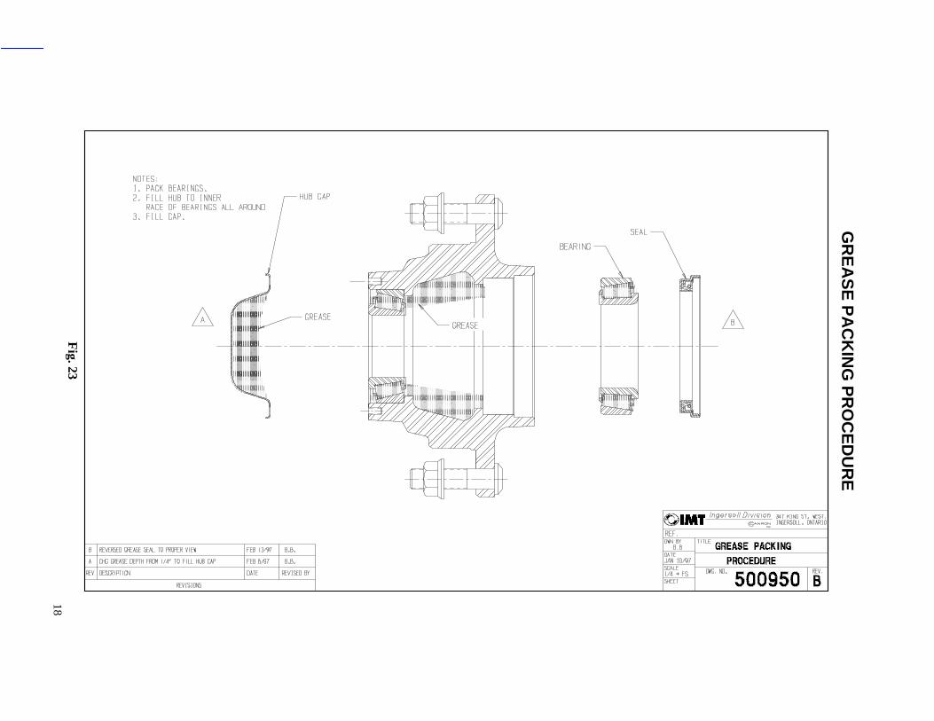
Heavy Duty (On/Off Road)Regrease bearings. SeeDWG 500950
Check lining wear.Check cam andspider bushings forwear. Grease brakeactuating parts.
100,000mi160,000km
or1 yr interval
Standard-Duty Change oillubricant
Standard Duty Regreasebearings. See DWG 500950 -----------------------
750,000mi1,200,000km
Replace synthetic “Semi-Fluid” Long Life Greases: Also replace if hub is removed forservicing.
Table 3
Lubricant Properties:
IMT suggests the following grease properties: DO NOT MIX LUBRICANTSSoap Type - Lithium Complex or EquivalentDropping Point - 446°F (230°C) MinimumConsistency - NLGI No. 2 or No.1Additives - Corrosion & Oxidation Inhibitors, EP OptionalBase Oil - Solvent Refined Petroleum Oil
Oils generally recommended are:Gear Oil API GL-5 Performance Level
SAE 90 Normally PreferredSAE 75W, SAE 80W Extreme Cold EnvironmentSAE 140 Extreme Hot Environment
!
17
AXLE COMPONENT LUBRICATION
This section offers recommendations for periodic lubrication of trailer brake componentsinstalled on trailer axles. Many fleets use their trailer inspection interval as their trailer lubricantinterval. For information on brake lubrication intervals, refer to TMC RP 607 and 609.
Refer to TMC RP 624, Lubricant Fundamentals for more information.
Lubricant Leakage
Inspect the axle for lubricant leakage. Wear or damage to seals can result in either leaks orcomponent contamination and could ultimately lead to wheel-end loss. Any signs of lubricantleakage should be investigated, and the seals or rings replaced if any damage or improperlyinstalled components are found. Seal leakage can lead to loss of wheel-end lubricant andultimately cause the wheel end to overheat.
Lubrication Preparation
If possible, clean the trailer prior to lubrication. This will help the mechanic locate the greasefittings and spot any problems with the trailer. Park the trailer on level ground and set the parking brakes. Be sure the landing gear is in placeand free of defects. Chock the wheels to prevent the trailer from rolling, and block accessibilityto the trailer so that no one attempts to hook it up and drive it off. Locate all fittings to be lubricated and wipe off any excess grease or road film with a clean ragor paper towel.
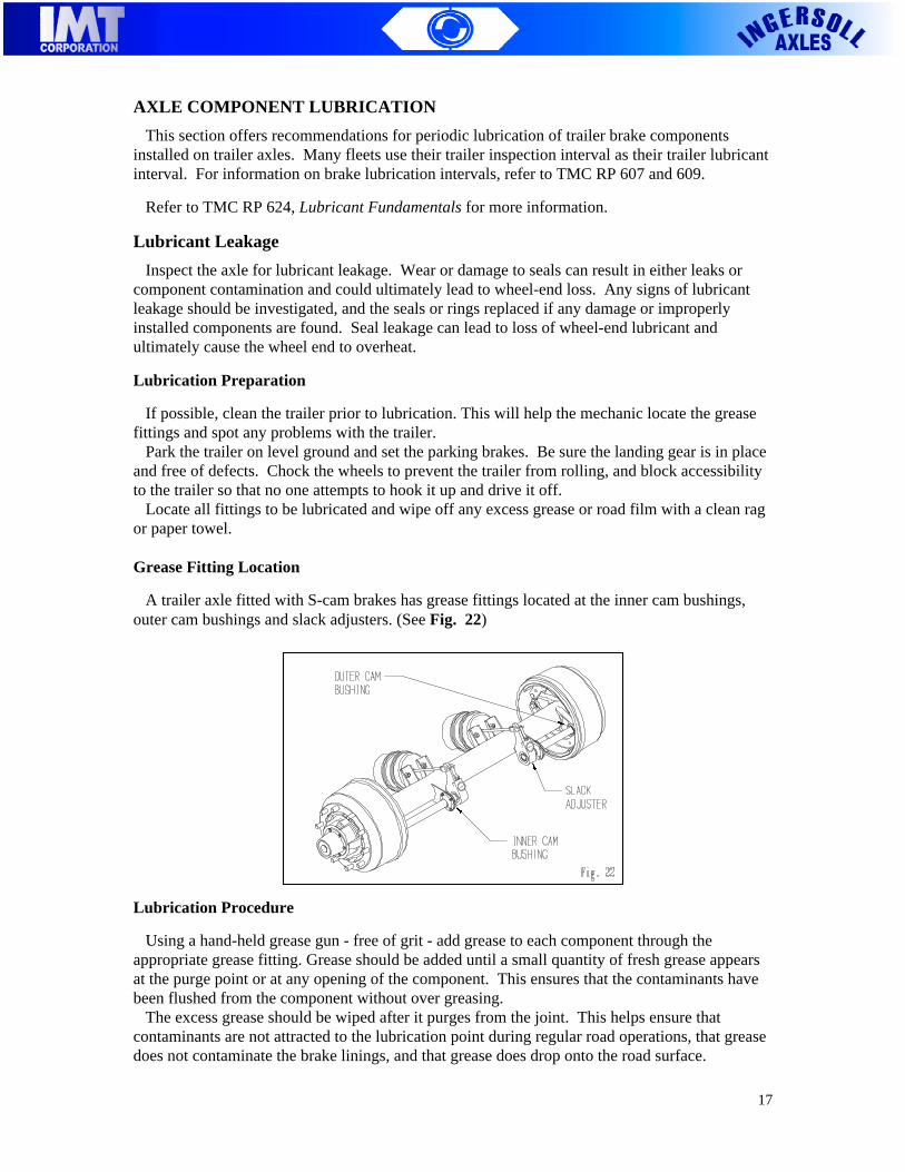
Grease Fitting Location
A trailer axle fitted with S-cam brakes has grease fittings located at the inner cam bushings,outer cam bushings and slack adjusters. (See Fig. 22)
Lubrication Procedure
Using a hand-held grease gun - free of grit - add grease to each component through theappropriate grease fitting. Grease should be added until a small quantity of fresh grease appearsat the purge point or at any opening of the component. This ensures that the contaminants havebeen flushed from the component without over greasing. The excess grease should be wiped after it purges from the joint. This helps ensure thatcontaminants are not attracted to the lubrication point during regular road operations, that greasedoes not contaminate the brake linings, and that grease does drop onto the road surface.
18
GR
EA
SE
PA
CK
ING
PR
OC
ED
UR
E
Fig. 23

19
WHEEL BEARING ADJUSTMENT PROCEDURE
IMT endorses TMC’s Recommended Wheel Bearing Adjustment Procedure RP 618.The objective of these procedures is to obtain 0.001” to 0.005” end play.
PROCEDURE IN018 (See Fig. 24)
Double Adjusting Nut System: F19, A21, F22, F23, A26
1. Tighten the adjusting nut (A) to a torque of 200 ft-lbs. (271 N�m) while rotating the wheel.2. Back off the adjusting nut (A) one full turn.3. Tighten the adjusting nut (A) to a final torque of 50 ft-lbs. (68 N�m) while rotating the wheel.4. Back off adjusting nut (A) 1/4 to 1/3 turn and install lock washer (B) to nearest hole.5. Install outer jam nut (C) and torque to 300-400 ft-lbs. (407-542 N�m).6. Acceptable end play is 0.001” (.025mm) to 0.005” (.013mm) measured with a dial indicator.7. Verify that the wheel rotates freely when adjustment is complete.
PROCEDURE IN019 (See Fig. 25)
Single Adjusting Nut System: F23, A24, F24
1. Install lock washer (B).2. Tighten adjusting nut (A) to a torque of 200 ft-lbs. (271 N�m) while rotating wheel.3. Back off adjusting nut (A) 1 full turn.4. Tighten the adjusting nut to a final torque of 50 ft-lbs. (68 N�m) while rotating the wheel.5. Back off adjusting nut (A) 1/6 to 1/4 turn to the nearest locking hole.6. Install cotter pin.7. Acceptable end play is 0.001” (.025mm) to 0.005” (.013mm) measured with a dial indicator.8. Verify that the wheel rotates freely when adjustment is complete.
20
REVISED JUNE 20, 2000
IMT PROCEDURE IN033
WHEEL BEARING ADJUSTMENT PROCEDURE
CONMET PreSet HUB
THIS TYPE OF HUB IS PRE-ASSEMBLED WITH A SEAL AND A SPACERBETWEEN THE BEARING CONES
For Double Nut System: F22, F23
THE OBJECTIVE OF THIS PROCEDURE IS TO OBTAIN A PRELOAD ONTHE CONES AND SPACER.
1. FOR OPERATION WITH SYNTHETIC GREASE: Completely coat the spindle with afilm of grease, including the seal journal. Always use the same grease that will beused in the hub.
2. Lubricate the inside diameter of the seal.
3. Install the hub onto the spindle.
4. Remove the plastic bearing retainer and install the inner nut.
5. Torque the inner nut to 300 ft-lbs: no back off.
6. Install the locking washer and torque the outer nut to 200 ft-lbs.
7. Apply a ring of grease around the nuts.
8. Install the hub cap. Use Conmet, Stemco Sentinel, or equivalent “filtered vent” hubcap.
9. Fill the hub with 1.0 lbs. to 1.25 lbs. of grease through the fill hole in the hub.
10. FOR OPERATION WITH OIL: Pre-lubricate inside of seal only. Use “oil” hub capand fill to level on sight glass.
11. There should be 0.000” to 0.004” end play.
12. Verify that the wheel turns freely when adjustment and locking procedures arecomplete.
REVISED JUNE 20, 2000

21
IMT PROCEDURE IN034
WHEEL BEARING ADJUSTMENT PROCEDURE
CONMET PreSet HUB
THIS TYPE OF HUB IS PRE-ASSEMBLED WITH A SEAL AND A SPACERBETWEEN THE BEARING CONES
For Single Nut System: F23, F24
THE OBJECTIVE OF THIS PROCEDURE IS TO OBTAIN A PRELOAD ONTHE CONES AND SPACER.
1. FOR OPERATION WITH SYNTHETIC GREASE: Completely coat the spindle with afilm of grease, including the seal journal. Always use the same grease that will beused in the hub.
2. Lubricate the inside diameter of the seal.
3. Install the hub onto the spindle.
4. Remove the plastic bearing retainer and install the locking washer and the spindlenut.
5. Torque the spindle nut to 300 ft-lbs.: no back off. Lock the spindle nut. If required,advance the nut to the next locking position.
6. Apply a ring of grease around the nut.
7. Install the hub cap. Use Conmet, Stemco Sentinel, or equivalent “filtered vent” hubcap.
8. Fill the hub with 2.2 lbs. to 2.5 lbs. of grease through the fill hole in the hub.
9. FOR OPERATION WITH OIL: Pre-lubricate inside of seal only. Use “oil” hub capand fill to level on sight glass.
10. There should be 0.000” to 0.004” end play.
11. Verify that the wheel turns freely when adjustment and locking procedures arecomplete.

22
PROCEDURE IN023 SEPT 20,2001
IMT STRAIGHT AXLE TOE-IN, TOE-OUT VERIFICATION
Figure AWHEEL TOE-IN
(TOP VIEW OF AXLE WITH DUALS)
Note: With wheels off the ground, scribe a fine line on the tire tread all around the tireto aid in the measurement of "A" and "B".
Toe-in: “A” is smaller than “B”.Toe-out: “A” is larger than “B”.(See Figure A)
To be correctly aligned, wheel toe-in or toe-out must be within the limits of .25",6.35 mm, 0.358 degree, or 21 minutes toe-in, and .063", 1.59 mm, 0.09 degree, or 5minutes toe-out. Toe-in or toe-out which exceeds these limits will cause increased tirewear.

23
INSPECTING AXLES AND ASSOCIATED EQUIPMENT
Proper Inspection Intervals
Trailer axles should be inspected for cracks, wear and leaks every six months or 50,000 miles.
Cracks
The entire axle tube should be visually inspected for cracks. Any cracks found in the tubingindicate immediate axle replacement is necessary. Repair welding of the axle tube is prohibited. Welds attaching brake spiders, camshaft brackets, air-chamber brackets and suspensioncomponents should be inspected for cracks. If a crack is detected, determine if it penetrates intothe tubing. If a crack penetrates into the axle tubing, repair welding is not permitted and the axlemust be replaced.
Axle Straightness
The axle should meet the trailer manufacturer’s specifications for straightness. Refer to RP 708regarding this inspection. Obvious signs of improper axle straightness include premature andexcessive tire wear. Trailer axle manufacturers do not approve of straightening axles in the shop.Overloaded or bent axles should be replaced.
Spindle Wear, Scratches, Rust and Pitting
Any cracks found in the spindle require immediate axle replacement. Repair is not allowed. Surface rust, scratches, or slight pitting on the wheel spindle bearing or seal journals may bepolished or sanded out with emery or crocus cloth. Do not reduce the diameters of the journalsbeyond the axle manufacturer’s specifications. Excessive pitting, scratches or fretting on thespindle bearing or seal journals-covering more than 50 percent of the surface-require immediateaxle replacement. Spindle threads may be cleaned with a wire brush or chased with a die. Repair welding of spindle threads are not permitted. Consult IMT if any wear is questionable.
!

24
SE
LF
ST
EE
R A
SS
EM
BL
Y
Fig. 27

25
PROCEDURE IN015 March 02, 2005
IMT Self Steer Axle (700000 SERIES)CASTER SPECIFICATIONS FOR AXLE AT RIDE HEIGHT - LOADED
CAUTION1. Changing tire diameters on the SSA or the primary suspensions willaffect the SSA caster position.
• Increasing the SSA tire diameter will cause the SSA caster to gonegative which is undesirable.
• Decreasing the primary suspensions’ tire diameter will cause theSSA caster to go negative which is undesirable.
2. Changing the tractor fifth wheel height will affect the SSA casterposition.
• Decreasing the tractor fifth wheel height (new tractor) below thedesign height for the trailer, will cause the caster to go negativewhich is undesirable.
3. If the SSA caster measures more than 2 degrees negative, when tractorand trailer are properly coupled on level ground, consult IMT to develop acorrective action.

26
PROCEDURE IN016***FIELD CHECK AND ADJUSTMENT***
SELF-STEERING AXLE ALIGNMENT
NOTE: VERIFY AND ADJUST TOE-IN PER IMT PROCEDURE IN020 BEFORESTARTING THIS ADJUSTMENT.
1. Inspect suspension and axle for mechanical wear, damage, or missing parts.Repair or replace parts as required before starting toe-in and alignment.
2. Verify and adjust SSA king pin positions relative to trailer king pin, per Fig. 29:Y1=Y2. Use suspension adjustment mechanism to set this position.
3. Fixed Axle must be aligned first. Verify the SSA axle end alignment with the trailerking pin, and adjust with the centralizer air bag position bolts per Dwg. 700196.Centralizer bag must be at normal working pressure. Set Z1=Z2 per Fig. 29.
4. Lift SSA to release any adjustment tension still in the steering mechanism. Lowerand apply normal equalized load on the axle, and verify toe-in and alignmentagain. Adjust as required. Repeat until the axle measures correct toe-in andalignment.
27
PROCEDURE IN016***NEW INSTALLATION***
SELF-STEERING AXLE ALIGNMENT
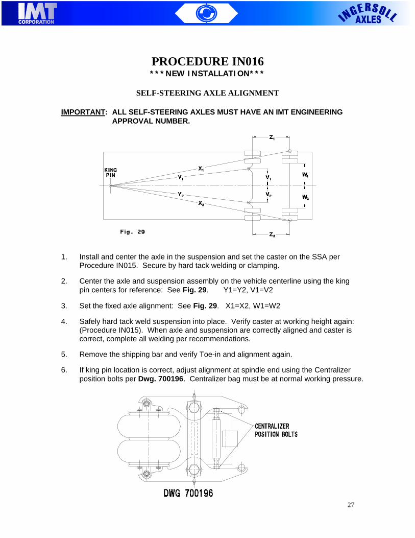
IMPORTANT: ALL SELF-STEERING AXLES MUST HAVE AN IMT ENGINEERING APPROVAL NUMBER.
1. Install and center the axle in the suspension and set the caster on the SSA perProcedure IN015. Secure by hard tack welding or clamping.
2. Center the axle and suspension assembly on the vehicle centerline using the kingpin centers for reference: See Fig. 29. Y1=Y2, V1=V2
3. Set the fixed axle alignment: See Fig. 29. X1=X2, W1=W2
4. Safely hard tack weld suspension into place. Verify caster at working height again:(Procedure IN015). When axle and suspension are correctly aligned and caster iscorrect, complete all welding per recommendations.
5. Remove the shipping bar and verify Toe-in and alignment again.
6. If king pin location is correct, adjust alignment at spindle end using the Centralizerposition bolts per Dwg. 700196. Centralizer bag must be at normal working pressure.

28
PROCEDURE IN017
SELF STEERING AXLE CHECK LIST
1. Suspension should be the right model and capacity. Install suspension shock kit if unusualaxle hop or bounce is experienced. Compare the SSA to the tandem for reference.
2. Check for mechanical looseness/wear/damage on the suspension/axle/frame and all othercomponents.
3. Verify toe-in: Procedure IN020.
4. Verify alignment: Procedure IN016.
5. Verify caster: Procedure IN015.
6. Tires (both sides) must be:(a) Same size designation and tread.(b) Same type: all radial -or- all bias ply.(c) Balanced.(d) Inflated to recommended pressure for actual load.
7. Rims (both sides) must be same P/N and mounted the same way.
8. Hubs and drums (both sides) must be:(a) Same P/N.(b) Balanced drum preferred.
9. Brakes (both sides) must be:(a) Same size.(b) Same friction (lining).(c) Adjusted properly.(d) Original length push rods.
10. Wheel bearings should be adjusted correctly.
11. Check for wear in King Pin and Bushings: Procedure IN035.
12. Steering damper and/or torpress should be installed and in working condition. Torpressadjusted per Procedure IN024.
13. Reverse lock should be installed and working.
14. Check for adequate clearance between frame, tie-rod, air chamber and tires at maximumturning angle.
15. Verify that the axle is installed with the thrust washer below the beam – see installationon IN022.

29
PROCEDURE IN020
TOE-IN ADJUSTMENTIMT Self Steer Axle
1. Tires must be of the same size, pressure, and tread pattern.Hubs, drums and brakes must be identical. All suspension bushings and parts must be ingood mechanical order and correctly adjusted.
2. Scribe a fine line on the tire tread all around the tire.
3. Measure between the scribed lines on tires in front and on the back, on axle center line."A" must be shorter than "B" by 1/16" to 1/8", when axle/suspension is normally loaded.
4. Adjust by rotating the tie-rod with axle un-loaded. Tie-rod ends must be square with stud,and guide plate must be centered in u-bracket before tightening the clamps. Tighten all theclamp bolts and the tie-rod end nuts to 200 ft-lbs. of torque.
5. Check toe-in after each adjustment until the axle is within specification.
WHEN TO CHECK TOE-IN
1. Before releasing all new installations.
2. Whenever the vehicle experiences unusual vibration or when the axle "shimmies".
3. When tires experience unusual edge wear.
4. Each time new tires are installed.
5. Each time the tractor steering is aligned.
6. Each time repairs are done to the axle.

30
PROCEDURE IN021REMOVAL / INSTALLATION OF STEERING LINK
IMT Self Steer Axle - Pre 2003 Models
Disassembly (See Fig. 31)
1. Support steering link "C" to prevent from falling when king pin is removed.2. Remove king pin caps "A" and gaskets "B".3. Remove bolt "E".4. Drive king pin "H" out of the steering link "C" and beam "G".5. Remove steering link "C".6. Remove thrust bearing "F".
Assembly (See Fig. 31)
1. Clean and inspect all parts. Insert thrust washer "F" in steering link as shown and mountsteering link "C" on beam "G".
2. Slide king pin "H" into place with positioning hole in front to align locking hole with threaded hole in axle beam.
3. Screw-in locking bolt "E", P/N 700078 and torque to 20 ft-lbs. Bolt must engage and lockking pin in place. Only re-use once. Only substitute with Grade 8 bolt plus Locktite orequivalent. Reorder from IMT only.
4. Install top and bottom gaskets "B" and caps "A". Lubricate both grease nipples.
Recommendation
When significant wear is identified, you should replace both king pins, the four bushings, andboth thrust washers. Genuine replacement kits are available from IMT and distributors.

31
PROCEDURE IN043January 2, 2003
KNUCKLE INSTALLATION – DRAW KEYSIMT Self Steer Axle - 2003 Models and Later
REF DWG: 700726
Disassembly
1. Support knuckle "C" to prevent injury whenking pin is removed.
2. Remove king pin caps "A" and gaskets "B".
3. Remove nuts “M” and draw keys "L".
4. Drive king pin "H" out of the knuckle "C"and beam "G".
5. Remove knuckle "C".
6. Remove thrust bearing "F".
Assembly
1. Clean and inspect all parts. Insert new o-rings “N” in knuckle “C”. Mount knuckle "C" onbeam "G". Slide thrust washer “F” into place, as shown.
2. Select left king pin “H” for left side. Verify slot positions on king pin to match holes in thebeam “G”. Slide king pin "H" into place with positioning hole in front to align draw keyslots correctly.
3. Insert draw keys “L” with threads towards the front of axle, and torque flange nut “M” to50 ft-lbs. Do opposite for right side.
4. Install top and bottom gaskets "B" and caps "A". Lubricate four grease nipples.
5. Re-torque two weeks after unit is put into service and at every major maintenance interval(50 ft-lbs.).
Recommendation
When significant wear is identified, you should replace both king pins, the four bushings, fourdraw keys and nuts, and both thrust washers. Genuine replacement kits are available from IMTand distributors (700040-KIT).

32
PROCEDURE IN022 April 8, 2003
INSTALLATION - INGERSOLL SELF-STEERING AXLES
IMPORTANT: ALL SELF STEERING AXLES MUST HAVE AN IMT ENGINEERINGAPPROVAL NUMBER.
1. Confirm that the SSA has: a. King Pins in front of axle. b. Thrust washers on bottom of beam end. c. Stamp letters "TOP" visible from top of axle.
2. Install the SSA axle in the suspension. Center the axle in the suspension and setthe caster at working height (Procedure IN015).
3. Hard tack weld axle to suspension seat and assemble to vehicle. Install wheels &tires. Set alignment (Procedure IN016) using the suspension manufacturer’srecommendation for adjusting the suspension. Safely hard tack weld suspensioninto place. Verify caster at working height again (Procedure IN015).
4. Remove shipping plate between the knuckle and beam end. With no pressure intorpress (when applicable), articulate suspension to both extremes and assure thatthere are no clearance problems with frame, suspension, or attachments (e.g., tireracks, dump, logging bunks, etc.).Make allowances for suspension travel. When axle and suspension are correctlyaligned and caster is correct, complete all welding per manufacturer’srecommendations.
5. Verify toe-in - adjust as required (Procedure IN020).
6. When clearances are established, verify that the welding operations and torquevalues on the axle, suspension, and wheels are within specification.
7. Install air circuit as described on Dwg. No. 700006. The locking cylinder valve maybe manual or solonoid operated, and location on truck/trailer may be governed bylaws in your state or province.
8. Install electrical circuit as described on Dwg. No. 700007. The location on thevehicle for the operating switches for the lift axle(s) may be governed by laws inyour state or province.
33
PROCEDURE IN024 February 3, 2003
INGERSOLL SELF-STEERING AXLES
OPERATION WITH TORPRESS AND LOCKING CYLINDER
1. After installation is complete, set regulator to approximately half of the availablepressure.
2. Observe operation of Self-Steering Axle and increase pressure until axle resistssteering.
3. Reduce pressure slightly in order to regain steering function. The objective is toobtain maximum centering force while retaining self-steering function.
4. Adjust pressure to suit your load and road (traction) conditions.
5. Operators can quickly determine pressure settings for their particular operationand conditions.
6. For reverse operation (backing up) the Self-Steering Axle can auto-reverse liftedor it can be locked in the centered position. Locking can be done manually using abolt through the holes provided in the lock mechanism, or using the recommendedair operated locking cylinder, which is supplied with the axle.
7. IMT can recommend some simple auto-reverse lift systems that will lift the axle assoon as the vehicle starts backing up, or as soon as the reverse gear is selected.

34
AIR CIRCUIT DIAGRAM FOR SSAWITH TORPRESS AND LOCKING CYLINDER
ELECTRICAL CIRCUIT DIAGRAM FOR LOCKING CYLINDERAND AUTO REVERSE LIFT COMMAND

35
SS
A K
ING
PIN
BU
SH
ING
WE
AR
CH
EC
K
Fig
. 35

36
TORQUE SPECIFICATIONS
Part Description Thread Size Grade Torque
Spindle Nuts See IN018, IN019
Spider Anchor Bolts12 1/4” 1/2-20 UNF 8 100 ft.lbs.16 1/2” 1/2-20 UNF 5 75 ft.lbs.
Bolt On Spider 1/2-20 UNF 5 75 ft.lbs.
Cam Brackets 1/4-20 UNC 5 8 ft.lbs.
Hub Cap 5/16-18 UNC 5 15 ft.lbs.
Air ChamberTYPE 9-16 7/16-14 UNC Ask Supplier 30-40 ft.lbs.TYPE 20-30 5/8-11 UNC Ask Supplier 100-115 ft.lbs.
SSA
Steering Arms 7/8-14 UNF 5 150 ft.lbs.
Tie Rod Clamp Bolts 3/4-10 UNC 5 150 ft.lbs.
King Pin Cap 3/8-16 UNC 5 20 ft.lbs.
King Pin Lock 3/8-16 UNC L9 Scotch Grip 20 ft.lbs.
Shock Mounts 3/4-10 UNC 5 150 ft.lbs.
Draw key 7/16-20 UNF 8 50 ft.lbs

37
NOTES:

IMT347 King Street West, P.O. Box 250Ingersoll, Ontario, Canada N5C 3K6
Toll Free: 1-800 663-axlePhone: (519) 485-2210
Fax: (519) 485 2163Web Site: www.imtcorporation.com