imt telescopic crane radio remote system - imt.com · imt telescopic crane radio remote system...
TRANSCRIPT

Manual Part # 99905705
SIII Telescopic Crane Radio Remote System (Emulator)
Effective February 19, 2013
Revised: January 26, 2016
IOWA MOLD TOOLING CO., INC. PO Box 189
Garner, IA 50438 Tel: 641-923-3711 FAX: 641-923-2424
Website: http://www.imt.com
Copyright © 2016 Iowa Mold Tooling Co., Inc. All rights reserved
No part of this publication may be reproduced, stored in a retrieval system, or transmitted in any form or by any means, electronic, mechanical, photocopying, recording or otherwise without the prior written permission of Iowa Mold Tooling Co., Inc.
Iowa Mold Tooling Co., Inc. is an Oshkosh Corporation Company.


i
IMT Telescopic Crane Radio Remote System Manual # 99905705
CONTENTS Safety Precautions .................................................................................................... 6
SECTION 1: Transmitter and Receiver Identification 1
Fully Proportional Control System 7 Toggle Switches WITHOUT Horn Switch ............................... 2 Fully Proportional Control System 7 Toggle Switches WITH Horn Switch ....................................... 3 CAN Connection – Radio & Battery Elimination Cable ........................................................................ 4 Transmitter Cable Backup Connector .................................................................................................... 4
SECTION 2: System Properties and Statement – Applies to all Systems in this Manual 5
Safety Precautions .................................................................................................................................... 6 Transmitter Battery Installation ................................................................................................................ 9 Hardware Configuration Details ............................................................................................................. 10 Safety Link ................................................................................................................................................ 10 Receiver Mounting ................................................................................................................................... 11 Output Current De-rating Curve ............................................................................................................ 14 Receiver Troubleshooting Guide ........................................................................................................... 15 Receiver Display Messages ................................................................................................................... 16
SECTION 3: Fully Proportional Control System w/o Horn or ON/OFF Switches 17
Transmitter Switch and LED Description ............................................................................................. 18 Transmitter Operation ............................................................................................................................. 19 Fully Proportional Radio Remote (Emulator) ....................................................................................... 20 Receiver Channel Configuration ........................................................................................................... 22 Cable Wiring Information ........................................................................................................................ 24
SECTION 4: Fully Proportional Control System with Horn and ON/OFF Switches 25
Transmitter Switch and LED Description ............................................................................................. 26 Transmitter Operation ............................................................................................................................. 27 Fully Proportional Radio Remote (Emulator) ....................................................................................... 28 Receiver Channel Configuration ........................................................................................................... 30 Cable Wiring Information ........................................................................................................................ 32


1
IMT Telescopic Crane Radio Remote System Manual # 99905705
Fully Proportional Control System
Transmitter w/o Horn Switch .................................................................... 2
Transmitter with Horn Switch ................................................................... 3
CAN Connection – Radio and Battery Elimination Cable ..................................... 4
Transmitter Cable Connector ................................................................................ 4
SECTION 1: Transmitter and Receiver Identification

2
IMT Telescopic Crane Radio Remote System Manual # 99905705
Fully Proportional Control System 7 Toggle Switches WITHOUT Horn Switch
For this system go to Section 3.

3
IMT Telescopic Crane Radio Remote System Manual # 99905705
Fully Proportional Control System 7 Toggle Switches WITH Horn Switch
For these systems go to Section 4.

4
IMT Telescopic Crane Radio Remote System Manual # 99905705
CAN Connection – Radio & Battery Elimination Cable
Transmitter Cable Backup Connector
CAN Connector with Cap On
Cap Removed
Black –
Blue – CAN
Brown CAN
White – +5 VDC

5
IMT Telescopic Crane Radio Remote System Manual # 99905705
Safety Precautions ................................................................................... 6
RoHS Compliance Statement .................................................................. 7
FCC Statements and Industry Canada Statements ................................. 7
List of Equipment and Replacement Parts ............................................... 8
Transmitter Battery Installation ................................................................ 9
Receiver Hardware Configuration Details and Safety Link .................... 10
Receiver Mounting Dimensions ............................................................. 11
Transmitter Specifications ...................................................................... 12
Receiver Specifications .......................................................................... 13
Output Current Chart .............................................................................. 14
Receiver Trouble Shooting Guide .......................................................... 15
Receiver Display Messages ................................................................... 16
SECTION 2: System Properties and Statement – Applies to all Systems in this Manual

6
IMT Telescopic Crane Radio Remote System Manual # 99905705
Safety Precautions
Read and follow all instructions. Failure to abide by Safety Precautions may result in equipment failure, loss of
authority to operate the equipment, and personal injury. Use and maintain proper wiring. Follow equipment manufacturer instructions.
Improper, loose, and frayed wiring can cause system failure, equipment damage, and intermittent operation.
Changes or modifications made to equipment not expressly approved by the manufacturer will void the warranty.
Owner/operators of the equipment must abide by all applicable Federal, State, and Local laws concerning installation and operation of the equipment. Failure to comply could result in penalties and could void user authority to operate the equipment.
Make sure that the machinery and surrounding area is clear before operating. Do not activate the remote control system until certain that it is safe to do so.
Turn off the transmitter remote and remove power from the receiver before attempting any maintenance. This will prevent accidental operation of the controlled machinery.
Power is removed from the Receiver by detaching the 12-pin cable from the receiver connector P1 and P2, or by removing the source power from the circuit.
Use a damp cloth to keep units clean. Remove mud, concrete, dirt, etc. after use to prevent obstructing or clogging the buttons, levers, wiring, and switches.
Do not intentionally allow liquid to enter the transmitter or receiver enclosures. Do not use high pressure equipment to clean the transmitter remote or receiver.
Operate and store units only within the specified operation and storage temperatures defined in this document.
NOTE: Disconnect the radio receiver before welding on the body or chassis, or any component sitting on work bench or in vise. Failure to disconnect the receiver may result in destruction of or damage to the receiver.

7
IMT Telescopic Crane Radio Remote System Manual # 99905705
FCC Statements 15.19 – Two Part Warning This device complies with Part 15 of the FCC rules. Operation is subject to the following two conditions:
(1) This device may not cause harmful interference and (2) This device must accept any interference received, including interference that may
cause undesired operation. 15.21 – Unauthorized Modification NOTICE: The manufacturer is not responsible for any unauthorized modifications to this equipment made by the user. Such modifications could void the user’s authority to operate the equipment. 15.105(b) – Note: This equipment has been tested and found to comply with the limits for a Class B digital device, pursuant to Part 15 of the FCC Rules. These limits are designed to provide reasonable protection against harmful interference in a residential installation. This equipment generates, uses and can radiate radio frequency energy and, if not installed and used in accordance with the instructions, may cause harmful interference to radio communications. However, there is no guarantee that interference will not occur in a particular installation. If this equipment does cause harmful interference to radio or television reception, which can be determined by turning the equipment off and on, the user is encouraged to try to correct the interference by one or more of the following measures:
• Reorient or relocate the receiving antenna. • Increase the separation between the equipment and receiver. • Connect the equipment into an outlet on a circuit different from that to which the receiver is connected.
Industry Canada Statement This device complies with Canadian RSS-210. The installer of this radio equipment must ensure that the antenna is located or pointed such that it does not emit RF field in excess of Health Canada limits for the general population; consult Safety Code 6, obtainable from Health Canada’s website www.hc-sc.gc-ca/rpb.
This product may contain material that may be hazardous to human health and the environment. In compliance with EU Directive 2002/96/EC on Waste Electrical and Electronic Equipment (WEEE):
Do not dispose of the product as unsorted municipal waste. This product should be recycled in accordance with local
regulations. Contact local authorities for detailed information. This product may be returnable to the distributor for recycling.
Contact your distributor for details.
RoHS Compliance Statement This system complies with the requirements of Restriction of Hazardous Substances (RoHS/WEEE) Specification based on in-house practice and declaration of compliance from the vendors. For additional information concerning RoHS compliance, please contact IMT.
Iowa Mold Tooling Co., Inc. Highway 18 East Garner, IA 50438 Phone: 800-554-4421 Fax: 641-923-4038

8
IMT Telescopic Crane Radio Remote System Manual # 99905705
LIST OF EQUIPMENT QTY PART NUMBER DESCRIPTION
TRANSMITTERS 1 70734749
Transmitter, 2.4 GHz, Piston Grip, Green 7 Toggle Switches, w/o Horn switch Use with 70734560 Receiver
1 70734816 Transmitter, 2.4 GHz, Piston Grip, Green 7 Toggle Switches, with Horn switch Use with 70734763 Receiver
RECEIVERS 1 70734560
Receiver, 2.4 GHz, fully proportional 16 FET CH, 2 Analog CH, Internal Antenna Use with 70734749 transmitter
1 70734763 Receiver, 2.4 GHz, fully proportional 16 FET CH, 2 Analog CH, Internal Antenna Use with 70734816 transmitter
PARTS
7 77041917 Toggle Switch
1 77041918 E-Stop Switch
1 70399506 Decal, faceplate, for 70734749 transmitter
1 70399526 Decal, faceplate, for 70734816 transmitter
1 77441552 Cap & Chain Asm for Radio/Bat Elimination Cable
1 77344540 Cover, battery compartment
1 70399502 Trigger switch asm w/springs, set screw, and dowel pin
1 71415460 Magnet, disc, for handle (screws included)
1 77344546 Faceplate, 7 toggle switches
1 77041967 Handle guard with thread inserts GRN CERVIS

9
IMT Telescopic Crane Radio Remote System Manual # 99905705
Transmitter Battery Installation This transmitter unit is powered by four size AA batteries. When installing batteries, be sure to observe proper polarity as marked on the inside of the compartment to avoid damaging the unit.
To replace or install batteries in the transmitter:
1. Loosen the four captive battery compartment cover screws on the rear of the remote and lift the cover from the transmitter.
2. Install (or replace with) four (4) fresh size AA batteries. Observe the proper polarity by positioning the batteries as shown in Figure 3.
3. Replace the compartment cover and tighten the four screws. These screws should not be over-tightened, but they must be tight enough to assure the gasket provides a proper environmental seal.
NOTE: Be sure to observe proper polarity when placing batteries in the transmitter battery compartment.
Transmitter Battery Installation
Note: Cover screws must be tightened enough to assure the sealing gasket is compressed. Do not over-tighten the screws.
Sealing Gasket
Magnets

10
IMT Telescopic Crane Radio Remote System Manual # 99905705
NOTE Receiver is sealed. Do Not Open! Equipment damage may result.
Hardware Configuration Details
Receiver Hardware Configuration Details Characteristic Interface Description Notes Control Power 7-32 VDC Control/Supply Voltage
Number of I/O Channels 16 Digital /2 Analog Fully Proportional
Output Composition FET 2 A/Channel
RF, Antenna Option 2.4GHz, INTERNAL Fully Proportional
Dither Freq. Dither Amplitude
40…70 Hz - 55 Hz optimal See valve spec sheet:
Fully Proportional
Digital Input Voltage Range <1V Active, >3V Inactive
Analog Input Range 4-20mA = 0-5000psi Intended to interface to a Wika MH-2 pressure sensor
Safety Link
Receiver Safety Link Receiver Safety Link
X
ENABLED When any of the following occurs:
• Machine Stop is pressed • Transmitter unit goes out of range • Transmitter unit deactivates due to
loss of power, Inactivity timeout, or deliberate deactivation (off switch)
Then, all latched outputs unlatch and all momentary outputs that are active deactivate. Upon activation of the transmitter, no outputs are allowed to be activated until all switches (unless masked) are first centered or returned to their neutral state.
DISABLED When any of the following occurs:
• Machine Stop is pressed • Transmitter unit goes out of range • Transmitter unit deactivates due to
loss of power, Inactivity timeout, or deliberate deactivation (off switch)
Then all latched outputs remain latched but all momentary commands that are active deactivate. Note: If transmitter unit is powered on and a momentary command that was deactivated due to range, is still active when the transmitter returns in range the output will immediately be active again.

11
IMT Telescopic Crane Radio Remote System Manual # 99905705
Receiver Mounting
Receiver Mounting Dimensions
118mm (4.7”)
102mm (4”) centers
7.4mm (0.29”) dia.
133mm (5.25”)
74.9mm (2.95”)
36mm (1.4”)

12
IMT Telescopic Crane Radio Remote System Manual # 99905705
Transmitter Specifications Item Description Power Vin +1.6V to +3.2VDC
Batteries Four (4) AA
Battery Life 175 to 200 hours (ADJUSTED)
Low V Shutdown 1.6VDC
Auto-shutdown 10 min. of button inactivity
Environment
Operating Temp -20°C to 55°C
(-4°F to 131°F) Storage Temp -40°C to 55°C (-40°F to 131°F)
Humidity 0 to 100% Radio Frequency 2405-2480MHz
RF Power 2mW
License License free
Modulation DSSS
Antenna Internal
Enclosure Dimensions mm: 230.6x133.9x146.9 inch: 9.1 x 5.3 x 5.8
Total Weight 3 lbs
Durability High Impact Glass Filled Polymer case
Faceplate Aluminum or Polycarbonate
Indicators (5) LEDs
TX Blinking– transmitting, no switch active
Solid– transmitting, switch active
RX Blinking– receiving, no output of interest active
Solid– receiving, output of interest active
BATT Low battery indication
ERR Indicates error with transmitter
Control Switches Toggle 7 momentary
Mushroom Oversized Machine Stop

13
IMT Telescopic Crane Radio Remote System Manual # 99905705
Receiver Specifications Receiver Specifications POWER Vin +7 to +32VDC
RADIO Frequency 2.4GHz RF Power
2405 – 2480MHz 2mW
License License Free Modulation DSSS Antenna Internal
ENVIRONMENT Operating Temp See Derating Curve chart below for details Storage Temp -40°C to 85°C
(-40°F to 185°F) Humidity 0 to 100% Vibration/Shock IEC60068-2-6
10Hz to 150Hz @ 1.0g peak acceleration 10.0g peak shock acceleration
INDICATORS (11) +V1 OK when active solid +V2 OK when active solid +V3 OK when active solid D1 - Health OK when active blinking D2 – RF TX Blinking when transmitting D3 – RF RX Solid when receiving D4 - Out Solid when active D5 - In Solid when active D6 – CAN TX Blinking when transmitting D7 – CAN RX Solid when receiving
D8 - Error Solid while error occurring
ENCLOSURE Dimensions 119mm x 133mm x 36mm (5.24” x 4.69” x 1.42”)
Durability High Impact Polymer Mounting Holes 7.4mm (0.29”) dia.
102mm center-to-center (4” center-to-center)
OUTPUTS/INPUTS Digital Channels Sixteen FET—Open Drain Output Current 4A per channel
15A Max. total Input Voltage <1V Inactive, >3V Active Analog Channels Two 4-20mA Input Input Impedance 165Ω

14
IMT Telescopic Crane Radio Remote System Manual # 99905705
Output Current De-rating Curve
Transmitter Output Current Derating Curve
Maximum Output Current (A)
Maximum Ambient Temperature (°C)
15
IMT Telescopic Crane Radio Remote System Manual # 99905705
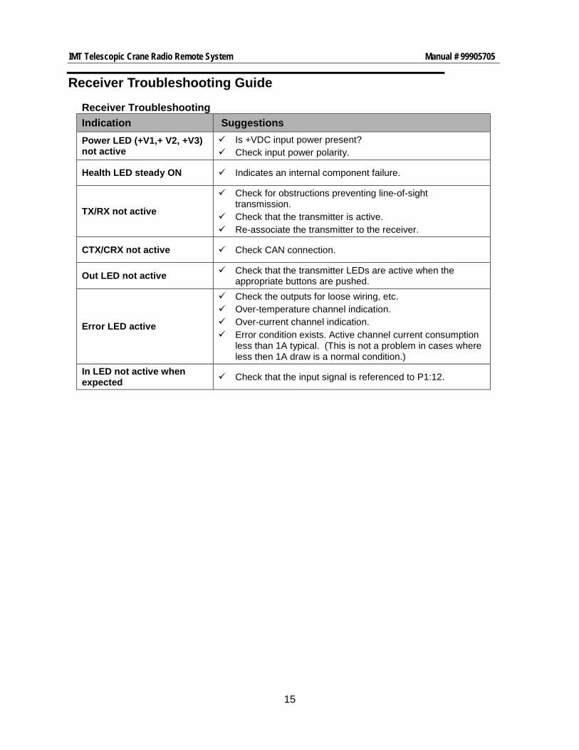
Receiver Troubleshooting Guide
Receiver Troubleshooting Indication Suggestions Power LED (+V1,+ V2, +V3) not active
Is +VDC input power present? Check input power polarity.
Health LED steady ON Indicates an internal component failure.
TX/RX not active
Check for obstructions preventing line-of-sight transmission.
Check that the transmitter is active. Re-associate the transmitter to the receiver.
CTX/CRX not active Check CAN connection.
Out LED not active Check that the transmitter LEDs are active when the appropriate buttons are pushed.
Error LED active
Check the outputs for loose wiring, etc. Over-temperature channel indication. Over-current channel indication. Error condition exists. Active channel current consumption
less than 1A typical. (This is not a problem in cases where less then 1A draw is a normal condition.)
In LED not active when expected Check that the input signal is referenced to P1:12.

16
IMT Telescopic Crane Radio Remote System Manual # 99905705
Receiver Display Messages
Receiver Display Messages A2B A2B Fault A2B switch is active
STOP STOP ACTIVE Stop switch is active
OVLD CRANE OVERLOAD 90% of setpoint* reached
SNUB CRANE SNUBBING 80% of setpoint* reached
BMDN BOOM DWN FAULT No connection
BMUP BOOM UP FAULT No connection
BMRT BOOM RET FAULT No connection
BMEX BOOM EXT FAULT No connection
WNDN WINCH DWN FAULT No connection
WNUP WINCH UP FAULT No connection
RCW ROT CW FAULT No connection
RCCW ROT CCW FAULT No connection
ESRT ENG START FAULT No connection
ESPD ENG SPEED FAULT No connection
ESTP ENG STOP FAULT No connection
COMP COMPRESSOR FAULT No connection
TRAN TRANSDUCER FAULT No connection
NORF NO RADIO COMMS Loss of Link
LBAT + VDC LOWA2B Input voltage <8V * Setpoint is 3500psi for BOOM DOWN motion only. Setpoint is 3100psi for any other motion.

17
IMT Telescopic Crane Radio Remote System Manual # 99905705
Transmitter Switch and LED Description ............................................................ 18
Transmitter Operation ......................................................................................... 19
Transmitter and Receiver Associate Mode ......................................................... 20
Transmitter Adjustments (Adjust Mode) .............................................................. 21
Receiver Channel Configuration ......................................................................... 22
Cable Wiring Information ..................................................................................... 24
SECTION 3: Fully Proportional Control System w/o Horn or ON/OFF Switches

18
IMT Telescopic Crane Radio Remote System Manual # 99905705
Transmitter Switch and LED Description 70734559 Transmitter Switch & LED Description
Switch/LED Function Red E-Stop Button IN OUT
E-STOP, the transmitter powers off immeditely. If depressed during normal crane operation, Engine Stop command is sent to chassis or auxiliary power engine; all hydrualic functions stop. Normal operating position; transmitter may be powered up.
Trigger PROPORTIONAL CONTROL - Must be release before toggling
switches 2 thru 5. Toggle switch, then pull proportional trigger slowly.
Switch 1 UP ENGINE START DOWN ENGINE START
Switch 2 UP BOOM DOWN DOWN BOOM UP
Switch 3 UP WINCH DOWN DOWN WINCH UP
Switch 4 UP EXTEND IN DOWN EXTEND OUT
Switch 5 UP ROTATE CCW DOWN ROTATE CW
Switch 6 UP TX ON/OFF DOWN SHIFT
Switch 7 UP AIR ON DOWN AIR OFF
SHIFT + UP ENGINE SPEED HIGH SHIFT + DOWN ENGINE SPEED LOW
Transmitter Diagnostic LEDs
LED Information Condition Color TX rapid blinking Transmitter is transmitting Green TX solid Switch active on transmitter RX blinking (indicationof RF signal integrity) Receiver messages received Amber RX solid Output on receiver is active ER slow blink Machine Stop depressed at power-up Amber ER solid Switch fault at power-up BATT slow blink Low battery Red

19
IMT Telescopic Crane Radio Remote System Manual # 99905705
Transmitter Operation
Turn ON the Unit This remote is powered ON by releasing the large Red mushroom-style STOP button and activating the TX ON/OFF toggle switch.
Turn OFF the Unit During normal operation, you do not need to do anything to power down the radio remote transmitter. The transmitter will automatically power down after 15 minutes of inactivity.
IMPORTANT NOTE: The primary function of the red E-Stop button is an emergency stop. If the red E-Stop button is pushed when the vehicle engine or auxiliary power unit is running, and the crane is powered up, the transmitter will send an “Engine Stop” command to the engine or power unit and shut down immediately thereby stopping all hydraulic powered functions.
Pushing the E-Stop when the vehicle engine or power unit is not running, or the crane does not have electrical power, will shut the radio transmitter off immediately without affecting the vehicle engine or power unit.
Proportional Control The proportional trigger and crane movement momentary toggle switches are used for proportional control of crane functions Winch, Telescope, Elevation and Rotation. The trigger is programmable via the configuration set-up features. See Transmitter Adjustments (Adjust Mode).
Toggle Switches SW1 through SW7 Toggle switches SW1 through SW7 are three position momentary with latched commands (where necessary) in software. These switches are used for digital control and for various setup and adjustment functions. See Transmitter Adjustments (Adjust Mode).

20
IMT Telescopic Crane Radio Remote System Manual # 99905705
Fully Proportional Radio Remote (Emulator) Handshake (Association) – Note: You must have a direct line-of-sight between the transmitter and receiver.
1. Power off transmitter and receiver (pto and/or ignition switch off)
2. Release the STOP button on the handheld by twisting it clockwise.
3. Push and hold the switches for AIR ON (up) and TX ON/OFF (up) - All LED’s will turn on (TX, RX, ER, BAT).
4. When the RX LED goes out, turn on the power to the receiver (pto and/or ignition switch).
5. Release the switches on the transmitter.
6. Both TX and RX LED’s on the transmitter should be blinking rapidly. If not, repeat steps 1 – 6.
Setting parameters:
1. HYDRAULICS OFF (Turn on ignition and pto switches, but do not start engine)
2. Turn transmitter on (receiver should be on).
3. Push and hold the switches for AIR OFF/RPM LO (down) and TX ON (up).
4. On the receiver display you will see “L-xx” (xx=number). Release switches. The transmitter is ready to set the LOW SIDE parameters.
5. Push and hold the function switch you wish to change. Use the AIR ON/RPM HI (up) switch to raise and SHIFT (down) to lower the setting. Observe the display on the receiver for the number change.
6. Once you have the new set value, push AIR OFF/RPM LOW (down) to store it. Release the switch.
7. Repeat steps 5 & 6 for each function.
8. Push and hold the switches for AIR ON/RPM HI (up) and ENGINE START (up).
9. On the receiver, you will see “H-xx” (xx=number). Release switches. The transmitter is now ready to set the high side parameters.
10. Push and hold the function switch you wish to change. Use the AIR ON/RPM HI (up) switch to raise and SHIFT (down) to lower the setting. Make sure to watch the receiver for the number change.
11. Once you have the new set value, push AIR OFF/RPM LO (down) to store it. Release the switch.
12. Repeat steps 10 & 11 for each function.
To exit calibration mode, push E-STOP or RPM or just wait for the programming mode to time out.

21
IMT Telescopic Crane Radio Remote System Manual # 99905705
These are the IMT recommended starting parameters. You may tune your transmitter to your personal preferences. IMT does recommend setting the Low above 32 for best slow resolution. IMT does not recommend setting the HIGH setting below 50.

22
IMT Telescopic Crane Radio Remote System Manual # 99905705
Receiver Channel Configuration
Receiver Channel Configuration Channel # Channel Type Output
Style Channel Logic
BOOM EXTEND M1 PWM Momentary
BOOM EXTEND (AND NOT BOOM RETRACT) If cranes load input is within 20% of overload condition reduces output by 50%.
BOOM RETRACT M2 PWM Momentary
BOOM RETRACT (AND NOT BOOM EXTEND) If cranes load input is within 20% of overload condition reduces output by 50%.
Boom Rotate CCW M3
PWM Momentary ROTATE CCW (AND NOT ROTATE CW) If cranes load input is within 20% of overload condition reduces output by 50%.
Boom Rotate CW M4 PWM Momentary
ROTATE CCW (AND NOT ROTATE CW) If cranes load input is within 20% of overload condition reduces output by 50%.
BOOM UP M5 PWM Momentary
BOOM UP (AND NOT BOOM DOWN) If cranes load input is within 20% of overload condition reduces output by 50%.
BOOM DOWN M6 PWM Momentary
BOOM DOWN (AND NOT BOOM UP) If cranes load input is within 20% of overload condition reduces output by 50%.
WINCH IN M7 PWM Momentary
WINCH IN (AND NOT WINCH OUT) If cranes load input is within 20% of overload condition reduces output by 50%.
WINCH OUT M8 PWM Momentary
WINCH OUT (AND NOT WINCH IN) If cranes load input is within 20% of overload condition reduces output by 50%.
ENGINE SPEED M9 Level
Latched ON ENGINE SPEED HIGH OR AIR ON Latched OFF ENGINE SPEED LOW OR AIR OFF
ENGINE START M10 Level Momentary ENGINE START (AND NOT ENGINE STOP)
ENGINE STOP M11 Level Momentary ENGINE STOP (AND NOT ENGINE START)
AIR COMPRESSOR
M12 Level
Latched ON AIR ON
Latched OFF AIR OFF
STOP/LINK/HOUR METER
M13 Level
Latched ON RF LINK
Latched OFF
LOSS OF RF LINK
A2B INPUT M14 Digital Input Momentary FROM NORMALLY CLOSED SWITCH: ACTIVE
LOW

23
IMT Telescopic Crane Radio Remote System Manual # 99905705
Receiver Channel Configuration Channel # Channel Type Output
Style Channel Logic
UNUSED M15
UNUSED
M16
UNUSED
AI1
LOAD INPUT
AI2
Pressure Transducer Input
4-20mA [4mA,20mA] [0,5000psi]

24
IMT Telescopic Crane Radio Remote System Manual # 99905705
Cable Wiring Information
Receiver P1 and P2 Pinout
Receiver Wiring Table Pin Signal Name Pin Signal Name P1:1 +VDC P2:1 M5: BOOM UP
P1:2 AI1: NOT USED P2:2 M6: BOOM DOWN
P1:3 M9: ENGINE SPEED P2:3 M7: WINCH IN
P1:4 M10: ENGINE START P2:4 M8: WINCH OUT
P1:5 M11: ENGINE STOP P2:5 CANH: See Error! Reference source not found.
P1:6 M12: AIR COMPRESSOR ON P2:6 UMBILICAL PWR (+5V): See Error! Reference source not found.
P1:7 M13: STOP/HOUR METER P2:7 +VDC
P1:8 M14: A2B INPUT LOW P2:8 CANL: See Error! Reference source not found.
P1:9 M15: NOT USED P2:9 M1: EXTEND
P1:10 M16: NOT USED P2:10 M2: RETRACT
P1:11 AI2: 4-20mA LOAD INPUT P2:11 M3: CCW
P1:12 -VDC, UMBILICAL COM: See 2.4 P2:12 M4: CW

25
IMT Telescopic Crane Radio Remote System Manual # 99905705
Transmitter Switch and LED Description ............................................................ 26
Transmitter Operation ......................................................................................... 27
Transmitter and Receiver Associate Mode ......................................................... 28
Transmitter Adjustments (Adjust Mode) .............................................................. 29
Receiver Channel Configuration ......................................................................... 30
Cable Wiring Information ..................................................................................... 32
SECTION 4: Fully Proportional Control System with Horn and ON/OFF Switches

26
IMT Telescopic Crane Radio Remote System Manual # 99905705
Transmitter Switch and LED Description 70734816 Transmitter Switch and LED Description Switch/LED Function Red E-Stop Button IN OUT
E-STOP, the transmitter powers off immeditely. If depressed during normal crane operation, Engine Stop command is sent to chassis or auxiliary power engine; all hydrualic functions stop. Normal operating position; transmitter may be powered up.
Trigger PROPORTIONAL CONTROL - Must be release before
toggling switches 2 thru 5. Toggle switch, then pull proportional trigger slowly.
Switch 1 UP HORN DOWN ENGINE STOP
SHIFT + UP ENGINE START Switch 2 UP BOOM DOWN
DOWN BOOM UP Switch 3 UP WINCH DOWN
DOWN WINCH UP Switch 4 UP EXTEND IN
DOWN EXTEND OUT Switch 5 UP ROTATE CCW
DOWN ROTATE CW Switch 6 UP TX ON/OFF
DOWN SHIFT Switch 7 UP AIR ON & OFF
DOWN ENGINE SPEED HIGH ON & OFF
Transmitter Diagnostic LEDs
Transmitter Operational LED Diagnostic Information LED Information Condition Color TX rapid blinking Transmitter is transmitting
Green TX solid Switch active on transmitter RX blinking (indicationof RF signal integrity) Receiver messages received
Amber RX solid Output on receiver is active ER slow blink Machine Stop depressed at power-up Amber ER solid Switch fault at power-up BATT slow blink Low battery Red

27
IMT Telescopic Crane Radio Remote System Manual # 99905705
Transmitter Operation
Turn ON the Unit This remote is powered ON by releasing the large Red mushroom-style STOP button and activating the TX ON/OFF toggle switch.
Turn OFF the Unit During normal operation, you do not need to do anything to power down the radio remote transmitter. The transmitter will automatically power down after 15 minutes of inactivity. You may also toggle the TX ON/OFF switch at any time to shut off the transmitter.
IMPORTANT NOTE: The primary function of the red E-Stop button is an emergency stop. If the red E-Stop button is pushed when the vehicle engine or auxiliary power unit is running, and the crane is powered up, the transmitter will send an “Engine Stop” command to the engine or power unit and shut down immediately thereby stopping all hydraulic powered functions.
Pushing the E-Stop when the vehicle engine or power unit is not running, or the crane does not have electrical power, will shut the radio transmitter off immediately without affecting the vehicle engine or power unit.
Proportional Control The proportional trigger and crane movement momentary toggle switches are used for proportional control of crane functions Winch, Telescope, Elevation and Rotation. The trigger is programmable via the configuration set-up features. See Transmitter Adjustments (Adjust Mode).
Toggle Switches SW1 through SW7 Toggle switches SW1 through SW7 are three position momentary with latched commands (where necessary) in software. These switches are used for digital control and for various setup and adjustment functions. See Transmitter Adjustments (Adjust Mode).

28
IMT Telescopic Crane Radio Remote System Manual # 99905705
Fully Proportional Radio Remote (Emulator) Handshake (Association) – Note: You must have a direct line-of-sight with between the transmitter and receiver.
1. Power off transmitter and receiver (pto and/or ignition switch off)
2. Release the STOP button on the handheld by twisting it clockwise.
3. Push and hold the switches for AIR ON/OFF (up) and TX ON/OFF (up) - All LED’s will turn on (TX, RX, ER, BAT).
4. When the RX LED goes out, turn on the power to the receiver (pto and/or ignition switch).
5. Release the switches on the transmitter.
6. Both TX and RX LED’s on the transmitter should be blinking rapidly. If not, repeat steps 1 – 6.
Setting parameters: 1. HYDRAULICS OFF (Turn on ignition and pto
switches, but do not start engine)
2. Turn transmitter on (receiver should be on).
3. Push and hold the switches for RPM ON/OFF (down) and TX ON/OFF (up).
4. On the receiver display you will see “L-xx” (xx=number). Release switches. The transmitter is ready to set the LOW SIDE parameters.
5. Push and hold the function switch you wish to change. Use the AIR ON/OFF (up) switch to raise and SHIFT (down) to lower the setting. Observe the display on the receiver for the number change.
6. Once you have the new set value, push RPM ON/OFF (down) to store it. Release the switch.
7. Repeat steps 5 & 6 for each function.
8. Push and hold the switches for AIR ON/OFF (up) and ENGINE START (up).
9. On the receiver, you will see “H-xx” (xx=number). Release switches. The transmitter is now ready to set the HIGH SIDE parameters.
10. Push and hold the function switch you wish to change. Use the AIR ON/OFF (up) switch to raise and SHIFT (down) to lower the setting. Make sure to watch the receiver for the number change.
11. Once you have the new set value, push RPM ON/OFF (down) to store it. Release the switch.
12. Repeat steps 10 & 11 for each function.
To exit calibration mode, push E-STOP or just wait for the programming mode to time out.

29
IMT Telescopic Crane Radio Remote System Manual # 99905705
These are the IMT recommended starting parameters. You may tune your transmitter to your personal preferences.
IMT does recommend setting the Low above 32 for best slow resolution. IMT does not recommend setting the HIGH setting below 50.

30
IMT Telescopic Crane Radio Remote System Manual # 99905705
Receiver Channel Configuration
Receiver Channel Configuration Channel # Channel Type Output
Style Channel Logic
BOOM EXTEND M1 PWM Momentary
BOOM EXTEND (AND NOT BOOM RETRACT) If cranes load input is within 20% of overload condition reduces output by 50%.
BOOM RETRACT M2 PWM Momentary
BOOM RETRACT (AND NOT BOOM EXTEND) If cranes load input is within 20% of overload condition reduces output by 50%.
Boom Rotate CCW M3
PWM Momentary ROTATE CCW (AND NOT ROTATE CW) If cranes load input is within 20% of overload condition reduces output by 50%.
Boom Rotate CW M4 PWM Momentary
ROTATE CCW (AND NOT ROTATE CW) If cranes load input is within 20% of overload condition reduces output by 50%.
BOOM UP M5 PWM Momentary
BOOM UP (AND NOT BOOM DOWN) If cranes load input is within 20% of overload condition reduces output by 50%.
BOOM DOWN M6 PWM Momentary
BOOM DOWN (AND NOT BOOM UP) If cranes load input is within 20% of overload condition reduces output by 50%.
WINCH IN M7 PWM Momentary
WINCH IN (AND NOT WINCH OUT) If cranes load input is within 20% of overload condition reduces output by 50%.
WINCH OUT M8 PWM Momentary
WINCH OUT (AND NOT WINCH IN) If cranes load input is within 20% of overload condition reduces output by 50%.
ENGINE SPEED M9 Level
Latched ON ENGINE SPEED HIGH OR AIR ON Latched OFF ENGINE SPEED LOW OR AIR OFF
ENGINE START M10 Level Momentary ENGINE START (AND NOT ENGINE STOP)
ENGINE STOP M11 Level Momentary ENGINE STOP (AND NOT ENGINE START)
AIR COMPRESSOR
M12 Level
Latched ON AIR ON
Latched OFF AIR OFF
STOP/LINK/HOUR METER
M13 Level
Latched ON RF LINK
Latched OFF
LOSS OF RF LINK
A2B INPUT M14 Digital Input Momentary FROM NORMALLY CLOSED SWITCH: ACTIVE
LOW

31
IMT Telescopic Crane Radio Remote System Manual # 99905705
Receiver Channel Configuration Channel # Channel Type Output
Style Channel Logic
WARNING 1 OUT/HORN
M15 Level Momentary AI2 > (Pressure Input > 80%)*
WARNING 2 OUT/HORN
M16 Level Momentary Ai2 > (Pressure Input > 100%)*
UNUSED
AI1
LOAD INPUT
AI2
Pressure Transducer Input
4-20mA [4mA,20mA] [0,5000psi]
*Current dependent on motion function Boom Down/Non-Boom Down/Snubby/Overload characteristics.
Note: Air compressor stays on with signal loss – loss of link – and the engine runs at high idle.
Note: Machine Stop latches off all functions and will activate Engine STOP output for 10 seconds.

32
IMT Telescopic Crane Radio Remote System Manual # 99905705
Cable Wiring Information
Figure 9: Receiver P1 and P2 Pinout
Receiver Wiring Table Pin Signal Name Pin Signal Name P1:1 +VDC P2:1 M5: BOOM UP
P1:2 AI1: NOT USED P2:2 M6: BOOM DOWN
P1:3 M9: ENGINE SPEED P2:3 M7: WINCH IN
P1:4 M10: ENGINE START P2:4 M8: WINCH OUT
P1:5 M11: ENGINE STOP P2:5 CANH: See 2.7
P1:6 M12: AIR COMPRESSOR ON P2:6 UMBILICAL PWR (+5V): See 2.7
P1:7 M13: STOP/HOUR METER P2:7 +VDC
P1:8 M14: A2B INPUT LOW P2:8 CANL: See 2.7
P1:9 M15: WARNING 1/HORN P2:9 M1: EXTEND
P1:10 M16: WARNING 2/HORN P2:10 M2: RETRACT
P1:11 AI2: 4-20mA LOAD INPUT P2:11 M3: CCW
P1:12 -VDC, UMBILICAL COM: See 2.4 P2:12 M4: CW
P1 P2
36mm (1.4”)

33
IMT Telescopic Crane Radio Remote System Manual # 99905705
Iowa Mold Tooling Co., Inc.